EP2698232A2 - Dispositif de peinture - Google Patents
Dispositif de peinture Download PDFInfo
- Publication number
- EP2698232A2 EP2698232A2 EP13005361.4A EP13005361A EP2698232A2 EP 2698232 A2 EP2698232 A2 EP 2698232A2 EP 13005361 A EP13005361 A EP 13005361A EP 2698232 A2 EP2698232 A2 EP 2698232A2
- Authority
- EP
- European Patent Office
- Prior art keywords
- robot
- painting
- arm
- rotatable
- verfahrschiene
- Prior art date
- Legal status (The legal status is an assumption and is not a legal conclusion. Google has not performed a legal analysis and makes no representation as to the accuracy of the status listed.)
- Granted
Links
Images


Classifications
-
- B—PERFORMING OPERATIONS; TRANSPORTING
- B05—SPRAYING OR ATOMISING IN GENERAL; APPLYING FLUENT MATERIALS TO SURFACES, IN GENERAL
- B05B—SPRAYING APPARATUS; ATOMISING APPARATUS; NOZZLES
- B05B13/00—Machines or plants for applying liquids or other fluent materials to surfaces of objects or other work by spraying, not covered by groups B05B1/00 - B05B11/00
-
- B—PERFORMING OPERATIONS; TRANSPORTING
- B25—HAND TOOLS; PORTABLE POWER-DRIVEN TOOLS; MANIPULATORS
- B25J—MANIPULATORS; CHAMBERS PROVIDED WITH MANIPULATION DEVICES
- B25J5/00—Manipulators mounted on wheels or on carriages
- B25J5/02—Manipulators mounted on wheels or on carriages travelling along a guideway
-
- B—PERFORMING OPERATIONS; TRANSPORTING
- B05—SPRAYING OR ATOMISING IN GENERAL; APPLYING FLUENT MATERIALS TO SURFACES, IN GENERAL
- B05B—SPRAYING APPARATUS; ATOMISING APPARATUS; NOZZLES
- B05B13/00—Machines or plants for applying liquids or other fluent materials to surfaces of objects or other work by spraying, not covered by groups B05B1/00 - B05B11/00
- B05B13/02—Means for supporting work; Arrangement or mounting of spray heads; Adaptation or arrangement of means for feeding work
- B05B13/04—Means for supporting work; Arrangement or mounting of spray heads; Adaptation or arrangement of means for feeding work the spray heads being moved during spraying operation
- B05B13/0431—Means for supporting work; Arrangement or mounting of spray heads; Adaptation or arrangement of means for feeding work the spray heads being moved during spraying operation with spray heads moved by robots or articulated arms, e.g. for applying liquid or other fluent material to three-dimensional [3D] surfaces
-
- B—PERFORMING OPERATIONS; TRANSPORTING
- B05—SPRAYING OR ATOMISING IN GENERAL; APPLYING FLUENT MATERIALS TO SURFACES, IN GENERAL
- B05B—SPRAYING APPARATUS; ATOMISING APPARATUS; NOZZLES
- B05B13/00—Machines or plants for applying liquids or other fluent materials to surfaces of objects or other work by spraying, not covered by groups B05B1/00 - B05B11/00
- B05B13/02—Means for supporting work; Arrangement or mounting of spray heads; Adaptation or arrangement of means for feeding work
- B05B13/04—Means for supporting work; Arrangement or mounting of spray heads; Adaptation or arrangement of means for feeding work the spray heads being moved during spraying operation
- B05B13/0447—Installation or apparatus for applying liquid or other fluent material to conveyed separate articles
- B05B13/0452—Installation or apparatus for applying liquid or other fluent material to conveyed separate articles the objects being vehicle components, e.g. vehicle bodies
-
- B—PERFORMING OPERATIONS; TRANSPORTING
- B05—SPRAYING OR ATOMISING IN GENERAL; APPLYING FLUENT MATERIALS TO SURFACES, IN GENERAL
- B05B—SPRAYING APPARATUS; ATOMISING APPARATUS; NOZZLES
- B05B16/00—Spray booths
-
- B—PERFORMING OPERATIONS; TRANSPORTING
- B05—SPRAYING OR ATOMISING IN GENERAL; APPLYING FLUENT MATERIALS TO SURFACES, IN GENERAL
- B05B—SPRAYING APPARATUS; ATOMISING APPARATUS; NOZZLES
- B05B16/00—Spray booths
- B05B16/40—Construction elements specially adapted therefor, e.g. floors, walls or ceilings
-
- B—PERFORMING OPERATIONS; TRANSPORTING
- B05—SPRAYING OR ATOMISING IN GENERAL; APPLYING FLUENT MATERIALS TO SURFACES, IN GENERAL
- B05B—SPRAYING APPARATUS; ATOMISING APPARATUS; NOZZLES
- B05B5/00—Electrostatic spraying apparatus; Spraying apparatus with means for charging the spray electrically; Apparatus for spraying liquids or other fluent materials by other electric means
- B05B5/08—Plant for applying liquids or other fluent materials to objects
-
- B—PERFORMING OPERATIONS; TRANSPORTING
- B25—HAND TOOLS; PORTABLE POWER-DRIVEN TOOLS; MANIPULATORS
- B25J—MANIPULATORS; CHAMBERS PROVIDED WITH MANIPULATION DEVICES
- B25J19/00—Accessories fitted to manipulators, e.g. for monitoring, for viewing; Safety devices combined with or specially adapted for use in connection with manipulators
- B25J19/0025—Means for supplying energy to the end effector
- B25J19/0029—Means for supplying energy to the end effector arranged within the different robot elements
-
- B—PERFORMING OPERATIONS; TRANSPORTING
- B25—HAND TOOLS; PORTABLE POWER-DRIVEN TOOLS; MANIPULATORS
- B25J—MANIPULATORS; CHAMBERS PROVIDED WITH MANIPULATION DEVICES
- B25J9/00—Program-controlled manipulators
-
- B—PERFORMING OPERATIONS; TRANSPORTING
- B25—HAND TOOLS; PORTABLE POWER-DRIVEN TOOLS; MANIPULATORS
- B25J—MANIPULATORS; CHAMBERS PROVIDED WITH MANIPULATION DEVICES
- B25J9/00—Program-controlled manipulators
- B25J9/0009—Constructional details, e.g. manipulator supports, bases
-
- B—PERFORMING OPERATIONS; TRANSPORTING
- B25—HAND TOOLS; PORTABLE POWER-DRIVEN TOOLS; MANIPULATORS
- B25J—MANIPULATORS; CHAMBERS PROVIDED WITH MANIPULATION DEVICES
- B25J9/00—Program-controlled manipulators
- B25J9/0084—Program-controlled manipulators comprising a plurality of manipulators
-
- B—PERFORMING OPERATIONS; TRANSPORTING
- B25—HAND TOOLS; PORTABLE POWER-DRIVEN TOOLS; MANIPULATORS
- B25J—MANIPULATORS; CHAMBERS PROVIDED WITH MANIPULATION DEVICES
- B25J9/00—Program-controlled manipulators
- B25J9/0093—Program-controlled manipulators co-operating with conveyor means
-
- B—PERFORMING OPERATIONS; TRANSPORTING
- B25—HAND TOOLS; PORTABLE POWER-DRIVEN TOOLS; MANIPULATORS
- B25J—MANIPULATORS; CHAMBERS PROVIDED WITH MANIPULATION DEVICES
- B25J9/00—Program-controlled manipulators
- B25J9/02—Program-controlled manipulators characterised by movement of the arms, e.g. cartesian coordinate type
- B25J9/04—Program-controlled manipulators characterised by movement of the arms, e.g. cartesian coordinate type by rotating at least one arm, excluding the head movement itself, e.g. cylindrical coordinate type or polar coordinate type
- B25J9/046—Revolute coordinate type
Definitions
- the invention relates to a painting device for painting components, in particular for painting motor vehicle bodies or parts thereof. Furthermore, the invention relates to an associated method for producing, testing and / or mounting a painting device.
- multiaxial painting robots which have as an application device, for example, a rotary atomizer.
- the control of the painting robot takes place here by a robot controller, which is usually arranged outside the painting booth in a control cabinet and is connected to the painting robot during assembly of the paint shop.
- the various supply lines for the media required for operation of the painting robot for example compressed air, paints, dishwashing liquid
- These conventional painting plants have various disadvantages, as will be explained below.
- connection of the painting robot during final assembly requires a considerable amount of personnel, which increases assembly costs.
- a certain assembly time is required, resulting in a conversion of an existing paint shop a corresponding conversion and downtime of the paint shop due, which can lead to production losses.
- the invention is therefore based on the object to provide a correspondingly improved painting and an associated method.
- the invention aims to avoid assembly errors in the final assembly of the painting robot in the paint shop, if possible.
- the invention comprises the general technical teaching to deliver the painting robot pre-assembled as a finished module with the robot control and a mechanical support, so that the preassembled module then at the customer in the paint shop can be easily assembled without great installation time.
- the painting device according to the invention preferably has a multi-axis painting robot, wherein such painting robots are described per se from the prior art and therefore need not be described in detail. It is therefore only briefly to mention that the painting robot according to the invention including a multi-axis robot hand axis preferably has 5, 6, 7 or 8 movable axes.
- the term used in the invention of a painting robot is thus in the preferred embodiment to distinguish from conventional roofing machines or side machines, which are also used for painting motor vehicle bodies.
- the painting robot preferably performs a rotary atomizer as the application device, but other types of atomizers are also possible within the scope of the invention, such as airmix devices, airless devices, air atomizers or ultrasonic atomisers.
- the invention is suitable for the application of paints, such as wet paints or powder coatings.
- paints such as wet paints or powder coatings.
- different types of paint can be applied, such as primer, base coat or clear coat.
- the invention is not limited to the coating agent types mentioned above by way of example, but in principle can also be realized with other types of coating compositions.
- the painting device according to the invention in a conventional manner, a robot control, which with the Paint robot is connected and controls this according to a predetermined program.
- the robot control is in this case housed in a control cabinet, which is known per se from the prior art.
- control cabinet forms a support column for the painting robot or that the support column for the painting robot forms the control cabinet and houses the robot controller.
- the control cabinet therefore has a double function within the scope of the invention in that the control cabinet contains the robot control on the one hand and serves as a mechanical support element for the painting robot on the other hand.
- This dual function of the control cabinet advantageously allows pre-assembly of the painting robot with the robot controller and the control cabinet, so that the pre-assembled module can then be easily and quickly assembled by the customer in the paint shop.
- the control cabinet is therefore modified in comparison with the conventional control cabinets in order to be able to fulfill the mechanical support function for the painting robot.
- the painting robot is mechanically supported exclusively by one or more control cabinets, each designed as a support column.
- control cabinets each designed as a support column.
- the control cabinet formed as a support column it is alternatively also possible for the control cabinet formed as a support column to be merely a mechanically supporting element in addition to further support elements, so that the control cabinet only contributes to the mechanical support of the painting robot.
- control cabinet in terms of the shape of the control cabinet is not limited to a particular Form is limited, as it usually has a cabinet. Rather, the control cabinet may also have other shapes, such as the shape of a console or a box.
- the invention enables a pre-assembly of the painting robot with the robot controller and the control cabinet designed as a support column.
- the control cabinet preferably has an interface through which all fluidic and electrical supply lines can be connected, which are required for operation of the painting robot. This is advantageous because then only a single interface must be connected to allow the operation of the painting robot, whereby the final assembly time is reduced.
- the supply lines required for operation of the painting robot in this case are preferably guided in the preassembled module from the interface of the control cabinet to the painting robot, so that no further assembly work is required within the pre-assembled module during final assembly.
- the invention is not limited to the variant described above in which the painting robot is delivered together with the robot controller and the control cabinet designed as a support column as a preassembled module. Rather, it is within the scope of the invention also possible that the painting robot delivered separately from the robot controller and the control cabinet and then finally assembled at the customer and connected to the robot controller.
- the painting robot preferably has an interface, via which the painting robot is detachably connected to the control cabinet designed as a support column. This interface between the painting robot and the control cabinet preferably also serves for the mechanical connection between the painting robot and the control cabinet designed as a support column.
- the interface between the painting robot and the control cabinet formed as a support column thus preferably contains all fluidic supply lines (eg lines for paint, detergent and compressed air) and electrical supply lines (eg control lines and sensor lines) between the control cabinet and the painting robot, which are required for operation of the painting robot ,
- fluidic supply lines eg lines for paint, detergent and compressed air
- electrical supply lines eg control lines and sensor lines
- the respective interface preferably comprises the pneumatic line which is required for the compressed air supply of the painting robot, for example in order to drive a compressed air turbine of a rotary atomizer.
- the interface preferably comprises at least one color line for feeding the paint to be applied.
- the invention preferably also includes a rinsing agent line, via which a rinsing agent can be supplied in order to rinse the painting robot and in particular the rotary atomizer during a color change.
- the interface preferably also includes a return line for returning detergent and / or paint from the painting robot.
- the interface preferably also contains electrical control lines for controlling the robot by the robot controller and / or at least one sensor line for the feedback of sensor variables from the painting robot to the robot controller.
- the painting robot is preferably a multiaxial painting robot which has, for example, including a multi-axis robot hand axis 5, 6, 7 or 8 movable axes.
- the painting robot comprises a fixedly mounted or displaceable robot base, a rotatable robot part, a pivotable proximal robot arm ("arm 1") and a pivotable distal robot arm (“arm 2").
- the rotatable robot part is rotatable about a substantially vertical axis of rotation relative to the robot base, wherein the rotatable robot part is preferably located under the robot base.
- the invention is not limited to an axis of rotation oriented exactly with respect to the axis of rotation of the rotatable robot part. Rather, the axis of rotation can also be slightly angled. Decisive is only in this embodiment, that the axis of rotation of the rotary robot part is substantially upright.
- the proximal robotic arm is preferably pivotable about a pivot axis that is substantially horizontal, as well as the distal robotic arm, which is also pivotable about a preferably horizontal pivot axis relative to the proximal robotic arm.
- the rotary robot part is rotatable about a substantially horizontal axis of rotation relative to the robot base.
- the pivot axes of the proximal robot arm and of the distal robot arm preferably extend at right angles to the axis of rotation of the rotatable robot part, in particular at right angles to the conveying direction of the components in the paint shop. This embodiment is suitable for example for painting bumpers.
- the rotary robot part can optionally under the robot base, on the robot base or laterally adjacent to the robot base.
- the rotatable robot part is arranged under the robot base, since the painting robot is then particularly well suited for interior painting of motor vehicle bodies.
- the invention comprises a special guidance of the supply hoses required for the operation of the painting robot within the painting robot.
- the media required for operation of the painting robot eg compressed air, paint and detergent
- these supply hoses are guided in the individual joints between the adjacent robot members in each case by the so-called neutral fiber.
- the neutral fiber is an imaginary line through the joint, which is not subjected to tensile or longitudinal compression during joint rotation, but is subjected to bending stress only.
- the laying of the supply hoses in the neutral fiber of the joints offers the advantage that the supply hoses are not mechanically stressed in the axial direction.
- the supply hoses in each case run through the axis of rotation of the joints, which also reduces the mechanical load on the supply hoses.
- the individual supply hoses in the painting robot preferably extend in each case from the rotatable robot part to the distal robot arm in each case Hose level, so that the supply hoses are bent in a pivoting of the robot arms only in the hose level.
- the hose plane is thus preferably at right angles to the axis of rotation of the robot arms.
- the painting robot according to the invention preferably comprises application technology, such as, for example, a color changer for selecting a desired color, wherein the color changer is connected on the input side to a plurality of ink feed lines and on the output side to an atomizer.
- the application technique mounted in or on the painting robot may include a metering pump or other metering systems, such as a metering cylinder, a wobble piston pump, radial screws.
- the application technique mounted in or on the painting robot may include a motor for driving the metering pump or the other application technology.
- the application technique mounted on or in the painting robot can include a color pressure regulator for regulating the application pressure and / or a high voltage generator for generating the high voltage required for an electrostatic painting.
- the above-mentioned application technique can be arranged in or on the proximal robot arm.
- the application technique it is possible within the scope of the invention for the application technique to be arranged in or on the distal robot arm.
- the application technique is distributed over the various robot arms.
- the application technique for the rarely used lacquers (“low runner”) is preferably located on or in the proximal robot arm ("arm 1"), While the application technique for the commonly used coatings on or in the distal arm (“arm 2”) is located so that the lowest possible color change losses occur in the commonly used paints ("High Runner").
- the distal robot arm is pivotally connected to the proximal robot arm via a so-called elbow joint, the elbow joint being directed downwards in at least one robot position ("elbow-down").
- the robot base is preferably arranged above the motor vehicle bodies to be painted, so that the atomizer is located below the robot base.
- This increased arrangement of the painting robot is advantageous, inter alia, because excess coating agent residues ("overspray") are pressed downwards by the downwardly directed air flow in the painting booth and therefore deposit to a lesser extent on the elevated painting robot.
- the increased arrangement of the painting robot thus advantageously reduces the tendency of the painting robot to become soiled.
- This "ellbow-down" facilitates interior painting of motor vehicle bodies when the distal robot arm is substantially horizontal in a robot position and is insertable horizontally into the interior of a vehicle body to paint the interior.
- the structure on the distal robot arm (“Arm 2") may be higher than in the robot position "Ellbow Up". This means that more application technology is built into the distal robotic arm can reduce the color and solvent consumption.
- the painting robot according to the invention preferably also allows a robot position in which the elbow joint between the proximal robot arm and the distal robot arm is directed upwards ("elbow up").
- the painting device preferably comprises a conveyor which promotes the components to be painted by the painting, which is known per se from the prior art and therefore need not be described in detail.
- the robot base is preferably offset upwards relative to the conveyor, in particular at a height above the upper side of the components to be painted. This increased arrangement of the painting robot reduces - as already mentioned above - the susceptibility to fouling of the painting robot, since the linear flow through the painting booth from top to bottom pushes the paint particles not adhering to the components ("overspray") downwards.
- the robot base is mounted stationary, so that the robot base is not movable.
- the robot base can be attached directly to the control column forming the support column.
- the robot base with the painting robot is movable on a travel rail, which is known per se from the prior art and therefore need not be described in detail.
- the preassembled module preferably also includes the positioning rail.
- the painting device additionally has a handling robot which can open and close doors or hoods of motor vehicle bodies to be painted, so that the actual painting robot can carry out interior painting of the motor vehicle bodies.
- the handling robot can in this case be mounted on a positioning rail, wherein the positioning rail is preferably likewise mounted on the control cabinet designed as a support column.
- the preassembled module can therefore also comprise the displacement rail for the handling robot and / or the handling robot.
- the travel rail of the handling robot can be mechanically supported within the scope of the invention by the control cabinet designed as a support column. However, there is also the possibility that the travel rail for the handling robot is additionally supported by further mechanical support structures.
- the positioning rail for the handling robot can be mounted on the same support column on which the painting robot is also mounted in a stationary manner.
- the painting robot is preferably mounted above the handling robot on the support column, which facilitates the operation.
- the positioning rail for the handling robot can be designed as a so-called stub rail. This means that the displacement rail for the handling robot is shorter than the spray booth. Furthermore, it may be advantageous if the positioning rail for the handling robot is offset relative to the painting robot in the conveying direction of the components. This is particularly advantageous when the components to be coated are transported through the paint booth at a high conveying speed, since the displacement of the handling rail for the handling robot then allows more time for the handling robot in the conveying direction.
- the painting robot is preferably arranged in a painting booth, wherein the painting booth preferably has smooth-surface cabin walls ("clean wall").
- the cabin walls of the paint booth are preferably at least partially transparent or at least have a viewing window to allow a visual inspection of the painting operation from the outside.
- control cabinet designed as a support column is preferably arranged outside the paint booth. This offers the advantage that the paint booth does not need to be entered to perform maintenance on the robot controller housed in the control cabinet.
- the painting robot in addition to a sprayer on a handling handle to open doors or hoods to be painted vehicle bodies.
- the painting robot is therefore bifunctional in this embodiment, since the painting robot can either apply paint or serve as a handling robot.
- control column forming support column is not arranged stationary, but movable.
- the support column can be moved on one or more traversing rails, wherein the traversing rail for the support column is preferably aligned parallel to the conveying direction of the motor vehicle bodies to be painted.
- the support column is vertically aligned, wherein the painting robot along the support column is movable in the vertical direction.
- the painting robot can be moved along a travel rail, wherein the movement rail is preferably aligned in the conveying direction of the components to be painted, so that the movement rail runs along the painting line.
- the painting robot is in this case connected by a substantially vertically oriented carrier with the positioning rail, wherein the carrier is guided on its upper side by the Verfahrschiene and along the Verfahrschiene is movable, while the carrier carries on its underside the robot base of the painting robot.
- the carrier thus ensures that the robot base of the painting robot is located in the lower region of the painting booth, although the painting robot can be moved on the elevated positioning rail.
- the carrier between the Verfahrschiene and the painting robot thus allows a lowering of the painting robot relative to the Verfahrschiene.
- the invention comprises a variant in which a conveyor is arranged in the paint booth, which promotes the components to be painted in a predetermined conveying direction through the painting, such conveyors are per se in the prior art and therefore need not be described in detail.
- the painting robot is here also mounted on a travel rail movable, wherein a special feature is that the positioning rail is aligned transversely to the conveying direction of the components to be painted.
- the travel rail for the painting robot thus preferably runs at right angles to the conveying direction of the components to be painted, as a result of which a painting booth with a very short cabin length can be realized.
- the range of motion for the painting robot on the positioning rail is generally limited by the lateral cabin wall of the painting booth.
- the cabin wall in the extension of the transverse Verfahrschiene has lateral bulges, so that the painting robot can be driven on the Verfahrschiene in the bulge of the spray booth.
- the cabin width of the paint booth is therefore not constant over the length of the cabin, but varies, the cabin width laterally next to the Verfahrschiene the painting robot is greater than in the conveying direction before and behind the Verfahrschiene the painting robot.
- the invention comprises a novel painting robot with a robot base, on which at least two robot arms or other robot members are articulated movably.
- the two robot arms each carry an atomizer.
- one robot arm guides an atomizer, while the other robot arm guides a handling tool, in particular a gripper for opening or closing a hood or door of a vehicle body.
- the invention also includes a method for producing, testing and / or assembling a painting device according to the invention, wherein the method according to the invention is characterized in that the control cabinet is mechanically reinforced during manufacture, so that it can mechanically support the painting robot.
- the manufacturing method according to the invention is characterized in that the painting robot is fastened to the control cabinet designed as a support column directly or by means of a Verfahrschiene or a mounting adapter.
- a pre-assembly of a module which comprises the painting robot, the control cabinet, the robot control and / or the positioning rail, preferably takes place on the manufacturer side and not on the customer side.
- This pre-assembly of the module preferably allows testing of the preassembled module, the testing also being made by the manufacturer. As part of these tests, on the one hand, the fluidic functioning of the atomizer can be tested. So it can be tested if the atomizer is working properly. In addition, the tests on the preassembled module may also include the proper mobility of the painting robot. Further, as part of the test work on the preassembled module, it can be checked whether the electrostatic coating agent charging is functioning properly. Finally, there is still the possibility that as part of the test work on the pre-assembled module It is tested whether the painting robot can be moved properly on its travel rail.
- the method according to the invention then preferably also comprises the transport of the preassembled module to a mounting location at the customer.
- the method according to the invention then preferably also comprises the final assembly of the preassembled and / or tested module at the installation site, wherein the module is then mechanically anchored and connected to all lines which are required for operation of the painting robot and the associated atomizer.
- further test work is then usually not required, whereby the final assembly time is significantly reduced.
- the inventive method also includes the interior painting of motor vehicle bodies, wherein the painting robot is positioned so that the elbow joint between the proximal robot arm and the distal robot arm is directed downward.
- the distal robot arm with the atomizer is then positioned so that the distal robot arm is laterally adjacent to the vehicle body to be painted substantially perpendicular to the conveying direction of the components to be painted.
- the distal robot arm with the atomizer is then aligned substantially horizontally and is introduced in the horizontal direction in the interior of the vehicle body to be painted, there to paint the interior.
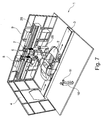
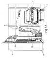
- FIG. 1 shows a painting booth 1 according to the invention, which is arranged in a paint shop for painting motor vehicle bodies 2, wherein the motor vehicle bodies 2 are transported by a conveyor 3 in the direction of arrow through the paint booth 1.
- further painting booths can be arranged to apply other coating agents to the motor vehicle bodies 2.
- a basecoat film can be applied to the motor vehicle bodies 2 in the paint booth 1.
- a primer "primer" on the motor vehicle bodies 2 applied.
- a clear coat is then applied to the motor vehicle bodies 2.
- the paint booth 1 has over the entire circumference circumferentially smooth-surfaced cabin walls 4, 5, wherein the cabin walls are partially not shown to allow the insight into the interior of the paint booth 1.
- An advantage of the smooth-surfaced cabin walls 4, 5 is the low susceptibility to fouling and good cleaning ability.
- the cabin walls 4, 5 are largely transparent, which allows a visual inspection of the running in the interior of the spray booth 1 Lackier Kohls by a person located outside of the spray booth 1.
- the two control cabinets 8, 9 are located outside of the painting booth 1 and contain a robot controller for controlling the painting robots 6, 7.
- the robot control in the control cabinets 8, 9 can therefore be maintained without the maintenance personnel having to enter the paint booth 1.
- control cabinets 8, 9 are in this case mechanically solid massively reinforced compared to conventional control cabinets to meet in addition to the harboring of the robot controller and a mechanical support function for the painting robots 6, 7 can.
- the two painting robots 6, 7 together with the associated control cabinets 8, 9 and the robot controller located therein form a preassembled module which is supplied preassembled and tested by the manufacturer of the painting robots, so that these modules can be easily installed by the customer during final assembly , In the final assembly, therefore, only a mechanical fixation of the control cabinets 8, 9 is required and a connection of the control cabinets 8, 9 to the lines required for operation (for example for compressed air, paints, dishwashing liquid, electricity, etc.).
- the robot controls located in the control cabinets 8, 9 can be programmed by an operator 10 outside the paint booth 1 by means of a portable programmer 11, the programmer 11 enabling wireless data transmission from and to the robot controls.
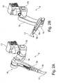
- FIGS. 2A to 2F show the structure of the painting robots 6, 7.
- the painting robots 6, 7 consist essentially of a robot base 12, a rotatable robot part 13, a proximal robot arm 14, a distal robot arm 15, a robot hand axis 16 and a rotary atomizer 17.
- the rotatable robot part 13 is in this case arranged below the robot base 12 and rotatable relative to the robot base 12 about a vertical axis of rotation.
- proximal robot arm 14 is pivotable relative to the rotatable robot part 13 about a horizontal pivot axis.
- distal robot arm 15 which is pivotable about a horizontally extending pivot axis relative to the proximal robot arm 14.
- the proximal robot arm 14 is connected to the distal robot arm 15 by means of an elbow joint 18.
- the elbow joint 18 In the in FIG. 2A shown robot position is the elbow 18 upwards ("Ellbow up”).
- the elbow joint 18 In the in FIG. 2B The robot position shown, the elbow joint 18, however, directed downwards ("Ellbow down”).
- the elbow joint 18 In the FIG. 2B shown robot position with the downwardly directed elbow joint 18 is particularly well suited for interior painting of motor vehicle bodies 2, since the distal robot arm 15 can then be introduced laterally in a simple manner in the vehicle body 2 to be painted.
- the robot base 12 has an interface 19 in order to connect the supply lines required for operation of the painting robot 6.
- the robot base 12 also includes a mechanical interface 20 for fastening the painting robot 6 to the control cabinet 8.
- FIGS. 2D to 2F continue to show that between the robot base 12 and the rotary atomizer 17 bendable supply hoses 21 extend, for example, to perform the paint to be applied.
- the supply tubes 21 between the rotatable robot part and the distal robot arm 15 each extend in a tube plane which is aligned at right angles to the pivot axis of the robot arms 14, 15. This means that the supply hoses 21 are only subjected to bending in the hose plane when the robot arms 14, 15 are pivoted, ie. only in one direction.
- the proximal robot arm 14 is pivotable about a pivot axis 22 relative to the rotatable robot part 13, wherein the supply tubes 21 in the joint between the proximal robot arm 14 and the rotatable robot part 13 are guided by the pivot axis 22.
- This offers the advantage that the supply hoses 21 are subjected to only relatively minor mechanical loads during a pivoting movement of the proximal robot arm 14.
- the supply hoses 21 are guided in the joints in each case in the so-called neutral fiber in which only bending loads of the supply hoses 21 occur, but no axial tensile or compressive forces.
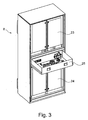
- FIG. 3 shows a perspective view of the control cabinet 8, wherein the in FIG. 1 shown control cabinet 9 is identical.
- the control cabinet 8 has space for a robot controller 23, 24 in the upper area and in the lower area.
- control cabinet 8 in the middle of a drawer 25 in which, for example, spare parts, operating instructions or even abandoned cleaning cloths can be accommodated.
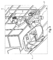
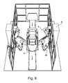
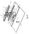
- FIGS. 4 to 6 show an alternative embodiment of a painting booth 1 according to the invention, which largely corresponds to the painting booth 1 described above, so that reference is made to avoid repetition to the above description, wherein for corresponding details in the following the same reference numerals are used.
- a special feature of this embodiment is that in addition to the painting robot 6, a handling robot 26 is provided, which has the task to open the doors of the motor vehicle bodies 2 for a subsequent interior painting by the painting robot 6.
- the handling robot 26 is mounted below the painting robot 6 on a stub rail 27 and can be moved in the direction of the arrow.
- the stub rail 27 of the handling robot 26 is in this case offset relative to the painting robot 6 in the conveying direction. This is advantageous so that the handling robot 26 still has enough time after finishing the interior painting by the painting robot 6 to close the door of the motor vehicle body 2 before the motor vehicle body 2 leaves the reach of the handling robot 26 in the direction of the arrow.
- FIGS. 7 and 8th show a further embodiment of a painting booth 1 according to the invention, which largely corresponds to the embodiments described above, so that reference is made to avoid repetition of the above description, wherein the same reference numerals are used for the corresponding details below.
- a special feature of this embodiment is that the painting robots 6, 7 are not fixedly mounted in this embodiment, but on a common rail 28th
- handling robots 26 are suspended from the travel rail 28 in this embodiment.
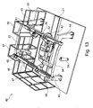
- FIG. 9 shows a further embodiment of a painting booth 1 according to the invention, which largely corresponds to the embodiment described above, so that reference is made to avoid repetition of the above description, wherein for corresponding details in the following the same reference numerals are used.
- a special feature of this embodiment is that a further travel rail 29 is mounted on the control cabinets 8, 9 designed as a support column in the lower region.
- the travel rail 29 in this case carries the handling robot 26, whereas the upper travel rail 28 carries the painting robots 6, 7.
- FIG. 10 shows a perspective view of a modified Lackierroboters 6, in addition to the rotary atomizer 17 carries a handling handle 30 with which the painting robot 6 hoods 31 of the motor vehicle bodies 2 can open or close.
- the painting robot 6 is thus bifunctional in this embodiment and can either apply paint or serve as a handling robot.
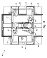
- FIG. 11 an embodiment of a painting booth 1 according to the invention, which largely corresponds to the preferred embodiment described above, so that reference is made to avoid repetition of the above description, wherein for corresponding details below, the same reference numerals are used.
- a special feature of this embodiment is that the axis of rotation between the robot base 12 and the rotatable robot part 13 is aligned horizontally and parallel to the transport direction of the conveyor 3 extends.
- pivot axes of the proximal robot arm 14 and the distal robot arm run in a plane which is aligned at right angles to the transport direction of the conveyor 3.
- FIG. 12 shows a further embodiment of a coating device according to the invention with a movable painting robot 32, the painting robot 32 a robot base 33, a proximal robot arm 34, a distal robot arm 35 and an atomizer 36 which is guided on the distal robot arm 35.
- the painting robot 32 can be moved on a support column 37 in the vertical direction (Z direction).
- the support column 37 not only serves for the mechanical guidance of the painting robot 32, but also contains a robot control and / or application technology for the painting robot 32, wherein the pneumatics for the painting robot 32 can be integrated into the support column 37.
- the support column 37 thus forms in this embodiment a control cabinet for the painting robot.
- the support column 37 is movable on two superimposed, parallel traverse rails 38, 39 in the X direction, i. in the conveying direction of the vehicle bodies to be painted.
- FIGS. 13 and 15 show a further embodiment of a paint booth 40 according to the invention, which can be arranged in a paint shop, with 40 more paint stations are in the conveying direction in front of and behind the paint booth.
- a conveyor 41 runs along the motor vehicle bodies 42 are linearly transported through the paint booth 40, which is known per se from the prior art and therefore need not be described in detail.
- the two output side arranged support columns 44, 45 carry on their upper side together a further Verfahrschiene 50, which is also aligned at right angles to the conveying direction of the conveyor 41.
- On the rail 50 also two painting robots 51, 52 are arranged movable.
- the painting robots 48, 49 and 51, 52 each have a so-called inverse kinematics. This means that the robot base of the painting robots 48, 49, 51, 52 is inverted relative to conventional painting robots, so that the robot arms of the painting robots 48, 49, 51, 52 are located below the respective robot base.
- the two displacement rails 47, 50 are each connected at their ends by a longitudinal strut 53, 54 with each other, so that the two Verfahrschienen 47, 50 together with the longitudinal struts 53, 54 form a stable frame.
- the paint booth 40 is bounded laterally and at its front sides by a circumferential cabin wall 55, the booth wall 55 being transparent so that an operator 56 located outside the spray booth 40 can carry out a visual inspection of the painting process taking place inside the paint booth 40 from the outside.
- the cabin wall 55 laterally in the extension of the two Verfahrschienen 47, 50 each have a lateral bulge 57, 58, so that the painting robots 48, 49 and 51, 52 on the Verfahrschienen 47, 50 in the lateral direction to can be driven into the bulges 57, 58, whereby the range of motion the painting robot 48, 49, 51, 52 is expanded in the lateral direction.
- the cabin width of the spray booth 40 is less than in the area of the bulges 57, 58, so that the operator 56 can observe the painting process taking place in the interior of the spray booth from a short distance, in particular from FIG. 14 is apparent.
- a special feature of this embodiment is that the painting robot 6 is arranged offset with respect to the Verfahrschiene 28 down, although the painting robot 6 is movable on the upper travel rail 28.
- a substantially vertically oriented support 59 which is movable on its upper side on the travel rail 28, while the carrier 59 carries on its underside the robot base of the painting robot 6. The carrier 59 thus serves to lower the painting robot 6 with respect to the upper travel rail 28.
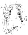
- FIG. 18 shows a perspective view of a painting robot with a robot base 60, which is either stationary or movable on a travel rail.
- two robot parts 61, 62 are rotatably supported on opposite sides, with the two robot parts 61, 62 relative to the common robot base 60 are rotatable about a common, horizontal axis of rotation.
- a proximal robot arm 63 and a distal robot arm 64 are pivotally arranged, the distal robot arm 64 guiding a rotary atomizer 66 via a robot hand axis 65.
- a proximal robotic arm 67 and a distal robotic arm 68 are pivotally mounted on the rotatable robotic part 62, and the distal robotic arm 68 also guides a rotary atomizer 70 via a robot hand axis 69.
- application technique 70 is arranged on the distal robot arm 68, which also applies in the same way to the distal robot arm 64 shown closed.
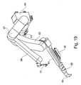
- FIG. 19 shows a modification of the painting robot FIG. 18
- the same reference numerals are used for corresponding details.
- a special feature of this embodiment is that the distal robot arm 68 does not carry a rotary atomizer, but a handle 72 for opening or closing a hood of a motor vehicle body.
- the painting robot thus not only allows the application of paint in this embodiment, but also serves as a handling robot and concretely as a bonnet opener.
- proximal robot arm 67 without the interposition of the robot part 62 is pivoted directly to the robot base 60.
Landscapes
- Engineering & Computer Science (AREA)
- Robotics (AREA)
- Mechanical Engineering (AREA)
- Spray Control Apparatus (AREA)
- Manipulator (AREA)
- Application Of Or Painting With Fluid Materials (AREA)
- Electrostatic Spraying Apparatus (AREA)
- Automobile Manufacture Line, Endless Track Vehicle, Trailer (AREA)
- Details Or Accessories Of Spraying Plant Or Apparatus (AREA)
Priority Applications (1)
| Application Number | Priority Date | Filing Date | Title |
|---|---|---|---|
| PL13005361T PL2698232T3 (pl) | 2008-09-03 | 2009-08-19 | Urządzenie lakiernicze |
Applications Claiming Priority (2)
| Application Number | Priority Date | Filing Date | Title |
|---|---|---|---|
| DE102008045553A DE102008045553A1 (de) | 2008-09-03 | 2008-09-03 | Lackiereinrichtung und zugehöriges Verfahren |
| EP09777972.2A EP2318185B1 (fr) | 2008-09-03 | 2009-08-19 | Dispositif de peinture |
Related Parent Applications (1)
| Application Number | Title | Priority Date | Filing Date |
|---|---|---|---|
| EP09777972.2A Division EP2318185B1 (fr) | 2008-09-03 | 2009-08-19 | Dispositif de peinture |
Publications (3)
| Publication Number | Publication Date |
|---|---|
| EP2698232A2 true EP2698232A2 (fr) | 2014-02-19 |
| EP2698232A3 EP2698232A3 (fr) | 2014-03-12 |
| EP2698232B1 EP2698232B1 (fr) | 2015-04-22 |
Family
ID=41136766
Family Applications (2)
| Application Number | Title | Priority Date | Filing Date |
|---|---|---|---|
| EP09777972.2A Revoked EP2318185B1 (fr) | 2008-09-03 | 2009-08-19 | Dispositif de peinture |
| EP20130005361 Active EP2698232B1 (fr) | 2008-09-03 | 2009-08-19 | Dispositif de peinture |
Family Applications Before (1)
| Application Number | Title | Priority Date | Filing Date |
|---|---|---|---|
| EP09777972.2A Revoked EP2318185B1 (fr) | 2008-09-03 | 2009-08-19 | Dispositif de peinture |
Country Status (8)
| Country | Link |
|---|---|
| US (2) | US8627780B2 (fr) |
| EP (2) | EP2318185B1 (fr) |
| JP (2) | JP2012501820A (fr) |
| CN (2) | CN107097205B (fr) |
| DE (1) | DE102008045553A1 (fr) |
| ES (1) | ES2449395T3 (fr) |
| PL (2) | PL2318185T3 (fr) |
| WO (1) | WO2010025827A1 (fr) |
Cited By (2)
| Publication number | Priority date | Publication date | Assignee | Title |
|---|---|---|---|---|
| CN104858088A (zh) * | 2015-06-04 | 2015-08-26 | 马鞍山市安工大工业技术研究院有限公司 | 一种用于汽车弹簧喷漆的喷漆机器人 |
| US20220339665A1 (en) * | 2019-09-30 | 2022-10-27 | Dürr Systems Ag | Treatment system and treatment method |
Families Citing this family (75)
| Publication number | Priority date | Publication date | Assignee | Title |
|---|---|---|---|---|
| DE102008045553A1 (de) * | 2008-09-03 | 2010-03-04 | Dürr Systems GmbH | Lackiereinrichtung und zugehöriges Verfahren |
| US20100145516A1 (en) * | 2008-12-08 | 2010-06-10 | Illinois Tool Works Inc. | High voltage monitoring system and method for spray coating systems |
| DE102009012140A1 (de) * | 2009-03-06 | 2010-09-09 | Dürr Systems GmbH | Roboteranordnung, insbesondere in einer Lackierkabine |
| CN102596423B (zh) * | 2009-11-06 | 2015-11-25 | 本田技研工业株式会社 | 涂装系统 |
| DE102010018468A1 (de) | 2010-04-27 | 2011-10-27 | Dürr Systems GmbH | Vorrichtung und Verfahren zur Handhabung von vorzugsweise zu beschichtenden Bauteilen |
| DE102010023578B4 (de) * | 2010-06-12 | 2018-02-22 | Abb Ag | Lackieranlage zum Beschichten / Lackieren eines langgestreckten Werkstückes |
| JP2012121105A (ja) * | 2010-12-09 | 2012-06-28 | Yaskawa Electric Corp | 塗装ロボット及び塗装システム |
| DE102011017347A1 (de) | 2011-04-16 | 2012-10-18 | Eisenmann Ag | Behandlungseinheit, Anlage und Verfahren zur Oberflächenbehandlung von Gegenständen |
| JP5418545B2 (ja) * | 2011-06-24 | 2014-02-19 | 株式会社安川電機 | 塗装システム |
| DE102011108262B4 (de) * | 2011-07-25 | 2015-12-17 | Eisenmann Ag | Vorrichtung zum Lackieren von Fahrzeugkarosserien mit einer Vielzahl von gestaltveranderlichen Armen |
| JP5585553B2 (ja) * | 2011-08-01 | 2014-09-10 | 株式会社安川電機 | 塗装システムおよびドア開閉用ロボットの開閉ハンド |
| CN102921581B (zh) * | 2011-08-09 | 2015-07-22 | 株式会社安川电机 | 涂装系统和门开/关机器人的开/关手 |
| EP2556929B1 (fr) * | 2011-08-10 | 2015-02-18 | Kabushiki Kaisha Yaskawa Denki | Système de peinture |
| DE102011121343A1 (de) | 2011-12-16 | 2013-06-20 | Dürr Systems GmbH | Beschichtungsanlage und entsprechendes Betriebsverfahren |
| CN102728508A (zh) * | 2012-07-17 | 2012-10-17 | 昆山华恒焊接股份有限公司 | 机器人涂装系统 |
| DE102013109867A1 (de) | 2012-09-10 | 2014-03-13 | Fanuc Robotics America Corporation | Robotereinsatzgerät zum Lackieren |
| DE102013013038A1 (de) * | 2013-08-05 | 2015-02-05 | Dürr Systems GmbH | Beschichtungsroboter und entsprechendes Beschichtungsverfahren |
| USD755867S1 (en) * | 2013-10-07 | 2016-05-10 | Jorge Juan Garcia Garcia | Telescopic articulated arm |
| US9759089B2 (en) * | 2013-12-10 | 2017-09-12 | General Electric Company | Transportable modular coating systems and methods |
| DE102014000478A1 (de) * | 2014-01-16 | 2015-07-16 | Dürr Systems GmbH | Schutzschildvorrichtung für eine Verfahrschiene |
| US9861998B2 (en) * | 2014-04-07 | 2018-01-09 | Oria Collapsibles, Llc | Assembly for coating an article incorporating robotic subassemblies utilizing articulating spray arms and carousel conveyor with inlet and outlet locations for the article |
| DE102014207275A1 (de) * | 2014-04-15 | 2015-10-15 | Kuka Systems Gmbh | Robotervorrichtung mit einer Linearachse |
| DE102014006651A1 (de) * | 2014-05-07 | 2015-11-12 | Dürr Systems GmbH | Beschichtungsanlage zur Beschichtung von Bauteilen, insbesondere zur Lackierung von Kraftfahrzeugkarosseriebauteilen |
| US9339833B2 (en) * | 2014-05-08 | 2016-05-17 | Ford Motor Company | Compact fluid delivery system for automation |
| KR20200040908A (ko) * | 2014-07-31 | 2020-04-20 | 제이코 에스.피.에이. | 객체의 표면 처리를 위한 스테이션 및 플랜트 |
| KR101702716B1 (ko) * | 2014-10-28 | 2017-02-13 | 김재호 | 회전형 파이프 페인팅 장치 및 그 장치를 이용한 파이프 페인팅 방법 |
| JP6567819B2 (ja) * | 2014-12-09 | 2019-08-28 | 川崎重工業株式会社 | 自動生産システム |
| DE102015003136A1 (de) * | 2015-03-11 | 2016-09-15 | Kuka Roboter Gmbh | Roboterlagerung |
| JP6068548B2 (ja) * | 2015-04-09 | 2017-01-25 | ファナック株式会社 | 線条体を接続する接続部材がアームに配置された多関節ロボット |
| CN104972589B (zh) * | 2015-06-24 | 2017-07-14 | 东莞市松庆智能自动化科技有限公司 | 一种多轴联动式机器人及其自动化浇注系统 |
| WO2017029711A1 (fr) * | 2015-08-18 | 2017-02-23 | 株式会社安川電機 | Système de peinture et procédé de peinture |
| DE102015015089A1 (de) * | 2015-11-20 | 2017-05-24 | Dürr Systems Ag | Überdruckkapselungssystem zum Explosionsschutz und entsprechendes Betriebsverfahren |
| DE102016001073B4 (de) * | 2016-02-02 | 2018-10-25 | Eisenmann Se | Mehrachsroboter sowie Verfahren zu dessen Steuerung bei der Lackierung von Gegenständen |
| DE102016003966A1 (de) * | 2016-04-01 | 2017-10-05 | Dürr Systems Ag | Beschichtungsroboter |
| DE102016004846A1 (de) * | 2016-04-22 | 2017-10-26 | Dürr Systems Ag | Lackiereinheit |
| DE102016014953A1 (de) | 2016-12-14 | 2018-06-14 | Dürr Systems Ag | Lackieranlage und entsprechendes Lackierverfahren |
| DE102016014943A1 (de) | 2016-12-14 | 2018-06-14 | Dürr Systems Ag | Druckkopf mit Temperiereinrichtung |
| DE102016014956A1 (de) | 2016-12-14 | 2018-06-14 | Dürr Systems Ag | Beschichtungseinrichtung und zugehöriges Betriebsverfahren |
| DE102016014946A1 (de) | 2016-12-14 | 2018-06-14 | Dürr Systems Ag | Druckkopf zur Applikation eines Beschichtungsmittels auf ein Bauteil |
| DE102016014947A1 (de) | 2016-12-14 | 2018-06-14 | Dürr Systems Ag | Druckkopf zur Applikation eines Beschichtungsmittels |
| DE102016014952A1 (de) | 2016-12-14 | 2018-06-14 | Dürr Systems Ag | Beschichtungseinrichtung zur Beschichtung von Bauteilen |
| DE102016014919A1 (de) | 2016-12-14 | 2018-06-14 | Dürr Systems Ag | Applikationsvorrichtung und Verfahren zum Applizieren eines Beschichtungsmittels |
| DE102016014951A1 (de) | 2016-12-14 | 2018-06-14 | Dürr Systems Ag | Beschichtungseinrichtung und zugehöriges Betriebsverfahren |
| DE102016014955A1 (de) | 2016-12-14 | 2018-06-14 | Dürr Systems Ag | Beschichtungseinrichtung und entsprechendes Beschichtungsverfahren |
| DE102016014948A1 (de) | 2016-12-14 | 2018-06-14 | Dürr Systems Ag | Druckkopf und zugehöriges Betriebsverfahren |
| DE102016014920A1 (de) | 2016-12-14 | 2018-06-14 | Dürr Systems Ag | Druckkopf mit Verschiebe- und/oder Drehmechanik für zumindest eine Düsenreihe |
| DE102016014944A1 (de) | 2016-12-14 | 2018-06-14 | Dürr Systems Ag | Beschichtungsverfahren und entsprechende Beschichtungseinrichtung |
| CN106628906B (zh) * | 2016-12-26 | 2019-07-26 | 迈赫机器人自动化股份有限公司 | 一种机器人升降输送机 |
| CN107471902A (zh) * | 2017-08-17 | 2017-12-15 | 重庆凌慧科技有限公司 | 一种自动供料笔 |
| JP6900862B2 (ja) * | 2017-09-22 | 2021-07-07 | 株式会社デンソーウェーブ | 移動ロボット |
| CN107803823B (zh) * | 2017-12-01 | 2023-12-12 | 韩山师范学院 | 带机械手的自动装配生产线 |
| CN108058157A (zh) * | 2018-01-29 | 2018-05-22 | 西安优艾智合机器人科技有限公司 | 一种巡检机器人 |
| DE112019002281T5 (de) * | 2018-05-03 | 2021-02-04 | Fanuc America Corporation | Elektrostatische lackiervorrichtung mit roboter |
| USD888521S1 (en) * | 2018-06-19 | 2020-06-30 | William E. Howseman, Jr. | Spray gun elevator |
| USD888522S1 (en) * | 2018-06-19 | 2020-06-30 | William E. Howseman, Jr. | Spray gun elevator |
| EP3685925B1 (fr) * | 2018-08-14 | 2022-10-26 | pentanova cs GmbH | Procédé et dispositif de peinture par pulvérisation d'une pièce à usiner |
| US20200061840A1 (en) * | 2018-08-27 | 2020-02-27 | Ascend Robbotics LLC | Automated construction robot systems and methods |
| DE102019119613A1 (de) * | 2019-07-19 | 2021-01-21 | Bayerische Motoren Werke Aktiengesellschaft | Verfahren zum Lackieren eines Außenhautbauteils eines Kraftfahrzeugs sowie Lackierstation für ein Außenhautbauteil eines Kraftfahrzeugs |
| EP3771522A1 (fr) | 2019-07-30 | 2021-02-03 | Siemens Aktiengesellschaft | Procédé et système de manipulation permettant de manipuler un objet à l'aide d'un robot avec champs vectoriel |
| CN111515063A (zh) * | 2020-05-11 | 2020-08-11 | 镇江蓝舶科技股份有限公司 | 一种基于作业机器人的轨道式涂装设备 |
| CN111561869B (zh) * | 2020-05-22 | 2021-11-23 | 延锋彼欧武汉汽车外饰系统有限公司 | 一种车体空间位置智能检测装置、方法及其应用 |
| JP7396220B2 (ja) * | 2020-07-06 | 2023-12-12 | トヨタ自動車株式会社 | 塗装装置および塗装装置の設置方法 |
| CN111905955B (zh) * | 2020-07-08 | 2021-08-06 | 威海英博特精密机械有限公司 | 一种工业自动化喷漆机器人 |
| TWI768600B (zh) * | 2020-12-17 | 2022-06-21 | 魏榮宗 | 廢氣淨化系統 |
| CN112657737A (zh) * | 2020-12-31 | 2021-04-16 | 深圳元尚实业有限公司 | 一种移动式喷涂平台 |
| DE102021101027A1 (de) * | 2021-01-19 | 2022-07-21 | Dürr Systems Ag | Beschichtungseinrichtung, insbesondere Lackierroboter |
| DE102021205536A1 (de) * | 2021-05-31 | 2022-12-01 | Adidas Ag | Verfahren zum Aufbringen von Materialien auf Schuhe |
| DE102021124215B4 (de) * | 2021-09-20 | 2024-10-31 | Linrob Automation Gmbh | Verfahren zur Kompensation von Positionierungsungenauigkeiten eines Linearroboters und Linearroboter |
| JP7764277B2 (ja) * | 2022-02-28 | 2025-11-05 | 株式会社安川電機 | ドア開閉ロボット、及び、ドア開閉システム |
| JP7153816B1 (ja) * | 2022-03-28 | 2022-10-14 | アーベーベー・シュバイツ・アーゲー | 車体塗装用ロボット |
| EP4458525A4 (fr) * | 2022-11-18 | 2025-04-09 | Korea Advanced Institute of Science and Technology | Robot d'exploration pour l'inspection douaniere d'une cargaison chargée sur un conteneur |
| JP2024151270A (ja) * | 2023-04-11 | 2024-10-24 | 株式会社不二越 | 垂直多関節ロボット |
| DE102024117259A1 (de) * | 2024-06-19 | 2025-12-24 | Dürr Systems Ag | Roboter mit versetzten Achsenebenen |
| WO2026039825A1 (fr) * | 2024-08-16 | 2026-02-19 | The Regents Of The University Of Michigan | Procédé de commande de système de dépôt de matériau multi-robot et ensemble associé |
| KR102855003B1 (ko) * | 2025-01-31 | 2025-09-04 | 동해기계주식회사 | 자동 도장용 로봇 설비 |
Citations (5)
| Publication number | Priority date | Publication date | Assignee | Title |
|---|---|---|---|---|
| DE2915603C2 (de) | 1979-04-18 | 1983-10-27 | Zahnradfabrik Friedrichshafen Ag, 7990 Friedrichshafen | Handhabungsgerät für senkrecht zur Abstützbasis und um eine dazu parallele Schwenkachse erfolgende Lasten-Umsetzmanöver mit dazu quergerichteter Justierbarkeit |
| DE9212718U1 (de) | 1992-09-22 | 1992-11-26 | Kell, Gerhard, 6074 Rödermark | Mehrarmiges, modulares Bewegungssystem für industrielle und allgemeine Anwendung |
| DE69102353T2 (de) | 1990-06-27 | 1994-10-20 | Kobe Steel Ltd | Verfahren zum Lackieren von Autos. |
| DE4430234A1 (de) | 1993-08-25 | 1995-03-02 | Mazda Motor | Verfahren zur Feststellung von Gardinenbildung bei Beschichtungen sowie Beschichtungssystem mit Anwendung des genannten Verfahrens |
| DE69629246T2 (de) | 1995-05-31 | 2004-04-15 | Kawasaki Jukogyo K.K., Kobe | Anordnung für die Aufstellung von Lackierrobotern in einer Lackierstrasse |
Family Cites Families (40)
| Publication number | Priority date | Publication date | Assignee | Title |
|---|---|---|---|---|
| DE10224858B4 (de) * | 2002-06-05 | 2005-07-14 | Kuka Roboter Gmbh | Vorrichtung zum Führen eines Schlauches |
| JPS5895558A (ja) * | 1981-11-30 | 1983-06-07 | Mazda Motor Corp | 自動車ボデイ塗装用ロボツト |
| JPS60860A (ja) * | 1983-06-20 | 1985-01-05 | Toyota Motor Corp | 塗装用ロボツトにおける色替え装置 |
| US4721630A (en) | 1985-07-31 | 1988-01-26 | Honda Giken Kogyo Kabushiki Kaisha | Painting process for inner panel region of motorcar vehicle body and apparatus therefor |
| JPH0247951B2 (ja) * | 1985-10-04 | 1990-10-23 | Honda Motor Co Ltd | Jidoshashatainonaibanbutosohoho |
| US4630567A (en) * | 1985-08-28 | 1986-12-23 | Gmf Robotics Corporation | Spray paint system including paint booth, paint robot apparatus movable therein and rail mechanism for supporting the apparatus thereout |
| JPH026868A (ja) | 1988-06-25 | 1990-01-11 | Taikisha Ltd | 塗装ブースにおける塗装装置設置方法と塗装ブースの一部を構成する塗装機操作ユニット |
| CA1332505C (fr) * | 1989-05-23 | 1994-10-18 | Kenichi Chujyo | Methode et dispositif pour le revetement d'une carrosserie de voiture automobile |
| JPH05200333A (ja) * | 1992-01-27 | 1993-08-10 | Toyota Motor Corp | 自動塗装装置 |
| JPH05302429A (ja) | 1992-02-26 | 1993-11-16 | Shimizu Corp | 吹付け装置および吹付け施工法 |
| FR2710858B1 (fr) * | 1993-10-06 | 1995-12-15 | Sames Sa | Dispositif de projection de produit de revêtement formant machine de toit ou machine latérale. |
| JPH07227556A (ja) | 1994-02-18 | 1995-08-29 | Mesatsuku:Kk | 塗装ロボット用塗装装置およびその操作方法 |
| JPH09308848A (ja) * | 1996-05-20 | 1997-12-02 | Tokico Ltd | 色替え装置及び塗装用ロボット |
| JPH10180178A (ja) * | 1996-12-27 | 1998-07-07 | Sekisui Chem Co Ltd | コーナー用外壁材の塗装方法 |
| FR2777383B1 (fr) | 1998-04-09 | 2000-05-12 | Alsthom Cge Alcatel | Conducteur multicouche a effet de peau reduit |
| FR2777483A1 (fr) | 1998-04-15 | 1999-10-22 | Sames Sa | Procede et installation de projection de produit de revetement |
| JP2000167450A (ja) * | 1998-11-30 | 2000-06-20 | Tokico Ltd | 塗装用ロボット |
| JP2000167451A (ja) * | 1998-12-04 | 2000-06-20 | Toyota Motor Corp | 自動車塗装システム |
| FR2804349B1 (fr) * | 2000-01-31 | 2002-07-19 | Eisenmann France Sarl | Dispositif de pulverisation destine notamment a une cabine de peinture de carrosserie automobile |
| DE10103067A1 (de) | 2001-01-24 | 2002-07-25 | Duerr Systems Gmbh | Beschichtungsmaschine mit einem auswechselbaren Applikationsorgan |
| US6757586B2 (en) * | 2001-09-05 | 2004-06-29 | Abb Automation Inc. | Multiple arm robot arrangement |
| CN101524675B (zh) * | 2002-10-23 | 2013-07-10 | 美国发那科机器人有限公司 | 机器人喷涂装置 |
| JP2004261650A (ja) * | 2003-02-21 | 2004-09-24 | Honda Motor Co Ltd | 保護層形成材の塗布システムおよび塗布方法 |
| GB2422336B (en) * | 2003-02-21 | 2007-04-25 | Honda Motor Co Ltd | Coating system for protective layer forming material |
| JP3885036B2 (ja) * | 2003-03-14 | 2007-02-21 | 本田技研工業株式会社 | 保護層形成材の塗布方法および塗布装置 |
| GB2417090A (en) * | 2003-04-28 | 2006-02-15 | Stephen James Crampton | CMM arm with exoskeleton |
| DE102004033640B4 (de) | 2003-07-18 | 2012-03-29 | Abb As | Farbauftragssystem |
| US8051796B2 (en) * | 2003-10-23 | 2011-11-08 | Fanuc Robotics America, Inc. | Robotic apparatus and method for painting |
| EP1682283B1 (fr) * | 2003-11-06 | 2008-08-06 | Fanuc Robotics America, Inc. | Cabine de peinture robotique compacte |
| KR100495707B1 (ko) * | 2003-12-09 | 2005-06-17 | 대한도장플랜트(주) | 동작 범위 설정이 가능한 도장용 다관절 로봇 |
| DE102004056493A1 (de) * | 2004-06-25 | 2006-01-12 | Dürr Systems GmbH | Beschichtungsanlage und zugehöriges Betriebsverfahren |
| DE102004040162B4 (de) | 2004-08-19 | 2013-10-24 | Eisenmann Ag | Vorrichtung zum Beschichten von Gegenständen |
| DE102005013014A1 (de) * | 2005-03-21 | 2006-10-05 | Dürr Systems GmbH | Beschichtungsanlage und zugehöriges Verfahren |
| US7644571B2 (en) * | 2005-06-01 | 2010-01-12 | Durr Systems, Inc. | Hose conduit element for a paint robot |
| FR2890876B1 (fr) * | 2005-09-19 | 2007-11-30 | Sames Technologies Soc Par Act | Installation de projection de produit de revetement multi-composant |
| DE102006032804A1 (de) | 2006-07-14 | 2008-01-17 | Dürr Systems GmbH | Lackieranlage und zugehöriges Betriebsverfahren |
| BRPI0717421B1 (pt) * | 2006-09-27 | 2020-01-28 | Duerr Systems Gmbh | disposições de pulverizador para máquina de revestimento para revestimento eletrostático em série de peças de trabalho |
| DE102006058350A1 (de) | 2006-12-11 | 2008-06-12 | Dürr Systems GmbH | Beschichtungsanlage und Verfahren zur Serienbeschichtung von Werkstücken |
| DE102007062403A1 (de) * | 2007-12-20 | 2009-06-25 | Abb Ag | Anordnung von Lackierrobotern |
| DE102008045553A1 (de) * | 2008-09-03 | 2010-03-04 | Dürr Systems GmbH | Lackiereinrichtung und zugehöriges Verfahren |
-
2008
- 2008-09-03 DE DE102008045553A patent/DE102008045553A1/de not_active Withdrawn
-
2009
- 2009-08-19 CN CN201610873232.7A patent/CN107097205B/zh active Active
- 2009-08-19 PL PL09777972T patent/PL2318185T3/pl unknown
- 2009-08-19 JP JP2011525434A patent/JP2012501820A/ja active Pending
- 2009-08-19 EP EP09777972.2A patent/EP2318185B1/fr not_active Revoked
- 2009-08-19 ES ES09777972.2T patent/ES2449395T3/es active Active
- 2009-08-19 CN CN200980134501.6A patent/CN102177002B/zh active Active
- 2009-08-19 PL PL13005361T patent/PL2698232T3/pl unknown
- 2009-08-19 EP EP20130005361 patent/EP2698232B1/fr active Active
- 2009-08-19 US US13/062,070 patent/US8627780B2/en active Active
- 2009-08-19 WO PCT/EP2009/006007 patent/WO2010025827A1/fr not_active Ceased
-
2013
- 2013-12-05 US US14/097,567 patent/US9630199B2/en active Active
-
2015
- 2015-05-01 JP JP2015094011A patent/JP6188740B2/ja active Active
Patent Citations (5)
| Publication number | Priority date | Publication date | Assignee | Title |
|---|---|---|---|---|
| DE2915603C2 (de) | 1979-04-18 | 1983-10-27 | Zahnradfabrik Friedrichshafen Ag, 7990 Friedrichshafen | Handhabungsgerät für senkrecht zur Abstützbasis und um eine dazu parallele Schwenkachse erfolgende Lasten-Umsetzmanöver mit dazu quergerichteter Justierbarkeit |
| DE69102353T2 (de) | 1990-06-27 | 1994-10-20 | Kobe Steel Ltd | Verfahren zum Lackieren von Autos. |
| DE9212718U1 (de) | 1992-09-22 | 1992-11-26 | Kell, Gerhard, 6074 Rödermark | Mehrarmiges, modulares Bewegungssystem für industrielle und allgemeine Anwendung |
| DE4430234A1 (de) | 1993-08-25 | 1995-03-02 | Mazda Motor | Verfahren zur Feststellung von Gardinenbildung bei Beschichtungen sowie Beschichtungssystem mit Anwendung des genannten Verfahrens |
| DE69629246T2 (de) | 1995-05-31 | 2004-04-15 | Kawasaki Jukogyo K.K., Kobe | Anordnung für die Aufstellung von Lackierrobotern in einer Lackierstrasse |
Cited By (4)
| Publication number | Priority date | Publication date | Assignee | Title |
|---|---|---|---|---|
| CN104858088A (zh) * | 2015-06-04 | 2015-08-26 | 马鞍山市安工大工业技术研究院有限公司 | 一种用于汽车弹簧喷漆的喷漆机器人 |
| US20220339665A1 (en) * | 2019-09-30 | 2022-10-27 | Dürr Systems Ag | Treatment system and treatment method |
| US12465944B2 (en) * | 2019-09-30 | 2025-11-11 | Dürr Systems Ag | Treatment system and treatment method |
| US12564858B2 (en) | 2019-09-30 | 2026-03-03 | Dürr Systems Ag | Treatment system and treatment method |
Also Published As
| Publication number | Publication date |
|---|---|
| PL2318185T3 (pl) | 2014-05-30 |
| EP2318185A1 (fr) | 2011-05-11 |
| EP2698232B1 (fr) | 2015-04-22 |
| PL2698232T3 (pl) | 2015-09-30 |
| ES2449395T3 (es) | 2014-03-19 |
| JP2012501820A (ja) | 2012-01-26 |
| JP2015166087A (ja) | 2015-09-24 |
| EP2318185B1 (fr) | 2013-12-11 |
| CN107097205A (zh) | 2017-08-29 |
| US9630199B2 (en) | 2017-04-25 |
| WO2010025827A1 (fr) | 2010-03-11 |
| US20140109830A1 (en) | 2014-04-24 |
| US20110166708A1 (en) | 2011-07-07 |
| CN102177002A (zh) | 2011-09-07 |
| DE102008045553A1 (de) | 2010-03-04 |
| CN102177002B (zh) | 2016-10-19 |
| EP2698232A3 (fr) | 2014-03-12 |
| JP6188740B2 (ja) | 2017-08-30 |
| CN107097205B (zh) | 2020-06-19 |
| US8627780B2 (en) | 2014-01-14 |
Similar Documents
| Publication | Publication Date | Title |
|---|---|---|
| EP2318185B1 (fr) | Dispositif de peinture | |
| EP2919917B1 (fr) | Robot d'application muni d'une unité de raccordement pour différents applicateurs | |
| EP1745858B1 (fr) | Procédé de revêtement et dispositif correspondant | |
| EP2040854B1 (fr) | Installation de mise en peinture et procédé de fonctionnement associé | |
| EP2101926B1 (fr) | Installation de revêtement et procédé de revêtement en série de pièces | |
| EP2403689A2 (fr) | Ensemble robotique utilisé notamment dans une cabine de peinture | |
| EP2160253B1 (fr) | Zone de revêtement dotée de rails de guidage inclinés | |
| DE60123924T2 (de) | Spritzvorrichtung, insbesondere für eine Lackierkabine für Fahrzeugkarosserien | |
| WO2017008889A1 (fr) | Robot pour installation de revêtement, en particulier robot manipulateur | |
| WO2015018512A1 (fr) | Robot de revêtement et procédé de revêtement correspondant | |
| EP2089164B1 (fr) | Pulverisateur universel et procede correspondant permettant son fonctionnement | |
| EP2791008B1 (fr) | Dispositif de revêtement et procédé correspondant | |
| WO2017182604A1 (fr) | Unité de mise en peinture | |
| EP2595760B1 (fr) | Unité de traitement et installation de traitement des surfaces d'objets | |
| EP0392267A2 (fr) | Machine pour appliquer un revêtement sur des carrosseries automobiles | |
| EP1704924A1 (fr) | Dispositif et procédé de revêtement | |
| EP1419824B1 (fr) | Dispositif de revêtement de pièces avec poudre | |
| DE102016003916A1 (de) | Lackierstation und zugehöriges Betriebsverfahren | |
| DE102008035641A1 (de) | Manipulator und Verfahren zum Reinigen eines mehrere über Gelenke verbundene Glieder aufweisenden Manipulators | |
| DE102016001073B4 (de) | Mehrachsroboter sowie Verfahren zu dessen Steuerung bei der Lackierung von Gegenständen | |
| DE10006865B4 (de) | Verfahren zum Lackieren von Fahrzeugkarosserien |
Legal Events
| Date | Code | Title | Description |
|---|---|---|---|
| PUAL | Search report despatched |
Free format text: ORIGINAL CODE: 0009013 |
|
| AC | Divisional application: reference to earlier application |
Ref document number: 2318185 Country of ref document: EP Kind code of ref document: P |
|
| AK | Designated contracting states |
Kind code of ref document: A2 Designated state(s): AT BE BG CH CY CZ DE DK EE ES FI FR GB GR HR HU IE IS IT LI LT LU LV MC MK MT NL NO PL PT RO SE SI SK SM TR |
|
| PUAI | Public reference made under article 153(3) epc to a published international application that has entered the european phase |
Free format text: ORIGINAL CODE: 0009012 |
|
| AK | Designated contracting states |
Kind code of ref document: A3 Designated state(s): AT BE BG CH CY CZ DE DK EE ES FI FR GB GR HR HU IE IS IT LI LT LU LV MC MK MT NL NO PL PT RO SE SI SK SM TR |
|
| RIC1 | Information provided on ipc code assigned before grant |
Ipc: B25J 19/00 20060101ALI20140206BHEP Ipc: B25J 5/02 20060101AFI20140206BHEP Ipc: B25J 9/04 20060101ALI20140206BHEP Ipc: B05B 15/12 20060101ALI20140206BHEP Ipc: B25J 9/00 20060101ALI20140206BHEP Ipc: B05B 13/04 20060101ALI20140206BHEP |
|
| 17P | Request for examination filed |
Effective date: 20140818 |
|
| RBV | Designated contracting states (corrected) |
Designated state(s): AT BE BG CH CY CZ DE DK EE ES FI FR GB GR HR HU IE IS IT LI LT LU LV MC MK MT NL NO PL PT RO SE SI SK SM TR |
|
| GRAP | Despatch of communication of intention to grant a patent |
Free format text: ORIGINAL CODE: EPIDOSNIGR1 |
|
| GRAS | Grant fee paid |
Free format text: ORIGINAL CODE: EPIDOSNIGR3 |
|
| GRAA | (expected) grant |
Free format text: ORIGINAL CODE: 0009210 |
|
| INTG | Intention to grant announced |
Effective date: 20150302 |
|
| AC | Divisional application: reference to earlier application |
Ref document number: 2318185 Country of ref document: EP Kind code of ref document: P |
|
| AK | Designated contracting states |
Kind code of ref document: B1 Designated state(s): AT BE BG CH CY CZ DE DK EE ES FI FR GB GR HR HU IE IS IT LI LT LU LV MC MK MT NL NO PL PT RO SE SI SK SM TR |
|
| REG | Reference to a national code |
Ref country code: GB Ref legal event code: FG4D Free format text: NOT ENGLISH |
|
| REG | Reference to a national code |
Ref country code: CH Ref legal event code: EP |
|
| REG | Reference to a national code |
Ref country code: AT Ref legal event code: REF Ref document number: 722924 Country of ref document: AT Kind code of ref document: T Effective date: 20150515 |
|
| REG | Reference to a national code |
Ref country code: IE Ref legal event code: FG4D Free format text: LANGUAGE OF EP DOCUMENT: GERMAN |
|
| REG | Reference to a national code |
Ref country code: DE Ref legal event code: R096 Ref document number: 502009010946 Country of ref document: DE Effective date: 20150603 |
|
| REG | Reference to a national code |
Ref country code: SE Ref legal event code: TRGR |
|
| REG | Reference to a national code |
Ref country code: NL Ref legal event code: VDEP Effective date: 20150422 |
|
| REG | Reference to a national code |
Ref country code: NO Ref legal event code: T2 Effective date: 20150422 |
|
| REG | Reference to a national code |
Ref country code: LT Ref legal event code: MG4D |
|
| PG25 | Lapsed in a contracting state [announced via postgrant information from national office to epo] |
Ref country code: NL Free format text: LAPSE BECAUSE OF FAILURE TO SUBMIT A TRANSLATION OF THE DESCRIPTION OR TO PAY THE FEE WITHIN THE PRESCRIBED TIME-LIMIT Effective date: 20150422 |
|
| REG | Reference to a national code |
Ref country code: PL Ref legal event code: T3 |
|
| PG25 | Lapsed in a contracting state [announced via postgrant information from national office to epo] |
Ref country code: ES Free format text: LAPSE BECAUSE OF FAILURE TO SUBMIT A TRANSLATION OF THE DESCRIPTION OR TO PAY THE FEE WITHIN THE PRESCRIBED TIME-LIMIT Effective date: 20150422 Ref country code: FI Free format text: LAPSE BECAUSE OF FAILURE TO SUBMIT A TRANSLATION OF THE DESCRIPTION OR TO PAY THE FEE WITHIN THE PRESCRIBED TIME-LIMIT Effective date: 20150422 Ref country code: HR Free format text: LAPSE BECAUSE OF FAILURE TO SUBMIT A TRANSLATION OF THE DESCRIPTION OR TO PAY THE FEE WITHIN THE PRESCRIBED TIME-LIMIT Effective date: 20150422 Ref country code: LT Free format text: LAPSE BECAUSE OF FAILURE TO SUBMIT A TRANSLATION OF THE DESCRIPTION OR TO PAY THE FEE WITHIN THE PRESCRIBED TIME-LIMIT Effective date: 20150422 Ref country code: PT Free format text: LAPSE BECAUSE OF FAILURE TO SUBMIT A TRANSLATION OF THE DESCRIPTION OR TO PAY THE FEE WITHIN THE PRESCRIBED TIME-LIMIT Effective date: 20150824 |
|
| PG25 | Lapsed in a contracting state [announced via postgrant information from national office to epo] |
Ref country code: IS Free format text: LAPSE BECAUSE OF FAILURE TO SUBMIT A TRANSLATION OF THE DESCRIPTION OR TO PAY THE FEE WITHIN THE PRESCRIBED TIME-LIMIT Effective date: 20150822 Ref country code: GR Free format text: LAPSE BECAUSE OF FAILURE TO SUBMIT A TRANSLATION OF THE DESCRIPTION OR TO PAY THE FEE WITHIN THE PRESCRIBED TIME-LIMIT Effective date: 20150723 Ref country code: LV Free format text: LAPSE BECAUSE OF FAILURE TO SUBMIT A TRANSLATION OF THE DESCRIPTION OR TO PAY THE FEE WITHIN THE PRESCRIBED TIME-LIMIT Effective date: 20150422 |
|
| REG | Reference to a national code |
Ref country code: DE Ref legal event code: R097 Ref document number: 502009010946 Country of ref document: DE |
|
| PG25 | Lapsed in a contracting state [announced via postgrant information from national office to epo] |
Ref country code: DK Free format text: LAPSE BECAUSE OF FAILURE TO SUBMIT A TRANSLATION OF THE DESCRIPTION OR TO PAY THE FEE WITHIN THE PRESCRIBED TIME-LIMIT Effective date: 20150422 Ref country code: EE Free format text: LAPSE BECAUSE OF FAILURE TO SUBMIT A TRANSLATION OF THE DESCRIPTION OR TO PAY THE FEE WITHIN THE PRESCRIBED TIME-LIMIT Effective date: 20150422 |
|
| PLBE | No opposition filed within time limit |
Free format text: ORIGINAL CODE: 0009261 |
|
| STAA | Information on the status of an ep patent application or granted ep patent |
Free format text: STATUS: NO OPPOSITION FILED WITHIN TIME LIMIT |
|
| PG25 | Lapsed in a contracting state [announced via postgrant information from national office to epo] |
Ref country code: SK Free format text: LAPSE BECAUSE OF FAILURE TO SUBMIT A TRANSLATION OF THE DESCRIPTION OR TO PAY THE FEE WITHIN THE PRESCRIBED TIME-LIMIT Effective date: 20150422 Ref country code: RO Free format text: LAPSE BECAUSE OF NON-PAYMENT OF DUE FEES Effective date: 20150422 |
|
| 26N | No opposition filed |
Effective date: 20160125 |
|
| PG25 | Lapsed in a contracting state [announced via postgrant information from national office to epo] |
Ref country code: MC Free format text: LAPSE BECAUSE OF FAILURE TO SUBMIT A TRANSLATION OF THE DESCRIPTION OR TO PAY THE FEE WITHIN THE PRESCRIBED TIME-LIMIT Effective date: 20150422 Ref country code: LU Free format text: LAPSE BECAUSE OF FAILURE TO SUBMIT A TRANSLATION OF THE DESCRIPTION OR TO PAY THE FEE WITHIN THE PRESCRIBED TIME-LIMIT Effective date: 20150819 |
|
| REG | Reference to a national code |
Ref country code: CH Ref legal event code: PL |
|
| GBPC | Gb: european patent ceased through non-payment of renewal fee |
Effective date: 20150819 |
|
| PG25 | Lapsed in a contracting state [announced via postgrant information from national office to epo] |
Ref country code: CH Free format text: LAPSE BECAUSE OF NON-PAYMENT OF DUE FEES Effective date: 20150831 Ref country code: LI Free format text: LAPSE BECAUSE OF NON-PAYMENT OF DUE FEES Effective date: 20150831 |
|
| PG25 | Lapsed in a contracting state [announced via postgrant information from national office to epo] |
Ref country code: SI Free format text: LAPSE BECAUSE OF FAILURE TO SUBMIT A TRANSLATION OF THE DESCRIPTION OR TO PAY THE FEE WITHIN THE PRESCRIBED TIME-LIMIT Effective date: 20150422 |
|
| REG | Reference to a national code |
Ref country code: IE Ref legal event code: MM4A |
|
| PG25 | Lapsed in a contracting state [announced via postgrant information from national office to epo] |
Ref country code: GB Free format text: LAPSE BECAUSE OF NON-PAYMENT OF DUE FEES Effective date: 20150819 Ref country code: IE Free format text: LAPSE BECAUSE OF NON-PAYMENT OF DUE FEES Effective date: 20150819 |
|
| REG | Reference to a national code |
Ref country code: FR Ref legal event code: PLFP Year of fee payment: 8 |
|
| REG | Reference to a national code |
Ref country code: DE Ref legal event code: R082 Ref document number: 502009010946 Country of ref document: DE Representative=s name: V. BEZOLD & PARTNER PATENTANWAELTE - PARTG MBB, DE Ref country code: DE Ref legal event code: R081 Ref document number: 502009010946 Country of ref document: DE Owner name: DUERR SYSTEMS AG, DE Free format text: FORMER OWNER: DUERR SYSTEMS GMBH, 74321 BIETIGHEIM-BISSINGEN, DE |
|
| REG | Reference to a national code |
Ref country code: AT Ref legal event code: MM01 Ref document number: 722924 Country of ref document: AT Kind code of ref document: T Effective date: 20150819 |
|
| PG25 | Lapsed in a contracting state [announced via postgrant information from national office to epo] |
Ref country code: AT Free format text: LAPSE BECAUSE OF NON-PAYMENT OF DUE FEES Effective date: 20150819 |
|
| REG | Reference to a national code |
Ref country code: DE Ref legal event code: R082 Ref document number: 502009010946 Country of ref document: DE Representative=s name: V. BEZOLD & PARTNER PATENTANWAELTE - PARTG MBB, DE Ref country code: DE Ref legal event code: R081 Ref document number: 502009010946 Country of ref document: DE Owner name: DUERR SYSTEMS AG, DE Free format text: FORMER OWNER: DUERR SYSTEMS AG, 74321 BIETIGHEIM-BISSINGEN, DE |
|
| PG25 | Lapsed in a contracting state [announced via postgrant information from national office to epo] |
Ref country code: MT Free format text: LAPSE BECAUSE OF FAILURE TO SUBMIT A TRANSLATION OF THE DESCRIPTION OR TO PAY THE FEE WITHIN THE PRESCRIBED TIME-LIMIT Effective date: 20150422 |
|
| PG25 | Lapsed in a contracting state [announced via postgrant information from national office to epo] |
Ref country code: BG Free format text: LAPSE BECAUSE OF FAILURE TO SUBMIT A TRANSLATION OF THE DESCRIPTION OR TO PAY THE FEE WITHIN THE PRESCRIBED TIME-LIMIT Effective date: 20150422 Ref country code: HU Free format text: LAPSE BECAUSE OF FAILURE TO SUBMIT A TRANSLATION OF THE DESCRIPTION OR TO PAY THE FEE WITHIN THE PRESCRIBED TIME-LIMIT; INVALID AB INITIO Effective date: 20090819 Ref country code: SM Free format text: LAPSE BECAUSE OF FAILURE TO SUBMIT A TRANSLATION OF THE DESCRIPTION OR TO PAY THE FEE WITHIN THE PRESCRIBED TIME-LIMIT Effective date: 20150422 |
|
| PG25 | Lapsed in a contracting state [announced via postgrant information from national office to epo] |
Ref country code: CY Free format text: LAPSE BECAUSE OF FAILURE TO SUBMIT A TRANSLATION OF THE DESCRIPTION OR TO PAY THE FEE WITHIN THE PRESCRIBED TIME-LIMIT Effective date: 20150422 |
|
| PG25 | Lapsed in a contracting state [announced via postgrant information from national office to epo] |
Ref country code: BE Free format text: LAPSE BECAUSE OF NON-PAYMENT OF DUE FEES Effective date: 20150831 |
|
| REG | Reference to a national code |
Ref country code: FR Ref legal event code: PLFP Year of fee payment: 9 |
|
| PG25 | Lapsed in a contracting state [announced via postgrant information from national office to epo] |
Ref country code: MK Free format text: LAPSE BECAUSE OF FAILURE TO SUBMIT A TRANSLATION OF THE DESCRIPTION OR TO PAY THE FEE WITHIN THE PRESCRIBED TIME-LIMIT Effective date: 20150422 Ref country code: TR Free format text: LAPSE BECAUSE OF FAILURE TO SUBMIT A TRANSLATION OF THE DESCRIPTION OR TO PAY THE FEE WITHIN THE PRESCRIBED TIME-LIMIT Effective date: 20150422 |
|
| REG | Reference to a national code |
Ref country code: FR Ref legal event code: PLFP Year of fee payment: 10 |
|
| P01 | Opt-out of the competence of the unified patent court (upc) registered |
Effective date: 20230512 |
|
| PGFP | Annual fee paid to national office [announced via postgrant information from national office to epo] |
Ref country code: DE Payment date: 20250820 Year of fee payment: 17 |
|
| PGFP | Annual fee paid to national office [announced via postgrant information from national office to epo] |
Ref country code: NO Payment date: 20250826 Year of fee payment: 17 |
|
| PGFP | Annual fee paid to national office [announced via postgrant information from national office to epo] |
Ref country code: IT Payment date: 20250825 Year of fee payment: 17 Ref country code: PL Payment date: 20250807 Year of fee payment: 17 |
|
| PGFP | Annual fee paid to national office [announced via postgrant information from national office to epo] |
Ref country code: FR Payment date: 20250829 Year of fee payment: 17 |
|
| PGFP | Annual fee paid to national office [announced via postgrant information from national office to epo] |
Ref country code: SE Payment date: 20250820 Year of fee payment: 17 |
|
| PGFP | Annual fee paid to national office [announced via postgrant information from national office to epo] |
Ref country code: CZ Payment date: 20250808 Year of fee payment: 17 |