EP2698232A2 - Painting device - Google Patents
Painting device Download PDFInfo
- Publication number
- EP2698232A2 EP2698232A2 EP13005361.4A EP13005361A EP2698232A2 EP 2698232 A2 EP2698232 A2 EP 2698232A2 EP 13005361 A EP13005361 A EP 13005361A EP 2698232 A2 EP2698232 A2 EP 2698232A2
- Authority
- EP
- European Patent Office
- Prior art keywords
- robot
- painting
- arm
- rotatable
- verfahrschiene
- Prior art date
- Legal status (The legal status is an assumption and is not a legal conclusion. Google has not performed a legal analysis and makes no representation as to the accuracy of the status listed.)
- Granted
Links
- 238000010422 painting Methods 0.000 title claims description 274
- 239000003973 paint Substances 0.000 claims abstract description 74
- 239000007921 spray Substances 0.000 claims abstract description 21
- 239000003795 chemical substances by application Substances 0.000 claims abstract description 5
- 238000000034 method Methods 0.000 claims description 20
- 210000002310 elbow joint Anatomy 0.000 claims description 11
- 230000033001 locomotion Effects 0.000 claims description 9
- 238000005516 engineering process Methods 0.000 claims description 8
- 239000011248 coating agent Substances 0.000 claims description 7
- 239000003599 detergent Substances 0.000 claims description 5
- 239000000835 fiber Substances 0.000 claims description 5
- 230000007935 neutral effect Effects 0.000 claims description 5
- 238000005452 bending Methods 0.000 claims description 4
- 230000001276 controlling effect Effects 0.000 claims description 4
- 239000008199 coating composition Substances 0.000 claims description 3
- 239000003570 air Substances 0.000 claims description 2
- 230000001105 regulatory effect Effects 0.000 claims description 2
- 239000006199 nebulizer Substances 0.000 claims 2
- 238000009434 installation Methods 0.000 abstract description 5
- 238000011010 flushing procedure Methods 0.000 abstract 1
- 238000012360 testing method Methods 0.000 description 10
- 238000004519 manufacturing process Methods 0.000 description 5
- 238000006073 displacement reaction Methods 0.000 description 4
- 210000001503 joint Anatomy 0.000 description 4
- 238000000576 coating method Methods 0.000 description 3
- 238000011179 visual inspection Methods 0.000 description 3
- 210000000707 wrist Anatomy 0.000 description 3
- 230000001588 bifunctional effect Effects 0.000 description 2
- 238000006243 chemical reaction Methods 0.000 description 2
- 238000004140 cleaning Methods 0.000 description 2
- 238000004851 dishwashing Methods 0.000 description 2
- 239000007788 liquid Substances 0.000 description 2
- 238000012423 maintenance Methods 0.000 description 2
- 238000012986 modification Methods 0.000 description 2
- 230000004048 modification Effects 0.000 description 2
- 238000007591 painting process Methods 0.000 description 2
- 230000005540 biological transmission Effects 0.000 description 1
- 230000006835 compression Effects 0.000 description 1
- 238000007906 compression Methods 0.000 description 1
- 238000010276 construction Methods 0.000 description 1
- 230000001419 dependent effect Effects 0.000 description 1
- 238000013461 design Methods 0.000 description 1
- 238000011161 development Methods 0.000 description 1
- 230000018109 developmental process Effects 0.000 description 1
- 230000009977 dual effect Effects 0.000 description 1
- 230000005611 electricity Effects 0.000 description 1
- 238000009503 electrostatic coating Methods 0.000 description 1
- 238000011990 functional testing Methods 0.000 description 1
- 239000004922 lacquer Substances 0.000 description 1
- 238000011022 operating instruction Methods 0.000 description 1
- 239000002245 particle Substances 0.000 description 1
- 239000000843 powder Substances 0.000 description 1
- 239000007787 solid Substances 0.000 description 1
- 239000002904 solvent Substances 0.000 description 1
Images


Classifications
-
- B—PERFORMING OPERATIONS; TRANSPORTING
- B05—SPRAYING OR ATOMISING IN GENERAL; APPLYING FLUENT MATERIALS TO SURFACES, IN GENERAL
- B05B—SPRAYING APPARATUS; ATOMISING APPARATUS; NOZZLES
- B05B13/00—Machines or plants for applying liquids or other fluent materials to surfaces of objects or other work by spraying, not covered by groups B05B1/00 - B05B11/00
-
- B—PERFORMING OPERATIONS; TRANSPORTING
- B25—HAND TOOLS; PORTABLE POWER-DRIVEN TOOLS; MANIPULATORS
- B25J—MANIPULATORS; CHAMBERS PROVIDED WITH MANIPULATION DEVICES
- B25J5/00—Manipulators mounted on wheels or on carriages
- B25J5/02—Manipulators mounted on wheels or on carriages travelling along a guideway
-
- B—PERFORMING OPERATIONS; TRANSPORTING
- B05—SPRAYING OR ATOMISING IN GENERAL; APPLYING FLUENT MATERIALS TO SURFACES, IN GENERAL
- B05B—SPRAYING APPARATUS; ATOMISING APPARATUS; NOZZLES
- B05B13/00—Machines or plants for applying liquids or other fluent materials to surfaces of objects or other work by spraying, not covered by groups B05B1/00 - B05B11/00
- B05B13/02—Means for supporting work; Arrangement or mounting of spray heads; Adaptation or arrangement of means for feeding work
- B05B13/04—Means for supporting work; Arrangement or mounting of spray heads; Adaptation or arrangement of means for feeding work the spray heads being moved during spraying operation
- B05B13/0431—Means for supporting work; Arrangement or mounting of spray heads; Adaptation or arrangement of means for feeding work the spray heads being moved during spraying operation with spray heads moved by robots or articulated arms, e.g. for applying liquid or other fluent material to 3D-surfaces
-
- B—PERFORMING OPERATIONS; TRANSPORTING
- B05—SPRAYING OR ATOMISING IN GENERAL; APPLYING FLUENT MATERIALS TO SURFACES, IN GENERAL
- B05B—SPRAYING APPARATUS; ATOMISING APPARATUS; NOZZLES
- B05B13/00—Machines or plants for applying liquids or other fluent materials to surfaces of objects or other work by spraying, not covered by groups B05B1/00 - B05B11/00
- B05B13/02—Means for supporting work; Arrangement or mounting of spray heads; Adaptation or arrangement of means for feeding work
- B05B13/04—Means for supporting work; Arrangement or mounting of spray heads; Adaptation or arrangement of means for feeding work the spray heads being moved during spraying operation
- B05B13/0447—Installation or apparatus for applying liquid or other fluent material to conveyed separate articles
- B05B13/0452—Installation or apparatus for applying liquid or other fluent material to conveyed separate articles the conveyed articles being vehicle bodies
-
- B—PERFORMING OPERATIONS; TRANSPORTING
- B05—SPRAYING OR ATOMISING IN GENERAL; APPLYING FLUENT MATERIALS TO SURFACES, IN GENERAL
- B05B—SPRAYING APPARATUS; ATOMISING APPARATUS; NOZZLES
- B05B16/00—Spray booths
-
- B—PERFORMING OPERATIONS; TRANSPORTING
- B05—SPRAYING OR ATOMISING IN GENERAL; APPLYING FLUENT MATERIALS TO SURFACES, IN GENERAL
- B05B—SPRAYING APPARATUS; ATOMISING APPARATUS; NOZZLES
- B05B16/00—Spray booths
- B05B16/40—Construction elements specially adapted therefor, e.g. floors, walls or ceilings
-
- B—PERFORMING OPERATIONS; TRANSPORTING
- B05—SPRAYING OR ATOMISING IN GENERAL; APPLYING FLUENT MATERIALS TO SURFACES, IN GENERAL
- B05B—SPRAYING APPARATUS; ATOMISING APPARATUS; NOZZLES
- B05B5/00—Electrostatic spraying apparatus; Spraying apparatus with means for charging the spray electrically; Apparatus for spraying liquids or other fluent materials by other electric means
- B05B5/08—Plant for applying liquids or other fluent materials to objects
-
- B—PERFORMING OPERATIONS; TRANSPORTING
- B25—HAND TOOLS; PORTABLE POWER-DRIVEN TOOLS; MANIPULATORS
- B25J—MANIPULATORS; CHAMBERS PROVIDED WITH MANIPULATION DEVICES
- B25J19/00—Accessories fitted to manipulators, e.g. for monitoring, for viewing; Safety devices combined with or specially adapted for use in connection with manipulators
- B25J19/0025—Means for supplying energy to the end effector
- B25J19/0029—Means for supplying energy to the end effector arranged within the different robot elements
-
- B—PERFORMING OPERATIONS; TRANSPORTING
- B25—HAND TOOLS; PORTABLE POWER-DRIVEN TOOLS; MANIPULATORS
- B25J—MANIPULATORS; CHAMBERS PROVIDED WITH MANIPULATION DEVICES
- B25J9/00—Programme-controlled manipulators
-
- B—PERFORMING OPERATIONS; TRANSPORTING
- B25—HAND TOOLS; PORTABLE POWER-DRIVEN TOOLS; MANIPULATORS
- B25J—MANIPULATORS; CHAMBERS PROVIDED WITH MANIPULATION DEVICES
- B25J9/00—Programme-controlled manipulators
- B25J9/0009—Constructional details, e.g. manipulator supports, bases
-
- B—PERFORMING OPERATIONS; TRANSPORTING
- B25—HAND TOOLS; PORTABLE POWER-DRIVEN TOOLS; MANIPULATORS
- B25J—MANIPULATORS; CHAMBERS PROVIDED WITH MANIPULATION DEVICES
- B25J9/00—Programme-controlled manipulators
- B25J9/0084—Programme-controlled manipulators comprising a plurality of manipulators
-
- B—PERFORMING OPERATIONS; TRANSPORTING
- B25—HAND TOOLS; PORTABLE POWER-DRIVEN TOOLS; MANIPULATORS
- B25J—MANIPULATORS; CHAMBERS PROVIDED WITH MANIPULATION DEVICES
- B25J9/00—Programme-controlled manipulators
- B25J9/0093—Programme-controlled manipulators co-operating with conveyor means
-
- B—PERFORMING OPERATIONS; TRANSPORTING
- B25—HAND TOOLS; PORTABLE POWER-DRIVEN TOOLS; MANIPULATORS
- B25J—MANIPULATORS; CHAMBERS PROVIDED WITH MANIPULATION DEVICES
- B25J9/00—Programme-controlled manipulators
- B25J9/02—Programme-controlled manipulators characterised by movement of the arms, e.g. cartesian coordinate type
- B25J9/04—Programme-controlled manipulators characterised by movement of the arms, e.g. cartesian coordinate type by rotating at least one arm, excluding the head movement itself, e.g. cylindrical coordinate type or polar coordinate type
- B25J9/046—Revolute coordinate type
Landscapes
- Engineering & Computer Science (AREA)
- Robotics (AREA)
- Mechanical Engineering (AREA)
- Spray Control Apparatus (AREA)
- Manipulator (AREA)
- Automobile Manufacture Line, Endless Track Vehicle, Trailer (AREA)
- Details Or Accessories Of Spraying Plant Or Apparatus (AREA)
- Electrostatic Spraying Apparatus (AREA)
- Application Of Or Painting With Fluid Materials (AREA)
Abstract
Description
Die Erfindung betrifft eine Lackiereinrichtung zur Lackierung von Bauteilen, insbesondere zur Lackierung von Kraftfahrzeugkarosserien oder deren Teilen. Weiterhin betrifft die Erfindung ein zugehöriges Verfahren zum Herstellen, Testen und/oder Montieren einer Lackiereinrichtung.The invention relates to a painting device for painting components, in particular for painting motor vehicle bodies or parts thereof. Furthermore, the invention relates to an associated method for producing, testing and / or mounting a painting device.
In modernen Lackieranlagen zur Lackierung von Kraftfahrzeugkarosserien werden mehrachsige Lackierroboter eingesetzt, die als Applikationsgerät beispielsweise einen Rotationszerstäuber aufweisen. Die Ansteuerung des Lackierroboters erfolgt hierbei durch eine Robotersteuerung, die meist außerhalb der Lackierkabine in einem Steuerschrank angeordnet ist und bei der Montage der Lackieranlage mit dem Lackierroboter verbunden wird. Darüber hinaus müssen bei der Montage des Lackierroboters auch die verschiedenen Versorgungsleitungen für die zum Betrieb des Lackierroboters erforderlichen Medien (z.B. Druckluft, Lacke, Spülmittel) angeschlossen werden. Diese herkömmlichen Lackieranlagen weisen verschiedene Nachteile auf, wie im Folgenden ausgeführt wird.In modern paint shops for painting motor vehicle bodies multiaxial painting robots are used, which have as an application device, for example, a rotary atomizer. The control of the painting robot takes place here by a robot controller, which is usually arranged outside the painting booth in a control cabinet and is connected to the painting robot during assembly of the paint shop. In addition, during installation of the painting robot, the various supply lines for the media required for operation of the painting robot (for example compressed air, paints, dishwashing liquid) must also be connected. These conventional painting plants have various disadvantages, as will be explained below.
Zum Einen erfordert der Anschluss des Lackierroboters bei der Endmontage einen erheblichen personellen Aufwand, was die Montagekosten erhöht. Darüber hinaus ist auch eine bestimmte Montagezeit erforderlich, was bei einer Umrüstung einer bestehenden Lackieranlage eine entsprechende Umrüst- und Stillstandszeit der Lackieranlage bedingt, was zu Produktionsausfällen führen kann.On the one hand, the connection of the painting robot during final assembly requires a considerable amount of personnel, which increases assembly costs. In addition, a certain assembly time is required, resulting in a conversion of an existing paint shop a corresponding conversion and downtime of the paint shop due, which can lead to production losses.
Zum Anderen können bei der Endmontage des Lackierroboters Fehler beim Anschluss an die Robotersteuerung oder beim Anschluss der Versorgungsleitungen auftreten, so dass der Lackierroboter nach der Endmontage einem aufwändigen Funktionstest unterzogen werden muss, wobei die Umrüstzeit und die entsprechende Stillstandszeit der Lackieranlage durch die zum Testen erforderliche Zeit verlängert wird.On the other hand, errors may occur during the final assembly of the painting robot when connecting to the robot controller or when connecting the supply lines, so that the painting robot after the final assembly must undergo a complex functional test, the changeover time and the corresponding downtime of the paint shop by the time required for testing is extended.
Ferner ist zum Stand der Technik hinzuweisen auf
Der Erfindung liegt deshalb die Aufgabe zugrunde, eine entsprechend verbesserte Lackiereinrichtung und ein zugehöriges Verfahren zu schaffen.The invention is therefore based on the object to provide a correspondingly improved painting and an associated method.
Zum Einen ist es wünschenswert, die bei der Endmontage des Lackierroboters beim Kunden erforderliche Montagezeit zu verringern, was zu einer entsprechend verkürzten Stillstandsdauer der Lackieranlage führt.On the one hand, it is desirable to reduce the assembly time required by the customer during the final assembly of the painting robot, which leads to a correspondingly shortened downtime of the painting installation.
Zum Anderen zielt die Erfindung darauf ab, Montagefehler bei der Endmontage des Lackierroboters in der Lackieranlage nach Möglichkeit zu vermeiden.On the other hand, the invention aims to avoid assembly errors in the final assembly of the painting robot in the paint shop, if possible.
Diese Aufgabe wird durch eine erfindungsgemäße Lackiereinrichtung und durch ein entsprechendes Verfahren gemäß den nebengeordneten Ansprüchen gelöst.This object is achieved by a painting device according to the invention and by a corresponding method according to the independent claims.
Die Erfindung umfasst die allgemeine technische Lehre, den Lackierroboter vormontiert als fertiges Modul mit der Robotersteuerung und einer mechanischen Abstützung auszuliefern, so dass das vormontierte Modul dann beim Kunden in der Lackieranlage einfach und ohne große Montagezeit endmontiert werden kann.The invention comprises the general technical teaching to deliver the painting robot pre-assembled as a finished module with the robot control and a mechanical support, so that the preassembled module then at the customer in the paint shop can be easily assembled without great installation time.
Die erfindungsgemäße Lackiereinrichtung weist vorzugsweise einen mehrachsigen Lackierroboter auf, wobei derartige Lackierroboter an sich aus dem Stand der Technik beschrieben sind und deshalb nicht näher beschrieben werden müssen. Es ist deshalb lediglich kurz zu erwähnen, dass der erfindungsgemäße Lackierroboter einschließlich einer mehrachsigen Roboterhandachse vorzugsweise 5, 6, 7 oder 8 bewegliche Achsen aufweist. Der im Rahmen der Erfindung verwendete Begriff eines Lackierroboters ist also in dem bevorzugten Ausführungsbeispiel zu unterscheiden von herkömmlichen Dachmaschinen oder Seitenmaschinen, die ebenfalls zur Lackierung von Kraftfahrzeugkarosserien eingesetzt werden.The painting device according to the invention preferably has a multi-axis painting robot, wherein such painting robots are described per se from the prior art and therefore need not be described in detail. It is therefore only briefly to mention that the painting robot according to the invention including a multi-axis robot hand axis preferably has 5, 6, 7 or 8 movable axes. The term used in the invention of a painting robot is thus in the preferred embodiment to distinguish from conventional roofing machines or side machines, which are also used for painting motor vehicle bodies.
Der Lackierroboter führt als Applikationsgerät vorzugsweise einen Rotationszerstäuber, jedoch sind im Rahmen der Erfindung auch andere Zerstäubertypen möglich, wie beispielsweise Airmix-Geräte, Airless-Geräte, Luftzerstäuber oder Ultraschallzerstäuber.The painting robot preferably performs a rotary atomizer as the application device, but other types of atomizers are also possible within the scope of the invention, such as airmix devices, airless devices, air atomizers or ultrasonic atomisers.
Vorzugsweise eignet sich die Erfindung zur Applikation von Lacken, wie beispielsweise Nasslacken oder Pulverlacken. Hierbei können verschiedene Lacktypen appliziert werden, wie beispielsweise Grundierung ("Primer"), Basislack ("Base Coat") oder Klarlack ("Clear Coat"). Die Erfindung ist jedoch nicht auf die vorstehend exemplarisch erwähnten Beschichtungsmitteltypen beschränkt, sondern grundsätzlich auch mit anderen Typen von Beschichtungsmitteln realisierbar.Preferably, the invention is suitable for the application of paints, such as wet paints or powder coatings. Here, different types of paint can be applied, such as primer, base coat or clear coat. However, the invention is not limited to the coating agent types mentioned above by way of example, but in principle can also be realized with other types of coating compositions.
Darüber hinaus weist die erfindungsgemäße Lackiereinrichtung in herkömmlicher Weise eine Robotersteuerung auf, die mit dem Lackierroboter verbunden ist und diesen entsprechend einem vorgegebenen Programm steuert.In addition, the painting device according to the invention in a conventional manner, a robot control, which with the Paint robot is connected and controls this according to a predetermined program.
Die Robotersteuerung ist hierbei in einem Steuerschrank untergebracht, was an sich aus dem Stand der Technik bekannt ist.The robot control is in this case housed in a control cabinet, which is known per se from the prior art.
Die Erfindung sieht nun vor, dass der Steuerschrank eine Tragsäule für den Lackierroboter bildet bzw. dass die Tragsäule für den Lackierroboter den Steuerschrank bildet und die Robotersteuerung beherbergt. Der Steuerschrank hat also im Rahmen der Erfindung eine Doppelfunktion, indem der Steuerschrank zum Einen die Robotersteuerung enthält und zum Anderen als mechanisches Tragelement für den Lackierroboter dient. Diese Doppelfunktion des Steuerschranks ermöglicht vorteilhaft eine Vormontage des Lackierroboters mit der Robotersteuerung und dem Steuerschrank, so dass das vormontierte Modul dann beim Kunden in der Lackieranlage einfach und schnell endmontiert werden kann. Im Rahmen der Erfindung ist der Steuerschrank deshalb gegenüber den herkömmlichen Steuerschränken modifiziert, um die mechanische Tragfunktion für den Lackierroboter erfüllen zu können.The invention now provides that the control cabinet forms a support column for the painting robot or that the support column for the painting robot forms the control cabinet and houses the robot controller. The control cabinet therefore has a double function within the scope of the invention in that the control cabinet contains the robot control on the one hand and serves as a mechanical support element for the painting robot on the other hand. This dual function of the control cabinet advantageously allows pre-assembly of the painting robot with the robot controller and the control cabinet, so that the pre-assembled module can then be easily and quickly assembled by the customer in the paint shop. In the context of the invention, the control cabinet is therefore modified in comparison with the conventional control cabinets in order to be able to fulfill the mechanical support function for the painting robot.
In einem Ausführungsbeispiel der Erfindung wird der Lackierroboter ausschließlich von einem oder mehreren, jeweils als Tragsäule ausgebildeten Steuerschränken mechanisch getragen. Es ist jedoch alternativ auch möglich, dass der als Tragsäule ausgebildete Steuerschrank lediglich ein mechanisch stützendes Element neben weiteren Tragelementen ist, so dass der Steuerschrank lediglich zur mechanischen Abstützung des Lackierroboters beiträgt.In one embodiment of the invention, the painting robot is mechanically supported exclusively by one or more control cabinets, each designed as a support column. However, it is alternatively also possible for the control cabinet formed as a support column to be merely a mechanically supporting element in addition to further support elements, so that the control cabinet only contributes to the mechanical support of the painting robot.
Darüber hinaus ist zu erwähnen, dass die Erfindung hinsichtlich der Form des Steuerschranks nicht auf eine bestimmte Form beschränkt ist, wie sie üblicherweise ein Schrank aufweist. Vielmehr kann der Steuerschrank auch andere Formen aufweisen, wie beispielsweise die Form einer Konsole oder eines Kastens.In addition, it should be noted that the invention in terms of the shape of the control cabinet is not limited to a particular Form is limited, as it usually has a cabinet. Rather, the control cabinet may also have other shapes, such as the shape of a console or a box.
Es wurde bereits vorstehend erwähnt, dass die Erfindung eine Vormontage des Lackierroboters mit der Robotersteuerung und dem als Tragsäule ausgebildeten Steuerschrank ermöglicht. Bei einer derartigen modulartigen Vormontage weist der Steuerschrank vorzugsweise eine Schnittstelle auf, über die sämtliche fluidischen und elektrischen Versorgungsleitungen angeschlossen werden können, die zum Betrieb des Lackierroboters erforderlich sind. Dies ist vorteilhaft, weil dann nur eine einzige Schnittstelle angeschlossen werden muss, um den Betrieb des Lackierroboters zu ermöglichen, wodurch die Endmontagezeit verringert wird. Die zum Betrieb des Lackierroboters erforderlichen Versorgungsleitungen sind hierbei in dem vormontierten Modul vorzugsweise von der Schnittstelle des Steuerschranks bis zu dem Lackierroboter geführt, so dass innerhalb des vormontierten Moduls bei der Endmontage keine weiteren Montagearbeiten erforderlich sind.It has already been mentioned above that the invention enables a pre-assembly of the painting robot with the robot controller and the control cabinet designed as a support column. In such a modular pre-assembly, the control cabinet preferably has an interface through which all fluidic and electrical supply lines can be connected, which are required for operation of the painting robot. This is advantageous because then only a single interface must be connected to allow the operation of the painting robot, whereby the final assembly time is reduced. The supply lines required for operation of the painting robot in this case are preferably guided in the preassembled module from the interface of the control cabinet to the painting robot, so that no further assembly work is required within the pre-assembled module during final assembly.
Die Erfindung ist jedoch nicht auf die vorstehend beschriebene Variante beschränkt, in der der Lackierroboter zusammen mit der Robotersteuerung und dem als Tragsäule ausgebildeten Steuerschrank als vormontiertes Modul ausgeliefert wird. Vielmehr ist es im Rahmen der Erfindung auch möglich, dass der Lackierroboter getrennt von der Robotersteuerung und dem Steuerschrank ausgeliefert und dann erst beim Kunden endmontiert und mit der Robotersteuerung verbunden wird. Bei dieser Variante weist der Lackierroboter vorzugsweise eine Schnittstelle auf, über die der Lackierroboter trennbar mit dem als Tragsäule ausgebildeten Steuerschrank verbunden ist. Diese Schnittstelle zwischen dem Lackierroboter und dem Steuerschrank dient vorzugsweise auch zur mechanischen Verbindung zwischen dem Lackierroboter und dem als Tragsäule ausgebildeten Steuerschrank. Die Schnittstelle zwischen dem Lackierroboter und dem als Tragsäule ausgebildeten Steuerschrank enthält also vorzugsweise sämtliche fluidischen Versorgungsleitungen (z.B. Leitungen für Lack, Spülmittel und Druckluft) und elektrischen Versorgungsleitungen (z.B. Steuerleitungen und Sensorleitungen) zwischen dem Steuerschrank und dem Lackierroboter, die zum Betrieb des Lackierroboters erforderlich sind.However, the invention is not limited to the variant described above in which the painting robot is delivered together with the robot controller and the control cabinet designed as a support column as a preassembled module. Rather, it is within the scope of the invention also possible that the painting robot delivered separately from the robot controller and the control cabinet and then finally assembled at the customer and connected to the robot controller. In this variant, the painting robot preferably has an interface, via which the painting robot is detachably connected to the control cabinet designed as a support column. This interface between the painting robot and the control cabinet preferably also serves for the mechanical connection between the painting robot and the control cabinet designed as a support column. The interface between the painting robot and the control cabinet formed as a support column thus preferably contains all fluidic supply lines (eg lines for paint, detergent and compressed air) and electrical supply lines (eg control lines and sensor lines) between the control cabinet and the painting robot, which are required for operation of the painting robot ,
In den beiden vorstehend erwähnten Varianten (vormontiertes Modul und nicht-vormontiertes Modul) umfasst die jeweilige Schnittstelle vorzugsweise die pneumatische Leitung, die zur Druckluftversorgung des Lackierroboters erforderlich ist, beispielsweise, um eine Druckluftturbine eines Rotationszerstäubers anzutreiben. Weiterhin umfasst die Schnittstelle vorzugsweise mindestens eine Farbleitung zur Zuführung des zu applizierenden Lackes. Ferner umfasst die Erfindung vorzugsweise auch eine Spülmittelleitung, über die ein Spülmittel zugeführt werden kann, um den Lackierroboter und insbesondere den Rotationszerstäuber bei einem Farbwechsel zu spülen. Aus dem gleichen Grund umfasst die Schnittstelle vorzugsweise auch eine Rückführleitung zur Rückführung von Spülmittel und/oder Lack von dem Lackierroboter. Darüber hinaus enthält die Schnittstelle vorzugsweise auch elektrische Steuerleitungen zur Ansteuerung des Roboters durch die Robotersteuerung und/oder mindestens eine Sensorleitung zur Rückmeldung von Sensorgrößen von dem Lackierroboter zu der Robotersteuerung.In the two variants mentioned above (preassembled module and non-preassembled module), the respective interface preferably comprises the pneumatic line which is required for the compressed air supply of the painting robot, for example in order to drive a compressed air turbine of a rotary atomizer. Furthermore, the interface preferably comprises at least one color line for feeding the paint to be applied. Furthermore, the invention preferably also includes a rinsing agent line, via which a rinsing agent can be supplied in order to rinse the painting robot and in particular the rotary atomizer during a color change. For the same reason, the interface preferably also includes a return line for returning detergent and / or paint from the painting robot. In addition, the interface preferably also contains electrical control lines for controlling the robot by the robot controller and / or at least one sensor line for the feedback of sensor variables from the painting robot to the robot controller.
Es wurde bereits vorstehend erwähnt, dass es sich bei dem Lackierroboter vorzugsweise um einen mehrachsigen Lackierroboter handelt, der beispielsweise einschließlich einer mehrachsigen Roboterhandachse 5, 6, 7 oder 8 bewegliche Achsen aufweist. Vorzugsweise umfasst der Lackierroboter eine ortsfest montierte oder verschiebbare Roboterbasis, ein drehbares Roboterteil, einen schwenkbaren proximalen Roboterarm ("Arm 1") und einen schwenkbaren distalen Roboterarm ("Arm 2").It has already been mentioned above that the painting robot is preferably a multiaxial painting robot which has, for example, including a multi-axis
In einem Ausführungsbeispiel der Erfindung ist das drehbare Roboterteil um eine im Wesentlichen senkrechte Drehachse relativ zu der Roboterbasis drehbar, wobei das drehbare Roboterteil vorzugsweise unter der Roboterbasis angeordnet ist. Die Erfindung ist hinsichtlich der Drehachse des drehbaren Roboterteils nicht auf eine exakt senkrecht ausgerichtete Drehachse beschränkt. Vielmehr kann die Drehachse auch leicht angewinkelt sein. Entscheidend ist lediglich in diesem Ausführungsbeispiel, dass die Drehachse des drehbaren Roboterteils im Wesentlichen aufrecht verläuft. Bei diesem Ausführungsbeispiel ist der proximale Roboterarm vorzugsweise um eine Schwenkachse schwenkbar, die im Wesentlichen waagerecht verläuft, was auch für den distalen Roboterarm gilt, der ebenfalls um eine vorzugsweise waagerechte Schwenkachse relativ zu dem proximalen Roboterarm schwenkbar ist.In one embodiment of the invention, the rotatable robot part is rotatable about a substantially vertical axis of rotation relative to the robot base, wherein the rotatable robot part is preferably located under the robot base. The invention is not limited to an axis of rotation oriented exactly with respect to the axis of rotation of the rotatable robot part. Rather, the axis of rotation can also be slightly angled. Decisive is only in this embodiment, that the axis of rotation of the rotary robot part is substantially upright. In this embodiment, the proximal robotic arm is preferably pivotable about a pivot axis that is substantially horizontal, as well as the distal robotic arm, which is also pivotable about a preferably horizontal pivot axis relative to the proximal robotic arm.
In einem anderen Ausführungsbeispiel der Erfindung ist das drehbare Roboterteil dagegen um eine im Wesentlichen waagerechte Drehachse relativ zu der Roboterbasis drehbar. Bei diesem Ausführungsbeispiel verlaufen die Schwenkachsen des proximalen Roboterarms und des distalen Roboterarms dagegen vorzugsweise rechtwinklig zu der Drehachse des drehbaren Roboterteils, insbesondere rechtwinklig zur Förderrichtung der Bauteile in der Lackieranlage. Dieses Ausführungsbeispiel eignet sich beispielsweise zur Lackierung von Stoßfängern.In contrast, in another embodiment of the invention, the rotary robot part is rotatable about a substantially horizontal axis of rotation relative to the robot base. In contrast, in this exemplary embodiment, the pivot axes of the proximal robot arm and of the distal robot arm preferably extend at right angles to the axis of rotation of the rotatable robot part, in particular at right angles to the conveying direction of the components in the paint shop. This embodiment is suitable for example for painting bumpers.
Bei den beiden vorstehend erwähnten Ausführungsbeispielen mit verschiedenen Drehachsen des drehbaren Roboterteils kann das drehbare Roboterteil wahlweise unter der Roboterbasis, über der Roboterbasis oder seitlich neben der Roboterbasis angeordnet sein. Es ist jedoch besonders vorteilhaft, wenn das drehbare Roboterteil unter der Roboterbasis angeordnet ist, da sich der Lackierroboter dann besonders gut für eine Innenlackierung von Kraftfahrzeugkarosserien eignet.In the two above-mentioned embodiments with different axes of rotation of the rotary robot part, the rotary robot part can optionally under the robot base, on the robot base or laterally adjacent to the robot base. However, it is particularly advantageous if the rotatable robot part is arranged under the robot base, since the painting robot is then particularly well suited for interior painting of motor vehicle bodies.
Weiterhin umfasst die Erfindung eine besondere Führung der zum Betrieb des Lackierroboters erforderlichen Versorgungsschläuche innerhalb des Lackierroboters. So müssen die zum Betrieb des Lackierroboters erforderlichen Medien (z.B. Druckluft, Lack und Spülmittel) in dem Lackierroboter von der Roboterbasis bis zu dem distalen Roboterarm und dann durch die Roboterhandachse bis zu dem Zerstäuber transportiert werden, wozu üblicherweise biegsame Versorgungsschläuche vorgesehen sind, die sich entsprechend der Roboterbewegung verformen. Vorzugsweise sind diese Versorgungsschläuche in den einzelnen Gelenken zwischen den aneinandergrenzenden Robotergliedern jeweils durch die sogenannte neutrale Faser geführt. Bei der neutralen Faser handelt es sich um eine gedachte Linie durch das Gelenk, die bei einer Gelenkdrehung nicht auf Zug oder Druck in Längsrichtung beansprucht wird, sondern nur einer Biegebelastung unterworfen ist. Die Verlegung der Versorgungsschläuche in der neutralen Faser der Gelenke bietet den Vorteil, dass die Versorgungsschläuche in axialer Richtung mechanisch nicht belastet werden.Furthermore, the invention comprises a special guidance of the supply hoses required for the operation of the painting robot within the painting robot. Thus, the media required for operation of the painting robot (eg compressed air, paint and detergent) must be transported in the painting robot from the robot base to the distal robot arm and then through the robot's hand axis to the atomiser, for which usually flexible supply hoses are provided, which are appropriate deform the robot movement. Preferably, these supply hoses are guided in the individual joints between the adjacent robot members in each case by the so-called neutral fiber. The neutral fiber is an imaginary line through the joint, which is not subjected to tensile or longitudinal compression during joint rotation, but is subjected to bending stress only. The laying of the supply hoses in the neutral fiber of the joints offers the advantage that the supply hoses are not mechanically stressed in the axial direction.
Weiterhin ist vorzugsweise vorgesehen, dass die Versorgungsschläuche jeweils durch die Drehachse der Gelenke verlaufen, was die mechanische Belastung der Versorgungsschläuche ebenfalls verringert.Furthermore, it is preferably provided that the supply hoses in each case run through the axis of rotation of the joints, which also reduces the mechanical load on the supply hoses.
Darüber hinaus verlaufen die einzelnen Versorgungsschläuche in dem Lackierroboter von dem drehbaren Roboterteil bis zu dem distalen Roboterarm vorzugsweise jeweils in einer Schlauchebene, so dass die Versorgungsschläuche bei einem Verschwenken der Roboterarme nur in der Schlauchebene verbogen werden. Die Schlauchebene liegt also vorzugsweise rechtwinklig zur Drehachse der Roboterarme. Auch diese technische Maßnahme verringert die mechanische Belastung der Versorgungsschläuche bei einer Änderung der Roboterstellung und verlängert so die Lebensdauer der Versorgungsschläuche.In addition, the individual supply hoses in the painting robot preferably extend in each case from the rotatable robot part to the distal robot arm in each case Hose level, so that the supply hoses are bent in a pivoting of the robot arms only in the hose level. The hose plane is thus preferably at right angles to the axis of rotation of the robot arms. This technical measure also reduces the mechanical load on the supply hoses in the event of a change in the robot position and thus prolongs the service life of the supply hoses.
Darüber hinaus umfasst der erfindungsgemäße Lackierroboter vorzugsweise Applikationstechnik, wie beispielsweise einen Farbwechsler zur Auswahl einer gewünschten Farbe, wobei der Farbwechsler eingangsseitig mit mehreren Farbzuleitungen und ausgangsseitig mit einem Zerstäuber verbunden ist. Darüber hinaus kann die in bzw. an dem Lackierroboter montierte Applikationstechnik eine Dosierpumpe oder anderer Dosiersysteme umfassen, wie beispielsweise einen Dosierzylinder, eine Taumelkolbenpumpe, Radialschrauben. Weiterhin kann die in bzw. an dem Lackierroboter montierte Applikationstechnik einen Motor zum Antrieb der Dosierpumpe oder der sonstigen Applikationstechnik umfassen. Ferner kann die an bzw. in dem Lackierroboter montierte Applikationstechnik einen Farbdruckregler zur Regelung des Applikationsdrucks umfassen und/oder einen Hochspannungsgenerator zur Erzeugung der für eine elektrostatische Lackierung erforderlichen Hochspannung.In addition, the painting robot according to the invention preferably comprises application technology, such as, for example, a color changer for selecting a desired color, wherein the color changer is connected on the input side to a plurality of ink feed lines and on the output side to an atomizer. In addition, the application technique mounted in or on the painting robot may include a metering pump or other metering systems, such as a metering cylinder, a wobble piston pump, radial screws. Furthermore, the application technique mounted in or on the painting robot may include a motor for driving the metering pump or the other application technology. Furthermore, the application technique mounted on or in the painting robot can include a color pressure regulator for regulating the application pressure and / or a high voltage generator for generating the high voltage required for an electrostatic painting.
Die vorstehend erwähnte Applikationstechnik kann in oder an dem proximalen Roboterarm angeordnet sein. Alternativ besteht im Rahmen der Erfindung die Möglichkeit, dass die Applikationstechnik in oder an dem distalen Roboterarm angeordnet ist. Ferner besteht im Rahmen der Erfindung die Möglichkeit, dass die Applikationstechnik auf die verschiedenen Roboterarme verteilt angeordnet ist. Vorzugsweise befindet sich die Applikationstechnik für die selten verwendeten Lacke ("Low Runner") hierbei an oder in dem proximalen Roboterarm ("Arm 1"), während sich die Applikationstechnik für die häufig verwendeten Lacke an oder in dem distalen Roboterarm ("Arm 2") befindet, damit bei den häufig verwendeten Lacken ("High Runner") möglichst geringe Farbwechselverluste auftreten.The above-mentioned application technique can be arranged in or on the proximal robot arm. Alternatively, it is possible within the scope of the invention for the application technique to be arranged in or on the distal robot arm. Furthermore, there is the possibility within the scope of the invention that the application technique is distributed over the various robot arms. The application technique for the rarely used lacquers ("low runner") is preferably located on or in the proximal robot arm ("arm 1"), While the application technique for the commonly used coatings on or in the distal arm ("
In dem bevorzugten Ausführungsbeispiel der Erfindung ist der distale Roboterarm über ein sogenanntes Ellbogengelenk schwenkbar mit dem proximalen Roboterarm verbunden, wobei das Ellbogengelenk in mindestens einer Roboterstellung nach unten gerichtet ist ("Ellbow down").In the preferred embodiment of the invention, the distal robot arm is pivotally connected to the proximal robot arm via a so-called elbow joint, the elbow joint being directed downwards in at least one robot position ("elbow-down").
Hierbei ist die Roboterbasis vorzugsweise oberhalb der zu lackierenden Kraftfahrzeugkarosserien angeordnet, so dass sich der Zerstäuber unterhalb der Roboterbasis befindet. Diese erhöhte Anordnung des Lackierroboters ist unter Anderem deshalb vorteilhaft, weil überschüssige Beschichtungsmittelreste ("Overspray") durch den abwärts gerichteten Luftstrom in der Lackierkabine nach unten gedrückt werden und sich deshalb an dem erhöht angeordneten Lackierroboter in geringerem Maße ablagern. Die erhöhte Anordnung des Lackierroboters verringert also vorteilhaft die Verschmutzungsneigung des Lackierroboters.In this case, the robot base is preferably arranged above the motor vehicle bodies to be painted, so that the atomizer is located below the robot base. This increased arrangement of the painting robot is advantageous, inter alia, because excess coating agent residues ("overspray") are pressed downwards by the downwardly directed air flow in the painting booth and therefore deposit to a lesser extent on the elevated painting robot. The increased arrangement of the painting robot thus advantageously reduces the tendency of the painting robot to become soiled.
Diese Roboterstellung ("Ellbow down") erleichtert die Innenlackierung von Kraftfahrzeugkarosserien, wenn der distale Roboterarm in einer Roboterstellung im Wesentlichen horizontal verläuft und in horizontaler Richtung in den Innenraum einer Kraftfahrzeugkarosserie einführbar ist, um den Innenraum zu lackieren.This "ellbow-down" facilitates interior painting of motor vehicle bodies when the distal robot arm is substantially horizontal in a robot position and is insertable horizontally into the interior of a vehicle body to paint the interior.
In der Roboterstellung "Ellbow Down" kann der Aufbau auf dem distalen Roboterarm ("Arm 2") höher ausfallen als bei der Roboterstellung "Ellbow Up". Dies bedeutet, dass mehr Applikationstechnik in den distalen Roboterarm eingebaut werden kann, wodurch der Farb- und Lösemittelverbrauch verringert wird.In the robot position "Ellbow Down", the structure on the distal robot arm ("
Darüber hinaus ermöglicht der erfindungsgemäße Lackierroboter vorzugsweise auch eine Roboterstellung, in der das Ellbogengelenk zwischen dem proximalen Roboterarm und dem distalen Roboterarm nach oben gerichtet ist ("Ellbow Up").In addition, the painting robot according to the invention preferably also allows a robot position in which the elbow joint between the proximal robot arm and the distal robot arm is directed upwards ("elbow up").
Ferner umfasst die erfindungsgemäße Lackiereinrichtung vorzugsweise einen Förderer, der die zu lackierenden Bauteile durch die Lackiereinrichtung fördert, was an sich aus dem Stand der Technik bekannt ist und deshalb nicht näher beschrieben werden muss. Die Roboterbasis ist hierbei vorzugsweise gegenüber dem Förderer nach oben versetzt, insbesondere in einer Höhe oberhalb der Oberseite der zu lackierenden Bauteile. Diese erhöhte Anordnung des Lackierroboters verringert - wie bereits vorstehend erwähnt - die Verschmutzungsanfälligkeit des Lackierroboters, da die lineare Durchströmung der Lackierkabine von oben nach unten die nicht an den Bauteilen anhaftenden Lackpartikel ("Overspray") nach unten drückt.Further, the painting device according to the invention preferably comprises a conveyor which promotes the components to be painted by the painting, which is known per se from the prior art and therefore need not be described in detail. The robot base is preferably offset upwards relative to the conveyor, in particular at a height above the upper side of the components to be painted. This increased arrangement of the painting robot reduces - as already mentioned above - the susceptibility to fouling of the painting robot, since the linear flow through the painting booth from top to bottom pushes the paint particles not adhering to the components ("overspray") downwards.
In einer Variante der Erfindung ist die Roboterbasis ortsfest montiert, so dass die Roboterbasis nicht beweglich ist. Hierzu kann die Roboterbasis direkt an dem die Tragsäule bildenden Steuerschrank befestigt werden.In a variant of the invention, the robot base is mounted stationary, so that the robot base is not movable. For this purpose, the robot base can be attached directly to the control column forming the support column.
Es besteht jedoch alternativ auch die Möglichkeit, dass die Roboterbasis mit dem Lackierroboter auf einer Verfahrschiene verfahrbar ist, was an sich aus dem Stand der Technik bekannt ist und deshalb nicht näher beschrieben werden muss. Bei der eingangs beschriebenen Vormontage eines Moduls mit dem Lackierroboter, der Robotersteuerung und dem als Tragsäule ausgebildeten Steuerschrank umfasst das vormontierte Modul vorzugsweise auch die Verfahrschiene.However, there is also the alternative possibility that the robot base with the painting robot is movable on a travel rail, which is known per se from the prior art and therefore need not be described in detail. In the pre-assembly of a module with the painting robot described above, the robot controller and the control cabinet designed as a support column, the preassembled module preferably also includes the positioning rail.
In einem Ausführungsbeispiel der Erfindung weist die Lackiereinrichtung zusätzlich einen Handhabungsroboter auf, der Türen oder Hauben der zu lackierenden Kraftfahrzeugkarosserien öffnen und schließen kann, damit der eigentliche Lackierroboter eine Innenlackierung der Kraftfahrzeugkarosserien durchführen kann. Der Handhabungsroboter kann hierbei auf einer Verfahrschiene montiert sein, wobei die Verfahrschiene vorzugsweise ebenfalls an dem als Tragsäule ausgebildeten Steuerschrank montiert ist. Bei der eingangs erwähnten vormontierten Modulbauweise kann das vormontierte Modul also auch die Verfahrschiene für den Handhabungsroboter und/oder den Handhabungsroboter umfassen.In one exemplary embodiment of the invention, the painting device additionally has a handling robot which can open and close doors or hoods of motor vehicle bodies to be painted, so that the actual painting robot can carry out interior painting of the motor vehicle bodies. The handling robot can in this case be mounted on a positioning rail, wherein the positioning rail is preferably likewise mounted on the control cabinet designed as a support column. In the case of the preassembled modular construction mentioned in the introduction, the preassembled module can therefore also comprise the displacement rail for the handling robot and / or the handling robot.
Die Verfahrschiene des Handhabungsroboters kann im Rahmen der Erfindung von dem als Tragsäule ausgebildeten Steuerschrank mechanisch getragen werden. Es besteht jedoch auch die Möglichkeit, dass die Verfahrschiene für den Handhabungsroboter zusätzlich von weiteren mechanischen Tragstrukturen getragen wird.The travel rail of the handling robot can be mechanically supported within the scope of the invention by the control cabinet designed as a support column. However, there is also the possibility that the travel rail for the handling robot is additionally supported by further mechanical support structures.
Darüber hinaus kann die Verfahrschiene für den Handhabungsroboter an derselben Tragsäule montiert werden, an der auch der Lackierroboter ortsfest montiert ist.In addition, the positioning rail for the handling robot can be mounted on the same support column on which the painting robot is also mounted in a stationary manner.
Ferner ist zu erwähnen, dass der Lackierroboter vorzugsweise oberhalb des Handhabungsroboters an der Tragsäule montiert ist, was den Betrieb erleichtert.It should also be mentioned that the painting robot is preferably mounted above the handling robot on the support column, which facilitates the operation.
Darüber hinaus ist zu erwähnen, dass die Verfahrschiene für den Handhabungsroboter als sogenannte Stummelschiene ausgebildet sein kann. Dies bedeutet, dass die Verfahrschiene für den Handhabungsroboter kürzer ist als die Lackierkabine. Weiterhin kann es vorteilhaft sein, wenn die Verfahrschiene für den Handhabungsroboter gegenüber dem Lackierroboter in Förderrichtung der Bauteile versetzt angeordnet ist. Dies ist insbesondere dann vorteilhaft, wenn die zu lackierenden Bauteile mit einer großen Fördergeschwindigkeit durch die Lackierkabine transportiert werden, da die Versetzung der Handhabungsschiene für den Handhabungsroboter in Förderrichtung dann mehr Zeit für den Handhabungsroboter ermöglicht.In addition, it should be mentioned that the positioning rail for the handling robot can be designed as a so-called stub rail. This means that the displacement rail for the handling robot is shorter than the spray booth. Furthermore, it may be advantageous if the positioning rail for the handling robot is offset relative to the painting robot in the conveying direction of the components. This is particularly advantageous when the components to be coated are transported through the paint booth at a high conveying speed, since the displacement of the handling rail for the handling robot then allows more time for the handling robot in the conveying direction.
Es wurde bereits vorstehend erwähnt, dass der Lackierroboter vorzugsweise in einer Lackierkabine angeordnet ist, wobei die Lackierkabine vorzugsweise glattflächige Kabinenwände ("Clean Wall") aufweist.It has already been mentioned above that the painting robot is preferably arranged in a painting booth, wherein the painting booth preferably has smooth-surface cabin walls ("clean wall").
Darüber hinaus sind die Kabinenwände der Lackierkabine vorzugsweise mindestens teilweise durchsichtig oder weisen mindestens ein Sichtfenster auf, um eine Sichtkontrolle des Lackierbetriebs von außen zu ermöglichen.In addition, the cabin walls of the paint booth are preferably at least partially transparent or at least have a viewing window to allow a visual inspection of the painting operation from the outside.
Ferner ist in diesem Zusammenhang zu erwähnen, dass der als Tragsäule ausgebildete Steuerschrank vorzugsweise außerhalb der Lackierkabine angeordnet ist. Dies bietet den Vorteil, dass die Lackierkabine nicht betreten werden muss, um Wartungsarbeiten an der in dem Steuerschrank untergebrachten Robotersteuerung durchzuführen.It should also be mentioned in this connection that the control cabinet designed as a support column is preferably arranged outside the paint booth. This offers the advantage that the paint booth does not need to be entered to perform maintenance on the robot controller housed in the control cabinet.
In einer Variante der Erfindung weist der Lackierroboter zusätzlich zu einem Zerstäuber einen Handhabungsgriff auf, um Türen oder Hauben der zu lackierenden Kraftfahrzeugkarosserien zu öffnen. Der Lackierroboter ist also in diesem Ausführungsbeispiel bifunktional, da der Lackierroboter wahlweise Lack applizieren oder als Handhabungsroboter dienen kann.In a variant of the invention, the painting robot in addition to a sprayer on a handling handle to open doors or hoods to be painted vehicle bodies. The painting robot is therefore bifunctional in this embodiment, since the painting robot can either apply paint or serve as a handling robot.
In einem weiteren Ausführungsbeispiel der Erfindung ist die den Steuerschrank bildende Tragsäule nicht ortsfest angeordnet, sondern verfahrbar. Beispielsweise kann die Tragsäule an einer oder mehreren Verfahrschienen verfahrbar sein, wobei die Verfahrschiene für die Tragsäule vorzugsweise parallel zur Förderrichtung der zu lackierenden Kraftfahrzeugkarosserien ausgerichtet ist. Vorzugsweise ist die Tragsäule vertikal ausgerichtet, wobei der Lackierroboter entlang der Tragsäule in vertikaler Richtung verfahrbar ist.In a further embodiment of the invention, the control column forming support column is not arranged stationary, but movable. For example, the support column can be moved on one or more traversing rails, wherein the traversing rail for the support column is preferably aligned parallel to the conveying direction of the motor vehicle bodies to be painted. Preferably, the support column is vertically aligned, wherein the painting robot along the support column is movable in the vertical direction.
In einer Variante der Erfindung ist der Lackierroboter entlang einer Verfahrschiene verfahrbar, wobei die Verfahrschiene vorzugsweise in Förderrichtung der zu lackierenden Bauteile ausgerichtet ist, so dass die Verfahrschiene entlang der Lackierstraße verläuft. Der Lackierroboter ist hierbei durch einen im Wesentlichen vertikal ausgerichteten Träger mit der Verfahrschiene verbunden, wobei der Träger an seiner Oberseite von der Verfahrschiene geführt wird und entlang der Verfahrschiene verfahrbar ist, während der Träger an seiner Unterseite die Roboterbasis des Lackierroboters trägt. Der Träger sorgt also hierbei dafür, dass sich die Roboterbasis des Lackierroboters im unteren Bereich der Lackierkabine befindet, obwohl der Lackierroboter an der erhöht angeordneten Verfahrschiene verfahrbar ist. Der Träger zwischen der Verfahrschiene und dem Lackierroboter ermöglicht also eine Absenkung des Lackierroboter relativ zu der Verfahrschiene.In one variant of the invention, the painting robot can be moved along a travel rail, wherein the movement rail is preferably aligned in the conveying direction of the components to be painted, so that the movement rail runs along the painting line. The painting robot is in this case connected by a substantially vertically oriented carrier with the positioning rail, wherein the carrier is guided on its upper side by the Verfahrschiene and along the Verfahrschiene is movable, while the carrier carries on its underside the robot base of the painting robot. The carrier thus ensures that the robot base of the painting robot is located in the lower region of the painting booth, although the painting robot can be moved on the elevated positioning rail. The carrier between the Verfahrschiene and the painting robot thus allows a lowering of the painting robot relative to the Verfahrschiene.
Weiterhin umfasst die Erfindung eine Variante, bei der in der Lackierkabine ein Förderer angeordnet ist, der die zu lackierenden Bauteile in einer vorgegebenen Förderrichtung durch die Lackiereinrichtung fördert, wobei derartige Förderer an sich zum Stand der Technik gehören und deshalb nicht näher beschrieben werden müssen. Der Lackierroboter ist hierbei ebenfalls an einer Verfahrschiene verfahrbar montiert, wobei eine Besonderheit darin besteht, dass die Verfahrschiene quer zu der Förderrichtung der zu lackierenden Bauteile ausgerichtet ist. Vorzugsweise verläuft die Verfahrschiene für den Lackierroboter in dieser Variante also rechtwinklig zu der Förderrichtung der zu lackierenden Bauteile, wodurch sich eine Lackierkabine mit einer sehr kurzen Kabinenlänge realisieren lässt.Furthermore, the invention comprises a variant in which a conveyor is arranged in the paint booth, which promotes the components to be painted in a predetermined conveying direction through the painting, such conveyors are per se in the prior art and therefore need not be described in detail. The painting robot is here also mounted on a travel rail movable, wherein a special feature is that the positioning rail is aligned transversely to the conveying direction of the components to be painted. In this variant, the travel rail for the painting robot thus preferably runs at right angles to the conveying direction of the components to be painted, as a result of which a painting booth with a very short cabin length can be realized.
Bei der Variante mit einer querstehenden Verfahrschiene für den Lackierroboter wird der Bewegungsspielraum für den Lackierroboter auf der Verfahrschiene in der Regel durch die seitliche Kabinenwand der Lackierkabine beschränkt. Zur Erweiterung des Bewegungsspielraums des Lackierroboters auf der querverlaufenden Verfahrschiene ist deshalb in einer Variante der Erfindung vorgesehen, dass die Kabinenwand in der Verlängerung der querverlaufenden Verfahrschiene seitliche Ausbuchtungen aufweist, so dass der Lackierroboter auf der Verfahrschiene in die Ausbuchtung der Lackierkabine hineingefahren werden kann. Bei dieser Variante der Erfindung ist die Kabinenbreite der Lackierkabine also über die Kabinenlänge nicht konstant, sondern variiert, wobei die Kabinenbreite seitlich neben der Verfahrschiene des Lackierroboters größer ist als in Förderrichtung vor und hinter der Verfahrschiene des Lackierroboters.In the variant with a transverse traverse rail for the painting robot, the range of motion for the painting robot on the positioning rail is generally limited by the lateral cabin wall of the painting booth. To expand the range of motion of the painting robot on the transverse travel rail is therefore provided in a variant of the invention that the cabin wall in the extension of the transverse Verfahrschiene has lateral bulges, so that the painting robot can be driven on the Verfahrschiene in the bulge of the spray booth. In this variant of the invention, the cabin width of the paint booth is therefore not constant over the length of the cabin, but varies, the cabin width laterally next to the Verfahrschiene the painting robot is greater than in the conveying direction before and behind the Verfahrschiene the painting robot.
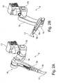
Ferner umfasst die Erfindung einen neuartigen Lackierroboter mit einer Roboterbasis, an der mindestens zwei Roboterarme oder sonstige Roboterglieder beweglich angelenkt sind. In einer Variante der Erfindung führen die beiden Roboterarme jeweils einen Zerstäuber. In einer anderen Variante der Erfindung ist dagegen vorgesehen, dass der eine Roboterarm einen Zerstäuber führt, während der andere Roboterarm ein Handhabungswerkzeug führt, insbesondere einen Greifer zum Öffnen oder Schließen einer Haube oder einer Tür einer Kraftfahrzeugkarosserie.Furthermore, the invention comprises a novel painting robot with a robot base, on which at least two robot arms or other robot members are articulated movably. In a variant of the invention, the two robot arms each carry an atomizer. In another variant of the invention, on the other hand, it is provided that one robot arm guides an atomizer, while the other robot arm guides a handling tool, in particular a gripper for opening or closing a hood or door of a vehicle body.
Darüber hinaus umfasst die Erfindung auch ein Verfahren zum Herstellen, Testen und/oder Montieren einer erfindungsgemäßen Lackierreinrichtung, wobei sich das erfindungsgemäße Verfahren dadurch auszeichnet, dass der Steuerschrank bei der Herstellung mechanisch verstärkt wird, so dass er den Lackierroboter mechanisch abstützen kann.In addition, the invention also includes a method for producing, testing and / or assembling a painting device according to the invention, wherein the method according to the invention is characterized in that the control cabinet is mechanically reinforced during manufacture, so that it can mechanically support the painting robot.
Weiterhin zeichnet sich das erfindungsgemäße Herstellungsverfahren dadurch aus, dass der Lackierroboter an dem als Tragsäule ausgebildeten Steuerschrank unmittelbar oder mittels einer Verfahrschiene oder eines Befestigungsadapters befestigt wird.Furthermore, the manufacturing method according to the invention is characterized in that the painting robot is fastened to the control cabinet designed as a support column directly or by means of a Verfahrschiene or a mounting adapter.
Im Rahmen des erfindungsgemäßen Verfahrens erfolgt vorzugsweise zunächst eine Vormontage eines Moduls, das den Lackierroboter, den Steuerschrank, die Robotersteuerung und/oder die Verfahrschiene umfasst, wobei die Vormontage herstellerseitig erfolgt und nicht kundenseitig.In the context of the method according to the invention, preferably a pre-assembly of a module, which comprises the painting robot, the control cabinet, the robot control and / or the positioning rail, preferably takes place on the manufacturer side and not on the customer side.
Diese Vormontage des Moduls ermöglicht vorzugsweise ein Testen des vormontierten Moduls, wobei das Testen ebenfalls herstellerseitig erfolgt. Im Rahmen dieser Tests kann zum einen die fluidische Funktionsweise des Zerstäubers getestet werden. Es kann also getestet werden, ob der Zerstäuber ordnungsgemäß arbeitet. Darüber hinaus können die Tests an dem vormontierten Modul auch die ordnungsgemäße Bewegungsfähigkeit des Lackierroboters umfassen. Ferner kann im Rahmen der Testarbeiten an dem vormontierten Modul überprüft werden, ob die elektrostatische Beschichtungsmittelaufladung ordnungsgemäß funktioniert. Schließlich besteht noch die Möglichkeit, dass im Rahmen der Testarbeiten an dem vormontierten Modul getestet wird, ob der Lackierroboter an seiner Verfahrschiene ordnungsgemäß verfahren werden kann.This pre-assembly of the module preferably allows testing of the preassembled module, the testing also being made by the manufacturer. As part of these tests, on the one hand, the fluidic functioning of the atomizer can be tested. So it can be tested if the atomizer is working properly. In addition, the tests on the preassembled module may also include the proper mobility of the painting robot. Further, as part of the test work on the preassembled module, it can be checked whether the electrostatic coating agent charging is functioning properly. Finally, there is still the possibility that as part of the test work on the pre-assembled module It is tested whether the painting robot can be moved properly on its travel rail.
Das erfindungsgemäße Verfahren umfasst dann vorzugsweise auch den Transport des vormontierten Moduls zu einem Montageort beim Kunden.The method according to the invention then preferably also comprises the transport of the preassembled module to a mounting location at the customer.
Darüber hinaus umfasst das erfindungsgemäße Verfahren dann vorzugsweise noch die Endmontage des vormontierten und/oder getesteten Moduls an dem Montageort, wobei das Modul dann mechanisch verankert und an sämtliche Leitungen angeschlossen wird, die zum Betrieb des Lackierroboters und des zugehörigen Zerstäubers erforderlich sind. Weitere Testarbeiten sind dann jedoch in der Regel nicht erforderlich, wodurch die Endmontagezeit wesentlich herabgesetzt wird.In addition, the method according to the invention then preferably also comprises the final assembly of the preassembled and / or tested module at the installation site, wherein the module is then mechanically anchored and connected to all lines which are required for operation of the painting robot and the associated atomizer. However, further test work is then usually not required, whereby the final assembly time is significantly reduced.
Es wurde bereits vorstehend erwähnt, dass sich der erfindungsgemäße Lackierroboter aufgrund seiner konstruktiven Gestaltung ("Ellbow down") gut zur Innenlackierung von Kraftfahrzeugkarosserien eignet. Das erfindungsgemäße Verfahren umfasst deshalb auch die Innenlackierung von Kraftfahrzeugkarosserien, wobei der Lackierroboter so positioniert wird, dass das Ellbogengelenk zwischen dem proximalen Roboterarm und dem distalen Roboterarm nach unten gerichtet ist. Der distale Roboterarm mit dem Zerstäuber wird dann so positioniert, dass sich der distale Roboterarm seitlich neben der zu lackierenden Kraftfahrzeugkarosserie im Wesentlichen rechtwinklig zu der Förderrichtung der zu lackierenden Bauteile befindet. Der distale Roboterarm mit dem Zerstäuber ist dann im Wesentlichen horizontal ausgerichtet und wird in horizontaler Richtung in den Innenraum der zu lackierenden Kraftfahrzeugkarosserie eingeführt, um dort den Innenraum zu lackieren.It has already been mentioned above that the painting robot according to the invention, due to its structural design ("elbow-down"), is well suited for the interior painting of motor vehicle bodies. Therefore, the inventive method also includes the interior painting of motor vehicle bodies, wherein the painting robot is positioned so that the elbow joint between the proximal robot arm and the distal robot arm is directed downward. The distal robot arm with the atomizer is then positioned so that the distal robot arm is laterally adjacent to the vehicle body to be painted substantially perpendicular to the conveying direction of the components to be painted. The distal robot arm with the atomizer is then aligned substantially horizontally and is introduced in the horizontal direction in the interior of the vehicle body to be painted, there to paint the interior.
Andere vorteilhafte Weiterbildungen der Erfindung sind in den Unteransprüchen gekennzeichnet oder werden nachstehend zusammen mit der Beschreibung der bevorzugten Ausführungsbeispiele der Erfindung anhand der Figuren näher erläutert. Es zeigen:
- Figur 1
- eine Perspektivansicht einer Lackierkabine mit zwei ortsfest montierten Lackierrobotern,
- Figuren 2A-2F
- verschiedene Perspektivansichten der Lackierroboter aus
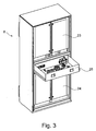
Figur 1 , Figur 3- eine Perspektivansicht eines als Tragsäule ausgebildeten Steuerschranks aus der Lackierkabine gemäß
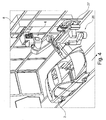
Figur 1 , Figur 4- eine Perspektivansicht einer Lackierkabine mit einem ortsfest montierten Lackierroboter und einem Türöffner, der an einer Stummelschiene unterhalb des Lackierroboters verfahrbar ist,
Figur 5- eine Aufsicht auf die
Lackierkabine aus Figur 4 , Figur 6- eine Perspektivansicht der Lackierkabine aus
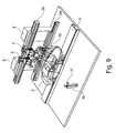
den Figuren 4 und5 , Figur 7- eine Perspektivansicht einer Lackierkabine mit einer Verfahrschiene, an der zwei Lackierroboter verfahrbar sind, wobei auch zwei Handhabungsroboter an der Verfahrschiene verfahrbar sind,
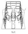
Figur 8- eine Frontansicht einer erfindungsgemäßen Lackierkabine mit verfahrbaren Lackierrobotern und ebenfalls verfahrbaren Handhabungsrobotern,
Figur 9- eine Perspektivansicht einer Lackierkabine mit zwei Verfahrschienen für jeweils zwei Lackierroboter und zwei Handhabungsroboter,
Figur 10- eine Perspektivansicht von zwei Lackierrobotern, die alternativ als Handhabungsroboter einsetzbar sind,
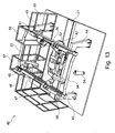
Figur 11- eine Perspektivansicht einer Lackierkabine mit zwei ortsfest montierten Lackierrobotern,
Figur 12- eine Perspektivansicht eines verfahrbaren Lackierroboters, wobei der Lackierroboter an einer verfahrbaren Tragsäule montiert ist, die den Steuerschrank bildet,
Figur 13- eine Perspektivansicht einer erfindungsgemäßen Lackierkabine mit zwei rechtwinklig zur Förderrichtung der Kraftfahrzeugkarosserie verlaufenden Verfahrschienen für jeweils zwei Lackierroboter,
Figur 14- eine Aufsicht auf die
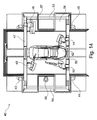
Lackierkabine aus Figur 13 , Figur 15- eine Perspektivansicht der Lackierkabine aus
den Figuren 13 und14 parallel zur Förderrichtung der Kraftfahrzeugkarosserien, Figur 16- eine Perspektivansicht eines alternativen Ausführungsbeispiels einer erfindungsgemäßen Lackierkabine mit einer oben liegenden Verfahrschiene, wobei der Lackierroboter an der Verfahrschiene verfahrbar und gegenüber der Verfahrschiene heruntergesetzt ist,
Figur 17- eine Perspektivansicht der Lackierkabine aus
Figur 17 parallel zur Förderrichtung der Kraftfahrzeugkarosserien, Figur 18- ein erfindungsgemäßes Ausführungsbeispiel eines Lackierroboters mit einer Roboterbasis, an der mehrere Roboterarme beweglich angelenkt sind, sowie
Figur 19- eine Perspektivansicht eines alternativen Ausführungsbeispiels eines Lackierroboters mit mehreren kinematisch parallel angeordneten Roboterarmen.
- FIG. 1
- a perspective view of a paint booth with two stationary mounted paint robots,
- Figures 2A-2F
- different perspective views of the painting robots
FIG. 1 . - FIG. 3
- a perspective view of a designed as a support column control cabinet from the spray booth according to
FIG. 1 . - FIG. 4
- a perspective view of a spray booth with a stationary mounted painting robot and a door opener, which is movable on a stub rail below the painting robot,
- FIG. 5
- a view of the spray booth
FIG. 4 . - FIG. 6
- a perspective view of the paint booth from the
FIGS. 4 and5 . - FIG. 7
- a perspective view of a paint booth with a travel rail on which two painting robots are movable, whereby two handling robots are movable on the travel rail,
- FIG. 8
- a front view of a paint booth according to the invention with movable painting robots and also movable handling robots,
- FIG. 9
- a perspective view of a paint booth with two traversing rails for two painting robots and two handling robots,
- FIG. 10
- a perspective view of two painting robots, which are alternatively usable as a handling robot,
- FIG. 11
- a perspective view of a paint booth with two stationary mounted paint robots,
- FIG. 12
- a perspective view of a movable painting robot, wherein the painting robot is mounted on a movable support column, which forms the control cabinet,
- FIG. 13
- a perspective view of a paint booth according to the invention with two perpendicular to the conveying direction of the motor vehicle body running rails for two painting robots,
- FIG. 14
- a view of the spray booth
FIG. 13 . - FIG. 15
- a perspective view of the paint booth from the
Figures 13 and14 parallel to the conveying direction of the motor vehicle bodies, - FIG. 16
- a perspective view of an alternative embodiment of a paint booth according to the invention with an overhead rail, wherein the painting robot on the travel rail is moved and lowered relative to the travel rail,
- FIG. 17
- a perspective view of the spray booth
FIG. 17 parallel to the conveying direction of the motor vehicle bodies, - FIG. 18
- an inventive embodiment of a painting robot with a robot base on which a plurality of robot arms are articulated movable, and
- FIG. 19
- a perspective view of an alternative embodiment of a painting robot with a plurality of kinematically arranged in parallel robot arms.
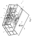
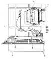
Die Perspektivansicht in
In Förderrichtung vor und hinter der Lackierkabine 1 können weitere Lackierkabinen angeordnet sein, um andere Beschichtungsmittel auf die Kraftfahrzeugkarosserien 2 aufzutragen. Beispielsweise kann in der Lackierkabine 1 eine Basislackschicht auf die Kraftfahrzeugkarosserien 2 aufgetragen werden. In der vorangegangenen Lackierkabine (nicht dargestellt) wird dann zuvor eine Grundierung ("Primer") auf die Kraftfahrzeugkarosserien 2 aufgetragen. In einer in Förderrichtung folgenden Lackierkabine (nicht dargestellt) wird dann eine Klarlackschicht auf die Kraftfahrzeugkarosserien 2 aufgetragen.In the conveying direction in front of and behind the painting booth 1 further painting booths can be arranged to apply other coating agents to the
Die Lackierkabine 1 weist über den gesamten Umfang umlaufend glattflächige Kabinenwände 4, 5 auf, wobei die Kabinenwände teilweise nicht dargestellt sind, um den Einblick in das Innere der Lackierkabine 1 zu ermöglichen. Vorteilhaft an den glattflächigen Kabinenwänden 4, 5 ist die geringe Verschmutzungsanfälligkeit und die gute Reinigungsfähigkeit.The paint booth 1 has over the entire circumference circumferentially smooth-surfaced
Weiterhin ist zu erwähnen, dass die Kabinenwände 4, 5 weitgehend durchsichtig sind, was eine Sichtkontrolle des im Inneren der Lackierkabine 1 ablaufenden Lackierbetriebs durch eine außerhalb der Lackierkabine 1 befindliche Person ermöglicht.Furthermore, it should be mentioned that the
In der Lackierkabine sind zwei mehrachsige Lackierroboter 6, 7 jeweils ortsfest an einem als Tragsäule ausgebildeten Steuerschrank 8, 9 montiert.In the paint booth, two
Die beiden Steuerschränke 8, 9 befinden sich hierbei außerhalb der Lackierkabine 1 und enthalten eine Robotersteuerung zur Ansteuerung der Lackierroboter 6, 7. Die Robotersteuerung in den Steuerschränken 8, 9 kann deshalb gewartet werden, ohne dass das Wartungspersonal die Lackierkabine 1 betreten muss.The two
Die Steuerschränke 8, 9 sind hierbei gegenüber herkömmlichen Steuerschränken mechanisch massiv verstärkt, um neben der Beherbergung der Robotersteuerung auch eine mechanische Tragfunktion für die Lackierroboter 6, 7 erfüllen zu können.The
Die beiden Lackierroboter 6, 7 bilden hierbei zusammen mit den zugehörigen Steuerschränken 8, 9 und der darin befindlichen Robotersteuerung ein vormontiertes Modul, das von dem Hersteller der Lackierroboter vormontiert und getestet geliefert wird, so dass diese Module bei der Endmontage beim Kunden einfach aufgestellt werden können. Bei der Endmontage ist also nur noch eine mechanische Fixierung der Steuerschränke 8, 9 erforderlich sowie ein Anschluss der Steuerschränke 8, 9 an die zum Betrieb erforderlichen Leitungen (z.B. für Druckluft, Lacke, Spülmittel, Strom, etc.).The two
Die in den Steuerschränken 8, 9 befindlichen Robotersteuerungen können von einer außerhalb der Lackierkabine 1 befindlichen Bedienungsperson 10 mittels eines tragbaren Programmiergeräts 11 programmiert werden, wobei das Programmiergerät 11 eine drahtlose Datenübertragung von und zu den Robotersteuerungen ermöglicht.The robot controls located in the
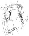
Die
So bestehen die Lackierroboter 6, 7 im Wesentlichen aus einer Roboterbasis 12, einem drehbaren Roboterteil 13, einem proximalen Roboterarm 14, einem distalen Roboterarm 15, einer Roboterhandachse 16 und einem Rotationszerstäuber 17.Thus, the
Das drehbare Roboterteil 13 ist hierbei unterhalb der Roboterbasis 12 angeordnet und relativ zu der Roboterbasis 12 um eine senkrechte Drehachse drehbar.The
Der proximale Roboterarm 14 ist dagegen relativ zu dem drehbaren Roboterteil 13 um eine horizontale Schwenkachse schwenkbar.By contrast, the
Das Gleiche gilt sinngemäß für den distalen Roboterarm 15, der um eine horizontal verlaufende Schwenkachse relativ zu dem proximalen Roboterarm 14 schwenkbar ist.The same applies mutatis mutandis to the
Weiterhin ist zu erwähnen, dass der proximale Roboterarm 14 durch ein Ellbogengelenk 18 mit dem distalen Roboterarm 15 verbunden ist. In der in
Aus
Weiterhin ist aus
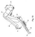
Aus der Perspektivansicht in
Die
Zum Einen ist hierbei zu erwähnen, dass die Versorgungsschläuche 21 zwischen dem drehbaren Roboterteil und dem distalen Roboterarm 15 jeweils in einer Schlauchebene verlaufen, die rechtwinklig zur Schwenkachse der Roboterarme 14, 15 ausgerichtet ist. Dies bedeutet, dass die Versorgungsschläuche 21 bei einem Schwenken der Roboterarme 14, 15 nur auf Biegung in der Schlauchebene beansprucht werden, d.h. nur in einer Richtung.On the one hand, it should be mentioned here that the
Zum anderen ist zu erwähnen, dass der proximale Roboterarm 14 um eine Schwenkachse 22 relativ zu dem drehbaren Roboterteil 13 schwenkbar ist, wobei die Versorgungsschläuche 21 in dem Gelenk zwischen dem proximalen Roboterarm 14 und dem drehbaren Roboterteil 13 durch die Schwenkachse 22 geführt sind. Dies bietet den Vorteil, dass die Versorgungsschläuche 21 bei einer Schwenkbewegung des proximalen Roboterarms 14 nur relativ geringfügigen mechanischen Belastungen unterworfen sind.On the other hand, it should be mentioned that the
Aus dem gleichen Grund sind die Versorgungsschläuche 21 in den Gelenken jeweils in der sogenannten neutralen Faser geführt, in der lediglich Biegebelastungen der Versorgungsschläuche 21 auftreten, aber keine axialen Zug- oder Druckkräfte.For the same reason, the
Der Steuerschrank 8 weist im oberen Bereich und im unteren Bereich jeweils Platz für eine Robotersteuerung 23, 24 auf.The
Darüber hinaus weist der Steuerschrank 8 in der Mitte eine Schublade 25 auf, in der beispielsweise Ersatzteile, Betriebsanleitungen oder auch herrenlose Putzlappen untergebracht werden können.In addition, the
Die
Eine Besonderheit dieses Ausführungsbeispiels besteht darin, dass zusätzlich zu dem Lackierroboter 6 ein Handhabungsroboter 26 vorgesehen ist, der die Aufgabe hat, die Türen der Kraftfahrzeugkarosserien 2 für eine anschließende Innenlackierung durch den Lackierroboter 6 zu öffnen.A special feature of this embodiment is that in addition to the
Der Handhabungsroboter 26 ist unterhalb des Lackierroboters 6 an einer Stummelschiene 27 montiert und in Pfeilrichtung verfahrbar.The handling
Die Stummelschiene 27 des Handhabungsroboters 26 ist hierbei gegenüber dem Lackierroboter 6 in Förderrichtung versetzt angeordnet. Dies ist vorteilhaft, damit der Handhabungsroboter 26 nach dem Abschluss der Innenlackierung durch den Lackierroboter 6 noch genügend Zeit hat, um die Tür der Kraftfahrzeugkarosserie 2 zu schließen, bevor die Kraftfahrzeugkarosserie 2 die Reichweite des Handhabungsroboters 26 in Pfeilrichtung verlässt.The
Der Vollständigkeit halber ist darauf hinzuweisen, dass die vorstehend erwähnten Lackiereinrichtungen in der Lackierkabine auf beiden Seiten der Kraftfahrzeugkarosserie 2 symmetrisch angeordnet sind.For the sake of completeness, it should be pointed out that the above-mentioned painting devices are arranged symmetrically in the paint booth on both sides of the
Die
Eine Besonderheit dieses Ausführungsbeispiels besteht darin, dass die Lackierroboter 6, 7 in diesem Ausführungsbeispiel nicht ortsfest montiert sind, sondern an einer gemeinsamen Verfahrschiene 28.A special feature of this embodiment is that the
Darüber hinaus sind auch die Handhabungsroboter 26 in diesem Ausführungsbeispiel an der Verfahrschiene 28 aufgehängt.In addition, the handling
Eine Besonderheit dieses Ausführungsbeispiels besteht darin, dass an den als Tragsäule ausgebildeten Steuerschränken 8, 9 im unteren Bereich eine weitere Verfahrschiene 29 montiert ist. Die Verfahrschiene 29 trägt hierbei die Handhabungsroboter 26, wohingegen die obere Verfahrschiene 28 die Lackierroboter 6, 7 trägt.A special feature of this embodiment is that a
Schließlich zeigt
Eine Besonderheit dieses Ausführungsbeispiels besteht darin, dass die Drehachse zwischen der Roboterbasis 12 und dem drehbaren Roboterteil 13 waagerecht ausgerichtet ist und parallel zur Transportrichtung der Fördereinrichtung 3 verläuft.A special feature of this embodiment is that the axis of rotation between the
Die Schwenkachsen des proximalen Roboterarms 14 und des distalen Roboterarms verlaufen dagegen hierbei in einer Ebene, die rechtwinklig zu der Transportrichtung der Fördereinrichtung 3 ausgerichtet ist.The pivot axes of the
Der Lackierroboter 32 ist an einer Tragsäule 37 in vertikaler Richtung (Z-Richtung) verfahrbar. Eine Besonderheit besteht hierbei darin, dass die Tragsäule 37 nicht nur zur mechanischen Führung des Lackierroboters 32 dient, sondern auch eine Robotersteuerung und/oder Applikationstechnik für den Lackierroboter 32 enthält, wobei die Pneumatik für den Lackierroboter 32 in die Tragsäule 37 integriert sein kann. Die Tragsäule 37 bildet also in diesem Ausführungsbeispiel einen Steuerschrank für den Lackierroboter.The
Die Tragsäule 37 ist an zwei übereinander liegenden, parallelen Verfahrschienen 38, 39 in X-Richtung verfahrbar, d.h. in Förderrichtung der zu lackierenden Kraftfahrzeugkarosserien.The
Die
Durch die Lackierkabine 40 verläuft hierbei ein Förderer 41 entlang dem Kraftfahrzeugkarosserien 42 linear durch die Lackierkabine 40 transportiert werden, was an sich aus dem Stand der Technik bekannt ist und deshalb nicht näher beschrieben werden muss.Through the
Außerhalb der Lackierkabine befinden sich hierbei vier Tragsäulen 43, 44, 45, 46, wobei die eingangsseitig angeordneten Tragsäulen 43, 46 eine eingangsseitig angeordnete Verfahrschiene 47 tragen, die rechtwinklig zur Förderrichtung des Förderers 41 ausgerichtet ist. Entlang der Verfahrschiene 47 sind zwei Lackierroboter 48, 49 rechtwinklig zur Förderrichtung des Förderers 41 verfahrbar.Outside the spray booth here are four
Die beiden ausgangsseitig angeordneten Tragsäulen 44, 45 tragen an ihrer Oberseite gemeinsam eine weitere Verfahrschiene 50, die ebenfalls rechtwinklig zu Förderrichtung des Förderers 41 ausgerichtet ist. An der Verfahrschiene 50 sind ebenfalls zwei Lackierroboter 51, 52 verfahrbar angeordnet.The two output side arranged
Die Lackierroboter 48, 49 und 51, 52 weisen hierbei jeweils eine sogenannte inverse Kinematik auf. Dies bedeutet, dass die Roboterbasis der Lackierroboter 48, 49, 51, 52 gegenüber herkömmlichen Lackierrobotern umgedreht ist, so dass sich die Roboterarme der Lackierroboter 48, 49, 51, 52 unterhalb der jeweiligen Roboterbasis befindet.The
Die beiden Verfahrschienen 47, 50 sind jeweils an ihren Enden durch eine Längsstrebe 53, 54 miteinander verbunden, so dass die beiden Verfahrschienen 47, 50 zusammen mit den Längsstreben 53, 54 einen stabilen Rahmen bilden.The two
Die Lackierkabine 40 wird seitlich und an ihren Stirnseiten durch eine umlaufende Kabinenwand 55 begrenzt, wobei die Kabinenwand 55 durchsichtig ist, so dass eine außerhalb der Lackierkabine 40 befindliche Bedienungsperson 56 von außen eine Sichtkontrolle des innerhalb der Lackierkabine 40 stattfindenden Lackierprozesses durchführen kann.The
Weiterhin ist zu erwähnen, dass die Kabinenwand 55 seitlich in der Verlängerung der beiden Verfahrschienen 47, 50 jeweils eine seitliche Ausbuchtung 57, 58 aufweist, so dass die Lackierroboter 48, 49 bzw. 51, 52 auf den Verfahrschienen 47, 50 in seitlicher Richtung bis in die Ausbuchtungen 57, 58 hineingefahren werden können, wodurch der Bewegungsspielraum der Lackierroboter 48, 49, 51, 52 in seitlicher Richtung erweitert wird. Zwischen den seitlichen Ausbuchtungen 57, 58 ist die Kabinenbreite der Lackierkabine 40 dagegen geringer als im Bereich der Ausbuchtungen 57, 58, so dass die Bedienungsperson 56 den im Inneren der Lackierkabine ablaufenden Lackierprozess aus geringer Entfernung beobachten kann, wie insbesondere aus
Das Ausführungsbeispiel gemäß den
Eine Besonderheit dieses Ausführungsbeispiels besteht darin, dass der Lackierroboter 6 gegenüber der Verfahrschiene 28 nach unten versetzt angeordnet ist, obwohl der Lackierroboter 6 auf der oberen Verfahrschiene 28 verfahrbar ist. Hierzu dient ein im Wesentlichen vertikal ausgerichteter Träger 59, der an seiner Oberseite an der Verfahrschiene 28 verfahrbar ist, während der Träger 59 an seiner Unterseite die Roboterbasis des Lackierroboters 6 trägt. Der Träger 59 dient also dazu, den Lackierroboter 6 gegenüber der oberen Verfahrschiene 28 herunterzusetzen.A special feature of this embodiment is that the
An der Roboterbasis 60 sind auf gegenüberliegenden Seiten zwei Roboterteile 61, 62 drehbar gelagert, wobei die beiden Roboterteile 61, 62 relativ zu der gemeinsamen Roboterbasis 60 um eine gemeinsame, horizontal verlaufende Drehachse drehbar sind.On the
An dem drehbaren Roboterteil 61 sind ein proximaler Roboterarm 63 und ein distaler Roboterarm 64 schwenkbar angeordnet, wobei der distale Roboterarm 64 über eine Roboterhandachse 65 einen Rotationszerstäuber 66 führt.On the
In gleicher Weise sind an dem drehbaren Roboterteil 62 ein proximaler Roboterarm 67 und ein distaler Roboterarm 68 schwenkbar angeordnet, wobei der distale Roboterarm 68 über eine Roboterhandachse 69 ebenfalls einen Rotationszerstäuber 70 führt.Likewise, a proximal
Weiterhin ist zu erwähnen, dass auf dem distalen Roboterarm 68 Applikationstechnik 70 angeordnet ist, was in gleicher Weise auch für den geschlossen dargestellten distalen Roboterarm 64 gilt.It should also be mentioned that
Eine Besonderheit dieses Ausführungsbeispiels besteht darin, dass der distale Roboterarm 68 keinen Rotationszerstäuber führt, sondern einen Griff 72 zum Öffnen bzw. Schließen einer Haube einer Kraftfahrzeugkarosserie. Der Lackierroboter ermöglicht also in diesem Ausführungsbeispiel nicht nur die Applikation von Lack, sondern dient auch als Handhabungsroboter und konkret als Haubenöffner.A special feature of this embodiment is that the
Weiterhin ist zu diesem Ausführungsbeispiel zu erwähnen, dass der proximale Roboterarm 67 ohne Zwischenschaltung des Roboterteils 62 direkt an der Roboterbasis 60 schwenkbar angelenkt ist.Furthermore, it should be mentioned in this embodiment that the
Die Erfindung ist nicht auf die vorstehend beschriebenen bevorzugten Ausführungsbeispiele beschränkt. Vielmehr ist eine Vielzahl von Varianten und Abwandlungen möglich, die ebenfalls von dem Erfindungsgedanken Gebrauch machen und deshalb in den Schutzbereich fallen.The invention is not limited to the preferred embodiments described above. Rather, a variety of variants and modifications is possible, which also make use of the inventive idea and therefore fall within the scope.
Weiterhin ist zu bemerken, dass die Erfindung auch Schutz beansprucht für den Gegenstand der beiliegenden Unteransprüche ohne die Merkmale der übergeordneten und in Bezug genommenen Ansprüche oder nur mit einigen Merkmalen der übergeordneten Ansprüche.
Claims (23)
dadurch gekennzeichnet,
characterized,
dadurch gekennzeichnet,
characterized,
dadurch gekennzeichnet,
characterized,
dadurch gekennzeichnet,
characterized,
gekennzeichnet durch
marked by
oder
or
Priority Applications (1)
| Application Number | Priority Date | Filing Date | Title |
|---|---|---|---|
| PL13005361T PL2698232T3 (en) | 2008-09-03 | 2009-08-19 | Painting device |
Applications Claiming Priority (2)
| Application Number | Priority Date | Filing Date | Title |
|---|---|---|---|
| DE102008045553A DE102008045553A1 (en) | 2008-09-03 | 2008-09-03 | Painting device and associated method |
| EP09777972.2A EP2318185B1 (en) | 2008-09-03 | 2009-08-19 | Painting device |
Related Parent Applications (1)
| Application Number | Title | Priority Date | Filing Date |
|---|---|---|---|
| EP09777972.2A Division EP2318185B1 (en) | 2008-09-03 | 2009-08-19 | Painting device |
Publications (3)
| Publication Number | Publication Date |
|---|---|
| EP2698232A2 true EP2698232A2 (en) | 2014-02-19 |
| EP2698232A3 EP2698232A3 (en) | 2014-03-12 |
| EP2698232B1 EP2698232B1 (en) | 2015-04-22 |
Family
ID=41136766
Family Applications (2)
| Application Number | Title | Priority Date | Filing Date |
|---|---|---|---|
| EP20130005361 Active EP2698232B1 (en) | 2008-09-03 | 2009-08-19 | Painting device |
| EP09777972.2A Revoked EP2318185B1 (en) | 2008-09-03 | 2009-08-19 | Painting device |
Family Applications After (1)
| Application Number | Title | Priority Date | Filing Date |
|---|---|---|---|
| EP09777972.2A Revoked EP2318185B1 (en) | 2008-09-03 | 2009-08-19 | Painting device |
Country Status (8)
| Country | Link |
|---|---|
| US (2) | US8627780B2 (en) |
| EP (2) | EP2698232B1 (en) |
| JP (2) | JP2012501820A (en) |
| CN (2) | CN107097205B (en) |
| DE (1) | DE102008045553A1 (en) |
| ES (1) | ES2449395T3 (en) |
| PL (2) | PL2318185T3 (en) |
| WO (1) | WO2010025827A1 (en) |
Cited By (1)
| Publication number | Priority date | Publication date | Assignee | Title |
|---|---|---|---|---|
| CN104858088A (en) * | 2015-06-04 | 2015-08-26 | 马鞍山市安工大工业技术研究院有限公司 | Paint spraying robot used for spraying automobile spring |
Families Citing this family (64)
| Publication number | Priority date | Publication date | Assignee | Title |
|---|---|---|---|---|
| DE102008045553A1 (en) * | 2008-09-03 | 2010-03-04 | Dürr Systems GmbH | Painting device and associated method |
| US20100145516A1 (en) * | 2008-12-08 | 2010-06-10 | Illinois Tool Works Inc. | High voltage monitoring system and method for spray coating systems |
| DE102009012140A1 (en) * | 2009-03-06 | 2010-09-09 | Dürr Systems GmbH | Robot arrangement, in particular in a paint booth |
| EP2497576A4 (en) * | 2009-11-06 | 2013-08-28 | Honda Motor Co Ltd | Coating system |
| DE102010018468A1 (en) | 2010-04-27 | 2011-10-27 | Dürr Systems GmbH | Device and method for handling preferably to be coated components |
| DE102010023578B4 (en) * | 2010-06-12 | 2018-02-22 | Abb Ag | Painting plant for coating / painting an elongated workpiece |
| JP2012121105A (en) * | 2010-12-09 | 2012-06-28 | Yaskawa Electric Corp | Painting robot and painting system |
| DE102011017347A1 (en) | 2011-04-16 | 2012-10-18 | Eisenmann Ag | Treatment unit, installation and process for the surface treatment of objects |
| JP5418545B2 (en) * | 2011-06-24 | 2014-02-19 | 株式会社安川電機 | Painting system |
| DE102011108262B4 (en) * | 2011-07-25 | 2015-12-17 | Eisenmann Ag | Apparatus for painting vehicle bodies with a plurality of gestaltveranderlichen arms |
| JP5585553B2 (en) * | 2011-08-01 | 2014-09-10 | 株式会社安川電機 | Opening and closing hand of painting system and door opening and closing robot |
| CN102921581B (en) * | 2011-08-09 | 2015-07-22 | 株式会社安川电机 | Coating system and door opening-closing hand of door opening-closing robot |
| EP2556929B1 (en) * | 2011-08-10 | 2015-02-18 | Kabushiki Kaisha Yaskawa Denki | Painting system |
| DE102011121343A1 (en) | 2011-12-16 | 2013-06-20 | Dürr Systems GmbH | Coating plant and corresponding operating method |
| CN102728508A (en) * | 2012-07-17 | 2012-10-17 | 昆山华恒焊接股份有限公司 | Robot coating system |
| CN103769332B (en) * | 2012-09-10 | 2017-12-01 | 发纳科机器人美国公司 | Redundant robot and robotic painting system |
| DE102013013038A1 (en) * | 2013-08-05 | 2015-02-05 | Dürr Systems GmbH | Coating robot and corresponding coating method |
| USD755867S1 (en) * | 2013-10-07 | 2016-05-10 | Jorge Juan Garcia Garcia | Telescopic articulated arm |
| US9759089B2 (en) * | 2013-12-10 | 2017-09-12 | General Electric Company | Transportable modular coating systems and methods |
| DE102014000478A1 (en) * | 2014-01-16 | 2015-07-16 | Dürr Systems GmbH | Shield device for a travel rail |
| US9861998B2 (en) * | 2014-04-07 | 2018-01-09 | Oria Collapsibles, Llc | Assembly for coating an article incorporating robotic subassemblies utilizing articulating spray arms and carousel conveyor with inlet and outlet locations for the article |
| DE102014207275A1 (en) * | 2014-04-15 | 2015-10-15 | Kuka Systems Gmbh | Robotic device with a linear axis |
| DE102014006651A1 (en) | 2014-05-07 | 2015-11-12 | Dürr Systems GmbH | Coating system for coating components, in particular for painting motor vehicle body components |
| US9339833B2 (en) * | 2014-05-08 | 2016-05-17 | Ford Motor Company | Compact fluid delivery system for automation |
| BR112017001892B1 (en) * | 2014-07-31 | 2021-03-02 | Geico S.P.A. | station and installation to treat objects |
| KR101702716B1 (en) * | 2014-10-28 | 2017-02-13 | 김재호 | Pipe swivel pipe painting painting method and a device, the device |
| JP6567819B2 (en) * | 2014-12-09 | 2019-08-28 | 川崎重工業株式会社 | Automatic production system |
| DE102015003136A1 (en) * | 2015-03-11 | 2016-09-15 | Kuka Roboter Gmbh | robot storage |
| JP6068548B2 (en) * | 2015-04-09 | 2017-01-25 | ファナック株式会社 | An articulated robot in which connecting members for connecting the striatum are arranged on the arm |
| CN104972589B (en) * | 2015-06-24 | 2017-07-14 | 东莞市松庆智能自动化科技有限公司 | A kind of multi-shaft interlocked formula robot and its automatic casting system |
| WO2017029711A1 (en) * | 2015-08-18 | 2017-02-23 | 株式会社安川電機 | Painting system and painting method |
| DE102015015089A1 (en) * | 2015-11-20 | 2017-05-24 | Dürr Systems Ag | Pressurized enclosure system for explosion protection and corresponding operating procedure |
| DE102016001073B4 (en) * | 2016-02-02 | 2018-10-25 | Eisenmann Se | Multi-axis robot and method for its control in the painting of objects |
| DE102016003966A1 (en) * | 2016-04-01 | 2017-10-05 | Dürr Systems Ag | coating robot |
| DE102016004846A1 (en) * | 2016-04-22 | 2017-10-26 | Dürr Systems Ag | varnishing |
| DE102016014952A1 (en) | 2016-12-14 | 2018-06-14 | Dürr Systems Ag | Coating device for coating components |
| DE102016014955A1 (en) | 2016-12-14 | 2018-06-14 | Dürr Systems Ag | Coating device and corresponding coating method |
| DE102016014919A1 (en) | 2016-12-14 | 2018-06-14 | Dürr Systems Ag | Application device and method for applying a coating agent |
| DE102016014944A1 (en) | 2016-12-14 | 2018-06-14 | Dürr Systems Ag | Coating method and corresponding coating device |
| DE102016014948A1 (en) | 2016-12-14 | 2018-06-14 | Dürr Systems Ag | Printhead and related operating procedures |
| DE102016014951A1 (en) | 2016-12-14 | 2018-06-14 | Dürr Systems Ag | Coating device and associated operating method |
| DE102016014953A1 (en) * | 2016-12-14 | 2018-06-14 | Dürr Systems Ag | Painting plant and corresponding painting process |
| DE102016014947A1 (en) | 2016-12-14 | 2018-06-14 | Dürr Systems Ag | Printhead for applying a coating agent |
| DE102016014956A1 (en) | 2016-12-14 | 2018-06-14 | Dürr Systems Ag | Coating device and associated operating method |
| DE102016014943A1 (en) | 2016-12-14 | 2018-06-14 | Dürr Systems Ag | Printhead with tempering device |
| DE102016014946A1 (en) | 2016-12-14 | 2018-06-14 | Dürr Systems Ag | Printhead for applying a coating agent to a component |
| CN106628906B (en) * | 2016-12-26 | 2019-07-26 | 迈赫机器人自动化股份有限公司 | A kind of robot lift and conveyer |
| CN107471902A (en) * | 2017-08-17 | 2017-12-15 | 重庆凌慧科技有限公司 | A kind of Automatic-feeding pen |
| JP6900862B2 (en) * | 2017-09-22 | 2021-07-07 | 株式会社デンソーウェーブ | Mobile robot |
| CN107803823B (en) * | 2017-12-01 | 2023-12-12 | 韩山师范学院 | Automatic assembly production line with mechanical arm |
| CN108058157A (en) * | 2018-01-29 | 2018-05-22 | 西安优艾智合机器人科技有限公司 | A kind of crusing robot |
| WO2019213616A1 (en) | 2018-05-03 | 2019-11-07 | Fanuc America Corporation | Robotic apparatus for a compact painting booth |
| USD888521S1 (en) * | 2018-06-19 | 2020-06-30 | William E. Howseman, Jr. | Spray gun elevator |
| USD888522S1 (en) * | 2018-06-19 | 2020-06-30 | William E. Howseman, Jr. | Spray gun elevator |
| EP3685925B1 (en) * | 2018-08-14 | 2022-10-26 | pentanova cs GmbH | Method and device for spray painting a workpiece |
| US20200061828A1 (en) * | 2018-08-27 | 2020-02-27 | Ascend Robotics LLC | Automated construction robot systems and methods |
| DE102019119613A1 (en) * | 2019-07-19 | 2021-01-21 | Bayerische Motoren Werke Aktiengesellschaft | Method for painting an outer skin component of a motor vehicle and painting station for an outer skin component of a motor vehicle |
| EP3771522A1 (en) * | 2019-07-30 | 2021-02-03 | Siemens Aktiengesellschaft | Method and manipulation system for manipulating an object by a robot with vector fields |
| CN111561869B (en) * | 2020-05-22 | 2021-11-23 | 延锋彼欧武汉汽车外饰系统有限公司 | Intelligent detection device and method for vehicle body space position and application thereof |
| JP7396220B2 (en) * | 2020-07-06 | 2023-12-12 | トヨタ自動車株式会社 | Painting equipment and how to install it |
| CN111905955B (en) * | 2020-07-08 | 2021-08-06 | 威海英博特精密机械有限公司 | Industrial automation robot that sprays paint |
| TWI768600B (en) * | 2020-12-17 | 2022-06-21 | 魏榮宗 | Exhaust gas purification system |
| CN112657737A (en) * | 2020-12-31 | 2021-04-16 | 深圳元尚实业有限公司 | Movable spraying platform |
| DE102021205536A1 (en) * | 2021-05-31 | 2022-12-01 | Adidas Ag | Process for applying materials to shoes |
Citations (5)
| Publication number | Priority date | Publication date | Assignee | Title |
|---|---|---|---|---|
| DE2915603C2 (en) | 1979-04-18 | 1983-10-27 | Zahnradfabrik Friedrichshafen Ag, 7990 Friedrichshafen | Handling device for load transfer maneuvers that take place perpendicular to the support base and around a swivel axis parallel to it, with the ability to be adjusted transversely |
| DE9212718U1 (en) | 1992-09-22 | 1992-11-26 | Kell, Gerhard, 6074 Roedermark, De | |
| DE69102353T2 (en) | 1990-06-27 | 1994-10-20 | Kobe Steel Ltd | Process for painting cars. |
| DE4430234A1 (en) | 1993-08-25 | 1995-03-02 | Mazda Motor | Method for the detection of crawling in coatings and coating system using the said method |
| DE69629246T2 (en) | 1995-05-31 | 2004-04-15 | Kawasaki Jukogyo K.K., Kobe | Arrangement for the installation of painting robots in a painting line |
Family Cites Families (40)
| Publication number | Priority date | Publication date | Assignee | Title |
|---|---|---|---|---|
| DE10224858B4 (en) * | 2002-06-05 | 2005-07-14 | Kuka Roboter Gmbh | Device for guiding a hose |
| JPS5895558A (en) * | 1981-11-30 | 1983-06-07 | Mazda Motor Corp | Robot for motorcar body coating |
| JPS60860A (en) * | 1983-06-20 | 1985-01-05 | Toyota Motor Corp | Color changing device with robot for painting |
| CA1263015A (en) | 1985-07-31 | 1989-11-21 | Tadashi Takeo | Painting process for inner panel region of motorcar vehicle body and apparatus therefor |
| JPH0247951B2 (en) * | 1985-10-04 | 1990-10-23 | Honda Motor Co Ltd | JIDOSHASHATAINONAIBANBUTOSOHOHO |
| US4630567A (en) * | 1985-08-28 | 1986-12-23 | Gmf Robotics Corporation | Spray paint system including paint booth, paint robot apparatus movable therein and rail mechanism for supporting the apparatus thereout |
| JPH026868A (en) * | 1988-06-25 | 1990-01-11 | Taikisha Ltd | Method for setting coating device in coating booth and coating machine operating unit constituting part of coating booth |
| US5014644A (en) * | 1989-05-23 | 1991-05-14 | Honda Giken Kogyo Kabushiki Kaisha | Apparatus for coating automotive body |
| JPH05200333A (en) * | 1992-01-27 | 1993-08-10 | Toyota Motor Corp | Automatic coating machine |
| JPH05302429A (en) * | 1992-02-26 | 1993-11-16 | Shimizu Corp | Spraying apparatus and spraying execution method |
| FR2710858B1 (en) * | 1993-10-06 | 1995-12-15 | Sames Sa | Coating product projection device forming a roof machine or side machine. |
| JPH07227556A (en) | 1994-02-18 | 1995-08-29 | Mesatsuku:Kk | Coating device for coating robot and its operating method |
| JPH09308848A (en) * | 1996-05-20 | 1997-12-02 | Tokico Ltd | Color changing device and robot for coating |
| JPH10180178A (en) * | 1996-12-27 | 1998-07-07 | Sekisui Chem Co Ltd | Coating method of external wall material for corner |
| FR2777383B1 (en) | 1998-04-09 | 2000-05-12 | Alsthom Cge Alcatel | MULTILAYER CONDUCTOR WITH REDUCED SKIN EFFECT |
| FR2777483A1 (en) * | 1998-04-15 | 1999-10-22 | Sames Sa | METHOD AND INSTALLATION FOR SPRAYING COATING PRODUCTS |
| JP2000167450A (en) * | 1998-11-30 | 2000-06-20 | Tokico Ltd | Robot for coating |
| JP2000167451A (en) * | 1998-12-04 | 2000-06-20 | Toyota Motor Corp | Automobile painting system |
| FR2804349B1 (en) | 2000-01-31 | 2002-07-19 | Eisenmann France Sarl | SPRAYING DEVICE, ESPECIALLY FOR A CAR BODY PAINTING CAB |
| DE10103067A1 (en) | 2001-01-24 | 2002-07-25 | Duerr Systems Gmbh | A method for automatically changing the spray head of a paint spraying robotic machine has the multi-axis nozzle and paint reservoir detachable through a connecting interface |
| US6757586B2 (en) * | 2001-09-05 | 2004-06-29 | Abb Automation Inc. | Multiple arm robot arrangement |
| CA2503485C (en) * | 2002-10-23 | 2013-05-07 | Fanuc Robotics America, Inc. | Modular painting apparatus |
| CA2515683A1 (en) * | 2003-02-21 | 2004-09-02 | Honda Motor Co., Ltd. | Coating system for protective layer forming material |
| JP2004261650A (en) * | 2003-02-21 | 2004-09-24 | Honda Motor Co Ltd | System and method for applying protective layer forming material |
| JP3885036B2 (en) * | 2003-03-14 | 2007-02-21 | 本田技研工業株式会社 | Method and apparatus for applying protective layer forming material |
| GB2417090A (en) * | 2003-04-28 | 2006-02-15 | Stephen James Crampton | CMM arm with exoskeleton |
| DE202004021742U1 (en) * | 2003-07-18 | 2010-09-02 | Abb As | Inking system |
| US8051796B2 (en) * | 2003-10-23 | 2011-11-08 | Fanuc Robotics America, Inc. | Robotic apparatus and method for painting |
| WO2005046880A2 (en) * | 2003-11-06 | 2005-05-26 | Fanuc Robotics America, Inc. | Compact robotic painting booth |
| KR100495707B1 (en) * | 2003-12-09 | 2005-06-17 | 대한도장플랜트(주) | Painting articulated robot possible of setting action range |
| DE102004056493A1 (en) | 2004-06-25 | 2006-01-12 | Dürr Systems GmbH | Paint-spray line for painting motor vehicle body parts, has two linear guides moveable along application and handling robots, where each of two linear guides is provided to guide one of application robots and one of handling robots |
| DE102004040162B4 (en) * | 2004-08-19 | 2013-10-24 | Eisenmann Ag | Device for coating objects |
| DE102005013014A1 (en) * | 2005-03-21 | 2006-10-05 | Dürr Systems GmbH | Coating plant and associated method |
| US7644571B2 (en) * | 2005-06-01 | 2010-01-12 | Durr Systems, Inc. | Hose conduit element for a paint robot |
| FR2890876B1 (en) * | 2005-09-19 | 2007-11-30 | Sames Technologies Soc Par Act | PROJECTION INSTALLATION OF MULTI-COMPONENT COATING PRODUCT |
| DE102006032804A1 (en) | 2006-07-14 | 2008-01-17 | Dürr Systems GmbH | Painting plant and associated operating method |
| KR101452349B1 (en) * | 2006-09-27 | 2014-10-21 | 듀르 시스템스 게엠베하 | Electrostatic sprayer arrangement |
| DE102006058350A1 (en) * | 2006-12-11 | 2008-06-12 | Dürr Systems GmbH | Coating plant and process for serial coating of workpieces |
| DE102007062403A1 (en) * | 2007-12-20 | 2009-06-25 | Abb Ag | Arrangement of painting robots |
| DE102008045553A1 (en) * | 2008-09-03 | 2010-03-04 | Dürr Systems GmbH | Painting device and associated method |
-
2008
- 2008-09-03 DE DE102008045553A patent/DE102008045553A1/en not_active Withdrawn
-
2009
- 2009-08-19 PL PL09777972T patent/PL2318185T3/en unknown
- 2009-08-19 EP EP20130005361 patent/EP2698232B1/en active Active
- 2009-08-19 EP EP09777972.2A patent/EP2318185B1/en not_active Revoked
- 2009-08-19 PL PL13005361T patent/PL2698232T3/en unknown
- 2009-08-19 CN CN201610873232.7A patent/CN107097205B/en active Active
- 2009-08-19 CN CN200980134501.6A patent/CN102177002B/en active Active
- 2009-08-19 JP JP2011525434A patent/JP2012501820A/en active Pending
- 2009-08-19 ES ES09777972.2T patent/ES2449395T3/en active Active
- 2009-08-19 US US13/062,070 patent/US8627780B2/en active Active
- 2009-08-19 WO PCT/EP2009/006007 patent/WO2010025827A1/en active Application Filing
-
2013
- 2013-12-05 US US14/097,567 patent/US9630199B2/en active Active
-
2015
- 2015-05-01 JP JP2015094011A patent/JP6188740B2/en active Active
Patent Citations (5)
| Publication number | Priority date | Publication date | Assignee | Title |
|---|---|---|---|---|
| DE2915603C2 (en) | 1979-04-18 | 1983-10-27 | Zahnradfabrik Friedrichshafen Ag, 7990 Friedrichshafen | Handling device for load transfer maneuvers that take place perpendicular to the support base and around a swivel axis parallel to it, with the ability to be adjusted transversely |
| DE69102353T2 (en) | 1990-06-27 | 1994-10-20 | Kobe Steel Ltd | Process for painting cars. |
| DE9212718U1 (en) | 1992-09-22 | 1992-11-26 | Kell, Gerhard, 6074 Roedermark, De | |
| DE4430234A1 (en) | 1993-08-25 | 1995-03-02 | Mazda Motor | Method for the detection of crawling in coatings and coating system using the said method |
| DE69629246T2 (en) | 1995-05-31 | 2004-04-15 | Kawasaki Jukogyo K.K., Kobe | Arrangement for the installation of painting robots in a painting line |
Cited By (1)
| Publication number | Priority date | Publication date | Assignee | Title |
|---|---|---|---|---|
| CN104858088A (en) * | 2015-06-04 | 2015-08-26 | 马鞍山市安工大工业技术研究院有限公司 | Paint spraying robot used for spraying automobile spring |
Also Published As
| Publication number | Publication date |
|---|---|
| CN107097205B (en) | 2020-06-19 |
| EP2318185B1 (en) | 2013-12-11 |
| US20110166708A1 (en) | 2011-07-07 |
| PL2318185T3 (en) | 2014-05-30 |
| WO2010025827A1 (en) | 2010-03-11 |
| CN102177002A (en) | 2011-09-07 |
| JP2012501820A (en) | 2012-01-26 |
| ES2449395T3 (en) | 2014-03-19 |
| JP6188740B2 (en) | 2017-08-30 |
| US20140109830A1 (en) | 2014-04-24 |
| EP2318185A1 (en) | 2011-05-11 |
| EP2698232A3 (en) | 2014-03-12 |
| PL2698232T3 (en) | 2015-09-30 |
| CN107097205A (en) | 2017-08-29 |
| EP2698232B1 (en) | 2015-04-22 |
| CN102177002B (en) | 2016-10-19 |
| JP2015166087A (en) | 2015-09-24 |
| DE102008045553A1 (en) | 2010-03-04 |
| US9630199B2 (en) | 2017-04-25 |
| US8627780B2 (en) | 2014-01-14 |
Similar Documents
| Publication | Publication Date | Title |
|---|---|---|
| EP2318185B1 (en) | Painting device | |
| EP1745858B1 (en) | Coating process and corresponding apparatus | |
| EP2403689B1 (en) | Arrangement of robots | |
| EP2040854B1 (en) | Paint shop and corresponding method of operation | |
| EP2919917B1 (en) | Application robot having a connection unit for different applicators | |
| DE60311519T2 (en) | MODULAR COATING DEVICE | |
| EP2101926B1 (en) | Coating system and method for the series coating of workpieces | |
| EP2160253B1 (en) | Coating zone with inclined guide rails | |
| DE102005027236A1 (en) | Application robot with several application devices | |
| WO2017008889A1 (en) | Coating plant robot, in particular manipulating robot | |
| EP1704924A1 (en) | Coating apparatus and corresponding process | |
| DE60123924T2 (en) | Spray device, in particular for a paint booth for vehicle bodies | |
| EP2089164B1 (en) | Universal atomizer, and associated operating method | |
| WO2015018512A1 (en) | Coating robot and corresponding coating process | |
| EP2595760B1 (en) | Treatment unit and assembly for the surface treatment of objects | |
| WO2013087186A1 (en) | Coating installation and corresponding operating method | |
| EP0392267A2 (en) | Machine for coating motor vehicle bodies | |
| DE102013006868B4 (en) | Painting process and paint shop for painting a component with a character edge | |
| WO2017182604A1 (en) | Painting unit | |
| DE102016003916A1 (en) | Painting station and associated operating method | |
| DE102008035641A1 (en) | Manipulator and method for cleaning a manipulator having multiple links connected by joints | |
| DE10006865B4 (en) | Process for painting vehicle bodies |
Legal Events
| Date | Code | Title | Description |
|---|---|---|---|
| PUAL | Search report despatched |
Free format text: ORIGINAL CODE: 0009013 |
|
| AC | Divisional application: reference to earlier application |
Ref document number: 2318185 Country of ref document: EP Kind code of ref document: P |
|
| AK | Designated contracting states |
Kind code of ref document: A2 Designated state(s): AT BE BG CH CY CZ DE DK EE ES FI FR GB GR HR HU IE IS IT LI LT LU LV MC MK MT NL NO PL PT RO SE SI SK SM TR |
|
| PUAI | Public reference made under article 153(3) epc to a published international application that has entered the european phase |
Free format text: ORIGINAL CODE: 0009012 |
|
| AK | Designated contracting states |
Kind code of ref document: A3 Designated state(s): AT BE BG CH CY CZ DE DK EE ES FI FR GB GR HR HU IE IS IT LI LT LU LV MC MK MT NL NO PL PT RO SE SI SK SM TR |
|
| RIC1 | Information provided on ipc code assigned before grant |
Ipc: B25J 19/00 20060101ALI20140206BHEP Ipc: B25J 5/02 20060101AFI20140206BHEP Ipc: B25J 9/04 20060101ALI20140206BHEP Ipc: B05B 15/12 20060101ALI20140206BHEP Ipc: B25J 9/00 20060101ALI20140206BHEP Ipc: B05B 13/04 20060101ALI20140206BHEP |
|
| 17P | Request for examination filed |
Effective date: 20140818 |
|
| RBV | Designated contracting states (corrected) |
Designated state(s): AT BE BG CH CY CZ DE DK EE ES FI FR GB GR HR HU IE IS IT LI LT LU LV MC MK MT NL NO PL PT RO SE SI SK SM TR |
|
| GRAP | Despatch of communication of intention to grant a patent |
Free format text: ORIGINAL CODE: EPIDOSNIGR1 |
|
| GRAS | Grant fee paid |
Free format text: ORIGINAL CODE: EPIDOSNIGR3 |
|
| GRAA | (expected) grant |
Free format text: ORIGINAL CODE: 0009210 |
|
| INTG | Intention to grant announced |
Effective date: 20150302 |
|
| AC | Divisional application: reference to earlier application |
Ref document number: 2318185 Country of ref document: EP Kind code of ref document: P |
|
| AK | Designated contracting states |
Kind code of ref document: B1 Designated state(s): AT BE BG CH CY CZ DE DK EE ES FI FR GB GR HR HU IE IS IT LI LT LU LV MC MK MT NL NO PL PT RO SE SI SK SM TR |
|
| REG | Reference to a national code |
Ref country code: GB Ref legal event code: FG4D Free format text: NOT ENGLISH |
|
| REG | Reference to a national code |
Ref country code: CH Ref legal event code: EP |
|
| REG | Reference to a national code |
Ref country code: AT Ref legal event code: REF Ref document number: 722924 Country of ref document: AT Kind code of ref document: T Effective date: 20150515 |
|
| REG | Reference to a national code |
Ref country code: IE Ref legal event code: FG4D Free format text: LANGUAGE OF EP DOCUMENT: GERMAN |
|
| REG | Reference to a national code |
Ref country code: DE Ref legal event code: R096 Ref document number: 502009010946 Country of ref document: DE Effective date: 20150603 |
|
| REG | Reference to a national code |
Ref country code: SE Ref legal event code: TRGR |
|
| REG | Reference to a national code |
Ref country code: NL Ref legal event code: VDEP Effective date: 20150422 |
|
| REG | Reference to a national code |
Ref country code: NO Ref legal event code: T2 Effective date: 20150422 |
|
| REG | Reference to a national code |
Ref country code: LT Ref legal event code: MG4D |
|
| PG25 | Lapsed in a contracting state [announced via postgrant information from national office to epo] |
Ref country code: NL Free format text: LAPSE BECAUSE OF FAILURE TO SUBMIT A TRANSLATION OF THE DESCRIPTION OR TO PAY THE FEE WITHIN THE PRESCRIBED TIME-LIMIT Effective date: 20150422 |
|
| REG | Reference to a national code |
Ref country code: PL Ref legal event code: T3 |
|
| PG25 | Lapsed in a contracting state [announced via postgrant information from national office to epo] |
Ref country code: ES Free format text: LAPSE BECAUSE OF FAILURE TO SUBMIT A TRANSLATION OF THE DESCRIPTION OR TO PAY THE FEE WITHIN THE PRESCRIBED TIME-LIMIT Effective date: 20150422 Ref country code: FI Free format text: LAPSE BECAUSE OF FAILURE TO SUBMIT A TRANSLATION OF THE DESCRIPTION OR TO PAY THE FEE WITHIN THE PRESCRIBED TIME-LIMIT Effective date: 20150422 Ref country code: HR Free format text: LAPSE BECAUSE OF FAILURE TO SUBMIT A TRANSLATION OF THE DESCRIPTION OR TO PAY THE FEE WITHIN THE PRESCRIBED TIME-LIMIT Effective date: 20150422 Ref country code: LT Free format text: LAPSE BECAUSE OF FAILURE TO SUBMIT A TRANSLATION OF THE DESCRIPTION OR TO PAY THE FEE WITHIN THE PRESCRIBED TIME-LIMIT Effective date: 20150422 Ref country code: PT Free format text: LAPSE BECAUSE OF FAILURE TO SUBMIT A TRANSLATION OF THE DESCRIPTION OR TO PAY THE FEE WITHIN THE PRESCRIBED TIME-LIMIT Effective date: 20150824 |
|
| PG25 | Lapsed in a contracting state [announced via postgrant information from national office to epo] |
Ref country code: IS Free format text: LAPSE BECAUSE OF FAILURE TO SUBMIT A TRANSLATION OF THE DESCRIPTION OR TO PAY THE FEE WITHIN THE PRESCRIBED TIME-LIMIT Effective date: 20150822 Ref country code: GR Free format text: LAPSE BECAUSE OF FAILURE TO SUBMIT A TRANSLATION OF THE DESCRIPTION OR TO PAY THE FEE WITHIN THE PRESCRIBED TIME-LIMIT Effective date: 20150723 Ref country code: LV Free format text: LAPSE BECAUSE OF FAILURE TO SUBMIT A TRANSLATION OF THE DESCRIPTION OR TO PAY THE FEE WITHIN THE PRESCRIBED TIME-LIMIT Effective date: 20150422 |
|
| REG | Reference to a national code |
Ref country code: DE Ref legal event code: R097 Ref document number: 502009010946 Country of ref document: DE |
|
| PG25 | Lapsed in a contracting state [announced via postgrant information from national office to epo] |
Ref country code: DK Free format text: LAPSE BECAUSE OF FAILURE TO SUBMIT A TRANSLATION OF THE DESCRIPTION OR TO PAY THE FEE WITHIN THE PRESCRIBED TIME-LIMIT Effective date: 20150422 Ref country code: EE Free format text: LAPSE BECAUSE OF FAILURE TO SUBMIT A TRANSLATION OF THE DESCRIPTION OR TO PAY THE FEE WITHIN THE PRESCRIBED TIME-LIMIT Effective date: 20150422 |
|
| PLBE | No opposition filed within time limit |
Free format text: ORIGINAL CODE: 0009261 |
|
| STAA | Information on the status of an ep patent application or granted ep patent |
Free format text: STATUS: NO OPPOSITION FILED WITHIN TIME LIMIT |
|
| PG25 | Lapsed in a contracting state [announced via postgrant information from national office to epo] |
Ref country code: SK Free format text: LAPSE BECAUSE OF FAILURE TO SUBMIT A TRANSLATION OF THE DESCRIPTION OR TO PAY THE FEE WITHIN THE PRESCRIBED TIME-LIMIT Effective date: 20150422 Ref country code: RO Free format text: LAPSE BECAUSE OF NON-PAYMENT OF DUE FEES Effective date: 20150422 |
|
| 26N | No opposition filed |
Effective date: 20160125 |
|
| PG25 | Lapsed in a contracting state [announced via postgrant information from national office to epo] |
Ref country code: MC Free format text: LAPSE BECAUSE OF FAILURE TO SUBMIT A TRANSLATION OF THE DESCRIPTION OR TO PAY THE FEE WITHIN THE PRESCRIBED TIME-LIMIT Effective date: 20150422 Ref country code: LU Free format text: LAPSE BECAUSE OF FAILURE TO SUBMIT A TRANSLATION OF THE DESCRIPTION OR TO PAY THE FEE WITHIN THE PRESCRIBED TIME-LIMIT Effective date: 20150819 |
|
| REG | Reference to a national code |
Ref country code: CH Ref legal event code: PL |
|
| GBPC | Gb: european patent ceased through non-payment of renewal fee |
Effective date: 20150819 |
|
| PG25 | Lapsed in a contracting state [announced via postgrant information from national office to epo] |
Ref country code: CH Free format text: LAPSE BECAUSE OF NON-PAYMENT OF DUE FEES Effective date: 20150831 Ref country code: LI Free format text: LAPSE BECAUSE OF NON-PAYMENT OF DUE FEES Effective date: 20150831 |
|
| PG25 | Lapsed in a contracting state [announced via postgrant information from national office to epo] |
Ref country code: SI Free format text: LAPSE BECAUSE OF FAILURE TO SUBMIT A TRANSLATION OF THE DESCRIPTION OR TO PAY THE FEE WITHIN THE PRESCRIBED TIME-LIMIT Effective date: 20150422 |
|
| REG | Reference to a national code |
Ref country code: IE Ref legal event code: MM4A |
|
| PG25 | Lapsed in a contracting state [announced via postgrant information from national office to epo] |
Ref country code: GB Free format text: LAPSE BECAUSE OF NON-PAYMENT OF DUE FEES Effective date: 20150819 Ref country code: IE Free format text: LAPSE BECAUSE OF NON-PAYMENT OF DUE FEES Effective date: 20150819 |
|
| REG | Reference to a national code |
Ref country code: FR Ref legal event code: PLFP Year of fee payment: 8 |
|
| REG | Reference to a national code |
Ref country code: DE Ref legal event code: R082 Ref document number: 502009010946 Country of ref document: DE Representative=s name: V. BEZOLD & PARTNER PATENTANWAELTE - PARTG MBB, DE Ref country code: DE Ref legal event code: R081 Ref document number: 502009010946 Country of ref document: DE Owner name: DUERR SYSTEMS AG, DE Free format text: FORMER OWNER: DUERR SYSTEMS GMBH, 74321 BIETIGHEIM-BISSINGEN, DE |
|
| REG | Reference to a national code |
Ref country code: AT Ref legal event code: MM01 Ref document number: 722924 Country of ref document: AT Kind code of ref document: T Effective date: 20150819 |
|
| PG25 | Lapsed in a contracting state [announced via postgrant information from national office to epo] |
Ref country code: AT Free format text: LAPSE BECAUSE OF NON-PAYMENT OF DUE FEES Effective date: 20150819 |
|
| REG | Reference to a national code |
Ref country code: DE Ref legal event code: R082 Ref document number: 502009010946 Country of ref document: DE Representative=s name: V. BEZOLD & PARTNER PATENTANWAELTE - PARTG MBB, DE Ref country code: DE Ref legal event code: R081 Ref document number: 502009010946 Country of ref document: DE Owner name: DUERR SYSTEMS AG, DE Free format text: FORMER OWNER: DUERR SYSTEMS AG, 74321 BIETIGHEIM-BISSINGEN, DE |
|
| PG25 | Lapsed in a contracting state [announced via postgrant information from national office to epo] |
Ref country code: MT Free format text: LAPSE BECAUSE OF FAILURE TO SUBMIT A TRANSLATION OF THE DESCRIPTION OR TO PAY THE FEE WITHIN THE PRESCRIBED TIME-LIMIT Effective date: 20150422 |
|
| PG25 | Lapsed in a contracting state [announced via postgrant information from national office to epo] |
Ref country code: BG Free format text: LAPSE BECAUSE OF FAILURE TO SUBMIT A TRANSLATION OF THE DESCRIPTION OR TO PAY THE FEE WITHIN THE PRESCRIBED TIME-LIMIT Effective date: 20150422 Ref country code: HU Free format text: LAPSE BECAUSE OF FAILURE TO SUBMIT A TRANSLATION OF THE DESCRIPTION OR TO PAY THE FEE WITHIN THE PRESCRIBED TIME-LIMIT; INVALID AB INITIO Effective date: 20090819 Ref country code: SM Free format text: LAPSE BECAUSE OF FAILURE TO SUBMIT A TRANSLATION OF THE DESCRIPTION OR TO PAY THE FEE WITHIN THE PRESCRIBED TIME-LIMIT Effective date: 20150422 |
|
| PG25 | Lapsed in a contracting state [announced via postgrant information from national office to epo] |
Ref country code: CY Free format text: LAPSE BECAUSE OF FAILURE TO SUBMIT A TRANSLATION OF THE DESCRIPTION OR TO PAY THE FEE WITHIN THE PRESCRIBED TIME-LIMIT Effective date: 20150422 |
|
| PG25 | Lapsed in a contracting state [announced via postgrant information from national office to epo] |
Ref country code: BE Free format text: LAPSE BECAUSE OF NON-PAYMENT OF DUE FEES Effective date: 20150831 |
|
| REG | Reference to a national code |
Ref country code: FR Ref legal event code: PLFP Year of fee payment: 9 |
|
| PG25 | Lapsed in a contracting state [announced via postgrant information from national office to epo] |
Ref country code: MK Free format text: LAPSE BECAUSE OF FAILURE TO SUBMIT A TRANSLATION OF THE DESCRIPTION OR TO PAY THE FEE WITHIN THE PRESCRIBED TIME-LIMIT Effective date: 20150422 Ref country code: TR Free format text: LAPSE BECAUSE OF FAILURE TO SUBMIT A TRANSLATION OF THE DESCRIPTION OR TO PAY THE FEE WITHIN THE PRESCRIBED TIME-LIMIT Effective date: 20150422 |
|
| REG | Reference to a national code |
Ref country code: FR Ref legal event code: PLFP Year of fee payment: 10 |
|
| P01 | Opt-out of the competence of the unified patent court (upc) registered |
Effective date: 20230512 |
|
| PGFP | Annual fee paid to national office [announced via postgrant information from national office to epo] |
Ref country code: NO Payment date: 20230824 Year of fee payment: 15 Ref country code: IT Payment date: 20230825 Year of fee payment: 15 Ref country code: CZ Payment date: 20230811 Year of fee payment: 15 |
|
| PGFP | Annual fee paid to national office [announced via postgrant information from national office to epo] |
Ref country code: SE Payment date: 20230821 Year of fee payment: 15 Ref country code: PL Payment date: 20230811 Year of fee payment: 15 Ref country code: FR Payment date: 20230824 Year of fee payment: 15 Ref country code: DE Payment date: 20230821 Year of fee payment: 15 |