EP2655761B1 - Paneel - Google Patents
Paneel Download PDFInfo
- Publication number
- EP2655761B1 EP2655761B1 EP11808611.5A EP11808611A EP2655761B1 EP 2655761 B1 EP2655761 B1 EP 2655761B1 EP 11808611 A EP11808611 A EP 11808611A EP 2655761 B1 EP2655761 B1 EP 2655761B1
- Authority
- EP
- European Patent Office
- Prior art keywords
- hook
- receiving
- locking
- arresting
- recess
- Prior art date
- Legal status (The legal status is an assumption and is not a legal conclusion. Google has not performed a legal analysis and makes no representation as to the accuracy of the status listed.)
- Active
Links
- 238000005304 joining Methods 0.000 claims description 32
- 230000000295 complement effect Effects 0.000 claims description 21
- 239000004033 plastic Substances 0.000 claims description 20
- 229920003023 plastic Polymers 0.000 claims description 20
- 230000005489 elastic deformation Effects 0.000 claims description 13
- 238000005452 bending Methods 0.000 description 29
- 239000000463 material Substances 0.000 description 16
- 230000007935 neutral effect Effects 0.000 description 6
- 239000004800 polyvinyl chloride Substances 0.000 description 4
- 229920000915 polyvinyl chloride Polymers 0.000 description 4
- 230000008901 benefit Effects 0.000 description 3
- 230000006835 compression Effects 0.000 description 3
- 238000007906 compression Methods 0.000 description 3
- 230000000694 effects Effects 0.000 description 3
- 238000004519 manufacturing process Methods 0.000 description 3
- 239000004014 plasticizer Substances 0.000 description 3
- 229920001971 elastomer Polymers 0.000 description 2
- 239000000806 elastomer Substances 0.000 description 2
- 239000002245 particle Substances 0.000 description 2
- 239000004952 Polyamide Substances 0.000 description 1
- 239000004743 Polypropylene Substances 0.000 description 1
- 230000009286 beneficial effect Effects 0.000 description 1
- 229910052593 corundum Inorganic materials 0.000 description 1
- 239000010431 corundum Substances 0.000 description 1
- 230000007423 decrease Effects 0.000 description 1
- 238000009408 flooring Methods 0.000 description 1
- 239000011521 glass Substances 0.000 description 1
- 238000003754 machining Methods 0.000 description 1
- 230000014759 maintenance of location Effects 0.000 description 1
- 238000003801 milling Methods 0.000 description 1
- 229920002647 polyamide Polymers 0.000 description 1
- 229920000098 polyolefin Polymers 0.000 description 1
- -1 polypropylene Polymers 0.000 description 1
- 229920001155 polypropylene Polymers 0.000 description 1
- 229920002635 polyurethane Polymers 0.000 description 1
- 239000004814 polyurethane Substances 0.000 description 1
- 239000007787 solid Substances 0.000 description 1
- 239000000758 substrate Substances 0.000 description 1
- 229920001169 thermoplastic Polymers 0.000 description 1
Images


Classifications
-
- E—FIXED CONSTRUCTIONS
- E04—BUILDING
- E04C—STRUCTURAL ELEMENTS; BUILDING MATERIALS
- E04C2/00—Building elements of relatively thin form for the construction of parts of buildings, e.g. sheet materials, slabs, or panels
- E04C2/30—Building elements of relatively thin form for the construction of parts of buildings, e.g. sheet materials, slabs, or panels characterised by the shape or structure
- E04C2/38—Building elements of relatively thin form for the construction of parts of buildings, e.g. sheet materials, slabs, or panels characterised by the shape or structure with attached ribs, flanges, or the like, e.g. framed panels
-
- C—CHEMISTRY; METALLURGY
- C10—PETROLEUM, GAS OR COKE INDUSTRIES; TECHNICAL GASES CONTAINING CARBON MONOXIDE; FUELS; LUBRICANTS; PEAT
- C10L—FUELS NOT OTHERWISE PROVIDED FOR; NATURAL GAS; SYNTHETIC NATURAL GAS OBTAINED BY PROCESSES NOT COVERED BY SUBCLASSES C10G, C10K; LIQUEFIED PETROLEUM GAS; ADDING MATERIALS TO FUELS OR FIRES TO REDUCE SMOKE OR UNDESIRABLE DEPOSITS OR TO FACILITATE SOOT REMOVAL; FIRELIGHTERS
- C10L11/00—Manufacture of firelighters
- C10L11/04—Manufacture of firelighters consisting of combustible material
-
- C—CHEMISTRY; METALLURGY
- C10—PETROLEUM, GAS OR COKE INDUSTRIES; TECHNICAL GASES CONTAINING CARBON MONOXIDE; FUELS; LUBRICANTS; PEAT
- C10L—FUELS NOT OTHERWISE PROVIDED FOR; NATURAL GAS; SYNTHETIC NATURAL GAS OBTAINED BY PROCESSES NOT COVERED BY SUBCLASSES C10G, C10K; LIQUEFIED PETROLEUM GAS; ADDING MATERIALS TO FUELS OR FIRES TO REDUCE SMOKE OR UNDESIRABLE DEPOSITS OR TO FACILITATE SOOT REMOVAL; FIRELIGHTERS
- C10L11/00—Manufacture of firelighters
- C10L11/06—Manufacture of firelighters of a special shape
-
- E—FIXED CONSTRUCTIONS
- E04—BUILDING
- E04F—FINISHING WORK ON BUILDINGS, e.g. STAIRS, FLOORS
- E04F13/00—Coverings or linings, e.g. for walls or ceilings
- E04F13/07—Coverings or linings, e.g. for walls or ceilings composed of covering or lining elements; Sub-structures therefor; Fastening means therefor
- E04F13/08—Coverings or linings, e.g. for walls or ceilings composed of covering or lining elements; Sub-structures therefor; Fastening means therefor composed of a plurality of similar covering or lining elements
- E04F13/0889—Coverings or linings, e.g. for walls or ceilings composed of covering or lining elements; Sub-structures therefor; Fastening means therefor composed of a plurality of similar covering or lining elements characterised by the joints between neighbouring elements, e.g. with joint fillings or with tongue and groove connections
- E04F13/0894—Coverings or linings, e.g. for walls or ceilings composed of covering or lining elements; Sub-structures therefor; Fastening means therefor composed of a plurality of similar covering or lining elements characterised by the joints between neighbouring elements, e.g. with joint fillings or with tongue and groove connections with tongue and groove connections
-
- E—FIXED CONSTRUCTIONS
- E04—BUILDING
- E04F—FINISHING WORK ON BUILDINGS, e.g. STAIRS, FLOORS
- E04F15/00—Flooring
- E04F15/02—Flooring or floor layers composed of a number of similar elements
-
- E—FIXED CONSTRUCTIONS
- E04—BUILDING
- E04F—FINISHING WORK ON BUILDINGS, e.g. STAIRS, FLOORS
- E04F15/00—Flooring
- E04F15/02—Flooring or floor layers composed of a number of similar elements
- E04F15/02038—Flooring or floor layers composed of a number of similar elements characterised by tongue and groove connections between neighbouring flooring elements
-
- E—FIXED CONSTRUCTIONS
- E04—BUILDING
- E04F—FINISHING WORK ON BUILDINGS, e.g. STAIRS, FLOORS
- E04F15/00—Flooring
- E04F15/02—Flooring or floor layers composed of a number of similar elements
- E04F15/10—Flooring or floor layers composed of a number of similar elements of other materials, e.g. fibrous or chipped materials, organic plastics, magnesite tiles, hardboard, or with a top layer of other materials
- E04F15/105—Flooring or floor layers composed of a number of similar elements of other materials, e.g. fibrous or chipped materials, organic plastics, magnesite tiles, hardboard, or with a top layer of other materials of organic plastics with or without reinforcements or filling materials
-
- E—FIXED CONSTRUCTIONS
- E04—BUILDING
- E04F—FINISHING WORK ON BUILDINGS, e.g. STAIRS, FLOORS
- E04F2201/00—Joining sheets or plates or panels
- E04F2201/01—Joining sheets, plates or panels with edges in abutting relationship
- E04F2201/0138—Joining sheets, plates or panels with edges in abutting relationship by moving the sheets, plates or panels perpendicular to the main plane
- E04F2201/0146—Joining sheets, plates or panels with edges in abutting relationship by moving the sheets, plates or panels perpendicular to the main plane with snap action of the edge connectors
-
- E—FIXED CONSTRUCTIONS
- E04—BUILDING
- E04F—FINISHING WORK ON BUILDINGS, e.g. STAIRS, FLOORS
- E04F2201/00—Joining sheets or plates or panels
- E04F2201/01—Joining sheets, plates or panels with edges in abutting relationship
- E04F2201/0153—Joining sheets, plates or panels with edges in abutting relationship by rotating the sheets, plates or panels around an axis which is parallel to the abutting edges, possibly combined with a sliding movement
-
- E—FIXED CONSTRUCTIONS
- E04—BUILDING
- E04F—FINISHING WORK ON BUILDINGS, e.g. STAIRS, FLOORS
- E04F2201/00—Joining sheets or plates or panels
- E04F2201/01—Joining sheets, plates or panels with edges in abutting relationship
- E04F2201/0169—Joining sheets, plates or panels with edges in abutting relationship by rotating the sheets, plates or panels around an axis which is perpendicular to the abutting edges and parallel to the main plane, possibly combined with a sliding movement
- E04F2201/0176—Joining sheets, plates or panels with edges in abutting relationship by rotating the sheets, plates or panels around an axis which is perpendicular to the abutting edges and parallel to the main plane, possibly combined with a sliding movement with snap action of the edge connectors
-
- E—FIXED CONSTRUCTIONS
- E04—BUILDING
- E04F—FINISHING WORK ON BUILDINGS, e.g. STAIRS, FLOORS
- E04F2201/00—Joining sheets or plates or panels
- E04F2201/03—Undercut connections, e.g. using undercut tongues or grooves
-
- E—FIXED CONSTRUCTIONS
- E04—BUILDING
- E04F—FINISHING WORK ON BUILDINGS, e.g. STAIRS, FLOORS
- E04F2201/00—Joining sheets or plates or panels
- E04F2201/04—Other details of tongues or grooves
- E04F2201/041—Tongues or grooves with slits or cuts for expansion or flexibility
Definitions
- the invention relates to a panel, in particular floor panel, comprising a hull with at least one layer of plastic, complementary locking means which are provided in pairs on opposite panel edges, so that several of these panels are locked together, at least one pair of locking means with hook profiles, namely a receiving hook and this opposite a locking hook, with the proviso that the receiving hitch rumpffern arranged a hook edge and fuselage arranged arranged a receiving recess, wherein the receiving recess is open to the top, that the locking hook is provided with a rumpfierr arranged and open to the bottom locking recess and has a fuselage arranged Arretierabsatz, which fits in the vertical joining direction in the receiving recess of the receiving hook that the locking hook a fuselage joint surface and also hull a vertically acting locking contour in that the receiving hook has closer to the joint surface and also closer to the fuselage a form-fitting contour which mates with the locking-far locking contour of the locking hook, so that a vertical locking can be effected,
- the hook profiles of the known panel are matched to the material from which the hull of the panel is formed. It can catch such panels that have a hull made of a flexible and elastic plastic material.
- the locking contour, which is provided below the joint surface of the locking hook has areas which protrude with respect to the plane of the joint surface and other areas which are opposite to the plane of the joint surface.
- the positive locking contour, which is provided below the joint surface of the receiving hook has regions which protrude with respect to the plane of the joint surface, and other regions which protrude from the plane of the joint surface.
- the mentioned protruding and receding portions of the positive locking contour and the locking contour form undercuts, which counteract a movement apart of the two hook profiles in a direction perpendicular to the panel plane (vertical).
- the locking contour and the positive locking contour are pressed against each other and against each other. They must be elastically deformed.
- the Arretierkontur and the positive locking contour are soft elastic and can be brought in this way in positive contact with each other.
- the maximum amount of undercut is limited due to the soft elastic nature of the plastic material. The effect of vertical locking is unsatisfactory.
- a generic panel with hook profiles of a plastic material is from the EP 2 339 092 A1 known.
- the invention has for its object to improve the panel so that the variety of plastic materials that are used for the trunk increases, and the effect of vertical locking is improved as possible.
- the object is achieved in that hull rap on the hook edge of the receiving hook, a resilient locking tab is provided, and that the locking recess has a recess near the fuselage, which fits together with the resilient locking tab.
- the hook profiles come at the beginning of the joining path into engagement, without being already deformed elastically at the Engriffsstelle. Only with further progress of the joining movement come the undercut areas of Arretierkontur and form-fitting contour at the point of engagement in such a way that an elastic deformation is effected, wherein for the purpose of elastic Deformation specially provided the bending web.
- the Arretierkontur and the positive locking contour are also pressed and deformed, but the harder and brittle the plastic material of the fuselage, the lower the elastic deformation of Arretierkontur and form-fitting contour and the higher the proportion of elastic deformation of the bending web.
- the form-fitting contour can, for example, have a latching element which protrudes further than in the prior art, and the arresting contour has a detent recess complementary to the latching element, which is deeper than in the prior art.
- the Arretierkontur and form-fitting contour can be easily brought into engagement, because of the bend designed to bend elastically and this bend allows widening of the receiving opening. The locking contour and form-fitting contour can thus be moved past each other without strong own deformation until they are engaged.
- the plastic layer of the hull or core may be formed of a soft and elastic plastic material, such as a thermoplastic polymer, for example polyolefin, polypropylene, polyurethane or polyamide.
- a soft plastic material and so-called soft PVC comes into question.
- This is a polyvinyl chloride containing plasticizer.
- PVC is an amorphous elastomer that has a natural hardness and brittleness that can only be reduced by the plasticizers.
- the panel is designed so that it is also possible, the plastic layer of the core of a plastic material with natural hardness and brittleness to produce, for example, an amorphous elastomer, such as PVC, which contains no or only a small amount of plasticizer.
- a plastic material with natural hardness and brittleness for example, an amorphous elastomer, such as PVC, which contains no or only a small amount of plasticizer.
- the thickness of the panels according to the invention is 3 to 10 mm, preferably 4 to 8 mm, particularly preferably 5 to 6 mm.
- the basis weight of the panels is between 1 and 2.5 kg / m 2 , preferably between 1.6 and 1.8 kg / m 2 .
- the hull Due to the hulls invention provided on the hook edge of the receiving hook resilient locking tab and the Arreti Lucasssparung, the hull has a recess which mates with the resilient locking tab, a second point is created within the hook connection, by elastic deformation of a designated and prepared area, namely the resilient locking tab, to fit into each other.
- the resilient locking tab causes together with the locking recess also a locking of the two hook profiles in the vertical direction, that is perpendicular to the plane of the locked panels.
- the elastic properties of the hull can be exploited if the resilient locking tab is formed integrally with the hull. If the hull is formed of a relatively hard plastic material, this favors inter alia the production of the resilient snap-in tab by machining production methods, such as milling.
- the resilient locking tab is rooted on the fuselage side of the hook edge and the free end of the resilient locking tab is inclined from the hook edge, for example, obliquely downwards.
- the resilient locking tab is always arranged so that a contact with the complementary hook profile produces a compression of the integral locking tab, which moves it closer to the trunk of her panel.
- the resilient locking tab hulls a Sliding surface on. This comes during a vertical joining movement in contact with the locking hook. By this contact, the resilient locking tab is moved closer to the hook edge of the receiving hook. It is stretched elastically in this way and releases the Fügeweg. The locking hook can then be inserted further into the receiving hook until both panels are in one plane.
- a free space may be provided, in which the locking tab can resiliently spring.
- the elastic bias allows the resilient locking tab to spring back toward its neutral position when space is available.
- the latching recess expediently has a latching contact surface. This causes by contact with the resilient locking tab locking of connected panels in the vertical direction.
- the latching contact surface is designed so that it forms a stop bevel for the free end of the resilient latching tab.
- the stop bevel is designed so that the tensioned locking tab, when it springs back in the direction of its neutral position, abuts against this stop slope. It can be further arranged so that the latching tab abuts before it reaches its neutral position, so that there is always a residual tension in the latching tab, which serves to secure locking.
- the locking paragraph has on its fuselage side as a sliding slope to be designated oblique sliding surface.
- the sliding bevel is expediently designed so that it cooperates with that region of the form-fitting contour that protrudes. This projecting from the joint plane region of the positive locking contour, for example, forms a protruding locking element.
- the protruding area acts with the sliding slope of Arretierabsatzes together. As soon as the sliding bevel comes into contact with the protruding region, for example the detent element, it slides along the detent element. As a result, first the joint surfaces of receiving hook and locking hooks are moved apart.
- the horizontal locking surface of the locking hook exerts a force which presses against the horizontal locking surface of the receiving hook.
- This introduced into the horizontal locking surface of the receiving hook force is transmitted to the bending web of the receiving hook, which is thereby bent elastically.
- the locking contour passes the form-fitting contour until both have reached a position in which they fit together in a form-fitting manner.
- the bending stress in the bending web via the horizontal locking surface of the receiving hook exerts a force which biases the joint surface of the locking hook again in the direction of the joint surface of the receiving hook. So a closed joint can be achieved.
- the horizontal locking surfaces of the two hook profiles are then preferably folded against each other.
- the degree of bending of the bending web can be influenced.
- the generated bending stress can be adjusted so that the plastic material is not overloaded in the region of the bending web and takes no damage.
- a pair of the complementary locking means is formed as pivoting profiles. It is namely a groove profile with undercut a groove wall and a spring profile provided with undercut a spring side.
- the hook profile of the new panel can be locked with the hook profile of a panel in the same row of panels.
- the locking hook of the new panel is lowered in a scissors-like motion essentially in a vertical plane and inserted into the receiving hook.
- the scissor-like movement of the Arretierabsatz initially projects only at one end of the panel edge into the receiving opening.
- the locking shoulder comes step by step into the receiving opening.
- the resulting elastic deformation of the bending web also increases step by step.
- the panels are finally in a plane, the locking contour and the form-fitting contour are exactly fitted, the joint surfaces touch and form a closed joint.
- the bending stress of the bending web is eliminated again and the horizontal locking surfaces of the two hook profiles nestle flat against each other.
- the area of use can be expanded if a decorative layer is provided on the top side of the panel.
- a transparent cover layer is provided, through which the cover layer is visible.
- the transparent cover layer serves to protect the decorative layer. It may be provided with means that reduce wear, such as corundum particles, glass particles, etc. Moreover, it may be useful if a Gegenzug Mrs is provided on the underside of the panel. This acts as a balance to the layers provided at the top to counteract a distortion of the panel.
- FIGS. 1a to 1d each show a detail of two panels 1 and 2, respectively.
- the panels 1 and 2 are identical.
- Each individual panel has complementary profiles 3 and 4, respectively, on opposite panel edges of an edge pair. In the panel 1, therefore, the edge, not shown, identical to the profile 4 of the panel 2 and in the panel 2, the edge, not shown, identical to the profile 3 of the panel 1 on.
- the second edge pair may be formed with complementary profiles that are identical to the profiles of the first edge pair.
- FIGS. 1a to 1d illustrates in several steps the basic sequence of the joining movement for the purpose of connection and locking of the panels 1 and 2.
- each panel 1 and 2 form complementary locking means V in the form of hook profiles H.
- the hook profile of the profile. 1 forms a receiving hook 5 and the hook profile of the profile 2 a locking hook 6, which fits into the receiving hooks 5, wherein the two hook profiles are designed so that a locking takes place.
- the locking counteracts a reversal of the joining movement.
- the panels 1 and 2 can not be released from each other in a backward movement so after locking.
- Each panel 1 or 2 comprises a hull 1 'or 2' with a plastic layer on which the mentioned complementary locking means V are arranged.
- An upper side 7 of the panel forms a useful surface.
- the receiving recess 9 is open to the top 7.
- the locking hook 6 is provided with a rumpfierr arranged and open to the bottom 10 locking recess 11 and has fuselage a locking shoulder 12.
- the locking shoulder fits in the vertical joining direction T in the receiving recess 9 of the receiving hook 5.
- the locking hook 6 has a fuselage joint surface 13 and also hull a vertically locking locking detent 14 acting on.
- the receiving hook 5 has a joint surface close to the fuselage and, likewise close to the fuselage, a form-fitting contour 16, which mates with the locking contour 14 of the locking hook 6 in a form-fitting manner. In this way, a vertical lock can be effected.
- the locking hook 6 has arranged close to the hull a horizontal locking surface 17, which is arranged at its Arretierabsatz 12. Fits thereto, the receiving hooks 5, arranged hull-distant in the receiving recess 9, a horizontal locking surface 18 which cooperates with the horizontal locking surface 17 of the locking hook 6.
- the receiving hook 5 is provided at its receiving recess 9 with a narrowed receiving opening 19.
- the Arretierabsatz 12 is inserted substantially in the vertical joining direction T in the receiving recess 9, that is, in a plane perpendicular to the plane of the locked panels.
- the panel 1 is arranged with the receiving hook 5 on a solid surface (not shown).
- the Arretierabsatz 12 of the panel 2 is lowered perpendicular to the panel plane (vertical).
- the hull-distant locking contour 14 of the locking hook 5 has a latching recess 14a, which projects behind the plane of the joint surface 13 of the locking hook 6.
- the close-fitting form-fitting contour 16 of the receiving hook 5 is designed so that it has a locking element 16a, which projects beyond the plane of the joint surface 15 of the receiving hook 5 and engages in the locked state in the locking recess 14a of the locking hook 6 / engages behind.
- locking shoulder 12 and receiving opening 19 are designed so that the free paragraph end of Arretierabsatzes 12 fits during the beginning of the joining movement initially without significant elastic deformation of the hook profiles in the receiving opening 19.
- the horizontal locking surface 17 of the locking hook 6 comes with a part of its surface in contact with the horizontal locking surface 18 of the receiving hook. 5
- a special bending web 20 is formed, the best in the Figures 1b and 1c can be seen.
- the bending web 20 is designed so that the width of the receiving opening 19 can be increased by its elastic bendability, so that the locking shoulder 12 can be easily inserted into the receiving recess 9.
- the locking contour 14 of the locking hook 6 can be inserted very easily into the positive locking contour 16 of the receiving hook 5.
- the hook profiles are to be brought into engagement at the beginning of the joining path, without being already elastically deformed at the Engriffsstelle. Only with further progress of the joining movement, the undercut areas of Arretierkontur 14 and Form gleichkontur 16 come into contact at the intervention site. However, this contact causes an elastic deformation, which takes place substantially at a different location, namely at the designated bending web 20.
- the locking contour 14 and the positive locking contour 16 are also pressed and deformed, but the harder and brittle the plastic material of the fuselage, the smaller the elastic deformation of the locking contour 14 and the positive locking contour 16, and the higher the proportion of the elastic deformation of the bending web 20.
- the locking recess 14a of the locking hook 6 is designed deeper than in the prior art.
- the locking element 16a of the receiving hook 5 protrudes further from the joint surface 15 of the receiving hook 5, as in the prior art. This results in the vertical joining direction, a higher degree of undercut than in the prior art.
- the locking contour 14 and form-fitting contour 16 can be easily brought into engagement. This is because the bending web 20 is elastically bendable so that this bend allows widening of the receiving opening 19.
- the Arretierkontur 14 and positive locking contour 16 can be moved past each other without strong own deformation until they are in positive engagement and unfold their vertical locking action.
- a sloping surface is provided on the locking shoulder 12, which forms a sliding bevel 12a.
- the sliding bevel contacts the protruding latching element 16a of the positive locking contour 16 of the receiving hook.
- the horizontal locking surface 17 of the locking hook 6 exerts a force which presses against the horizontal locking surface 18 of the receiving hook 5.
- the force acting on the horizontal locking surface 18 of the receiving hook 5 is transmitted to the bending web 20 of the receiving hook 5, which is thereby elastically bent.
- the locking contour 14 and the positive locking contour 16 have reached a position in which they fit one another in a form-fitting manner.
- the hook profiles H can be designed so that a residual bending stress of the bending web 20 is maintained and on the horizontal locking surface 18 of the receiving hook 5, an elastic force (spring force) is exerted, which the joint surface 13 of the locking hook 6 permanently in the direction of the joint surface 15 of the receiving hook. 5 biases. This way, a closed joint can be permanently achieved.
- the horizontal locking surfaces 17, 18 of the two hook profiles H are folded against each other and do not exert a permanent bias.
- FIGS. 2a to 2d each show a fragmentary two panels 1 and 2. These are in turn identical. Each individual panel has on opposing panel edges of an edge pair the complementary profiles shown. In a panel with four edges, the second edge pair may be formed with complementary profiles that are identical to the panel edges of the first edge pair.
- a second positive locking is provided.
- a resilient locking tab is provided, which is rooted on the hook edge 8 of the receiving hook 5.
- the locking recess 11 has a recess near the fuselage 22, which mates with the resilient locking tab 21. In this way, a second position is created within a hook connection, which is to be added by elastic deformation of a purpose and prepared area, namely the resilient locking tab 21, easily into one another.
- the resilient latching tab 21 causes together with the locking recess 9 also a locking of the two hook profiles H in the vertical direction, ie perpendicular to the plane of the locked panels.
- the resilient locking tab 21 is formed integrally with the hull. In this respect, the elastic properties of the hull are exploited. It is beneficial for the locking effect of the resilient locking tab 21 when the plastic material of the hull is relatively hard and rigid. A harder plastic material therefore works better than a soft plastic material that easily yields.
- the resilient latching tab 21 projects obliquely downwards from the hook edge 8. If the panel 1 lies with its underside 10 on a substrate (not shown), the free end of the resilient locking tab 21 points in the direction of the ground.
- the resilient latching tab 21 has hulls on a sliding surface 23, which during the joining movement with the Arresting hook 6 comes into contact and so a compression of the locking tab 21 is generated. By the compression, the locking tab 21 is moved closer to the hook edge 8 or closer to the hull of the panel 1. In this case, the resilient latching tab 21 is stretched elastically and releases the vertical Fügeweg so that the locking hook 6 can be further lowered. The locking hook 6 can then be inserted further into the receiving hook 5 until both panels 1 and 2 are in one plane.
- a free space 24 is provided, in which the latching tab 21 can deflect elastically.
- the elastic bias of the latching tab 21 allows the latching tab to spring back toward its neutral position when there is room for it. Space offers itself when the locking tab 21 passes during the joining movement in the region of the recess 22 of the locking hook 6.
- the latching recess 22 has a latching contact surface 25, which causes a vertical locking connected panels by contact with the resilient latching tab 21, that is perpendicular to the panel plane.
- the latching contact surface 25 is designed so that it forms a stop bevel for the free end of the resilient latching tab 21.
- the stop bevel 26 is designed so that the tensioned resilient locking tab 21, when springing back in the direction of its neutral position, abuts against this stop bevel 26 before it reaches its neutral position.
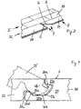
- a preferred embodiment of a quadrangular panel is in Fig. 3 to see which fragmentary represents the production of a floor covering of panels according to the invention.
- the panels used is an embodiment with a first edge pair having complementary hook profiles H, and with a second edge pair, which with complementary form-fitting Swivel profiles S is provided.
- the swivel profiles S are used to connect panels of different panel rows together.
- the hook profiles H serve in this embodiment to connect panels of the same row of panels together.
- the hook profiles H of the first edge pair may be formed as in the embodiment of FIGS. 1a to 1d , Alternatively, the hook profiles H of the first edge pair of the embodiment according to the FIGS. 2a to 2d correspond.
- Fig. 3 shows in the front row of panels III a new panel 27 to be locked with both the previous panel row II and with the adjacent panel 28 of the same panel row III.
- the new panel 27 is slanted with respect to the plane of the laid panels and attached with one of its pivoting profiles S to the front row of panels II. It is then locked by pivoting in the plane of the laid panels with the previous panel row II.
- the hook profile (locking hook 6) of the new panel 27 locks with the hook profile (receiving hook 5) of the panel 28 of the same panel row III.
- the locking hook 6 while the new panel 27 pivots down into the plane of the laid panels, simultaneously brought in a scissor-like joining movement with the receiving hooks 5 in engagement.
- the receiving hook 5 has a bending web whose elastic bending is completed step by step, the further the locking hook 6 is moved in the direction of the receiving hook 5, or the further the locking shoulder of the locking hook 6 is inserted into the receiving recess of the receiving hook 5.
- a complementary pivoting profiles S all known form-fitting profiles in question, which can be positively connect by oblique attachment of a new panel to a previous row of panels and then pivoting down the new panel in the plane of the laid panels.
- An embodiment of such a Swing profile S is in Fig. 4 shown.
- the complementary pivoting profiles S according to Fig. 4 include a groove profile 29 and a spring profile 30.
- the groove profile 29 has an upper groove wall 29a, which is shorter than the lower groove wall 29b.
- the lower groove wall 29 b is also provided with an undercut recess 29 c for the spring profile 30.
- the recess 29c also has a horizontal locking surface 29d.
- the spring profile 30 is provided with a spring upper side 30a, which is arranged substantially parallel to the upper side 7 of the new panel 27.
- the spring lower side 30b has an undercut 30c and a horizontal locking surface 30d which cooperates with the horizontal locking surface 29d of the lower groove wall 29b.
- the inclination of the new panel 27 according to Fig. 3 is in Fig.
Landscapes
- Engineering & Computer Science (AREA)
- Architecture (AREA)
- Civil Engineering (AREA)
- Structural Engineering (AREA)
- Chemical & Material Sciences (AREA)
- Manufacturing & Machinery (AREA)
- Oil, Petroleum & Natural Gas (AREA)
- Organic Chemistry (AREA)
- Combustion & Propulsion (AREA)
- Floor Finish (AREA)
- Connection Of Plates (AREA)
- Slide Fasteners, Snap Fasteners, And Hook Fasteners (AREA)
- Surgical Instruments (AREA)
- Pinball Game Machines (AREA)
- Finishing Walls (AREA)
- Hooks, Suction Cups, And Attachment By Adhesive Means (AREA)
Priority Applications (2)
| Application Number | Priority Date | Filing Date | Title |
|---|---|---|---|
| PL11808611T PL2655761T3 (pl) | 2010-12-22 | 2011-12-13 | Panel |
| EP16182528.6A EP3121348B1 (de) | 2010-12-22 | 2011-12-13 | Paneel |
Applications Claiming Priority (2)
| Application Number | Priority Date | Filing Date | Title |
|---|---|---|---|
| DE102010063976A DE102010063976B4 (de) | 2010-12-22 | 2010-12-22 | Paneel |
| PCT/EP2011/072573 WO2012084604A1 (de) | 2010-12-22 | 2011-12-13 | Paneel |
Related Child Applications (2)
| Application Number | Title | Priority Date | Filing Date |
|---|---|---|---|
| EP16182528.6A Division-Into EP3121348B1 (de) | 2010-12-22 | 2011-12-13 | Paneel |
| EP16182528.6A Division EP3121348B1 (de) | 2010-12-22 | 2011-12-13 | Paneel |
Publications (2)
| Publication Number | Publication Date |
|---|---|
| EP2655761A1 EP2655761A1 (de) | 2013-10-30 |
| EP2655761B1 true EP2655761B1 (de) | 2017-09-13 |
Family
ID=45015440
Family Applications (2)
| Application Number | Title | Priority Date | Filing Date |
|---|---|---|---|
| EP11808611.5A Active EP2655761B1 (de) | 2010-12-22 | 2011-12-13 | Paneel |
| EP16182528.6A Active EP3121348B1 (de) | 2010-12-22 | 2011-12-13 | Paneel |
Family Applications After (1)
| Application Number | Title | Priority Date | Filing Date |
|---|---|---|---|
| EP16182528.6A Active EP3121348B1 (de) | 2010-12-22 | 2011-12-13 | Paneel |
Country Status (16)
| Country | Link |
|---|---|
| US (3) | USRE47496E1 (zh) |
| EP (2) | EP2655761B1 (zh) |
| JP (1) | JP5913360B2 (zh) |
| KR (1) | KR101494563B1 (zh) |
| CN (2) | CN202055464U (zh) |
| BR (1) | BR112013016040B1 (zh) |
| CA (1) | CA2821606C (zh) |
| DE (2) | DE102010063976B4 (zh) |
| ES (2) | ES2651618T3 (zh) |
| HK (1) | HK1172667A1 (zh) |
| MY (1) | MY169659A (zh) |
| PL (2) | PL2655761T3 (zh) |
| PT (2) | PT3121348T (zh) |
| RU (1) | RU2552504C2 (zh) |
| UA (1) | UA110501C2 (zh) |
| WO (1) | WO2012084604A1 (zh) |
Families Citing this family (55)
| Publication number | Priority date | Publication date | Assignee | Title |
|---|---|---|---|---|
| NL2003019C2 (nl) | 2009-06-12 | 2010-12-15 | 4Sight Innovation Bv | Vloerpaneel en vloerbedekking bestaande uit meerdere van dergelijke vloerpanelen. |
| WO2011085306A1 (en) | 2010-01-11 | 2011-07-14 | Mannington Mills, Inc. | Floor covering with interlocking design |
| BR112012017589B1 (pt) | 2010-01-14 | 2019-11-12 | Spanolux N V Div Balterio | montagem de painel de piso |
| US20130097959A1 (en) * | 2010-06-30 | 2013-04-25 | Kreafin Group Sa | Panel With Improved Coupling Means |
| DE102010063976B4 (de) * | 2010-12-22 | 2013-01-17 | Akzenta Paneele + Profile Gmbh | Paneel |
| DE102011086846A1 (de) | 2011-01-28 | 2012-08-02 | Akzenta Paneele + Profile Gmbh | Paneel |
| US8806832B2 (en) | 2011-03-18 | 2014-08-19 | Inotec Global Limited | Vertical joint system and associated surface covering system |
| KR102197543B1 (ko) * | 2011-08-29 | 2020-12-31 | 세라록 이노베이션 에이비 | 플로어 패널용 기계적 잠금 시스템 |
| WO2013044377A1 (en) * | 2011-09-28 | 2013-04-04 | Distribution Duroy Inc. | Covering panel and method for assembling a plurality of same |
| US9216541B2 (en) | 2012-04-04 | 2015-12-22 | Valinge Innovation Ab | Method for producing a mechanical locking system for building panels |
| US8596013B2 (en) | 2012-04-04 | 2013-12-03 | Valinge Innovation Ab | Building panel with a mechanical locking system |
| US20140318895A1 (en) * | 2013-04-29 | 2014-10-30 | John Birk | Adjustable length scaffolding and method therefor |
| US20130313046A1 (en) * | 2012-05-24 | 2013-11-28 | John Birk | Adjustable length scaffolding and method therefor |
| CA3053601C (en) * | 2012-06-19 | 2021-10-05 | Valinge Innovation Ab | A method for dividing a board into a first panel and a second panel, a method of forming a mechanical locking system for locking of a first and a second panel, and building panels |
| WO2014033628A1 (en) | 2012-08-27 | 2014-03-06 | Pergo (Europe) Ab | Panel |
| EP2754772A1 (en) * | 2013-01-11 | 2014-07-16 | Spanolux N.V. Div. Balterio | Floor panel assembly, floor panel and joining members for use therein |
| PT2978909T (pt) | 2013-03-25 | 2018-06-18 | Vaelinge Innovation Ab | Tábuas de piso providas de um sistema de bloqueio mecânico e método para produzir um sistema de bloqueio deste tipo |
| CN103615447A (zh) * | 2013-11-28 | 2014-03-05 | 苏州征之魂专利技术服务有限公司 | 一种t形槽专用卡槽挡位连接冲压件结构及组装方法 |
| AU2015223563B2 (en) * | 2014-02-26 | 2019-03-21 | I4F Licensing Nv | Panel interconnectable with similar panels for forming a covering |
| USD928988S1 (en) | 2014-02-26 | 2021-08-24 | I4F Licensing Nv | Panel interconnectable with similar panels for forming a covering |
| WO2015130160A1 (en) * | 2014-02-26 | 2015-09-03 | Innovations 4 Flooring Holding N.V. | Panel interconnectable with similar panels for forming a covering |
| US9260870B2 (en) * | 2014-03-24 | 2016-02-16 | Ivc N.V. | Set of mutually lockable panels |
| RU2673572C2 (ru) | 2014-03-24 | 2018-11-28 | Флоринг Индастриз Лимитед, Сарл | Набор взаимно блокируемых панелей |
| DE102014106492A1 (de) * | 2014-05-08 | 2015-11-12 | Akzenta Paneele + Profile Gmbh | Paneel |
| FR3024990B1 (fr) * | 2014-08-25 | 2018-11-16 | Gerflor | Panneau de sol pour la realisation d'un revetement. |
| HUE061045T2 (hu) | 2014-08-29 | 2023-05-28 | Vaelinge Innovation Ab | Függõleges illesztékrendszer felületburkoló panelhez |
| NO3031998T3 (zh) | 2014-12-08 | 2018-02-24 | ||
| WO2016105266A1 (en) * | 2014-12-22 | 2016-06-30 | Ceraloc Innovation Ab | Mechanical locking system for floor panels |
| US10072428B2 (en) | 2015-01-15 | 2018-09-11 | Flooring Industries Limited, Sarl | Floor panel for forming a floor covering |
| US10428535B2 (en) | 2015-01-15 | 2019-10-01 | Flooring Industries Limited, Sarl | Floor panel for forming a floor covering |
| WO2016114712A1 (en) | 2015-01-16 | 2016-07-21 | Ceraloc Innovation Ab | Mechanical locking system for floor panels |
| BE1022985B1 (nl) | 2015-01-16 | 2016-10-27 | Flooring Industries Limited Sarl | Vloerpaneel voor het vormen van een vloerbekleding |
| EP3245354A1 (en) * | 2015-01-16 | 2017-11-22 | Flooring Industries Limited, SARL | Floor panel for forming a floor covering |
| CN104675079A (zh) * | 2015-02-13 | 2015-06-03 | 安徽森泰塑木新材料有限公司 | 一种木塑地板 |
| DE102015111929A1 (de) * | 2015-07-22 | 2017-01-26 | Akzenta Paneele + Profile Gmbh | Paneel |
| BE1023545B1 (nl) * | 2015-10-23 | 2017-04-28 | Flooring Industries Limited, Sarl | Set van vloerpanelen voor het vormen van een vloerbekleding |
| US10837181B2 (en) | 2015-12-17 | 2020-11-17 | Valinge Innovation Ab | Method for producing a mechanical locking system for panels |
| US10648182B2 (en) | 2015-12-31 | 2020-05-12 | Flooring Industries Limited, Sarl | Floor panel for forming a floor covering |
| BE1023779B1 (nl) | 2015-12-31 | 2017-07-24 | Flooring Industries Limited Sarl | Vloerpaneel voor het vormen van een vloerbekleding |
| BE1023818B1 (nl) * | 2016-01-15 | 2017-08-01 | Flooring Industries Limited Sarl | Vloerpaneel voor het vormen van een vloerbekleding |
| AU2017335148B2 (en) | 2016-09-30 | 2023-04-20 | Välinge Innovation AB | Set of panels assembled by vertical displacement and locked together in the vertical and horizontal direction |
| ES2910350T3 (es) * | 2017-03-21 | 2022-05-12 | Flooring Ind Ltd Sarl | Panel para la formación de un revestimiento |
| US11015351B2 (en) * | 2017-03-21 | 2021-05-25 | Flooring Industries Limited, Sarl | Floor panel for forming a floor covering |
| NL2018781B1 (en) | 2017-04-26 | 2018-11-05 | Innovations4Flooring Holding N V | Panel and covering |
| US11459774B2 (en) * | 2017-07-18 | 2022-10-04 | Xylo Technologies Ag | Panels with a detachable protruding lip for wall- , ceiling- or floor coverings |
| EP3489431B1 (de) * | 2017-11-24 | 2022-04-13 | Surface Technologies GmbH & Co. KG | Paneel |
| EP3737802B1 (en) | 2018-01-09 | 2023-05-10 | Välinge Innovation AB | Set of panels |
| BE1026099B1 (nl) | 2018-03-16 | 2019-10-14 | Kreafin Group Sa | Paneel waarvan de koppelmiddelen geschikt zijn om de langse zijden en/of kopse zijden onderling met elkaar te verbinden |
| CA3087348A1 (en) | 2018-01-22 | 2019-07-25 | Inovame | Method of manufacturing a plastic covering panel and the panel obtained |
| EP3581732B1 (de) * | 2018-06-15 | 2022-12-07 | Akzenta Paneele + Profile GmbH | Paneel mit dichtungsrille und dichtungsleiste |
| NL2021886B1 (en) * | 2018-10-26 | 2020-05-13 | I4F Licensing Nv | Panel, in particular a floor panel or wall panel, and panel covering |
| AU2020356521A1 (en) * | 2019-09-25 | 2022-03-24 | Välinge Innovation AB | Panel with locking device |
| US20230003034A1 (en) | 2019-12-03 | 2023-01-05 | Flooring Industries Limited, Sarl | Floor panel for forming a floor covering |
| SE544438C2 (en) * | 2019-12-13 | 2022-05-31 | Vilox Ab | Releasable joining system for floor panels, a floor panel, a floor system, a method for laying and a method for releasing a floor panel |
| EP3971364A1 (de) * | 2020-09-17 | 2022-03-23 | Surface Technologies GmbH & Co. KG | Paneel |
Citations (8)
| Publication number | Priority date | Publication date | Assignee | Title |
|---|---|---|---|---|
| US6591568B1 (en) | 2000-03-31 | 2003-07-15 | Pergo (Europe) Ab | Flooring material |
| DE102004001363A1 (de) | 2004-01-07 | 2005-08-04 | Hamberger Industriewerke Gmbh | Verbindung für Fußbodenelemente |
| WO2007020088A1 (de) | 2005-08-19 | 2007-02-22 | Bauer Joerg R | Lösbar aneinander zu befestigende, flächige bauteile, insbesondere bodenbelagsteile, sowie bauteil |
| WO2007141605A2 (en) | 2006-06-02 | 2007-12-13 | Flooring Industries Limited, Sarl | Floor covering, floor element and method for manufacturing floor elements |
| DE202008010555U1 (de) | 2008-08-08 | 2009-12-17 | Akzenta Paneele + Profile Gmbh | Kunststoffpaneel mit Hakenprofil |
| US20100031594A1 (en) | 2008-08-08 | 2010-02-11 | Liu David C | Flooring Boards With Press Down Locking Mechanism |
| EP2339092A1 (en) * | 2009-12-22 | 2011-06-29 | Flooring Industries Limited, SARL | Covering panel and method for installing such panels |
| WO2012001503A1 (en) | 2010-06-30 | 2012-01-05 | Kreafin Group Sa | Panel with improved coupling means |
Family Cites Families (22)
| Publication number | Priority date | Publication date | Assignee | Title |
|---|---|---|---|---|
| DK122829B (da) * | 1970-05-01 | 1972-04-17 | P Bruun | Samling af mindst to bygningsdele samt fremgangsmåde til fremstilling af denne samling. |
| US4426820A (en) * | 1979-04-24 | 1984-01-24 | Heinz Terbrack | Panel for a composite surface and a method of assembling same |
| SE515789C2 (sv) * | 1999-02-10 | 2001-10-08 | Perstorp Flooring Ab | Golvbeläggningsmaterial innefattande golvelement vilka är avsedda att sammanfogas vertikalt |
| DE29911462U1 (de) * | 1999-07-02 | 1999-11-18 | Akzenta Paneele & Profile Gmbh | Befestigungssystem für Paneele |
| RU2224070C2 (ru) * | 1999-06-30 | 2004-02-20 | Акцента Панееле + Профиле Гмбх | Плита, а также система крепления для плит |
| SE522860C2 (sv) * | 2000-03-10 | 2004-03-09 | Pergo Europ Ab | Vertikalt förenade golvelement innefattande en kombination av olika golvelement |
| JP3856617B2 (ja) * | 2000-04-04 | 2006-12-13 | 帝人ファイバー株式会社 | 仮撚加工用ポリエステル繊維 |
| DE20112474U1 (de) * | 2001-07-28 | 2002-12-19 | Kaindl Wals M | Paneel, beispielsweise für Fußboden-, Wand- und/oder Deckenverkleidungen |
| DE10138285A1 (de) * | 2001-08-10 | 2003-03-06 | Akzenta Paneele & Profile Gmbh | Paneel sowie Befestigungssystem für Paneele |
| JP2003213903A (ja) * | 2002-01-28 | 2003-07-30 | Achilles Corp | フロア用板材 |
| DE102004001131B4 (de) * | 2004-01-07 | 2010-04-22 | Akzenta Paneele + Profile Gmbh | Fußbodenpaneel |
| US7841144B2 (en) | 2005-03-30 | 2010-11-30 | Valinge Innovation Ab | Mechanical locking system for panels and method of installing same |
| SI1650375T2 (sl) * | 2004-10-22 | 2011-04-29 | Vaelinge Innovation Ab | Set talnih panelov |
| DE102005028072B4 (de) * | 2005-06-16 | 2010-12-30 | Akzenta Paneele + Profile Gmbh | Fußbodenpaneel |
| DE102006011887A1 (de) * | 2006-01-13 | 2007-07-19 | Akzenta Paneele + Profile Gmbh | Sperrelement, Paneel mit separatem Sperrelement, Verfahren zur Installation eines Paneelbelags aus Paneelen mit Sperrelementen sowie Verfahren und Vorrichtung zur Vormontage eines Sperrelements an einem Paneel |
| DK2009197T3 (en) * | 2006-04-14 | 2016-06-13 | Yekalon Ind Inc | Floor block, floor system and laying method therefore |
| DE102006057491A1 (de) * | 2006-12-06 | 2008-06-12 | Akzenta Paneele + Profile Gmbh | Paneel sowie Bodenbelag |
| KR100978000B1 (ko) * | 2007-04-27 | 2010-08-25 | 주식회사 이지테크 | 수직시공이 가능한 바닥마감용 마루판재 |
| DE102007042840B4 (de) * | 2007-09-10 | 2010-04-22 | Flooring Technologies Ltd. | Paneel, insbesondere Bodenpaneel |
| WO2009061279A1 (en) * | 2007-11-07 | 2009-05-14 | Välinge Innovation AB | Mechanical locking of floor panels with vertical snap folding and an installation method to connect such panels |
| US8365499B2 (en) * | 2009-09-04 | 2013-02-05 | Valinge Innovation Ab | Resilient floor |
| DE102010063976B4 (de) * | 2010-12-22 | 2013-01-17 | Akzenta Paneele + Profile Gmbh | Paneel |
-
2010
- 2010-12-22 DE DE102010063976A patent/DE102010063976B4/de active Active
-
2011
- 2011-04-08 CN CN2011201003333U patent/CN202055464U/zh not_active Expired - Lifetime
- 2011-04-08 CN CN201110087475.5A patent/CN102535811B/zh active Active
- 2011-12-13 EP EP11808611.5A patent/EP2655761B1/de active Active
- 2011-12-13 BR BR112013016040-3A patent/BR112013016040B1/pt active IP Right Grant
- 2011-12-13 ES ES11808611.5T patent/ES2651618T3/es active Active
- 2011-12-13 US US15/944,141 patent/USRE47496E1/en active Active
- 2011-12-13 JP JP2013545183A patent/JP5913360B2/ja active Active
- 2011-12-13 ES ES16182528T patent/ES2927611T3/es active Active
- 2011-12-13 PL PL11808611T patent/PL2655761T3/pl unknown
- 2011-12-13 US US13/996,313 patent/US8720150B2/en not_active Ceased
- 2011-12-13 UA UAA201308708A patent/UA110501C2/ru unknown
- 2011-12-13 PT PT161825286T patent/PT3121348T/pt unknown
- 2011-12-13 DE DE202011110833.7U patent/DE202011110833U1/de not_active Expired - Lifetime
- 2011-12-13 RU RU2013133451/03A patent/RU2552504C2/ru active
- 2011-12-13 EP EP16182528.6A patent/EP3121348B1/de active Active
- 2011-12-13 PT PT118086115T patent/PT2655761T/pt unknown
- 2011-12-13 KR KR1020137019099A patent/KR101494563B1/ko active IP Right Grant
- 2011-12-13 MY MYPI2013002325A patent/MY169659A/en unknown
- 2011-12-13 WO PCT/EP2011/072573 patent/WO2012084604A1/de active Application Filing
- 2011-12-13 CA CA2821606A patent/CA2821606C/en active Active
- 2011-12-13 PL PL16182528.6T patent/PL3121348T3/pl unknown
-
2012
- 2012-12-27 HK HK12113458.4A patent/HK1172667A1/zh unknown
-
2014
- 2014-03-20 US US14/220,741 patent/US9175475B2/en active Active
Patent Citations (8)
| Publication number | Priority date | Publication date | Assignee | Title |
|---|---|---|---|---|
| US6591568B1 (en) | 2000-03-31 | 2003-07-15 | Pergo (Europe) Ab | Flooring material |
| DE102004001363A1 (de) | 2004-01-07 | 2005-08-04 | Hamberger Industriewerke Gmbh | Verbindung für Fußbodenelemente |
| WO2007020088A1 (de) | 2005-08-19 | 2007-02-22 | Bauer Joerg R | Lösbar aneinander zu befestigende, flächige bauteile, insbesondere bodenbelagsteile, sowie bauteil |
| WO2007141605A2 (en) | 2006-06-02 | 2007-12-13 | Flooring Industries Limited, Sarl | Floor covering, floor element and method for manufacturing floor elements |
| DE202008010555U1 (de) | 2008-08-08 | 2009-12-17 | Akzenta Paneele + Profile Gmbh | Kunststoffpaneel mit Hakenprofil |
| US20100031594A1 (en) | 2008-08-08 | 2010-02-11 | Liu David C | Flooring Boards With Press Down Locking Mechanism |
| EP2339092A1 (en) * | 2009-12-22 | 2011-06-29 | Flooring Industries Limited, SARL | Covering panel and method for installing such panels |
| WO2012001503A1 (en) | 2010-06-30 | 2012-01-05 | Kreafin Group Sa | Panel with improved coupling means |
Also Published As
Similar Documents
| Publication | Publication Date | Title |
|---|---|---|
| EP2655761B1 (de) | Paneel | |
| EP2668350B1 (de) | Paneel | |
| EP3031998B1 (de) | Paneel mit einem hakenförmigen Verriegelungssystem | |
| EP1891283B1 (de) | Fussbodenpaneel mit einem holzwerkstoffkern, einer dekorschicht und verriegelungsprofilen | |
| EP2057327B1 (de) | Paneel, insbesondere bodenpaneel | |
| DE202009004530U1 (de) | Fußbodenpaneel | |
| DE202016102034U1 (de) | Fußbodenpaneel zur Bildung eines Fußbodenbelags | |
| DE202008008597U1 (de) | Fußbodenpaneel | |
| DE202010018552U1 (de) | Paneel | |
| EP2318613A1 (de) | FUßBODENPANEEL AUS KUNSTSTOFF MIT MECHANISCHEN VERRIEGELUNGSKANTEN | |
| DE10214972A1 (de) | Paneel sowie Verriegelungssystem für Paneele | |
| DE202012104530U1 (de) | Set aus Paneelen mit Clip | |
| EP3117055B1 (de) | Belag aus mechanisch miteinander verbindbaren paneelen | |
| WO2012069485A1 (de) | FUßBODENPANEEL MIT WEICHELASTISCHER NUTZSCHICHT | |
| DE202010017178U1 (de) | Paneel | |
| EP2995747B1 (de) | Mechanische verbindung für paneele und verfahren zur montage einer verriegelungsfeder in einem paneel | |
| WO2013023639A1 (de) | Belag aus mechanisch miteinander verbindbaren paneelen | |
| EP2415944B1 (de) | Fußbodenpaneel mit einer Verbindungseinrichtung | |
| DE102016114226A1 (de) | Verbindung für elastische oder feste Bauelemente | |
| EP3080365A1 (de) | Paneel mit verriegelungselement |
Legal Events
| Date | Code | Title | Description |
|---|---|---|---|
| PUAI | Public reference made under article 153(3) epc to a published international application that has entered the european phase |
Free format text: ORIGINAL CODE: 0009012 |
|
| 17P | Request for examination filed |
Effective date: 20130613 |
|
| AK | Designated contracting states |
Kind code of ref document: A1 Designated state(s): AL AT BE BG CH CY CZ DE DK EE ES FI FR GB GR HR HU IE IS IT LI LT LU LV MC MK MT NL NO PL PT RO RS SE SI SK SM TR |
|
| DAX | Request for extension of the european patent (deleted) | ||
| GRAP | Despatch of communication of intention to grant a patent |
Free format text: ORIGINAL CODE: EPIDOSNIGR1 |
|
| STAA | Information on the status of an ep patent application or granted ep patent |
Free format text: STATUS: GRANT OF PATENT IS INTENDED |
|
| INTG | Intention to grant announced |
Effective date: 20170223 |
|
| GRAJ | Information related to disapproval of communication of intention to grant by the applicant or resumption of examination proceedings by the epo deleted |
Free format text: ORIGINAL CODE: EPIDOSDIGR1 |
|
| GRAL | Information related to payment of fee for publishing/printing deleted |
Free format text: ORIGINAL CODE: EPIDOSDIGR3 |
|
| GRAS | Grant fee paid |
Free format text: ORIGINAL CODE: EPIDOSNIGR3 |
|
| STAA | Information on the status of an ep patent application or granted ep patent |
Free format text: STATUS: REQUEST FOR EXAMINATION WAS MADE |
|
| GRAJ | Information related to disapproval of communication of intention to grant by the applicant or resumption of examination proceedings by the epo deleted |
Free format text: ORIGINAL CODE: EPIDOSDIGR1 |
|
| GRAP | Despatch of communication of intention to grant a patent |
Free format text: ORIGINAL CODE: EPIDOSNIGR1 |
|
| RBV | Designated contracting states (corrected) |
Designated state(s): AL AT BE BG CH CY CZ DK EE ES FI FR GB GR HR HU IE IS IT LI LT LU LV MC MK MT NL NO PL PT RO RS SE SI SK SM TR |
|
| REG | Reference to a national code |
Ref country code: DE Ref legal event code: R108 |
|
| GRAP | Despatch of communication of intention to grant a patent |
Free format text: ORIGINAL CODE: EPIDOSNIGR1 |
|
| STAA | Information on the status of an ep patent application or granted ep patent |
Free format text: STATUS: GRANT OF PATENT IS INTENDED |
|
| INTC | Intention to grant announced (deleted) | ||
| RIC1 | Information provided on ipc code assigned before grant |
Ipc: E04C 2/38 20060101ALN20170619BHEP Ipc: E04F 15/02 20060101ALI20170619BHEP Ipc: E04F 15/10 20060101AFI20170619BHEP |
|
| INTG | Intention to grant announced |
Effective date: 20170714 |
|
| GRAA | (expected) grant |
Free format text: ORIGINAL CODE: 0009210 |
|
| STAA | Information on the status of an ep patent application or granted ep patent |
Free format text: STATUS: THE PATENT HAS BEEN GRANTED |
|
| AK | Designated contracting states |
Kind code of ref document: B1 Designated state(s): AL AT BE BG CH CY CZ DK EE ES FI FR GB GR HR HU IE IS IT LI LT LU LV MC MK MT NL NO PL PT RO RS SE SI SK SM TR |
|
| REG | Reference to a national code |
Ref country code: GB Ref legal event code: FG4D Free format text: NOT ENGLISH |
|
| REG | Reference to a national code |
Ref country code: CH Ref legal event code: EP |
|
| REG | Reference to a national code |
Ref country code: IE Ref legal event code: FG4D Free format text: LANGUAGE OF EP DOCUMENT: GERMAN |
|
| REG | Reference to a national code |
Ref country code: AT Ref legal event code: REF Ref document number: 928294 Country of ref document: AT Kind code of ref document: T Effective date: 20171015 |
|
| REG | Reference to a national code |
Ref country code: CH Ref legal event code: NV Representative=s name: KATZAROV S.A., CH |
|
| REG | Reference to a national code |
Ref country code: PT Ref legal event code: SC4A Ref document number: 2655761 Country of ref document: PT Date of ref document: 20171214 Kind code of ref document: T Free format text: AVAILABILITY OF NATIONAL TRANSLATION Effective date: 20171206 |
|
| REG | Reference to a national code |
Ref country code: FR Ref legal event code: PLFP Year of fee payment: 7 |
|
| REG | Reference to a national code |
Ref country code: NL Ref legal event code: FP |
|
| REG | Reference to a national code |
Ref country code: LT Ref legal event code: MG4D |
|
| REG | Reference to a national code |
Ref country code: ES Ref legal event code: FG2A Ref document number: 2651618 Country of ref document: ES Kind code of ref document: T3 Effective date: 20180129 |
|
| PG25 | Lapsed in a contracting state [announced via postgrant information from national office to epo] |
Ref country code: SE Free format text: LAPSE BECAUSE OF FAILURE TO SUBMIT A TRANSLATION OF THE DESCRIPTION OR TO PAY THE FEE WITHIN THE PRESCRIBED TIME-LIMIT Effective date: 20170913 Ref country code: NO Free format text: LAPSE BECAUSE OF FAILURE TO SUBMIT A TRANSLATION OF THE DESCRIPTION OR TO PAY THE FEE WITHIN THE PRESCRIBED TIME-LIMIT Effective date: 20171213 Ref country code: FI Free format text: LAPSE BECAUSE OF FAILURE TO SUBMIT A TRANSLATION OF THE DESCRIPTION OR TO PAY THE FEE WITHIN THE PRESCRIBED TIME-LIMIT Effective date: 20170913 Ref country code: HR Free format text: LAPSE BECAUSE OF FAILURE TO SUBMIT A TRANSLATION OF THE DESCRIPTION OR TO PAY THE FEE WITHIN THE PRESCRIBED TIME-LIMIT Effective date: 20170913 Ref country code: LT Free format text: LAPSE BECAUSE OF FAILURE TO SUBMIT A TRANSLATION OF THE DESCRIPTION OR TO PAY THE FEE WITHIN THE PRESCRIBED TIME-LIMIT Effective date: 20170913 |
|
| PG25 | Lapsed in a contracting state [announced via postgrant information from national office to epo] |
Ref country code: RS Free format text: LAPSE BECAUSE OF FAILURE TO SUBMIT A TRANSLATION OF THE DESCRIPTION OR TO PAY THE FEE WITHIN THE PRESCRIBED TIME-LIMIT Effective date: 20170913 Ref country code: LV Free format text: LAPSE BECAUSE OF FAILURE TO SUBMIT A TRANSLATION OF THE DESCRIPTION OR TO PAY THE FEE WITHIN THE PRESCRIBED TIME-LIMIT Effective date: 20170913 Ref country code: GR Free format text: LAPSE BECAUSE OF FAILURE TO SUBMIT A TRANSLATION OF THE DESCRIPTION OR TO PAY THE FEE WITHIN THE PRESCRIBED TIME-LIMIT Effective date: 20171214 Ref country code: BG Free format text: LAPSE BECAUSE OF FAILURE TO SUBMIT A TRANSLATION OF THE DESCRIPTION OR TO PAY THE FEE WITHIN THE PRESCRIBED TIME-LIMIT Effective date: 20171213 |
|
| REG | Reference to a national code |
Ref country code: CH Ref legal event code: PCAR Free format text: NEW ADDRESS: AVENUE DES MORGINES 12, 1213 PETIT-LANCY (CH) |
|
| PG25 | Lapsed in a contracting state [announced via postgrant information from national office to epo] |
Ref country code: RO Free format text: LAPSE BECAUSE OF FAILURE TO SUBMIT A TRANSLATION OF THE DESCRIPTION OR TO PAY THE FEE WITHIN THE PRESCRIBED TIME-LIMIT Effective date: 20170913 |
|
| PG25 | Lapsed in a contracting state [announced via postgrant information from national office to epo] |
Ref country code: SK Free format text: LAPSE BECAUSE OF FAILURE TO SUBMIT A TRANSLATION OF THE DESCRIPTION OR TO PAY THE FEE WITHIN THE PRESCRIBED TIME-LIMIT Effective date: 20170913 Ref country code: IS Free format text: LAPSE BECAUSE OF FAILURE TO SUBMIT A TRANSLATION OF THE DESCRIPTION OR TO PAY THE FEE WITHIN THE PRESCRIBED TIME-LIMIT Effective date: 20180113 Ref country code: SM Free format text: LAPSE BECAUSE OF FAILURE TO SUBMIT A TRANSLATION OF THE DESCRIPTION OR TO PAY THE FEE WITHIN THE PRESCRIBED TIME-LIMIT Effective date: 20170913 Ref country code: EE Free format text: LAPSE BECAUSE OF FAILURE TO SUBMIT A TRANSLATION OF THE DESCRIPTION OR TO PAY THE FEE WITHIN THE PRESCRIBED TIME-LIMIT Effective date: 20170913 |
|
| PLBI | Opposition filed |
Free format text: ORIGINAL CODE: 0009260 |
|
| PLAX | Notice of opposition and request to file observation + time limit sent |
Free format text: ORIGINAL CODE: EPIDOSNOBS2 |
|
| 26 | Opposition filed |
Opponent name: KREAFIN GROUP SA Effective date: 20180613 |
|
| PG25 | Lapsed in a contracting state [announced via postgrant information from national office to epo] |
Ref country code: DK Free format text: LAPSE BECAUSE OF FAILURE TO SUBMIT A TRANSLATION OF THE DESCRIPTION OR TO PAY THE FEE WITHIN THE PRESCRIBED TIME-LIMIT Effective date: 20170913 |
|
| REG | Reference to a national code |
Ref country code: IE Ref legal event code: MM4A |
|
| PG25 | Lapsed in a contracting state [announced via postgrant information from national office to epo] |
Ref country code: MT Free format text: LAPSE BECAUSE OF FAILURE TO SUBMIT A TRANSLATION OF THE DESCRIPTION OR TO PAY THE FEE WITHIN THE PRESCRIBED TIME-LIMIT Effective date: 20170913 Ref country code: LU Free format text: LAPSE BECAUSE OF NON-PAYMENT OF DUE FEES Effective date: 20171213 |
|
| PG25 | Lapsed in a contracting state [announced via postgrant information from national office to epo] |
Ref country code: IE Free format text: LAPSE BECAUSE OF NON-PAYMENT OF DUE FEES Effective date: 20171213 |
|
| PLBB | Reply of patent proprietor to notice(s) of opposition received |
Free format text: ORIGINAL CODE: EPIDOSNOBS3 |
|
| PG25 | Lapsed in a contracting state [announced via postgrant information from national office to epo] |
Ref country code: SI Free format text: LAPSE BECAUSE OF FAILURE TO SUBMIT A TRANSLATION OF THE DESCRIPTION OR TO PAY THE FEE WITHIN THE PRESCRIBED TIME-LIMIT Effective date: 20170913 |
|
| PG25 | Lapsed in a contracting state [announced via postgrant information from national office to epo] |
Ref country code: MC Free format text: LAPSE BECAUSE OF FAILURE TO SUBMIT A TRANSLATION OF THE DESCRIPTION OR TO PAY THE FEE WITHIN THE PRESCRIBED TIME-LIMIT Effective date: 20170913 Ref country code: HU Free format text: LAPSE BECAUSE OF FAILURE TO SUBMIT A TRANSLATION OF THE DESCRIPTION OR TO PAY THE FEE WITHIN THE PRESCRIBED TIME-LIMIT; INVALID AB INITIO Effective date: 20111213 |
|
| PG25 | Lapsed in a contracting state [announced via postgrant information from national office to epo] |
Ref country code: CY Free format text: LAPSE BECAUSE OF NON-PAYMENT OF DUE FEES Effective date: 20170913 |
|
| PG25 | Lapsed in a contracting state [announced via postgrant information from national office to epo] |
Ref country code: MK Free format text: LAPSE BECAUSE OF FAILURE TO SUBMIT A TRANSLATION OF THE DESCRIPTION OR TO PAY THE FEE WITHIN THE PRESCRIBED TIME-LIMIT Effective date: 20170913 |
|
| PLCK | Communication despatched that opposition was rejected |
Free format text: ORIGINAL CODE: EPIDOSNREJ1 |
|
| PLBN | Opposition rejected |
Free format text: ORIGINAL CODE: 0009273 |
|
| STAA | Information on the status of an ep patent application or granted ep patent |
Free format text: STATUS: OPPOSITION REJECTED |
|
| PG25 | Lapsed in a contracting state [announced via postgrant information from national office to epo] |
Ref country code: AL Free format text: LAPSE BECAUSE OF FAILURE TO SUBMIT A TRANSLATION OF THE DESCRIPTION OR TO PAY THE FEE WITHIN THE PRESCRIBED TIME-LIMIT Effective date: 20170913 |
|
| 27O | Opposition rejected |
Effective date: 20200319 |
|
| PGFP | Annual fee paid to national office [announced via postgrant information from national office to epo] |
Ref country code: IT Payment date: 20221230 Year of fee payment: 12 |
|
| P01 | Opt-out of the competence of the unified patent court (upc) registered |
Effective date: 20230526 |
|
| PGFP | Annual fee paid to national office [announced via postgrant information from national office to epo] |
Ref country code: GB Payment date: 20231220 Year of fee payment: 13 |
|
| PGFP | Annual fee paid to national office [announced via postgrant information from national office to epo] |
Ref country code: TR Payment date: 20231205 Year of fee payment: 13 Ref country code: PT Payment date: 20231130 Year of fee payment: 13 Ref country code: NL Payment date: 20231219 Year of fee payment: 13 Ref country code: FR Payment date: 20231219 Year of fee payment: 13 Ref country code: CZ Payment date: 20231130 Year of fee payment: 13 Ref country code: AT Payment date: 20231214 Year of fee payment: 13 |
|
| PGFP | Annual fee paid to national office [announced via postgrant information from national office to epo] |
Ref country code: PL Payment date: 20231201 Year of fee payment: 13 Ref country code: BE Payment date: 20231218 Year of fee payment: 13 |
|
| PGFP | Annual fee paid to national office [announced via postgrant information from national office to epo] |
Ref country code: ES Payment date: 20240118 Year of fee payment: 13 |
|
| PGFP | Annual fee paid to national office [announced via postgrant information from national office to epo] |
Ref country code: CH Payment date: 20240110 Year of fee payment: 13 |