EP2636484B1 - Vorrichtung zum Bearbeiten von Brillengläsern - Google Patents
Vorrichtung zum Bearbeiten von Brillengläsern Download PDFInfo
- Publication number
- EP2636484B1 EP2636484B1 EP13001157.0A EP13001157A EP2636484B1 EP 2636484 B1 EP2636484 B1 EP 2636484B1 EP 13001157 A EP13001157 A EP 13001157A EP 2636484 B1 EP2636484 B1 EP 2636484B1
- Authority
- EP
- European Patent Office
- Prior art keywords
- lens
- processing
- shaft
- processing tool
- eyeglass lens
- Prior art date
- Legal status (The legal status is an assumption and is not a legal conclusion. Google has not performed a legal analysis and makes no representation as to the accuracy of the status listed.)
- Active
Links
Images


Classifications
-
- B—PERFORMING OPERATIONS; TRANSPORTING
- B23—MACHINE TOOLS; METAL-WORKING NOT OTHERWISE PROVIDED FOR
- B23Q—DETAILS, COMPONENTS, OR ACCESSORIES FOR MACHINE TOOLS, e.g. ARRANGEMENTS FOR COPYING OR CONTROLLING; MACHINE TOOLS IN GENERAL CHARACTERISED BY THE CONSTRUCTION OF PARTICULAR DETAILS OR COMPONENTS; COMBINATIONS OR ASSOCIATIONS OF METAL-WORKING MACHINES, NOT DIRECTED TO A PARTICULAR RESULT
- B23Q1/00—Members which are comprised in the general build-up of a form of machine, particularly relatively large fixed members
- B23Q1/25—Movable or adjustable work or tool supports
- B23Q1/64—Movable or adjustable work or tool supports characterised by the purpose of the movement
-
- B—PERFORMING OPERATIONS; TRANSPORTING
- B23—MACHINE TOOLS; METAL-WORKING NOT OTHERWISE PROVIDED FOR
- B23Q—DETAILS, COMPONENTS, OR ACCESSORIES FOR MACHINE TOOLS, e.g. ARRANGEMENTS FOR COPYING OR CONTROLLING; MACHINE TOOLS IN GENERAL CHARACTERISED BY THE CONSTRUCTION OF PARTICULAR DETAILS OR COMPONENTS; COMBINATIONS OR ASSOCIATIONS OF METAL-WORKING MACHINES, NOT DIRECTED TO A PARTICULAR RESULT
- B23Q1/00—Members which are comprised in the general build-up of a form of machine, particularly relatively large fixed members
- B23Q1/25—Movable or adjustable work or tool supports
- B23Q1/44—Movable or adjustable work or tool supports using particular mechanisms
- B23Q1/48—Movable or adjustable work or tool supports using particular mechanisms with sliding pairs and rotating pairs
- B23Q1/4876—Movable or adjustable work or tool supports using particular mechanisms with sliding pairs and rotating pairs a single sliding pair followed parallelly by a single rotating pair
- B23Q1/488—Movable or adjustable work or tool supports using particular mechanisms with sliding pairs and rotating pairs a single sliding pair followed parallelly by a single rotating pair followed perpendicularly by a single rotating pair
-
- B—PERFORMING OPERATIONS; TRANSPORTING
- B23—MACHINE TOOLS; METAL-WORKING NOT OTHERWISE PROVIDED FOR
- B23Q—DETAILS, COMPONENTS, OR ACCESSORIES FOR MACHINE TOOLS, e.g. ARRANGEMENTS FOR COPYING OR CONTROLLING; MACHINE TOOLS IN GENERAL CHARACTERISED BY THE CONSTRUCTION OF PARTICULAR DETAILS OR COMPONENTS; COMBINATIONS OR ASSOCIATIONS OF METAL-WORKING MACHINES, NOT DIRECTED TO A PARTICULAR RESULT
- B23Q39/00—Metal-working machines incorporating a plurality of sub-assemblies, each capable of performing a metal-working operation
- B23Q39/02—Metal-working machines incorporating a plurality of sub-assemblies, each capable of performing a metal-working operation the sub-assemblies being capable of being brought to act at a single operating station
- B23Q39/021—Metal-working machines incorporating a plurality of sub-assemblies, each capable of performing a metal-working operation the sub-assemblies being capable of being brought to act at a single operating station with a plurality of toolheads per workholder, whereby the toolhead is a main spindle, a multispindle, a revolver or the like
- B23Q39/025—Metal-working machines incorporating a plurality of sub-assemblies, each capable of performing a metal-working operation the sub-assemblies being capable of being brought to act at a single operating station with a plurality of toolheads per workholder, whereby the toolhead is a main spindle, a multispindle, a revolver or the like with different working directions of toolheads on same workholder
- B23Q39/027—Metal-working machines incorporating a plurality of sub-assemblies, each capable of performing a metal-working operation the sub-assemblies being capable of being brought to act at a single operating station with a plurality of toolheads per workholder, whereby the toolhead is a main spindle, a multispindle, a revolver or the like with different working directions of toolheads on same workholder consecutive working of toolheads
-
- B—PERFORMING OPERATIONS; TRANSPORTING
- B24—GRINDING; POLISHING
- B24B—MACHINES, DEVICES, OR PROCESSES FOR GRINDING OR POLISHING; DRESSING OR CONDITIONING OF ABRADING SURFACES; FEEDING OF GRINDING, POLISHING, OR LAPPING AGENTS
- B24B27/00—Other grinding machines or devices
- B24B27/0069—Other grinding machines or devices with means for feeding the work-pieces to the grinding tool, e.g. turntables, transfer means
-
- B—PERFORMING OPERATIONS; TRANSPORTING
- B24—GRINDING; POLISHING
- B24B—MACHINES, DEVICES, OR PROCESSES FOR GRINDING OR POLISHING; DRESSING OR CONDITIONING OF ABRADING SURFACES; FEEDING OF GRINDING, POLISHING, OR LAPPING AGENTS
- B24B27/00—Other grinding machines or devices
- B24B27/0076—Other grinding machines or devices grinding machines comprising two or more grinding tools
-
- B—PERFORMING OPERATIONS; TRANSPORTING
- B24—GRINDING; POLISHING
- B24B—MACHINES, DEVICES, OR PROCESSES FOR GRINDING OR POLISHING; DRESSING OR CONDITIONING OF ABRADING SURFACES; FEEDING OF GRINDING, POLISHING, OR LAPPING AGENTS
- B24B41/00—Component parts such as frames, beds, carriages, headstocks
- B24B41/005—Feeding or manipulating devices specially adapted to grinding machines
-
- B—PERFORMING OPERATIONS; TRANSPORTING
- B24—GRINDING; POLISHING
- B24B—MACHINES, DEVICES, OR PROCESSES FOR GRINDING OR POLISHING; DRESSING OR CONDITIONING OF ABRADING SURFACES; FEEDING OF GRINDING, POLISHING, OR LAPPING AGENTS
- B24B9/00—Machines or devices designed for grinding edges or bevels on work or for removing burrs; Accessories therefor
- B24B9/02—Machines or devices designed for grinding edges or bevels on work or for removing burrs; Accessories therefor characterised by a special design with respect to properties of materials specific to articles to be ground
- B24B9/06—Machines or devices designed for grinding edges or bevels on work or for removing burrs; Accessories therefor characterised by a special design with respect to properties of materials specific to articles to be ground of non-metallic inorganic material, e.g. stone, ceramics, porcelain
- B24B9/08—Machines or devices designed for grinding edges or bevels on work or for removing burrs; Accessories therefor characterised by a special design with respect to properties of materials specific to articles to be ground of non-metallic inorganic material, e.g. stone, ceramics, porcelain of glass
- B24B9/14—Machines or devices designed for grinding edges or bevels on work or for removing burrs; Accessories therefor characterised by a special design with respect to properties of materials specific to articles to be ground of non-metallic inorganic material, e.g. stone, ceramics, porcelain of glass of optical work, e.g. lenses, prisms
- B24B9/146—Accessories, e.g. lens mounting devices
-
- B—PERFORMING OPERATIONS; TRANSPORTING
- B24—GRINDING; POLISHING
- B24B—MACHINES, DEVICES, OR PROCESSES FOR GRINDING OR POLISHING; DRESSING OR CONDITIONING OF ABRADING SURFACES; FEEDING OF GRINDING, POLISHING, OR LAPPING AGENTS
- B24B9/00—Machines or devices designed for grinding edges or bevels on work or for removing burrs; Accessories therefor
- B24B9/02—Machines or devices designed for grinding edges or bevels on work or for removing burrs; Accessories therefor characterised by a special design with respect to properties of materials specific to articles to be ground
- B24B9/06—Machines or devices designed for grinding edges or bevels on work or for removing burrs; Accessories therefor characterised by a special design with respect to properties of materials specific to articles to be ground of non-metallic inorganic material, e.g. stone, ceramics, porcelain
- B24B9/08—Machines or devices designed for grinding edges or bevels on work or for removing burrs; Accessories therefor characterised by a special design with respect to properties of materials specific to articles to be ground of non-metallic inorganic material, e.g. stone, ceramics, porcelain of glass
- B24B9/14—Machines or devices designed for grinding edges or bevels on work or for removing burrs; Accessories therefor characterised by a special design with respect to properties of materials specific to articles to be ground of non-metallic inorganic material, e.g. stone, ceramics, porcelain of glass of optical work, e.g. lenses, prisms
- B24B9/148—Machines or devices designed for grinding edges or bevels on work or for removing burrs; Accessories therefor characterised by a special design with respect to properties of materials specific to articles to be ground of non-metallic inorganic material, e.g. stone, ceramics, porcelain of glass of optical work, e.g. lenses, prisms electrically, e.g. numerically, controlled
-
- B—PERFORMING OPERATIONS; TRANSPORTING
- B28—WORKING CEMENT, CLAY, OR STONE
- B28D—WORKING STONE OR STONE-LIKE MATERIALS
- B28D1/00—Working stone or stone-like materials, e.g. brick, concrete or glass, not provided for elsewhere; Machines, devices, tools therefor
- B28D1/14—Working stone or stone-like materials, e.g. brick, concrete or glass, not provided for elsewhere; Machines, devices, tools therefor by boring or drilling
- B28D1/143—Working stone or stone-like materials, e.g. brick, concrete or glass, not provided for elsewhere; Machines, devices, tools therefor by boring or drilling lens-drilling machines
-
- G—PHYSICS
- G05—CONTROLLING; REGULATING
- G05B—CONTROL OR REGULATING SYSTEMS IN GENERAL; FUNCTIONAL ELEMENTS OF SUCH SYSTEMS; MONITORING OR TESTING ARRANGEMENTS FOR SUCH SYSTEMS OR ELEMENTS
- G05B19/00—Programme-control systems
- G05B19/02—Programme-control systems electric
- G05B19/18—Numerical control [NC], i.e. automatically operating machines, in particular machine tools, e.g. in a manufacturing environment, so as to execute positioning, movement or co-ordinated operations by means of programme data in numerical form
- G05B19/401—Numerical control [NC], i.e. automatically operating machines, in particular machine tools, e.g. in a manufacturing environment, so as to execute positioning, movement or co-ordinated operations by means of programme data in numerical form characterised by control arrangements for measuring, e.g. calibration and initialisation, measuring workpiece for machining purposes
-
- G—PHYSICS
- G05—CONTROLLING; REGULATING
- G05B—CONTROL OR REGULATING SYSTEMS IN GENERAL; FUNCTIONAL ELEMENTS OF SUCH SYSTEMS; MONITORING OR TESTING ARRANGEMENTS FOR SUCH SYSTEMS OR ELEMENTS
- G05B19/00—Programme-control systems
- G05B19/02—Programme-control systems electric
- G05B19/18—Numerical control [NC], i.e. automatically operating machines, in particular machine tools, e.g. in a manufacturing environment, so as to execute positioning, movement or co-ordinated operations by means of programme data in numerical form
- G05B19/4093—Numerical control [NC], i.e. automatically operating machines, in particular machine tools, e.g. in a manufacturing environment, so as to execute positioning, movement or co-ordinated operations by means of programme data in numerical form characterised by part programming, e.g. entry of geometrical information as taken from a technical drawing, combining this with machining and material information to obtain control information, named part programme, for the NC machine
- G05B19/40937—Numerical control [NC], i.e. automatically operating machines, in particular machine tools, e.g. in a manufacturing environment, so as to execute positioning, movement or co-ordinated operations by means of programme data in numerical form characterised by part programming, e.g. entry of geometrical information as taken from a technical drawing, combining this with machining and material information to obtain control information, named part programme, for the NC machine concerning programming of machining or material parameters, pocket machining
- G05B19/40938—Tool management
-
- B—PERFORMING OPERATIONS; TRANSPORTING
- B23—MACHINE TOOLS; METAL-WORKING NOT OTHERWISE PROVIDED FOR
- B23Q—DETAILS, COMPONENTS, OR ACCESSORIES FOR MACHINE TOOLS, e.g. ARRANGEMENTS FOR COPYING OR CONTROLLING; MACHINE TOOLS IN GENERAL CHARACTERISED BY THE CONSTRUCTION OF PARTICULAR DETAILS OR COMPONENTS; COMBINATIONS OR ASSOCIATIONS OF METAL-WORKING MACHINES, NOT DIRECTED TO A PARTICULAR RESULT
- B23Q11/00—Accessories fitted to machine tools for keeping tools or parts of the machine in good working condition or for cooling work; Safety devices specially combined with or arranged in, or specially adapted for use in connection with, machine tools
- B23Q11/0042—Devices for removing chips
- B23Q11/005—Devices for removing chips by blowing
-
- B—PERFORMING OPERATIONS; TRANSPORTING
- B23—MACHINE TOOLS; METAL-WORKING NOT OTHERWISE PROVIDED FOR
- B23Q—DETAILS, COMPONENTS, OR ACCESSORIES FOR MACHINE TOOLS, e.g. ARRANGEMENTS FOR COPYING OR CONTROLLING; MACHINE TOOLS IN GENERAL CHARACTERISED BY THE CONSTRUCTION OF PARTICULAR DETAILS OR COMPONENTS; COMBINATIONS OR ASSOCIATIONS OF METAL-WORKING MACHINES, NOT DIRECTED TO A PARTICULAR RESULT
- B23Q11/00—Accessories fitted to machine tools for keeping tools or parts of the machine in good working condition or for cooling work; Safety devices specially combined with or arranged in, or specially adapted for use in connection with, machine tools
- B23Q11/10—Arrangements for cooling or lubricating tools or work
-
- B—PERFORMING OPERATIONS; TRANSPORTING
- B23—MACHINE TOOLS; METAL-WORKING NOT OTHERWISE PROVIDED FOR
- B23Q—DETAILS, COMPONENTS, OR ACCESSORIES FOR MACHINE TOOLS, e.g. ARRANGEMENTS FOR COPYING OR CONTROLLING; MACHINE TOOLS IN GENERAL CHARACTERISED BY THE CONSTRUCTION OF PARTICULAR DETAILS OR COMPONENTS; COMBINATIONS OR ASSOCIATIONS OF METAL-WORKING MACHINES, NOT DIRECTED TO A PARTICULAR RESULT
- B23Q17/00—Arrangements for observing, indicating or measuring on machine tools
- B23Q17/20—Arrangements for observing, indicating or measuring on machine tools for indicating or measuring workpiece characteristics, e.g. contour, dimension, hardness
-
- B—PERFORMING OPERATIONS; TRANSPORTING
- B23—MACHINE TOOLS; METAL-WORKING NOT OTHERWISE PROVIDED FOR
- B23Q—DETAILS, COMPONENTS, OR ACCESSORIES FOR MACHINE TOOLS, e.g. ARRANGEMENTS FOR COPYING OR CONTROLLING; MACHINE TOOLS IN GENERAL CHARACTERISED BY THE CONSTRUCTION OF PARTICULAR DETAILS OR COMPONENTS; COMBINATIONS OR ASSOCIATIONS OF METAL-WORKING MACHINES, NOT DIRECTED TO A PARTICULAR RESULT
- B23Q39/00—Metal-working machines incorporating a plurality of sub-assemblies, each capable of performing a metal-working operation
- B23Q2039/006—Machines with multi-spindles
-
- G—PHYSICS
- G05—CONTROLLING; REGULATING
- G05B—CONTROL OR REGULATING SYSTEMS IN GENERAL; FUNCTIONAL ELEMENTS OF SUCH SYSTEMS; MONITORING OR TESTING ARRANGEMENTS FOR SUCH SYSTEMS OR ELEMENTS
- G05B2219/00—Program-control systems
- G05B2219/30—Nc systems
- G05B2219/45—Nc applications
- G05B2219/45157—Grind optical lens
-
- Y—GENERAL TAGGING OF NEW TECHNOLOGICAL DEVELOPMENTS; GENERAL TAGGING OF CROSS-SECTIONAL TECHNOLOGIES SPANNING OVER SEVERAL SECTIONS OF THE IPC; TECHNICAL SUBJECTS COVERED BY FORMER USPC CROSS-REFERENCE ART COLLECTIONS [XRACs] AND DIGESTS
- Y02—TECHNOLOGIES OR APPLICATIONS FOR MITIGATION OR ADAPTATION AGAINST CLIMATE CHANGE
- Y02P—CLIMATE CHANGE MITIGATION TECHNOLOGIES IN THE PRODUCTION OR PROCESSING OF GOODS
- Y02P90/00—Enabling technologies with a potential contribution to greenhouse gas [GHG] emissions mitigation
- Y02P90/02—Total factory control, e.g. smart factories, flexible manufacturing systems [FMS] or integrated manufacturing systems [IMS]
-
- Y—GENERAL TAGGING OF NEW TECHNOLOGICAL DEVELOPMENTS; GENERAL TAGGING OF CROSS-SECTIONAL TECHNOLOGIES SPANNING OVER SEVERAL SECTIONS OF THE IPC; TECHNICAL SUBJECTS COVERED BY FORMER USPC CROSS-REFERENCE ART COLLECTIONS [XRACs] AND DIGESTS
- Y10—TECHNICAL SUBJECTS COVERED BY FORMER USPC
- Y10T—TECHNICAL SUBJECTS COVERED BY FORMER US CLASSIFICATION
- Y10T29/00—Metal working
- Y10T29/51—Plural diverse manufacturing apparatus including means for metal shaping or assembling
- Y10T29/5104—Type of machine
- Y10T29/5109—Lathe
- Y10T29/511—Grinding attachment
-
- Y—GENERAL TAGGING OF NEW TECHNOLOGICAL DEVELOPMENTS; GENERAL TAGGING OF CROSS-SECTIONAL TECHNOLOGIES SPANNING OVER SEVERAL SECTIONS OF THE IPC; TECHNICAL SUBJECTS COVERED BY FORMER USPC CROSS-REFERENCE ART COLLECTIONS [XRACs] AND DIGESTS
- Y10—TECHNICAL SUBJECTS COVERED BY FORMER USPC
- Y10T—TECHNICAL SUBJECTS COVERED BY FORMER US CLASSIFICATION
- Y10T29/00—Metal working
- Y10T29/51—Plural diverse manufacturing apparatus including means for metal shaping or assembling
- Y10T29/5124—Plural diverse manufacturing apparatus including means for metal shaping or assembling with means to feed work intermittently from one tool station to another
- Y10T29/5127—Blank turret
- Y10T29/5128—Rotary work - vertical axis
-
- Y—GENERAL TAGGING OF NEW TECHNOLOGICAL DEVELOPMENTS; GENERAL TAGGING OF CROSS-SECTIONAL TECHNOLOGIES SPANNING OVER SEVERAL SECTIONS OF THE IPC; TECHNICAL SUBJECTS COVERED BY FORMER USPC CROSS-REFERENCE ART COLLECTIONS [XRACs] AND DIGESTS
- Y10—TECHNICAL SUBJECTS COVERED BY FORMER USPC
- Y10T—TECHNICAL SUBJECTS COVERED BY FORMER US CLASSIFICATION
- Y10T29/00—Metal working
- Y10T29/52—Plural diverse manufacturing apparatus
Definitions
- the present invention relates to an eyeglass lens processing apparatus that cuts the periphery of an eyeglass lens.
- Eyeglass lens processing apparatuses which have plural processing tools disposed therein and which cut an eyeglass lens for a short time.
- an eyeglass lens processing apparatus for performing a processing process while interchanging processing tools depending on the processing type, such as a tool change type, is known (see JP-A-2000-218487 ).
- EP 0 890 414 A2 discloses an apparatus according to the preamble part of claim 1.
- Another eyeglass lens processing apparatus is known from EP 2 011 603 A1 or DE 197 51 750 A1 .
- the invention is made in consideration of the problem in the related art and an object thereof is to provide an eyeglass lens processing apparatus which can easily perform processing of an eyeglass lens. This object is solved by an apparatus according to claim 1.
- the subclaims contain preferred embodiments of the invention.
- an eyeglass lens processing apparatus which can easily perform processing of an eyeglass lens.
- An apparatus has plural spindles installed therein and performs processing of an eyeglass lens by changing the relative position between the eyeglass lens and processing tools. Accordingly, it is possible to easily perform processing of an eyeglass lens.
- Figs. 1 to 9 are diagrams illustrating the apparatus according to the exemplary embodiment.
- the depth direction of the page in Fig. 2 (normal direction to the page) is defined as an X direction
- the horizontal direction (lateral direction) is defined as a Z direction
- the vertical direction (up-and-down direction) is defined as a Y direction.
- An eyeglass lens processing apparatus is used to process the periphery of an eyeglass.
- the eyeglass lens processing apparatus includes a lens chuck shaft (chucking means) 22, a shaft angle changing unit (shaft angle driving means) 25, a first processing tool unit 40, a second processing tool unit 45, and a controller 70.
- the lens chuck shaft 22 chucks an eyeglass lens by the use of a pair of lens chuck shaft 22L and lens chuck shaft 22R.
- the shaft angle changing means 25 is used to change the shaft angle of the lens chuck shaft 22.
- the controller 70 changes a processing tool to be used for processing of the eyeglass lens to the first processing tool unit 40 and the second processing tool unit 45 by controlling the driving of the shaft angle changing means 25 to change the shaft angle of the lens chuck shaft 22.
- the controller 70 adjusts the tilt angle of the lens chuck shaft 22 with respect to the first processing tool unit 40 and the second processing tool unit 45 when processing of the eyeglass lens by the use of the shaft angle changing means 25. Accordingly, a predetermined processing process (such as finishing and polishing processes) can be suitably performed.
- the shaft angle changing means 25 includes a rotating base (carriage) 21 supporting the lens chuck shaft 22 so as to change the shaft angle of the lens chuck shaft 22.
- the lens chuck shaft 22 is supported by the carriage 21.
- the shaft angle changing means 25 rotates the carriage 21 around the central axis of the carriage 21 perpendicular to the lens chuck shaft 22.
- the first processing tool unit 40 includes at least one spindle.
- the second processing tool unit 45 includes at least one spindle.
- the first processing tool unit 40 and the second processing tool unit 45 are disposed to oppose each other.
- a processing tool (tool) is provided at each spindle.
- the arrangement to oppose each other means that the spindles of both the first processing tool unit 40 and the second processing tool unit 45 have only to be disposed to face each other.
- the arrangement to oppose each other includes an arrangement in which both spindles are disposed to be tilted.
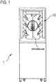
- the spindles of the first processing tool unit 40 and the second processing tool unit 45 are disposed to be tilted about an opposing axis across which the first processing unit 40 and the second processing unit 45 are opposed to each other(see Fig. 1 ).
- the spindles of the first processing tool unit 40 and the second processing tool unit 45 are symmetry with respect to the opposing axis.
- the spindles of the first processing tool unit 40 and the second processing tool unit 45 are disposed to be tilted in the downward direction (the direction of gravitational force).
- the tilt direction is not limited to this direction.
- the spindles may be tilted in the upward direction.
- At least two spindles may be disposed in at least one processing unit of the first processing tool unit 40 and the second processing tool unit 45.
- two or more spindles are arranged along the opposing axis of the first processing tool unit 40 and the second processing tool unit 45.
- plural spindles may be arranged in the Y-axis direction or may be arranged in the X-axis direction.
- Examples of the processing tool provided at each spindle include a drilling tool, a grooving tool, a processing tool for roughing (roughing tool), a processing tool for polishing (polishing tool), a finishing tool, and a processing tool for stepping. Other types of processing tools may be used.
- a processing tool for roughing is provided at the lowest spindle out of plural spindles of at least one of the first processing tool unit 40 and the second processing tool unit 45.
- a processing tool requiring a supply of water is provided at the lowest spindle out of plural spindles of at least one processing tool unit of the first processing tool unit 40 and the second processing tool unit 45.
- An example of the processing tool requiring a supply of water is a polishing tool.
- FIG. 1 is a diagram schematically illustrating the configuration of the apparatus body of the eyeglass lens processing apparatus according to the exemplary embodiment.
- a lens processing unit 10 that processes a lens is disposed in the upper part of the eyeglass lens processing apparatus 1.
- Fig. 2 is a diagram schematically illustrating the configuration of the lens processing unit 10. The configuration of the lens processing unit 10 will be described below.
- the lens processing unit 10 includes a lens chuck unit 20 and a spindle support unit 30.
- the lens chuck unit 20 serves to support an eyeglass lens LE and to move the eyeglass lens LE relative to the spindle support unit 30.
- the lens chuck unit 20 includes a carriage 21 and a base 24.
- the carriage 21 supports the lens chuck shafts 22L and 22R.
- the lens chuck shafts 22L and 22R are provided to chuck the eyeglass lens LE.
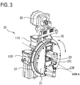
- Fig. 3 is a diagram schematically illustrating the configuration of the lens chuck unit 20.
- a chuck table 23 that can move on two guide rails (not shown) extending in the lateral direction is disposed on the rear surface of the carriage 21.
- the chuck table 23 is fixed to the lens chuck shaft 22L.
- the chuck table 23 is provided with a pressure-drive source (not shown) that moves the chuck table 23 in parallel to the lens chuck shaft.
- the pressure-drive source includes an air pump, a valve, and a piston.
- the air pump is used to pump air.
- the piston is fixed to the chuck table 23.
- the valve is disposed in an enclosed space in which the piston is disposed. Introduction of air into the enclosed space is adjusted by opening and shutting the valve.
- the pressure-drive source moves the piston in parallel to the lens chuck shaft by adjusting the introduction of air into the enclosed space. Accordingly, the lens chuck shaft 22L along with the chuck table 23 moves to the lens chuck shaft 22R fixed to the carriage 21 in parallel. The eyeglass lens LE is chucked by the lens chuck shaft 22L and the lens chuck shaft 22R fixed to the carriage 21.
- the lens chuck unit 20 is provided with a drive source (for example, a motor) 110.
- the motor 110 is used to rotate the lens chuck shaft 22L about the axis thereof.
- a rotation transmitting mechanism such as a timing belt or a pulley.
- the lens chuck unit 20 is provided with a drive source (for example, a motor) 120.
- the motor 120 is used to rotate the lens chuck shaft 22R about the axis thereof.
- the lens chuck shaft 22R is rotated by the motor 110 through the use of a rotation transmitting mechanism such as a timing belt or a pulley.
- Encoders for detecting the rotation angles of the lens chuck shafts 22L and 22R are mounted on the rotating shafts of the motors 110 and 120.
- the motors 110 and 120 are driven in synchronization with each other. That is, the lens chuck shafts 22L and 22R are rotationally driven in synchronization with each other.
- Fig. 4 is a diagram schematically illustrating the configuration of the lens chuck shaft 22.
- Fig. 4A shows a cross-sectional view of the lens chuck shaft 22.
- Fig. 4B shows an oblique projection view of the lens chuck shaft 22.
- Fig. 4C is a diagram illustrating the relationship between the lens chuck shaft 22 and a processing tool.
- the lens chuck shaft 22L and the spindle approach each other. At this time, when the diameter of the lens chuck shaft 22L is large, the lens chuck shaft 22L comes in contact with the spindle and thus the processable range of an eyeglass lens is restricted. Accordingly, in this example, the size of the lens chuck shaft 22L approaching the spindle is reduced and a cutout 11 is formed in the lens chuck shaft 22L.
- the lens chuck shaft 22L is formed to have a diameter smaller than that of the lens chuck shaft 22R. Accordingly, the diameter of a bearing 29L disposed in the lens chuck shaft 22L is also small.
- the bearing 29L is used to support the lens chuck shaft 22L so as to prevent the vibration of the lens chuck shaft 22L.
- the diameter of the bearing necessarily depends on the diameter of the lens chuck shaft. For example, when the diameter of the lens chuck shaft is large but the diameter of the bearing is not large, the lens chuck shaft is not stably supported. When the diameter of the bearing is small, the lens chuck shaft can be stably supported even by the bearing having a small diameter. That is, for the lens chuck shaft 22R having a diameter larger than that of the lens chuck shaft 22L, the diameter of the bearing 29R should be set to be larger than that of the bearing 29L.
- a cutout 11 is formed in the lens chuck shaft 22L.
- the lens chuck shaft 22L and the spindle 40a can get closer to each other due to the cutout 11 formed in the lens chuck shaft 22. That is, regarding a portion in which the lens chuck shaft comes in contact with the spindle when the lens chuck shaft and the spindle get close to each other, such a contact is avoided by removing a part of the lens chuck shaft.
- the lens chuck shaft 22 and the spindle can get closer to each other. Accordingly, it is possible to process an eyeglass lens up to a smaller diameter when processing the eyeglass lens.
- the diameter of the lens chuck shaft 22R out of the lens chuck shafts 22L and 22R constituting the lens chuck shaft 22 is set to be larger than that of the lens chuck shaft 22L. Accordingly, when an eyeglass lens is chucked and rotationally driven by the use of the lens chuck shafts 22L and 22R, it is possible to stably rotate the eyeglass. As the lens chuck shaft becomes larger, the driving force becomes larger and thus an eyeglass under the lens processing can be stably moved. Accordingly, by setting one lens chuck shaft 22R to be larger than the other lens chuck shaft 22L, a predetermined driving force can be secured at the time of processing of an eyeglass lens and thus the eyeglass lens can be stably moved.
- the lens chuck unit 20 is provided with a shaft angle changing mechanism (shaft angle changing means) 25.
- the shaft angle changing mechanism 25 is used to switch a processing tool or to adjust the relative position of an eyeglass lens and a processing tool at the time of processing of the eyeglass lens (details of which will be described later).
- the shaft angle changing mechanism 25 includes a driving source (for example, a motor) 26, a pulley 27, and a timing belt 28.
- the pulley 27 is fixed to the carriage 21.
- the motor 26 is rotationally driven, the rotation of the motor 26 is transmitted to the pulley 27 via the timing belt 28.
- the carriage 21 is rotationally driven with the central axis (A axis) of the carriage 21 as a rotation center relative to the base 24 by the rotation of the pulley 27.
- the shaft angle of the lens chuck shafts 22L and 22R are changed (rotated) about the A axis.
- the initial position of the carriage 21 at the time of starting the rotation is set to a position at which the axis direction of an eyeglass lens is parallel to the Y-axis direction when the eyeglass lens is chucked by the lens chuck shafts 22L and 22R (see S in Fig. 8A ).
- the lens chuck shafts 22L and 22R are located so that the lens chuck shaft 22L is located on the upper side and the lens chuck shaft 22R is located on the lower side. That is, the concave surface (rear surface) of the eyeglass lens is located on the upper side and the convex lens (front surface) of the eyeglass lens is located on the lower side.
- Fig. 5 is a diagram illustrating X-axis and Z-axis driving mechanisms of the lens chuck unit 20.
- the lens chuck unit 20 is provided with driving mechanisms (an X-axis driving mechanism 80 and a Z-axis driving mechanism 85) used to move the lens chuck unit 20 in the X direction and the Z direction relative to the spindle support unit 30, respectively.
- the X-axis driving mechanism 80 includes a driving source (motor) 81.
- the motor 81 is directly connected to a shaft 82 extending in the X-axis direction.
- the rotating shaft of the motor 81 is provided with an encoder for detecting the movement position in the X-axis direction of the lens chuck unit 20. Threads are formed on the outer peripheral portion of the shaft 82.
- a moving member for example, nut
- the lens chuck unit 20 is fixed to the moving member.
- the lens chuck unit 20 moves along the shaft 82 extending in the X-axis direction. Accordingly, the lens chuck shafts 22L and 22R move linearly in the X-axis direction along with the carriage 21.
- the Z-axis driving mechanism 85 includes a driving source (motor) 86.
- the motor 86 is directly connected to a shaft extending in the Z-axis direction.
- the rotating shaft of the motor 86 is provided with an encoder for detecting the movement position in the Z-axis direction of the lens chuck unit 20. Threads are formed on the outer peripheral portion of the shaft.
- a moving member for example, nut
- the lens chuck unit 20 is fixed to the moving member.
- the spindle support unit 30 includes a movement support base 31, a first processing tool unit 40 and a second processing tool unit 45 disposed on the left and right side surfaces thereof, and lens shape detecting units 50L and 50R.
- the first processing tool unit 40 and the second processing tool unit 45 are disposed on the left and right side surfaces of the movement support base 31.
- the first processing tool unit 40 is disposed on the left side surface of the movement support base 31 and includes three spindles (processing tool rotating shafts) 40a, 40b, and 40c.
- the second processing tool unit 45 is disposed on the right side surface of the movement support base 31 and includes three spindles 45a, 45b, and 45c.
- Processing tools 60a, 60b, and 60c are coaxially mounted on the spindles 40a, 40b, and 40c of the first processing tool unit 40, respectively.
- Processing tools 65a, 65b, and 65c are coaxially mounted on the spindles 45a, 45b, and 45c of the second processing tool unit 45, respectively.
- Each processing tool is used as a processing tool used for processing an eyeglass lens.
- the spindles are provided with hoses 41a, 41b, 41c, 46a, 46b, and 46c for supplying air or water, respectively.
- the hoses 41a, 41b, 41c, 46a, 46b, and 46c are used to remove chips generated through the processing of an eyeglass lens by the use of air.
- the hose 46a is used to supply water to be used for processing an eyeglass lens.
- the hose can be arbitrarily interchanged depending on its application. For example, a water hose may be interchanged with an air hose.
- Each spindle is disposed so as to tilt the tip of the spindle in the downward direction (the direction of gravitational force).
- the tilt angle of each spindle is set to 45° downward from the Z-axis direction (horizontal direction).
- the inter-tool width can be saved in comparison with a case where the spindles are arranged in the horizontal direction. Since the rotational driving in the shaft angle of the lens chuck shaft 22 can be reduced, it is possible to efficiently switch the first processing tool unit 40 and the second processing tool unit 45.
- the processing tools 60a, 60b, and 60c are coaxially mounted on the spindles 40a, 40b, and 40c of the first processing tool unit 40, respectively.
- the processing tools 65a, 65b, and 65c are coaxially mounted on the spindles 45a, 45b, and 45c of the second processing tool unit 45, respectively.
- the processing tools are used as processing tools for processing an eyeglass lens LE.
- the spindles are rotationally driven by a driving source (for example, a motor) mounted on the movement support base 31 via a rotation transmitting mechanism disposed in each spindle.
- a cutter as a roughing tool is provided at the processing tool 60a.
- the roughing tool is used to cut an eyeglass lens LE.
- a cutter as a processing tool for grooving (grooving tool) is provided at the processing tool 60b.
- An end mill as a processing tool for drilling (drilling tool) is provided at the processing tool 60c.
- a grindstone as a polishing tool is provided at the processing tool 65a.
- the polishing tool is used to polish an eyeglass lens LE into a specular surface using water.
- a cutter having a conical shape as a finishing tool is provided at the processing tool 65b.
- the finishing tool is used to perform beveling or chamfering.
- a processing tool for stepping is provided at the processing tool 65c.
- the roughing tool and the polishing tool are disposed in the lowest spindles 60a and 65a of the first processing tool unit 40 and the second processing tool unit 45, respectively. Accordingly, it is possible to easily suppress a reason for deteriorating the driving of other processing tools (spindles) or a reason of breakdown thereof. That is, chips or water generated at the time of processing of an eyeglass lens does not have an influence on other processing tools. Particularly, when the processing tool for roughing generates large chips due to the cutting of a lens in a predetermined shape and causes a large influence on other processing tools due to attachment of the chips to other processing tools is used, this configuration is useful. When the processing tool for polishing requiring water is used, this configuration is also useful.
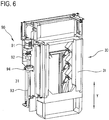
- Fig. 6 is a diagram illustrating the Y-axis driving mechanism of the spindle support unit 30.
- the spindle support unit 30 is provided with a driving mechanism (Y-axis driving mechanism 90) for causing the spindle support unit 30 to move in the Y-axis direction relative to the lens chuck unit 20.
- a driving mechanism Y-axis driving mechanism 90
- the Y-axis driving mechanism 90 includes a driving source (motor) 91.
- the rotating shaft of the motor 91 is directly connected to a shaft 92 extending in the Y-axis direction.
- the motor 91 is provided with an encoder for detecting the movement position in the Y-axis direction of the spindle support unit 30. Threads are formed on the outer peripheral surface of the shaft.
- a moving member (for example, a nut) 94 as a bearing is fitted to an end of the shaft.
- the movement support base 31 is fixed to the moving member 94.
- the motor 91 is rotationally driven, the movement support base 31 moves along the shaft extending in the Y-axis direction. Accordingly, the spindle support unit 30 moves linearly in the Y-axis direction.
- a spring (not shown) is hooked on the movement support base 31 and serves to cancel the downward load of the movement support base 31 to facilitate the movement.
- lens shape detecting units (lens edge shape detecting units) 50L and 50R and a driving mechanism 55 of the lens shape detecting units are disposed above the carriage 21.
- the lens shape detecting unit 50L detects the position of the front lens surface (the front lens position of a target lens shape).
- the lens shape detecting unit 50R detects the position of the rear lens surface (the rear lens position of a target lens shape).
- Tracing styluses 51F and 51R are fixed to the tips of the lens shape detecting units 50L and 50R.
- the tracing stylus 51F comes in contact with the front surface of an eyeglass lens LE.
- the tracing stylus 51R comes in contact with the rear surface the eyeglass lens LE.
- the lens shape detecting units 50L and 50R are supported to be slidable in the Z-axis direction.
- the driving mechanism 55 is used to cause the lens shape detecting units 50L and 50R to move in the Z-axis direction.
- the rotation driving of a motor (not shown) in the driving mechanism 55 is transmitted to the lens shape detecting units 50L and 50R via a rotation transmitting mechanism such as a gear.
- the tracing styluses 51R and 51R located at the evacuated position moves to the eyeglass lens LE, and a measuring pressure for pressing the tracing styluses 51F and 51R against the eyeglass lens LE.
- the configuration for pressing the tracing styluses 51F and 51R is not limited to this configuration.
- a configuration in which the tracing styluses 51F and 51R are pressed using a spring can be used.
- the spindle support unit 30 When detecting the front surface position of the eyeglass lens LE, the spindle support unit 30 is made to move in the Y-axis direction while rotating the eyeglass lens LE on the basis of the target lens shape, and the position (the position of the front lens surface on the target lens shape) in the X-axis direction of the front lens surface is detected by an encoder (not shown). Regarding the rear lens surface, the position of the rear surface is detected in the same way as detecting the position of the front lens surface.
- Fig. 7 is a control block diagram of the eyeglass lens processing apparatus.
- the motor 26, the motor 110, the motor 120, the motor 81, the motor 86, the motor 91, a motor (not shown) installed in each spindle, a pressure driving source (not shown), and the lens shape detecting units 50L and 50R are connected to the controller 70.
- a display 5 having a touch panel function for inputting processing condition data, a switch unit 7 provided with a processing start switch and the like, a memory 3, a host computer, and the like are connected to the controller 70.
- the control operation of the eyeglass lens processing apparatus 1 in this example will be described below.
- the processing of an eyeglass lens is performed by selecting various processing steps depending on the processing condition data such as a target lens shape input from the host computer.
- a roughing process and a finishing process will be exemplified as various processing steps.
- an eyeglass lens is conveyed to the eyeglass lens processing apparatus 1 by a conveyer system (not shown).
- the conveyer system causes the lens chuck shafts 22L and 22R to chuck the eyeglass lens.
- the controller 70 starts processing the eyeglass lens in the processing steps on the basis of previously-input lens data of the target lens shape.
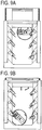
- Figs. 8A to 8C are diagrams illustrating the driving operation of the eyeglass lens processing apparatus 1 at the time of processing an eyeglass lens.
- Fig. 8A is a diagram illustrating the positional relationship (initial position) of the eyeglass lens processing apparatus 1 before and after starting the processing when setting or taking out an eyeglass lens.
- S solid line
- the initial position in the Y-axis direction is the highest position of the driving range in the Y-axis direction.
- the initial position in the Z-axis direction is the middle position of the driving range in the Z-axis direction.
- the initial position in the X-axis direction is the forefront position of the driving range in the X-axis direction.
- the initial position is not limited to the above-mentioned position.
- the initial position only has to be in the driving range of the eyeglass lens processing apparatus 1.
- An examiner may arbitrarily set the initial position.
- the positions of the front lens surface and the rear lens surface are detected by the lens shape detecting units 50L and 50R to acquire lens shape data.
- the controller 70 drives the motor 81 to cause the lens chuck unit 20 to retreat in the X-axis direction. Subsequently, the controller 70 drives the motor 91 to cause the spindle support unit 30 to move in the Y-axis direction (see Fig. 8B ). At the time of movement in the Y-axis direction, the controller 70 drives the motor 26 to cause the carriage 21 to rotate about the A axis and to change the shaft angle of the lens chuck shaft 22. For example, as shown in Fig.
- the controller 70 causes the lens chuck shaft 22 to rotate about the A axis by a predetermined angle in the direction (counterclockwise direction) from the initial position S.
- the lens chuck shaft may be made to rotate by a predetermined angle in the b direction (clockwise direction).
- the controller 70 drives the motor 86 to cause the lens chuck shaft to move in the Z-axis direction (see Fig. 8D ).
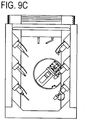
- Figs. 9A to 9C are diagrams illustrating the position adjustment in the Y-axis and Z-axis direction and the positional relationship of the lens chuck shaft 22 after adjustment.
- the controller 70 adjusts the positions in the Y-axis and Z-axis directions and the shaft angle of the lens chuck shaft 22 so that the eyeglass lens LE is located at the positions of the lens shape detecting units 50L and 50R (see Fig. 9A ).
- the controller 70 rotates (changes) the shaft angle of the lens chuck shaft 22 by 270° in the a direction (90° in the b direction) from the initial position S.
- the controller 70 After adjusting the positions in the Y-axis and the Z-axis directions and the shaft angle of the lens chuck shaft 22, the controller 70 drives the motor 81 to cause the lens chuck unit 20 to go ahead in the X-axis direction. In this way, when the eyeglass lens LE is located at the positions of the lens shape detecting units 50L and 50R, the controller 70 controls the rotational driving and the driving in the Y-axis direction of the lens chuck shaft 22 to acquire lens shape data.
- the controller 70 performs processing of the eyeglass lens LE by the use of the processing tools.
- the lens chuck shaft 22 is made to rotate by a predetermined angle so that the front lens surface face the bases of the processing tools.
- the controller 70 drives the motor 81 to cause the lens chuck unit 20 to retreat in the X-axis direction.
- the controller 70 adjusts the positions in the Y-axis and Z-axis directions and the shaft angle of the lens chuck shaft 22 so that the eyeglass lens LE is located at the position of the processing tool 60a for roughing (see Fig. 9B ).
- the controller 70 changes the shaft angle of the lens chuck shaft 22 about the A axis by 45° in the b direction from the shaft angle when the lens shape data is acquired.
- the changing of the shaft angle is not limited to this description.
- the shaft angle has only to be changed so that the eyeglass lens LE is located at the position of the processing tool 60a for roughing.
- the lens chuck shaft 22 may be first returned to the initial position S and then may be rotated by 225° in the a direction.
- the controller 70 tilts the lens chuck shaft 22 so that the lens chuck shaft 22 is parallel to the spindle 45a, and controls the driving in the Y-axis direction and the Z-axis direction on the basis of the target lens shape.
- the lens chuck shaft 22 is tilted so as for the spindle 45a to be parallel to the normal direction of the front curve of the eyeglass lens LE, and the driving in the Y-axis direction and the Z-axis direction is controlled on the basis of the target lens shape so that the eyeglass lens is located within the processing range of the roughing tool 60a.
- the lens chuck shaft 22 is tilted so that the lens chuck shaft 22 is parallel to the spindle 40a, and the driving in the Y-axis direction and the Z-axis direction is controlled on the basis of the target lens shape.
- the controller 70 drives the driving source (not shown) and drives the spindle 40a to cause the processing tools to rotate coaxially.
- the controller 70 controls the driving in the Y-axis direction and the Z-axis direction on the basis of the target lens shape to perform the roughing process.
- the controller 70 performs a finishing process.
- the controller 70 drives the motor 81 to cause the lens chuck unit 20 to retreat in the X-axis direction.
- the controller 70 adjusts the positions in the Y-axis and Z-axis directions and the shaft angle of the lens chuck shaft 22 so that the eyeglass lens LE is located at the position of the processing tool 65b for finishing (see Fig. 9C ).
- the controller 70 changes the shaft angle of the lens chuck shaft 22 about the A axis by 90° in the b direction from the shaft angle for the roughing process.
- the changing of the shaft angle may be performed by first returning the lens chuck shaft to the initial position S and then causing the lens chuck shaft 22 to rotate by 135° in the a direction. That is, the controller 70 can switch the processing tools to be used for the processing by changing the shaft angle of the lens chuck shaft about the A axis.
- the controller 70 sets the lens chuck shaft 22 to be parallel to the conical processing surface of the processing tool 65b. Alternatively, when an edge has a tapered shape (the end becomes thinner), the controller 70 may tilt the lens chuck shaft 22 so as to be oblique about the conical processing surface depending on the taper angle. Then, the finishing process is performed.
- the controller 70 controls the driving in the Y-axis direction and the Z-axis direction to locate a predetermined position of an edge after the roughing process at a beveling groove of the processing tool 65b on the basis of the bevel path (which is obtained through a predetermined calculating operation based on the edge thickness of the eyeglass lens).
- the controller 70 changes the shaft angle of the lens chuck shaft 22 about the A axis along the lens curve or the bevel curve, and controls the rotational driving of the shaft angle of the lens chuck shaft 22 to locate a predetermined position of the edge after the roughing process at the bevel groove of the processing tool 65b.
- the controller 70 controls the driving in the Y-axis direction and the Z-axis direction on the basis of the target lens shape so that the edge after the roughing process is located on the flat-finishing surface of the processing tool.
- the controller 70 changes the shaft angle of the lens chuck shaft 22 about the A axis so to be oblique about the conical processing surface by a predetermined angle or to be perpendicular to the front curve of the eyeglass lens LE, and controls the rotational driving of the shaft angle of the lens chuck shaft 22.
- the controller 70 drives the driving source (not shown) to rotationally drive the spindle 45b and to cause the processing tools to rotate coaxially therewith.
- the controller 70 controls the driving in the Y-axis direction and the Z-axis direction and the driving of the shaft angle of the lens chuck shaft 22 on the basis of the target lens shape to perform the finishing process.
- the processing tool 65b is also used as a processing tool for chamfering.
- the flat-finishing surface is also used as a chamfering surface.
- the controller 70 controls the tilt angle of the lens chuck shaft 22 on the basis of the chamfering angle. That is, the controller 70 performs a chamfering process by controlling the driving in the Y-axis direction and the Z-axis direction on the basis of the chamfering path (which is obtained through a predetermined calculating operation based on the position of the front lens surface (front edge) and the position of the rear lens surface (rear edge)).
- the controller 70 changes the shaft angle of the lens chuck shaft 22 by 180° in the a direction or the b direction to switch the front surface and the rear surface of the eyeglass lens to be processed by the processing tool 65b. In this way, by changing the shaft angle of the lens chuck shaft 22, it is possible to perform the chamfering process on the front surface and the rear surface of the eyeglass lens through the use of a single processing tool.
- the controller 70 performs a polishing process.
- the controller 70 drives the motor 81 to cause the lens chuck unit 20 to retreat in the X-axis direction.
- the controller 70 adjusts the positions in the Y-axis direction and the Z-axis direction and the shaft angle of the lens chuck shaft 22 in the same way as performed in the roughing and finishing processes, so that the eyeglass lens LE is located at the position of the processing tool 65a for polishing.
- the polishing process is performed under the same control as described above in the finishing process.
- the controller 70 drives the driving source (not shown) to rotationally drive the spindle 45b and to cause the processing tools to rotate coaxially therewith. Then, the controller 70 controls the driving in the Y-axis direction and the Z-axis direction and the shaft angle of the lens chuck shaft 22 on the basis of the target lens shape to perform the polishing process. Water is used to perform the polishing process.
- the positions in the Y-axis direction and the Z-axis direction and the shaft angle of the lens chuck shaft 22 are adjusted so as to locate the eyeglass lens LE at the positions of the processing tools, in the same way as described above.
- the controller 70 performs the flat-finishing process using the processing tool 60b and then controls the driving in the Y-axis direction and the Z-axis direction on the basis of the groove path (which is obtained through a predetermined calculating operation based on the edge thickness of the eyeglass lens) to perform the grooving process.
- the controller 70 causes the front lens surface to face the tip of the processing tool 60c.
- the controller 70 tilts the lens chuck shaft so as for the shaft of the drilling tool to be parallel to the normal direction at the drilling position on the basis of input drilling position data and a front lens surface shape (which is obtained through lens shape measurement) at the drilling position, and controls the driving in the Y-axis direction and the Z-axis direction to perform the drilling process.
- the controller 70 tilts the lens chuck shaft 22 on the basis of the tilt of the processing tool 65c. Then, the controller 70 controls the driving in the Y-axis direction and the Z-axis direction to perform the stepping process on the basis of the bevel path and an input stepping path (the positional path of the corners of an L shape).
- the lens chuck shaft 22 is made to retreat once in the X-axis direction and then the driving in the Y-axis direction and the Z-axis direction and the shaft angle of the lens chuck shaft 22 are adjusted. Accordingly, it is possible to perform the adjustment in the shortest distance, thereby reducing the necessary time.
- the lens chuck shaft 22 By causing the lens chuck shaft 22 to retreat and then performing the adjustment, it is possible to prevent interference (contact) of the lens chuck shaft 22 with the processing tools and the like, thereby preventing destruction of breakdown of the apparatus.
- the control operation for processing is not limited to the above-mentioned sequence.
- the roughing process may be first performed, then the lens shape data may be acquired, and the finishing process may be performed.
- the controller 70 causes the lens chuck shaft 22 to rotate by 225° in the a direction from the initial position S and performs the roughing process. Thereafter, the controller 70 causes the lens chuck shaft to rotate by 45° in the a direction so as to make the lens chuck shaft horizontal and acquires the lens shape data through the use of the lens shape detecting units 50L and 50R. After acquiring the lens shape data, the controller 70 causes the lens chuck shaft to rotate by 45° in the b direction and to perform the finishing process.
- An examiner may arbitrarily change the sequence of the control operation.
- the driving operations of changing the shaft angel of the lens chuck shaft 22 may not be continuously performed, but the lens chuck shaft may be returned to the initial position S for each step (processing or detecting) and then the shaft angle may be changed.
- the lens chuck shaft 22 is rotationally driven in the shaft angle and is driven in the Z-axis direction and the X-axis direction. That is, the lens chuck shaft 22 does not move in the Y-axis direction in which the movement is large. Accordingly, the eyeglass lens chucked by the lens chuck shaft 22 hardly moves from the initial position. For example, when an inlet and an outlet of an eyeglass lens are disposed at the initial position, the time until the eyeglass lens is returned to the initial position after the processing process is completed is shortened. Accordingly, it is possible to easily interchange an eyeglass lens and thus to improve the processing efficiency of an eyeglass lens.
Claims (7)
- Brillenglas-Bearbeitungseinrichtung zum Bearbeiten eines Umfangs eines Brillenglases, wobei die Brillenglas-Bearbeitungseinrichtung umfasst:eine Brillenglas-Spannfutterwelle (22), die das Brillenglas unter Verwendung eines Paars einer ersten Brillenglas-Spannfutterwelle (22L) und einer zweiten Brillenglas-Spannfutterwelle (22R) einspannt;eine erste Bearbeitungswerkzeugeinheit (40) zum Bearbeiten eines Umfangs des Brillenglases, die zumindest eine Spindel umfasst, an der ein erstes Bearbeitungswerkzeug vorgesehen ist; undeine zweite Bearbeitungswerkzeugeinheit (45) zum Bearbeiten eines Umfangs des Brillenglases, die gegenüber der ersten Bearbeitungswerkzeugeinheit angeordnet ist und die zumindest eine Spindel umfasst, an der ein zweites Bearbeitungswerkzeugs vorgesehen ist; undgekennzeichnet durch:eine Wellenwinkel-Änderungseinrichtung (24) zum Ändern eines Wellenwinkels der Brillenglas-Spannfutterwelle (22); undeine Steuereinrichtung (70), die zum Wechseln einer der ersten und zweiten Bearbeitungswerkzeugeinheit, die zum Bearbeiten des Brillenglases verwendet wird, auf die jeweils andere der ersten und zweiten Bearbeitungswerkzeugeinheit durch Steuern eines Antriebs der Wellenwinkel-Änderungseinrichtung zum Ändern des Wellenwinkels der Brillenglas-Spannfutterwelle,wobei die Spindeln der ersten und zweiten Bearbeitungswerkzeugeinheiten (40, 45) in Bezug auf eine gegenüberliegende Achse symmetrisch sind.
- Brillenglas-Bearbeitungseinrichtung nach Anspruch 1, wobei die Steuereinrichtung (70) einen vorgegebenen Bearbeitungsprozess durch Einstellen eines Neigungswinkels der Brillenglas-Spannfutterwelle (22) in Bezug auf die erste Bearbeitungswerkzeugeinheit (40) und die zweite Bearbeitungswerkzeugeinheit (45) beim Bearbeiten des Brillenglases unter Verwendung der Wellenwinkel-Änderungseinrichtung (25) ausführt.
- Brillenglas-Bearbeitungseinrichtung nach Anspruch 1 oder 2, wobei die Wellenwinkel-Änderungseinrichtung (24) eine Drehbasis (21) aufweist, welche die Brillenglas-Spannfutterwelle (22) zum Ändern des Wellenwinkels der Brillenglas-Spannfutterwelle abstützt und die Drehbasis (21) um eine Mittelachse (A) der Drehbasis senkrecht zur Brillenglas-Spannfutterwelle dreht.
- Brillenglas-Bearbeitungseinrichtung nach einem der Ansprüche 1 bis 3, wobei
die Spindeln der ersten und zweiten Bearbeitungswerkzeugeinheiten (40, 45) einander über eine gegenüberliegende Achse (Y) gegenüberliegen, und
die Spindeln der ersten und zweiten Bearbeitungswerkzeugeinheiten (40, 45) um die gegenüberliegende Achse geneigt sind. - Brillenglas-Bearbeitungseinrichtung nach einem der Ansprüche 1 bis 4, wobei zumindest eine der ersten und zweiten
Bearbeitungswerkzeugeinheiten (40, 45) eine Vielzahl von Spindeln umfasst. - Brillenglas-Bearbeitungseinrichtung nach einem der Ansprüche 1 bis 5, wobei
zumindest eine der ersten und zweiten Bearbeitungswerkzeugeinheiten (40, 45) mindestens zwei Spindeln umfasst,
die mindestens zwei Spindeln der zumindest einen der ersten und zweiten Bearbeitungswerkzeugeinheiten (40, 45) in vertikaler Richtung der Brillenglas-Bearbeitungseinrichtung angeordnet sind,
die Spindel, die aus den mindestens zwei Spindeln der zumindest einen der ersten und zweiten Bearbeitungswerkzeugeinheiten (40, 45) an einer untersten Position angeordnet ist, mit einem Bearbeitungswerkzeug (60a) zum Schruppen versehen ist. - Brillenglas-Bearbeitungseinrichtung nach einem der Ansprüche 1 bis 5, wobei
zumindest eine der ersten und zweiten Bearbeitungswerkzeugeinheiten (40, 45) mindestens zwei Spindel umfasst,
die mindestens zwei Spindeln der zumindest einen der ersten und zweiten Bearbeitungswerkzeugeinheiten in vertikaler Richtung der Brillenglas-Bearbeitungseinrichtung angeordnet sind,
die Spindel, die aus den mindestens zwei Spindeln der zumindest einen der ersten und zweiten Bearbeitungswerkzeugeinheiten an einer untersten Position angeordnet ist, mit einem Bearbeitungswerkzeug (65a) versehen ist, das eine Wasserzufuhr erfordert.
Applications Claiming Priority (1)
| Application Number | Priority Date | Filing Date | Title |
|---|---|---|---|
| JP2012052964A JP5935407B2 (ja) | 2012-03-09 | 2012-03-09 | 眼鏡レンズ加工装置 |
Publications (3)
| Publication Number | Publication Date |
|---|---|
| EP2636484A2 EP2636484A2 (de) | 2013-09-11 |
| EP2636484A3 EP2636484A3 (de) | 2014-11-12 |
| EP2636484B1 true EP2636484B1 (de) | 2018-05-30 |
Family
ID=47845696
Family Applications (1)
| Application Number | Title | Priority Date | Filing Date |
|---|---|---|---|
| EP13001157.0A Active EP2636484B1 (de) | 2012-03-09 | 2013-03-08 | Vorrichtung zum Bearbeiten von Brillengläsern |
Country Status (4)
| Country | Link |
|---|---|
| US (1) | US9776293B2 (de) |
| EP (1) | EP2636484B1 (de) |
| JP (1) | JP5935407B2 (de) |
| CN (1) | CN103302567B (de) |
Families Citing this family (12)
| Publication number | Priority date | Publication date | Assignee | Title |
|---|---|---|---|---|
| JP5899978B2 (ja) * | 2012-02-03 | 2016-04-06 | 株式会社ニデック | 眼鏡レンズ加工装置 |
| JP6197406B2 (ja) | 2013-06-28 | 2017-09-20 | 株式会社ニデック | 眼鏡レンズ加工装置、眼鏡レンズ加工プログラム |
| DE102014015053A1 (de) * | 2014-10-15 | 2016-04-21 | Satisloh Ag | Vorrichtung zur Feinbearbeitung von optisch wirksamen Flächen an insbesondere Brillengläsern |
| CN104391383B (zh) * | 2014-10-20 | 2016-02-03 | 四川仁心医疗科技有限公司 | 一种镜片加工参照点标示设备 |
| CN104267509B (zh) * | 2014-10-20 | 2016-01-20 | 四川仁心医疗科技有限公司 | 一种有利于提高镜片成形质量的加工设备 |
| CN106002535B (zh) * | 2015-03-31 | 2020-05-22 | 尼德克株式会社 | 眼镜镜片加工装置 |
| JP6766400B2 (ja) * | 2016-03-28 | 2020-10-14 | 株式会社ニデック | 眼鏡レンズ加工装置、及び眼鏡レンズ加工プログラム |
| CN109702249B (zh) * | 2017-10-26 | 2020-11-03 | 富鼎电子科技(嘉善)有限公司 | 双五轴加工装置 |
| CN108115475A (zh) * | 2017-12-21 | 2018-06-05 | 合肥仨力机械制造有限公司 | 一种轮辋外周面连续打磨设备 |
| EP3517284A1 (de) * | 2018-01-26 | 2019-07-31 | Essilor International | System und verfahren zur automatisierten herstellung von brillengläsern |
| DE102018007463B4 (de) * | 2018-09-04 | 2022-01-05 | Schneider Gmbh & Co. Kg | Vorrichtung und Verfahren zur Linsenbearbeitung sowie Bearbeitungseinrichtung für Linsen |
| USD952158S1 (en) * | 2019-04-26 | 2022-05-17 | Lambda-X S.A. | Instrument for measuring, controlling, and testing optical lenses |
Family Cites Families (23)
| Publication number | Priority date | Publication date | Assignee | Title |
|---|---|---|---|---|
| US2493206A (en) * | 1945-06-27 | 1950-01-03 | Perry Lowell & Co | Lens grinding and polishing machine |
| DE3025638C2 (de) * | 1980-07-07 | 1982-08-12 | Fa. Gottlieb Gühring, 7470 Ebingen | Rundschalttisch-Maschine |
| JPS6299065A (ja) * | 1985-10-22 | 1987-05-08 | Matsushita Electric Ind Co Ltd | 球面研削装置 |
| DE19504368A1 (de) | 1995-02-10 | 1996-08-14 | Index Werke Kg Hahn & Tessky | Werkzeugmaschine |
| US6298531B1 (en) * | 1997-06-17 | 2001-10-09 | Witzig & Frank Gmbh | Highly flexible machine tool |
| JP4002324B2 (ja) | 1997-07-08 | 2007-10-31 | 株式会社ニデック | レンズ研削装置 |
| DE19751750B4 (de) | 1997-11-21 | 2007-08-02 | Schneider Gmbh + Co. Kg | Verfahren und Vorrichtung zum Herstellen von polierbaren, optischen Linsen aus Linsenrohlingen |
| JP2000218487A (ja) | 1999-02-01 | 2000-08-08 | Topcon Corp | レンズ研削加工装置 |
| DE10029967B4 (de) * | 2000-06-26 | 2006-08-03 | Satisloh Gmbh | Vorrichtung zur Bearbeitung von optischen Werkstücken |
| JP2003300158A (ja) | 2002-04-08 | 2003-10-21 | Hoya Corp | レンズ加工装置 |
| JP4131842B2 (ja) * | 2003-08-29 | 2008-08-13 | 株式会社ニデック | 眼鏡レンズ加工装置 |
| JP4873878B2 (ja) | 2005-03-31 | 2012-02-08 | 株式会社ニデック | 眼鏡レンズ周縁加工装置 |
| JP4290672B2 (ja) * | 2005-04-28 | 2009-07-08 | 株式会社ニデック | 眼鏡レンズ周縁加工装置 |
| JP4446934B2 (ja) * | 2005-06-30 | 2010-04-07 | 株式会社ニデック | 眼鏡レンズ加工装置 |
| JP2007152439A (ja) * | 2005-11-30 | 2007-06-21 | Nidek Co Ltd | 眼鏡レンズ加工装置 |
| FR2906746B1 (fr) * | 2006-10-10 | 2009-05-22 | Essilor Int | Dispositif d'usinage de lentilles ophtalmiques comprenant une pluralite d'outils d'usinage disposes sur un module orientable |
| DE102007031703A1 (de) | 2007-07-06 | 2009-01-08 | Satisloh Gmbh | Maschine zur Bearbeitung von optischen Werkstücken, insbesondere von Kunststoff-Brillengläsern |
| JP5057881B2 (ja) * | 2007-08-03 | 2012-10-24 | 株式会社ニデック | 眼鏡レンズ周縁加工装置 |
| JP5134346B2 (ja) * | 2007-11-30 | 2013-01-30 | 株式会社ニデック | 眼鏡レンズ周縁加工装置 |
| DE102008004172B4 (de) * | 2008-01-11 | 2016-04-14 | Schneider Gmbh & Co. Kg | Bearbeitungsmaschine |
| JP5331464B2 (ja) * | 2008-11-28 | 2013-10-30 | 株式会社ニデック | 眼鏡レンズ加工装置及び眼鏡レンズ加工方法 |
| JP6187742B2 (ja) * | 2013-03-29 | 2017-08-30 | 株式会社ニデック | 眼鏡レンズ加工装置 |
| JP6197406B2 (ja) * | 2013-06-28 | 2017-09-20 | 株式会社ニデック | 眼鏡レンズ加工装置、眼鏡レンズ加工プログラム |
-
2012
- 2012-03-09 JP JP2012052964A patent/JP5935407B2/ja active Active
-
2013
- 2013-03-07 US US13/788,622 patent/US9776293B2/en active Active
- 2013-03-08 EP EP13001157.0A patent/EP2636484B1/de active Active
- 2013-03-08 CN CN201310074707.2A patent/CN103302567B/zh active Active
Non-Patent Citations (1)
| Title |
|---|
| None * |
Also Published As
| Publication number | Publication date |
|---|---|
| US20130232774A1 (en) | 2013-09-12 |
| EP2636484A2 (de) | 2013-09-11 |
| JP2013184270A (ja) | 2013-09-19 |
| EP2636484A3 (de) | 2014-11-12 |
| CN103302567A (zh) | 2013-09-18 |
| US9776293B2 (en) | 2017-10-03 |
| JP5935407B2 (ja) | 2016-06-15 |
| CN103302567B (zh) | 2017-08-29 |
Similar Documents
| Publication | Publication Date | Title |
|---|---|---|
| EP2636484B1 (de) | Vorrichtung zum Bearbeiten von Brillengläsern | |
| KR100996876B1 (ko) | 네크부 연삭장치와 네크부 연삭장치에 사용되는 연삭장치 | |
| JP4456520B2 (ja) | 多軸球面研削装置及び研削方法 | |
| KR200483921Y1 (ko) | 경질 취성판의 둘레가장자리 가공장치 | |
| JP2013123770A (ja) | 加工装置 | |
| JP2009072879A (ja) | 端面研削方法および両面研削装置 | |
| CN105538052A (zh) | 旋转切削工具磨削及夹持装置 | |
| CN102452030A (zh) | 磨削方法、磨削系统以及多功能磨削机床 | |
| JP2009095911A (ja) | 旋回装置およびそれを備えた円筒研削盤 | |
| JP6051698B2 (ja) | 眼鏡レンズ加工装置 | |
| JP4712586B2 (ja) | Nc工作機械 | |
| JP2006297511A (ja) | レンズの球面研削方法 | |
| JP2006297512A (ja) | レンズの球面加工装置 | |
| JP2001088000A (ja) | レンズ加工方法 | |
| JP6051699B2 (ja) | 眼鏡レンズ加工装置 | |
| JP6244788B2 (ja) | 眼鏡レンズ加工装置 | |
| JP2018015891A (ja) | 加工装置、その制御方法、及びプログラム | |
| JP2009090390A (ja) | 工作物外径面および平面のセンタレス研削方法およびセンタレス研削装置 | |
| JP6135288B2 (ja) | 研削盤 | |
| JP6135287B2 (ja) | 研削盤 | |
| JP2016221641A (ja) | 切削装置及び切削方法 | |
| JP2010089225A (ja) | カム面の研削方法 | |
| KR20140089048A (ko) | 절삭가공기구 및 절삭가공방법 | |
| KR101236996B1 (ko) | 수직형 연삭기 | |
| JP3969905B2 (ja) | レンズ加工方法 |
Legal Events
| Date | Code | Title | Description |
|---|---|---|---|
| PUAI | Public reference made under article 153(3) epc to a published international application that has entered the european phase |
Free format text: ORIGINAL CODE: 0009012 |
|
| AK | Designated contracting states |
Kind code of ref document: A2 Designated state(s): AL AT BE BG CH CY CZ DE DK EE ES FI FR GB GR HR HU IE IS IT LI LT LU LV MC MK MT NL NO PL PT RO RS SE SI SK SM TR |
|
| AX | Request for extension of the european patent |
Extension state: BA ME |
|
| PUAL | Search report despatched |
Free format text: ORIGINAL CODE: 0009013 |
|
| AK | Designated contracting states |
Kind code of ref document: A3 Designated state(s): AL AT BE BG CH CY CZ DE DK EE ES FI FR GB GR HR HU IE IS IT LI LT LU LV MC MK MT NL NO PL PT RO RS SE SI SK SM TR |
|
| AX | Request for extension of the european patent |
Extension state: BA ME |
|
| RIC1 | Information provided on ipc code assigned before grant |
Ipc: B24B 47/22 20060101ALI20141007BHEP Ipc: B24B 13/00 20060101ALI20141007BHEP Ipc: B23Q 1/64 20060101ALI20141007BHEP Ipc: B24B 27/00 20060101AFI20141007BHEP Ipc: B24B 9/14 20060101ALI20141007BHEP Ipc: B23Q 15/26 20060101ALI20141007BHEP |
|
| 17P | Request for examination filed |
Effective date: 20150512 |
|
| RBV | Designated contracting states (corrected) |
Designated state(s): AL AT BE BG CH CY CZ DE DK EE ES FI FR GB GR HR HU IE IS IT LI LT LU LV MC MK MT NL NO PL PT RO RS SE SI SK SM TR |
|
| 17Q | First examination report despatched |
Effective date: 20151016 |
|
| STAA | Information on the status of an ep patent application or granted ep patent |
Free format text: STATUS: EXAMINATION IS IN PROGRESS |
|
| REG | Reference to a national code |
Ref country code: DE Ref legal event code: R079 Ref document number: 602013037993 Country of ref document: DE Free format text: PREVIOUS MAIN CLASS: B24B0027000000 Ipc: B24B0041000000 |
|
| GRAP | Despatch of communication of intention to grant a patent |
Free format text: ORIGINAL CODE: EPIDOSNIGR1 |
|
| STAA | Information on the status of an ep patent application or granted ep patent |
Free format text: STATUS: GRANT OF PATENT IS INTENDED |
|
| RIC1 | Information provided on ipc code assigned before grant |
Ipc: B23Q 1/64 20060101ALI20171117BHEP Ipc: B23Q 39/02 20060101ALI20171117BHEP Ipc: G05B 19/4093 20060101ALI20171117BHEP Ipc: B23Q 11/10 20060101ALI20171117BHEP Ipc: B24B 41/00 20060101AFI20171117BHEP Ipc: B24B 9/14 20060101ALI20171117BHEP Ipc: B28D 1/14 20060101ALI20171117BHEP Ipc: B23Q 17/20 20060101ALI20171117BHEP Ipc: B23Q 1/48 20060101ALI20171117BHEP Ipc: G05B 19/401 20060101ALI20171117BHEP Ipc: B24B 27/00 20060101ALI20171117BHEP Ipc: B23Q 11/00 20060101ALI20171117BHEP Ipc: B23Q 39/00 20060101ALI20171117BHEP |
|
| INTG | Intention to grant announced |
Effective date: 20171208 |
|
| GRAS | Grant fee paid |
Free format text: ORIGINAL CODE: EPIDOSNIGR3 |
|
| GRAA | (expected) grant |
Free format text: ORIGINAL CODE: 0009210 |
|
| STAA | Information on the status of an ep patent application or granted ep patent |
Free format text: STATUS: THE PATENT HAS BEEN GRANTED |
|
| AK | Designated contracting states |
Kind code of ref document: B1 Designated state(s): AL AT BE BG CH CY CZ DE DK EE ES FI FR GB GR HR HU IE IS IT LI LT LU LV MC MK MT NL NO PL PT RO RS SE SI SK SM TR |
|
| REG | Reference to a national code |
Ref country code: GB Ref legal event code: FG4D |
|
| REG | Reference to a national code |
Ref country code: CH Ref legal event code: EP |
|
| REG | Reference to a national code |
Ref country code: AT Ref legal event code: REF Ref document number: 1003128 Country of ref document: AT Kind code of ref document: T Effective date: 20180615 |
|
| REG | Reference to a national code |
Ref country code: DE Ref legal event code: R096 Ref document number: 602013037993 Country of ref document: DE |
|
| REG | Reference to a national code |
Ref country code: IE Ref legal event code: FG4D |
|
| REG | Reference to a national code |
Ref country code: NL Ref legal event code: MP Effective date: 20180530 |
|
| REG | Reference to a national code |
Ref country code: LT Ref legal event code: MG4D |
|
| PG25 | Lapsed in a contracting state [announced via postgrant information from national office to epo] |
Ref country code: NO Free format text: LAPSE BECAUSE OF FAILURE TO SUBMIT A TRANSLATION OF THE DESCRIPTION OR TO PAY THE FEE WITHIN THE PRESCRIBED TIME-LIMIT Effective date: 20180830 Ref country code: CY Free format text: LAPSE BECAUSE OF FAILURE TO SUBMIT A TRANSLATION OF THE DESCRIPTION OR TO PAY THE FEE WITHIN THE PRESCRIBED TIME-LIMIT Effective date: 20180530 Ref country code: LT Free format text: LAPSE BECAUSE OF FAILURE TO SUBMIT A TRANSLATION OF THE DESCRIPTION OR TO PAY THE FEE WITHIN THE PRESCRIBED TIME-LIMIT Effective date: 20180530 Ref country code: ES Free format text: LAPSE BECAUSE OF FAILURE TO SUBMIT A TRANSLATION OF THE DESCRIPTION OR TO PAY THE FEE WITHIN THE PRESCRIBED TIME-LIMIT Effective date: 20180530 Ref country code: SE Free format text: LAPSE BECAUSE OF FAILURE TO SUBMIT A TRANSLATION OF THE DESCRIPTION OR TO PAY THE FEE WITHIN THE PRESCRIBED TIME-LIMIT Effective date: 20180530 Ref country code: BG Free format text: LAPSE BECAUSE OF FAILURE TO SUBMIT A TRANSLATION OF THE DESCRIPTION OR TO PAY THE FEE WITHIN THE PRESCRIBED TIME-LIMIT Effective date: 20180830 Ref country code: FI Free format text: LAPSE BECAUSE OF FAILURE TO SUBMIT A TRANSLATION OF THE DESCRIPTION OR TO PAY THE FEE WITHIN THE PRESCRIBED TIME-LIMIT Effective date: 20180530 |
|
| PG25 | Lapsed in a contracting state [announced via postgrant information from national office to epo] |
Ref country code: LV Free format text: LAPSE BECAUSE OF FAILURE TO SUBMIT A TRANSLATION OF THE DESCRIPTION OR TO PAY THE FEE WITHIN THE PRESCRIBED TIME-LIMIT Effective date: 20180530 Ref country code: RS Free format text: LAPSE BECAUSE OF FAILURE TO SUBMIT A TRANSLATION OF THE DESCRIPTION OR TO PAY THE FEE WITHIN THE PRESCRIBED TIME-LIMIT Effective date: 20180530 Ref country code: GR Free format text: LAPSE BECAUSE OF FAILURE TO SUBMIT A TRANSLATION OF THE DESCRIPTION OR TO PAY THE FEE WITHIN THE PRESCRIBED TIME-LIMIT Effective date: 20180831 Ref country code: HR Free format text: LAPSE BECAUSE OF FAILURE TO SUBMIT A TRANSLATION OF THE DESCRIPTION OR TO PAY THE FEE WITHIN THE PRESCRIBED TIME-LIMIT Effective date: 20180530 |
|
| REG | Reference to a national code |
Ref country code: AT Ref legal event code: MK05 Ref document number: 1003128 Country of ref document: AT Kind code of ref document: T Effective date: 20180530 |
|
| PG25 | Lapsed in a contracting state [announced via postgrant information from national office to epo] |
Ref country code: NL Free format text: LAPSE BECAUSE OF FAILURE TO SUBMIT A TRANSLATION OF THE DESCRIPTION OR TO PAY THE FEE WITHIN THE PRESCRIBED TIME-LIMIT Effective date: 20180530 |
|
| PG25 | Lapsed in a contracting state [announced via postgrant information from national office to epo] |
Ref country code: AT Free format text: LAPSE BECAUSE OF FAILURE TO SUBMIT A TRANSLATION OF THE DESCRIPTION OR TO PAY THE FEE WITHIN THE PRESCRIBED TIME-LIMIT Effective date: 20180530 Ref country code: PL Free format text: LAPSE BECAUSE OF FAILURE TO SUBMIT A TRANSLATION OF THE DESCRIPTION OR TO PAY THE FEE WITHIN THE PRESCRIBED TIME-LIMIT Effective date: 20180530 Ref country code: DK Free format text: LAPSE BECAUSE OF FAILURE TO SUBMIT A TRANSLATION OF THE DESCRIPTION OR TO PAY THE FEE WITHIN THE PRESCRIBED TIME-LIMIT Effective date: 20180530 Ref country code: SK Free format text: LAPSE BECAUSE OF FAILURE TO SUBMIT A TRANSLATION OF THE DESCRIPTION OR TO PAY THE FEE WITHIN THE PRESCRIBED TIME-LIMIT Effective date: 20180530 Ref country code: CZ Free format text: LAPSE BECAUSE OF FAILURE TO SUBMIT A TRANSLATION OF THE DESCRIPTION OR TO PAY THE FEE WITHIN THE PRESCRIBED TIME-LIMIT Effective date: 20180530 Ref country code: EE Free format text: LAPSE BECAUSE OF FAILURE TO SUBMIT A TRANSLATION OF THE DESCRIPTION OR TO PAY THE FEE WITHIN THE PRESCRIBED TIME-LIMIT Effective date: 20180530 Ref country code: RO Free format text: LAPSE BECAUSE OF FAILURE TO SUBMIT A TRANSLATION OF THE DESCRIPTION OR TO PAY THE FEE WITHIN THE PRESCRIBED TIME-LIMIT Effective date: 20180530 |
|
| PG25 | Lapsed in a contracting state [announced via postgrant information from national office to epo] |
Ref country code: SM Free format text: LAPSE BECAUSE OF FAILURE TO SUBMIT A TRANSLATION OF THE DESCRIPTION OR TO PAY THE FEE WITHIN THE PRESCRIBED TIME-LIMIT Effective date: 20180530 Ref country code: IT Free format text: LAPSE BECAUSE OF FAILURE TO SUBMIT A TRANSLATION OF THE DESCRIPTION OR TO PAY THE FEE WITHIN THE PRESCRIBED TIME-LIMIT Effective date: 20180530 |
|
| REG | Reference to a national code |
Ref country code: DE Ref legal event code: R097 Ref document number: 602013037993 Country of ref document: DE |
|
| PLBE | No opposition filed within time limit |
Free format text: ORIGINAL CODE: 0009261 |
|
| STAA | Information on the status of an ep patent application or granted ep patent |
Free format text: STATUS: NO OPPOSITION FILED WITHIN TIME LIMIT |
|
| 26N | No opposition filed |
Effective date: 20190301 |
|
| PG25 | Lapsed in a contracting state [announced via postgrant information from national office to epo] |
Ref country code: SI Free format text: LAPSE BECAUSE OF FAILURE TO SUBMIT A TRANSLATION OF THE DESCRIPTION OR TO PAY THE FEE WITHIN THE PRESCRIBED TIME-LIMIT Effective date: 20180530 |
|
| PG25 | Lapsed in a contracting state [announced via postgrant information from national office to epo] |
Ref country code: MC Free format text: LAPSE BECAUSE OF FAILURE TO SUBMIT A TRANSLATION OF THE DESCRIPTION OR TO PAY THE FEE WITHIN THE PRESCRIBED TIME-LIMIT Effective date: 20180530 |
|
| REG | Reference to a national code |
Ref country code: CH Ref legal event code: PL |
|
| PG25 | Lapsed in a contracting state [announced via postgrant information from national office to epo] |
Ref country code: LU Free format text: LAPSE BECAUSE OF NON-PAYMENT OF DUE FEES Effective date: 20190308 Ref country code: AL Free format text: LAPSE BECAUSE OF FAILURE TO SUBMIT A TRANSLATION OF THE DESCRIPTION OR TO PAY THE FEE WITHIN THE PRESCRIBED TIME-LIMIT Effective date: 20180530 |
|
| REG | Reference to a national code |
Ref country code: BE Ref legal event code: MM Effective date: 20190331 |
|
| PG25 | Lapsed in a contracting state [announced via postgrant information from national office to epo] |
Ref country code: IE Free format text: LAPSE BECAUSE OF NON-PAYMENT OF DUE FEES Effective date: 20190308 Ref country code: CH Free format text: LAPSE BECAUSE OF NON-PAYMENT OF DUE FEES Effective date: 20190331 Ref country code: LI Free format text: LAPSE BECAUSE OF NON-PAYMENT OF DUE FEES Effective date: 20190331 |
|
| PG25 | Lapsed in a contracting state [announced via postgrant information from national office to epo] |
Ref country code: BE Free format text: LAPSE BECAUSE OF NON-PAYMENT OF DUE FEES Effective date: 20190331 |
|
| PG25 | Lapsed in a contracting state [announced via postgrant information from national office to epo] |
Ref country code: TR Free format text: LAPSE BECAUSE OF FAILURE TO SUBMIT A TRANSLATION OF THE DESCRIPTION OR TO PAY THE FEE WITHIN THE PRESCRIBED TIME-LIMIT Effective date: 20180530 |
|
| PG25 | Lapsed in a contracting state [announced via postgrant information from national office to epo] |
Ref country code: PT Free format text: LAPSE BECAUSE OF FAILURE TO SUBMIT A TRANSLATION OF THE DESCRIPTION OR TO PAY THE FEE WITHIN THE PRESCRIBED TIME-LIMIT Effective date: 20181001 Ref country code: MT Free format text: LAPSE BECAUSE OF NON-PAYMENT OF DUE FEES Effective date: 20190308 |
|
| PG25 | Lapsed in a contracting state [announced via postgrant information from national office to epo] |
Ref country code: IS Free format text: LAPSE BECAUSE OF FAILURE TO SUBMIT A TRANSLATION OF THE DESCRIPTION OR TO PAY THE FEE WITHIN THE PRESCRIBED TIME-LIMIT Effective date: 20180930 |
|
| PG25 | Lapsed in a contracting state [announced via postgrant information from national office to epo] |
Ref country code: HU Free format text: LAPSE BECAUSE OF FAILURE TO SUBMIT A TRANSLATION OF THE DESCRIPTION OR TO PAY THE FEE WITHIN THE PRESCRIBED TIME-LIMIT; INVALID AB INITIO Effective date: 20130308 |
|
| PG25 | Lapsed in a contracting state [announced via postgrant information from national office to epo] |
Ref country code: MK Free format text: LAPSE BECAUSE OF FAILURE TO SUBMIT A TRANSLATION OF THE DESCRIPTION OR TO PAY THE FEE WITHIN THE PRESCRIBED TIME-LIMIT Effective date: 20180530 |
|
| PGFP | Annual fee paid to national office [announced via postgrant information from national office to epo] |
Ref country code: FR Payment date: 20230208 Year of fee payment: 11 |
|
| PGFP | Annual fee paid to national office [announced via postgrant information from national office to epo] |
Ref country code: GB Payment date: 20230202 Year of fee payment: 11 Ref country code: DE Payment date: 20230131 Year of fee payment: 11 |
|
| P01 | Opt-out of the competence of the unified patent court (upc) registered |
Effective date: 20230509 |