EP2570811A2 - Dispositifs actionneurs de gouttelettes et procédés employant des perles magnétiques - Google Patents
Dispositifs actionneurs de gouttelettes et procédés employant des perles magnétiques Download PDFInfo
- Publication number
- EP2570811A2 EP2570811A2 EP12191029A EP12191029A EP2570811A2 EP 2570811 A2 EP2570811 A2 EP 2570811A2 EP 12191029 A EP12191029 A EP 12191029A EP 12191029 A EP12191029 A EP 12191029A EP 2570811 A2 EP2570811 A2 EP 2570811A2
- Authority
- EP
- European Patent Office
- Prior art keywords
- droplet
- beads
- magnet
- magnetically responsive
- electrodes
- Prior art date
- Legal status (The legal status is an assumption and is not a legal conclusion. Google has not performed a legal analysis and makes no representation as to the accuracy of the status listed.)
- Granted
Links
Images


Classifications
-
- G—PHYSICS
- G01—MEASURING; TESTING
- G01N—INVESTIGATING OR ANALYSING MATERIALS BY DETERMINING THEIR CHEMICAL OR PHYSICAL PROPERTIES
- G01N33/00—Investigating or analysing materials by specific methods not covered by groups G01N1/00 - G01N31/00
- G01N33/48—Biological material, e.g. blood, urine; Haemocytometers
- G01N33/50—Chemical analysis of biological material, e.g. blood, urine; Testing involving biospecific ligand binding methods; Immunological testing
- G01N33/53—Immunoassay; Biospecific binding assay; Materials therefor
- G01N33/543—Immunoassay; Biospecific binding assay; Materials therefor with an insoluble carrier for immobilising immunochemicals
- G01N33/54313—Immunoassay; Biospecific binding assay; Materials therefor with an insoluble carrier for immobilising immunochemicals the carrier being characterised by its particulate form
- G01N33/54326—Magnetic particles
-
- G—PHYSICS
- G01—MEASURING; TESTING
- G01N—INVESTIGATING OR ANALYSING MATERIALS BY DETERMINING THEIR CHEMICAL OR PHYSICAL PROPERTIES
- G01N33/00—Investigating or analysing materials by specific methods not covered by groups G01N1/00 - G01N31/00
- G01N33/48—Biological material, e.g. blood, urine; Haemocytometers
- G01N33/50—Chemical analysis of biological material, e.g. blood, urine; Testing involving biospecific ligand binding methods; Immunological testing
- G01N33/53—Immunoassay; Biospecific binding assay; Materials therefor
- G01N33/543—Immunoassay; Biospecific binding assay; Materials therefor with an insoluble carrier for immobilising immunochemicals
-
- B—PERFORMING OPERATIONS; TRANSPORTING
- B01—PHYSICAL OR CHEMICAL PROCESSES OR APPARATUS IN GENERAL
- B01L—CHEMICAL OR PHYSICAL LABORATORY APPARATUS FOR GENERAL USE
- B01L3/00—Containers or dishes for laboratory use, e.g. laboratory glassware; Droppers
-
- B—PERFORMING OPERATIONS; TRANSPORTING
- B01—PHYSICAL OR CHEMICAL PROCESSES OR APPARATUS IN GENERAL
- B01L—CHEMICAL OR PHYSICAL LABORATORY APPARATUS FOR GENERAL USE
- B01L3/00—Containers or dishes for laboratory use, e.g. laboratory glassware; Droppers
- B01L3/50—Containers for the purpose of retaining a material to be analysed, e.g. test tubes
- B01L3/502—Containers for the purpose of retaining a material to be analysed, e.g. test tubes with fluid transport, e.g. in multi-compartment structures
- B01L3/5027—Containers for the purpose of retaining a material to be analysed, e.g. test tubes with fluid transport, e.g. in multi-compartment structures by integrated microfluidic structures, i.e. dimensions of channels and chambers are such that surface tension forces are important, e.g. lab-on-a-chip
- B01L3/502715—Containers for the purpose of retaining a material to be analysed, e.g. test tubes with fluid transport, e.g. in multi-compartment structures by integrated microfluidic structures, i.e. dimensions of channels and chambers are such that surface tension forces are important, e.g. lab-on-a-chip characterised by interfacing components, e.g. fluidic, electrical, optical or mechanical interfaces
-
- B—PERFORMING OPERATIONS; TRANSPORTING
- B01—PHYSICAL OR CHEMICAL PROCESSES OR APPARATUS IN GENERAL
- B01L—CHEMICAL OR PHYSICAL LABORATORY APPARATUS FOR GENERAL USE
- B01L3/00—Containers or dishes for laboratory use, e.g. laboratory glassware; Droppers
- B01L3/50—Containers for the purpose of retaining a material to be analysed, e.g. test tubes
- B01L3/502—Containers for the purpose of retaining a material to be analysed, e.g. test tubes with fluid transport, e.g. in multi-compartment structures
- B01L3/5027—Containers for the purpose of retaining a material to be analysed, e.g. test tubes with fluid transport, e.g. in multi-compartment structures by integrated microfluidic structures, i.e. dimensions of channels and chambers are such that surface tension forces are important, e.g. lab-on-a-chip
- B01L3/50273—Containers for the purpose of retaining a material to be analysed, e.g. test tubes with fluid transport, e.g. in multi-compartment structures by integrated microfluidic structures, i.e. dimensions of channels and chambers are such that surface tension forces are important, e.g. lab-on-a-chip characterised by the means or forces applied to move the fluids
-
- B—PERFORMING OPERATIONS; TRANSPORTING
- B01—PHYSICAL OR CHEMICAL PROCESSES OR APPARATUS IN GENERAL
- B01L—CHEMICAL OR PHYSICAL LABORATORY APPARATUS FOR GENERAL USE
- B01L3/00—Containers or dishes for laboratory use, e.g. laboratory glassware; Droppers
- B01L3/50—Containers for the purpose of retaining a material to be analysed, e.g. test tubes
- B01L3/502—Containers for the purpose of retaining a material to be analysed, e.g. test tubes with fluid transport, e.g. in multi-compartment structures
- B01L3/5027—Containers for the purpose of retaining a material to be analysed, e.g. test tubes with fluid transport, e.g. in multi-compartment structures by integrated microfluidic structures, i.e. dimensions of channels and chambers are such that surface tension forces are important, e.g. lab-on-a-chip
- B01L3/502761—Containers for the purpose of retaining a material to be analysed, e.g. test tubes with fluid transport, e.g. in multi-compartment structures by integrated microfluidic structures, i.e. dimensions of channels and chambers are such that surface tension forces are important, e.g. lab-on-a-chip specially adapted for handling suspended solids or molecules independently from the bulk fluid flow, e.g. for trapping or sorting beads, for physically stretching molecules
-
- B—PERFORMING OPERATIONS; TRANSPORTING
- B01—PHYSICAL OR CHEMICAL PROCESSES OR APPARATUS IN GENERAL
- B01L—CHEMICAL OR PHYSICAL LABORATORY APPARATUS FOR GENERAL USE
- B01L3/00—Containers or dishes for laboratory use, e.g. laboratory glassware; Droppers
- B01L3/50—Containers for the purpose of retaining a material to be analysed, e.g. test tubes
- B01L3/502—Containers for the purpose of retaining a material to be analysed, e.g. test tubes with fluid transport, e.g. in multi-compartment structures
- B01L3/5027—Containers for the purpose of retaining a material to be analysed, e.g. test tubes with fluid transport, e.g. in multi-compartment structures by integrated microfluidic structures, i.e. dimensions of channels and chambers are such that surface tension forces are important, e.g. lab-on-a-chip
- B01L3/502769—Containers for the purpose of retaining a material to be analysed, e.g. test tubes with fluid transport, e.g. in multi-compartment structures by integrated microfluidic structures, i.e. dimensions of channels and chambers are such that surface tension forces are important, e.g. lab-on-a-chip characterised by multiphase flow arrangements
- B01L3/502784—Containers for the purpose of retaining a material to be analysed, e.g. test tubes with fluid transport, e.g. in multi-compartment structures by integrated microfluidic structures, i.e. dimensions of channels and chambers are such that surface tension forces are important, e.g. lab-on-a-chip characterised by multiphase flow arrangements specially adapted for droplet or plug flow, e.g. digital microfluidics
-
- C—CHEMISTRY; METALLURGY
- C12—BIOCHEMISTRY; BEER; SPIRITS; WINE; VINEGAR; MICROBIOLOGY; ENZYMOLOGY; MUTATION OR GENETIC ENGINEERING
- C12M—APPARATUS FOR ENZYMOLOGY OR MICROBIOLOGY; APPARATUS FOR CULTURING MICROORGANISMS FOR PRODUCING BIOMASS, FOR GROWING CELLS OR FOR OBTAINING FERMENTATION OR METABOLIC PRODUCTS, i.e. BIOREACTORS OR FERMENTERS
- C12M25/00—Means for supporting, enclosing or fixing the microorganisms, e.g. immunocoatings
- C12M25/01—Drops
-
- C—CHEMISTRY; METALLURGY
- C12—BIOCHEMISTRY; BEER; SPIRITS; WINE; VINEGAR; MICROBIOLOGY; ENZYMOLOGY; MUTATION OR GENETIC ENGINEERING
- C12M—APPARATUS FOR ENZYMOLOGY OR MICROBIOLOGY; APPARATUS FOR CULTURING MICROORGANISMS FOR PRODUCING BIOMASS, FOR GROWING CELLS OR FOR OBTAINING FERMENTATION OR METABOLIC PRODUCTS, i.e. BIOREACTORS OR FERMENTERS
- C12M25/00—Means for supporting, enclosing or fixing the microorganisms, e.g. immunocoatings
- C12M25/16—Particles; Beads; Granular material; Encapsulation
-
- G—PHYSICS
- G01—MEASURING; TESTING
- G01N—INVESTIGATING OR ANALYSING MATERIALS BY DETERMINING THEIR CHEMICAL OR PHYSICAL PROPERTIES
- G01N27/00—Investigating or analysing materials by the use of electric, electrochemical, or magnetic means
- G01N27/26—Investigating or analysing materials by the use of electric, electrochemical, or magnetic means by investigating electrochemical variables; by using electrolysis or electrophoresis
- G01N27/416—Systems
- G01N27/447—Systems using electrophoresis
- G01N27/44704—Details; Accessories
- G01N27/44717—Arrangements for investigating the separated zones, e.g. localising zones
-
- G—PHYSICS
- G01—MEASURING; TESTING
- G01N—INVESTIGATING OR ANALYSING MATERIALS BY DETERMINING THEIR CHEMICAL OR PHYSICAL PROPERTIES
- G01N27/00—Investigating or analysing materials by the use of electric, electrochemical, or magnetic means
- G01N27/26—Investigating or analysing materials by the use of electric, electrochemical, or magnetic means by investigating electrochemical variables; by using electrolysis or electrophoresis
- G01N27/416—Systems
- G01N27/447—Systems using electrophoresis
- G01N27/44756—Apparatus specially adapted therefor
- G01N27/44786—Apparatus specially adapted therefor of the magneto-electrophoresis type
-
- G—PHYSICS
- G01—MEASURING; TESTING
- G01N—INVESTIGATING OR ANALYSING MATERIALS BY DETERMINING THEIR CHEMICAL OR PHYSICAL PROPERTIES
- G01N33/00—Investigating or analysing materials by specific methods not covered by groups G01N1/00 - G01N31/00
- G01N33/48—Biological material, e.g. blood, urine; Haemocytometers
- G01N33/50—Chemical analysis of biological material, e.g. blood, urine; Testing involving biospecific ligand binding methods; Immunological testing
- G01N33/53—Immunoassay; Biospecific binding assay; Materials therefor
- G01N33/543—Immunoassay; Biospecific binding assay; Materials therefor with an insoluble carrier for immobilising immunochemicals
- G01N33/54366—Apparatus specially adapted for solid-phase testing
- G01N33/54386—Analytical elements
-
- G—PHYSICS
- G01—MEASURING; TESTING
- G01N—INVESTIGATING OR ANALYSING MATERIALS BY DETERMINING THEIR CHEMICAL OR PHYSICAL PROPERTIES
- G01N33/00—Investigating or analysing materials by specific methods not covered by groups G01N1/00 - G01N31/00
- G01N33/48—Biological material, e.g. blood, urine; Haemocytometers
- G01N33/50—Chemical analysis of biological material, e.g. blood, urine; Testing involving biospecific ligand binding methods; Immunological testing
- G01N33/53—Immunoassay; Biospecific binding assay; Materials therefor
- G01N33/543—Immunoassay; Biospecific binding assay; Materials therefor with an insoluble carrier for immobilising immunochemicals
- G01N33/551—Immunoassay; Biospecific binding assay; Materials therefor with an insoluble carrier for immobilising immunochemicals the carrier being inorganic
- G01N33/553—Metal or metal coated
-
- G—PHYSICS
- G01—MEASURING; TESTING
- G01N—INVESTIGATING OR ANALYSING MATERIALS BY DETERMINING THEIR CHEMICAL OR PHYSICAL PROPERTIES
- G01N35/00—Automatic analysis not limited to methods or materials provided for in any single one of groups G01N1/00 - G01N33/00; Handling materials therefor
- G01N35/02—Automatic analysis not limited to methods or materials provided for in any single one of groups G01N1/00 - G01N33/00; Handling materials therefor using a plurality of sample containers moved by a conveyor system past one or more treatment or analysis stations
-
- B—PERFORMING OPERATIONS; TRANSPORTING
- B01—PHYSICAL OR CHEMICAL PROCESSES OR APPARATUS IN GENERAL
- B01L—CHEMICAL OR PHYSICAL LABORATORY APPARATUS FOR GENERAL USE
- B01L2200/00—Solutions for specific problems relating to chemical or physical laboratory apparatus
- B01L2200/02—Adapting objects or devices to another
- B01L2200/025—Align devices or objects to ensure defined positions relative to each other
-
- B—PERFORMING OPERATIONS; TRANSPORTING
- B01—PHYSICAL OR CHEMICAL PROCESSES OR APPARATUS IN GENERAL
- B01L—CHEMICAL OR PHYSICAL LABORATORY APPARATUS FOR GENERAL USE
- B01L2200/00—Solutions for specific problems relating to chemical or physical laboratory apparatus
- B01L2200/02—Adapting objects or devices to another
- B01L2200/028—Modular arrangements
-
- B—PERFORMING OPERATIONS; TRANSPORTING
- B01—PHYSICAL OR CHEMICAL PROCESSES OR APPARATUS IN GENERAL
- B01L—CHEMICAL OR PHYSICAL LABORATORY APPARATUS FOR GENERAL USE
- B01L2200/00—Solutions for specific problems relating to chemical or physical laboratory apparatus
- B01L2200/06—Fluid handling related problems
- B01L2200/0647—Handling flowable solids, e.g. microscopic beads, cells, particles
-
- B—PERFORMING OPERATIONS; TRANSPORTING
- B01—PHYSICAL OR CHEMICAL PROCESSES OR APPARATUS IN GENERAL
- B01L—CHEMICAL OR PHYSICAL LABORATORY APPARATUS FOR GENERAL USE
- B01L2200/00—Solutions for specific problems relating to chemical or physical laboratory apparatus
- B01L2200/06—Fluid handling related problems
- B01L2200/0673—Handling of plugs of fluid surrounded by immiscible fluid
-
- B—PERFORMING OPERATIONS; TRANSPORTING
- B01—PHYSICAL OR CHEMICAL PROCESSES OR APPARATUS IN GENERAL
- B01L—CHEMICAL OR PHYSICAL LABORATORY APPARATUS FOR GENERAL USE
- B01L2200/00—Solutions for specific problems relating to chemical or physical laboratory apparatus
- B01L2200/14—Process control and prevention of errors
- B01L2200/141—Preventing contamination, tampering
-
- B—PERFORMING OPERATIONS; TRANSPORTING
- B01—PHYSICAL OR CHEMICAL PROCESSES OR APPARATUS IN GENERAL
- B01L—CHEMICAL OR PHYSICAL LABORATORY APPARATUS FOR GENERAL USE
- B01L2300/00—Additional constructional details
- B01L2300/08—Geometry, shape and general structure
- B01L2300/0809—Geometry, shape and general structure rectangular shaped
- B01L2300/0816—Cards, e.g. flat sample carriers usually with flow in two horizontal directions
-
- B—PERFORMING OPERATIONS; TRANSPORTING
- B01—PHYSICAL OR CHEMICAL PROCESSES OR APPARATUS IN GENERAL
- B01L—CHEMICAL OR PHYSICAL LABORATORY APPARATUS FOR GENERAL USE
- B01L2300/00—Additional constructional details
- B01L2300/08—Geometry, shape and general structure
- B01L2300/0861—Configuration of multiple channels and/or chambers in a single devices
- B01L2300/0864—Configuration of multiple channels and/or chambers in a single devices comprising only one inlet and multiple receiving wells, e.g. for separation, splitting
-
- B—PERFORMING OPERATIONS; TRANSPORTING
- B01—PHYSICAL OR CHEMICAL PROCESSES OR APPARATUS IN GENERAL
- B01L—CHEMICAL OR PHYSICAL LABORATORY APPARATUS FOR GENERAL USE
- B01L2300/00—Additional constructional details
- B01L2300/08—Geometry, shape and general structure
- B01L2300/0861—Configuration of multiple channels and/or chambers in a single devices
- B01L2300/0867—Multiple inlets and one sample wells, e.g. mixing, dilution
-
- B—PERFORMING OPERATIONS; TRANSPORTING
- B01—PHYSICAL OR CHEMICAL PROCESSES OR APPARATUS IN GENERAL
- B01L—CHEMICAL OR PHYSICAL LABORATORY APPARATUS FOR GENERAL USE
- B01L2400/00—Moving or stopping fluids
- B01L2400/04—Moving fluids with specific forces or mechanical means
- B01L2400/0403—Moving fluids with specific forces or mechanical means specific forces
- B01L2400/0415—Moving fluids with specific forces or mechanical means specific forces electrical forces, e.g. electrokinetic
- B01L2400/0427—Electrowetting
-
- B—PERFORMING OPERATIONS; TRANSPORTING
- B01—PHYSICAL OR CHEMICAL PROCESSES OR APPARATUS IN GENERAL
- B01L—CHEMICAL OR PHYSICAL LABORATORY APPARATUS FOR GENERAL USE
- B01L2400/00—Moving or stopping fluids
- B01L2400/04—Moving fluids with specific forces or mechanical means
- B01L2400/0403—Moving fluids with specific forces or mechanical means specific forces
- B01L2400/043—Moving fluids with specific forces or mechanical means specific forces magnetic forces
-
- G—PHYSICS
- G01—MEASURING; TESTING
- G01N—INVESTIGATING OR ANALYSING MATERIALS BY DETERMINING THEIR CHEMICAL OR PHYSICAL PROPERTIES
- G01N35/00—Automatic analysis not limited to methods or materials provided for in any single one of groups G01N1/00 - G01N33/00; Handling materials therefor
- G01N35/10—Devices for transferring samples or any liquids to, in, or from, the analysis apparatus, e.g. suction devices, injection devices
- G01N2035/1027—General features of the devices
- G01N2035/1034—Transferring microquantities of liquid
- G01N2035/1046—Levitated, suspended drops
-
- G—PHYSICS
- G01—MEASURING; TESTING
- G01N—INVESTIGATING OR ANALYSING MATERIALS BY DETERMINING THEIR CHEMICAL OR PHYSICAL PROPERTIES
- G01N35/00—Automatic analysis not limited to methods or materials provided for in any single one of groups G01N1/00 - G01N33/00; Handling materials therefor
- G01N35/0098—Automatic analysis not limited to methods or materials provided for in any single one of groups G01N1/00 - G01N33/00; Handling materials therefor involving analyte bound to insoluble magnetic carrier, e.g. using magnetic separation
Definitions
- the invention relates generally to the field of droplet actuators, and in particular, to droplet actuators configured for conducting droplet based protocols requiring droplet operations to be conducted using droplets comprising beads, especially magnetically responsive beads.
- the invention also relates to methods of making and using such droplet actuators.
- Droplet actuators are used to conduct a wide variety of droplet operations.
- a droplet actuator typically includes a substrate associated with electrodes for conducting droplet operations on a droplet operations surface thereof and may also include a second substrate arranged in a generally parallel fashion in relation to the droplet operations surface to form a gap in which droplet operations are effected.
- the gap is typically filled with a filler fluid that is immiscible with the fluid that is to be subjected to droplet operations on the droplet actuator.
- a droplet actuator there is a need for using "beads" for various assays.
- the beads are typically used to bind to one or more target substances in a mixture of substances.
- the target substances may, for example, be analytes or contaminants.
- One aspect of the invention provides efficient immobilization of magnetically responsive beads for droplet operations that make use of magnetically responsive beads in droplet-based applications. Examples include assays that require execution of bead washing protocols, such as pyrosequencing and immunoassay applications.
- the invention provides techniques employing magnetic forces for immobilizing magnetically responsive beads during droplet splitting operations. The techniques of the invention are particularly useful in protocols for washing magnetically responsive beads within a droplet actuator. Among other advantages, the techniques of the invention avoid undue clumping or aggregation of the magnetically responsive beads. During droplet splitting operations, the techniques can usefully immobilize substantially all of the magnetically responsive beads within a droplet.
- Techniques of the invention may ensure immobilization and retention of substantially all magnetically responsive beads during a droplet washing operation. Upon completion of a washing process, the techniques of the invention ensure resuspension of substantially all of the magnetically responsive beads within the liquid and with substantially no clumping or aggregation thereof.
- Embodiments of the invention provide mechanisms for reducing the crossover of magnetic fields within a droplet actuator.
- Other embodiments of the invention provide mechanisms for reducing the carryover of beads and other substances within a droplet actuator.
- Yet other embodiments of the invention provide mechanisms for improving droplet detection operations within a droplet actuator.
- Activate with reference to one or more electrodes means effecting a change in the electrical state of the one or more electrodes which results in a droplet operation.
- Bead with respect to beads on a droplet actuator, means any bead or particle that is capable of interacting with a droplet on or in proximity with a droplet actuator. Beads may be any of a wide variety of shapes, such as spherical, generally spherical, egg shaped, disc shaped, cubical and other three dimensional shapes. The bead may, for example, be capable of being transported in a droplet on a droplet actuator or otherwise configured with respect to a droplet actuator in a manner which permits a droplet on the droplet actuator to be brought into contact with the bead, on the droplet actuator and/or off the droplet actuator.
- Beads may be manufactured using a wide variety of materials, including for example, resins, and polymers.
- the beads may be any suitable size, including for example, microbeads, microparticles, nanobeads and nanoparticles.
- beads are magnetically responsive; in other cases beads are not significantly magnetically responsive.
- the magnetically responsive material may constitute substantially all of a bead or one component only of a bead. The remainder of the bead may include, among other things, polymeric material, coatings, and moieties which permit attachment of an assay reagent. Examples of suitable magnetically responsive beads are described in U.S. Patent Publication No.
- the beads may include one or more populations of biological cells adhered thereto.
- the biological cells are a substantially pure population.
- the biological cells include different cell populations, e.g., cell populations which interact with one another.
- Droplet means a volume of liquid on a droplet actuator that is at least partially bounded by filler fluid.
- a droplet may be completely surrounded by filler fluid or may be bounded by filler fluid and one or more surfaces of the droplet actuator.
- Droplets may take a wide variety of shapes; nonlimiting examples include generally disc shaped, slug shaped, truncated sphere, ellipsoid, spherical, partially compressed sphere, hemispherical, ovoid, cylindrical, and various shapes formed during droplet operations, such as merging or splitting or formed as a result of contact of such shapes with one or more surfaces of a droplet actuator.
- Droplet operation means any manipulation of a droplet on a droplet actuator.
- a droplet operation may, for example, include: loading a droplet into the droplet actuator; dispensing one or more droplets from a source droplet; splitting, separating or dividing a droplet into two or more droplets; transporting a droplet from one location to another in any direction; merging or combining two or more droplets into a single droplet; diluting a droplet; mixing a droplet; agitating a droplet; deforming a droplet; retaining a droplet in position; incubating a droplet; heating a droplet; vaporizing a droplet; cooling a droplet; disposing of a droplet; transporting a droplet out of a droplet actuator; other droplet operations described herein; and/or any combination of the foregoing.
- any combination of droplet operations sufficient to result in the combination of the two or more droplets into one droplet may be used.
- “merging droplet A with droplet B” can be achieved by transporting droplet A into contact with a stationary droplet B, transporting droplet B into contact with a stationary droplet A, or transporting droplets A and B into contact with each other.
- splitting is not intended to imply any particular outcome with respect to size of the resulting droplets (i.e., the size of the resulting droplets can be the same or different) or number of resulting droplets (the number of resulting droplets may be 2, 3, 4, 5 or more).
- mixing refers to droplet operations which result in more homogenous distribution of one or more components within a droplet. Examples of “loading” droplet operations include microdialysis loading, pressure assisted loading, robotic loading, passive loading, and pipette loading.
- Immobilize with respect to magnetically responsive beads, means that the beads are substantially restrained in position in a droplet or in filler fluid on a droplet actuator.
- immobilized beads are sufficiently restrained in position to permit execution of a splitting operation on a droplet, yielding one droplet with substantially all of the beads and one droplet substantially lacking in the beads.
- Magnetically responsive means responsive to a magnetic field.
- Magnetically responsive beads include or are composed of magnetically responsive materials. Examples of magnetically responsive materials include paramagnetic materials, ferromagnetic materials, ferrimagnetic materials, and metamagnetic materials. Examples of suitable paramagnetic materials include iron, nickel, and cobalt, as well as metal oxides, such as Fe 3 O 4 , BaFe 12 O 19 , CoO, NiO, Mn 2 O 3 , Cr 2 O 3 , and CoMnP.
- Washing with respect to washing a magnetically responsive bead means reducing the amount and/or concentration of one or more substances in contact with the magnetically responsive bead or exposed to the magnetically responsive bead from a droplet in contact with the magnetically responsive bead.
- the reduction in the amount and/or concentration of the substance may be partial, substantially complete, or even complete.
- the substance may be any of a wide variety of substances; examples include target substances for further analysis, and unwanted substances, such as components of a sample, contaminants, and/or excess reagent.
- a washing operation begins with a starting droplet in contact with a magnetically responsive bead, where the droplet includes an initial amount and initial concentration of a substance. The washing operation may proceed using a variety of droplet operations.
- the washing operation may yield a droplet including the magnetically responsive bead, where the droplet has a total amount and/or concentration of the substance which is less than the initial amount and/or concentration of the substance.
- top and bottom are used throughout the description with reference to the top and bottom substrates of the droplet actuator for convenience only, since the droplet actuator is functional regardless of its position in space.
- a given component such as a layer, region or substrate
- that given component can be directly on the other component or, alternatively, intervening components (for example, one or more coatings, layers, interlayers, electrodes or contacts) can also be present.
- intervening components for example, one or more coatings, layers, interlayers, electrodes or contacts
- the terms “disposed on” and “formed on” are used interchangeably to describe how a given component is positioned or situated in relation to another component.
- the terms “disposed on” and “formed on” are not intended to introduce any limitations relating to particular methods of material transport, deposition, or fabrication.
- a liquid in any form e.g., a droplet or a continuous body, whether moving or stationary
- a liquid in any form e.g., a droplet or a continuous body, whether moving or stationary
- an electrode, array, matrix or surface such liquid could be either in direct contact with the electrode/array/matrix/surface, or could be in contact with one or more layers or films that are interposed between the liquid and the electrode/array/matrix/surface.
- a droplet When a droplet is described as being “on” or “loaded on” a droplet actuator, it should be understood that the droplet is arranged on the droplet actuator in a manner which facilitates using the droplet actuator to conduct one or more droplet operations on the droplet, the droplet is arranged on the droplet actuator in a manner which facilitates sensing of a property of or a signal from the droplet, and/or the droplet has been subjected to a droplet operation on the droplet actuator.
- the present invention relates, among other things, to droplet actuators configured for immobilizing magnetically-responsive beads and to methods of making and using such droplet actuators.
- the droplet actuators are useful for immobilizing beads in droplets on the droplet actuators, thereby facilitating the execution of protocols which require immobilization of such beads, such as bead washing protocols.
- the invention also provides techniques for reducing or eliminating carryover of substances from droplet to droplet in a droplet actuator and techniques for maximizing signal detection on a droplet actuator.
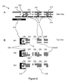
- Figures 1A and 1B illustrate first and second top views, respectively, of a droplet actuator 100 in use during a first and second phase, respectively, of a droplet splitting operation.
- Droplet actuator 100 makes use of an arrangement that is not suitably arranged for efficiently splitting a droplet using the specific technique shown without loss of magnetically responsive beads.
- Droplet actuator 100 includes a first substrate 110 and a second substrate (not shown) arranged with a gap therebetween, which serves as a fluid path.
- First substrate 110 includes a set of droplet operation electrodes 112 configured for conducting droplet operations on slug-shaped droplet 114, which is suspended in a filler fluid and includes magnetically responsive beads 116.
- a magnet 118 may be arranged in sufficient proximity to droplet operation electrodes 112 to permit some degree of immobilization of the magnetically responsive beads 116.
- Figures 1A and 1B show a splitting operation that is taking place in the presence of a magnetic field produced within droplet actuator 100 by magnet 118.
- the placement of magnet 118 is not suitable for localizing substantially all of magnetically responsive beads 116 in a centralized location (e.g., away from the edges of the droplet) within the portion of droplet 114 that is selected to retain the beads after the splitting operation. Consequently, a certain quantity of magnetically responsive beads 116 bridge splitting zone 120 during the droplet splitting operation, as shown in Figure 1A , and a loss of beads results, as shown in Figure 1B.
- Figure 1B shows a first droplet 122 that contains a certain quantity of the original quantity of magnetically responsive beads 116 and a second droplet 124 that contains a certain remaining quantity of the original quantity of magnetically responsive beads 116.
- the end result of the illustrated splitting operation is a loss of magnetically responsive beads 116.
- the inventors have discovered that a contributing factor to the loss of beads is that a full quantity of magnetically responsive beads 116 is not suitably attracted, immobilized, and retained at a centralized location within droplet 114 and/or at a sufficient distance from splitting zone 120.
- the invention provides improved droplet actuators that have various magnet configurations in which magnets are arranged for efficiently splitting bead-containing droplets and washing magnetically responsive beads are described with reference to Figures 2 , 3 , 4 , 5A, and 5B .
- Figures 2 , 3 , 4 , 5A, and 5B illustrate nonlimiting examples of magnet configurations in combination with a droplet actuator splitting droplets with little or no bead loss, and are, among other things, useful for efficiently washing magnetically responsive beads.
- One or more magnets may be arranged in proximity to a droplet on a droplet actuator such that magnetically responsive beads are suitably attracted and immobilized within the droplet, preferably at a centralized location away from the neck that forms during splitting operations.
- the spitting operation may be performed in a droplet slug which is at a distance from the immobilized beads which is sufficient to reduce or eliminate bead loss.
- one or more magnets may be arranged with respect to the droplet actuator structure above, below, and/or beside, the magnetically-responsive bead-containing droplet and any combinations thereof to achieve this purpose.
- Figures 2A and 2B illustrate side and top views of a droplet actuator 200.
- the magnet is placed at a position which is sufficiently distant from the portion of the droplet which is breaking during the splitting operation, splitting zone 224 (or vice versa, the splitting zone may be said to be placed at sufficient distance from the magnet position), to reduce or eliminate bead loss during a droplet splitting operation.
- the magnet is positioned so that the beads are generally centrally located along a lateral diameter L of the droplet (top view).
- Droplet actuator 200 includes a first substrate 210 and a second substrate 212 separated to provide a gap for conducting droplet operations, though only one substrate is required.
- Droplet actuator 200 may include a magnet 216 that is arranged in sufficient proximity to droplet 218/222 to substantially immobilize magnetically responsive beads 220 during a droplet splitting operation.
- the magnet may be arranged as a component of the droplet actuator and/or in sufficient proximity to the droplet actuator to immobilize the magnetically responsive beads in droplet 218/222 in the gap.
- Droplet 218/222 may be surrounded by a filler fluid (not shown). Droplet 218/222 contains a quantity of magnetically responsive beads 220 immobilized by magnet 216.
- Magnet 216 is positioned relative to one or more droplet operation electrodes 214, in order to localize beads 220 in a region of the portion of the droplet 218/222 that is to form droplet 218 without permitting substantial loss of beads 218 during the droplet splitting operation to droplet 222.
- a splitting operation is achieved without substantial loss of magnetic beads 220 by: as shown in 201, providing a droplet actuator 200 with electrodes activated (ON) to form combined droplet 218/222 and magnet 216 is arranged in a position which causes substantially all of magnetically responsive beads 220 to be attracted to magnet 216 in a zone of droplet 218/222 that prevents substantial loss of magnetically responsive beads 220 to droplet 222.
- Magnet 216 may be arranged so that magnetically responsive beads 220 attracted thereto are localized at a generally centralized location along lateral diameter L within combined droplet 218/222 and away from the droplet split zone 224.
- an intermediate electrode is deactivated (OFF) to cause splitting at split zone 224.
- Substantially all magnetically responsive beads 220 are retained in droplet 218, and droplet 222 is formed and is substantially free of magnetically responsive beads 220, as shown in 203.
- a process for washing magnetically responsive beads 220 may, in one embodiment, involve the repetition of droplet merging (with a wash droplet), bead immobilization, splitting, and bead resuspension operations until acceptable levels of washing are achieved.
- Figure 3 illustrates a side view of a droplet actuator 300.
- Droplet actuator 300 is generally configured as described in Figure 2 , except that it includes two magnets, magnet 310a and 310b, arranged below and above droplet 218.
- the magnets may be integral with droplet actuator 300 and/or arranged in close proximity to the outer side of first substrate 210 and second substrate 212.
- the magnets 310a and 310b may be arranged such that opposite poles are facing one another. In one example, the north or positive pole of magnet 310a is facing the south or negative pole of magnet 310b, as shown in Figure 3 .
- Magnets 310a and 310b may be separate magnets or, alternatively, magnets 310a and 310b may be opposite poles of a single U-shaped, C-shaped, or horseshoe-shaped permanent magnet or electromagnet.
- the arrangement of magnets 310a and 310b may cause magnetically responsive beads 220 to be immobilized and retained in a column-shaped cluster.
- the magnets are preferably arranged to localize beads within droplet 218 in a position which is away from splitting zone 224 in the portion of the combined droplet (not shown) in which the beads are to be retained. Further, the magnets are preferably aligned to centrally localize the beads along lateral diameter L within the combined droplet (not shown).
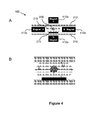
- Figures 4A and 4B illustrate side views of a droplet actuator 400.
- Droplet actuator 400 is generally configured like droplet actuator 200 described in Figure 2 , except that it includes four magnets arranged at positions surrounding the droplet.
- the arrangement illustrates the embodiment in which multiple magnet pairs with positive/negative poles facing each other are arranged to generally centrally locate beads 220 in the combined droplet prior to splitting.
- the beads are generally centrally located along a vertical dimension V and a lateral dimension L.
- droplet actuator 400 includes four magnets, such as a magnet 410a, 410b, 410c, and 410d.
- Magnets 410a and 410b may be arranged in close proximity to the droplet, equally spaced on either side of the droplet, with opposite poles facing each other.
- the north pole of magnet 410a may face the south pole of magnet 410b.
- Magnets 410c and 410d may be arranged in close proximity to the droplet, equally spaced on either side of the droplet, with opposite poles facing each other.
- the north pole of magnet 410d may face the south pole of magnet 410c.
- Magnet pair 410a/410b may generally be aligned at right angles around the droplet relative to magnet pair 410c/410d.
- magnet pair 410a/410b has a vertical orientation around the droplet
- magnet pair 410c/410d has a horizontal orientation around the droplet. Any orientation around the droplet achieving the generally central localization of beads along lateral dimension L and vertical dimension V will suffice to achieve the desired central immobilization.
- Magnets 410a and 410b may be arranged in close proximity to the outer side of first substrate 210 and second substrate 212, respectively, such that the magnetic field of magnets 410a and 410b may pass through the gap between first substrate 210 and second substrate 212 of droplet actuator 400. Magnets 410a and 410b are arranged such that opposite poles are facing one another. In one example, the north pole of magnet 410a is facing the south pole of magnet 410b, as shown in Figure 4 .
- magnets 410c and 410d are arranged in close proximity to a first side and a second side, respectively, of droplet actuator 400, such that the magnetic field of magnets 410c and 410d may pass through the gap of droplet actuator 400 and perpendicular to the magnetic field of magnets 410a and 410b.
- Magnets 410c and 410d are arranged such that opposite poles are facing one another. In one example, the north pole of magnet 410d is facing the south pole of magnet 410c, as shown in Figure 4 .
- Magnets 410a and 410b may be separate magnets or, alternatively, magnets 410a and 410b may be opposite poles of a single U-shaped, C-shaped, or horseshoe-shaped permanent magnet or electromagnet.
- magnets 410c and 410d may be separate magnets or, alternatively, magnets 410c and 410d may be opposite poles of a single U-shaped, C-shaped, or horseshoe-shaped permanent magnet or electromagnet.
- the magnetically responsive beads 220 are magnetically immobilized and retained in a cluster that is centralized within the combined droplet and retained in droplet 218 following the splitting operation.
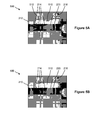
- Figures 5A and 5B illustrate a first and second top view, respectively, of a droplet actuator 500 during a first and second phase, respectively, of a droplet splitting operation.
- Droplet actuator 500 may alternatively be configured like any of the example droplet actuators 200, 300, and 400.
- Droplet actuator 500 of Figures 5A and 5B makes use of magnet forces that are suitably arranged for use in a splitting operation designed to result in substantially complete retention of beads in a single droplet, such as a process for washing magnetically responsive beads.
- Figures 5A and 5B show a splitting operation that is taking place at a sufficient distance from localized beads 220 to permit a splitting operation that results in substantially complete retention of magnetically responsive beads in droplet 218 and a droplet that is substantially free of magnetically responsive beads.
- the position of magnet face 510 is suitably arranged to magnetically immobilize substantially all of magnetically responsive beads 220 at a centralized location within the droplet and at a distance from the splitting zone that is sufficient to achieve the desired retention of magnetically responsive beads 220 in droplet 218.
- substantially no quantity of magnetically responsive beads 220 bridges a splitting zone 512 during the droplet splitting operation, as shown in Figure 5A , and substantially no loss of beads occurs.
- Figure 5B shows droplet 218 that contains substantially all magnetically responsive beads 220.
- the end result of a splitting operation that takes place substantially outside of the magnet forces is that there is substantially no loss of magnetically responsive beads 220 because substantially all of magnetically responsive beads 220 are suitably attracted, immobilized, and retained at a centralized location within the fluid.
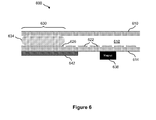
- Figure 6 illustrates a side view of a droplet actuator 600 that includes a magnetic shield for reducing the crossover of magnetic fields.
- Droplet actuator 600 includes a top plate 610 and a bottom plate 614 that are arranged having a gap 618 therebetween.
- An arrangement of electrodes 622 e.g., electrowetting electrodes, may be associated with bottom plate 614 for performing droplet operations and an electrode, such as reservoir electrode 626 that is associated with a fluid reservoir 630 that contains a quantity of fluid 634.
- One or more droplets may be dispensed from the quantity of fluid 634 of reservoir 630 for manipulation along electrodes 622.
- fluid 634 and any droplets dispensed therefrom may optionally contain beads (not shown), which may, in some cases, be magnetically responsive.
- Droplet actuator 600 further includes a magnet 638 that is arranged in proximity to the one or more electrodes 622.
- Magnet 638 may be arranged in sufficient proximity to electrodes 622 in order to permit immobilization of magnetically responsive beads (not shown), e.g., in a droplet positioned on an electrode.
- the purpose of magnet 638 is to magnetically immobilize and retain magnetically responsive beads during a droplet splitting operation, e.g., a splitting operation that may be performed in a process for washing magnetically responsive beads.
- droplet actuator 600 includes a magnetic shield 642 that is arranged in sufficient proximity to fluid reservoir 630 to shield the contents thereof from nearby magnetic fields, such as the magnetic field of magnet 638.
- Magnetic shield 642 may, for example, be formed of Mu-metal that has sufficiently high magnetic permeability and that is suitable to reduce, preferably substantially eliminate, unwanted magnetic fields from the magnet within fluid reservoir 630.
- magnetic shield 642 may be formed of Mu-metal that is supplied by McMaster-Carr (Elmhurst, IL).
- Other examples of magnetic shield 642 materials include Permalloy, iron, steel and nickel.
- Droplet actuator 600 is not limited to one magnetic shield and one magnet only, any number of magnetic shields and magnets may be installed therein. Therefore, by use of one or more magnetic shields, the exposure of magnetic beads (not shown) within droplets to magnetic fields may be limited to desired regions only of droplet actuator 600. Magnetic shields may be included on any surface of the droplet actuator and in any arrangement which facilitates suitable shielding.
- a droplet actuator may be employed to perform multiple assays in parallel and, consequently, there may be a need for generally simultaneous washing of the various magnetic beads that may be manipulated within multiple lanes of electrodes.
- a wash operation or assay that is performed at a certain location using an associated magnet may be affected by the magnetic field of a distant magnet (i.e., crossover of magnetic fields).
- crossover of magnetic fields between any two magnets may be reduced, preferably substantially eliminated, via the strategic placement of one or more magnetic shields, such as magnetic shield 642, within the droplet actuator.
- Figure 7 illustrates a top view of a droplet actuator 700 that includes a magnet whose poles are oppositely arranged for reducing the crossover of magnetic fields.
- Droplet actuator 700 includes an arrangement of electrodes 710, e.g., electrowetting electrodes, for performing droplet operations on one or more droplets (not shown). Additionally, a magnet 714 is arranged in close proximity to a first lane of electrodes 710, a magnet 718 is arranged in close proximity to a second lane of electrodes 710, a magnet 722 is arranged in close proximity to a third lane of electrodes 710, and a magnet 726 is arranged in close proximity to a fourth lane of electrodes 710. Magnets 714, 718, 722, and 726 may be arranged in sufficient proximity to electrodes 710 in order to permit immobilization of magnetically responsive beads (not shown) within one or more droplets (not shown) located on one or more of the electrodes.
- electrodes 710 e.g., electrowetting electrodes
- the poles of adjacent magnets are oppositely arranged, which causes the adjacent magnetic fields to cancel.
- the north pole of magnet 722 is oriented upward
- the south pole of magnet 726 is oriented upward. In this way, the magnetic fields are cancelled and the crossover of magnetic fields between magnets 714, 718, 722, and 726 may be reduced, preferably substantially eliminated.
- Figure 8 illustrates a map 800 of magnetic fields arranged in a relationship such as the one shown in Figure 7 .
- the invention also provides techniques for reducing carryover in a droplet actuator, as well as techniques for improving detection operations.
- Figure 9 illustrates a top view of a droplet actuator 900 by which an operation to reduce carryover at a droplet detection region may be performed.
- Droplet actuator 900 includes an arrangement of electrodes 910, e.g., electrowetting electrodes, for subjecting droplets to droplet operations. Additionally, droplet actuator 900 includes a designated detection region 914 at, for example, a certain electrode 910. Detection region 914 is used to detect droplets positioned thereon or passing therethrough during droplet operations. In one example, droplet detection is performed using a photomultiplier tube (PMT) or photon-counting PMT that is associated with detection region 914.
- PMT photomultiplier tube
- a PMT (not shown) is used to measure light (i.e., detect photons) emitted from a droplet (e.g., due to fluorescence and/or chemiluminescence) when at the electrode that is associated with detection region 914.
- a build up of substances at a detection region may occur due to carryover, which involves beads or other substances being left behind on surfaces and/or in filler fluid during droplet operations. Carryover may interfere with accurate detection of signals from subsequent droplets and/or interfere with droplet operations by affected electrodes.
- a droplet sequencing operation of the invention reduces, preferably substantially eliminates, carryover at detection region 914 by providing a series of alternating assay droplets 918 and wash droplets 922.
- an assay droplet 918a passes through detection region 914, followed by a wash droplet 922a, followed by an assay droplet 918b, followed by a wash droplet 922b, followed by an assay droplet 918c, followed by a wash droplet 922c, followed by an assay droplet 918d, which is followed by a wash droplet 922d.
- wash droplets 922a, 922b, 922c, and 922d perform a cleaning operation of the surfaces that are associated with detection region 914.
- the cleaning process of the invention is not limited to the sequence that is shown in Figure 9 . Any sequence is possible as long as the sequence includes a suitable number of wash droplets in order to suitably clean the detection region.
- the larger droplet may be subjected to droplet operations as a slug (e.g., a slug occupying 4 electrodes) or as a single large droplet (e.g., a 4X droplet occupying as many electrodes as it naturally covers without being formed into a slug).
- a slug e.g., a slug occupying 4 electrodes
- a single large droplet e.g., a 4X droplet occupying as many electrodes as it naturally covers without being formed into a slug.
- Each arrangement may result in a different cleaning result. It is also not necessary for the assay droplets and wash droplets to follow the same path. For example, their paths may intersect at the location needing to be cleaned.
- FIGs 10A and 10B illustrate a top view of a droplet actuator 1000 by which another operation for reducing carryover may be performed.
- Droplet actuator 1000 includes an arrangement of electrodes 1010, e.g., electrowetting electrodes, for performing droplet operations on one or more droplets, such as assay droplets 1014 and 1018 ( Figure 10A ) and wash droplet 1022 ( Figure 10B ).
- electrodes 1010 e.g., electrowetting electrodes
- a magnet 1026 is arranged in close proximity to a certain electrode 1010.
- Magnet 1026 may be arranged in sufficient proximity to the certain electrode 1010 in order to permit immobilization of magnetically responsive beads within one or more droplets, such as magnetic beads 1030 within assay droplet 1014.
- a quantity of "satellite" droplets may be left behind at the point at which the split occurs.
- a droplet split operation by which assay droplet 1014 is formed by splitting from assay droplet 1018 may result in a certain quantity of satellite droplets 1034 being left behind upon a certain electrode 1010.
- Satellite droplets, such as satellite droplets 1034 may be the source of carryover (cross contamination) from one droplet to another, which is not desired.
- Figure 10B illustrates that a wash droplet, such as wash droplet 1022, may be transported along electrodes 1010 subsequent to the assay operations of, for example, assay droplets 1018 and 1014 in order to capture satellite droplets 1034 and transport them away prior the next assay operation occurs.
- electrodes 1010 are cleaned between assay operations.
- the cleaning process of the invention is not limited to the sequence that is shown in Figures 10A and 10B . Any sequence is possible as long the sequence includes a suitable number of wash droplets in order to suitably clean the electrodes.
- FIGS 11A, 11B, and 11C illustrate side views of droplet actuator 1100 by which respective operations for improving the sensitivity of droplet detection may be performed.
- Droplet actuator 1100 includes a top plate 1110 and a bottom plate 1114 that are arranged having a gap 1118 therebetween.
- An arrangement of electrodes 1122 e.g., electrowetting electrodes, may be associated with bottom plate 1114 for performing droplet operations on a droplet 1126.
- a PMT window 1130 may be associated with top plate 1110, by which a PMT (not shown) is used to measure light (i.e., detect photons 1134) emitted from droplet 1126.
- Figure 11A shows a method of improving the sensitivity of droplet detection by spreading out a droplet, such as droplet 1126, in order to increase the surface area that is exposed to PMT window 1130 and, thus, increase the number of photons 1134 that may be detected.
- a droplet may be spread linearly across one or more electrodes 1122 depending on the volume of the droplet.
- a buffer droplet may be added to make the droplet larger, as long as losses due to dilution by the buffer droplet are offset by the increased droplet area exposed to the PMT.
- Figure 11B shows droplet 1126 that is spread continuously across multiple electrodes 1122, which increases the number of photons 1134 that may reach PMT window 1130 and may be detected by the PMT.
- Figure 11C shows a scenario wherein droplet 1126 is split up into multiple droplets 1126, such as droplets 1126a, 1126b, 1126c, and 1126d that are on multiple electrodes 1122.
- the surface area that is exposed to PMT window 1130 is increased, which increases the number of photons 1134 that may reach PMT window 1130 and may be detected by the PMT.
- the spreading of a droplet, such as droplet 1126 is not limited to linear spreading only.
- the droplet may be spread two dimensions, such as across a grid or array or electrodes 1122, in order to increase the surface area that is exposed to PMT window 1130.
- one or more large-area electrodes may be provided, across which one or more droplets may be spread.
- Figure 12 illustrates a top view of a droplet actuator 1200 for improving the sensitivity of droplet detection.
- Droplet actuator 1200 includes an arrangement of electrodes 1210, e.g., electrowetting electrodes, for performing droplet operations on multiple droplets 1214. Additionally, droplet actuator 1200 may include a droplet detection region 1218 that has an associated PMT (not shown) for measuring light that is emitted from a certain droplet 1214 when present. In order to reduce, preferably substantially eliminate, the carryover of light from a distant droplet 1214 to droplet detection region 1218, a minimum distance d is maintained in all directions between the outer perimeter of droplet detection region 1218 and any distant droplets 1214 within droplet actuator 1200, as shown in Figure 12 .
- the minimum distance d is sufficiently large to reduce, preferably substantially eliminate, the carryover of light from a distant droplet 1214 to droplet detection region 1218.
- a spacing is maintained during detection between the target droplet 1214 that is being measured and a distant droplet 1214, such that the carryover of light from the distant droplet 1214 to droplet detection region 1218 is reduced, preferably substantially eliminated.
- the distance d is an integer multiple m of a unit electrode size, and the droplet detection may be conducted on a set of electrodes which are electrically connected as an m phased bus.
- Figure 13 (described below) describes a scenario wherein the real-estate with a droplet actuator is limited and, therefore, sufficient spacing between droplets, as described in Figure 12 , may not be achieved.
- cross-over from nearby droplets is eliminated by using optical elements, such as one or more lenses, which focus only light from the droplet being interrogated onto the sensor and eliminates signal from other droplets.
- optical elements such as one or more lenses
- Figure 13 illustrates a side view of a droplet actuator 1300 for improving the sensitivity of droplet detection.
- Droplet actuator 1300 includes a top plate 1310 and a bottom plate 1314 that are arranged having a gap 1318 therebetween.
- An arrangement of electrodes 1322 e.g., electrowetting electrodes, may be associated with bottom plate 1314 for performing droplet operations on droplets, such as a droplet 1326 and a droplet 1330.
- a PMT window 1334 may be associated with top plate 1310, by which a PMT (not shown) is used to measure light (i.e., detect photons 1338) that is emitted from, for example, droplet 1326.
- a mask 1342 is provided upon top plate 1310. The purpose of mask 1342 is to block light from a distant droplet from carrying over to PMT window 1334, which is the detection region of a target droplet.
- Mask 1342 may be formed upon top plate 1310 via a layer of any light-absorbing material, as long as the material that is used is compatible with the electrowetting process and does not unduly interfere with the droplet actuator operations.
- mask 1342 may be formed by applying a layer of black paint to top plate 1310, such that one or more windows, such as PMT window 1334, are provided in selected detection regions of droplet actuator 1300.
- mask 1342 reduces, preferably substantially eliminates, the carry over of light from distant droplet 1330 to the target droplet 1326 at PMT window 1334.
- the mask 1342 is formed by an opaque conductor on the side of the top plate 1310 facing the droplet.
- the conductor may, for example, be aluminum, chromium, copper, or platinum.
- the conductor may additionally serve as an electrical reference electrode.
- Figures 14A and 14B illustrate top views of a modular droplet actuator assembly 1400, which is a nonlimiting example of a universal assembly for orienting a magnet assembly to a droplet actuator.
- Modular droplet actuator assembly 1400 may include, for example, a mount 1410, a magnet assembly 1420, and a droplet actuator 1430.
- Figure 14A shows modular droplet actuator assembly 1400 when disassembled.
- Figure 14B shows modular droplet actuator assembly 1400 when assembled.
- Magnet assembly 1420 may include a substrate 1424 upon which is mounted one or more magnets 1428, as shown in Figure 14A .
- the magnets 1428 may be permanently affixed to substrate 1424 or may be removable.
- Removable magnets 1428 facilitate selection by a user of magnets having desired properties, such as desired magnet strength.
- a droplet actuator instrument is provided with a droplet actuator assembly 1400 including a mount 1410 and a magnet assembly 1420 without magnets.
- the user is also provided with magnets having specified properties which may be affixed by the user to the magnet assembly 1420.
- the user is also provided with sets of magnets having various specified characteristics such that the user may select a set of one or more magnets having desired properties and affix the selected set to the magnet assembly 1420.
- Magnets may be marked or coded (e.g., color coded) to facilitate selection of magnets having appropriate properties, as well as marked to show the orientation of the magnet's magnetic field (e.g., by color coding or otherwise marking the North and South faces of the magnets).
- the magnet assembly 1420 may be marked to show the desired orientation of magnets inserted therein, and in some embodiments, magnets may be shaped to permit them to be affixed to the magnet assembly 1420 only in an appropriate orientation.
- the user may be provided with magnet assemblies 1420 having magnets already affixed thereto, wherein the magnet assemblies 1420 each have different magnet configurations, e.g., sets of magnets having different properties.
- the user may select the magnet configuration having magnets having properties appropriate to the user's desired use for the instrument.
- Magnet assembly 1420 may be marked or otherwise color coded to facilitate selection by the user. Magnet properties may, for example, be selected based on the properties of beads selected by the user.
- Droplet actuator 1430 may include a substrate 1434 upon which is an arrangement of electrodes 1438, e.g., electrowetting electrodes, as shown in Figure 14A .
- a second (top) substrate may also be included (not shown).
- Magnet assembly 1420 is designed such that magnets 1428 substantially align with certain electrodes 1438 of interest on droplet actuator 1430.
- parallel configurations of magnets may be present for conducting parallel assay steps on droplet actuator 1430.
- Magnets may be configured and oriented, for example, according to the various configurations and orientations described herein.
- Mount 1410 may serve as a universal platform for mounting a magnet assembly, such as magnet assembly 1420, and a droplet actuator, such as droplet actuator 1430.
- mount 1410 is configured to accept a wide variety of magnet assemblies 1420 and a wide variety of droplet actuators 1430.
- Magnet assembly 1420 may include one or more magnets arranged in any of a variety of patterns and employing any of a variety of magnet properties.
- Figure 14 illustrates a row of magnets, but magnets may also be provided in a grid or any arrangement that places the magnets in their proper position in relation to the droplet actuator 1430 in order to facilitate desired operations on the droplet actuator.
- magnet assembly 1420 and droplet actuator 1430 may be installed into mount 1410 via respective fittings 1418 and 1414.
- Fittings may, for example, involve slots into which the mount 1410 may be fitted, openings on the mount 1410 for accepting posts on the magnet assemblies 1420 or vice versa, openings on the mount 1410 for accepting screws on the magnet assemblies 1420, threaded posts for accepting bolts, various spring loaded mechanisms, recessed trays, complimentary fittings, and the like. Any mechanism which facilitates sufficiently secure attachment to permit the device to function for its intended purpose will suffice.
- mount 1410 may include multiple fittings for multiple possible positions of magnet assembly 1420 and/or droplet actuator 1430, and/or mounting of multiple magnet assemblies 1420 and/or multiple droplet actuators 1430 in a single mount 1410. Further, mount 1410 may be configured to permit magnet assemblies 1420 to be mounted above, below and/or beside the droplet actuator 1430, i.e., in any relationship with the droplet actuator. With droplet actuator 1430 installed in modular mount 1410, any magnet assembly of interest, such as magnet assembly 1420, may be inserted into modular droplet actuator assembly 1400 via, for example, the slot.
- Figure 15 illustrates a side view of a modular droplet actuator assembly 1500, which is another nonlimiting example of a universal assembly for orienting a magnet assembly to a droplet actuator, similar to the assembly 1400 shown in Figure 14 , except that mount 1410 is replaced with a mount 1510.
- Mount 1510 includes recessed trays into which magnet assembly 1420 and droplet actuator 1430 may be fitted in order to provide a "drop in" method of loading.
- an aspect of the invention is that the slots or other attachment means serve to orient the magnet substrate and the droplet actuator so as to align the magnets on the magnet assembly with the appropriate electrodes or electrode paths on the droplet actuator. In this manner, the magnets may be removed when not needed for an assay. Additionally, different magnet mounts with different distributions of magnets may be provided for different types of assays or different droplet actuator layouts.
- magnets selected for use with the invention may be permanent or electromagnets. There may be a relationship between the magnetically responsive content of the beads in the droplet and the magnetic strength/pull force. Therefore, the magnetic strength/pull force of the magnet may be selected relative to the responsiveness of the magnetic beads such that it is:
- the magnet may have high magnetic strength (in Tesla) with lesser pull force (in pounds).
- magnet is a neodymium permanent magnet that has a surface field strength of about 1 Tesla (T).
- the magnet is an electromagnet that has a surface field strength of about 1 T, which may be turned on and off electronically. Where a permanent magnet is used, the magnet may be moved away from the magnetically responsive bead-containing droplet for uses in which it is desirable to remove the influence of the magnetic field.
- ranges of magnetic strength that generally encompasses the useful strength of the present invention can include: a broad range of 0.01 T to 100 T (pulsed) or 45 T (continuous); an intermediate range of 0.01 T to 10 T; and a narrow range of 0.1 T to 1 T (preferably 0.5 T).
- Droplets including magnetic beads and subjected to droplet splitting operations may include any of a wide variety of samples, reagents, and buffers useful for conducting assays using the beads.
- the droplet may include a buffer, such as a phosphate-buffered saline (PBS) buffer with a surfactant that is suitable for use in magnetic based immunoassays.
- PBS phosphate-buffered saline
- PBS phosphate-buffered saline
- surfactants are those which facilitate immobilization and/or resuspension of beads following immobilization by magnetic forces.
- the surfactant and amount of surfactant may be adjusted to provide a substantial improvement in resuspension as compared to a control solution lacking the surfactant.
- the droplet includes PBS buffer with about 0.01% Tween ® 20.
- a hydrophilic polymer and/or surfactant may be included in the droplet to facilitate retention and resuspension of magnetically responsive beads during splitting operation.
- the droplet may include a wide variety of liquids immiscible with the filler fluid.
- buffers include, but are not limited to, phosphate-buffered saline (PBS) buffer and Tris buffer saline.
- the droplet fluid includes a buffer, such as the PBS buffer, and any surfactant that is suitable for use in magnetic based immunoassays.
- Preferred hydrophilic polymers and surfactants are those which facilitate resuspension of beads following immobilization by magnetic forces.
- the surfactant and amount of surfactant may be adjusted to provide a substantial improvement in resuspension as compared to a control solution lacking the surfactant.
- Examples of surfactants that are suitable for use in magnetic based immunoassays include, but are not limited to, polysorbate 20, which is commercially known as Twee ® 20, and Triton X-100.
- Tween ® 20 may be supplied by, for example, Pierce Biotechnology, Inc. (Woburn, MA).
- Triton ® X-100 may be supplied by, for example, Rohm & Haas Co (Philadelphia, PA).
- the droplet fluid within the droplet actuator is a mix of PBS with Tween ® 20 in the range of from about 0.001% to about 0.1%. In another example, the droplet fluid within the droplet actuator is a mix of PBS with about 0.01 % Tween ® 20.
- pluronic surfactants polyethylene glycol (PEG), methoxypolyethylene glycol (MPEG), poly-sorbate (polyoxyethylene sorbitan monooleates or Tween®), polyoxyethylene octyl phenyl ether (Triton X-100®), polyvinyl pyrollidone, polyacrylic acid (and crosslinked polyacrylic acid such as carbomer), polyglycosides (nonionic glycosidic surfactants such as octyl glucopyranoside) and soluble polysaccharides (and derivatives thereof) such as heparin, dextrans, methyl cellulose, propyl methyl cellulose (and other cellulose esters and ethers), dextrins, maltodextrins, galactomannans, arabinogalactans, beta glucans, alginates, agar, carrageenan, and plant gums such as xanthan gum, psyllium, guar gum
- Patents 6,773,566 entitled, “Electrostatic Actuators for Microfluidics and Methods for Using Same,” issued on August 10, 2004 and 6,565,727 , entitled, “Actuators for Microfluidics Without Moving Parts,” issued on January 24, 2000, both to Shenderov et al.; and International Patent Application No. PCT/US 06/47486 to Pollack et al. , entitled, “Droplet-Based Biochemistry,” filed on December 11, 2006, the disclosures of which are incorporated herein by reference. Droplet actuator techniques for immobilizing magnetic beads and/or non-magnetic beads are described in the foregoing international patent applications and in Sista, et al., U.S. Patent Application Nos.
- the droplet is a sample fluid, such as a biological sample, such as whole blood, lymphatic fluid, serum, plasma, sweat, tear, saliva, sputum, cerebrospinal fluid, amniotic fluid, seminal fluid, vaginal excretion, serous fluid, synovial fluid, pericardial fluid, peritoneal fluid, pleural fluid, transudates, exudates, cystic fluid, bile, urine, gastric fluid, intestinal fluid, fecal samples, fluidized tissues, fluidized organisms, biological swabs and biological washes.
- a biological sample such as whole blood, lymphatic fluid, serum, plasma, sweat, tear, saliva, sputum, cerebrospinal fluid, amniotic fluid, seminal fluid, vaginal excretion, serous fluid, synovial fluid, pericardial fluid, peritoneal fluid, pleural fluid, transudates, exudates, cystic fluid, bile, urine, gastric fluid, intestinal fluid, f
- the fluid that is loaded includes a reagent, such as water, deionized water, saline solutions, acidic solutions, basic solutions, detergent solutions and/or buffers.
- a reagent such as water, deionized water, saline solutions, acidic solutions, basic solutions, detergent solutions and/or buffers.
- the fluid that is loaded includes a reagent, such as a reagent for a biochemical protocol, such as a nucleic acid amplification protocol, an affinity-based assay protocol, a sequencing protocol, and/or a protocol for analyses of biological fluids.
- the gap is typically filled with a filler fluid.
- the filler fluid may, for example, be a low-viscosity oil, such as silicone oil.
- Other examples of filler fluids are provided in International Patent Application No. PCT/US 06/47486 , entitled, "Droplet-Based Biochemistry,” filed on December 11, 2006.
- droplets with beads can be combined using droplet operations with one or more wash droplets. Then, while retaining the beads (e.g., physically or magnetically) using magnet configurations of the invention, the merged droplet may be divided using droplet operations into two or more droplets: one or more droplets with beads and one or more droplets without a substantial amount of beads. In one embodiment, the merged droplet is divided using droplet operations into one droplet with beads and one droplet without a substantial amount of beads.
- each execution of a washing protocol results in retention of sufficient beads for conducting the intended assay without unduly detrimental effects on the results of the assay.
- each division of the merged droplet results in retention of more than 90, 95, 97, 98, 99, 99.1, 99.2, 99.3, 99.4, 99.5, 99.6, 99.7, 99.8, 99, 99.9. 99.99, 99.999, 99.9999, 99.99999, or 99.999999 percent of beads.
- each execution of a washing protocol to achieve a predetermined reduction in the concentration and/or amount of removed substance results in retention of more than 99, 99.1, 99.2, 99.3, 99.4, 99.5, 99.6, 99.7, 99.8, 99, 99.9. 99.99, 99.999, 99.9999, 99.99999, or 99.999999 percent of beads.
- the amount of retained beads is calculated and the results are adjusted accordingly.
- beads can be washed in reservoirs in which the bead-containing droplet and wash droplets are combined, beads are retained (for example by a magnet, by physical structures, electrostatic forces), and droplets lacking beads are dispensed from the reservoir using droplet operations.
- beads can be washed by dilute-and-dispense strategy whereby a wash buffer is added to the reservoir to dilute the contents, magnetically responsive beads are localized within the reservoir with a magnet and most of the solution is dispensed from the reservoir, and this cycle is repeated till acceptable levels of washing are achieved.
- washing magnetically responsive beads may generally include the following steps:
- Step (5) is not required in each washing cycle; however, it may be useful to enhance washing by freeing contaminants which may be trapped in the immobilized beads. Steps may be performed in a different order, e.g., steps (2) and (3) may be reversed. Steps in the washing protocol may be accomplished on a droplet actuator using droplet operations as described herein.
- a hydrophilic polymer and/or surfactant is included to prevent or reduce bead aggregation. Hydrophilic polymers and surfactants should be selected and used in amounts which reduce or eliminate bead aggregation and minimize non-specific adsorption while at the same time not resulting in significant loss of target analytes or reagents from the droplet.
- the hydrophilic polymer and/or surfactant reduces bead clumping in a droplet in a non-gaseous filler fluid and specifically does not serve to reduce molecular adsorption of droplet components to a surface of the droplet actuator.
- the number of magnetically responsive beads can range from 1 to several 100,000's.
- the invention makes use of one to 100 magnetically responsive beads per droplet.
- the invention may make use of 1, 2, 3, 4, 5, 6, 7, 8, 9, 10 ... 100 magnetically responsive beads per droplet.
- the number of magnetically responsive beads is from one to 10. Use of smaller numbers of magnetically responsive beads permits larger beads to be used.
- the invention makes use of one to 100 magnetically responsive beads per droplet, where the beads have an average diameter of about 25 to about 100 microns.
- the invention makes use of one to 10 magnetically responsive beads per droplet, where the beads have an average diameter of about 50 to about 100 microns.
Applications Claiming Priority (5)
| Application Number | Priority Date | Filing Date | Title |
|---|---|---|---|
| US90065307P | 2007-02-09 | 2007-02-09 | |
| US96973607P | 2007-09-04 | 2007-09-04 | |
| US98077207P | 2007-10-17 | 2007-10-17 | |
| US98076207P | 2007-10-17 | 2007-10-17 | |
| EP08729498.9A EP2111554B1 (fr) | 2007-02-09 | 2008-02-11 | Dispositifs actionneurs de gouttelettes et procédés employant des perles magnétiques |
Related Parent Applications (2)
| Application Number | Title | Priority Date | Filing Date |
|---|---|---|---|
| EP08729498.9 Division | 2008-02-11 | ||
| EP08729498.9A Division EP2111554B1 (fr) | 2007-02-09 | 2008-02-11 | Dispositifs actionneurs de gouttelettes et procédés employant des perles magnétiques |
Publications (3)
| Publication Number | Publication Date |
|---|---|
| EP2570811A2 true EP2570811A2 (fr) | 2013-03-20 |
| EP2570811A3 EP2570811A3 (fr) | 2013-12-11 |
| EP2570811B1 EP2570811B1 (fr) | 2014-11-26 |
Family
ID=39495992
Family Applications (4)
| Application Number | Title | Priority Date | Filing Date |
|---|---|---|---|
| EP12191032.7A Active EP2570812B1 (fr) | 2007-02-09 | 2008-02-11 | Procédé d'assemblage d'un dispositif actionneurs de gouttelettes |
| EP12191030.1A Withdrawn EP2573562A3 (fr) | 2007-02-09 | 2008-02-11 | Dispositifs actionneurs de gouttelettes et procédés utilisant des billes magnétiques |
| EP08729498.9A Active EP2111554B1 (fr) | 2007-02-09 | 2008-02-11 | Dispositifs actionneurs de gouttelettes et procédés employant des perles magnétiques |
| EP12191029.3A Active EP2570811B1 (fr) | 2007-02-09 | 2008-02-11 | Dispositifs actionneurs de gouttelettes et procédés employant des perles magnétiques |
Family Applications Before (3)
| Application Number | Title | Priority Date | Filing Date |
|---|---|---|---|
| EP12191032.7A Active EP2570812B1 (fr) | 2007-02-09 | 2008-02-11 | Procédé d'assemblage d'un dispositif actionneurs de gouttelettes |
| EP12191030.1A Withdrawn EP2573562A3 (fr) | 2007-02-09 | 2008-02-11 | Dispositifs actionneurs de gouttelettes et procédés utilisant des billes magnétiques |
| EP08729498.9A Active EP2111554B1 (fr) | 2007-02-09 | 2008-02-11 | Dispositifs actionneurs de gouttelettes et procédés employant des perles magnétiques |
Country Status (11)
| Country | Link |
|---|---|
| US (3) | US9046514B2 (fr) |
| EP (4) | EP2570812B1 (fr) |
| JP (2) | JP5156762B2 (fr) |
| KR (2) | KR101503510B1 (fr) |
| CN (1) | CN101627308B (fr) |
| AU (1) | AU2008212808B2 (fr) |
| BR (1) | BRPI0806831B8 (fr) |
| CA (2) | CA2856143C (fr) |
| DK (1) | DK2111554T3 (fr) |
| ES (1) | ES2423930T3 (fr) |
| WO (1) | WO2008098236A2 (fr) |
Families Citing this family (124)
| Publication number | Priority date | Publication date | Assignee | Title |
|---|---|---|---|---|
| JP5897780B2 (ja) | 2005-01-28 | 2016-03-30 | デューク ユニバーシティ | プリント回路基板上の液滴操作装置及び方法 |
| US8613889B2 (en) | 2006-04-13 | 2013-12-24 | Advanced Liquid Logic, Inc. | Droplet-based washing |
| US20140193807A1 (en) | 2006-04-18 | 2014-07-10 | Advanced Liquid Logic, Inc. | Bead manipulation techniques |
| US8637317B2 (en) | 2006-04-18 | 2014-01-28 | Advanced Liquid Logic, Inc. | Method of washing beads |
| US8470606B2 (en) | 2006-04-18 | 2013-06-25 | Duke University | Manipulation of beads in droplets and methods for splitting droplets |
| WO2009140671A2 (fr) * | 2008-05-16 | 2009-11-19 | Advanced Liquid Logic, Inc. | Dispositifs et procédés actionneurs de gouttelettes pour manipuler des billes |
| US8637324B2 (en) | 2006-04-18 | 2014-01-28 | Advanced Liquid Logic, Inc. | Bead incubation and washing on a droplet actuator |
| US8658111B2 (en) | 2006-04-18 | 2014-02-25 | Advanced Liquid Logic, Inc. | Droplet actuators, modified fluids and methods |
| US8809068B2 (en) | 2006-04-18 | 2014-08-19 | Advanced Liquid Logic, Inc. | Manipulation of beads in droplets and methods for manipulating droplets |
| US10078078B2 (en) | 2006-04-18 | 2018-09-18 | Advanced Liquid Logic, Inc. | Bead incubation and washing on a droplet actuator |
| WO2010042637A2 (fr) * | 2008-10-07 | 2010-04-15 | Advanced Liquid Logic, Inc. | Incubation et lavage de billes sur un actionneur à gouttelettes |
| US7439014B2 (en) * | 2006-04-18 | 2008-10-21 | Advanced Liquid Logic, Inc. | Droplet-based surface modification and washing |
| WO2010027894A2 (fr) * | 2008-08-27 | 2010-03-11 | Advanced Liquid Logic, Inc. | Actionneurs de gouttelettes, fluides modifiés et procédés associés |
| US8716015B2 (en) | 2006-04-18 | 2014-05-06 | Advanced Liquid Logic, Inc. | Manipulation of cells on a droplet actuator |
| WO2009111769A2 (fr) | 2008-03-07 | 2009-09-11 | Advanced Liquid Logic, Inc. | Réactif et préparation et chargement d’un échantillon sur un dispositif fluidique |
| US8685344B2 (en) | 2007-01-22 | 2014-04-01 | Advanced Liquid Logic, Inc. | Surface assisted fluid loading and droplet dispensing |
| US9046514B2 (en) | 2007-02-09 | 2015-06-02 | Advanced Liquid Logic, Inc. | Droplet actuator devices and methods employing magnetic beads |
| EP2109774B1 (fr) | 2007-02-15 | 2018-07-04 | Advanced Liquid Logic, Inc. | Détection de capacité sur un actuateur goutte |
| US8440392B2 (en) | 2007-03-22 | 2013-05-14 | Advanced Liquid Logic Inc. | Method of conducting a droplet based enzymatic assay |
| US8202686B2 (en) | 2007-03-22 | 2012-06-19 | Advanced Liquid Logic, Inc. | Enzyme assays for a droplet actuator |
| KR20100016343A (ko) * | 2007-04-10 | 2010-02-12 | 어드밴스드 리퀴드 로직, 아이엔씨. | 액적 분배 장치 및 그 방법 |
| US8951732B2 (en) | 2007-06-22 | 2015-02-10 | Advanced Liquid Logic, Inc. | Droplet-based nucleic acid amplification in a temperature gradient |
| KR101451955B1 (ko) | 2007-08-24 | 2014-10-21 | 어드밴스드 리퀴드 로직, 아이엔씨. | 액적 작동기 상에서의 비드 조작법 |
| WO2009032863A2 (fr) | 2007-09-04 | 2009-03-12 | Advanced Liquid Logic, Inc. | Actionneur de gouttelette avec substrat supérieur amélioré |
| EP2212683A4 (fr) * | 2007-10-17 | 2011-08-31 | Advanced Liquid Logic Inc | Manipulation de billes dans des gouttelettes |
| US8454905B2 (en) | 2007-10-17 | 2013-06-04 | Advanced Liquid Logic Inc. | Droplet actuator structures |
| US20100236928A1 (en) * | 2007-10-17 | 2010-09-23 | Advanced Liquid Logic, Inc. | Multiplexed Detection Schemes for a Droplet Actuator |
| WO2009052095A1 (fr) | 2007-10-17 | 2009-04-23 | Advanced Liquid Logic, Inc. | Stockage de réactif et reconstitution pour un dispositif de manipulation de gouttelettes |
| WO2009052321A2 (fr) * | 2007-10-18 | 2009-04-23 | Advanced Liquid Logic, Inc. | Actionneurs de gouttelettes, systèmes et procédés |
| WO2009076414A2 (fr) | 2007-12-10 | 2009-06-18 | Advanced Liquid Logic, Inc. | Configurations d'actionneur de gouttelette et procédés |
| KR20100100974A (ko) | 2007-12-23 | 2010-09-15 | 어드밴스드 리퀴드 로직, 아이엔씨. | 액적 작업들을 수행하는 액적 작동기 구성부 및 방법 |
| US8617899B2 (en) * | 2008-02-14 | 2013-12-31 | Palo Alto Research Center Incorporated | Enhanced drop mixing using magnetic actuation |
| US8852952B2 (en) | 2008-05-03 | 2014-10-07 | Advanced Liquid Logic, Inc. | Method of loading a droplet actuator |
| EP2672259A1 (fr) * | 2008-05-13 | 2013-12-11 | Advanced Liquid Logic, Inc. | Procédés, systèmes et dispositifs associés à un positionneur de gouttelettes |
| US20110097763A1 (en) * | 2008-05-13 | 2011-04-28 | Advanced Liquid Logic, Inc. | Thermal Cycling Method |
| US20110311980A1 (en) * | 2008-12-15 | 2011-12-22 | Advanced Liquid Logic, Inc. | Nucleic Acid Amplification and Sequencing on a Droplet Actuator |
| US8877512B2 (en) * | 2009-01-23 | 2014-11-04 | Advanced Liquid Logic, Inc. | Bubble formation techniques using physical or chemical features to retain a gas bubble within a droplet actuator |
| WO2010120080A2 (fr) * | 2009-04-14 | 2010-10-21 | 서울대학교산학협력단 | Structure magnétique à code-couleur |
| EP2599548B1 (fr) * | 2009-05-13 | 2018-07-04 | ibidi GmbH | Support d'échantillon pour le positionnement d'un échantillon organique, biologique et/ou médical |
| US8926065B2 (en) | 2009-08-14 | 2015-01-06 | Advanced Liquid Logic, Inc. | Droplet actuator devices and methods |
| US9091649B2 (en) | 2009-11-06 | 2015-07-28 | Advanced Liquid Logic, Inc. | Integrated droplet actuator for gel; electrophoresis and molecular analysis |
| EP2516669B1 (fr) * | 2009-12-21 | 2016-10-12 | Advanced Liquid Logic, Inc. | Analyses d'enzymes sur un diffuseur à gouttelettes |
| US20130203606A1 (en) * | 2010-02-25 | 2013-08-08 | Advanced Liquid Logic Inc | Method of Preparing a Nucleic Acid Library |
| WO2011126892A2 (fr) | 2010-03-30 | 2011-10-13 | Advanced Liquid Logic, Inc. | Plateforme pour opérations sur des gouttelettes |
| EP2567213B1 (fr) | 2010-05-05 | 2018-01-24 | The Governing Council of the Universtiy of Toronto | Procédé de traitement d'échantillons séchés utilisant un dispositif microfluidique numérique |
| EP2588322B1 (fr) | 2010-06-30 | 2015-06-17 | Advanced Liquid Logic, Inc. | Ensembles actionneurs à gouttelettes et leurs procédés de fabrication |
| WO2012009320A2 (fr) * | 2010-07-15 | 2012-01-19 | Advanced Liquid Logic, Inc. | Système et procédés permettant de favoriser la lyse cellulaire dans des actionneurs à gouttelettes |
| WO2012068055A2 (fr) | 2010-11-17 | 2012-05-24 | Advanced Liquid Logic, Inc. | Détection de capacité dans un organe de commande de gouttelettes |
| WO2012138882A2 (fr) | 2011-04-05 | 2012-10-11 | Purdue Research Foundation | Système micro-fluidique utilisant des micro-ouvertures pour une détection de haut débit de cellules |
| CA2833897C (fr) | 2011-05-09 | 2020-05-19 | Advanced Liquid Logic, Inc. | Retroaction microfluidique utilisant une detection d'impedance |
| EP2707724A4 (fr) | 2011-05-10 | 2015-01-21 | Advanced Liquid Logic Inc | Concentration d'enzymes et dosages |
| BR112014000257A2 (pt) * | 2011-07-06 | 2017-03-01 | Advanced Liquid Logic Inc | armazenamento de reagente em um atuador de gota |
| US8901043B2 (en) | 2011-07-06 | 2014-12-02 | Advanced Liquid Logic, Inc. | Systems for and methods of hybrid pyrosequencing |
| US9513253B2 (en) | 2011-07-11 | 2016-12-06 | Advanced Liquid Logic, Inc. | Droplet actuators and techniques for droplet-based enzymatic assays |
| KR20130009504A (ko) | 2011-07-15 | 2013-01-23 | 삼성전자주식회사 | 개구 조절 방법 및 개구 조절 소자 |
| WO2013016413A2 (fr) * | 2011-07-25 | 2013-01-31 | Advanced Liquid Logic Inc | Dispositif et système d'actionneur à gouttelettes |
| WO2013070627A2 (fr) | 2011-11-07 | 2013-05-16 | Illumina, Inc. | Appareils de séquençage intégré et procédés d'utilisation |
| US9709469B2 (en) * | 2011-11-11 | 2017-07-18 | The Regents Of The University Of California | Valveless microfluidic device |
| WO2013078216A1 (fr) | 2011-11-21 | 2013-05-30 | Advanced Liquid Logic Inc | Dosages de la glucose-6-phosphate déshydrogénase |
| US9068695B2 (en) * | 2012-06-12 | 2015-06-30 | Smrt Delivery Llc | Active guidance of fluid agents using magnetorheological antibubbles |
| US9223317B2 (en) | 2012-06-14 | 2015-12-29 | Advanced Liquid Logic, Inc. | Droplet actuators that include molecular barrier coatings |
| WO2014004577A1 (fr) | 2012-06-25 | 2014-01-03 | The General Hospital Corporation | Tri de particules au moyen de champs magnétiques à gradient élevé |
| IN2015DN00359A (fr) | 2012-06-27 | 2015-06-12 | Advanced Liquid Logic Inc | |
| WO2014035979A1 (fr) * | 2012-08-27 | 2014-03-06 | The Board Of Trustees Of The Leland Stanford Junior University | Matrices bidimensionnelles de pièges magnétiques pour la gestion des gouttelettes |
| JP6410721B2 (ja) * | 2012-10-05 | 2018-10-24 | コーネル ユニヴァーシティー | マクロポーラススカフォールドに埋め込まれたメソポーラス・アセンブリを形成する酵素 |
| WO2014062551A1 (fr) | 2012-10-15 | 2014-04-24 | Advanced Liquid Logic, Inc. | Cartouche microfluidique numérique et système pour la mise en œuvre d'une cuve à circulation |
| US20140322706A1 (en) | 2012-10-24 | 2014-10-30 | Jon Faiz Kayyem | Integrated multipelx target analysis |
| US9957553B2 (en) | 2012-10-24 | 2018-05-01 | Genmark Diagnostics, Inc. | Integrated multiplex target analysis |
| US9366647B2 (en) * | 2013-03-14 | 2016-06-14 | Taiwan Semiconductor Manufacturing Company, Ltd. | Optical detection for bio-entities |
| WO2014100189A1 (fr) * | 2012-12-21 | 2014-06-26 | Luminex Corporation | Actionneur magnétique blindé rotatif |
| US9636689B2 (en) | 2012-12-21 | 2017-05-02 | Luminex Corporation | Rotating magnetic actuator |
| US9492824B2 (en) * | 2013-01-16 | 2016-11-15 | Sharp Kabushiki Kaisha | Efficient dilution method, including washing method for immunoassay |
| CN107015013B (zh) | 2013-01-31 | 2018-12-21 | 卢米耐克斯公司 | 准备测定的系统和方法 |
| CN105228748B (zh) | 2013-03-15 | 2017-10-10 | 金马克诊断股份有限公司 | 用于操纵可变形流体容器的系统、方法和设备 |
| US9341639B2 (en) | 2013-07-26 | 2016-05-17 | Industrial Technology Research Institute | Apparatus for microfluid detection |
| CN111957453B (zh) | 2013-08-13 | 2022-08-19 | 先进流体逻辑公司 | 使用作为流体输入的接通致动器储液器来提高液滴计量的准确度和精度的方法 |
| CA2920390A1 (fr) | 2013-08-30 | 2015-03-05 | Illumina, Inc. | Manipulation de gouttelettes sur des surfaces hydrophiles ou hydrophiles panachees |
| US9498778B2 (en) | 2014-11-11 | 2016-11-22 | Genmark Diagnostics, Inc. | Instrument for processing cartridge for performing assays in a closed sample preparation and reaction system |
| USD881409S1 (en) | 2013-10-24 | 2020-04-14 | Genmark Diagnostics, Inc. | Biochip cartridge |
| CN107267383A (zh) * | 2013-12-18 | 2017-10-20 | 东洋制罐集团控股株式会社 | 培养容器的制造方法和固相化装置 |
| TWI510780B (zh) * | 2014-03-20 | 2015-12-01 | Univ Nat Chiao Tung | 生物檢測設備及生物晶片 |
| WO2015168161A2 (fr) | 2014-04-29 | 2015-11-05 | Illumina, Inc. | Analyse de l'expression de gènes de cellules isolées multiplexées par commutation de matrice et fragmentation et étiquetage (tagmentation) |
| JP2016067277A (ja) * | 2014-09-30 | 2016-05-09 | セイコーエプソン株式会社 | 生体関連物質抽出デバイス及び生体関連物質抽出装置 |
| AU2015330688B2 (en) | 2014-10-09 | 2021-02-11 | Illumina, Inc. | Method and device for separating immiscible liquids to effectively isolate at least one of the liquids |
| US9598722B2 (en) | 2014-11-11 | 2017-03-21 | Genmark Diagnostics, Inc. | Cartridge for performing assays in a closed sample preparation and reaction system |
| WO2016077364A2 (fr) | 2014-11-11 | 2016-05-19 | Genmark Diagnostics, Inc. | Instrument et cartouche pour effectuer des dosages dans un système de réaction et de préparation d'échantillon fermé |
| US10005080B2 (en) | 2014-11-11 | 2018-06-26 | Genmark Diagnostics, Inc. | Instrument and cartridge for performing assays in a closed sample preparation and reaction system employing electrowetting fluid manipulation |
| JP6353155B2 (ja) * | 2014-12-02 | 2018-07-04 | コーニンクレッカ フィリップス エヌ ヴェKoninklijke Philips N.V. | 微小流体工学システムにおける磁性粒子の分散および蓄積 |
| EP3059588B1 (fr) * | 2015-02-18 | 2018-01-10 | Fundacion Tekniker | Procédé et dispositif de détection et de quantification d'analytes |
| EP3061529A1 (fr) * | 2015-02-24 | 2016-08-31 | AdnaGen GmbH | Appareil et procédé pour l'analyse, l'isolement et/ou l'enrichissement de structures cibles dans un échantillon de fluide |
| CN107847930B (zh) | 2015-03-20 | 2020-06-30 | 亿明达股份有限公司 | 在竖直或大致竖直的位置中使用的流体盒 |
| US10464067B2 (en) | 2015-06-05 | 2019-11-05 | Miroculus Inc. | Air-matrix digital microfluidics apparatuses and methods for limiting evaporation and surface fouling |
| CN208562324U (zh) | 2015-06-05 | 2019-03-01 | 米罗库鲁斯公司 | 空气基质数字微流控(dmf)装置 |
| KR20180040669A (ko) | 2015-08-14 | 2018-04-20 | 일루미나, 인코포레이티드 | 유전 특징을 결정하기 위한 자기-반응성 센서를 사용하는 시스템 및 방법 |
| CA3172078A1 (fr) | 2015-08-28 | 2017-03-09 | Illumina, Inc. | Analyse de sequences d'acides nucleiques provenant de cellules isolees |
| CN107921432A (zh) | 2015-09-02 | 2018-04-17 | 伊卢米纳剑桥有限公司 | 改善流控系统中的液滴操作的系统和方法 |
| US10450598B2 (en) | 2015-09-11 | 2019-10-22 | Illumina, Inc. | Systems and methods for obtaining a droplet having a designated concentration of a substance-of-interest |
| RU2719991C2 (ru) | 2015-10-22 | 2020-04-23 | Иллюмина, Инк. | Наполняющая текучая среда для струйных устройств |
| WO2017095845A1 (fr) | 2015-12-01 | 2017-06-08 | Illumina, Inc. | Mécanismes et procédés de stockage et de distribution de liquides |
| DK3384046T3 (da) | 2015-12-01 | 2021-07-12 | Illumina Inc | Digitalt mikrofluidisk system til enkeltcelleisolering og karakterisering af analytter |
| WO2017176896A1 (fr) | 2016-04-07 | 2017-10-12 | Illumina, Inc. | Procédés et systèmes de construction de banques d'acides nucléiques normalisées |
| CN109477873A (zh) * | 2016-07-21 | 2019-03-15 | 西门子医疗保健诊断公司 | 用于ivd自动化系统的磁屏蔽 |
| CA3034064A1 (fr) | 2016-08-22 | 2018-03-01 | Miroculus Inc. | Systeme de retroaction permettant la maitrise des gouttelettes en parallele dans un dispositif microfluidique numerique |
| US11300578B2 (en) | 2016-09-19 | 2022-04-12 | Roche Molecular Systems, Inc. | Instrument for processing cartridge for performing assays in a closed sample preparation and reaction system |
| JP2020515815A (ja) | 2016-12-28 | 2020-05-28 | ミロキュラス インコーポレイテッド | デジタルマイクロ流体デバイスおよび方法 |
| WO2018176161A1 (fr) * | 2017-03-31 | 2018-10-04 | The Governing Council Of The University Of Toronto | Procédés de filtration de suspensions hétérogènes de faible volume dans un dispositif microfluidique numérique |
| WO2018187476A1 (fr) | 2017-04-04 | 2018-10-11 | Miroculus Inc. | Appareils microfluidiques numériques et procédés de manipulation et de traitement de gouttelettes encapsulées |
| WO2019023133A1 (fr) | 2017-07-24 | 2019-01-31 | Miroculus Inc. | Systèmes microfluidiques numériques et procédés à dispositif de collecte de plasma intégré |
| CA3073058A1 (fr) | 2017-09-01 | 2019-03-07 | Miroculus Inc. | Dispositifs microfluidiques numeriques et leurs procedes d'utilisation |
| DE102018125403A1 (de) * | 2017-10-13 | 2019-04-18 | Maxim Integrated Products, Inc. | Analytensensor-package mit abgabechemie und mikrofluidkappe |
| PL3746564T3 (pl) | 2018-01-29 | 2023-05-22 | St. Jude Children's Research Hospital, Inc. | Sposób amplifikacji kwasów nukleinowych |
| US11666914B2 (en) * | 2018-05-09 | 2023-06-06 | Tecan Trading Ag | Cartridge, electrowetting sample processing system and bead manipulation method |
| SG11202102841WA (en) * | 2018-09-28 | 2021-04-29 | Octane Biotech Inc | Magnetic separation |
| CN109603942B (zh) * | 2019-02-15 | 2021-12-24 | 京东方科技集团股份有限公司 | 微流控装置和微流控方法 |
| EP3953041A4 (fr) | 2019-04-08 | 2023-01-25 | Miroculus Inc. | Appareils microfluidiques numériques à cartouches multiples et procédés d'utilisation |
| US11618021B2 (en) * | 2019-06-28 | 2023-04-04 | Wisconsin Alumni Research Foundation | Volume-free reagent addition and exclusion-based sample preparation for streamlined multi-step assays |
| WO2021016614A1 (fr) | 2019-07-25 | 2021-01-28 | Miroculus Inc. | Dispositifs microfluidiques numériques et leurs procédés d'utilisation |
| JP2022547239A (ja) * | 2019-09-10 | 2022-11-10 | ビージーアイ シェンチェン カンパニー リミテッド | 磁性ビーズのマイクロ流体への作用 |
| KR102308065B1 (ko) | 2019-11-08 | 2021-09-30 | 경북대학교 산학협력단 | 입자검출장치 및 이를 이용한 입자검출방법 |
| US20230304066A1 (en) | 2020-09-04 | 2023-09-28 | Baebies, Inc. | Microfluidic based assay for unbound bilirubin |
| CN112934280B (zh) * | 2021-02-01 | 2023-03-10 | 上海中航光电子有限公司 | 一种微流控装置及其检测方法 |
| CN113578406A (zh) * | 2021-09-07 | 2021-11-02 | 北京航空航天大学 | 液滴转移用微柱表面、微柱表面制备方法及液滴转移方法 |
| US11857961B2 (en) | 2022-01-12 | 2024-01-02 | Miroculus Inc. | Sequencing by synthesis using mechanical compression |
| DE102022200663A1 (de) | 2022-01-21 | 2023-07-27 | Robert Bosch Gesellschaft mit beschränkter Haftung | Mikrofluidische Vorrichtung und Verfahren zu ihrem Betrieb |
Citations (6)
| Publication number | Priority date | Publication date | Assignee | Title |
|---|---|---|---|---|
| US647486A (en) | 1899-10-05 | 1900-04-17 | Wellis R Fox | Acetylene-gas generator. |
| EP0872949A2 (fr) | 1997-04-18 | 1998-10-21 | SISME IMMOBILIARE S.p.A. | Moteur synchrone monophasé à aimants permanents |
| US6565727B1 (en) | 1999-01-25 | 2003-05-20 | Nanolytics, Inc. | Actuators for microfluidics without moving parts |
| US6773566B2 (en) | 2000-08-31 | 2004-08-10 | Nanolytics, Inc. | Electrostatic actuators for microfluidics and methods for using same |
| US6911132B2 (en) | 2002-09-24 | 2005-06-28 | Duke University | Apparatus for manipulating droplets by electrowetting-based techniques |
| US20050260686A1 (en) | 1997-11-18 | 2005-11-24 | Bio-Rad Laboratories, Inc. | Multiplex flow assays preferably with magnetic particles as solid phase |
Family Cites Families (210)
| Publication number | Priority date | Publication date | Assignee | Title |
|---|---|---|---|---|
| US4127460A (en) | 1976-10-27 | 1978-11-28 | Desoto, Inc. | Radiation-curing aqueous coatings providing a nonadherent surface |
| US4244693A (en) | 1977-02-28 | 1981-01-13 | The United States Of America As Represented By The United States Department Of Energy | Method and composition for testing for the presence of an alkali metal |
| FR2543320B1 (fr) * | 1983-03-23 | 1986-01-31 | Thomson Csf | Dispositif indicateur a commande electrique de deplacement d'un fluide |
| US5038852A (en) | 1986-02-25 | 1991-08-13 | Cetus Corporation | Apparatus and method for performing automated amplification of nucleic acid sequences and assays using heating and cooling steps |
| KR970007077B1 (ko) * | 1987-03-13 | 1997-05-02 | 코울터 일렉트로닉스 인커퍼레이티드 | 광산란 기술을 이용한 다중-부분식별 분석 방법 |
| US6013531A (en) | 1987-10-26 | 2000-01-11 | Dade International Inc. | Method to use fluorescent magnetic polymer particles as markers in an immunoassay |
| US5225332A (en) | 1988-04-22 | 1993-07-06 | Massachusetts Institute Of Technology | Process for manipulation of non-aqueous surrounded microdroplets |
| GB8917963D0 (en) | 1989-08-05 | 1989-09-20 | Scras | Apparatus for repeated automatic execution of a thermal cycle for treatment of biological samples |
| US5266498A (en) | 1989-10-27 | 1993-11-30 | Abbott Laboratories | Ligand binding assay for an analyte using surface-enhanced scattering (SERS) signal |
| SE467309B (sv) * | 1990-10-22 | 1992-06-29 | Berol Nobel Ab | Hydrofiliserad fast yta, foerfarande foer dess framstaellning samt medel daerfoer |
| US5181016A (en) * | 1991-01-15 | 1993-01-19 | The United States Of America As Represented By The United States Department Of Energy | Micro-valve pump light valve display |
| IL100866A (en) * | 1991-02-06 | 1995-10-31 | Igen Inc | Luminescence test method and device based on magnetic tiny particles, containing many magnets |
| US5370842A (en) | 1991-11-29 | 1994-12-06 | Canon Kabushiki Kaisha | Sample measuring device and sample measuring system |
| US5498392A (en) | 1992-05-01 | 1996-03-12 | Trustees Of The University Of Pennsylvania | Mesoscale polynucleotide amplification device and method |
| WO1994008759A1 (fr) | 1992-10-16 | 1994-04-28 | Thomas Jefferson University | Procede et appareil d'execution robotique de reactions de sequencage de didesoxynucleotides de sanger |
| US5472881A (en) | 1992-11-12 | 1995-12-05 | University Of Utah Research Foundation | Thiol labeling of DNA for attachment to gold surfaces |
| US6152181A (en) | 1992-11-16 | 2000-11-28 | The United States Of America As Represented By The Secretary Of The Air Force | Microdevices based on surface tension and wettability that function as sensors, actuators, and other devices |
| DE69429038T2 (de) | 1993-07-28 | 2002-03-21 | Pe Corp Ny Norwalk | Vorrichtung und Verfahren zur Nukleinsäurevervielfältigung |
| US5486337A (en) * | 1994-02-18 | 1996-01-23 | General Atomics | Device for electrostatic manipulation of droplets |
| US6613560B1 (en) * | 1994-10-19 | 2003-09-02 | Agilent Technologies, Inc. | PCR microreactor for amplifying DNA using microquantities of sample fluid |
| US6673533B1 (en) | 1995-03-10 | 2004-01-06 | Meso Scale Technologies, Llc. | Multi-array multi-specific electrochemiluminescence testing |
| US6319668B1 (en) | 1995-04-25 | 2001-11-20 | Discovery Partners International | Method for tagging and screening molecules |
| US5817526A (en) | 1995-05-09 | 1998-10-06 | Fujirebio Inc. | Method and apparatus for agglutination immunoassay |
| US6130098A (en) | 1995-09-15 | 2000-10-10 | The Regents Of The University Of Michigan | Moving microdroplets |
| US5945281A (en) | 1996-02-02 | 1999-08-31 | Becton, Dickinson And Company | Method and apparatus for determining an analyte from a sample fluid |
| DE19717085C2 (de) | 1997-04-23 | 1999-06-17 | Bruker Daltonik Gmbh | Verfahren und Geräte für extrem schnelle DNA-Vervielfachung durch Polymerase-Kettenreaktionen (PCR) |
| US5998224A (en) | 1997-05-16 | 1999-12-07 | Abbott Laboratories | Magnetically assisted binding assays utilizing a magnetically responsive reagent |
| US20020001544A1 (en) | 1997-08-28 | 2002-01-03 | Robert Hess | System and method for high throughput processing of droplets |
| US7214298B2 (en) * | 1997-09-23 | 2007-05-08 | California Institute Of Technology | Microfabricated cell sorter |
| DE19822123C2 (de) | 1997-11-21 | 2003-02-06 | Meinhard Knoll | Verfahren und Vorrichtung zum Nachweis von Analyten |
| US6063339A (en) | 1998-01-09 | 2000-05-16 | Cartesian Technologies, Inc. | Method and apparatus for high-speed dot array dispensing |
| GB9820755D0 (en) | 1998-09-23 | 1998-11-18 | Xaar Technology Ltd | Drop on demand ink jet printing apparatus |
| US6591852B1 (en) * | 1998-10-13 | 2003-07-15 | Biomicro Systems, Inc. | Fluid circuit components based upon passive fluid dynamics |
| US6294063B1 (en) * | 1999-02-12 | 2001-09-25 | Board Of Regents, The University Of Texas System | Method and apparatus for programmable fluidic processing |
| EP1163052B1 (fr) | 1999-02-23 | 2010-06-02 | Caliper Life Sciences, Inc. | Manipulation de microparticules dans des systemes microfluidiques |
| US6225061B1 (en) * | 1999-03-10 | 2001-05-01 | Sequenom, Inc. | Systems and methods for performing reactions in an unsealed environment |
| EP1041386B1 (fr) | 1999-03-25 | 2007-10-17 | Tosoh Corporation | Analyseur |
| IT1309430B1 (it) | 1999-05-18 | 2002-01-23 | Guerrieri Roberto | Metodo ed apparato per la manipolazione di particelle per mezzo delladielettroforesi |
| US20020051971A1 (en) | 1999-05-21 | 2002-05-02 | John R. Stuelpnagel | Use of microfluidic systems in the detection of target analytes using microsphere arrays |
| FR2794039B1 (fr) * | 1999-05-27 | 2002-05-03 | Osmooze Sa | Dispositif de formation, de deplacement et de diffusion de petites quantites calibrees de liquides |
| US6977145B2 (en) | 1999-07-28 | 2005-12-20 | Serono Genetics Institute S.A. | Method for carrying out a biochemical protocol in continuous flow in a microreactor |
| DE19938002A1 (de) * | 1999-08-11 | 2001-02-15 | Studiengesellschaft Kohle Mbh | Beschichtung mit quervernetzten hydrophilen Polymeren |
| US20030027204A1 (en) | 1999-09-03 | 2003-02-06 | Yokogawa Electric Corporation, A Japan Corporation | Method and apparatus for producing biochips |
| US20040209376A1 (en) | 1999-10-01 | 2004-10-21 | Surromed, Inc. | Assemblies of differentiable segmented particles |
| DE69931787T2 (de) | 1999-11-11 | 2007-05-24 | The Provost, Fellows And Scholars Of The College Of The Holy And Undivided Trinity Of Queen Elizabeth Near Dublin | Vorrichtung und Verfahren zur Verabreichung von Tropfen |
| US6432290B1 (en) * | 1999-11-26 | 2002-08-13 | The Governors Of The University Of Alberta | Apparatus and method for trapping bead based reagents within microfluidic analysis systems |
| JP4240729B2 (ja) * | 2000-02-14 | 2009-03-18 | 日油株式会社 | 臨床検査用微粒子分散剤、検査用試薬、試薬の製造方法、検査方法および用途 |
| US6924792B1 (en) * | 2000-03-10 | 2005-08-02 | Richard V. Jessop | Electrowetting and electrostatic screen display systems, colour displays and transmission means |
| JP3442338B2 (ja) | 2000-03-17 | 2003-09-02 | 株式会社日立製作所 | Dna分析装置、dna塩基配列決定装置、dna塩基配列決定方法、および反応モジュール |
| WO2002007503A1 (fr) | 2000-07-25 | 2002-01-31 | The Regents Of The University Of California | Micropompage par electromouillage |
| CA2314398A1 (fr) | 2000-08-10 | 2002-02-10 | Edward Shipwash | Jeux ordonnes de microechantillons et microsystemes pour l'analyse d'acides amines et le sequencage de proteines |
| EP1334347A1 (fr) * | 2000-09-15 | 2003-08-13 | California Institute Of Technology | Dispositifs a debit transversal microfabriques et procedes associes |
| US6453928B1 (en) | 2001-01-08 | 2002-09-24 | Nanolab Ltd. | Apparatus, and method for propelling fluids |
| US7010391B2 (en) | 2001-03-28 | 2006-03-07 | Handylab, Inc. | Methods and systems for control of microfluidic devices |
| US7211442B2 (en) | 2001-06-20 | 2007-05-01 | Cytonome, Inc. | Microfluidic system including a virtual wall fluid interface port for interfacing fluids with the microfluidic system |
| US7179423B2 (en) | 2001-06-20 | 2007-02-20 | Cytonome, Inc. | Microfluidic system including a virtual wall fluid interface port for interfacing fluids with the microfluidic system |
| JP4004018B2 (ja) * | 2001-06-29 | 2007-11-07 | 株式会社東芝 | 周波数変換器及びこれを用いた無線通信装置 |
| US6734436B2 (en) | 2001-08-07 | 2004-05-11 | Sri International | Optical microfluidic devices and methods |
| US6995024B2 (en) | 2001-08-27 | 2006-02-07 | Sri International | Method and apparatus for electrostatic dispensing of microdroplets |
| US20040231987A1 (en) | 2001-11-26 | 2004-11-25 | Keck Graduate Institute | Method, apparatus and article for microfluidic control via electrowetting, for chemical, biochemical and biological assays and the like |
| US7163612B2 (en) * | 2001-11-26 | 2007-01-16 | Keck Graduate Institute | Method, apparatus and article for microfluidic control via electrowetting, for chemical, biochemical and biological assays and the like |
| GB0129068D0 (en) * | 2001-12-05 | 2002-01-23 | Koninl Philips Electronics Nv | Display device |
| US6733172B2 (en) | 2002-03-11 | 2004-05-11 | The Regents Of The University Of California | Magnetohydrodynamic (MHD) driven droplet mixer |
| US7147763B2 (en) | 2002-04-01 | 2006-12-12 | Palo Alto Research Center Incorporated | Apparatus and method for using electrostatic force to cause fluid movement |
| US6958132B2 (en) | 2002-05-31 | 2005-10-25 | The Regents Of The University Of California | Systems and methods for optical actuation of microfluidics based on opto-electrowetting |
| FR2841063B1 (fr) * | 2002-06-18 | 2004-09-17 | Commissariat Energie Atomique | Dispositif de deplacement de petits volumes de liquide le long d'un micro-catenaire par des forces electrostatiques |
| JP2006507921A (ja) | 2002-06-28 | 2006-03-09 | プレジデント・アンド・フェロウズ・オブ・ハーバード・カレッジ | 流体分散のための方法および装置 |
| FR2842747B1 (fr) | 2002-07-23 | 2004-10-15 | Commissariat Energie Atomique | Procede et dispositif pour le criblage de molecules dans des cellules |
| FR2843048B1 (fr) * | 2002-08-01 | 2004-09-24 | Commissariat Energie Atomique | Dispositif d'injection et de melange de micro-gouttes liquides. |
| JP4115207B2 (ja) * | 2002-08-30 | 2008-07-09 | キヤノン株式会社 | インクジェット記録装置 |
| US6989234B2 (en) * | 2002-09-24 | 2006-01-24 | Duke University | Method and apparatus for non-contact electrostatic actuation of droplets |
| US7329545B2 (en) * | 2002-09-24 | 2008-02-12 | Duke University | Methods for sampling a liquid flow |
| US20040055871A1 (en) | 2002-09-25 | 2004-03-25 | The Regents Of The University Of California | Use of ion beams for protecting substrates from particulate defect contamination in ultra-low-defect coating processes |
| US7217542B2 (en) | 2002-10-31 | 2007-05-15 | Hewlett-Packard Development Company, L.P. | Microfluidic system for analyzing nucleic acids |
| US7547380B2 (en) * | 2003-01-13 | 2009-06-16 | North Carolina State University | Droplet transportation devices and methods having a fluid surface |
| GB0304033D0 (en) | 2003-02-21 | 2003-03-26 | Imp College Innovations Ltd | Apparatus |
| US7041481B2 (en) | 2003-03-14 | 2006-05-09 | The Regents Of The University Of California | Chemical amplification based on fluid partitioning |
| JP4921163B2 (ja) * | 2003-05-06 | 2012-04-25 | コーニンクレッカ フィリップス エレクトロニクス エヌ ヴィ | 切替え可能素子における駆動電圧の低減 |
| JP4404672B2 (ja) | 2003-05-28 | 2010-01-27 | セイコーエプソン株式会社 | 液滴吐出ヘッド、液滴吐出ヘッドの製造方法、マイクロアレイ製造装置、及びマイクロアレイの製造方法 |
| JP4432374B2 (ja) | 2003-06-17 | 2010-03-17 | セイコーエプソン株式会社 | ヘッドキャッピング機構及びこれを備えた液滴吐出装置 |
| JP2005037346A (ja) | 2003-06-25 | 2005-02-10 | Aisin Seiki Co Ltd | マイクロ流体制御システム |
| TWI230760B (en) | 2003-07-29 | 2005-04-11 | Univ Tsinghua | Electrowetting electrode design with electromagnetic field for actuation of the magnetic-beads biochemical detection system |
| TW594007B (en) * | 2003-08-15 | 2004-06-21 | Prec Instr Dev Ct Nat | Biochemical detection device and method of magnetic fluid bead control combining digital fluid and electromagnetic field |
| US7767435B2 (en) | 2003-08-25 | 2010-08-03 | University Of Washington | Method and device for biochemical detection and analysis of subcellular compartments from a single cell |
| CA2479452C (fr) * | 2003-08-30 | 2008-11-04 | F.Hoffmann-La Roche Ag | Methode et dispositif de determination de substances a analyser dans un liquide |
| CA2543350C (fr) * | 2003-10-24 | 2011-04-26 | Adhesives Research, Inc. | Films disintegrables destines a des dispositifs de diagnostic |
| JP2005139011A (ja) | 2003-11-04 | 2005-06-02 | Nof Corp | 火薬原料及びその製造方法 |
| WO2005047696A1 (fr) | 2003-11-17 | 2005-05-26 | Koninklijke Philips Electronics N.V. | Système destiné à la manipulation d'une masse de fluide |
| CN1910440A (zh) * | 2004-01-14 | 2007-02-07 | 卢米尼克斯股份有限公司 | 用于动态范围扩展的方法和系统 |
| WO2005069015A1 (fr) * | 2004-01-15 | 2005-07-28 | Japan Science And Technology Agency | Appareil d'analyse chimique et procede d'analyse chimique |
| FR2866493B1 (fr) * | 2004-02-16 | 2010-08-20 | Commissariat Energie Atomique | Dispositif de controle du deplacement d'une goutte entre deux ou plusieurs substrats solides |
| US7495031B2 (en) | 2004-02-24 | 2009-02-24 | Kao Corporation | Process for producing an emulsion |
| KR100552706B1 (ko) | 2004-03-12 | 2006-02-20 | 삼성전자주식회사 | 핵산 증폭 방법 및 장치 |
| EP1729136B1 (fr) * | 2004-03-23 | 2012-02-22 | Toray Industries, Inc. | Procede d'agitation d'une solution |
| US7048889B2 (en) | 2004-03-23 | 2006-05-23 | Lucent Technologies Inc. | Dynamically controllable biological/chemical detectors having nanostructured surfaces |
| US20050226991A1 (en) | 2004-04-07 | 2005-10-13 | Hossainy Syed F | Methods for modifying balloon of a catheter assembly |
| KR100583231B1 (ko) | 2004-04-13 | 2006-05-26 | 한국과학기술연구원 | 물방울형 세포 부유액을 이용한 세포 분리 장치 |
| JP2007536634A (ja) | 2004-05-04 | 2007-12-13 | フィッシャー−ローズマウント・システムズ・インコーポレーテッド | プロセス制御システムのためのサービス指向型アーキテクチャ |
| US8974652B2 (en) | 2004-05-28 | 2015-03-10 | Board Of Regents, The University Of Texas System | Programmable fluidic processors |
| FR2871076A1 (fr) | 2004-06-04 | 2005-12-09 | Univ Lille Sciences Tech | Dispositif pour desorption par rayonnement laser incorporant une manipulation de l'echantillon liquide sous forme de gouttes individuelles permettant leur traitement chimique et biochimique |
| US7121998B1 (en) | 2004-06-08 | 2006-10-17 | Eurica Califorrniaa | Vented microcradle for prenidial incubator |
| FR2872438B1 (fr) | 2004-07-01 | 2006-09-15 | Commissariat Energie Atomique | Dispositif de deplacement et de traitement de volumes de liquide |
| US7693666B2 (en) * | 2004-07-07 | 2010-04-06 | Rensselaer Polytechnic Institute | Method, system, and program product for controlling chemical reactions in a digital microfluidic system |
| FR2872715B1 (fr) * | 2004-07-08 | 2006-11-17 | Commissariat Energie Atomique | Microreacteur goutte |
| FR2872809B1 (fr) * | 2004-07-09 | 2006-09-15 | Commissariat Energie Atomique | Methode d'adressage d'electrodes |
| WO2006025982A2 (fr) | 2004-07-28 | 2006-03-09 | University Of Rochester | Rapide fractionnement par couplage flux-force de particules combinant l'electrophorese liquide et particulaire |
| JP2006058031A (ja) | 2004-08-17 | 2006-03-02 | Hitachi High-Technologies Corp | 化学分析装置 |
| DE602005024418D1 (de) | 2004-08-26 | 2010-12-09 | Life Technologies Corp | Elektrobenetzende abgabevorrichtungen und dazugehörige verfahren |
| JP4047314B2 (ja) | 2004-09-07 | 2008-02-13 | 株式会社東芝 | 微細流路構造体 |
| US9566558B2 (en) | 2004-09-09 | 2017-02-14 | Institut Curie | Device for manipulation of packets in micro-containers, in particular in microchannels |
| JP4185904B2 (ja) | 2004-10-27 | 2008-11-26 | 株式会社日立ハイテクノロジーズ | 液体搬送基板、分析システム、分析方法 |
| US7615762B2 (en) * | 2004-12-03 | 2009-11-10 | Nano Science Diagnostics, Inc. | Method and apparatus for low quantity detection of bioparticles in small sample volumes |
| FR2879946B1 (fr) | 2004-12-23 | 2007-02-09 | Commissariat Energie Atomique | Dispositif de dispense de gouttes |
| US7458661B2 (en) * | 2005-01-25 | 2008-12-02 | The Regents Of The University Of California | Method and apparatus for promoting the complete transfer of liquid drops from a nozzle |
| JP5897780B2 (ja) * | 2005-01-28 | 2016-03-30 | デューク ユニバーシティ | プリント回路基板上の液滴操作装置及び方法 |
| US7454988B2 (en) | 2005-02-10 | 2008-11-25 | Applera Corporation | Method for fluid sampling using electrically controlled droplets |
| US20060210443A1 (en) | 2005-03-14 | 2006-09-21 | Stearns Richard G | Avoidance of bouncing and splashing in droplet-based fluid transport |
| JP4559274B2 (ja) | 2005-03-30 | 2010-10-06 | シャープ株式会社 | 画像表示装置 |
| FR2884437B1 (fr) * | 2005-04-19 | 2007-07-20 | Commissariat Energie Atomique | Dispositif et procede microfluidique de transfert de matiere entre deux phases immiscibles. |
| CA2606750C (fr) | 2005-05-11 | 2015-11-24 | Nanolytics, Inc. | Procede ou dispositif pour conduire des reactions chimiques ou biochimiques a des temperatures multiples |
| JP4547301B2 (ja) | 2005-05-13 | 2010-09-22 | 株式会社日立ハイテクノロジーズ | 液体搬送デバイス及び分析システム |
| JP2006317364A (ja) | 2005-05-16 | 2006-11-24 | Hitachi High-Technologies Corp | 分注装置 |
| EP1919618A2 (fr) | 2005-05-21 | 2008-05-14 | Core-Microsolutions, Inc. | Attenuation de l'adsorption biomoleculaire avec des adjuvants polymeres hydrophiles |
| JP2006329904A (ja) | 2005-05-30 | 2006-12-07 | Hitachi High-Technologies Corp | 液体搬送デバイス及び分析システム |
| JP4500733B2 (ja) | 2005-05-30 | 2010-07-14 | 株式会社日立ハイテクノロジーズ | 化学分析装置 |
| JP4969060B2 (ja) | 2005-06-08 | 2012-07-04 | 株式会社日立ハイテクノロジーズ | 自動分析装置 |
| WO2006138543A1 (fr) | 2005-06-16 | 2006-12-28 | Core-Microsolutions, Inc. | Detection amelioree par biocapteurs comprenant le guidage, l'agitation et l'evaporation des gouttelettes |
| FR2887305B1 (fr) | 2005-06-17 | 2011-05-27 | Commissariat Energie Atomique | Dispositif de pompage par electromouillage et application aux mesures d'activite electrique |
| JP4855467B2 (ja) | 2005-07-01 | 2012-01-18 | コミサリア ア レネルジー アトミック エ オ ゼネルジー アルテルナティブ | 濡れヒステリシスが低い疎水性表面被覆、その堆積方法、微細要素および使用 |
| FR2888912B1 (fr) * | 2005-07-25 | 2007-08-24 | Commissariat Energie Atomique | Procede de commande d'une communication entre deux zones par electromouillage, dispositif comportant des zones isolables les unes des autres et procede de realisation d'un tel dispositif |
| US20070023292A1 (en) * | 2005-07-26 | 2007-02-01 | The Regents Of The University Of California | Small object moving on printed circuit board |
| US7556776B2 (en) | 2005-09-08 | 2009-07-07 | President And Fellows Of Harvard College | Microfluidic manipulation of fluids and reactions |
| CN102621053B (zh) * | 2005-09-21 | 2015-05-06 | 卢米尼克斯股份有限公司 | 图像数据处理的方法和系统 |
| FR2890875B1 (fr) | 2005-09-22 | 2008-02-22 | Commissariat Energie Atomique | Fabrication d'un systeme diphasique liquide/liquide ou gaz en micro-fluidique |
| US20070075922A1 (en) | 2005-09-28 | 2007-04-05 | Jessop Richard V | Electronic display systems |
| US7344679B2 (en) * | 2005-10-14 | 2008-03-18 | International Business Machines Corporation | Method and apparatus for point of care osmolarity testing |
| WO2007048111A2 (fr) | 2005-10-22 | 2007-04-26 | Core-Microsolutions, Inc. | Extraction de gouttelettes a partir d'une colonne de liquide pour dispositifs microfluidiques sur puce |
| CA3179247A1 (fr) | 2005-12-21 | 2007-07-05 | Meso Scale Technologies, Llc | Modules d'essais a reactifs d'essais et leurs procedes de preparation et d'emploi |
| WO2007081385A2 (fr) | 2006-01-11 | 2007-07-19 | Raindance Technologies, Inc. | Dispositifs microfluidiques et leurs procédés d'utilisation dans la formation et le contrôle de nanoréacteurs |
| US20070207513A1 (en) * | 2006-03-03 | 2007-09-06 | Luminex Corporation | Methods, Products, and Kits for Identifying an Analyte in a Sample |
| US8613889B2 (en) | 2006-04-13 | 2013-12-24 | Advanced Liquid Logic, Inc. | Droplet-based washing |
| US8637317B2 (en) | 2006-04-18 | 2014-01-28 | Advanced Liquid Logic, Inc. | Method of washing beads |
| US8492168B2 (en) | 2006-04-18 | 2013-07-23 | Advanced Liquid Logic Inc. | Droplet-based affinity assays |
| ATE490971T1 (de) * | 2006-04-18 | 2010-12-15 | Advanced Liquid Logic Inc | Biochemie auf tröpfchenbasis |
| US8470606B2 (en) | 2006-04-18 | 2013-06-25 | Duke University | Manipulation of beads in droplets and methods for splitting droplets |
| US8658111B2 (en) * | 2006-04-18 | 2014-02-25 | Advanced Liquid Logic, Inc. | Droplet actuators, modified fluids and methods |
| US8685754B2 (en) | 2006-04-18 | 2014-04-01 | Advanced Liquid Logic, Inc. | Droplet actuator devices and methods for immunoassays and washing |
| US7815871B2 (en) | 2006-04-18 | 2010-10-19 | Advanced Liquid Logic, Inc. | Droplet microactuator system |
| WO2007123908A2 (fr) * | 2006-04-18 | 2007-11-01 | Advanced Liquid Logic, Inc. | Opérations en puits multiples à base de gouttelettes |
| US7816121B2 (en) * | 2006-04-18 | 2010-10-19 | Advanced Liquid Logic, Inc. | Droplet actuation system and method |
| US8637324B2 (en) * | 2006-04-18 | 2014-01-28 | Advanced Liquid Logic, Inc. | Bead incubation and washing on a droplet actuator |
| WO2009140671A2 (fr) | 2008-05-16 | 2009-11-19 | Advanced Liquid Logic, Inc. | Dispositifs et procédés actionneurs de gouttelettes pour manipuler des billes |
| US7851184B2 (en) | 2006-04-18 | 2010-12-14 | Advanced Liquid Logic, Inc. | Droplet-based nucleic acid amplification method and apparatus |
| US8980198B2 (en) | 2006-04-18 | 2015-03-17 | Advanced Liquid Logic, Inc. | Filler fluids for droplet operations |
| US8809068B2 (en) | 2006-04-18 | 2014-08-19 | Advanced Liquid Logic, Inc. | Manipulation of beads in droplets and methods for manipulating droplets |
| US7901947B2 (en) * | 2006-04-18 | 2011-03-08 | Advanced Liquid Logic, Inc. | Droplet-based particle sorting |
| US7439014B2 (en) * | 2006-04-18 | 2008-10-21 | Advanced Liquid Logic, Inc. | Droplet-based surface modification and washing |
| US8716015B2 (en) * | 2006-04-18 | 2014-05-06 | Advanced Liquid Logic, Inc. | Manipulation of cells on a droplet actuator |
| US7763471B2 (en) * | 2006-04-18 | 2010-07-27 | Advanced Liquid Logic, Inc. | Method of electrowetting droplet operations for protein crystallization |
| US7822510B2 (en) * | 2006-05-09 | 2010-10-26 | Advanced Liquid Logic, Inc. | Systems, methods, and products for graphically illustrating and controlling a droplet actuator |
| US8041463B2 (en) * | 2006-05-09 | 2011-10-18 | Advanced Liquid Logic, Inc. | Modular droplet actuator drive |
| JP5266208B2 (ja) * | 2006-05-09 | 2013-08-21 | アドヴァンスト リキッド ロジック インコーポレイテッド | 液滴処置システム |
| US7939021B2 (en) | 2007-05-09 | 2011-05-10 | Advanced Liquid Logic, Inc. | Droplet actuator analyzer with cartridge |
| WO2009026339A2 (fr) | 2007-08-20 | 2009-02-26 | Advanced Liquid Logic, Inc. | Entraînement d'actionneur de gouttelettes modulaire |
| EP2530168B1 (fr) | 2006-05-11 | 2015-09-16 | Raindance Technologies, Inc. | Dispositifs microfluidiques |
| WO2007146025A2 (fr) | 2006-06-06 | 2007-12-21 | University Of Virginia Patent Foundation | Dispositif actionneur de force capillaire et SA méthode d'application |
| US7629124B2 (en) | 2006-06-30 | 2009-12-08 | Canon U.S. Life Sciences, Inc. | Real-time PCR in micro-channels |
| JP4844263B2 (ja) * | 2006-07-07 | 2011-12-28 | 株式会社島津製作所 | 微量化学反応方法及び装置 |
| CN101490562B (zh) | 2006-07-10 | 2012-12-19 | 株式会社日立高新技术 | 液体输送设备 |
| EP1905513A1 (fr) | 2006-09-13 | 2008-04-02 | Institut Curie | Procédés et dispositifs de prélèvement des fluides |
| JP4901410B2 (ja) | 2006-10-10 | 2012-03-21 | シャープ株式会社 | バックライト装置及び映像表示装置 |
| US9266076B2 (en) * | 2006-11-02 | 2016-02-23 | The Regents Of The University Of California | Method and apparatus for real-time feedback control of electrical manipulation of droplets on chip |
| FR2909293B1 (fr) | 2006-12-05 | 2011-04-22 | Commissariat Energie Atomique | Micro-dispositif de traitement d'echantillons liquides |
| CN102851369B (zh) | 2006-12-13 | 2015-01-21 | 卢米耐克斯公司 | 用于实时pcr多重分析的系统和方法 |
| US8338166B2 (en) | 2007-01-04 | 2012-12-25 | Lawrence Livermore National Security, Llc | Sorting, amplification, detection, and identification of nucleic acid subsequences in a complex mixture |
| US8685344B2 (en) | 2007-01-22 | 2014-04-01 | Advanced Liquid Logic, Inc. | Surface assisted fluid loading and droplet dispensing |
| US9046514B2 (en) | 2007-02-09 | 2015-06-02 | Advanced Liquid Logic, Inc. | Droplet actuator devices and methods employing magnetic beads |
| EP2109774B1 (fr) | 2007-02-15 | 2018-07-04 | Advanced Liquid Logic, Inc. | Détection de capacité sur un actuateur goutte |
| EP2121329B1 (fr) | 2007-03-01 | 2014-05-14 | Advanced Liquid Logic, Inc. | Structures pour actionneur de gouttes |
| KR101523754B1 (ko) | 2007-03-05 | 2015-05-28 | 어드밴스드 리퀴드 로직, 아이엔씨. | 과산화수소 액적에 기초한 분석평가법 |
| WO2008112856A1 (fr) | 2007-03-13 | 2008-09-18 | Advanced Liquid Logic, Inc. | Dispositifs actionneurs de gouttelettes, configurations, et procédés améliorant la détection par absorbance |
| US8202686B2 (en) | 2007-03-22 | 2012-06-19 | Advanced Liquid Logic, Inc. | Enzyme assays for a droplet actuator |
| US20100048410A1 (en) | 2007-03-22 | 2010-02-25 | Advanced Liquid Logic, Inc. | Bead Sorting on a Droplet Actuator |
| US8093062B2 (en) | 2007-03-22 | 2012-01-10 | Theodore Winger | Enzymatic assays using umbelliferone substrates with cyclodextrins in droplets in oil |
| US8440392B2 (en) | 2007-03-22 | 2013-05-14 | Advanced Liquid Logic Inc. | Method of conducting a droplet based enzymatic assay |
| EP2136920A2 (fr) | 2007-03-23 | 2009-12-30 | Advanced Liquid Logic, Inc. | Concentration cible et de charge d'un déclencheur de gouttelette |
| KR20100016343A (ko) | 2007-04-10 | 2010-02-12 | 어드밴스드 리퀴드 로직, 아이엔씨. | 액적 분배 장치 및 그 방법 |
| US20100206094A1 (en) | 2007-04-23 | 2010-08-19 | Advanced Liquid Logic, Inc. | Device and Method for Sample Collection and Concentration |
| US20100130369A1 (en) | 2007-04-23 | 2010-05-27 | Advanced Liquid Logic, Inc. | Bead-Based Multiplexed Analytical Methods and Instrumentation |
| WO2008131420A2 (fr) | 2007-04-23 | 2008-10-30 | Advanced Liquid Logic, Inc. | Collecteur d'échantillons et processeur |
| US20080283414A1 (en) | 2007-05-17 | 2008-11-20 | Monroe Charles W | Electrowetting devices |
| US8951732B2 (en) | 2007-06-22 | 2015-02-10 | Advanced Liquid Logic, Inc. | Droplet-based nucleic acid amplification in a temperature gradient |
| CN101679932A (zh) | 2007-06-27 | 2010-03-24 | 数字化生物系统 | 用于热交换化学过程的基于数字微流体的装置 |
| WO2009021173A1 (fr) | 2007-08-08 | 2009-02-12 | Advanced Liquid Logic, Inc. | Utilisation d'additifs pour améliorer le déplacement de gouttelettes |
| US20100120130A1 (en) | 2007-08-08 | 2010-05-13 | Advanced Liquid Logic, Inc. | Droplet Actuator with Droplet Retention Structures |
| US8268246B2 (en) | 2007-08-09 | 2012-09-18 | Advanced Liquid Logic Inc | PCB droplet actuator fabrication |
| KR101451955B1 (ko) | 2007-08-24 | 2014-10-21 | 어드밴스드 리퀴드 로직, 아이엔씨. | 액적 작동기 상에서의 비드 조작법 |
| WO2009032863A2 (fr) | 2007-09-04 | 2009-03-12 | Advanced Liquid Logic, Inc. | Actionneur de gouttelette avec substrat supérieur amélioré |
| EP2212683A4 (fr) | 2007-10-17 | 2011-08-31 | Advanced Liquid Logic Inc | Manipulation de billes dans des gouttelettes |
| US20100236928A1 (en) | 2007-10-17 | 2010-09-23 | Advanced Liquid Logic, Inc. | Multiplexed Detection Schemes for a Droplet Actuator |
| WO2009052095A1 (fr) | 2007-10-17 | 2009-04-23 | Advanced Liquid Logic, Inc. | Stockage de réactif et reconstitution pour un dispositif de manipulation de gouttelettes |
| US8454905B2 (en) | 2007-10-17 | 2013-06-04 | Advanced Liquid Logic Inc. | Droplet actuator structures |
| WO2009052321A2 (fr) | 2007-10-18 | 2009-04-23 | Advanced Liquid Logic, Inc. | Actionneurs de gouttelettes, systèmes et procédés |
| US7621059B2 (en) | 2007-10-18 | 2009-11-24 | Oceaneering International, Inc. | Underwater sediment evacuation system |
| WO2009076414A2 (fr) | 2007-12-10 | 2009-06-18 | Advanced Liquid Logic, Inc. | Configurations d'actionneur de gouttelette et procédés |
| KR20100100974A (ko) | 2007-12-23 | 2010-09-15 | 어드밴스드 리퀴드 로직, 아이엔씨. | 액적 작업들을 수행하는 액적 작동기 구성부 및 방법 |
| US20110104725A1 (en) | 2008-05-02 | 2011-05-05 | Advanced Liquid Logic, Inc. | Method of Effecting Coagulation in a Droplet |
| US20110097763A1 (en) | 2008-05-13 | 2011-04-28 | Advanced Liquid Logic, Inc. | Thermal Cycling Method |
| EP2672259A1 (fr) * | 2008-05-13 | 2013-12-11 | Advanced Liquid Logic, Inc. | Procédés, systèmes et dispositifs associés à un positionneur de gouttelettes |
| US8846414B2 (en) | 2009-09-29 | 2014-09-30 | Advanced Liquid Logic, Inc. | Detection of cardiac markers on a droplet actuator |
-
2008
- 2008-02-11 US US12/524,495 patent/US9046514B2/en active Active
- 2008-02-11 EP EP12191032.7A patent/EP2570812B1/fr active Active
- 2008-02-11 ES ES08729498T patent/ES2423930T3/es active Active
- 2008-02-11 WO PCT/US2008/053545 patent/WO2008098236A2/fr active Application Filing
- 2008-02-11 CA CA2856143A patent/CA2856143C/fr active Active
- 2008-02-11 KR KR1020147013441A patent/KR101503510B1/ko active IP Right Grant
- 2008-02-11 EP EP12191030.1A patent/EP2573562A3/fr not_active Withdrawn
- 2008-02-11 CA CA2712863A patent/CA2712863C/fr active Active
- 2008-02-11 JP JP2009549285A patent/JP5156762B2/ja active Active
- 2008-02-11 CN CN2008800045950A patent/CN101627308B/zh active Active
- 2008-02-11 AU AU2008212808A patent/AU2008212808B2/en active Active
- 2008-02-11 KR KR1020097018598A patent/KR101431778B1/ko active IP Right Grant
- 2008-02-11 EP EP08729498.9A patent/EP2111554B1/fr active Active
- 2008-02-11 DK DK08729498.9T patent/DK2111554T3/da active
- 2008-02-11 EP EP12191029.3A patent/EP2570811B1/fr active Active
- 2008-02-11 BR BRPI0806831A patent/BRPI0806831B8/pt active IP Right Grant
-
2012
- 2012-10-10 JP JP2012225184A patent/JP5833521B2/ja active Active
-
2015
- 2015-05-22 US US14/719,731 patent/US10379112B2/en active Active
-
2019
- 2019-06-27 US US16/455,506 patent/US20190324026A1/en active Pending
Patent Citations (6)
| Publication number | Priority date | Publication date | Assignee | Title |
|---|---|---|---|---|
| US647486A (en) | 1899-10-05 | 1900-04-17 | Wellis R Fox | Acetylene-gas generator. |
| EP0872949A2 (fr) | 1997-04-18 | 1998-10-21 | SISME IMMOBILIARE S.p.A. | Moteur synchrone monophasé à aimants permanents |
| US20050260686A1 (en) | 1997-11-18 | 2005-11-24 | Bio-Rad Laboratories, Inc. | Multiplex flow assays preferably with magnetic particles as solid phase |
| US6565727B1 (en) | 1999-01-25 | 2003-05-20 | Nanolytics, Inc. | Actuators for microfluidics without moving parts |
| US6773566B2 (en) | 2000-08-31 | 2004-08-10 | Nanolytics, Inc. | Electrostatic actuators for microfluidics and methods for using same |
| US6911132B2 (en) | 2002-09-24 | 2005-06-28 | Duke University | Apparatus for manipulating droplets by electrowetting-based techniques |
Also Published As
Similar Documents
| Publication | Publication Date | Title |
|---|---|---|
| EP2111554B1 (fr) | Dispositifs actionneurs de gouttelettes et procédés employant des perles magnétiques | |
| US8317990B2 (en) | Droplet actuator loading and target concentration | |
| EP2188059B1 (fr) | Manipulations de perles sur un actionneur à gouttelettes | |
| US8927296B2 (en) | Method of reducing liquid volume surrounding beads | |
| US20170241949A1 (en) | Molecular diagnostics platform that uses digital microfluidics and multiplexed bead detection | |
| US8685754B2 (en) | Droplet actuator devices and methods for immunoassays and washing | |
| US20100048410A1 (en) | Bead Sorting on a Droplet Actuator | |
| US20150107995A1 (en) | Droplet Actuator Devices and Methods for Manipulating Beads | |
| US10078078B2 (en) | Bead incubation and washing on a droplet actuator | |
| AU2013267077B2 (en) | Droplet Actuator Devices And Methods Employing Magnetic Beads | |
| CA3172579A1 (fr) | Procedes et systemes lies a des dosages hautement sensibles et a l'administration d'objets de capture | |
| AU2015268718A1 (en) | Molecular Diagnostics Platform |
Legal Events
| Date | Code | Title | Description |
|---|---|---|---|
| PUAI | Public reference made under article 153(3) epc to a published international application that has entered the european phase |
Free format text: ORIGINAL CODE: 0009012 |
|
| AC | Divisional application: reference to earlier application |
Ref document number: 2111554 Country of ref document: EP Kind code of ref document: P |
|
| AK | Designated contracting states |
Kind code of ref document: A2 Designated state(s): AT BE BG CH CY CZ DE DK EE ES FI FR GB GR HR HU IE IS IT LI LT LU LV MC MT NL NO PL PT RO SE SI SK TR |
|
| PUAL | Search report despatched |
Free format text: ORIGINAL CODE: 0009013 |
|
| AK | Designated contracting states |
Kind code of ref document: A3 Designated state(s): AT BE BG CH CY CZ DE DK EE ES FI FR GB GR HR HU IE IS IT LI LT LU LV MC MT NL NO PL PT RO SE SI SK TR |
|
| RIC1 | Information provided on ipc code assigned before grant |
Ipc: B01L 3/00 20060101ALI20131104BHEP Ipc: G01N 33/543 20060101AFI20131104BHEP |
|
| 17P | Request for examination filed |
Effective date: 20140522 |
|
| RBV | Designated contracting states (corrected) |
Designated state(s): AT BE BG CH CY CZ DE DK EE ES FI FR GB GR HR HU IE IS IT LI LT LU LV MC MT NL NO PL PT RO SE SI SK TR |
|
| GRAP | Despatch of communication of intention to grant a patent |
Free format text: ORIGINAL CODE: EPIDOSNIGR1 |
|
| RIN1 | Information on inventor provided before grant (corrected) |
Inventor name: POLLACK, MICHAEL G. Inventor name: SISTA, RAMAKRISHNA Inventor name: ECKHARDT, ALLEN E. Inventor name: PAMULA, VAMSEE K. Inventor name: SRINIVASAN, VIJAY |
|
| INTG | Intention to grant announced |
Effective date: 20140725 |
|
| GRAS | Grant fee paid |
Free format text: ORIGINAL CODE: EPIDOSNIGR3 |
|
| GRAA | (expected) grant |
Free format text: ORIGINAL CODE: 0009210 |
|
| AC | Divisional application: reference to earlier application |
Ref document number: 2111554 Country of ref document: EP Kind code of ref document: P |
|
| AK | Designated contracting states |
Kind code of ref document: B1 Designated state(s): AT BE BG CH CY CZ DE DK EE ES FI FR GB GR HR HU IE IS IT LI LT LU LV MC MT NL NO PL PT RO SE SI SK TR |
|
| REG | Reference to a national code |
Ref country code: GB Ref legal event code: FG4D |
|
| REG | Reference to a national code |
Ref country code: CH Ref legal event code: EP |
|
| REG | Reference to a national code |
Ref country code: AT Ref legal event code: REF Ref document number: 698486 Country of ref document: AT Kind code of ref document: T Effective date: 20141215 |
|
| REG | Reference to a national code |
Ref country code: IE Ref legal event code: FG4D |
|
| REG | Reference to a national code |
Ref country code: DE Ref legal event code: R096 Ref document number: 602008035627 Country of ref document: DE Effective date: 20150108 |
|
| REG | Reference to a national code |
Ref country code: NL Ref legal event code: VDEP Effective date: 20141126 |
|
| REG | Reference to a national code |
Ref country code: AT Ref legal event code: MK05 Ref document number: 698486 Country of ref document: AT Kind code of ref document: T Effective date: 20141126 |
|
| REG | Reference to a national code |
Ref country code: LT Ref legal event code: MG4D |
|
| PG25 | Lapsed in a contracting state [announced via postgrant information from national office to epo] |
Ref country code: FI Free format text: LAPSE BECAUSE OF FAILURE TO SUBMIT A TRANSLATION OF THE DESCRIPTION OR TO PAY THE FEE WITHIN THE PRESCRIBED TIME-LIMIT Effective date: 20141126 Ref country code: LT Free format text: LAPSE BECAUSE OF FAILURE TO SUBMIT A TRANSLATION OF THE DESCRIPTION OR TO PAY THE FEE WITHIN THE PRESCRIBED TIME-LIMIT Effective date: 20141126 Ref country code: PT Free format text: LAPSE BECAUSE OF FAILURE TO SUBMIT A TRANSLATION OF THE DESCRIPTION OR TO PAY THE FEE WITHIN THE PRESCRIBED TIME-LIMIT Effective date: 20150326 Ref country code: ES Free format text: LAPSE BECAUSE OF FAILURE TO SUBMIT A TRANSLATION OF THE DESCRIPTION OR TO PAY THE FEE WITHIN THE PRESCRIBED TIME-LIMIT Effective date: 20141126 Ref country code: NO Free format text: LAPSE BECAUSE OF FAILURE TO SUBMIT A TRANSLATION OF THE DESCRIPTION OR TO PAY THE FEE WITHIN THE PRESCRIBED TIME-LIMIT Effective date: 20150226 Ref country code: NL Free format text: LAPSE BECAUSE OF FAILURE TO SUBMIT A TRANSLATION OF THE DESCRIPTION OR TO PAY THE FEE WITHIN THE PRESCRIBED TIME-LIMIT Effective date: 20141126 Ref country code: IS Free format text: LAPSE BECAUSE OF FAILURE TO SUBMIT A TRANSLATION OF THE DESCRIPTION OR TO PAY THE FEE WITHIN THE PRESCRIBED TIME-LIMIT Effective date: 20150326 |
|
| PG25 | Lapsed in a contracting state [announced via postgrant information from national office to epo] |
Ref country code: AT Free format text: LAPSE BECAUSE OF FAILURE TO SUBMIT A TRANSLATION OF THE DESCRIPTION OR TO PAY THE FEE WITHIN THE PRESCRIBED TIME-LIMIT Effective date: 20141126 Ref country code: LV Free format text: LAPSE BECAUSE OF FAILURE TO SUBMIT A TRANSLATION OF THE DESCRIPTION OR TO PAY THE FEE WITHIN THE PRESCRIBED TIME-LIMIT Effective date: 20141126 Ref country code: GR Free format text: LAPSE BECAUSE OF FAILURE TO SUBMIT A TRANSLATION OF THE DESCRIPTION OR TO PAY THE FEE WITHIN THE PRESCRIBED TIME-LIMIT Effective date: 20150227 Ref country code: CY Free format text: LAPSE BECAUSE OF FAILURE TO SUBMIT A TRANSLATION OF THE DESCRIPTION OR TO PAY THE FEE WITHIN THE PRESCRIBED TIME-LIMIT Effective date: 20141126 Ref country code: HR Free format text: LAPSE BECAUSE OF FAILURE TO SUBMIT A TRANSLATION OF THE DESCRIPTION OR TO PAY THE FEE WITHIN THE PRESCRIBED TIME-LIMIT Effective date: 20141126 Ref country code: SE Free format text: LAPSE BECAUSE OF FAILURE TO SUBMIT A TRANSLATION OF THE DESCRIPTION OR TO PAY THE FEE WITHIN THE PRESCRIBED TIME-LIMIT Effective date: 20141126 |
|
| PG25 | Lapsed in a contracting state [announced via postgrant information from national office to epo] |
Ref country code: RO Free format text: LAPSE BECAUSE OF FAILURE TO SUBMIT A TRANSLATION OF THE DESCRIPTION OR TO PAY THE FEE WITHIN THE PRESCRIBED TIME-LIMIT Effective date: 20141126 Ref country code: EE Free format text: LAPSE BECAUSE OF FAILURE TO SUBMIT A TRANSLATION OF THE DESCRIPTION OR TO PAY THE FEE WITHIN THE PRESCRIBED TIME-LIMIT Effective date: 20141126 Ref country code: CZ Free format text: LAPSE BECAUSE OF FAILURE TO SUBMIT A TRANSLATION OF THE DESCRIPTION OR TO PAY THE FEE WITHIN THE PRESCRIBED TIME-LIMIT Effective date: 20141126 Ref country code: SK Free format text: LAPSE BECAUSE OF FAILURE TO SUBMIT A TRANSLATION OF THE DESCRIPTION OR TO PAY THE FEE WITHIN THE PRESCRIBED TIME-LIMIT Effective date: 20141126 Ref country code: DK Free format text: LAPSE BECAUSE OF FAILURE TO SUBMIT A TRANSLATION OF THE DESCRIPTION OR TO PAY THE FEE WITHIN THE PRESCRIBED TIME-LIMIT Effective date: 20141126 |
|
| REG | Reference to a national code |
Ref country code: DE Ref legal event code: R097 Ref document number: 602008035627 Country of ref document: DE |
|
| PG25 | Lapsed in a contracting state [announced via postgrant information from national office to epo] |
Ref country code: PL Free format text: LAPSE BECAUSE OF FAILURE TO SUBMIT A TRANSLATION OF THE DESCRIPTION OR TO PAY THE FEE WITHIN THE PRESCRIBED TIME-LIMIT Effective date: 20141126 |
|
| PG25 | Lapsed in a contracting state [announced via postgrant information from national office to epo] |
Ref country code: LU Free format text: LAPSE BECAUSE OF FAILURE TO SUBMIT A TRANSLATION OF THE DESCRIPTION OR TO PAY THE FEE WITHIN THE PRESCRIBED TIME-LIMIT Effective date: 20150211 |
|
| REG | Reference to a national code |
Ref country code: CH Ref legal event code: PL |
|
| PLBE | No opposition filed within time limit |
Free format text: ORIGINAL CODE: 0009261 |
|
| STAA | Information on the status of an ep patent application or granted ep patent |
Free format text: STATUS: NO OPPOSITION FILED WITHIN TIME LIMIT |
|
| PG25 | Lapsed in a contracting state [announced via postgrant information from national office to epo] |
Ref country code: CH Free format text: LAPSE BECAUSE OF NON-PAYMENT OF DUE FEES Effective date: 20150228 Ref country code: LI Free format text: LAPSE BECAUSE OF NON-PAYMENT OF DUE FEES Effective date: 20150228 Ref country code: MC Free format text: LAPSE BECAUSE OF FAILURE TO SUBMIT A TRANSLATION OF THE DESCRIPTION OR TO PAY THE FEE WITHIN THE PRESCRIBED TIME-LIMIT Effective date: 20141126 |
|
| 26N | No opposition filed |
Effective date: 20150827 |
|
| REG | Reference to a national code |
Ref country code: IE Ref legal event code: MM4A |
|
| PG25 | Lapsed in a contracting state [announced via postgrant information from national office to epo] |
Ref country code: IT Free format text: LAPSE BECAUSE OF FAILURE TO SUBMIT A TRANSLATION OF THE DESCRIPTION OR TO PAY THE FEE WITHIN THE PRESCRIBED TIME-LIMIT Effective date: 20141126 |
|
| PG25 | Lapsed in a contracting state [announced via postgrant information from national office to epo] |
Ref country code: IE Free format text: LAPSE BECAUSE OF NON-PAYMENT OF DUE FEES Effective date: 20150211 |
|
| REG | Reference to a national code |
Ref country code: FR Ref legal event code: PLFP Year of fee payment: 9 |
|
| PG25 | Lapsed in a contracting state [announced via postgrant information from national office to epo] |
Ref country code: SI Free format text: LAPSE BECAUSE OF FAILURE TO SUBMIT A TRANSLATION OF THE DESCRIPTION OR TO PAY THE FEE WITHIN THE PRESCRIBED TIME-LIMIT Effective date: 20141126 |
|
| PG25 | Lapsed in a contracting state [announced via postgrant information from national office to epo] |
Ref country code: MT Free format text: LAPSE BECAUSE OF FAILURE TO SUBMIT A TRANSLATION OF THE DESCRIPTION OR TO PAY THE FEE WITHIN THE PRESCRIBED TIME-LIMIT Effective date: 20141126 |
|
| REG | Reference to a national code |
Ref country code: FR Ref legal event code: PLFP Year of fee payment: 10 |
|
| PG25 | Lapsed in a contracting state [announced via postgrant information from national office to epo] |
Ref country code: BG Free format text: LAPSE BECAUSE OF FAILURE TO SUBMIT A TRANSLATION OF THE DESCRIPTION OR TO PAY THE FEE WITHIN THE PRESCRIBED TIME-LIMIT Effective date: 20141126 Ref country code: HU Free format text: LAPSE BECAUSE OF FAILURE TO SUBMIT A TRANSLATION OF THE DESCRIPTION OR TO PAY THE FEE WITHIN THE PRESCRIBED TIME-LIMIT; INVALID AB INITIO Effective date: 20080211 |
|
| PG25 | Lapsed in a contracting state [announced via postgrant information from national office to epo] |
Ref country code: TR Free format text: LAPSE BECAUSE OF FAILURE TO SUBMIT A TRANSLATION OF THE DESCRIPTION OR TO PAY THE FEE WITHIN THE PRESCRIBED TIME-LIMIT Effective date: 20141126 |
|
| PG25 | Lapsed in a contracting state [announced via postgrant information from national office to epo] |
Ref country code: BE Free format text: LAPSE BECAUSE OF FAILURE TO SUBMIT A TRANSLATION OF THE DESCRIPTION OR TO PAY THE FEE WITHIN THE PRESCRIBED TIME-LIMIT Effective date: 20141126 |
|
| REG | Reference to a national code |
Ref country code: FR Ref legal event code: PLFP Year of fee payment: 11 |
|
| PGFP | Annual fee paid to national office [announced via postgrant information from national office to epo] |
Ref country code: GB Payment date: 20221222 Year of fee payment: 16 Ref country code: FR Payment date: 20221208 Year of fee payment: 16 |
|
| PGFP | Annual fee paid to national office [announced via postgrant information from national office to epo] |
Ref country code: DE Payment date: 20221220 Year of fee payment: 16 |
|
| P01 | Opt-out of the competence of the unified patent court (upc) registered |
Effective date: 20230511 |