EP2565103B1 - Steering column support device - Google Patents
Steering column support device Download PDFInfo
- Publication number
- EP2565103B1 EP2565103B1 EP11740803.9A EP11740803A EP2565103B1 EP 2565103 B1 EP2565103 B1 EP 2565103B1 EP 11740803 A EP11740803 A EP 11740803A EP 2565103 B1 EP2565103 B1 EP 2565103B1
- Authority
- EP
- European Patent Office
- Prior art keywords
- support
- steering column
- section
- hole
- holes
- Prior art date
- Legal status (The legal status is an assumption and is not a legal conclusion. Google has not performed a legal analysis and makes no representation as to the accuracy of the status listed.)
- Active
Links
Images


Classifications
-
- B—PERFORMING OPERATIONS; TRANSPORTING
- B62—LAND VEHICLES FOR TRAVELLING OTHERWISE THAN ON RAILS
- B62D—MOTOR VEHICLES; TRAILERS
- B62D1/00—Steering controls, i.e. means for initiating a change of direction of the vehicle
- B62D1/02—Steering controls, i.e. means for initiating a change of direction of the vehicle vehicle-mounted
- B62D1/16—Steering columns
- B62D1/18—Steering columns yieldable or adjustable, e.g. tiltable
- B62D1/19—Steering columns yieldable or adjustable, e.g. tiltable incorporating energy-absorbing arrangements, e.g. by being yieldable or collapsible
- B62D1/195—Yieldable supports for the steering column
Definitions
- the present invention relates to the improvement of a steering column support apparatus that supports a steering column of a steering apparatus for applying a steering angle to the steered wheels of a vehicle.
- a steering apparatus for a vehicle is an apparatus for arbitrarily changing the direction of travel of a vehicle; for example, as illustrated in FIG. 18 , the steering apparatus of an automobile is constructed such that it applies a steering angle to the front wheels by transmitting the rotation of a steering wheel 1 to an input shaft 3 of a steering gear unit 2, and pushing or pulling a pair of left and right tie rods 4 as the input shaft 3 rotates.
- the steering wheel 1 is supported by and fastened to the rear end section of a steering shaft 5, and with the steering shaft 5 passed in the axial direction through a cylindrical shaped steering column 6, the steering shaft 5 is supported such that it can rotate freely.
- the front end section of the steering shaft 5 is connected to the rear end section of an intermediate shaft 8 via a universal joint 7, and the front end section of the intermediate shaft 8 is connected to the input shaft 3 via a separate universal joint 9.
- a tilting mechanism for adjusting the vertical position of the steering wheel 1 a telescoping mechanism for adjusting the forward/backward position and an electric-powered power steering apparatus, which uses an electric motor 10 as an auxiliary power source to make it possible to reduce the force required for operating the steering wheel 1, are integrated together.
- the steering column 6 is constructed with an outer column 11 combined with and inner column 12 such that the columns can be extended and contracted freely in a telescopic shape
- the steering shaft 5 is constructed with an outer tube 13 and an inner tube 14 combined together by way of a spline fit or serration fit, such that torque can be freely transmitted, and such that the tube can be extended and contracted freely.
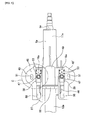
- FIG. 19 and FIG. 20 illustrate an example of the construction of a section that supports the steering column 6a with respect to the vehicle body that differs from the construction disclosed in the patent literature 1 to 4, however has been generally known.
- the middle section of the steering column 6a is supported by a support bracket 18 via a tilting rod 19, and this support bracket 18 is supported by the vehicle body 15 so that it drops when a large force is applied in the forward direction.
- the support bracket 18 is formed into one piece by joining and fastening together a top plate 20 and a pair of left and right side plates 21, 21' through welding or the like, the top plate 20 and the side plates 21, 21' being obtained by bending a metal plate having sufficient strength and rigidity, such as steel plate, respectively.
- the portions on both the left and right end sections of the top plate 20 that protrude further toward the left and right sides than the side plates 21, 21' function as installation plates 22 for attaching the support bracket 18 to the vehicle body 15 so that the support bracket 18 can drop down during a secondary collision.
- Cut out sections 23, which are open at the rear edge of the installation plate 22, are provided on each installation plate 22.
- Support capsules 16 are installed on the inside of each of the cut out sections 23.
- the support capsules 16 are formed by injection molding using synthetic resin, or by die cast molding using a light alloy.
- the support capsules 16 are supported by the installation plates 22 by fitting installation grooves 25, which are formed on the left and right side surfaces, with both side sections of the cut out sections 23 on part of the installation plate 22.
- Small through holes 26a that are formed in both side sections of the cut out sections 23 on part of the installation plates 22 are aligned with small through holes 26b that are formed in the support capsules 16, and the support capsules 16 are installed by injection molding or pressure fitting fastening pins (not illustrated in the figure), which are made of synthetic resin or a light alloy, into these small through holes so that they span the small through holes 26a in the installation plates 22 and the small through holes 26b in the support capsules 16.
- the support capsules 16 are supported by the installation plates 22 so that they drop down toward the rear from the installation plates 22 only when a large impact load is applied.
- the rear section of the inner column 12a on the front side and the front section of the outer column 11a on the rear side are fitted together in a telescopic shape, and by being able to be displaced in the axial direction, the steering column 6a can be extended or contracted.
- the rear section of the inner shaft 14a on the front side and the front section of the outer shaft 13a on the rear side are fitted together so that the are able to displace in the axial direction and transmit torque.
- the outer shaft 13a is supported on the inside of the outer column 11a by a bearing such as a deep groove ball bearing that is able to support both radial loads and thrust loads so it can only rotate freely.
- the steering wheel 1 is supported and fastened to a portion of the rear end section of the outer shaft 13a that protrudes further toward the rear than the opening section on the rear end of the outer column 11a.
- the front end section of the inner column 12a is supported by the vehicle body so that it can pivot up or down around a horizontal shaft 32 ( FIG. 18 ) that is inserted through the tip end section of a support arm 31 that is fastened to the reduction gear casing 30.
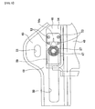
- the front section of the outer column 11a is held between the side plates 21, 21' of the support bracket 18.
- the outer column 11a is made by die cast molding using a light alloy, and a held section 33 is provided on the bottom surface of the front section thereof such that it protrudes downward.
- a slit section 34 is provided in the center section in the width direction of this held section 33, and is such that the diameter of the front section of the outer column 11a can elastically expand or contract. With the slit section 34 held, a pair of long telescopic holes 35 that are long in the axial direction of the outer column 11a are formed in the both sides of the held section 33 such that they are aligned with each other.
- long tilt holes 36a, 36b that are long in the vertical direction are formed in the side plates 21, 21' in a partial arc shape with the horizontal shaft 32 as the center and are such that they are aligned with each other. With the long tilt holes 36a, 36b and the long telescopic holes 35 crossing each other, a tilt rod 1 is inserted through these long holes.
- the tilt rod 19 is such that a pair of flat sections that are formed on part of both sides in the width direction of the outer circumferential surface of an outward facing flange shaped rim section 37 that is provided on the base end section (right end in FIG. 20 ) engages with the edge on the side of the long tilt hole 36a. Therefore, the tilt rod 19 does not rotate around its own center axis, however, it can be freely raised or lowered along the long tilt holes 36a, 36b. Moreover, the outer column 11a can displace in the forward or backward direction with respect to the support bracket 18 on which the tilt rod is placed, within a range in which the tilt rod 19 can displace inside the long telescopic holes 36 on both sides.
- the other cam plate element 42b is engaged to the base end section of the adjustment lever 40 so that relative displacement with respect to this base end section is prevented, this cam plate element 42b rotates as the adjustment lever 40 pivots, and by engaging with the other cam plate element 42a, the thickness in the axial direction of the cam mechanism 41 is expanded or reduced.
- the support bracket 18 When this kind of steering apparatus is installed in a vehicle body, the support bracket 18 is supported by the vehicle body by bolts or studs that are inserted through holes 43 that are formed in the support capsules 16.
- the thickness in the axial direction of the cam mechanism 41 is reduced by pivoting the adjustment lever 40 in a specified direction.
- the space between the pair of side plates 21, 21' of the support bracket 18 expands, and the diameter of the outer column 11a expands. In this state, it is possible to adjust the vertical position of the steering wheel 1 within a range in which the tilt rod 19 can displace along the long tilt holes 36a, 36b.
- patent literature 5 being the closest prior art document, discloses construction in which, by inserting an impact absorbing member that is provided on the steering column side in the front and rear direction thereof between members that are fastened to the vehicle body, dropping of the steering column in the downward direction can be prevented even though the steering wheel is displaced in the forward direction due to a secondary collision.
- this kind of construction in the state after a secondary collision, the steering column is suspended by way of the impact absorbing member, so construction is complex, and not only does the height dimension (dimension in the vertical direction) of the steering column increase, but after a secondary collision, it is feasible that the supporting rigidity of the steering column will be considerably less than in the normal state.
- Patent literature 6 discloses construction in which, by way of a slider provided on the steering column side and a guide rail provided on the vehicle body side, the steering column is suspended such that it can slide in the axial direction. With this kind of construction as well, it is possible to prevent the steering column from dropping down after a secondary collision. However, the construction disclosed in patent literature 6 is even more complex than the construction disclosed in patent literature 5, and it is feasible that the height dimension of the steering column will increase. Moreover, when a force is applied in a direction causing the steering column to tilt, it is possible that the same problem will occur as in the construction disclosed in patent literature 5.
- Patent Literature 1 Japanese Patent Application Publication No. 2004-182216
- Patent Literature 2 Japanese Patent Application Publication No. 2004-338509
- Patent Literature 3 Japanese Patent Application Publication No. 2005-53349
- Patent Literature 4 Japanese Patent Application Publication No. 2005-96731
- Patent Literature 5 Japanese Patent Application Publication No. 2005-280654
- Patent Literature 6 Japanese Patent Application Publication No. 2006-192971
- a steering column support apparatus having construction that is capable of suppressing an increase in the height dimension and maintaining the function of smooth forward displacement of the steering column during a secondary collision, as well as is capable of preventing the steering column from dropping down even when the steering column is displaced forward together with the steering wheel due to a secondary collision.
- the steering column support apparatus of the present invention comprises a non-dropping bracket, a dropping bracket, a pair of connection members and a pair of support capsules.
- the non-dropping bracket is fastened to and supported by the vehicle body and is located on the upper part of the middle section in the axial direction of the steering column, and comprises a top plate and a pair of long holes.
- the top plate is provided in the axial direction of the steering column.
- the long holes are formed in part of that top plate such that the holes are parallel to each other and extend in the axial direction of the steering column.
- the dropping bracket is supported by the middle section in the axial direction of the steering column.
- This dropping bracket comprises a bottom plate and a pair of installation holes.
- the bottom plate is provided such that top surface faces the bottom surface of the top plate.
- the installation holes are formed in part of the bottom plate in locations that are aligned with the rear end sections of the long holes.
- the support capsules are fastened to the non-dropping bracket in the rear end sections of the long holes in the non-dropping bracket, and are capable of displacing in the forward direction along the long holes due to an impact load in the forward direction that is applied to these support capsules. Therefore, for example, fastening pins that can be sheared off by an impact load in the shear direction span fastening holes that are formed in the support capsule and top plate in alignment with each other.
- the support capsules are such that they do not come out from the long holes in the thickness direction (vertical direction) of the top plate.
- the dropping bracket is connected to the support capsules by inserting the connection members through the installation holes and through holes that penetrate through the support capsules in the vertical direction.
- the support capsules comprise: a guide section having a width dimension that is a little less than the width dimension of the long holes, and that engages with the long holes so that the support capsules can displace in the forward or backward direction; and a rim section that has a width that is greater than the width of the long holes.
- connection member can comprise a bolt that is inserted from top to bottom through the through hole and installation hole, and a nut that is located on the bottom surface of the bottom plate that screws onto the bolt.
- connection member can comprise a stud that is inserted from bottom to top through the installation hole and through hole, the bottom end section thereof being supported by the bottom surface of the bottom plate, and the top end section protruding upward further than the top surface of the support capsule, and a nut that screws onto the top end section of the stud.
- connection member can comprise a connection pin that is inserted from bottom to top through the installation hole and through hole, the bottom end section thereof being supported by the bottom surface of the bottom plate, and the top end section protruding upward further than the top surface of the support capsule, and a retaining ring that is fastened to the top end section of the connection pin.
- the through hole of the support capsule can be constructed such that the cross-sectional area of the upper portion is greater than the cross-sectional area of the lower portion;
- the connection member can be a column shaped member that is formed by injection molding of synthetic resin in the installation hole and through hole such that the column shaped member spans the installation hole and through hole; and an outward facing flange second rim section can be formed on the bottom end section of the column shaped member in the portion that protrudes further downward than the bottom surface of the bottom plate, such that the top plate is held between this second flange section and the portion on the top end section of the column shaped member that is inside the upper portion of the through hole.
- the support capsules are made of a light alloy such as an aluminum alloy
- the fastening pins are made of a light alloy or a synthetic resin.
- Light alloy fastening pins can be mounted inside the fastening holes by driving pin shaped members into the fastening holes.
- Synthetic resin fastening pins can be mounted inside the fastening holes by injection molding of a thermoplastic synthetic resin in each of the fastening holes.
- the support capsules are made of a synthetic resin.
- the support capsules are injection molded together with the fastening pins.
- the portion of the top plate of the non-dropping bracket that is near the rear end section of the long holes, and the bottom plate of the dropping bracket are set inside an injection molding cavity, after which synthetic resin is fed into this cavity and insert molding is performed.
- the steering column support apparatus of the present invention constructed as described above, is able to suppress an increase in the height dimension, maintain a function of the steering column being able to displace smoothly in the forward direction during a secondary collision and prevent the steering column from dropping down even when the steering column is displaced together with the steering wheel in the forward direction due to a secondary collision.
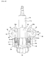
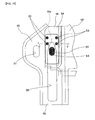
- FIG. 1 to FIG. 10 illustrate a first embodiment of the present invention.
- a feature of the present invention is construction that makes possible forward displacement of an outer column 11a of a steering column 6a with respect to a vehicle body due to a forward impact load during a secondary collision, and that supports the steering column 6a in a state able to prevent the steering column 6a from dropping downward even after forward displacement.
- the construction and function of other parts of the steering apparatus are the same as in the conventional construction explained using FIG. 18 to FIG. 20 , so the same reference numbers are given to identical parts and any redundant explanation is simplified or omitted, with the explanation below centering on the characteristic features of this embodiment.
- the support apparatus for a steering column of this embodiment comprises: a non-dropping bracket 45, a dropping bracket 46, a pair of bolts 47 as connection members, and a pair of support capsules 16a.
- the non-dropping bracket 45 is formed by pressing metal plate, such as steel plate, having sufficient strength and rigidity, and comprises a pair of left and right top plates 48, 48' and a connection plate 49 that connects the rear half sections of the top plates 48, 48' together. The edges around these top plates 48, 48' are bent downward, and together with the top plates 48, 48' having a high section modulus, sufficient bending rigidity is maintained.
- One long hole 50 and one through hole 51 are formed in each top plate 48, 48'. In other words, a pair of long holes 50 and a pair of through holes 51 are provided in the left and right top plates 48, 48'.
- the non-dropping bracket 45 is located at the top of the middle section in the axial direction of the steering column 6a, and is fastened to and supported by the vehicle body in the portion underneath the dashboard by a bolt or stud (not illustrated in the figures) that is inserted through the through hole 51.
- a bolt or stud (not illustrated in the figures) that is inserted through the through hole 51.
- the top plates 48, 48' protrude from the left and right sides of the steering column 6a, and are arranged in the axial direction of the steering column 6a.
- the long holes 50 are located on both the left and right sides of the steering column 6a, and being parallel to each other, extend from a portion near the rear end section of the center portion toward the front end section.
- the long holes 50 are formed as closed holes on the inside of the top plate 48, however, due to processing conditions, the edge on the end of the top plate 48 and the long holes 50 can be connected by a thin groove, and the long holes 50 can, for example, be formed as open holes on the front side of the top plate 48.
- a fastening pin section (not illustrated in the figures) that protrudes from the side surface of the reduction gear casing 30 to the rear in FIG. 1 fits in a fastening hole 29 that is formed on a fastening plate 28 that is provided on the tip end section of a connecting arm section 27 that extends forward from the front end section of one of the top plates 48.
- the outer column 11a is such that it cannot come apart from the inner column 12a even when the adjustment lever 40 is in a loosened state.
- the support capsules 16a are located at the rear end section of the long holes 50 so that forward displacement along the long holes 50 due to an impact load in the forward direction that is applied to the support capsules 16a is possible. Therefore, in this embodiment, fastening pins 53 that can be sheared off by an impact load in the shear direction span fastening holes 52a and fastening holes 52b that are formed in the support capsule 16 and top plate 48 in alignment with each other, and further span the fastening holes 52a of the support capsule 16a and concave sections 62 that are formed in the top plate 48 on both sides in the width direction of the rear end section of the long hole 50.
- these fastening pins 53 are made of synthetic resin, and with the fastening holes 52a and the fastening holes 52b as well as the fastening holes 52a and the concave sections 62 being aligned with each other, can be formed by injection molding in which thermoplastic resin is injected into the fastening holes 52a, 52b and concave sections 62 and hardened. Moreover, fastening pins 53 that are formed beforehand can be fitted by pressing the fastening pins 53 between the fastening holes 52a and fastening holes 52b, and between the fastening holes 52a and the concave sections 62.
- the dropping bracket 46 corresponds to the support bracket 18 that was installed in the conventional construction ( FIG. 19 and FIG. 20 ) and is formed by joining and fastening a plurality of members, which have been formed by bending metal plate, such as steel plate, having sufficient strength and rigidity, by spot welding or the like.
- the bracket 46 comprises a pair of bottom plates 54 and side plates 21a on both the left and right, and a pair of installation holes 55 that are formed in these bottom plates 54. These bottom plates 54 are connected so that they cannot be separated by a connection section 56 that is provided further on the front side section than the connection plate 49 of the non-dropping bracket 45.
- This kind of dropping bracket 46 is supported by the front end section of the outer column 11a of the steering column 6a in the middle section in the axial direction of the steering column 6a.
- the dropping bracket 46 in order to construct a tilting mechanism and telescoping mechanism for adjusting the vertical position and forward/backward position of the steering wheel ( FIG. 18 ), the dropping bracket 46 is supported by the front end section of the outer column 11a such that the vertical position and forward/backward position can be adjusted as in the conventional construction illustrated in FIG. 19 and FIG. 20 .
- the bottom plate 54 protrudes further to both the left and right sides than the steering column 6a. Moreover, with the top surfaces of the bottom plate 54 facing the bottom surface of the top plate 48 of the non-dropping bracket 45, the bottom plate 54 is connected to the top plate 48 by way of the support capsules 16a and bolts 47.
- a nut 57 is fitted and supported in the opening section on the bottom side of the installation hole 55, and the bolt 47 that is inserted from the top to the bottom through the through hole 43a in the capsule 16a and installation hole 55 is screwed into the nut 57 and tightened.
- the positions of the installation holes 55 in the dropping bracket 46 and the positions of the bolts 47 that are inserted in this installation holes 55 are preferably in nearly a straight line in the width direction of the vehicle with the position of the through holes 51 for fastening the non-dropping bracket 45 to the vehicle body by way of bolts or the like. This construction improves the rigidity of the installation of the steering column 6a to the vehicle body.
- the support capsules 16a are such that they do not come out from the long holes 50 in the vertical direction, which is the thickness direction of the top plate 48.
- the width dimension in the left and right direction of the support capsules 16a is wide in the upper half and narrow in the lower half.
- the width dimension of the lower half of the support capsule 16a is a little less than the width dimension of the long hole 50, and this lower half functions as a guide section 58 that fits in the long hole 50 so that it can displace in the forward and backward direction of the long hole 50.
- the upper half of the support capsule 16a functions as a rim section 59 having a width dimension that is greater than the width dimension of the long hole 50.
- the height dimension h of the guide section 58 illustrated in FIG. 7 and FIG. 8 is a little greater than the thickness dimension t of the top plate 48 (h > t). Also, the rear end section of the rim section 59 protrudes further to the rear than the guide section 58. Part of the fastening hole 52a provided in each support capsule 16a is formed in the portion of the rear end section of the rim section 59 that protrudes further to the rear than the guide section 58.
- the rim sections 59 and bottom plate 54 lie on portions of the top plate 48 located on the both sides of the long holes 50 and sandwich the portions in the thickness direction of the top plate 48.
- the support capsules 16a displace in the forward direction along the long holes 50, however, are in a state such that they do not come out of the long holes 50 in the thickness direction of the top plate 48.
- the dropping bracket 46 displaces in the forward direction with respect to the non-dropping bracket 45 from the state illustrated in FIG. 1 and FIG. 2 to the state illustrated in FIG. 9 and FIG. 10 .
- the support capsules 16a only displace in the forward direction along the long holes 50 and do not come out in either the downward or upward direction of the top plate 48. Therefore, even after the steering column 6a has absorbed the impact energy that is applied to the steering wheel 1 from the driver's body due to a secondary collision and displaces in the forward direction, the position of the height of the steering wheel 1 remains in a position such that it is easy to steer. Therefore, after a collision accident, the work of moving the vehicle out of the way and to the shoulder of the road under its own power or by pushing can be performed easily.
- the amount that the steering column 6a protrudes from underneath the dashboard can be kept to a minimum. Therefore, in addition to being able to increase the freedom of design for preventing interference between the steering column 6a and the driver's knees, it becomes easier to perform design for preventing injury to the driver due to the steering column 6a hitting the driver's knees during a collision accident.
- each of the long holes 5 and support capsules 16a are located at positions on both the left and right sides of the steering column 6a, so it is possible to maintain support rigidity of the steering column 6a with respect to the force applied in a direction that causes the steering column 6a to tilt such as during a secondary collision. Therefore, during a secondary collision, displacement of the steering column 6a in the forward direction can be performed stably and reliably, and thus it is possible to completely protect the driver.
- the support capsules 16a are installed so that during a secondary collision they displace in the forward direction in the pair of long holes 50 that are provided in the top plate 48.
- the support capsules 16a are not used in order to support the non-dropping bracket 45, which comprises the top plate 48, with respect to the vehicle body. Therefore, it is possible to make these support capsules 16a more compact than in the case of the conventional construction illustrated in FIG. 19 and FIG. 20 .
- the through holes 51 through which the bolts or the like are inserted for attaching the non-dropping bracket 45 to the vehicle body are provided separately from the long holes 50.
- these through holes 51 does not limit the amount of displacement of the outer column 11a in the forward direction during a secondary collision. It is also possible to sufficiently increase the freedom of the location for these through holes 51.
- the fastening pins 53 are located further to the rear than the bolts 47 that connect the non-dropping bracket 45 and the dropping bracket 46. Therefore, even when a force is applied at an angle to the outer column 11a during a secondary collision, the bolts 47 can effectively apply a tensile force from the bolts 47 to the support capsules 16a that pull the support capsules 16a in the forward direction. As a result, a shearing force is applied to the fastening pins 53, and the outer column 11a is caused to displace in the forward direction.
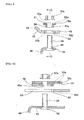
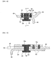
- FIG. 11 and FIG. 12 illustrate a second embodiment of the present invention.
- studs 24 are used as the connection members for connecting and fastening the dropping bracket 46 to the support capsules 16a.
- the bottom end section of this stud 24 is fastened to and supported by the installation hole 55 section of the bottom plate section 54 of the dropping bracket 46, with the stud 24 being inserted through this installation hole 55 from the bottom to the top.
- the stud 24 being inserted through the through hole 43a in the support capsule 16a from the bottom to the top, the portion on the top end section of the stud 24 that protrudes upward further than the top surface of the support capsule 16a is screwed into a nut 57a and tightened.
- the construction and function of other parts are the same as in the case of the first embodiment, so drawings and explanations of identical parts are omitted.
- FIG. 13 and FIG. 14 illustrate a third embodiment of the present invention.
- connection pins 60 are used as the connection members for connecting and fastening the dropping bracket 46 to the support capsules 16a.
- a retaining ring 61 is fastened to the portion on the top end section of the connection pin 60 that protrudes upward further than the top surface of the support capsule 16a.
- this embodiment is the same as the second embodiment, so any redundant explanation is omitted.
- FIG. 15 to FIG. 17 illustrate a fourth embodiment of the present invention.
- synthetic resin column shaped members 63 are used as the connection members for connecting and fastening the dropping bracket 46 to the support capsules 16a.
- This column shaped member 63 is formed by performing injection molding inside the installation hole 55 that is formed in the bottom plate 54 of the dropping bracket 46 and the through hole 43a in the support capsule 16a such that the connection member spans between the installation hole 55 and the through hole 43a.
- the cross-sectional area of the portion on the upper side of the through hole is greater than the cross-sectional area of the portion on the lower side, and forms an outward facing flange shaped second rim section 64 in the portion on the lower end section of the column shaped member 63 that protrudes further than the bottom surface of the bottom plate 54.
- the top side and bottom side of the top plate 48 of the non-dropping bracket 45 are held between this second rim section 64 and the top section of the column shaped member 63 that is inside the upper portion of the through hole 43a.
- the support capsule 16a was made of a light alloy, and the fastening pins 53 and column shaped member 63 are made of a synthetic resin.
- the support capsule 16a it is possible for the support capsule 16a to be made of a synthetic resin, and to integrate the support capsule 16a, the fastening pins 53 and the column shaped member 63.
- the support capsule 16a is formed by injection molding (insert molding) together with the fastening pins 53 and column shaped member 63.
- the shape after completion is the same as that illustrated in FIG. 15 to FIG. 17 except that the support capsule 16a, the fastening pins 53 and the column shaped member 63 are integrated.
- the intent of the present invention is to keep the position of the steering wheel from becoming unstable even in a state after the steering wheel has displaced in the forward direction due to a secondary collision. Therefore, as illustrated in the figures, without being limited to a tilting and telescoping mechanism, the present invention can be applied to a steering apparatus that comprises just a tilting mechanism or just a telescoping mechanism, and furthermore can be applied to a steering apparatus that does not comprise either of these.
Landscapes
- Engineering & Computer Science (AREA)
- Chemical & Material Sciences (AREA)
- Combustion & Propulsion (AREA)
- Transportation (AREA)
- Mechanical Engineering (AREA)
- Steering Controls (AREA)
- Body Structure For Vehicles (AREA)
Applications Claiming Priority (2)
| Application Number | Priority Date | Filing Date | Title |
|---|---|---|---|
| JP2010137584 | 2010-06-16 | ||
| PCT/JP2011/063501 WO2011158787A1 (ja) | 2010-06-16 | 2011-06-13 | ステアリングコラムの支持装置 |
Publications (3)
| Publication Number | Publication Date |
|---|---|
| EP2565103A1 EP2565103A1 (en) | 2013-03-06 |
| EP2565103A4 EP2565103A4 (en) | 2013-10-16 |
| EP2565103B1 true EP2565103B1 (en) | 2015-04-01 |
Family
ID=45348186
Family Applications (1)
| Application Number | Title | Priority Date | Filing Date |
|---|---|---|---|
| EP11740803.9A Active EP2565103B1 (en) | 2010-06-16 | 2011-06-13 | Steering column support device |
Country Status (5)
| Country | Link |
|---|---|
| US (1) | US8562020B2 (zh) |
| EP (1) | EP2565103B1 (zh) |
| JP (1) | JP5429295B2 (zh) |
| CN (1) | CN102481945B (zh) |
| WO (1) | WO2011158787A1 (zh) |
Families Citing this family (39)
| Publication number | Priority date | Publication date | Assignee | Title |
|---|---|---|---|---|
| JP5499995B2 (ja) * | 2010-08-26 | 2014-05-21 | 日本精工株式会社 | 電動式パワーステアリング装置を備えた衝撃吸収式ステアリング装置 |
| WO2012053319A1 (ja) * | 2010-10-22 | 2012-04-26 | 日本精工株式会社 | ステアリングコラム用支持装置およびその組立方法 |
| US8534705B2 (en) * | 2010-12-21 | 2013-09-17 | Nsk Ltd. | Steering column support apparatus |
| EP2700560B1 (en) * | 2011-04-22 | 2016-04-06 | NSK Ltd. | Support device for steering column and method for manufacturing same |
| JP5949281B2 (ja) * | 2012-07-27 | 2016-07-06 | 株式会社ジェイテクト | 車両用ステアリング装置 |
| CN103732472B (zh) * | 2012-08-09 | 2016-11-09 | 日本精工株式会社 | 倾斜式转向柱装置 |
| US8777264B2 (en) * | 2012-10-05 | 2014-07-15 | GM Global Technology Operations LLC | Steering column assembly for a motor vehicle |
| JP5846321B2 (ja) * | 2013-01-22 | 2016-01-20 | 日本精工株式会社 | チルト式ステアリング装置 |
| JP6150333B2 (ja) | 2013-01-30 | 2017-06-21 | 株式会社ジェイテクト | ステアリング装置 |
| JP6021107B2 (ja) * | 2013-01-30 | 2016-11-02 | 株式会社ジェイテクト | ステアリングコラム装置 |
| JP5971725B2 (ja) | 2013-01-30 | 2016-08-17 | 株式会社ジェイテクト | ステアリングコラム装置 |
| JP2014189154A (ja) * | 2013-03-27 | 2014-10-06 | Showa Corp | ステアリング装置 |
| KR101987154B1 (ko) * | 2013-04-18 | 2019-06-10 | 현대자동차 주식회사 | 자동차의 조향장치 |
| KR101493151B1 (ko) * | 2013-05-02 | 2015-02-23 | 주식회사 만도 | 차량의 스티어링 장치 |
| JP6115769B2 (ja) * | 2013-05-24 | 2017-04-19 | 株式会社ジェイテクト | ステアリング装置 |
| JP6176654B2 (ja) * | 2013-06-11 | 2017-08-09 | 株式会社ジェイテクト | ステアリング装置 |
| WO2014199226A2 (ja) * | 2013-06-11 | 2014-12-18 | 株式会社ジェイテクト | ステアリング装置 |
| JP6239875B2 (ja) * | 2013-06-28 | 2017-11-29 | 株式会社ジェイテクト | ステアリング装置 |
| JP6103536B2 (ja) * | 2013-07-18 | 2017-03-29 | 株式会社ジェイテクト | ステアリング装置 |
| JP5856204B2 (ja) * | 2014-02-19 | 2016-02-09 | 株式会社山田製作所 | ステアリング装置 |
| DE102014104350B3 (de) * | 2014-03-28 | 2015-05-13 | Thyssenkrupp Presta Ag | Lenksäule für ein Kraftfahrzeug |
| JP6413375B2 (ja) * | 2014-06-13 | 2018-10-31 | 日本精工株式会社 | チルト式ステアリング装置 |
| CN104002854A (zh) * | 2014-06-16 | 2014-08-27 | 奇瑞汽车股份有限公司 | 一种吸能汽车转向管柱总成 |
| KR101575337B1 (ko) | 2014-06-20 | 2015-12-07 | 현대자동차 주식회사 | 차량용 스티어링 컬럼 마운팅 유닛 |
| JP6350022B2 (ja) * | 2014-06-26 | 2018-07-04 | 日本精工株式会社 | チルト式ステアリング装置 |
| JP6365041B2 (ja) * | 2014-07-11 | 2018-08-01 | 日本精工株式会社 | チルト式ステアリング装置 |
| KR101602182B1 (ko) * | 2014-12-18 | 2016-03-11 | 주식회사 만도 | 자동차의 조향 컬럼 |
| US9849906B2 (en) * | 2015-03-27 | 2017-12-26 | Fuji Kiko Co., Ltd. | Steering column device |
| WO2016186144A1 (ja) * | 2015-05-19 | 2016-11-24 | 日本精工株式会社 | テレスコピック式ステアリング装置 |
| US10059363B2 (en) * | 2015-05-19 | 2018-08-28 | Nsk Ltd. | Steering device |
| CN107614355B (zh) * | 2015-05-19 | 2018-12-28 | 日本精工株式会社 | 转向装置 |
| CN105752150A (zh) * | 2016-02-24 | 2016-07-13 | 北京汽车研究总院有限公司 | 一种转向管柱装置和汽车 |
| JP6609211B2 (ja) * | 2016-03-28 | 2019-11-20 | 富士機工株式会社 | ステアリングコラム装置 |
| JP6598724B2 (ja) * | 2016-04-07 | 2019-10-30 | 株式会社ジェイテクト | ステアリング装置 |
| JP6701519B2 (ja) * | 2016-04-27 | 2020-05-27 | 株式会社ジェイテクト | ステアリング装置 |
| GB201705272D0 (en) * | 2016-07-07 | 2017-05-17 | Trw Steering Systems Poland Sp Z O O | A steering column assembly |
| CN107458450B (zh) * | 2017-08-08 | 2020-05-19 | 上海蒂森克虏伯汇众汽车零部件有限公司 | 导向套筒支架 |
| CN111918809B (zh) * | 2018-03-27 | 2022-09-20 | 日本精工株式会社 | 转向装置 |
| CN116534113B (zh) * | 2023-05-22 | 2023-11-24 | 浙江永励精密制造股份有限公司 | 一种转向管柱总成及车辆 |
Family Cites Families (36)
| Publication number | Priority date | Publication date | Assignee | Title |
|---|---|---|---|---|
| US3740068A (en) * | 1970-02-07 | 1973-06-19 | Toyota Motor Co Ltd | Steering column support assembly |
| JPS5216129U (zh) * | 1975-07-21 | 1977-02-04 | ||
| US4194411A (en) * | 1977-04-06 | 1980-03-25 | Koyo Seiko Company Limited | Steering column support assembly |
| JPS5886764U (ja) * | 1981-12-03 | 1983-06-13 | 日本精工株式会社 | 衝撃吸収ステアリング装置 |
| JPS5991961U (ja) * | 1982-12-13 | 1984-06-22 | トヨタ自動車株式会社 | ステアリングコラムの支持構造 |
| JPS6020460U (ja) * | 1983-07-20 | 1985-02-13 | トヨタ自動車株式会社 | エネルギ吸収ステアリング装置 |
| JPH057902Y2 (zh) * | 1986-03-24 | 1993-02-26 | ||
| JPH059272Y2 (zh) * | 1986-03-25 | 1993-03-08 | ||
| JPH08216Y2 (ja) * | 1988-07-25 | 1996-01-10 | 日産自動車株式会社 | エネルギー吸収式ステアリングコラム |
| JPH04186059A (ja) | 1990-11-16 | 1992-07-02 | Matsushita Electric Ind Co Ltd | 温水ボイラー等の安全装置 |
| JPH05216129A (ja) | 1992-02-03 | 1993-08-27 | Canon Inc | マイクロフィルムリーダースキャナー |
| JPH0620460A (ja) | 1992-07-02 | 1994-01-28 | Fujitsu Ltd | 情報記憶モジュール及びディスクエンクロージャ交換方法 |
| JP2670531B2 (ja) | 1993-02-19 | 1997-10-29 | 株式会社協和 | 背負い帯 |
| JPH08150943A (ja) * | 1994-11-30 | 1996-06-11 | Fuji Kiko Co Ltd | チルトステアリングコラム |
| US5899116A (en) * | 1997-12-08 | 1999-05-04 | General Motors Corporation | Connection for energy-absorbing steering column |
| JP3468711B2 (ja) * | 1999-02-18 | 2003-11-17 | 株式会社山田製作所 | ステアリングコラムの衝撃吸収装置 |
| JP4667676B2 (ja) * | 2000-09-19 | 2011-04-13 | エヌエスケー ステアリング システムズ ヨーロッパ リミテッド | 車両のステアリングコラム制御装置 |
| US6394494B1 (en) * | 2000-09-20 | 2002-05-28 | Daimlerchrysler Corporation | Steering column having a magnesium upper mounting bracket release break-away bar |
| US6655715B2 (en) * | 2001-06-27 | 2003-12-02 | Delphi Technologies, Inc. | Mounting apparatus for motor vehicle steering column |
| JP3738200B2 (ja) * | 2001-06-27 | 2006-01-25 | 光洋精工株式会社 | 衝撃吸収ステアリング装置 |
| JP4126955B2 (ja) * | 2002-05-08 | 2008-07-30 | 日本精工株式会社 | 衝撃吸収式ステアリングコラム装置 |
| JP4124021B2 (ja) | 2002-10-07 | 2008-07-23 | トヨタ自動車株式会社 | 衝撃吸収式ステアリングコラム装置 |
| JP4193630B2 (ja) | 2003-08-05 | 2008-12-10 | トヨタ自動車株式会社 | 衝撃吸収式ステアリングコラム装置 |
| JP2004338509A (ja) | 2003-05-14 | 2004-12-02 | Toyota Motor Corp | 衝撃吸収式ステアリングコラム装置 |
| JP4207799B2 (ja) | 2003-09-02 | 2009-01-14 | トヨタ自動車株式会社 | 衝撃吸収式ステアリングコラム装置 |
| JP4186059B2 (ja) | 2003-06-10 | 2008-11-26 | トヨタ自動車株式会社 | 衝撃吸収式ステアリングコラム装置 |
| JP2005280654A (ja) * | 2004-03-31 | 2005-10-13 | Fuji Kiko Co Ltd | 衝撃吸収式ステアリング装置 |
| JP2005343331A (ja) | 2004-06-03 | 2005-12-15 | Nsk Ltd | 車両用ステアリング装置 |
| JP2006192971A (ja) | 2005-01-11 | 2006-07-27 | Toyota Motor Corp | 衝撃吸収式ステアリングコラム装置 |
| JP5034490B2 (ja) * | 2006-12-26 | 2012-09-26 | 日本精工株式会社 | 衝撃吸収式ステアリングコラム装置 |
| JP2008265647A (ja) | 2007-04-24 | 2008-11-06 | Nsk Ltd | 位置調整式ステアリング装置 |
| JP4831359B2 (ja) | 2007-06-15 | 2011-12-07 | 三菱自動車工業株式会社 | ステアリングコラム装置の衝撃吸収構造 |
| JP5181668B2 (ja) | 2007-12-27 | 2013-04-10 | 日本精工株式会社 | ステアリング装置 |
| JP4985443B2 (ja) | 2008-02-12 | 2012-07-25 | トヨタ自動車株式会社 | ステアリングコラム装置 |
| JP5167995B2 (ja) * | 2008-07-11 | 2013-03-21 | 日本精工株式会社 | ステアリング装置 |
| JP5216129B2 (ja) | 2011-09-06 | 2013-06-19 | キヤノン株式会社 | 画像形成装置 |
-
2011
- 2011-06-13 US US13/201,348 patent/US8562020B2/en active Active
- 2011-06-13 WO PCT/JP2011/063501 patent/WO2011158787A1/ja active Application Filing
- 2011-06-13 EP EP11740803.9A patent/EP2565103B1/en active Active
- 2011-06-13 CN CN201180000898.7A patent/CN102481945B/zh active Active
- 2011-06-13 JP JP2011533899A patent/JP5429295B2/ja active Active
Also Published As
| Publication number | Publication date |
|---|---|
| JPWO2011158787A1 (ja) | 2013-08-19 |
| EP2565103A4 (en) | 2013-10-16 |
| US8562020B2 (en) | 2013-10-22 |
| CN102481945B (zh) | 2014-07-02 |
| US20120112443A1 (en) | 2012-05-10 |
| EP2565103A1 (en) | 2013-03-06 |
| JP5429295B2 (ja) | 2014-02-26 |
| WO2011158787A1 (ja) | 2011-12-22 |
| CN102481945A (zh) | 2012-05-30 |
Similar Documents
| Publication | Publication Date | Title |
|---|---|---|
| EP2565103B1 (en) | Steering column support device | |
| EP2535239B1 (en) | Steering apparatus | |
| JP5614449B2 (ja) | 自動車用ステアリング装置 | |
| US8733793B2 (en) | Steering column support apparatus | |
| EP2716521B1 (en) | Steering device | |
| US9114828B2 (en) | Telescopic steering apparatus | |
| EP2628655B1 (en) | Automobile steering device | |
| EP2765058B1 (en) | Steering column device | |
| EP2641812B1 (en) | Support device for steering column | |
| JP6020186B2 (ja) | ステアリングコラム用支持装置 | |
| JP5553005B2 (ja) | ステアリングコラム用支持装置 | |
| JP5327181B2 (ja) | 自動車用ステアリング装置 | |
| JP2014136501A (ja) | ステアリングコラム用支持装置 | |
| JP5327193B2 (ja) | ステアリングコラム用支持装置 | |
| JP5375806B2 (ja) | ステアリングコラム用支持装置及びステアリングコラム用支持装置用係止カプセルの製造方法 | |
| JP5327186B2 (ja) | ステアリングコラム用支持装置 |
Legal Events
| Date | Code | Title | Description |
|---|---|---|---|
| PUAI | Public reference made under article 153(3) epc to a published international application that has entered the european phase |
Free format text: ORIGINAL CODE: 0009012 |
|
| 17P | Request for examination filed |
Effective date: 20110811 |
|
| AK | Designated contracting states |
Kind code of ref document: A1 Designated state(s): AL AT BE BG CH CY CZ DE DK EE ES FI FR GB GR HR HU IE IS IT LI LT LU LV MC MK MT NL NO PL PT RO RS SE SI SK SM TR |
|
| R17P | Request for examination filed (corrected) |
Effective date: 20110811 |
|
| DAX | Request for extension of the european patent (deleted) | ||
| A4 | Supplementary search report drawn up and despatched |
Effective date: 20130918 |
|
| RIC1 | Information provided on ipc code assigned before grant |
Ipc: B62D 1/19 20060101AFI20130912BHEP Ipc: B60R 21/05 20060101ALI20130912BHEP |
|
| GRAP | Despatch of communication of intention to grant a patent |
Free format text: ORIGINAL CODE: EPIDOSNIGR1 |
|
| INTG | Intention to grant announced |
Effective date: 20141027 |
|
| GRAS | Grant fee paid |
Free format text: ORIGINAL CODE: EPIDOSNIGR3 |
|
| GRAA | (expected) grant |
Free format text: ORIGINAL CODE: 0009210 |
|
| AK | Designated contracting states |
Kind code of ref document: B1 Designated state(s): AL AT BE BG CH CY CZ DE DK EE ES FI FR GB GR HR HU IE IS IT LI LT LU LV MC MK MT NL NO PL PT RO RS SE SI SK SM TR |
|
| REG | Reference to a national code |
Ref country code: GB Ref legal event code: FG4D |
|
| REG | Reference to a national code |
Ref country code: CH Ref legal event code: EP |
|
| REG | Reference to a national code |
Ref country code: IE Ref legal event code: FG4D |
|
| REG | Reference to a national code |
Ref country code: DE Ref legal event code: R096 Ref document number: 602011015262 Country of ref document: DE Effective date: 20150513 |
|
| REG | Reference to a national code |
Ref country code: AT Ref legal event code: REF Ref document number: 718893 Country of ref document: AT Kind code of ref document: T Effective date: 20150515 |
|
| REG | Reference to a national code |
Ref country code: NL Ref legal event code: VDEP Effective date: 20150401 |
|
| REG | Reference to a national code |
Ref country code: AT Ref legal event code: MK05 Ref document number: 718893 Country of ref document: AT Kind code of ref document: T Effective date: 20150401 |
|
| REG | Reference to a national code |
Ref country code: LT Ref legal event code: MG4D |
|
| PG25 | Lapsed in a contracting state [announced via postgrant information from national office to epo] |
Ref country code: NL Free format text: LAPSE BECAUSE OF FAILURE TO SUBMIT A TRANSLATION OF THE DESCRIPTION OR TO PAY THE FEE WITHIN THE PRESCRIBED TIME-LIMIT Effective date: 20150401 |
|
| PG25 | Lapsed in a contracting state [announced via postgrant information from national office to epo] |
Ref country code: NO Free format text: LAPSE BECAUSE OF FAILURE TO SUBMIT A TRANSLATION OF THE DESCRIPTION OR TO PAY THE FEE WITHIN THE PRESCRIBED TIME-LIMIT Effective date: 20150701 Ref country code: FI Free format text: LAPSE BECAUSE OF FAILURE TO SUBMIT A TRANSLATION OF THE DESCRIPTION OR TO PAY THE FEE WITHIN THE PRESCRIBED TIME-LIMIT Effective date: 20150401 Ref country code: PT Free format text: LAPSE BECAUSE OF FAILURE TO SUBMIT A TRANSLATION OF THE DESCRIPTION OR TO PAY THE FEE WITHIN THE PRESCRIBED TIME-LIMIT Effective date: 20150803 Ref country code: LT Free format text: LAPSE BECAUSE OF FAILURE TO SUBMIT A TRANSLATION OF THE DESCRIPTION OR TO PAY THE FEE WITHIN THE PRESCRIBED TIME-LIMIT Effective date: 20150401 Ref country code: HR Free format text: LAPSE BECAUSE OF FAILURE TO SUBMIT A TRANSLATION OF THE DESCRIPTION OR TO PAY THE FEE WITHIN THE PRESCRIBED TIME-LIMIT Effective date: 20150401 Ref country code: CZ Free format text: LAPSE BECAUSE OF FAILURE TO SUBMIT A TRANSLATION OF THE DESCRIPTION OR TO PAY THE FEE WITHIN THE PRESCRIBED TIME-LIMIT Effective date: 20150401 Ref country code: ES Free format text: LAPSE BECAUSE OF FAILURE TO SUBMIT A TRANSLATION OF THE DESCRIPTION OR TO PAY THE FEE WITHIN THE PRESCRIBED TIME-LIMIT Effective date: 20150401 |
|
| PG25 | Lapsed in a contracting state [announced via postgrant information from national office to epo] |
Ref country code: AT Free format text: LAPSE BECAUSE OF FAILURE TO SUBMIT A TRANSLATION OF THE DESCRIPTION OR TO PAY THE FEE WITHIN THE PRESCRIBED TIME-LIMIT Effective date: 20150401 Ref country code: GR Free format text: LAPSE BECAUSE OF FAILURE TO SUBMIT A TRANSLATION OF THE DESCRIPTION OR TO PAY THE FEE WITHIN THE PRESCRIBED TIME-LIMIT Effective date: 20150702 Ref country code: RS Free format text: LAPSE BECAUSE OF FAILURE TO SUBMIT A TRANSLATION OF THE DESCRIPTION OR TO PAY THE FEE WITHIN THE PRESCRIBED TIME-LIMIT Effective date: 20150401 Ref country code: LV Free format text: LAPSE BECAUSE OF FAILURE TO SUBMIT A TRANSLATION OF THE DESCRIPTION OR TO PAY THE FEE WITHIN THE PRESCRIBED TIME-LIMIT Effective date: 20150401 Ref country code: IS Free format text: LAPSE BECAUSE OF FAILURE TO SUBMIT A TRANSLATION OF THE DESCRIPTION OR TO PAY THE FEE WITHIN THE PRESCRIBED TIME-LIMIT Effective date: 20150801 |
|
| REG | Reference to a national code |
Ref country code: DE Ref legal event code: R097 Ref document number: 602011015262 Country of ref document: DE |
|
| PG25 | Lapsed in a contracting state [announced via postgrant information from national office to epo] |
Ref country code: DK Free format text: LAPSE BECAUSE OF FAILURE TO SUBMIT A TRANSLATION OF THE DESCRIPTION OR TO PAY THE FEE WITHIN THE PRESCRIBED TIME-LIMIT Effective date: 20150401 Ref country code: EE Free format text: LAPSE BECAUSE OF FAILURE TO SUBMIT A TRANSLATION OF THE DESCRIPTION OR TO PAY THE FEE WITHIN THE PRESCRIBED TIME-LIMIT Effective date: 20150401 Ref country code: IT Free format text: LAPSE BECAUSE OF FAILURE TO SUBMIT A TRANSLATION OF THE DESCRIPTION OR TO PAY THE FEE WITHIN THE PRESCRIBED TIME-LIMIT Effective date: 20150401 Ref country code: MC Free format text: LAPSE BECAUSE OF FAILURE TO SUBMIT A TRANSLATION OF THE DESCRIPTION OR TO PAY THE FEE WITHIN THE PRESCRIBED TIME-LIMIT Effective date: 20150401 |
|
| REG | Reference to a national code |
Ref country code: CH Ref legal event code: PL |
|
| PLBE | No opposition filed within time limit |
Free format text: ORIGINAL CODE: 0009261 |
|
| STAA | Information on the status of an ep patent application or granted ep patent |
Free format text: STATUS: NO OPPOSITION FILED WITHIN TIME LIMIT |
|
| PG25 | Lapsed in a contracting state [announced via postgrant information from national office to epo] |
Ref country code: LU Free format text: LAPSE BECAUSE OF FAILURE TO SUBMIT A TRANSLATION OF THE DESCRIPTION OR TO PAY THE FEE WITHIN THE PRESCRIBED TIME-LIMIT Effective date: 20150613 Ref country code: SK Free format text: LAPSE BECAUSE OF FAILURE TO SUBMIT A TRANSLATION OF THE DESCRIPTION OR TO PAY THE FEE WITHIN THE PRESCRIBED TIME-LIMIT Effective date: 20150401 Ref country code: RO Free format text: LAPSE BECAUSE OF NON-PAYMENT OF DUE FEES Effective date: 20150401 Ref country code: PL Free format text: LAPSE BECAUSE OF FAILURE TO SUBMIT A TRANSLATION OF THE DESCRIPTION OR TO PAY THE FEE WITHIN THE PRESCRIBED TIME-LIMIT Effective date: 20150401 |
|
| 26N | No opposition filed |
Effective date: 20160105 |
|
| REG | Reference to a national code |
Ref country code: IE Ref legal event code: MM4A |
|
| PG25 | Lapsed in a contracting state [announced via postgrant information from national office to epo] |
Ref country code: IE Free format text: LAPSE BECAUSE OF NON-PAYMENT OF DUE FEES Effective date: 20150613 Ref country code: CH Free format text: LAPSE BECAUSE OF NON-PAYMENT OF DUE FEES Effective date: 20150630 Ref country code: LI Free format text: LAPSE BECAUSE OF NON-PAYMENT OF DUE FEES Effective date: 20150630 |
|
| REG | Reference to a national code |
Ref country code: FR Ref legal event code: PLFP Year of fee payment: 6 |
|
| PG25 | Lapsed in a contracting state [announced via postgrant information from national office to epo] |
Ref country code: SI Free format text: LAPSE BECAUSE OF FAILURE TO SUBMIT A TRANSLATION OF THE DESCRIPTION OR TO PAY THE FEE WITHIN THE PRESCRIBED TIME-LIMIT Effective date: 20150401 |
|
| PG25 | Lapsed in a contracting state [announced via postgrant information from national office to epo] |
Ref country code: BE Free format text: LAPSE BECAUSE OF FAILURE TO SUBMIT A TRANSLATION OF THE DESCRIPTION OR TO PAY THE FEE WITHIN THE PRESCRIBED TIME-LIMIT Effective date: 20150401 |
|
| PG25 | Lapsed in a contracting state [announced via postgrant information from national office to epo] |
Ref country code: MT Free format text: LAPSE BECAUSE OF FAILURE TO SUBMIT A TRANSLATION OF THE DESCRIPTION OR TO PAY THE FEE WITHIN THE PRESCRIBED TIME-LIMIT Effective date: 20150401 |
|
| REG | Reference to a national code |
Ref country code: FR Ref legal event code: PLFP Year of fee payment: 7 |
|
| PG25 | Lapsed in a contracting state [announced via postgrant information from national office to epo] |
Ref country code: SM Free format text: LAPSE BECAUSE OF FAILURE TO SUBMIT A TRANSLATION OF THE DESCRIPTION OR TO PAY THE FEE WITHIN THE PRESCRIBED TIME-LIMIT Effective date: 20150401 Ref country code: HU Free format text: LAPSE BECAUSE OF FAILURE TO SUBMIT A TRANSLATION OF THE DESCRIPTION OR TO PAY THE FEE WITHIN THE PRESCRIBED TIME-LIMIT; INVALID AB INITIO Effective date: 20110613 Ref country code: BG Free format text: LAPSE BECAUSE OF FAILURE TO SUBMIT A TRANSLATION OF THE DESCRIPTION OR TO PAY THE FEE WITHIN THE PRESCRIBED TIME-LIMIT Effective date: 20150401 |
|
| PG25 | Lapsed in a contracting state [announced via postgrant information from national office to epo] |
Ref country code: CY Free format text: LAPSE BECAUSE OF FAILURE TO SUBMIT A TRANSLATION OF THE DESCRIPTION OR TO PAY THE FEE WITHIN THE PRESCRIBED TIME-LIMIT Effective date: 20150401 Ref country code: SE Free format text: LAPSE BECAUSE OF FAILURE TO SUBMIT A TRANSLATION OF THE DESCRIPTION OR TO PAY THE FEE WITHIN THE PRESCRIBED TIME-LIMIT Effective date: 20150401 |
|
| PG25 | Lapsed in a contracting state [announced via postgrant information from national office to epo] |
Ref country code: TR Free format text: LAPSE BECAUSE OF FAILURE TO SUBMIT A TRANSLATION OF THE DESCRIPTION OR TO PAY THE FEE WITHIN THE PRESCRIBED TIME-LIMIT Effective date: 20150401 |
|
| REG | Reference to a national code |
Ref country code: FR Ref legal event code: PLFP Year of fee payment: 8 |
|
| PG25 | Lapsed in a contracting state [announced via postgrant information from national office to epo] |
Ref country code: MK Free format text: LAPSE BECAUSE OF FAILURE TO SUBMIT A TRANSLATION OF THE DESCRIPTION OR TO PAY THE FEE WITHIN THE PRESCRIBED TIME-LIMIT Effective date: 20150401 |
|
| PG25 | Lapsed in a contracting state [announced via postgrant information from national office to epo] |
Ref country code: AL Free format text: LAPSE BECAUSE OF FAILURE TO SUBMIT A TRANSLATION OF THE DESCRIPTION OR TO PAY THE FEE WITHIN THE PRESCRIBED TIME-LIMIT Effective date: 20150401 |
|
| PGFP | Annual fee paid to national office [announced via postgrant information from national office to epo] |
Ref country code: FR Payment date: 20190510 Year of fee payment: 9 |
|
| PGFP | Annual fee paid to national office [announced via postgrant information from national office to epo] |
Ref country code: GB Payment date: 20190612 Year of fee payment: 9 |
|
| GBPC | Gb: european patent ceased through non-payment of renewal fee |
Effective date: 20200613 |
|
| PG25 | Lapsed in a contracting state [announced via postgrant information from national office to epo] |
Ref country code: GB Free format text: LAPSE BECAUSE OF NON-PAYMENT OF DUE FEES Effective date: 20200613 Ref country code: FR Free format text: LAPSE BECAUSE OF NON-PAYMENT OF DUE FEES Effective date: 20200630 |
|
| PGFP | Annual fee paid to national office [announced via postgrant information from national office to epo] |
Ref country code: DE Payment date: 20230502 Year of fee payment: 13 |