EP2538111A2 - Umgekehrter Zahnketten-Ritzelantrieb mit reduzierter Eingriffswirkung - Google Patents
Umgekehrter Zahnketten-Ritzelantrieb mit reduzierter Eingriffswirkung Download PDFInfo
- Publication number
- EP2538111A2 EP2538111A2 EP12005311A EP12005311A EP2538111A2 EP 2538111 A2 EP2538111 A2 EP 2538111A2 EP 12005311 A EP12005311 A EP 12005311A EP 12005311 A EP12005311 A EP 12005311A EP 2538111 A2 EP2538111 A2 EP 2538111A2
- Authority
- EP
- European Patent Office
- Prior art keywords
- chain
- flank
- sprocket
- meshing
- contact
- Prior art date
- Legal status (The legal status is an assumption and is not a legal conclusion. Google has not performed a legal analysis and makes no representation as to the accuracy of the status listed.)
- Granted
Links
- 230000007704 transition Effects 0.000 claims description 48
- 238000013459 approach Methods 0.000 claims description 5
- 230000009467 reduction Effects 0.000 abstract description 2
- 238000011161 development Methods 0.000 description 10
- 238000006243 chemical reaction Methods 0.000 description 5
- 238000013461 design Methods 0.000 description 5
- 239000000470 constituent Substances 0.000 description 4
- 230000003247 decreasing effect Effects 0.000 description 4
- 238000006073 displacement reaction Methods 0.000 description 4
- 210000003371 toe Anatomy 0.000 description 4
- 230000007423 decrease Effects 0.000 description 3
- 230000004075 alteration Effects 0.000 description 2
- 230000008901 benefit Effects 0.000 description 2
- 238000004519 manufacturing process Methods 0.000 description 2
- 238000000034 method Methods 0.000 description 2
- 238000012986 modification Methods 0.000 description 2
- 230000004048 modification Effects 0.000 description 2
- 230000008569 process Effects 0.000 description 2
- 238000011144 upstream manufacturing Methods 0.000 description 2
- 230000009471 action Effects 0.000 description 1
- 230000002411 adverse Effects 0.000 description 1
- 150000001875 compounds Chemical class 0.000 description 1
- 238000009826 distribution Methods 0.000 description 1
- 230000000694 effects Effects 0.000 description 1
- 230000006872 improvement Effects 0.000 description 1
- 238000005457 optimization Methods 0.000 description 1
- 230000003534 oscillatory effect Effects 0.000 description 1
- 238000000926 separation method Methods 0.000 description 1
- 238000012360 testing method Methods 0.000 description 1
Images


Classifications
-
- F—MECHANICAL ENGINEERING; LIGHTING; HEATING; WEAPONS; BLASTING
- F16—ENGINEERING ELEMENTS AND UNITS; GENERAL MEASURES FOR PRODUCING AND MAINTAINING EFFECTIVE FUNCTIONING OF MACHINES OR INSTALLATIONS; THERMAL INSULATION IN GENERAL
- F16H—GEARING
- F16H7/00—Gearings for conveying rotary motion by endless flexible members
- F16H7/06—Gearings for conveying rotary motion by endless flexible members with chains
-
- F—MECHANICAL ENGINEERING; LIGHTING; HEATING; WEAPONS; BLASTING
- F16—ENGINEERING ELEMENTS AND UNITS; GENERAL MEASURES FOR PRODUCING AND MAINTAINING EFFECTIVE FUNCTIONING OF MACHINES OR INSTALLATIONS; THERMAL INSULATION IN GENERAL
- F16G—BELTS, CABLES, OR ROPES, PREDOMINANTLY USED FOR DRIVING PURPOSES; CHAINS; FITTINGS PREDOMINANTLY USED THEREFOR
- F16G13/00—Chains
- F16G13/02—Driving-chains
- F16G13/04—Toothed chains
Definitions
- Inverted tooth chains 10 have long been used to transmit power and motion between shafts in automotive applications and as shown in FIG. 1 , they are conventionally constructed as endless chains with ranks or rows 30a,30b,etc. of interleaved link plates 30 each with a pair of teeth 34 having outside flanks 37, and inside flanks 36 between the teeth defining a crotch 35, and each having two apertures 32 that are aligned across a link row to receive connecting pins 40 (e.g., round pins, rocker joints, etc.) to join the rows pivotally and to provide articulation of the chain 10 about pin centers C as it drivingly engages the sprocket teeth either at the inside flanks ("inside flank engagement") or at the outside flanks ("outside flank engagement") of the link plates at the onset of meshing with the driving and driven sprockets.
- connecting pins 40 e.g., round pins, rocker joints, etc.
- the pin centers C are spaced at a chain link pitch P.
- the term "pin centers C" is intended to encompass the axis of rotation of successive link rows 30a,30b relative to each other, regardless of whether the pins 40 comprise round pins, rocker joints or another suitable joint.
- the outside flanks 37 are straight-sided (but could be curved) and are defined by an outer or outside flank angle ⁇ .
- the inside flanks are convexly curved and comprise circular arc segments defined by a radius R centered at an arc center 79 ( FIG. 3A ).
- inside flank engagement is more common.
- inside flank meshing contact is facilitated by the outward projection ⁇ of the leading (in terms of chain movement direction) inside flank 36 of a link plate 30 with respect to the outside flank 37 of an adjacent link plate 30 in a preceding row 30a when the link rows 30a,30b are positioned in a straight line as would nominally be the case in the unsupported chain span at the onset of meshing with a sprocket.
- Chain-sprocket impact at the onset of meshing is a dominant noise source in chain drive systems and it occurs as a chain link row exits the span and impacts with a sprocket tooth at engagement.
- the complex dynamic behavior of the meshing phenomenon is well known in the art and the magnitude of the chain-sprocket meshing impact is influenced by various factors, of which polygonal effect (referred to as “chordal action” or “chordal motion”) is known to induce a transverse vibration in the "free" or unsupported span located upstream from the sprocket as the chain approaches the sprocket along a tangent line.
- Chordal motion occurs as the chain engages a sprocket tooth during meshing and it will cause chain motion in a direction perpendicular to the chain travel and in the same plane as the chain and sprockets.
- This undesirable oscillatory chain motion results in a velocity difference between the meshing chain link row and a sprocket tooth at the point of initial contact, thereby contributing to the severity of the chain-sprocket meshing impacts and the related chain engagement noise levels.
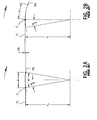
- FIG. 2A shows the chain pin center C at a first position where it has just meshed with the sprocket and where it is simultaneously aligned with both the tangent line TL and the sprocket pitch diameter PD.
- the tangent line TL is the theoretical straight-line path along which the meshing chain pin centers C approach the sprocket.
- the tangent line TL is located in a horizontal orientation, in which case the tangent line TL is tangent to the pitch diameter PD at the top-dead-center or 12 o'clock position on the pitch diameter PD, i.e., the tangent line TL is tangent to the pitch diameter PD at a location where a chain pin center is centered on the pitch diameter PD and is also centered on a radial reference line that is normal to the tangent line TL (the reference line being vertical when the tangent line is horizontal as shown herein).
- FIG. 2B illustrates the location of the same pin center C after the sprocket has rotated through the angle ⁇ /2, where it can be seen that the pin center C is transversely displaced by a distance CR as it continued its travel around the sprocket wrap, and this vertical displacement of the pin center results in a corresponding displacement of the upstream chain span and tangent line TL thereof.
- This transverse displacement of the chain pins C as they move through the chordal rise and fall serves to induce undesired vibration in the unsupported chain span.
- Horie et al. disclose an inverted tooth chain wherein the inside flanks of each link plate are defined with a compound radius profile intended to smooth the movement of the inside flanks from initial sprocket tooth meshing contact to the fully meshed (chordal) position.
- Initial meshing contact for the Horie et al link plate form occurs at a convexly arcuate portion of the inside flank at the link toe tip and proceeds smoothly and continuously to a second arcuate portion of the inside flank before transitioning to outside flank full meshing contact of a preceding link.
- Chordal motion is also reduced in the system disclosed in published U.S. patent application No. 2006/0068959 by Young et al , where the prominence of the inside flanks of the chain relative to the respective outside flanks of adjacent link plates is defined as a function of the chain pitch P, and the maximum projection of the inside flank Lamda ( ⁇ ) relative to the related outside flank is defined to fall in the range of 0.010xP ⁇ ⁇ ⁇ 0.020xP.
- Young et al disclose a link plate that also incorporates inside flank initial meshing contact to limit chordal motion, but its inside flank meshing contact begins and ends on the same convexly arcuate portion of the link plate before the meshing contact transitions to outside flank full meshing contact of a preceding link to complete the meshing cycle.
- Matsuda discloses a link plate having inside flank meshing contact with the sprocket tooth for the full meshing cycle. Although the outside flanks of the Matsuda link plate do not contact the sprocket teeth, its inside flank meshing geometry serves to restrict chordal motion during engagement.
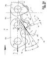
- a prior art chain link row 30c of chain 10 is at the onset of meshing with a sprocket tooth 60c of a conventional sprocket 50 in a chain drive system 15 including the chain 10, sprocket 50, and at least one other sprocket meshing with the chain 10.
- Successive pin centers C are numbered C1, C2, C3, C4, etc. to distinguish them from each other.
- the link row 30c is shown at the instant of initial meshing contact with a corresponding sprocket tooth 60c, i.e., at the instant of initial contact between the leading inside flank 36 of the chain link plate and the engaging flank 62c of the sprocket tooth 60c at an initial contact location IC on the engaging flank 62c.
- An initial contact angle Theta ( ⁇ ) is defined between a first radial reference line L1 originating at the axis of rotation of the sprocket and extending normal to the tangent line TL and a second radial reference line TC originating at the axis of rotation of the sprocket and extending through the tooth center of the subject sprocket tooth 60c.
- the preceding link row 30b exits the chain span and enters a "suspended state", i.e., the link plates 30 of row 30b are not in direct contact with the sprocket 50 and are suspended between the meshing row 30c and a preceding row 30a that is in full meshing contact with a preceding sprocket tooth 60b.
- Link row 30b will remain in this suspended state as row 30c articulates through its sliding contact with the engaging flank 62c of sprocket tooth 60c from its initial meshing contact location IC to a final inside flank meshing contact location IF, at which time row 30b completes its meshing cycle and transitions into a position where its trailing outside flanks 37 make full meshing contact at location OF with sprocket tooth 60c (contact locations IF and OF are shown in FIGS. 4 and 4A ).
- link rows 30b and 30c are in simultaneous contact with sprocket tooth 60c, and with the next increment of sprocket rotation, link row 30c will separate from its inside flank meshing contact. Upon separation, link row 30c remains in the span, and it will enter the suspended state at the instant of initial meshing impact IC for a following row 30d with sprocket tooth 60d.
- the pin center C1 can be referred to as the "controlling pin center.”
- the controlling pin center C1 is the closest preceding (downstream) pin center relative to the leading pin center C2 of the meshing link row 30c (the controlling pin center C1 is also the trailing pin center of the closest (in terms of chain travel direction) fully meshed link row 30a). As such, the following relationships are defined:
- C is a constant
- m is equal to the mass of the single meshing link row 30c
- L is the length from the controlling pin center C1 to the initial contact location IC
- ⁇ is the angular velocity of the sprocket
- ⁇ is the link plate meshing entrance angle.
- the meshing impacts along with the associated noise levels can be reduced by decreasing the velocity difference, which can be accomplished by reducing the meshing entrance angle ⁇ .
- the impact energy E equation considers only the mass of the meshing link row 30c, and it does not take into account chain tension T C and this chain tension will add to the resultant meshing impact energy E and the associated overall noise levels.
- the meshing impact angle Sigma ( ⁇ ) and its component angles are shown relative to a reference line 72 that is parallel to the tangent line TL and extending through the initial contact location IC, coincident with the force vector F H ).
- the sprocket tooth 60c, along with the next several teeth forward (downstream) of tooth 60c share in the load distribution of the chain tension T C with the largest reaction force F H occurring at location IC of tooth 60c at the onset of initial meshing contact.
- the remaining portion of the chain tension loading acting on the several teeth forward of tooth 60c does not influence the meshing noise levels and is therefore not a consideration for this present development.
- the link impact force vector F L acts at the meshing impact location IC during initial meshing contact and adds to the total meshing impact energy E and the related noise levels.
- FIG. 4 shows simultaneous meshing contact, where the leading inside flanks 36 of link row 30c are contacting the engaging flank 62c of sprocket tooth 60c at location IF, and the trailing outside flanks 37 of preceding link row 30b are contacting the engaging flank 62c are location OF.
- FIG. 4A is a greatly enlarged partial view of FIG. 4 that also shows the forces resulting from the geometry of the simultaneous meshing contact phenomenon.
- transition point This instant at which the tooth 60c transitions from "inside flank only" contact with leading inside flanks 36 of link row 30c to achieve simultaneous outside flank contact with trailing outside flanks 37 of preceding link row 30b can also be referred to as a transition point, and also defines the end of the meshing cycle for the tooth 60c, because the link row 30b is now fully meshed with both its leading and trailing pin centers C1,C2 located on the pitch diameter PD.
- a transition angle Phi ( ⁇ ) is defined between the first radial reference line L1 and the second radial reference line TC marking the tooth center of tooth 60c.
- FIGS. 4 and 4A correspond respectively to FIGS. 3 and 3A , but relate to the transition phenomenon, and show that:
- FIGS. 4 and 4A that correspond to features of FIGS. 3 and 3A are labeled with corresponding reference characters including a prime (') designation, and not all are discussed further.
- FIG. 4A the transition impact angle Sigma' ( ⁇ ') and its constituents are shown relative to a reference line 82 that is parallel to the tangent line TL and extending through the outside flank contact location OF, coincident with the force vector F' H .
- the intensity of the secondary meshing impact and the related noise level as link row 30b transitions to full chordal meshing contact at location OF with sprocket tooth 60c is a smaller value as compared to the above-described initial meshing impact at location IC and its resulting meshing noise level.
- the transition impact angle ⁇ ' will always be a smaller value than the initial meshing impact angle ⁇ .
- the outside flank contact at location OF occurs as the link row 30b transitions from the suspended state to the fully meshed state, which is believed to be less significant in terms of impact force as compared to the initial contact between the chain 10 and sprocket 50, in which a link row is collected from the chain span to impact with a sprocket tooth 60 at the onset of meshing.
- noise and vibration testing has shown the transition meshing impact of the outside flank 37 at location OF to contribute less to the overall meshing noise levels than the initial meshing impact of the inside flank 36 at location IC.
- the sprocket 50 is conventional and the teeth 60 (i.e., 60a, 60b, 60c, etc.) are each symmetrically defined about a radial tooth center TC to have an engaging flank 62 (i.e., 62a,62b,62c,etc.) that makes initial contact with the chain 10 during meshing and a matching disengaging flank 64 (i.e., 64a,64b,64c,etc.).
- the involute tooth form can be approximated by a radial tooth form, and the pressure angle PA of a radial tooth form can likewise be determined.
- an engaging flank 62 defined with a smaller pressure angle is steeper (closer to a radial line originating at the sprocket axis of rotation) as compared to an engaging flank defined with a larger pressure angle.
- a reference line tangent to the engaging flank 62 at the initial contact location IC will define an angle between itself and a radial reference line located between the engaging flank and the immediately downstream (leading) disengaging flank 64 that is smaller when the pressure angle decreased and that is larger when the pressure angle is increased.
- a chain and sprocket drive system include a sprocket comprising a plurality of teeth, wherein each tooth comprises an engaging flank and a disengaging flank.
- An inverted tooth chain is meshed with the sprocket and includes a plurality of rows of links that each articulate relative to a preceding link row about a leading pin center and that each articulate relative to a following link row about a trailing pin center, wherein said leading and trailing pin centers are spaced from each other at a chain pitch P, each of said rows comprising leading inside flanks and trailing outside flanks.
- the leading inside flanks of each row project outwardly relative to a contact or working portion of the trailing outside flanks of a preceding row and comprise an inside flank radius R.
- the chain approaches the sprocket along a tangent line and the engaging flank of each sprocket tooth makes initial meshing contact with the chain at an initial contact location on the leading inside flanks of a meshing row of the chain at an instant of initial meshing contact.
- a chain row immediately preceding the meshing row includes a leading pin center that is located on the pitch diameter so as to be a controlling pin center.
- a meshing contact angle Tau ( ⁇ ) is defined between the tangent line TL and an initial contact reference line that passes through both the controlling pin center and the initial contact location.
- a link plate entrance angle Beta ( ⁇ ) is defined between the initial contact reference line and an inside flank reference line that passes through an arc center of the inside flank radius and the initial contact location.
- an inverted tooth chain includes a plurality of rows of links that each articulate relative to a preceding row about a leading pin center and that each articulate relative to a following link row about a trailing pin center, wherein the leading and trailing pin centers are spaced from each other at a chain pitch P, each of the rows comprising leading inside flanks and trailing outside flanks, wherein the leading inside flanks of each row project outwardly relative to a working portion of the trailing outside flanks of a preceding row by a maximum projection amount Lamda ( ⁇ ) such that 0.007 ⁇ P ⁇ ⁇ ⁇ 0.017 ⁇ P .
- the leading inside flanks of each row of the chain are defined by an inside flank radius R, wherein P ⁇ R ⁇ 2 ⁇ P .
- the outside flank comprises a non-working portion comprising a chamfer located between the working portion and a toe tip for each of the links of the chain, wherein the leading inside flanks of an adjacent row of the chain project outwardly relative to the chamfer by a projection amount that is greater than the projection amount Lamda ( ⁇ ) when the inverted tooth chain is pulled straight.
- a sprocket adapted to mesh with an inverted tooth chain includes a plurality of teeth, wherein each tooth comprises an engaging flank and a disengaging flank.
- an inverted tooth chain includes a plurality of rows of links that each articulate relative to a preceding row about a leading pin center and that each articulate relative to a following link row about a trailing pin center, wherein the leading and trailing pin centers are spaced from each other at a chain pitch P, each of the rows comprising leading inside flanks and trailing outside flanks, wherein:
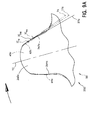
- FIG. 5 is an enlarged illustration of first and second rows of an inside flank engagement inverted tooth chain 110 formed in accordance with the present development (guide plates of the chain are not shown), showing a preferred inside flank projection Lamda (A) and outside flank profile.
- FIG. 5A is an enlarged view of detail region 5A of FIG. 5 that illustrates the inside flank projection ⁇ T relative to the outside flank chamfer 138 near the link tooth tips 139.
- FIG. 5B is an isometric view of a chain segment incorporating the link plates of FIG. 5 in accordance with the present invention to define the inverted tooth chain 110.
- the chain 110 comprises ranks or rows 130a,130b,130c,etc. of interleaved inside links or link plates 130 each with a pair of teeth 134 having outside flanks 137, and inside flanks 136, with the inside flanks 136 of the teeth 134 defining a crotch 135 therebetween.
- the teeth 134 have respective toes or tips 139.
- Each link plate 130 comprises two apertures 132 that are aligned across a link row to receive connecting pins 140 (e.g., round pins, rocker joints, etc.) to join the rows pivotally and to provide articulation of the chain about pin centers C as it drivingly engages the sprocket teeth at the inside flanks 136 ("inside flank engagement") at the onset of meshing with a sprocket such as the conventional sprocket 50.
- the pin centers C are spaced from each other at a chain pitch length or link pitch P.
- pin centers C as used herein is intended to encompass the axis of rotation of successive link rows 130a,130b,130c relative to each other, regardless of whether the pins 140 comprise round pins, rocker joints or another suitable joint.
- First and second guide plates 120 flank every other link row (the so-called “guide rows”) and serve to align the chain 110 on a sprocket but do not mesh with the sprocket teeth (the guide plates 120 are not shown in most of the figures hereof in order to reveal the underlying link plates 130).
- each link row 130a,130b,130c project outward relative to the trailing outside flanks 137 of the preceding link row 130a,130b,130c by a projection amount A when the link rows are positioned in a straight line with all pin centers C aligned along the tangent line TL as would nominally be the case in the unsupported chain span at the onset of meshing with a sprocket such as the sprocket 50.
- the tangent line TL is the theoretical straight-line path along which the meshing chain pin centers approach the sprocket.
- the tangent line TL is located in a horizontal orientation, in which case the tangent line TL is tangent to the pitch diameter PD at the top-dead-center or 12 o'clock position on the pitch diameter PD i.e., the tangent line TL is tangent to the pitch diameter PD at a location where a chain pin center is centered on the pitch diameter PD and is also centered on a radial reference line that is normal to the tangent line TL (the reference line being vertical when the tangent line is horizontal as shown herein).
- Each link plate 130 is identical to the others and is symmetrical about a vertical plane arranged perpendicular to the link plate 130 midway between the pin centers C.
- the outside flanks 137 are straight-sided (but could be curved) and for this first embodiment, the outer or outside flank angle Psi ( ⁇ ) is defined by 30° ⁇ ⁇ ⁇ 30.50, where ⁇ is defined between a first reference line W1 that is perpendicular to a reference line P R connecting the pin centers C and a second reference line W2 coincident with the outside flank 137.
- the inside flanks 136 have a convexly arcuate form and the inside flanks will preferably project outwardly relative to the outside flanks of adjacent link rows by a projection amount Lamda ( ⁇ ) to satisfy the relationship 0.007 ⁇ P ⁇ ⁇ ⁇ 0.017 ⁇ P where P is equal to the chain pitch length.
- the inside flank 136 is preferably formed to satisfy the inequality: P ⁇ R ⁇ 2 ⁇ P where R is the radius of curvature of the inside flank 136 and P is the chain pitch length.
- Each inside flank 136 is defined by a radial arc segment defined by the radius R centered at an arc center 179 ( FIG.
- the outside flanks 137 include a chamfer 138 of any desired angle adjacent the tip 139.
- the chamfer 138 assures that the initial meshing contact region 190 (see FIG. 5A ) for a leading inside flank 136 will always project outwardly from the trailing outside flank 137 of the preceding link plate 130 at the onset of meshing by an amount ⁇ T > ⁇ , particularly when the inside flank projection Lamda ( ⁇ ) is at its lower manufacturing limit.
- the chamfer 138 is flat and defines a chamfer angle 133 between itself and the plane of the remainder of the outside flank 137. A smaller value for Lamda ( ⁇ ) will beneficially provide a smaller angle Beta ( ⁇ ).
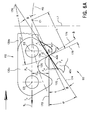
- the chain 110 will mesh with a conventional sprocket 50 as shown in FIGS. 6 and 6A and at least one other sprocket to define a chain drive system 115.
- the chain link row 130c is at the onset of meshing with a sprocket tooth 60c of sprocket 50 (reference will usually be made only to the individual chain link plates 130 visible in the foreground of each row 130a,130b,130c,etc., but those of ordinary skill in the art will recognize that each row includes multiple chain link plates 130 arranged across each row).
- Successive pin centers C are numbered C1, C2, C3, C4, etc. to distinguish them from each other.
- the row 130c is shown at the instant of initial meshing contact with a corresponding sprocket tooth 60c, i.e., at the instant of initial contact between the chain link plate inside flank 136 and the engaging flank 62c of the sprocket tooth 60c at an initial contact location IC on the engaging flank 62c.
- An initial contact angle Theta ( ⁇ ) is defined between a first radial reference line L1 originating at the axis of rotation of the sprocket and extending normal to the tangent line TL and a second radial reference line TC originating at the axis of rotation of the sprocket and extending through the tooth center of the subject sprocket tooth 60c.
- the pin center C1 is deemed the "controlling pin center” in that it is the closest (in terms of chain travel direction) preceding or downstream pin center C relative to the leading pin center C2 of the meshing link row 130c (the controlling pin center C1 is also the trailing pin center of the closest (in terms of chain travel direction) fully meshed link row 130a). As such, the following relationships are defined:
- the meshing impact angle Sigma ( ⁇ ) and its constituents are shown relative to a reference line 172 that is parallel to the tangent line TL and that extends through the initial contact location IC, coincident with the force vector F H .
- the shape of the link plates 130 of the chain 110 is designed to optimize initial meshing impact geometry at the initial contact location IC between a sprocket tooth 60c and a chain link row 130c at the leading inside flanks 136 of the link plates 130 as the sprocket tooth 60c collects the link row 130c from the chain span, to reduce the link impact force F L and the resultant impact energy E.
- the shape of the link plates 130 reduces noise and vibration levels associated with the chain-sprocket meshing phenomena.
- the improved link plate form 130 also results in optimized meshing contact geometry for the subsequent transition to full chordal meshing contact OF at the trailing outside flanks 137 of a preceding link row 130b to complete the meshing process for the same tooth.
- the inside flank 136 of link plate 130c is determined as a function of the desired initial contact location IC with a sprocket tooth 60c, and this is preferably established with a sprocket size (number of teeth) at or near the smallest tooth count for the family (range of tooth counts) of sprockets to be used with the chain 110.
- the outside flank 137 is already determined prior to this, however, since the trailing outside flank 137 of the closest fully meshed link row (in this case link row 130a) serves to position the meshing link rows 130b, 130c, and the profile for the inside flank 136 of the link plate 130 can then established at its initial meshing impact (initial contact) IC rotational position.
- tooth impact reaction force F S will vary with the magnitude of the meshing impact angle ⁇ for a constant chain tension T C , there is a benefit for the meshing impact angle ⁇ to be as small as practical when establishing the form of the inside flank 136.
- a rotational position for the controlling pin center C1 and the meshing contact angle ⁇ are selected to place the initial contact location IC in a desired region on the inside flank 136 that will serve to best satisfy the meshing geometry and link plate loading.
- the initial contact location IC on the inside flank 136 is spaced at a desired initial contact distance IC D from a pin center reference line P R that extends between the pin centers C of the link plate (pin centers C2,C3 of FIGS. 6 & 6A ).
- This desired initial contact distance IC D was determined for a sprocket 50 tooth count at or near the smallest tooth count for the family (range of tooth counts) to be used with chain 110 and IC D will vary for all other tooth counts in the range.
- the design of the inside flank 137 for the link plate 130 is therefore determined when meshing with a conventional sprocket 50 at or near the smallest used tooth count.
- the optimal initial contact distance IC D for a given link plate will be a function of the link plate design, in particular the inside flank, and IC D will of course vary as chain pitch P varies.
- a reference line 176 is tangent to both the sprocket tooth engaging flank 62 and the link plate inside flank 136 at initial contact location IC.
- the inside flank reference line 174 is thus perpendicular the reference line 176 and will therefore be normal to the involute surface of the tooth flank 62 at the initial contact location IC.
- Reference line 178 is perpendicular to initial contact reference line 170. It follows that the magnitude of the link plate entrance angle Beta ( ⁇ ) will be a resultant of the meshing contact angle ⁇ selection.
- the rotational position of the controlling pin center C1 and the meshing contact angle ⁇ selection effectively define the link plate entrance angle ⁇ , and therefore also define the meshing impact angle ⁇ .
- meshing impact reaction force F S becomes a smaller value as the meshing impact angle ⁇ is reduced.
- a value for pin center C1 rotation i.e., the rotational position of the controlling pin center C1
- FIGS. 7 and 7A correspond respectively to FIGS. 4 and 4A , in that FIGS. 7 and 7A show simultaneous meshing contact for the chain 110.
- FIG. 7 is similar to FIG. 6 but shows the sprocket 50 rotated further through the meshing cycle until the instant when the trailing outside flanks 137 of preceding link row 130b make contact with the engaging flank 62c of sprocket tooth 60c at an outside flank contact location OF while the leading inside flanks 136 of link row 130c are also contacting the engaging flank 62c at a location IF.
- transition point the instant at which the tooth 60c transitions from inside flank only contact with leading inside flanks 136 of link row 130c also to outside flank contact with trailing outside flanks 137 of preceding link row 130b at an outside flank contact point OF can be referred to as a transition point, and also defines the end of the meshing cycle for the tooth 60c, because the link row 130b is fully meshed with both its leading and trailing pin centers C1,C2 located on the pitch diameter PD.
- a transition angle Phi ( ⁇ ) is defined between the first radial reference line L1 and the second radial reference line TC passing through the tooth center of tooth 60c.
- FIG. 7A is an enlarged partial view of FIG. 7 and shows that:
- the initial contact location IC, outside flank contact location OF, and inside flank transitional contact location IF will vary depending upon the sprocket tooth count N and pressure angle, along with corresponding variation in the meshing impact angle Sigma ( ⁇ ) and transition impact angle Sigma' ( ⁇ '), given that the chain 110 is designed to mesh with a family of sprockets having a tooth count in the range of 19 to 50 for a 7.7millimeter (mm) chain link pitch P.
- the initial contact location IC will vary in a region 190
- the outside flank contact location OF will vary in a region 185
- the inside flank transitional location IF will vary in a region 192, as a function of the sprocket tooth count N and pressure angle.
- Lamda ( ⁇ ) is measured relative to the straight "contact” or “working” portion of the outside flank 137 when the chain is pulled straight. First and second rows of the chain are deemed to be pulled straight when all pin centers C thereof located on a single line.
- the working portion of an outside flank 137 is the region thereof where the outside flank contact location OF is located, for all sprocket tooth counts intended to be meshed with the chain 110.
- the chamfer 138 is referred to as a "non-contact” or “non-working” portion of the outside flank 137 because it will not contact the sprocket teeth for all sprocket tooth counts intended to be meshed with the chain 110.
- the chamfer 138 which need not be flat, is included to ensure that at least the portion of the leading inside flanks 136 of the adjacent link row required to make initial contact IC with the sprocket 50 will always project outwardly a sufficient distance relative to the adjacent row for all manufacturing tolerance conditions.
- a chain 210 as shown in FIGS. 8, 8A , 8B is defined to mesh with a new, modified sprocket 250 formed in accordance with the present development as shown in FIG. 9 .
- a chain and sprocket drive system 215 is defined by the chain 210 meshed with the sprocket 250 and at least one other sprocket defined according to the structure of the sprocket 250 (with the same or different tooth count).
- the sprocket 250 includes teeth 260 (260a,260b,260c,etc.) defined with a pressure angle that is smaller than the conventional pressure angles as shown in Table 1 above, with the result being an increased steepness of the engaging flanks 262 (262a,262b,262c,etc.) as compared to the engaging flanks 62 of sprocket 50.
- FIG. 9A shows a tooth 260c of the sprocket 250 including an engaging flank 262c and disengaging flank 264c symmetrically defined about the tooth center TC.
- the tooth 60c of the conventional sprocket 50 is shown in phantom lines. It can be seen that the tooth flanks 262c,264c defined with the smaller pressure angle are much steeper as compared to the tooth flanks 62c,64c defined with the conventional pressure angle.
- the reference lines 76 and 176 are respectively tangent to the engaging flank 62c at initial contact locations IC 10 ,IC 110 , with the initial contact location IC 10 showing the initial contact location for the chain 10 and the initial contact location IC 110 showing the initial contact location for the chain 110.
- the reference line 276 is tangent to the engaging flank 262c at initial contact location IC 210 where the leading inside flanks 236 of a meshing link row 230 of chain 210 make initial meshing contact with the engaging flank 262c.
- the outside flank angle ⁇ must also be reduced such that: ⁇ ⁇ 27 ⁇ ° in order for the chain 210 to mesh property with the sprocket 250.
- the inside flanks 236 have a convexly arcuate form and the inside flanks will preferably project outwardly relative to the outside flanks 237 of adjacent link rows by a projection amount Lamda ( ⁇ ) to satisfy the relationship 0.007 ⁇ P ⁇ ⁇ ⁇ 0.017 x P where P is equal to the chain pitch length.
- the inside flank 236 is preferably formed to satisfy the inequality: P ⁇ R ⁇ 2 ⁇ P where R is the radius of curvature of the inside flank 236 and P is the chain pitch length.
- Each inside flank 236 is defined by a radial arc segment defined by a radius R centered at an arc center 279 ( FIG. 10A ) and that extends from the crotch 235 to the tip 239.
- the sprocket 250 is identical to the sprocket 50 except as otherwise shown or described herein, and like features are labeled with reference numbers that are 200 greater than those used for the sprocket 50.
- FIGS. 10 and 10A correspond respectively to FIGS. 6 and 6A
- FIGS. 11 and 11 A correspond respectively to FIGS. 7 and 7A , except that the chain 210 and sprocket 250 are shown instead of the chain 110 and sprocket 50. As such, further discussion of FIGS.
- Table 3 that follows provides additional data for the resulting meshing impact angle Sigma ( ⁇ ) and link plate entrance angle Beta ( ⁇ ): TABLE 3 Chain Drive System Max Sigma ( ⁇ ) Max Beta ( ⁇ ) Psi ( ⁇ ) System 15, Prior Art ( FIG. 3 ) 37° 15° 30° System 115 ( FIG. 6 ) 34° 9° 30° ⁇ ⁇ ⁇ 30.5° System 215 ( FIG. 10 ) 31° 7° ⁇ 27°
- the initial contact location IC will be located on the leading inside flanks 236 at a distance IC D from a pin center reference line P R that extends between the pin centers C of the link plate 230, as measured normal to the pin center reference line.
- Beta ( ⁇ ) and Sigma ( ⁇ ) to be optimized ( ⁇ ⁇ 7° ; ⁇ ⁇ 31°) for reduced impact energy E as described above while placing the initial contact location IC at a preferred location (defined by distance IC D ) on the inside flank 236.
Landscapes
- Engineering & Computer Science (AREA)
- General Engineering & Computer Science (AREA)
- Mechanical Engineering (AREA)
- Gears, Cams (AREA)
- Devices For Conveying Motion By Means Of Endless Flexible Members (AREA)
Applications Claiming Priority (2)
| Application Number | Priority Date | Filing Date | Title |
|---|---|---|---|
| US9539308P | 2008-09-09 | 2008-09-09 | |
| EP09792370A EP2324266B1 (de) | 2008-09-09 | 2009-09-09 | Zahnketten-kettenradantriebssystem mit verringertem eingriffsaufprall |
Related Parent Applications (2)
| Application Number | Title | Priority Date | Filing Date |
|---|---|---|---|
| EP09792370A Division EP2324266B1 (de) | 2008-09-09 | 2009-09-09 | Zahnketten-kettenradantriebssystem mit verringertem eingriffsaufprall |
| EP09792370.0 Division | 2009-09-09 |
Publications (3)
| Publication Number | Publication Date |
|---|---|
| EP2538111A2 true EP2538111A2 (de) | 2012-12-26 |
| EP2538111A3 EP2538111A3 (de) | 2013-09-18 |
| EP2538111B1 EP2538111B1 (de) | 2015-03-18 |
Family
ID=41280455
Family Applications (2)
| Application Number | Title | Priority Date | Filing Date |
|---|---|---|---|
| EP09792370A Not-in-force EP2324266B1 (de) | 2008-09-09 | 2009-09-09 | Zahnketten-kettenradantriebssystem mit verringertem eingriffsaufprall |
| EP12005311.1A Not-in-force EP2538111B1 (de) | 2008-09-09 | 2009-09-09 | Umgekehrter Zahnketten-Ritzelantrieb mit reduzierter Eingriffswirkung |
Family Applications Before (1)
| Application Number | Title | Priority Date | Filing Date |
|---|---|---|---|
| EP09792370A Not-in-force EP2324266B1 (de) | 2008-09-09 | 2009-09-09 | Zahnketten-kettenradantriebssystem mit verringertem eingriffsaufprall |
Country Status (5)
| Country | Link |
|---|---|
| US (1) | US8628440B2 (de) |
| EP (2) | EP2324266B1 (de) |
| JP (1) | JP5593318B2 (de) |
| CN (1) | CN102144111B (de) |
| WO (1) | WO2010030669A1 (de) |
Families Citing this family (11)
| Publication number | Priority date | Publication date | Assignee | Title |
|---|---|---|---|---|
| US9377082B2 (en) * | 2008-09-09 | 2016-06-28 | Cloyes Gear And Products, Inc. | Inverted tooth chain and sprocket drive system with reduced meshing impact |
| JP5553783B2 (ja) * | 2011-02-01 | 2014-07-16 | 株式会社椿本チエイン | サイレントチェーン伝動装置 |
| CN102817994B (zh) * | 2012-08-19 | 2015-12-09 | 青岛征和工业股份有限公司 | 高耐磨小齿数主动链轮 |
| WO2016028421A2 (en) * | 2014-08-22 | 2016-02-25 | Schaeffler Technologies AG & Co. KG | High strength inverted tooth chain having a press-fit middle plate |
| US10359097B2 (en) * | 2016-06-07 | 2019-07-23 | Hall Labs Llc | Silent chain profile for linear movement |
| JP6773969B2 (ja) * | 2016-09-02 | 2020-10-21 | 株式会社椿本チエイン | チェーン伝動機構 |
| FR3061753B1 (fr) * | 2017-01-10 | 2019-05-31 | Serapid - France | Dispositif de chaine de poussee |
| CN107747614A (zh) * | 2017-11-22 | 2018-03-02 | 吉林大学 | 一种单一斜齿的复相链传动系统 |
| JP7011166B2 (ja) * | 2018-03-30 | 2022-01-26 | 株式会社椿本チエイン | スプロケット及び伝動機構 |
| EP3636535B1 (de) * | 2018-10-09 | 2023-08-02 | Miranda & Irmão Lda. | Antriebskettensystem |
| CN116022257A (zh) * | 2023-01-05 | 2023-04-28 | 株洲时代瑞唯减振装备有限公司 | 一种增强驱动轮驱动履带效能的方法及结构 |
Citations (3)
| Publication number | Priority date | Publication date | Assignee | Title |
|---|---|---|---|---|
| US6244983B1 (en) | 1998-08-21 | 2001-06-12 | Borg-Warner Automotive K.K. | Silent chain with inner flank engagement links and sprocket having teeth with matching surfaces |
| US6533691B2 (en) | 2000-03-15 | 2003-03-18 | Tsubakimoto Chain Co. | Low noise silent chain |
| US20060068959A1 (en) | 2004-09-24 | 2006-03-30 | Young James D | Inverted tooth chain system with inside flank engagement |
Family Cites Families (68)
| Publication number | Priority date | Publication date | Assignee | Title |
|---|---|---|---|---|
| US1598906A (en) | 1924-03-20 | 1926-09-07 | Link Belt Co | Noiseless chain |
| US1693431A (en) | 1927-01-10 | 1928-11-27 | Diamond State Fibre Company | Drive chain |
| US3377875A (en) | 1966-05-09 | 1968-04-16 | Gen Motors Corp | Chain drive power transmitting mechanism |
| US3535871A (en) | 1966-08-15 | 1970-10-27 | Borg Warner | Method for making chain links |
| US3636788A (en) | 1966-08-15 | 1972-01-25 | Borg Warner | Chain link and method for making same |
| US3495468A (en) | 1968-11-21 | 1970-02-17 | Gen Motors Corp | Chain drive |
| US4168634A (en) | 1977-05-27 | 1979-09-25 | General Motors Corporation | Chain and sprocket power transmitting mechanism |
| JPS5524203A (en) | 1978-08-04 | 1980-02-21 | Tsubakimoto Moorusu:Kk | Sprocket for driving silent chain |
| JPS6030866B2 (ja) | 1980-04-23 | 1985-07-18 | ボルグ・ワ−ナ−・オ−トモ−テイブ株式会社 | サイレントチエ−ン用スプロケット |
| US4509937A (en) | 1981-12-18 | 1985-04-09 | Borg-Warner Corporation | Power transmission chain |
| US4509323A (en) | 1981-12-18 | 1985-04-09 | Borg-Warner Corporation | Power transmission chain |
| US4832668A (en) | 1984-10-17 | 1989-05-23 | Borg-Warner Corporation | Power transmission chain |
| US4764158A (en) | 1985-11-27 | 1988-08-16 | Honda Giken Kogyo Kabushiki Kaisha | Power transmission chain |
| US4758209A (en) | 1987-04-01 | 1988-07-19 | Borg-Warner Automotive, Inc. | Silent timing chain and sprocket system |
| US4759740A (en) | 1987-04-01 | 1988-07-26 | Borg-Warner Automotive, Inc. | Dual engaging silent chain drive |
| US4758210A (en) | 1987-04-01 | 1988-07-19 | Borg-Warner Automotive, Inc. | Silent chain and sprocket system |
| JPH01119964A (ja) | 1987-11-02 | 1989-05-12 | Hitachi Ltd | 記憶装置 |
| JPH06682Y2 (ja) | 1988-06-15 | 1994-01-05 | 大同工業株式会社 | チェーン |
| US4906224A (en) | 1989-02-22 | 1990-03-06 | Magna International, Inc. | Inverted tooth chain |
| US4915675B1 (en) | 1989-02-28 | 1998-12-29 | Borg Warner Automotive | Pitch equalized chain with frequency modulated engagement |
| US5154674A (en) | 1990-04-25 | 1992-10-13 | Borg-Warner Automotive Transmission & Engine Components Corporation | Power transmission chain constructed with asymmetrical links |
| JPH0444543U (de) | 1990-08-20 | 1992-04-15 | ||
| JPH081312Y2 (ja) | 1992-03-30 | 1996-01-17 | 株式会社椿本チエイン | 低騒音サイレントチェ−ン |
| US5453059A (en) | 1992-05-19 | 1995-09-26 | Borg-Warner Automotive, Inc. | Variable pitch silent chain |
| JP2560185B2 (ja) | 1992-11-20 | 1996-12-04 | ボーグ・ワーナー・オートモーティブ株式会社 | 低騒音チエーン伝動装置 |
| US5464374A (en) | 1994-08-03 | 1995-11-07 | Borg-Warner Automotive, Inc. | Chain having improved load distribution |
| JPH0874940A (ja) | 1994-09-02 | 1996-03-19 | Borg Warner Automot Kk | 動力伝達用チェーン |
| JPH09250599A (ja) | 1996-03-18 | 1997-09-22 | Honda Motor Co Ltd | サイレントチェーン |
| JP3075986B2 (ja) | 1996-06-13 | 2000-08-14 | 株式会社椿本チエイン | サイレントチェーンのプレート |
| US5758484A (en) | 1996-09-30 | 1998-06-02 | Borg-Warner Automotive, Inc. | Silent chain with raised link backs |
| JPH1119964A (ja) | 1997-07-01 | 1999-01-26 | Nishikawa Kasei Co Ltd | 表皮一体樹脂成形品及びその成形方法 |
| JP3261089B2 (ja) | 1997-12-29 | 2002-02-25 | ボーグ・ワーナー・オートモーティブ株式会社 | サイレントチェーン用リンクプレート |
| JP3420696B2 (ja) | 1997-12-29 | 2003-06-30 | ボルグワーナー・モールステック・ジャパン株式会社 | サイレントチェーン伝動装置 |
| JP3470036B2 (ja) | 1998-01-29 | 2003-11-25 | ボルグワーナー・モールステック・ジャパン株式会社 | サイレントチェーン伝動装置 |
| US6186920B1 (en) | 1998-02-10 | 2001-02-13 | Cloyes Gear And Products, Inc. | Short pitch tooth chain |
| JP3096274B2 (ja) | 1998-06-30 | 2000-10-10 | 株式会社椿本チエイン | サイレントチェーン |
| JP3096276B2 (ja) | 1998-08-31 | 2000-10-10 | 株式会社椿本チエイン | サイレントチェーン伝動装置 |
| JP3076022B1 (ja) | 1999-02-16 | 2000-08-14 | 株式会社椿本チエイン | サイレントチェーン伝動装置 |
| JP3081198B1 (ja) | 1999-02-18 | 2000-08-28 | 株式会社椿本チエイン | サイレントチェーン |
| JP3069345B1 (ja) | 1999-06-02 | 2000-07-24 | 株式会社椿本チエイン | サイレントチェ―ン用プレ―トおよびその製造方法 |
| JP3054144B1 (ja) | 1999-06-03 | 2000-06-19 | 株式会社椿本チエイン | サイレントチェーン |
| JP3091454B1 (ja) | 1999-06-23 | 2000-09-25 | 株式会社椿本チエイン | サイレントチェーン |
| JP2001021010A (ja) | 1999-07-06 | 2001-01-26 | Tsubakimoto Chain Co | サイレントチェーンとスプロケットとの組合せによる動力伝動機構 |
| JP3096293B1 (ja) | 1999-07-22 | 2000-10-10 | 株式会社椿本チエイン | サイレントチェーン伝動装置 |
| JP3091458B1 (ja) | 1999-10-29 | 2000-09-25 | 株式会社椿本チエイン | サイレントチェ−ン |
| JP3187802B1 (ja) * | 2000-01-12 | 2001-07-16 | 株式会社椿本チエイン | サイレントチェーン駆動機構 |
| JP3108417B1 (ja) | 2000-04-19 | 2000-11-13 | 株式会社椿本チエイン | サイレントチェーン伝動装置 |
| JP3402591B2 (ja) | 2000-09-26 | 2003-05-06 | 株式会社椿本チエイン | サイレントチェーン伝動機構 |
| JP2002130385A (ja) | 2000-10-26 | 2002-05-09 | Tsubakimoto Chain Co | 耐摩耗伸びサイレントチェーン |
| EP1235003A1 (de) | 2001-02-23 | 2002-08-28 | Morse Tec Europe S.p.A. | Rollenkettenrad mit unterschiedlichen Zahnprofilen auf dem gleichem Kettenrad |
| JP2002250406A (ja) | 2001-02-23 | 2002-09-06 | Tsubakimoto Chain Co | ランダム配置型サイレントチェーン |
| JP4149688B2 (ja) | 2001-07-24 | 2008-09-10 | 株式会社椿本チエイン | サイレントチェーン伝動機構 |
| JP4683451B2 (ja) | 2001-08-03 | 2011-05-18 | 株式会社椿本チエイン | サイレントチェーン伝動機構 |
| JP2003065398A (ja) * | 2001-08-23 | 2003-03-05 | Borg Warner Morse Tec Japan Kk | サイレントチェーン用リンクプレート、該リンクプレートを含むサイレントチェーンおよび該サイレントチェーンを含むサイレントチェーン伝動装置 |
| JP3589650B2 (ja) | 2001-12-20 | 2004-11-17 | 株式会社椿本チエイン | サイレントチェーン伝動機構 |
| JP3585463B2 (ja) | 2001-12-28 | 2004-11-04 | 株式会社椿本チエイン | サイレントチェーン伝動装置 |
| US20040166978A1 (en) | 2002-10-24 | 2004-08-26 | Borgwarner Morse Tec Japan K.K. | Silent chain and method of producing the same |
| JP2004169747A (ja) | 2002-11-18 | 2004-06-17 | Borg Warner Morse Tec Japan Kk | サイレントチェーン |
| JP2004183851A (ja) * | 2002-12-06 | 2004-07-02 | Borg Warner Morse Tec Japan Kk | サイレントチェーン |
| CN2651514Y (zh) | 2003-10-15 | 2004-10-27 | 许长荣 | 一种齿形链 |
| JP2005248969A (ja) * | 2003-11-28 | 2005-09-15 | Shigeyoshi Osada | サイレントチェーン伝動装置 |
| CN101010525B (zh) | 2004-08-26 | 2012-07-04 | 克劳伊斯传动装置产品有限公司 | 具有调节频率啮合的逆齿链链轮 |
| CN2771564Y (zh) | 2004-11-16 | 2006-04-12 | 单金龙 | 一种链条 |
| US20070142150A1 (en) * | 2005-10-26 | 2007-06-21 | Luk Lamellen Und Kupplungsbau Beteiligungs Kg | Link plate for a plate-link chain |
| EP2357379B1 (de) * | 2005-12-13 | 2018-01-17 | BorgWarner, Inc. | Leise kette von hoher festigkeit und steifheit mit verbesserter geräuschemission |
| JP4267035B2 (ja) | 2007-01-09 | 2009-05-27 | 株式会社椿本チエイン | サイレントチェーンのリンクプレート |
| WO2008143811A2 (en) | 2007-05-11 | 2008-11-27 | Cloyes Gear And Products, Inc. | Inverted tooth chain sprocket with frequency modulated meshing |
| US20100227720A1 (en) | 2008-03-06 | 2010-09-09 | Borgwarner Inc. | Sprocket randomization for enhanced nvh control |
-
2009
- 2009-09-09 JP JP2011526939A patent/JP5593318B2/ja not_active Expired - Fee Related
- 2009-09-09 WO PCT/US2009/056364 patent/WO2010030669A1/en active Application Filing
- 2009-09-09 EP EP09792370A patent/EP2324266B1/de not_active Not-in-force
- 2009-09-09 CN CN200980134898.9A patent/CN102144111B/zh not_active Expired - Fee Related
- 2009-09-09 EP EP12005311.1A patent/EP2538111B1/de not_active Not-in-force
- 2009-09-09 US US12/556,332 patent/US8628440B2/en not_active Expired - Fee Related
Patent Citations (3)
| Publication number | Priority date | Publication date | Assignee | Title |
|---|---|---|---|---|
| US6244983B1 (en) | 1998-08-21 | 2001-06-12 | Borg-Warner Automotive K.K. | Silent chain with inner flank engagement links and sprocket having teeth with matching surfaces |
| US6533691B2 (en) | 2000-03-15 | 2003-03-18 | Tsubakimoto Chain Co. | Low noise silent chain |
| US20060068959A1 (en) | 2004-09-24 | 2006-03-30 | Young James D | Inverted tooth chain system with inside flank engagement |
Also Published As
| Publication number | Publication date |
|---|---|
| US20100069187A1 (en) | 2010-03-18 |
| US8628440B2 (en) | 2014-01-14 |
| EP2324266B1 (de) | 2012-07-25 |
| JP2012502239A (ja) | 2012-01-26 |
| EP2538111A3 (de) | 2013-09-18 |
| CN102144111A (zh) | 2011-08-03 |
| EP2324266A1 (de) | 2011-05-25 |
| JP5593318B2 (ja) | 2014-09-24 |
| CN102144111B (zh) | 2014-07-02 |
| EP2538111B1 (de) | 2015-03-18 |
| WO2010030669A1 (en) | 2010-03-18 |
Similar Documents
| Publication | Publication Date | Title |
|---|---|---|
| EP2538111B1 (de) | Umgekehrter Zahnketten-Ritzelantrieb mit reduzierter Eingriffswirkung | |
| US8672786B2 (en) | Inverted tooth chain and sprocket drive system with reduced meshing impact | |
| EP2475912B1 (de) | Umgekehrte zahnkette und ritzelantrieb mit reduzierter eingriffswirkung | |
| US7789783B2 (en) | Inverted tooth chain system with inside flank engagement | |
| US9377082B2 (en) | Inverted tooth chain and sprocket drive system with reduced meshing impact | |
| US6186921B1 (en) | Rocker joint silent chain having a joint pin thicker than a corresponding rocker pin | |
| EP2556272B1 (de) | Umgekehrte zahnkettenrolle mit frequenzmoduliertem zahneingriff | |
| US7850565B2 (en) | Plate-link chain | |
| EP0933557B1 (de) | Zahnkette mit konvexer Aussenfläche um mit einem Zahnrad regelmässig einzugreifen | |
| US5562559A (en) | Rocker joint chain with crescent shaped aperture | |
| EP1610030B1 (de) | Treibkette | |
| US6159122A (en) | Silent chain | |
| US20090000852A1 (en) | Silent Chain with Asymmetric Involute Profile | |
| EP1960696B1 (de) | Kraftübertragungsvorrichtung mit geräuschloser kette | |
| EP2133591A1 (de) | Zahnkette | |
| GB2436359A (en) | Chain drive assembly | |
| US12038068B2 (en) | Silent chain drive device |
Legal Events
| Date | Code | Title | Description |
|---|---|---|---|
| PUAI | Public reference made under article 153(3) epc to a published international application that has entered the european phase |
Free format text: ORIGINAL CODE: 0009012 |
|
| AC | Divisional application: reference to earlier application |
Ref document number: 2324266 Country of ref document: EP Kind code of ref document: P |
|
| AK | Designated contracting states |
Kind code of ref document: A2 Designated state(s): AT BE BG CH CY CZ DE DK EE ES FI FR GB GR HR HU IE IS IT LI LT LU LV MC MK MT NL NO PL PT RO SE SI SK SM TR |
|
| PUAL | Search report despatched |
Free format text: ORIGINAL CODE: 0009013 |
|
| AK | Designated contracting states |
Kind code of ref document: A3 Designated state(s): AT BE BG CH CY CZ DE DK EE ES FI FR GB GR HR HU IE IS IT LI LT LU LV MC MK MT NL NO PL PT RO SE SI SK SM TR |
|
| RIC1 | Information provided on ipc code assigned before grant |
Ipc: F16H 7/06 20060101ALI20130815BHEP Ipc: F16G 3/04 20060101ALI20130815BHEP Ipc: F16G 13/04 20060101AFI20130815BHEP |
|
| 17P | Request for examination filed |
Effective date: 20140317 |
|
| RBV | Designated contracting states (corrected) |
Designated state(s): AT BE BG CH CY CZ DE DK EE ES FI FR GB GR HR HU IE IS IT LI LT LU LV MC MK MT NL NO PL PT RO SE SI SK SM TR |
|
| GRAP | Despatch of communication of intention to grant a patent |
Free format text: ORIGINAL CODE: EPIDOSNIGR1 |
|
| INTG | Intention to grant announced |
Effective date: 20141030 |
|
| GRAS | Grant fee paid |
Free format text: ORIGINAL CODE: EPIDOSNIGR3 |
|
| GRAA | (expected) grant |
Free format text: ORIGINAL CODE: 0009210 |
|
| AC | Divisional application: reference to earlier application |
Ref document number: 2324266 Country of ref document: EP Kind code of ref document: P |
|
| AK | Designated contracting states |
Kind code of ref document: B1 Designated state(s): AT BE BG CH CY CZ DE DK EE ES FI FR GB GR HR HU IE IS IT LI LT LU LV MC MK MT NL NO PL PT RO SE SI SK SM TR |
|
| REG | Reference to a national code |
Ref country code: GB Ref legal event code: FG4D |
|
| REG | Reference to a national code |
Ref country code: CH Ref legal event code: EP |
|
| REG | Reference to a national code |
Ref country code: IE Ref legal event code: FG4D |
|
| REG | Reference to a national code |
Ref country code: AT Ref legal event code: REF Ref document number: 716794 Country of ref document: AT Kind code of ref document: T Effective date: 20150415 |
|
| REG | Reference to a national code |
Ref country code: DE Ref legal event code: R096 Ref document number: 602009030117 Country of ref document: DE Effective date: 20150430 |
|
| REG | Reference to a national code |
Ref country code: NL Ref legal event code: VDEP Effective date: 20150318 |
|
| REG | Reference to a national code |
Ref country code: NL Ref legal event code: VDEP Effective date: 20150318 |
|
| PG25 | Lapsed in a contracting state [announced via postgrant information from national office to epo] |
Ref country code: SE Free format text: LAPSE BECAUSE OF FAILURE TO SUBMIT A TRANSLATION OF THE DESCRIPTION OR TO PAY THE FEE WITHIN THE PRESCRIBED TIME-LIMIT Effective date: 20150318 Ref country code: NO Free format text: LAPSE BECAUSE OF FAILURE TO SUBMIT A TRANSLATION OF THE DESCRIPTION OR TO PAY THE FEE WITHIN THE PRESCRIBED TIME-LIMIT Effective date: 20150618 Ref country code: HR Free format text: LAPSE BECAUSE OF FAILURE TO SUBMIT A TRANSLATION OF THE DESCRIPTION OR TO PAY THE FEE WITHIN THE PRESCRIBED TIME-LIMIT Effective date: 20150318 Ref country code: LT Free format text: LAPSE BECAUSE OF FAILURE TO SUBMIT A TRANSLATION OF THE DESCRIPTION OR TO PAY THE FEE WITHIN THE PRESCRIBED TIME-LIMIT Effective date: 20150318 Ref country code: FI Free format text: LAPSE BECAUSE OF FAILURE TO SUBMIT A TRANSLATION OF THE DESCRIPTION OR TO PAY THE FEE WITHIN THE PRESCRIBED TIME-LIMIT Effective date: 20150318 |
|
| REG | Reference to a national code |
Ref country code: AT Ref legal event code: MK05 Ref document number: 716794 Country of ref document: AT Kind code of ref document: T Effective date: 20150318 |
|
| REG | Reference to a national code |
Ref country code: LT Ref legal event code: MG4D Ref country code: FR Ref legal event code: PLFP Year of fee payment: 7 |
|
| PG25 | Lapsed in a contracting state [announced via postgrant information from national office to epo] |
Ref country code: GR Free format text: LAPSE BECAUSE OF FAILURE TO SUBMIT A TRANSLATION OF THE DESCRIPTION OR TO PAY THE FEE WITHIN THE PRESCRIBED TIME-LIMIT Effective date: 20150619 Ref country code: LV Free format text: LAPSE BECAUSE OF FAILURE TO SUBMIT A TRANSLATION OF THE DESCRIPTION OR TO PAY THE FEE WITHIN THE PRESCRIBED TIME-LIMIT Effective date: 20150318 |
|
| PG25 | Lapsed in a contracting state [announced via postgrant information from national office to epo] |
Ref country code: NL Free format text: LAPSE BECAUSE OF FAILURE TO SUBMIT A TRANSLATION OF THE DESCRIPTION OR TO PAY THE FEE WITHIN THE PRESCRIBED TIME-LIMIT Effective date: 20150318 |
|
| PG25 | Lapsed in a contracting state [announced via postgrant information from national office to epo] |
Ref country code: RO Free format text: LAPSE BECAUSE OF FAILURE TO SUBMIT A TRANSLATION OF THE DESCRIPTION OR TO PAY THE FEE WITHIN THE PRESCRIBED TIME-LIMIT Effective date: 20150318 Ref country code: PT Free format text: LAPSE BECAUSE OF FAILURE TO SUBMIT A TRANSLATION OF THE DESCRIPTION OR TO PAY THE FEE WITHIN THE PRESCRIBED TIME-LIMIT Effective date: 20150720 Ref country code: ES Free format text: LAPSE BECAUSE OF FAILURE TO SUBMIT A TRANSLATION OF THE DESCRIPTION OR TO PAY THE FEE WITHIN THE PRESCRIBED TIME-LIMIT Effective date: 20150318 Ref country code: CZ Free format text: LAPSE BECAUSE OF FAILURE TO SUBMIT A TRANSLATION OF THE DESCRIPTION OR TO PAY THE FEE WITHIN THE PRESCRIBED TIME-LIMIT Effective date: 20150318 Ref country code: EE Free format text: LAPSE BECAUSE OF FAILURE TO SUBMIT A TRANSLATION OF THE DESCRIPTION OR TO PAY THE FEE WITHIN THE PRESCRIBED TIME-LIMIT Effective date: 20150318 Ref country code: SK Free format text: LAPSE BECAUSE OF FAILURE TO SUBMIT A TRANSLATION OF THE DESCRIPTION OR TO PAY THE FEE WITHIN THE PRESCRIBED TIME-LIMIT Effective date: 20150318 |
|
| PG25 | Lapsed in a contracting state [announced via postgrant information from national office to epo] |
Ref country code: AT Free format text: LAPSE BECAUSE OF FAILURE TO SUBMIT A TRANSLATION OF THE DESCRIPTION OR TO PAY THE FEE WITHIN THE PRESCRIBED TIME-LIMIT Effective date: 20150318 Ref country code: PL Free format text: LAPSE BECAUSE OF FAILURE TO SUBMIT A TRANSLATION OF THE DESCRIPTION OR TO PAY THE FEE WITHIN THE PRESCRIBED TIME-LIMIT Effective date: 20150318 Ref country code: IS Free format text: LAPSE BECAUSE OF FAILURE TO SUBMIT A TRANSLATION OF THE DESCRIPTION OR TO PAY THE FEE WITHIN THE PRESCRIBED TIME-LIMIT Effective date: 20150718 |
|
| PGFP | Annual fee paid to national office [announced via postgrant information from national office to epo] |
Ref country code: FR Payment date: 20150825 Year of fee payment: 7 |
|
| REG | Reference to a national code |
Ref country code: DE Ref legal event code: R097 Ref document number: 602009030117 Country of ref document: DE |
|
| PGFP | Annual fee paid to national office [announced via postgrant information from national office to epo] |
Ref country code: IT Payment date: 20150914 Year of fee payment: 7 |
|
| PLBE | No opposition filed within time limit |
Free format text: ORIGINAL CODE: 0009261 |
|
| STAA | Information on the status of an ep patent application or granted ep patent |
Free format text: STATUS: NO OPPOSITION FILED WITHIN TIME LIMIT |
|
| PG25 | Lapsed in a contracting state [announced via postgrant information from national office to epo] |
Ref country code: DK Free format text: LAPSE BECAUSE OF FAILURE TO SUBMIT A TRANSLATION OF THE DESCRIPTION OR TO PAY THE FEE WITHIN THE PRESCRIBED TIME-LIMIT Effective date: 20150318 |
|
| 26N | No opposition filed |
Effective date: 20151221 |
|
| PG25 | Lapsed in a contracting state [announced via postgrant information from national office to epo] |
Ref country code: SI Free format text: LAPSE BECAUSE OF FAILURE TO SUBMIT A TRANSLATION OF THE DESCRIPTION OR TO PAY THE FEE WITHIN THE PRESCRIBED TIME-LIMIT Effective date: 20150318 |
|
| PG25 | Lapsed in a contracting state [announced via postgrant information from national office to epo] |
Ref country code: LU Free format text: LAPSE BECAUSE OF FAILURE TO SUBMIT A TRANSLATION OF THE DESCRIPTION OR TO PAY THE FEE WITHIN THE PRESCRIBED TIME-LIMIT Effective date: 20150909 Ref country code: MC Free format text: LAPSE BECAUSE OF FAILURE TO SUBMIT A TRANSLATION OF THE DESCRIPTION OR TO PAY THE FEE WITHIN THE PRESCRIBED TIME-LIMIT Effective date: 20150318 |
|
| REG | Reference to a national code |
Ref country code: CH Ref legal event code: PL |
|
| REG | Reference to a national code |
Ref country code: IE Ref legal event code: MM4A |
|
| PG25 | Lapsed in a contracting state [announced via postgrant information from national office to epo] |
Ref country code: IE Free format text: LAPSE BECAUSE OF NON-PAYMENT OF DUE FEES Effective date: 20150909 Ref country code: CH Free format text: LAPSE BECAUSE OF NON-PAYMENT OF DUE FEES Effective date: 20150930 Ref country code: LI Free format text: LAPSE BECAUSE OF NON-PAYMENT OF DUE FEES Effective date: 20150930 |
|
| PG25 | Lapsed in a contracting state [announced via postgrant information from national office to epo] |
Ref country code: BE Free format text: LAPSE BECAUSE OF FAILURE TO SUBMIT A TRANSLATION OF THE DESCRIPTION OR TO PAY THE FEE WITHIN THE PRESCRIBED TIME-LIMIT Effective date: 20150318 |
|
| PG25 | Lapsed in a contracting state [announced via postgrant information from national office to epo] |
Ref country code: MT Free format text: LAPSE BECAUSE OF FAILURE TO SUBMIT A TRANSLATION OF THE DESCRIPTION OR TO PAY THE FEE WITHIN THE PRESCRIBED TIME-LIMIT Effective date: 20150318 |
|
| PG25 | Lapsed in a contracting state [announced via postgrant information from national office to epo] |
Ref country code: BG Free format text: LAPSE BECAUSE OF FAILURE TO SUBMIT A TRANSLATION OF THE DESCRIPTION OR TO PAY THE FEE WITHIN THE PRESCRIBED TIME-LIMIT Effective date: 20150318 Ref country code: HU Free format text: LAPSE BECAUSE OF FAILURE TO SUBMIT A TRANSLATION OF THE DESCRIPTION OR TO PAY THE FEE WITHIN THE PRESCRIBED TIME-LIMIT; INVALID AB INITIO Effective date: 20090909 Ref country code: SM Free format text: LAPSE BECAUSE OF FAILURE TO SUBMIT A TRANSLATION OF THE DESCRIPTION OR TO PAY THE FEE WITHIN THE PRESCRIBED TIME-LIMIT Effective date: 20150318 |
|
| PG25 | Lapsed in a contracting state [announced via postgrant information from national office to epo] |
Ref country code: CY Free format text: LAPSE BECAUSE OF FAILURE TO SUBMIT A TRANSLATION OF THE DESCRIPTION OR TO PAY THE FEE WITHIN THE PRESCRIBED TIME-LIMIT Effective date: 20150318 |
|
| REG | Reference to a national code |
Ref country code: FR Ref legal event code: ST Effective date: 20170531 |
|
| PG25 | Lapsed in a contracting state [announced via postgrant information from national office to epo] |
Ref country code: FR Free format text: LAPSE BECAUSE OF NON-PAYMENT OF DUE FEES Effective date: 20160930 |
|
| PG25 | Lapsed in a contracting state [announced via postgrant information from national office to epo] |
Ref country code: IT Free format text: LAPSE BECAUSE OF NON-PAYMENT OF DUE FEES Effective date: 20160909 Ref country code: TR Free format text: LAPSE BECAUSE OF FAILURE TO SUBMIT A TRANSLATION OF THE DESCRIPTION OR TO PAY THE FEE WITHIN THE PRESCRIBED TIME-LIMIT Effective date: 20150318 |
|
| PGFP | Annual fee paid to national office [announced via postgrant information from national office to epo] |
Ref country code: GB Payment date: 20170829 Year of fee payment: 9 |
|
| PGFP | Annual fee paid to national office [announced via postgrant information from national office to epo] |
Ref country code: DE Payment date: 20170928 Year of fee payment: 9 |
|
| PG25 | Lapsed in a contracting state [announced via postgrant information from national office to epo] |
Ref country code: MK Free format text: LAPSE BECAUSE OF FAILURE TO SUBMIT A TRANSLATION OF THE DESCRIPTION OR TO PAY THE FEE WITHIN THE PRESCRIBED TIME-LIMIT Effective date: 20150318 |
|
| REG | Reference to a national code |
Ref country code: DE Ref legal event code: R119 Ref document number: 602009030117 Country of ref document: DE |
|
| GBPC | Gb: european patent ceased through non-payment of renewal fee |
Effective date: 20180909 |
|
| PG25 | Lapsed in a contracting state [announced via postgrant information from national office to epo] |
Ref country code: DE Free format text: LAPSE BECAUSE OF NON-PAYMENT OF DUE FEES Effective date: 20190402 |
|
| PG25 | Lapsed in a contracting state [announced via postgrant information from national office to epo] |
Ref country code: GB Free format text: LAPSE BECAUSE OF NON-PAYMENT OF DUE FEES Effective date: 20180909 |