EP2521659B1 - A tilting vehicle and a method of tilting a vehicle with rear wheel supports having hydraulic cylinders communicating through a pump - Google Patents
A tilting vehicle and a method of tilting a vehicle with rear wheel supports having hydraulic cylinders communicating through a pump Download PDFInfo
- Publication number
- EP2521659B1 EP2521659B1 EP11700575.1A EP11700575A EP2521659B1 EP 2521659 B1 EP2521659 B1 EP 2521659B1 EP 11700575 A EP11700575 A EP 11700575A EP 2521659 B1 EP2521659 B1 EP 2521659B1
- Authority
- EP
- European Patent Office
- Prior art keywords
- chassis
- vehicle
- rear wheel
- hydraulic cylinder
- wheel support
- Prior art date
- Legal status (The legal status is an assumption and is not a legal conclusion. Google has not performed a legal analysis and makes no representation as to the accuracy of the status listed.)
- Active
Links
- 238000000034 method Methods 0.000 title claims description 8
- 239000012530 fluid Substances 0.000 claims description 61
- 230000035939 shock Effects 0.000 claims description 37
- 239000006096 absorbing agent Substances 0.000 claims description 35
- 238000004891 communication Methods 0.000 claims description 19
- 230000000712 assembly Effects 0.000 claims description 18
- 238000000429 assembly Methods 0.000 claims description 18
- 230000005484 gravity Effects 0.000 claims description 14
- 230000002457 bidirectional effect Effects 0.000 claims description 3
- 235000004443 Ricinus communis Nutrition 0.000 description 18
- 230000007246 mechanism Effects 0.000 description 13
- 239000000725 suspension Substances 0.000 description 9
- 230000037396 body weight Effects 0.000 description 7
- 238000002485 combustion reaction Methods 0.000 description 7
- 238000013016 damping Methods 0.000 description 7
- 238000010276 construction Methods 0.000 description 5
- 239000000446 fuel Substances 0.000 description 5
- 239000002828 fuel tank Substances 0.000 description 5
- 230000006835 compression Effects 0.000 description 4
- 238000007906 compression Methods 0.000 description 4
- 238000004806 packaging method and process Methods 0.000 description 4
- 230000001133 acceleration Effects 0.000 description 3
- 230000000295 complement effect Effects 0.000 description 2
- 238000010586 diagram Methods 0.000 description 2
- 238000006073 displacement reaction Methods 0.000 description 2
- 230000000694 effects Effects 0.000 description 2
- 239000000463 material Substances 0.000 description 2
- 238000005086 pumping Methods 0.000 description 2
- OKTJSMMVPCPJKN-UHFFFAOYSA-N Carbon Chemical compound [C] OKTJSMMVPCPJKN-UHFFFAOYSA-N 0.000 description 1
- 239000004606 Fillers/Extenders Substances 0.000 description 1
- HBBGRARXTFLTSG-UHFFFAOYSA-N Lithium ion Chemical compound [Li+] HBBGRARXTFLTSG-UHFFFAOYSA-N 0.000 description 1
- 238000010521 absorption reaction Methods 0.000 description 1
- XAGFODPZIPBFFR-UHFFFAOYSA-N aluminium Chemical compound [Al] XAGFODPZIPBFFR-UHFFFAOYSA-N 0.000 description 1
- 229910052782 aluminium Inorganic materials 0.000 description 1
- 239000004411 aluminium Substances 0.000 description 1
- 230000009286 beneficial effect Effects 0.000 description 1
- 229910052799 carbon Inorganic materials 0.000 description 1
- 230000007423 decrease Effects 0.000 description 1
- 239000002305 electric material Substances 0.000 description 1
- 239000000835 fiber Substances 0.000 description 1
- 229910001416 lithium ion Inorganic materials 0.000 description 1
Images


Classifications
-
- B—PERFORMING OPERATIONS; TRANSPORTING
- B60—VEHICLES IN GENERAL
- B60G—VEHICLE SUSPENSION ARRANGEMENTS
- B60G21/00—Interconnection systems for two or more resiliently-suspended wheels, e.g. for stabilising a vehicle body with respect to acceleration, deceleration or centrifugal forces
- B60G21/02—Interconnection systems for two or more resiliently-suspended wheels, e.g. for stabilising a vehicle body with respect to acceleration, deceleration or centrifugal forces permanently interconnected
- B60G21/06—Interconnection systems for two or more resiliently-suspended wheels, e.g. for stabilising a vehicle body with respect to acceleration, deceleration or centrifugal forces permanently interconnected fluid
- B60G21/073—Interconnection systems for two or more resiliently-suspended wheels, e.g. for stabilising a vehicle body with respect to acceleration, deceleration or centrifugal forces permanently interconnected fluid between wheels on the same axle but on different sides of the vehicle, i.e. the left and right wheel suspensions being interconnected
-
- B—PERFORMING OPERATIONS; TRANSPORTING
- B60—VEHICLES IN GENERAL
- B60G—VEHICLE SUSPENSION ARRANGEMENTS
- B60G17/00—Resilient suspensions having means for adjusting the spring or vibration-damper characteristics, for regulating the distance between a supporting surface and a sprung part of vehicle or for locking suspension during use to meet varying vehicular or surface conditions, e.g. due to speed or load
- B60G17/005—Suspension locking arrangements
-
- B—PERFORMING OPERATIONS; TRANSPORTING
- B60—VEHICLES IN GENERAL
- B60G—VEHICLE SUSPENSION ARRANGEMENTS
- B60G17/00—Resilient suspensions having means for adjusting the spring or vibration-damper characteristics, for regulating the distance between a supporting surface and a sprung part of vehicle or for locking suspension during use to meet varying vehicular or surface conditions, e.g. due to speed or load
- B60G17/015—Resilient suspensions having means for adjusting the spring or vibration-damper characteristics, for regulating the distance between a supporting surface and a sprung part of vehicle or for locking suspension during use to meet varying vehicular or surface conditions, e.g. due to speed or load the regulating means comprising electric or electronic elements
- B60G17/0152—Resilient suspensions having means for adjusting the spring or vibration-damper characteristics, for regulating the distance between a supporting surface and a sprung part of vehicle or for locking suspension during use to meet varying vehicular or surface conditions, e.g. due to speed or load the regulating means comprising electric or electronic elements characterised by the action on a particular type of suspension unit
-
- B—PERFORMING OPERATIONS; TRANSPORTING
- B60—VEHICLES IN GENERAL
- B60G—VEHICLE SUSPENSION ARRANGEMENTS
- B60G17/00—Resilient suspensions having means for adjusting the spring or vibration-damper characteristics, for regulating the distance between a supporting surface and a sprung part of vehicle or for locking suspension during use to meet varying vehicular or surface conditions, e.g. due to speed or load
- B60G17/015—Resilient suspensions having means for adjusting the spring or vibration-damper characteristics, for regulating the distance between a supporting surface and a sprung part of vehicle or for locking suspension during use to meet varying vehicular or surface conditions, e.g. due to speed or load the regulating means comprising electric or electronic elements
- B60G17/016—Resilient suspensions having means for adjusting the spring or vibration-damper characteristics, for regulating the distance between a supporting surface and a sprung part of vehicle or for locking suspension during use to meet varying vehicular or surface conditions, e.g. due to speed or load the regulating means comprising electric or electronic elements characterised by their responsiveness, when the vehicle is travelling, to specific motion, a specific condition, or driver input
- B60G17/0162—Resilient suspensions having means for adjusting the spring or vibration-damper characteristics, for regulating the distance between a supporting surface and a sprung part of vehicle or for locking suspension during use to meet varying vehicular or surface conditions, e.g. due to speed or load the regulating means comprising electric or electronic elements characterised by their responsiveness, when the vehicle is travelling, to specific motion, a specific condition, or driver input mainly during a motion involving steering operation, e.g. cornering, overtaking
-
- B—PERFORMING OPERATIONS; TRANSPORTING
- B60—VEHICLES IN GENERAL
- B60G—VEHICLE SUSPENSION ARRANGEMENTS
- B60G21/00—Interconnection systems for two or more resiliently-suspended wheels, e.g. for stabilising a vehicle body with respect to acceleration, deceleration or centrifugal forces
- B60G21/007—Interconnection systems for two or more resiliently-suspended wheels, e.g. for stabilising a vehicle body with respect to acceleration, deceleration or centrifugal forces means for adjusting the wheel inclination
-
- B—PERFORMING OPERATIONS; TRANSPORTING
- B60—VEHICLES IN GENERAL
- B60G—VEHICLE SUSPENSION ARRANGEMENTS
- B60G21/00—Interconnection systems for two or more resiliently-suspended wheels, e.g. for stabilising a vehicle body with respect to acceleration, deceleration or centrifugal forces
- B60G21/10—Interconnection systems for two or more resiliently-suspended wheels, e.g. for stabilising a vehicle body with respect to acceleration, deceleration or centrifugal forces not permanently interconnected, e.g. operative only on acceleration, only on deceleration or only at off-straight position of steering
- B60G21/106—Interconnection systems for two or more resiliently-suspended wheels, e.g. for stabilising a vehicle body with respect to acceleration, deceleration or centrifugal forces not permanently interconnected, e.g. operative only on acceleration, only on deceleration or only at off-straight position of steering transversally
-
- B—PERFORMING OPERATIONS; TRANSPORTING
- B60—VEHICLES IN GENERAL
- B60G—VEHICLE SUSPENSION ARRANGEMENTS
- B60G3/00—Resilient suspensions for a single wheel
- B60G3/02—Resilient suspensions for a single wheel with a single pivoted arm
- B60G3/12—Resilient suspensions for a single wheel with a single pivoted arm the arm being essentially parallel to the longitudinal axis of the vehicle
- B60G3/14—Resilient suspensions for a single wheel with a single pivoted arm the arm being essentially parallel to the longitudinal axis of the vehicle the arm being rigid
- B60G3/145—Resilient suspensions for a single wheel with a single pivoted arm the arm being essentially parallel to the longitudinal axis of the vehicle the arm being rigid the arm forming the axle housing
-
- B—PERFORMING OPERATIONS; TRANSPORTING
- B60—VEHICLES IN GENERAL
- B60G—VEHICLE SUSPENSION ARRANGEMENTS
- B60G7/00—Pivoted suspension arms; Accessories thereof
- B60G7/006—Attaching arms to sprung or unsprung part of vehicle, characterised by comprising attachment means controlled by an external actuator, e.g. a fluid or electrical motor
-
- B—PERFORMING OPERATIONS; TRANSPORTING
- B60—VEHICLES IN GENERAL
- B60G—VEHICLE SUSPENSION ARRANGEMENTS
- B60G7/00—Pivoted suspension arms; Accessories thereof
- B60G7/008—Attaching arms to unsprung part of vehicle
-
- B—PERFORMING OPERATIONS; TRANSPORTING
- B60—VEHICLES IN GENERAL
- B60W—CONJOINT CONTROL OF VEHICLE SUB-UNITS OF DIFFERENT TYPE OR DIFFERENT FUNCTION; CONTROL SYSTEMS SPECIALLY ADAPTED FOR HYBRID VEHICLES; ROAD VEHICLE DRIVE CONTROL SYSTEMS FOR PURPOSES NOT RELATED TO THE CONTROL OF A PARTICULAR SUB-UNIT
- B60W30/00—Purposes of road vehicle drive control systems not related to the control of a particular sub-unit, e.g. of systems using conjoint control of vehicle sub-units
- B60W30/02—Control of vehicle driving stability
-
- B—PERFORMING OPERATIONS; TRANSPORTING
- B62—LAND VEHICLES FOR TRAVELLING OTHERWISE THAN ON RAILS
- B62D—MOTOR VEHICLES; TRAILERS
- B62D5/00—Power-assisted or power-driven steering
- B62D5/06—Power-assisted or power-driven steering fluid, i.e. using a pressurised fluid for most or all the force required for steering a vehicle
- B62D5/10—Power-assisted or power-driven steering fluid, i.e. using a pressurised fluid for most or all the force required for steering a vehicle characterised by type of power unit
- B62D5/12—Piston and cylinder
-
- B—PERFORMING OPERATIONS; TRANSPORTING
- B62—LAND VEHICLES FOR TRAVELLING OTHERWISE THAN ON RAILS
- B62D—MOTOR VEHICLES; TRAILERS
- B62D9/00—Steering deflectable wheels not otherwise provided for
- B62D9/02—Steering deflectable wheels not otherwise provided for combined with means for inwardly inclining vehicle body on bends
-
- B—PERFORMING OPERATIONS; TRANSPORTING
- B62—LAND VEHICLES FOR TRAVELLING OTHERWISE THAN ON RAILS
- B62D—MOTOR VEHICLES; TRAILERS
- B62D9/00—Steering deflectable wheels not otherwise provided for
- B62D9/04—Steering deflectable wheels not otherwise provided for combined with means for inwardly inclining wheels on bends
-
- B—PERFORMING OPERATIONS; TRANSPORTING
- B62—LAND VEHICLES FOR TRAVELLING OTHERWISE THAN ON RAILS
- B62K—CYCLES; CYCLE FRAMES; CYCLE STEERING DEVICES; RIDER-OPERATED TERMINAL CONTROLS SPECIALLY ADAPTED FOR CYCLES; CYCLE AXLE SUSPENSIONS; CYCLE SIDE-CARS, FORECARS, OR THE LIKE
- B62K25/00—Axle suspensions
- B62K25/04—Axle suspensions for mounting axles resiliently on cycle frame or fork
- B62K25/12—Axle suspensions for mounting axles resiliently on cycle frame or fork with rocking arm pivoted on each fork leg
- B62K25/14—Axle suspensions for mounting axles resiliently on cycle frame or fork with rocking arm pivoted on each fork leg with single arm on each fork leg
- B62K25/16—Axle suspensions for mounting axles resiliently on cycle frame or fork with rocking arm pivoted on each fork leg with single arm on each fork leg for front wheel
- B62K25/18—Axle suspensions for mounting axles resiliently on cycle frame or fork with rocking arm pivoted on each fork leg with single arm on each fork leg for front wheel the arm being pivoted intermediate its ends
-
- B—PERFORMING OPERATIONS; TRANSPORTING
- B62—LAND VEHICLES FOR TRAVELLING OTHERWISE THAN ON RAILS
- B62K—CYCLES; CYCLE FRAMES; CYCLE STEERING DEVICES; RIDER-OPERATED TERMINAL CONTROLS SPECIALLY ADAPTED FOR CYCLES; CYCLE AXLE SUSPENSIONS; CYCLE SIDE-CARS, FORECARS, OR THE LIKE
- B62K5/00—Cycles with handlebars, equipped with three or more main road wheels
- B62K5/02—Tricycles
- B62K5/027—Motorcycles with three wheels
-
- B—PERFORMING OPERATIONS; TRANSPORTING
- B62—LAND VEHICLES FOR TRAVELLING OTHERWISE THAN ON RAILS
- B62K—CYCLES; CYCLE FRAMES; CYCLE STEERING DEVICES; RIDER-OPERATED TERMINAL CONTROLS SPECIALLY ADAPTED FOR CYCLES; CYCLE AXLE SUSPENSIONS; CYCLE SIDE-CARS, FORECARS, OR THE LIKE
- B62K5/00—Cycles with handlebars, equipped with three or more main road wheels
- B62K5/08—Cycles with handlebars, equipped with three or more main road wheels with steering devices acting on two or more wheels
-
- B—PERFORMING OPERATIONS; TRANSPORTING
- B62—LAND VEHICLES FOR TRAVELLING OTHERWISE THAN ON RAILS
- B62K—CYCLES; CYCLE FRAMES; CYCLE STEERING DEVICES; RIDER-OPERATED TERMINAL CONTROLS SPECIALLY ADAPTED FOR CYCLES; CYCLE AXLE SUSPENSIONS; CYCLE SIDE-CARS, FORECARS, OR THE LIKE
- B62K5/00—Cycles with handlebars, equipped with three or more main road wheels
- B62K5/10—Cycles with handlebars, equipped with three or more main road wheels with means for inwardly inclining the vehicle body on bends
-
- F—MECHANICAL ENGINEERING; LIGHTING; HEATING; WEAPONS; BLASTING
- F16—ENGINEERING ELEMENTS AND UNITS; GENERAL MEASURES FOR PRODUCING AND MAINTAINING EFFECTIVE FUNCTIONING OF MACHINES OR INSTALLATIONS; THERMAL INSULATION IN GENERAL
- F16F—SPRINGS; SHOCK-ABSORBERS; MEANS FOR DAMPING VIBRATION
- F16F9/00—Springs, vibration-dampers, shock-absorbers, or similarly-constructed movement-dampers using a fluid or the equivalent as damping medium
- F16F9/10—Springs, vibration-dampers, shock-absorbers, or similarly-constructed movement-dampers using a fluid or the equivalent as damping medium using liquid only; using a fluid of which the nature is immaterial
- F16F9/14—Devices with one or more members, e.g. pistons, vanes, moving to and fro in chambers and using throttling effect
- F16F9/16—Devices with one or more members, e.g. pistons, vanes, moving to and fro in chambers and using throttling effect involving only straight-line movement of the effective parts
- F16F9/22—Devices with one or more members, e.g. pistons, vanes, moving to and fro in chambers and using throttling effect involving only straight-line movement of the effective parts with one or more cylinders each having a single working space closed by a piston or plunger
-
- B—PERFORMING OPERATIONS; TRANSPORTING
- B60—VEHICLES IN GENERAL
- B60G—VEHICLE SUSPENSION ARRANGEMENTS
- B60G2200/00—Indexing codes relating to suspension types
- B60G2200/10—Independent suspensions
- B60G2200/13—Independent suspensions with longitudinal arms only
- B60G2200/132—Independent suspensions with longitudinal arms only with a single trailing arm
- B60G2200/1324—Independent suspensions with longitudinal arms only with a single trailing arm with a resilient trailing arm
-
- B—PERFORMING OPERATIONS; TRANSPORTING
- B60—VEHICLES IN GENERAL
- B60G—VEHICLE SUSPENSION ARRANGEMENTS
- B60G2200/00—Indexing codes relating to suspension types
- B60G2200/10—Independent suspensions
- B60G2200/14—Independent suspensions with lateral arms
- B60G2200/144—Independent suspensions with lateral arms with two lateral arms forming a parallelogram
-
- B—PERFORMING OPERATIONS; TRANSPORTING
- B60—VEHICLES IN GENERAL
- B60G—VEHICLE SUSPENSION ARRANGEMENTS
- B60G2200/00—Indexing codes relating to suspension types
- B60G2200/40—Indexing codes relating to the wheels in the suspensions
- B60G2200/445—Self-steered wheels
-
- B—PERFORMING OPERATIONS; TRANSPORTING
- B60—VEHICLES IN GENERAL
- B60G—VEHICLE SUSPENSION ARRANGEMENTS
- B60G2200/00—Indexing codes relating to suspension types
- B60G2200/40—Indexing codes relating to the wheels in the suspensions
- B60G2200/46—Indexing codes relating to the wheels in the suspensions camber angle
-
- B—PERFORMING OPERATIONS; TRANSPORTING
- B60—VEHICLES IN GENERAL
- B60G—VEHICLE SUSPENSION ARRANGEMENTS
- B60G2200/00—Indexing codes relating to suspension types
- B60G2200/40—Indexing codes relating to the wheels in the suspensions
- B60G2200/462—Toe-in/out
-
- B—PERFORMING OPERATIONS; TRANSPORTING
- B60—VEHICLES IN GENERAL
- B60G—VEHICLE SUSPENSION ARRANGEMENTS
- B60G2202/00—Indexing codes relating to the type of spring, damper or actuator
- B60G2202/30—Spring/Damper and/or actuator Units
- B60G2202/32—The spring being in series with the damper and/or actuator
- B60G2202/322—The spring being in series with the damper and/or actuator the damper being controllable
-
- B—PERFORMING OPERATIONS; TRANSPORTING
- B60—VEHICLES IN GENERAL
- B60G—VEHICLE SUSPENSION ARRANGEMENTS
- B60G2202/00—Indexing codes relating to the type of spring, damper or actuator
- B60G2202/40—Type of actuator
- B60G2202/41—Fluid actuator
- B60G2202/413—Hydraulic actuator
-
- B—PERFORMING OPERATIONS; TRANSPORTING
- B60—VEHICLES IN GENERAL
- B60G—VEHICLE SUSPENSION ARRANGEMENTS
- B60G2202/00—Indexing codes relating to the type of spring, damper or actuator
- B60G2202/40—Type of actuator
- B60G2202/41—Fluid actuator
- B60G2202/414—Fluid actuator using electrohydraulic valves
-
- B—PERFORMING OPERATIONS; TRANSPORTING
- B60—VEHICLES IN GENERAL
- B60G—VEHICLE SUSPENSION ARRANGEMENTS
- B60G2202/00—Indexing codes relating to the type of spring, damper or actuator
- B60G2202/40—Type of actuator
- B60G2202/41—Fluid actuator
- B60G2202/416—Fluid actuator using a pump, e.g. in the line connecting the lower chamber to the upper chamber of the actuator
-
- B—PERFORMING OPERATIONS; TRANSPORTING
- B60—VEHICLES IN GENERAL
- B60G—VEHICLE SUSPENSION ARRANGEMENTS
- B60G2204/00—Indexing codes related to suspensions per se or to auxiliary parts
- B60G2204/10—Mounting of suspension elements
- B60G2204/12—Mounting of springs or dampers
-
- B—PERFORMING OPERATIONS; TRANSPORTING
- B60—VEHICLES IN GENERAL
- B60G—VEHICLE SUSPENSION ARRANGEMENTS
- B60G2204/00—Indexing codes related to suspensions per se or to auxiliary parts
- B60G2204/10—Mounting of suspension elements
- B60G2204/12—Mounting of springs or dampers
- B60G2204/13—Mounting of springs or dampers with the spring, i.e. coil spring, or damper horizontally mounted
-
- B—PERFORMING OPERATIONS; TRANSPORTING
- B60—VEHICLES IN GENERAL
- B60G—VEHICLE SUSPENSION ARRANGEMENTS
- B60G2204/00—Indexing codes related to suspensions per se or to auxiliary parts
- B60G2204/10—Mounting of suspension elements
- B60G2204/14—Mounting of suspension arms
-
- B—PERFORMING OPERATIONS; TRANSPORTING
- B60—VEHICLES IN GENERAL
- B60G—VEHICLE SUSPENSION ARRANGEMENTS
- B60G2204/00—Indexing codes related to suspensions per se or to auxiliary parts
- B60G2204/40—Auxiliary suspension parts; Adjustment of suspensions
- B60G2204/46—Means for locking the suspension
- B60G2204/4605—Means for locking the suspension hydraulically, e.g. interrupting communication between the chambers of a hydraulic cylinder
-
- B—PERFORMING OPERATIONS; TRANSPORTING
- B60—VEHICLES IN GENERAL
- B60G—VEHICLE SUSPENSION ARRANGEMENTS
- B60G2204/00—Indexing codes related to suspensions per se or to auxiliary parts
- B60G2204/62—Adjustable continuously, e.g. during driving
-
- B—PERFORMING OPERATIONS; TRANSPORTING
- B60—VEHICLES IN GENERAL
- B60G—VEHICLE SUSPENSION ARRANGEMENTS
- B60G2204/00—Indexing codes related to suspensions per se or to auxiliary parts
- B60G2204/80—Interactive suspensions; arrangement affecting more than one suspension unit
- B60G2204/82—Interactive suspensions; arrangement affecting more than one suspension unit left and right unit on same axle
-
- B—PERFORMING OPERATIONS; TRANSPORTING
- B60—VEHICLES IN GENERAL
- B60G—VEHICLE SUSPENSION ARRANGEMENTS
- B60G2204/00—Indexing codes related to suspensions per se or to auxiliary parts
- B60G2204/80—Interactive suspensions; arrangement affecting more than one suspension unit
- B60G2204/83—Type of interconnection
- B60G2204/8304—Type of interconnection using a fluid
-
- B—PERFORMING OPERATIONS; TRANSPORTING
- B60—VEHICLES IN GENERAL
- B60G—VEHICLE SUSPENSION ARRANGEMENTS
- B60G2206/00—Indexing codes related to the manufacturing of suspensions: constructional features, the materials used, procedures or tools
- B60G2206/01—Constructional features of suspension elements, e.g. arms, dampers, springs
- B60G2206/10—Constructional features of arms
-
- B—PERFORMING OPERATIONS; TRANSPORTING
- B60—VEHICLES IN GENERAL
- B60G—VEHICLE SUSPENSION ARRANGEMENTS
- B60G2300/00—Indexing codes relating to the type of vehicle
- B60G2300/12—Cycles; Motorcycles
- B60G2300/122—Trikes
-
- B—PERFORMING OPERATIONS; TRANSPORTING
- B60—VEHICLES IN GENERAL
- B60G—VEHICLE SUSPENSION ARRANGEMENTS
- B60G2300/00—Indexing codes relating to the type of vehicle
- B60G2300/13—Small sized city motor vehicles
-
- B—PERFORMING OPERATIONS; TRANSPORTING
- B60—VEHICLES IN GENERAL
- B60G—VEHICLE SUSPENSION ARRANGEMENTS
- B60G2300/00—Indexing codes relating to the type of vehicle
- B60G2300/37—Vehicles having steerable wheels mounted on a vertically moving column
-
- B—PERFORMING OPERATIONS; TRANSPORTING
- B60—VEHICLES IN GENERAL
- B60G—VEHICLE SUSPENSION ARRANGEMENTS
- B60G2300/00—Indexing codes relating to the type of vehicle
- B60G2300/45—Rolling frame vehicles
-
- B—PERFORMING OPERATIONS; TRANSPORTING
- B60—VEHICLES IN GENERAL
- B60G—VEHICLE SUSPENSION ARRANGEMENTS
- B60G2400/00—Indexing codes relating to detected, measured or calculated conditions or factors
- B60G2400/05—Attitude
- B60G2400/052—Angular rate
-
- B—PERFORMING OPERATIONS; TRANSPORTING
- B60—VEHICLES IN GENERAL
- B60G—VEHICLE SUSPENSION ARRANGEMENTS
- B60G2400/00—Indexing codes relating to detected, measured or calculated conditions or factors
- B60G2400/10—Acceleration; Deceleration
-
- B—PERFORMING OPERATIONS; TRANSPORTING
- B60—VEHICLES IN GENERAL
- B60G—VEHICLE SUSPENSION ARRANGEMENTS
- B60G2400/00—Indexing codes relating to detected, measured or calculated conditions or factors
- B60G2400/20—Speed
- B60G2400/204—Vehicle speed
-
- B—PERFORMING OPERATIONS; TRANSPORTING
- B60—VEHICLES IN GENERAL
- B60G—VEHICLE SUSPENSION ARRANGEMENTS
- B60G2400/00—Indexing codes relating to detected, measured or calculated conditions or factors
- B60G2400/30—Propulsion unit conditions
-
- B—PERFORMING OPERATIONS; TRANSPORTING
- B60—VEHICLES IN GENERAL
- B60G—VEHICLE SUSPENSION ARRANGEMENTS
- B60G2500/00—Indexing codes relating to the regulated action or device
- B60G2500/02—Supply or exhaust flow rates; Pump operation
-
- B—PERFORMING OPERATIONS; TRANSPORTING
- B60—VEHICLES IN GENERAL
- B60G—VEHICLE SUSPENSION ARRANGEMENTS
- B60G2500/00—Indexing codes relating to the regulated action or device
- B60G2500/40—Steering
-
- B—PERFORMING OPERATIONS; TRANSPORTING
- B60—VEHICLES IN GENERAL
- B60G—VEHICLE SUSPENSION ARRANGEMENTS
- B60G2800/00—Indexing codes relating to the type of movement or to the condition of the vehicle and to the end result to be achieved by the control action
- B60G2800/01—Attitude or posture control
- B60G2800/012—Rolling condition
-
- B—PERFORMING OPERATIONS; TRANSPORTING
- B60—VEHICLES IN GENERAL
- B60G—VEHICLE SUSPENSION ARRANGEMENTS
- B60G2800/00—Indexing codes relating to the type of movement or to the condition of the vehicle and to the end result to be achieved by the control action
- B60G2800/24—Steering, cornering
Definitions
- the present invention relates to a tilting vehicle.
- GB 2444250 An alternative construction of tilting vehicle is disclosed in GB 2444250 to Shotter .
- This document discloses a tilting vehicle having a high centre of gravity with an hydraulic damper arrangement connected to the rear wheels.
- the hydraulic dampers on each wheel are mechanically connected by a cross bar.
- the dampers operate independently of one another, the tilting operation being achieved through the movement of the cross bar.
- the dampers are interconnected and arranged to move in the same direction to prevent differential movement.
- GB 2444250 relates to a narrow-track vehicle without a fully-enclosed cabin.
- a further alternative construction of tilting vehicle is disclosed in WO99/61302 to Jackson .
- a three wheel vehicle is shown and described which has a pair of rear suspension struts, each carrying a rear wheel.
- the struts provide suspension functions together with enabling the vehicle to tilt.
- WO-A-97/27071 describes a three wheeled vehicle having a mechanism coupled to the rear wheels which allows it to tilt.
- the mechanism includes two adjacent link arms coupled at one end to each of the rear wheels of the vehicle and coupled at the other end to each other via engagement elements.
- narrow passenger vehicles comprise, by their very nature, extremely limited interior space.
- the space between the rear wheels of these vehicles is taken up with the mechanisms to enable the vehicle to tilt. Therefore, there exists a technical problem that known tilting narrow passenger vehicles do not make efficient use of the available space within the vehicle.
- a tilting vehicle comprising: a chassis, at least one front wheel, two surface-engaging rear wheels and a propulsion unit for driving the rear wheels, each rear wheel being connected to the chassis by a wheel support assembly, the wheel support assemblies and the chassis being arranged such that the chassis, the or each front wheel and the rear wheels are operable, in use, to tilt in unison in either direction with respect to a vertical, upright position of the chassis such that the or each front wheel and each rear wheel lies in a plane parallel to the centre line of the chassis irrespective of the angle of tilt of the chassis, each wheel support assembly comprising: a rear wheel support for allowing movement of the respective rear wheel relative to the chassis, each rear wheel support and respective rear wheel being movable independently of the other rear wheel support and respective rear wheel in a plane parallel to the centre line of the chassis; and a hydraulic cylinder, the hydraulic cylinder comprising: a housing connected to one of the chassis and the rear wheel support; and a piston connected to the other of the rear
- the chassis can be caused to tilt or articulate by movement of fluid between the hydraulic cylinders.
- This arrangement eliminates the need for cross-bracing or support members and enables space-efficient packaging of the internal components of the vehicle such as the propulsion unit, which may be located close to, or between, the rear wheel support assembly.
- At least a part of said propulsion unit is located substantially between the wheel support assemblies or between the rear wheels. This arrangement lowers the centre of gravity of the vehicle, enables space-efficient packaging and aids stability of the vehicle when turning.
- the tilting vehicle further comprises a power source.
- the power source is located between the wheel support assemblies or between the rear wheels.
- the propulsion unit comprises an internal combustion engine and the power source comprises a fuel tank.
- the propulsion unit comprises an electric motor and the power source comprises at least one battery and/or a fuel cell.
- the wheel support assemblies and chassis are arranged to enable the chassis to tilt up to an angle of substantially 30 degrees in either direction with respect to a vertical, upright position of the chassis.
- the angle may also be measured with respect the ground surface, if so desired.
- the propulsion unit, power source and chassis are arranged such that the centre of gravity of the vehicle remains substantially between the rear wheels irrespective of the angle of tilt of the chassis.
- the pump arrangement is electrically operated. In another example, the pump arrangement is a bidirectional pump.
- the tilting vehicle further comprises a control arrangement, the control arrangement comprising a control device to enable the user to steer the vehicle.
- said control arrangement is arranged such that, in a first mode of operation, the at least one front wheel is steerable by operation of said control device.
- the vehicle further comprises a bypass valve arranged in parallel with the pump arrangement, said control arrangement being arranged, in said first mode of operation, to open said bypass valve to bypass said pump arrangement and to allow the chassis to tilt by said application of force.
- control arrangement in a second mode of operation, is arranged control said control device such that the vehicle is tiltable in response to operation of said control device.
- at least one front wheel in said second mode of operation, is free to castor.
- control arrangement is operable to select automatically one of the first and second modes of operation based upon at least one vehicle parameter.
- said at least one vehicle parameter is selected from the group of: vehicle speed, vehicle acceleration, vehicle rate of turn, vehicle direction.
- the control arrangement is operable to select the first mode when the speed of the vehicle is below a pre-defined value and to select the second mode when the speed of the vehicle is equal to or exceeds said pre-defined value.
- said pre-defined value is in the range of 5 - 30 km/h.
- said first and second modes are selectable by a user.
- the or each front wheel is connected to the chassis by a steerable swing arm member.
- the or each swing arm member is pivotally connected to the chassis at one end and carries a respective front wheel at the other end.
- a damper is located between said swing arm member and said chassis.
- the or each swing arm member is selectively engagable with said control device to enable the or each front wheel to be steered.
- the tilting vehicle further comprises stop means selectively operable to prevent fluid flow between at least one of the first chambers and the second chambers, thereby selectively to inhibit tilting of the vehicle.
- said stop means comprises a valve.
- said stop means is controlled automatically by an electronic controller in response to pre-defined vehicle parameters.
- said electronic controller comprises accelerometers and said electronic controller is operable to control said stop means based on information from said accelerometers.
- each rear wheel support is arranged to provide pivotal movement of the respective rear wheel relative to the chassis. In a further variation, each rear wheel support is arranged to provide vertical pivotal movement of the respective rear wheel relative to the chassis.
- the rear wheel support for each rear wheel comprises a trailing swing arm pivotally mounted at a first end to the chassis and carrying a rear wheel at a second end.
- the connection of at least one of the cylinder housings to the rear wheel support or the chassis is via a shock absorber or at least one of the pistons is provided by a shock absorber.
- each trailing swing arm comprises a primary swing arm pivotally connected to the chassis and a secondary swing arm pivotally connected at a first end to the primary swing arm and carrying a rear wheel at the other end.
- the hydraulic cylinder for each trailing swing arm is connected between the chassis and the primary swing arm, and comprising a shock absorber connected between the primary swing arm and the secondary swing arm.
- each rear wheel support assembly further comprises biasing means arranged to apply a restoring force between the chassis and the respective rear wheel to oppose the articulation of the chassis.
- said biasing means comprises a spring located between the respective hydraulic cylinder and the chassis or the rear wheel support.
- the vehicle comprises a single front wheel and no more than two rear wheels.
- the or each front wheel and said rear wheels are arranged to tilt with said chassis in use.
- the vehicle comprises a single front wheel connected, in use, to the chassis by means of a yoke, at least one damping means being connected between the yoke and the chassis.
- the damping means comprises a hydraulic cylinder, said hydraulic cylinder being operable to move the yoke relative to the chassis in use.
- the tilting vehicle comprises two front wheels, each front wheel being connected to the chassis by means of a steering arrangement, wherein the steering arrangement comprises a pair of front hydraulic cylinders, each front hydraulic cylinder comprising: a housing connected to one of the chassis and the steering arrangement; and a piston connected to the other of the steering arrangement and the chassis, the piston being moveable within the housing and arranged to divide the front hydraulic cylinder into first and second chambers each having respective ports arranged to allow hydraulic fluid to enter and exit the respective chamber, the ports of the first chambers of each front hydraulic cylinder being in fluid communication and the ports of the second chambers of each front hydraulic cylinder being in fluid communication such that movement of hydraulic fluid from the first or second chamber of one front hydraulic cylinder to the respective first or second chamber of the other front hydraulic cylinder displaces the pistons of the front hydraulic cylinders.
- the steering arrangement comprises a pair of front hydraulic cylinders, each front hydraulic cylinder comprising: a housing connected to one of the chassis and the steering arrangement; and a piston connected to the other of the steering arrangement and the
- the front hydraulic cylinders are in fluid communication with the hydraulic cylinders attached to the rear wheel supports.
- the tilting vehicle further comprises a body connected to said chassis and defining an interior space of the vehicle arranged to accommodate a driver. In a variation, said interior space is substantially fully enclosed. In a further variation, an openable door is formed in said body.
- the vehicle comprises a propulsion unit for driving the rear wheels.
- at least a part of said propulsion unit is located substantially between the rear wheel support assembly or rear wheels.
- the propulsion unit comprises an internal combustion engine.
- the vehicle further comprises a fuel tank.
- at least a part of the fuel tank is located between the rear wheel support assemblies or between the rear wheels.
- the propulsion unit comprises an electric motor.
- the vehicle further comprises a power source.
- the power source comprises at least one battery.
- the power source further comprises an on-board fuel cell. In one arrangement, at least a part of the power source is located between the rear wheel support assemblies or between the rear wheels.
- said hydraulic cylinders comprise hydropneumatic elements.
- the drive to the rear wheels from the propulsion unit is a chain or belt or shaft drive.
- a tilting vehicle comprising a chassis, at least one front wheel, two surface-engaging rear wheels and a propulsion unit for driving the rear wheels, each rear wheel being connected to the chassis by a wheel support assembly, the wheel support assemblies and the chassis being arranged such that the chassis, the or each front wheel and the rear wheels are operable, in use, to tilt in unison in either direction with respect to a vertical, upright position of the chassis such that the or each front wheel and each rear wheel lies in a plane parallel to the centre line of the chassis irrespective of the angle of tilt of the chassis, each wheel support assembly comprising: a rear wheel support for allowing movement of the respective rear wheel relative to the chassis, each rear wheel support and respective rear wheel being movable independently of the other rear wheel support and respective rear wheel in a plane parallel to the centre line of the chassis; and a hydraulic cylinder, the hydraulic cylinder comprising: a housing connected to one of the chassis and the rear wheel support; and a piston connected to the other
- the vehicle 100 can have a driver and a passenger seat in tandem with the driver and passenger sitting in-line above the longitudinal axis X-X of the vehicle 100.
- the body 104 of the vehicle 100 may be entirely enclosed.
- the body 104 defines an interior space 104a for the driver (and, optionally, a passenger) which is substantially enclosed such that it can substantially protect the occupants from the external environment.
- the body 104 may be provided with, for example, two or four conventional side-opening car-type doors (two doors are shown in Figures 1 to 3 ).
- the vehicle 100 may also comprise a vertically-opening tailgate.
- the vehicle 100 may be a single-seater with a single or pair of doors or hatches.
- the vehicle 100 typically might have an overall width of 750 to 900mm, an overall length of 2000 to 2400mm and a height of 1400 to 1600mm.
- the tyres would typically have an overall diameter of approximately 350 to 450mm and be 100 to 150mm wide. However, the overall vehicle length could be as much as 2600mm and the tyre diameter could be up to 550mm.
- the chassis 102 is rigid and may comprise, for example, a tubular space-frame or monocoque construction.
- the skilled person will be readily aware of variations that could be made to the frame.
- the chassis 102 may be formed from any suitable material. However, lighter weight materials are preferred; for example, aluminium or carbon fibre.
- the front wheel 106 is mounted for rotation at the front end of the chassis 102.
- a front tyre 112 carried by the front wheel 106 preferably has a round profile because, as will be discussed further below, the front wheel 106 will lean with the chassis 102 when the vehicle 100 is turning. However, this need not be the case and other tyre and wheel constructions may be utilised.
- the steering arrangement 110 comprises a control device 110b which may take the form of a handlebar or steering wheel which is manipulable by the driver to cause the front wheel 106 to pivot in order to steer the vehicle. It will be appreciated that alternative steering and suspension mechanisms for the front wheel 106 can be used and which will be described later.
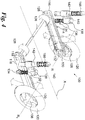
- Each rear wheel support assembly 114 is shown in Figures 4 and 5 .
- the rear wheel support assemblies 114 are located on either side of the rear of the chassis 102.
- Each rear wheel support assembly 114 comprises a swing arm 116 which is mounted on the side of the rear of the chassis 102.
- Each swing arm 116 is fixed at one end to a pivot bearing 118 in the chassis 102 so that each arm 116 is cantilevered from the chassis 102 and, furthermore, each arm 116 trails the chassis 102 and lies in a plane parallel to the longitudinal axis X-X of the vehicle 100.
- Each arm 116 is therefore a trailing swinging arm at the free end of which is rotatably mounted one of the rear wheels 108.
- a tyre 120 is carried by each of the rear wheels 108 and preferably has a round profile because each of the rear wheels 108 leans into a turn with the chassis 102, as will be discussed further below.
- Each of the trailing swinging arms 116 can pivot about its bearing 118 so that each rear wheel 108 can move up and down in an arc about the respective bearing 118 as shown by the block arrows in Figure 4 .
- a propulsion unit 122 (shown schematically in dotted lines in Figure 2 ) is located between the rear wheels 108 and, as such, enables the vehicle 100 to have a low centre of gravity. This assists the vehicle 100 by creating stability during cornering because one of the heaviest components of the vehicle 100 is located partly or entirely between (or at least close to) the axes R1, R2 of the rear wheels 108.
- the location of the propulsion unit 122 between the rear wheel support assemblies 114 and between the rear wheels 108 results in space-efficient packaging of the internal components of the vehicle 100.
- the propulsion unit 122 may be, for example, located beneath a passenger seat of the vehicle 100. The location of the propulsion unit 122 in this manner is possible because the tilting mechanism, unlike known arrangements, does not require any structural members or components to be located between the rear wheels 108 as will be described later.
- the propulsion unit 122 may take any suitable form; for example, as an internal combustion engine such as a petrol engine or diesel engine, an electric motor, or a so-called “hybrid engine” (being a combination of an internal combustion engine and an electric motor), is mounted in the chassis 102.
- an internal combustion engine such as a petrol engine or diesel engine
- an electric motor or a so-called “hybrid engine” (being a combination of an internal combustion engine and an electric motor)
- a so-called “hybrid engine” being a combination of an internal combustion engine and an electric motor
- the propulsion unit 122 drives the rear wheels 108.
- the propulsion unit 122 may also include a gearbox (not shown) which may be integral with the propulsion unit 122 (or engine) or may be located separately from the propulsion unit 122.
- the gearbox is located low down in the chassis 102 of the vehicle 102 in order to provide a low centre of gravity for the vehicle 100. It is also desirable for the gearbox to be located between the rear wheels 108 to provide a compact drive train arrangement.
- the propulsion unit 122 also comprises a power source 124 (shown schematically in dotted lines in Figure 2 ).
- the type of power source 124 utilised depends upon the type of propulsion unit 122 used in the vehicle 100.
- the power source 124 will take the form of a fuel tank and will desirably be located at the rear of the vehicle 100, such that at least a part of the fuel tank is located between the rear wheel support assemblies 114 or between the rear wheels 108.
- the power source 124 may comprise an array of batteries, for example lithium ion batteries.
- the batteries could be charged in any suitable fashion; for example, by an external power source such as the mains, or by on-board power sources such as a fuel cell or a "range-extender" type small internal combustion engine. Alternatively, a fuel cell may be utilised without a battery source if this is required.
- on-board power sources are used, then it is preferred that they are located towards the rear of the chassis 102, desirably such that a least a part of the power source 124 is located between the rear wheel support assemblies 114 or between the rear wheels 108.
- the drive from the propulsion unit 122 to the rear wheels 108 may be by any suitable means.
- an output from the propulsion unit 122 is connected to drive a horizontal transverse drive shaft 126 to each end of which is fixed front drive sprockets 128.
- the front drive sprockets 128 drive respective rear sprockets 130 mounted on each rear wheel 108 via a respective drive chain or belt 132.
- the axis of rotation of the horizontal drive shaft 126 is co-linear with the axes of the bearings 118 of the swing arms 116.
- each of the rear wheels 108 may be driven by a respective drive shaft running parallel to the swinging arm 116, each drive shaft being driven by the horizontal drive shaft 126.
- Each rear wheel support assembly 114 comprises a shock absorber 134 which is provided to control the vertical arcuate movement of each respective swinging arm 116.
- each shock absorber 134 has a coiled compression spring 136 to absorb the shock of the rear wheel 108 hitting a bump and a hydraulic damper 138 which damps compression and extension of the coil spring 136 in known manner.
- a gas-filled damper may alternatively be used.
- piezoelectric dampers may be used. These dampers utilise piezo-electric elements to lock the dampers when stationary. The piezo-electric material can also be constantly adjusted to change ride dynamics when the vehicle 100 is on the move.
- each shock absorber 134 An end of the hydraulic damper 138 of each shock absorber 134 is connected to its respective swinging arm 116.
- the other end 140 of each shock absorber 134 is rigidly connected to a housing 142 of a respective hydraulic cylinder 144 which also forms part of each rear wheel support assembly 114. As shown in Figure 4 , the other end of the hydraulic cylinder 144 is connected to the vehicle chassis 102.
- each hydraulic cylinder 144 has a central piston rod 146 which can moveable along an axis Y-Y relative to the housing 142.
- the lower end of the piston rod 146 has a piston head 148 which sealingly engages the internal wall of the housing 142 by means of an O-ring 150.
- the piston head 148 and O-ring 150 divides the hydraulic cylinder 144 into a first, upper chamber 152 and a second, lower chamber 154.
- the volumes of the upper and lower chambers 152, 154 vary as the piston rod 146 moves up and down.
- the volumes of the upper and lower chambers 152, 154 vary inversely proportionally, i.e.
- Hydraulic fluid 156 fills the whole of the upper and lower chambers 152, 154 of the hydraulic cylinder 144.
- the hydraulic fluid 156 may be a magnetorheological (MR) fluid such as Filisko.
- each swinging arm 116 is connected to the chassis 102 by means of the series connection of the hydraulic cylinder 144 and shock absorber 134 as well as by the bearing 118 about which the swinging arm 116 pivots.
- Each hydraulic cylinder 144 has an upper port 160 through the housing 142 to the upper chamber 152 and a lower port 162 through the housing 142 to the lower chamber 154.
- the upper port 160 of one hydraulic cylinder 144 is connected to the upper port 160 of the other hydraulic cylinder 144 by a flexible hose 164.
- the lower port 162 of each hydraulic cylinder 144 is connected to the lower port 162 of the other hydraulic cylinder 144 by a flexible hose 166. Therefore, a closed loop hydraulic circuit is formed by the flexible hoses 164, 166 and the hydraulic cylinders 144.
- the arrangement of the closed hydraulic loop using flexible hoses 164, 166 enables convenient packaging arrangements to be used in the vehicle 100.
- the space in the vehicle 100 between the rear wheels 108 and hydraulic cylinders 144 can be utilised for the propulsion unit 122 of the vehicle (see Figure 2 ) because the flexible hoses 164, 166 can be threaded around such parts of the vehicle 100.
- Each hydraulic cylinder 144 also has a coil spring 168 attached between the end 158 of the respective piston rod 148 and the housing 142.
- the coil spring 168 is arranged to provide a restoring force on each hydraulic cylinder 144. Thereby, in the absence of other forces, the coil springs 168 return the piston heads 148 within the hydraulic cylinders 144 to the same displacement position, naturally returning the vehicle 100 to the upright position.
- hydraulic fluid 156 is moved from either the upper chamber 152 or lower chamber 154 of a first hydraulic cylinder 144 to the corresponding upper or lower chamber 152, 154 of the second hydraulic chamber 144 via either flexible hose 164, 164. Since the hydraulic system is a closed loop and the hydraulic fluid 156 is substantially incompressible, then fluid will move back through the other of the flexible hoses 164, 166 back to the first hydraulic cylinder 144. This movement of hydraulic fluid 156, therefore, causes the piston heads 148 to move differentially in opposing directions and causing the vehicle to tilt with respect to the ground surface.
- the movement of the hydraulic fluid 156 can be accomplished in different ways.
- the preferred method depends upon the vehicle dynamic conditions, such as the vehicle speed, tilt angle, acceleration, cornering force or other suitable parameters.
- the tilting of the vehicle 100 must be handled automatically (for example, at high speed where human error may cause an accident) without direct user input to tilt the vehicle.
- user input for example, shifting of the user's body weight by leaning
- manoeuvre or steer the vehicle for example, when at low speed or when reversing/parking.
- the embodiment of the present invention is arranged to provide different modes of operation for tilting the vehicle.
- the driver is able to tilt the vehicle manually by manipulating his/her body weight.
- the driver of the vehicle 100 leans into the turn so as to shift his or her body weight laterally away from the longitudinal axis X-X of the vehicle 100 in the direction of the desired turn.
- the driver leans to the left.
- This transfer of body weight over the left side of the vehicle 100 causes the piston rod 146 of the left hand hydraulic cylinder 144 to depress, forcing hydraulic fluid 156 out of the lower chamber 154 of that hydraulic cylinder 144 through the lower hose 166 and into the lower chamber 154 of the right hand hydraulic cylinder 144.
- the extension of the right hand hydraulic cylinder 144 forces the right hand side of the chassis 102 upwards with the right hand swinging arm 116 pivoting relatively downwards about its bearing 118.
- the vehicle 100 leans by the appropriate amount, which is adjustable by the amount of lean of the driver, assisting the shift of body weight of the driver and also distributing the vehicle weight more evenly between the two rear wheels 108.
- the vehicle 100 can also be caused to lean by applying appropriate forces parallel to the longitudinal axis X-X to the control device such as a handlebar.
- the vehicle 100 can be caused to lean in a controllable manner entirely passively without the use of any active control system (such as computer or other electronic control) and without the heavy and complex semi-active lever linkages of some known arrangements, some of which require operation of foot pedals by the driver in order to cause the vehicle to lean.
- active control system such as computer or other electronic control
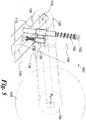
- the movement of the piston rod 146 in the housing 142 of the hydraulic cylinder 144 and the movement of the swing arm 116 is illustrated further in Figure 6 .
- the fully extended configuration of the hydraulic cylinder 144 is shown in the left-hand hydraulic cylinder 144 in Figure 6 and the fully compressed configuration of the hydraulic cylinder 144 is shown by the right-hand hydraulic cylinder 144 in Figure 6 .
- Figure 7 shows the vehicle 100 from the rear when leant over to the right for a right hand turn.
- the right hand hydraulic cylinder 144 is fully compressed so that the right hand side of the vehicle 100 tips downwards towards the ground.
- the left hand hydraulic cylinder 144 is fully extended, pushing the left hand side of the vehicle 100 upwards.
- the arrangement of the propulsion unit 122 and power source 124 low down in the chassis 102 assists in maintaining the centre of gravity of the vehicle 100 between the rear wheels 108. This is maintained irrespective of the angle of tilt of the chassis 102 of the vehicle 100, aiding stability of the vehicle 100 and preventing the vehicle 100 from toppling over in a turn.
- the stability of the vehicle 100 is further assisted by the location of at least a part of each of the propulsion unit 122 and power source 124 lies between the wheel assemblies 114 in both lateral and longitudinal directions, which aids stability.
- the centre of gravity should also be low down in the vehicle 100, preferably no more than 450 mm above the ground surface.
- the chassis 102 of the vehicle 100 is arranged to articulate or tilt.
- the angle of tilt ⁇ is measured relative to the upright, vertical position (shown by axis V-V in Figure 7 ) and the vehicle 100 can tilt up to and including an angle of 30 degrees away from the vertical, upright position V-V. This enables the vehicle 100 to turn sharply, whilst maintaining stability and engagement of the rear wheels 108 with the surface. Due to the inherent stability of the vehicle 100 afforded by the low centre of gravity, the angle ⁇ is much greater than that of known arrangements. However, other maximum angles of tilt ⁇ may be used as appropriate. For example, even though the vehicle 100 may be capable of higher angles of tilt, the vehicle 100 may be limited to a predefined, lower angle for safety purposes.
- the hydraulic arrangement of the present invention also has a second mode of operation.
- the tilting of the vehicle 100 is accomplished automatically and not by movement of the driver's body weight.
- Figure 8 illustrates a schematic diagram of a control arrangement 200 to achieve this.
- the control arrangement 200 comprises, for example, a microprocessor and is operable to control the hydraulic cylinders 144 and shock absorbers 134 to control the leaning of the vehicle.
- the control arrangement 200 controls a pump arrangement 202, a bypass valve 204, a valve 206 and damper controllers 208 associated with each shock absorber 134.
- first and second accelerometers 210, 212 are provided.
- the accelerometers 210, 212 may be located in any suitable place on the vehicle 100 and may communicate with the control arrangement through any suitable communication means, for example, wires or through wireless communication using, for example, a short range wireless network.
- the accelerometer 210 is preferably located on the steering arrangement 110 in order to provide the current position of the control device (such as a steering wheel or handlebars as shown in Figure 2 ) to the control arrangement 200.
- the control device such as a steering wheel or handlebars as shown in Figure 2
- wireless communication between the control arrangement 200 and the accelerometer 210 is beneficial to remove the need for wires between these components, reducing weight and mechanical wear.
- the control arrangement 200 also controls a steering arrangement lock out 214.
- the control arrangement 200 also has access to information such as vehicle speed (through, for example, a speedometer).
- the movement of hydraulic fluid 156 within the closed hydraulic loop and between each of the hydraulic cylinders 144 is controlled by the pump arrangement 202.
- the pump arrangement 202 is located in communication with the flexible hose 166.
- Other arrangements may be used. Any suitable type of pump may be used. However, a bidirectional pump; for example, a helical screw pump is preferred.
- the pump arrangement 202 may comprise more than one pump.
- the pump arrangement 202 is controlled by the control arrangement 200.
- bypass valve 204 Located in parallel with the pump arrangement 202 is a bypass valve 204.
- the bypass valve 204 may take any suitable form of valve which is at least bistable in nature, i.e it can be opened or closed. A variable-opening valve may also be used. An example of suitable valve may be a solenoid valve.
- the bypass valve 204 is controlled by the control arrangement 200. The bypass valve 204 is able to open in order to enable the vehicle to be operated in the first mode of operation, i.e. the vehicle can be tilted by movement of the driver's body laterally away from the longitudinal axis X-X.
- the pump arrangement 202 is bypassed and hydraulic fluid 156 is able to flow through the bypass valve 204.
- the control arrangement 200 selects the first mode of operation automatically when it is determined that the speed of the vehicle 100 is below a predetermined value, for example below 25 km/h, preferably below 15 km/h, more preferably below 5 km/h or when the vehicle is reversing.
- the steering arrangement lock out 214 is not engaged, and so the driver can steer the front wheel of the vehicle 100 using the control device 106. Also, at these speeds, the driver is able to steer the vehicle 100 safely by leaning to, for example, weave in and out of traffic or perform a reversing manoeuvre.
- the first mode of operation may be selectable by the driver and the second mode of operation will be the default mode of operation unless the first mode is explicitly selected by the driver by, for example, a button on the control device 106.
- control arrangement 200 operates the pump arrangement 202 to pump hydraulic fluid 156 in the appropriate direction to lean the vehicle 100 in the direction in which the driver intends to move (as indicated by the direction in which the driver moves the control device 106).
- the control arrangement also controls the valve 206.
- the valve 206 is located along the flow path of the other flexible hose 164 (although other arrangements may be used) and is configured to function as a lock to break the closed loop hydraulic fluid circuit. This is used to provide stability to the vehicle 100 when stationary. With the valve 206 open, hydraulic fluid 156 can flow between the hydraulic cylinders 144, allowing the vehicle 100 to be leant over as required. With the valve 206 closed, hydraulic fluid 156 cannot flow between the hydraulic cylinders 144, meaning that the angle of lean of the vehicle 100 is fixed.
- the vehicle 100 can be parked in a stable upright position.
- the vehicle 100 can even be parked upright on a cambered road by setting the amount of lean appropriately to take account of the lean before operating the valve 206.
- the valve 206 can be operated when the vehicle is moving at relatively high speed in order to prevent the vehicle from tipping at speed if desired.
- the control arrangement 200 may be configured to close the valve 206 when the vehicle parking brake (not shown) is applied.
- a switch (not shown), which may conveniently be mounted on or near the control device 106, can be operated to open or close the valve 206 as required.
- accelerometer arrangements could be used.
- a number of accelerometers could be used: a) To measure, in both first and second modes, when the vehicle has stopped b) to measure, in both first and second modes, the vehicle acceleration (in both forward and reverse directions); b) to sense up/down movements on the rear wheels such that the dampers could be automatically adjusted and/or c) to indicate or sound an alarm when the chassis 102 is close to, or reaches, the maximum 30 degree tilt.
- FIG. 9 An alternative construction 230 for the hydraulic cylinders and shock absorbers is shown in Figure 9 .
- the shock absorber 234 is integral with the hydraulic cylinder 244 and mounted internally of the housing 242 of the hydraulic cylinder 244 and, furthermore, provides the piston rod 246 of the hydraulic cylinder 244.
- the shock absorber 234 carries a piston head 248 at its end within the housing 242.
- the piston head 248 sealingly engages with the internal wall of the housing 242 by means of an O-ring 250.
- the housing 242 of the hydraulic cylinder 244 is connected to the chassis 102 and the piston rod 246 formed by the shock absorber 234 is connected to the swing arm 116.
- hydraulic fluid 256 is pumped out of the upper chamber 252 of the left hand hydraulic cylinder 244 to the upper chamber 252 of the right hand hydraulic cylinder 244 and from the lower chamber 254 of the right hand hydraulic cylinder 244 to the lower chamber 254 of the left hand hydraulic cylinder 244.
- the operation of the integral hydraulic cylinders 244 and shock absorbers 234 of Figure 9 is similar to that of the hydraulic cylinders 144 shown in Figure 6 and described above.
- An expansion tank (not shown) can be provided for the hydraulic fluid 256 with access to the expansion tank being provided to enable the hydraulic fluid 256 to be topped up as necessary.
- each swinging arm 116 for the rear wheels 108 is in two parts, a primary swing arm 280 and a secondary swing arm 281.
- the primary swing arm 280 is fixed at one end to the pivot bearing 282 in the chassis 102.
- the primary swing arm 280 is kinked upwards part way along its length by an angle of approximately 25°.
- a first end of the secondary swing arm 281 is pivotally connected to the primary swing arm 280 by a bearing 283 at the kink in the primary swing arm 280.
- the secondary swing arm 281 carries a rear wheel 284 at its other end.
- the shock absorber 285 is connected between the secondary swing arm 281 and the upwardly kinked portion (i.e.
- the hydraulic cylinder 286 is connected between the chassis 102 and the primary swing arm 280. Leaning of the vehicle 100 is achieved as described above. The driver moves his or her bodyweight over the side of the vehicle that is to move downwards with consequential pumping of hydraulic fluid between the hydraulic cylinders 286 and movement of the primary swing arm 280 relative to the chassis 102.
- a pump such as the pump arrangement 202 shown in Figure 8 , may be used.
- the shock absorbers 134; 285 may be damped using "Filisko" or similar Magnetorheological fluid, the viscosity of which can be adjusted by application of different electrical voltages.
- the shock absorbers 134; 285 in this case can be locked in position by passing an electrical charge through the Filisko damping fluid, further to increase stability when the vehicle 100 is stationary for example.
- the hydraulic fluid in the hydraulic cylinders 144; 286 may be "Filisko" or similar fluid, the viscosity of which can be adjusted by application of different electrical voltages.
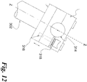
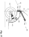
- Figures 11 and 12 show a possible arrangement of the front wheel of the vehicle 100 which is suitable for use with the control arrangement 200 of Figure 8 .
- Figure 11 shows a steering arrangement 300 which comprises a steering column 302, a kingpin 304 and a steering yoke 306.
- a front swing arm 308 is connected to the steering yoke 306 and the front swing arm is, in turn, connected to a front wheel 310 which is rotatably secured at an end thereof.
- a shock absorber 312 is connected between the front swing arm 308 and the steering yoke 306, i.e. in practice the shock absorber (or damper) 312 is connected between the front swing arm 308 and the chassis 102.
- the shock absorber 312 may optionally be controlled by a damper controller similar to that described above. As can be seen in Figure 9 , the centreline of the kingpin Z-Z passes forwardly of the centre of the front wheel 310. This enables the front wheel 310 to castor.
- a mechanism for disengaging the steering of the vehicle 100 to enable free to castor operation i.e. the first mode of operation
- a control device 314 in the form of a handlebar.
- the handlebar and the steering column 302 are interconnected by means of a locking pin 316 controlled by a sprung button 318.
- the button 318 optionally allows engagement/disengagement of the steering column 302 and handlebars.
- the locking pin 316 is also operable by a solenoid controlled by the control arrangement 200 in order to enable switching between the first mode of operation (in which the front wheel 310 is directly controllable by the control device 314), and the second mode of operation (in which the front wheel 310 and front swing arm 308 is free to castor and steering is accomplished by tilting of the chassis 102).
- the locking pin 316 is able to selectively engage/disengage the mechanical link between the steerable, pivotable front swing arm 308 and the control device 314.
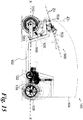
- Figure 13 shows an alternative arrangement of the front wheel of the vehicle 100 which is suitable for use with the control arrangement 200 of Figure 8 .
- Figure 13 shows a steering arrangement 400 which comprises a steering column 402, a kingpin 404 and a steering yoke 406.
- a front swing arm 408 is connected to the steering yoke 406 and the front swing arm is, in turn, connected to a front wheel 410 which is rotatably secured at an end thereof.
- a shock absorber 412 is connected between the front swing arm 408 and the steering yoke 406.
- the shock absorber 412 may optionally be controlled by a damper controller similar to that described above.
- the centreline of the kingpin Z1 passes forwardly of the centre of the front wheel 410. This enables the front wheel 410 to castor.
- steering of the vehicle is effected by means of a bevel gear 414 located at a distal end of the steering column 402 which engages with a complementary bevel gear 416 located on the yoke 406.
- the mechanical link between the front wheel 410 and the steering column 402 can be engaged or disengaged as required by means of a locking pin as described in relation to the previous embodiment.
- the steering linkage (comprising the bevel gears 414, 416) is located directly above the centreline of the wheel 410. However, this need not be so.
- the steering linkage may be located forwardly or rearwardly of the centreline of the wheel 410 as is required.
- bevel gears 414, 416 are shown in Figure 13 , alternative mechanisms such as a worm gear or rack and pinion may be used.
- the steering column 402 is operable to telescope back and forth along the axis Z2, the steering column can be adjusted to suit individual drivers.
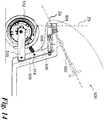
- Figure 14 shows a further alternative steering arrangement 500 suitable for use with the control arrangement 200 of Figure 8 .
- Figure 14 shows a steering arrangement 500 which comprises a steering column 502, a kingpin 504 and a steering yoke 506.
- the steering yoke 506 is conformally located adjacent a front part 508 of the vehicle body. This provides for a stronger and more reliable location of the yoke 506.
- the steering column 502 is in mechanical communication with the steering yoke 506 by means of a pair of bevel gears 516, 518.
- a rack and pinion system or a worm gear and follower.
- the proximity of the steering yoke 506 to the front part 510 of the vehicle body in this embodiment enables the addition of a pair of castor shimmy dampers 520 (only one of which is shown in Figure 14 ).
- Each castor shimmy damper 520 is connected between the front part 510 of the vehicle body and the steering yoke 506 and is arranged to prevent shimmy of the front wheel 512 when operating in a castoring mode.
- the castor shimmy damper 520 may be a spring.
- the castor shimmy dampers 520 may be replaced by a pair of hydraulic cylinders such as the cylinders 144 described with reference to the rear wheel arrangement.
- the hydraulic cylinders could be used to steer the vehicle in the first (manual counter steer) mode of operation, or as a failsafe mode should the bevel gear arrangement fail.
- springs may be provided on the hydraulic cylinder (similarly to earlier embodiments) to return the front wheel 512 of the vehicle to the centre.
- Figure 15 shows the steering arrangement 500 incorporated into a vehicle 100 similar to that shown in Figures 1 to 3 .
- the features shown in Figure 15 which are also shown in Figures 1 to 3 share the same reference numerals.
- the steering column 502 lies at an angle of between 10 - 15 degrees to the horizontal axis X-X. However, this may be adjustable to suit a particular driver. Additionally, the front swing arm 510 is able to pivot relative to the steering yoke 506 through an angle between 10 - 15 degrees relative to the horizontal axis X-X. This enables the vehicle 100 to traverse surface irregularities such as bumps or hills. The rear swing arms 116 are also able to pivot about their central axis at an angle of between 20 - 35 degrees either side of the horizontal axis X-X.
- the propulsion unit 122 is located at least partially between the rear wheels. This arrangement enables a low, rearward centre of gravity, improving the stability of the vehicle in a turn.
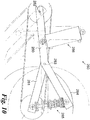
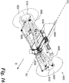
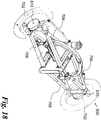
- FIG 16 shows an embodiment of a steering arrangement 600 in which two front wheels 602 are provided.
- the two front wheels 602 are able to steer, tilt and castor as for the previous steering arrangements 300, 400, 500 comprising only a single front wheel.
- the steering arrangement 600 comprises a central beam 604 which is arranged to rotate about an axis R1-R1 lying parallel to the axis X-X shown in Figure 1 .
- the central beam 604 is arranged to rotate with remainder of the chassis 102 of the vehicle 100, such that the vehicle 100 tilts in a turn.
- the forward direction of the vehicle is indicated by the arrow D.
- Attached to the central beam 604 are four A shaped-arms 606.
- Each A-arm comprises two rods joined at one end and connected to a common cross member at another end.
- Each A-arm forms a triangular member.
- A-arms 606 are located on opposing upper sides of the central beam 604 and are connected by hinges 608. A further two A-arms are hinged at opposing lower sides of the central beam 604. In other words, a pair of A-arms 606 extends away from each side of the central beam 604. A front wheel 602 is located at the distal end of each pair of A-arms 606. Each front wheel 602 is connected to each pair of A-arms 606 by a hub 610.
- each hub 610 could be incorporated into each hub 610 to drive the front wheels if required. Whilst this will result in additional mass located towards the front of the vehicle, the enhanced stability provided for by the four wheel arrangement mitigates the issues associated with this.
- a pair of damper arms 612 is provided. Each damper arm 612 is connected between the upper surface of the central beam 604 and both upper and lower respective A-arms 606. Each damper arm 612 comprises a connection rod portion 614 and a damper 616.
- the damper 616 is located substantially horizontally, with the connection rod portion 614 approximately perpendicular thereto and connected to the damper 616 by means of a pivot. When the central beam 604 is rotated, the connection rod portion 614 will also rotate with respect to the damper 616 about the pivot.
- the central beam 604 is also arranged to accommodate a steering column 618.
- the steering column 618 extends through the central beam 604 and is arranged to rotate about the axis R1-R1.
- a bevel gear 620 is located at a distal end of the steering column 618 and is arranged to steer the front wheels 602 by means of a complementary bevel gear 622 located on a central spindle 624.
- Linkage arms 626 are connected between the central spindle 624 and the wheel hubs 610, enabling rotation of the steering column 618 to steer the front wheels 602 when in the first mode of operation.
- the mechanical link between the steering column 618 and the wheels 602 can, optionally, be disengaged to enable the front wheels 602 to be free to castor, as is required in the second mode of operation.
- a bevel gear instead of a bevel gear, a worm gear, rack and pinion or hydraulic rams could be provided to effect steering of the vehicle.
- two steering arms one either side of the central beam 604, could be provided.
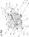
- FIG 17 shows a further alternative embodiment of a steering arrangement 700 in which two front wheels 702 are provided.
- the two front wheels 702 are able to steer, tilt and castor as for the previous steering arrangements 300, 400, 500 comprising only a single front wheel and steering arrangement 600 comprising two front wheels.
- the steering arrangement 700 comprises a central beam 704 which is arranged to rotate about an axis R2-R2 lying parallel to the axis X-X shown in Figure 1 .
- the central beam 704 is arranged to rotate with the remainder of the chassis 102 of the vehicle 100.
- the forward direction of the vehicle is indicated by the arrow D.
- A-arms 706 Attached to the central beam 704 are four A-arms 706. Two A-arms 706 are located on opposing upper sides of the central beam 704 and are connected by hinges 708. A further two A-arms 706 are hinged at opposing lower sides of the central beam 704. In other words, a pair of A-arms 706 extends away from each side of the central beam 704.
- a front wheel 702 is located at the distal end of each pair of A-arms 706.
- Each front wheel 702 is connected to each pair of A-arms 706 by a hub 710. Consequently, rotation of the central beam 704 with respect to the remainder of the chassis 102 will cause the upper and lower A-arms 706 to be displaced laterally, causing each hub 710 (and, thus, each wheel 702 attached thereto) to rotate about an axis parallel to the axis R2-R2. Thus, tilting of the wheels 702 can be effected in this manner.
- each hub 610 could be incorporated into each hub 610 to drive the front wheels if required. Whilst this will result in additional mass located towards the front of the vehicle, the enhanced stability provided for by the four wheel arrangement mitigates the issues associated with this.
- each damper arm 712 is connected between the middle side surface of the central beam 704 and only the lower respective A-arm 706.
- Each damper arm 712 comprises a connection rod portion 714 and a damper 716.
- the damper 716 is located substantially horizontally, with the connection rod portion 714 approximately perpendicular thereto and connected to the damper 716 by means of a pivot.
- the pivots of each damper arms 712 are connected by a curved linkage 718.
- the curved linkage 718 is divided into two portions connected by a central joint.
- the curved linkage 718 extends through the centre of the upper A-arms 706 and over and above the central beam 704. Whilst the linkage is described in this embodiment as being curved, this need not be so. The curved arrangement is useful for space efficiency; however, other arrangements could be used, for example, a straight linkage.
- dampers 712 to be mounted lower in the vehicle 100, lowering the centre of gravity of the vehicle 100 as a whole. Additionally, this arrangement reduces the unsprung mass of the vehicle. A low centre of gravity and low unsprung mass is important for a fully enclosed tilting vehicle to provide manoeuvrability, side wind stability and stability under braking.
- a steering column 720 extends above, and can be parallel to the central beam 704.
- the steering column 720 is arranged to rotate about the axis R3-R3 which is parallel to, and spaced from, the axis R2-R2.
- Steering of the vehicle is effected by means of a bevel gear or similar arrangement. This arrangement was described with reference to the previous embodiment and will not be described further here.
- Linkage arms 722 are connected between a central spindle 724 and the wheel hubs 710, enabling rotation of the steering column 720 to steer the front wheels 702 when in the first mode of operation.
- four linkage arms 722 i.e. two pairs. This option provides a failsafe mechanism in the event that the free to castor mode is engaged at high speed and a failure of the primary bevel gear or steering linkage occurs.
- the mechanical link between the steering column 720 and the wheels 702 can, optionally, be disengaged to enable the front wheels 602 to be free to castor, as is required in the second mode of operation. Free to castor operation is possible if the steering linkage arms 722 are located either forwardly or rearwardly of the centreline of the wheel hubs 710 in all options.
- FIG 18 shows a further alternative embodiment of a steering arrangement 800 in which two front wheels 802 are provided.
- the two front wheels 802 are able to steer, tilt and castor as for the previous steering arrangements 300, 400, 500 comprising only a single front wheel and steering arrangement 600, 700 comprising two front wheels.
- the steering arrangement 800 is substantially similar to the steering arrangement 700 of the previous embodiment. Therefore, components in common there between will not be described again here and will use the same reference numerals as for the previous embodiment.
- the steering arrangement 800 differs from the steering arrangement 700 in the provision of smaller and lighter wheel hubs 810.
- the wheel hubs 810 are smaller in diameter than the wheel hubs 710 of the previous embodiment and are connected to pivot hinges 812 attached to the A-arms 706. Additionally, only a single pair of linkage arms 722 is provided. However, the linkage arms 722 could again be duplicated in a failsafe mode. Additionally, the smaller diameter wheel hubs could also be used in the previous two front wheel arrangements described above.
- Figure 19 shows a simplified version of the embodiment of Figure 18 when in a turn on an uneven ground surface.
- a yet further embodiment of a steering arrangement 900 is illustrated schematically in Figure 20 .
- the steering arrangement 900 is substantially similar to the steering arrangements 700, 800 of the previous embodiments. Therefore, components in common there between will not be described again here and will use the same reference numerals as for the previous embodiments.
- the steering arrangement 900 differs from the previous two embodiments in the provision of an alternative central linking member. Instead of the curved linkage 718 of the previous embodiments, an arrangement comprising tensioned wires 918 and pulleys 920 is provided. This arrangement provides the necessary restoring forces but may be lighter weight than the semicircular linkage 718 of the previous two embodiments. Additionally, a pair of pulleys/wires may be provided to achieve failsafe operation.
- a yet further embodiment of a steering arrangement 950 is illustrated schematically in Figure 21 .
- the steering arrangement 950 is substantially similar to the steering arrangements 700, 800, 900 of the previous embodiments. Therefore, components in common there between will not be described again here and will use the same reference numerals as for the previous embodiments.
- the steering arrangement 950 differs from the previous embodiments in the provision of an alternative suspension and damper arrangement.
- the steering arrangement 950 comprises a pair of front hydraulic cylinders 952.
- the hydraulic cylinders 952 are structurally similar to the hydraulic cylinders 144 connected to the rear wheels of the vehicle 100 in earlier embodiments. Therefore, each hydraulic cylinder 952 comprises a movable piston (not shown) which divides each hydraulic cylinder 952 into two separate chambers.
- Each hydraulic cylinder 952 is connected at one end to the upper end central beam 704 by means of a pivotable connection 954, and at a lower end to a respective lower A-arm 706 as shown in Figure 21 .
- the two hydraulic cylinders 952 are fluidly connected at lower ends by means of a lower connection pipe 958 and at upper ends by means of an upper connection pipe 960. Therefore, the two hydraulic cylinders 952 are able to move oppositely and in unison as fluid is passed back and forth therebetween to effect tilting of the front wheel arrangement 950.
- the two hydraulic cylinders 952 could be linked with the rear hydraulic cylinders 144 to form a circuit of cylinders connecting the front and rear wheels. Additionally, the pump arrangement 202 could be used to control the operation of the front hydraulic cylinders 952 in addition to the rear hydraulic cylinders 144.
- a spring 962 (only one of which is shown in Figure 21 ) may be provided as a biasing means on the hydraulic cylinders 952 to provide a restoring force to the vehicle 100 in order to upright the body of the vehicle 100. This means that, in the absence of any other forces, the body of the vehicle 100 will return to the upright position.
- the above quadruple parallelogram arrangement of A-arms and curved linkage could also suitable for use in a conventional non-tilting four wheel vehicle, such as an automobile. Additionally, the above-described arrangement could also be suitable for a tilting two front wheel, one rear wheel vehicle or a tilting/non-tilting tractor or off-road quad bike.
- the above arrangements could be used to control the two front skis of a tilting or non-tilting snow mobile.
- the above examples could all have manual steer control.
- the vehicle 100 has three wheels only, the vehicle 100 could alternatively have four wheels with two wheels at the front and two wheels at the back as shown in earlier embodiments.
- each rear wheel could be driven by its own dedicated motor.
- the drive may be direct from the motor, in which case the motor can effectively form the swing arm.
- the drive may be indirect via a chain, belt or shaft, for example.
- the front wheel may optionally be driven from its own dedicated motor or from the motor or motors that drive the rear wheels.
Landscapes
- Engineering & Computer Science (AREA)
- Mechanical Engineering (AREA)
- Transportation (AREA)
- Chemical & Material Sciences (AREA)
- Combustion & Propulsion (AREA)
- General Engineering & Computer Science (AREA)
- Automation & Control Theory (AREA)
- Vehicle Body Suspensions (AREA)
- Automatic Cycles, And Cycles In General (AREA)
- Axle Suspensions And Sidecars For Cycles (AREA)
Applications Claiming Priority (2)
| Application Number | Priority Date | Filing Date | Title |
|---|---|---|---|
| GB1000244.2A GB2476807B (en) | 2010-01-08 | 2010-01-08 | A vehicle |
| PCT/GB2011/050018 WO2011083335A2 (en) | 2010-01-08 | 2011-01-07 | A vehicle |
Publications (2)
| Publication Number | Publication Date |
|---|---|
| EP2521659A2 EP2521659A2 (en) | 2012-11-14 |
| EP2521659B1 true EP2521659B1 (en) | 2020-09-02 |
Family
ID=41819071
Family Applications (1)
| Application Number | Title | Priority Date | Filing Date |
|---|---|---|---|
| EP11700575.1A Active EP2521659B1 (en) | 2010-01-08 | 2011-01-07 | A tilting vehicle and a method of tilting a vehicle with rear wheel supports having hydraulic cylinders communicating through a pump |
Country Status (5)
| Country | Link |
|---|---|
| US (1) | US9381785B2 (enExample) |
| EP (1) | EP2521659B1 (enExample) |
| JP (3) | JP2013516354A (enExample) |
| GB (2) | GB2476807B (enExample) |
| WO (1) | WO2011083335A2 (enExample) |
Families Citing this family (78)
| Publication number | Priority date | Publication date | Assignee | Title |
|---|---|---|---|---|
| JPS6447849A (en) * | 1987-08-11 | 1989-02-22 | Sekisui Chemical Co Ltd | Ceramic coating product and ceramic coating cutting tool |
| GB2476807B (en) | 2010-01-08 | 2012-10-31 | David Andrew Gale | A vehicle |
| DE102012201345A1 (de) * | 2011-01-31 | 2012-08-02 | Continental Teves Ag & Co. Ohg | Verfahren zur Unterstützung der Fahrzeugneigung eines mehrspurigen Fahrzeuges |
| GB2528608B (en) * | 2011-07-07 | 2016-04-27 | Andrew Gale David | A wheel support arrangement for a vehicle |
| GB201210713D0 (en) * | 2012-06-16 | 2012-08-01 | Wizz Mobility Ltd | Improvements in and relating to attendant propelled vehicles |
| JP6165857B2 (ja) * | 2012-07-10 | 2017-07-19 | ゴーテック・インターナショナル・リミテッド | 三輪自動車のための操舵および制御システム |
| USD695644S1 (en) * | 2012-08-09 | 2013-12-17 | GM Global Technology Operations LLC | Vehicle body exterior |
| DE102014201127B4 (de) | 2013-03-07 | 2022-02-03 | Ford Global Technologies, Llc | Seitlich neigbares, mehrspuriges Fahrzeug |
| DE102014201670A1 (de) | 2013-03-07 | 2014-09-11 | Ford Global Technologies, Llc | Seitlich neigbares, mehrspuriges Fahrzeug |
| DE102014201630B4 (de) | 2013-03-07 | 2021-09-02 | Ford Global Technologies, Llc | Seitlich neigbares, mehrspuriges Fahrzeug |
| DE102014201668B4 (de) | 2013-03-07 | 2021-09-02 | Ford Global Technologies, Llc | Seitlich neigbares, mehrspuriges Fahrzeug |
| DE102014201632B4 (de) * | 2013-03-07 | 2021-09-02 | Ford Global Technologies, Llc | Seitlich neigbares, mehrspuriges Fahrzeug |
| US9327725B2 (en) * | 2013-05-28 | 2016-05-03 | Eric N. Anderfaas | Geometry for improved driveline-suspension coupling of narrow leaning commuter vehicles |
| US9573435B2 (en) * | 2013-09-29 | 2017-02-21 | Elka Suspension Inc. | Dual inline hydraulic device |
| US9186951B2 (en) * | 2013-12-13 | 2015-11-17 | GM Global Technology Operations LLC | Height adjustable damping device |
| CN203876931U (zh) * | 2014-02-23 | 2014-10-15 | 于永飞 | 一种圆桶式电动自行车的转向装置 |
| CN104002902B (zh) * | 2014-05-07 | 2016-05-04 | 南通弗士特环保机械有限责任公司 | 三轮电动扫地车三轮联动转向机构 |
| JP6505136B2 (ja) * | 2014-06-20 | 2019-04-24 | クアドロ ヴィークルズ ソシエテ アノニム | 2個より多い車輪を有する車両のトリムの改良制御システム |
| MX2017000131A (es) * | 2014-07-04 | 2017-05-30 | Quadro Vehicles Sa | Dispositivo electronico de frenado del sistema de estabilidad de vehiculos con tres o mas ruedas inclinables. |
| DE102014217246B3 (de) | 2014-08-29 | 2015-12-24 | Ford Global Technologies, Llc | Stabilisierungsanordnung für ein Neigefahrwerk eines Fahrzeugs |
| DE102014217386B4 (de) | 2014-09-01 | 2024-11-14 | Ford Global Technologies, Llc | Verfahren zum Betrieb eines Neigefahrwerks für ein schienenungebundenes Fahrzeug |
| DE102014218492A1 (de) * | 2014-09-16 | 2016-03-17 | Zf Friedrichshafen Ag | Elektrohydraulischer Dämpfer |
| US9751374B2 (en) * | 2014-09-22 | 2017-09-05 | GM Global Technology Operations LLC | Vehicle and a height adjustment system for the vehicle |
| JP2016064790A (ja) * | 2014-09-25 | 2016-04-28 | 株式会社ショーワ | ステアリング装置 |
| US10076939B2 (en) | 2014-11-26 | 2018-09-18 | Ford Global Technologies, Llc | Suspension systems for laterally tiltable multitrack vehicles |
| US10023019B2 (en) | 2015-02-24 | 2018-07-17 | Ford Global Technologies, Llc | Rear suspension systems with rotary devices for laterally tiltable multitrack vehicles |
| US9925843B2 (en) | 2015-02-24 | 2018-03-27 | Ford Global Technologies, Llc | Rear suspension systems for laterally tiltable multitrack vehicles |
| JP6307695B2 (ja) * | 2015-03-06 | 2018-04-11 | 株式会社エクォス・リサーチ | 車両 |
| JP5952459B1 (ja) * | 2015-04-28 | 2016-07-13 | 摩特動力工業股▲ふん▼有限公司Motive Power Industry Co.,Ltd. | 車輪の懸垂機構 |
| WO2016187719A1 (en) * | 2015-05-26 | 2016-12-01 | Exonetik Inc. | Dynamic motion control system using magnetorheological fluid clutch apparatuses |
| US20170136874A1 (en) | 2015-08-23 | 2017-05-18 | Brian Harris | Off road vehicle |
| US20180065465A1 (en) | 2015-08-23 | 2018-03-08 | Arctic Cat Inc. | Off-Road Recreational Vehicle |
| JP6650714B2 (ja) * | 2015-09-28 | 2020-02-19 | ヤンマー株式会社 | 乗用車両 |
| US10317875B2 (en) * | 2015-09-30 | 2019-06-11 | Bj Services, Llc | Pump integrity detection, monitoring and alarm generation |
| FR3041925B1 (fr) * | 2015-10-02 | 2019-08-16 | Psa Automobiles Sa. | Vehicule leger modulaire |
| DE102015119638A1 (de) * | 2015-11-13 | 2017-05-18 | Hoerbiger Automotive Komfortsysteme Gmbh | Kraftfahrzeug-Fahrgestell |
| DE102015119637A1 (de) * | 2015-11-13 | 2017-05-18 | Hoerbiger Automotive Komfortsysteme Gmbh | Kraftfahrzeug-Fahrgestell |
| WO2017086350A1 (ja) * | 2015-11-20 | 2017-05-26 | ヤマハ発動機株式会社 | リーン車両 |
| EP3363723B1 (en) | 2015-11-20 | 2020-04-01 | Yamaha Hatsudoki Kabushiki Kaisha | Vehicle |
| CA3005803A1 (en) | 2015-11-20 | 2017-05-26 | Yamaha Hatsudoki Kabushiki Kaisha | Leaning vehicle |
| EP3378748B1 (en) | 2015-11-20 | 2023-08-09 | Yamaha Hatsudoki Kabushiki Kaisha | Leaning vehicle |
| FR3046571B1 (fr) * | 2016-01-11 | 2018-01-26 | Peugeot Citroen Automobiles Sa | Dispositif de gestion du roulis sur un vehicule automobile pendulaire |
| JP6603953B2 (ja) * | 2016-03-29 | 2019-11-13 | 株式会社エクォス・リサーチ | 車両 |
| DE102016212276A1 (de) | 2016-07-06 | 2018-01-11 | Robert Bosch Gmbh | Verfahren und Vorrichtung zur Dämpfung einer seitlichen Pendelbewegung bei einem einspurigen Kraftfahrzeug |
| WO2018011394A2 (de) * | 2016-07-15 | 2018-01-18 | Innovative Dragon Ltd. | Verkehrssystem, selbstfahrendes fahrzeug und steuerungsverfahren eines verkehrssystems |
| US10450027B2 (en) * | 2016-07-20 | 2019-10-22 | Coolryde B.V. | Golf-bag carrying vehicle |
| JP6557841B2 (ja) | 2016-08-29 | 2019-08-14 | 株式会社エクォス・リサーチ | 車両 |
| WO2018043408A1 (ja) | 2016-08-29 | 2018-03-08 | 国立大学法人 東京大学 | 車両 |
| CN108394479B (zh) * | 2017-02-07 | 2020-04-24 | 大行科技(深圳)有限公司 | 一种自平衡车辆装置及其相应控制方法 |
| JP2018140746A (ja) * | 2017-02-28 | 2018-09-13 | ヤマハ発動機株式会社 | 鞍乗型車両およびその組立方法 |
| JP2018172072A (ja) * | 2017-03-31 | 2018-11-08 | 株式会社エクォス・リサーチ | 車両 |
| IT201700083402A1 (it) | 2017-07-21 | 2019-01-21 | Ari Automotive Res Innovation S A S Di Francesca Bianco & C | Sospensione provvista di dispositivo reattivo ai carichi. |
| TWI615311B (zh) * | 2017-07-27 | 2018-02-21 | 光陽工業股份有限公司 | 具有防傾斜鎖定功能的車輛 |
| CN109367668A (zh) * | 2017-08-03 | 2019-02-22 | 光阳工业股份有限公司 | 具有防倾斜锁定功能的车辆 |
| US10053180B1 (en) * | 2017-08-31 | 2018-08-21 | Tower Trikes, Inc. | Trike steering and suspension systems |
| JP2019081476A (ja) | 2017-10-31 | 2019-05-30 | 株式会社エクォス・リサーチ | 車両 |
| US11028883B2 (en) | 2017-11-13 | 2021-06-08 | Arctic Cat Inc. | Off-road recreational vehicle |
| US20190184822A1 (en) * | 2017-12-18 | 2019-06-20 | Arctic Cat Inc. | Drive Configuration for Vehicle |
| US20210022292A1 (en) * | 2018-04-09 | 2021-01-28 | Vitirover | Robot and method for controlling the robot |
| WO2019204675A1 (en) | 2018-04-20 | 2019-10-24 | Pratt & Miller Engineering And Fabrication Inc. | Motor-vehicle with multi-mode extreme travel suspension -suspension hydraulic design |
| NL2020889B1 (en) * | 2018-05-08 | 2019-05-22 | Royalty Bugaboo Gmbh | Improved tilting suspension for a vehicle |
| JP6826348B2 (ja) * | 2018-06-04 | 2021-02-03 | ケイズ技研株式会社 | 多輪式車両 |
| CN109910588B (zh) * | 2019-03-28 | 2024-07-23 | 江阴戎辉机械设备制造有限公司 | 一种纯电动重型运输工程车 |
| US20200324598A1 (en) | 2019-04-13 | 2020-10-15 | WW Motorsports | Independent suspension system for a leaning vehicle |
| US11712925B2 (en) | 2019-07-01 | 2023-08-01 | Textron Inc. | Axial plunging half-shaft assembly |
| TR201912591A2 (tr) * | 2019-08-21 | 2021-03-22 | T C Erciyes Ueniversitesi | Bi̇r süspansi̇yon si̇stemi̇ |
| CN110588274A (zh) * | 2019-09-17 | 2019-12-20 | 亚帝发(上海)商贸有限公司 | 悬架系统、防侧倾装置和构成三轮车 |
| FR3109137B1 (fr) * | 2020-04-14 | 2022-05-06 | Paul Poggi | Vélo à deux roues motrices indépendantes |
| US11518042B2 (en) * | 2020-05-09 | 2022-12-06 | Ubtech Robotics Corp Ltd | Robotic assistant |
| CN114194289A (zh) * | 2020-09-17 | 2022-03-18 | 深圳市皓颢智能科技有限公司 | 一种双轮联动机构 |
| US11441638B2 (en) * | 2021-01-08 | 2022-09-13 | Sandcraft, Llc | Bump stop assembly |
| JP7588559B2 (ja) * | 2021-07-09 | 2024-11-22 | 本田技研工業株式会社 | 移動体 |
| CN113352878B (zh) * | 2021-07-21 | 2022-12-16 | 中国第一汽车股份有限公司 | 车辆辅助转向输入装置 |
| KR102362619B1 (ko) * | 2021-09-30 | 2022-02-14 | 주식회사 에이치제이모토 | 차동축과 틸팅회전축이 일직선상에 구비된 틸팅주행타입 다륜차량용 파워트레인의 구조 |
| JP2023068985A (ja) * | 2021-11-04 | 2023-05-18 | ヤマハ発動機株式会社 | 車両 |
| JP2024176242A (ja) * | 2023-06-08 | 2024-12-19 | 学校法人千葉工業大学 | 車両 |
| US20250058822A1 (en) * | 2023-08-18 | 2025-02-20 | Sameer Kolte | Mechatronic system for stable operation of a narrow-enclosed vehicle |
| TWI882679B (zh) * | 2024-02-05 | 2025-05-01 | 立淵機械股份有限公司 | 耦合機構及具有該耦合機構的電動三輪滑板車 |
Family Cites Families (60)
| Publication number | Priority date | Publication date | Assignee | Title |
|---|---|---|---|---|
| US2184202A (en) | 1937-12-28 | 1939-12-19 | Carl A Tschanz | Stabilizing system for vehicles |
| US2743941A (en) * | 1954-01-06 | 1956-05-01 | Walker Brooks | Automatic banking device for vehicles |
| DE1947232A1 (de) | 1969-09-18 | 1971-04-01 | Roessner Hans Dipl Ing | Hydropneumatischer Stossdaempfer mit Stabilisator-Wirkung |
| JPS4938318A (enExample) * | 1972-08-25 | 1974-04-10 | ||
| GB1561253A (en) | 1977-03-02 | 1980-02-13 | Trautwein W | Threewheeled vehicle |
| US4484648A (en) | 1979-06-29 | 1984-11-27 | Jephcott Edmund F | Ultra narrow enclosed motor vehicles |
| US4351410A (en) | 1980-07-17 | 1982-09-28 | Townsend Engineering Company | Self-balancing wheeled vehicle |
| AU1467183A (en) | 1982-06-02 | 1983-12-08 | Willem Van Der Horst | Suspension for 3/4 wheel vehicles |
| CA1248565A (en) * | 1984-02-25 | 1989-01-10 | Honda Giken Kogyo Kabushiki Kaisha (Also Trading As Honda Motor Co., Ltd .) | Suspension apparatus for vehicle |
| USRE32736E (en) * | 1984-04-20 | 1988-08-23 | Alignment system for vehicle load bed | |
| JPS61125973A (ja) * | 1984-11-21 | 1986-06-13 | 境 紀之 | 全車体が傾斜する三輪車 |
| JPH06455B2 (ja) * | 1985-04-05 | 1994-01-05 | 本田技研工業株式会社 | 車体傾動装置 |
| FR2611628B1 (fr) * | 1987-02-26 | 1990-11-30 | Bendix France | Correcteur de freinage asservi a la charge d'un vehicule |
| FR2646379B1 (fr) | 1989-04-26 | 1994-06-10 | Girardi Philippe | Dispositif hydraulique de commande de roulis d'un vehicule a trois roues inclinable |
| FR2654990B1 (fr) * | 1989-11-24 | 1992-03-27 | Sacem | Suspension pour vehicule a roues independantes. |
| JPH04100724A (ja) * | 1990-08-17 | 1992-04-02 | Nissan Motor Co Ltd | 車両用能動型スタビライザ |
| DE4035128A1 (de) | 1990-11-05 | 1992-06-17 | Ernst Dipl Ing Hoermann | Kurvenneigbares, mehrspuriges fahrzeug |
| JPH05213253A (ja) * | 1992-02-07 | 1993-08-24 | Suzuki Motor Corp | 後二輪用電動車両 |
| DE9414724U1 (de) | 1994-02-03 | 1994-11-24 | Huber, Ernst, 83549 Eiselfing | Fahrzeug mit Ausgleichsvorrichtung |
| CN1055268C (zh) * | 1994-06-14 | 2000-08-09 | 布林克斯韦斯特马斯公司 | 具有至少三个车轮自稳定并且方向可控的机动车 |
| AT403566B (de) | 1996-01-25 | 1998-03-25 | Geiser Friedrich | Motorisiertes fahrzeug, insbesondere dreirad, mit zwei drehbar am fahrzeugramen angelenkten, gefederten schwingen |
| JPH10264875A (ja) * | 1997-03-21 | 1998-10-06 | Suzuki Motor Corp | 後二輪自転車 |
| NL1007532C2 (nl) * | 1997-11-12 | 1999-05-17 | Brinks Westmaas Bv | Kantelvoertuig. |
| JPH11197191A (ja) | 1998-01-08 | 1999-07-27 | Hiroto Uenaka | 電動車椅子 |
| GB9802890D0 (en) | 1998-02-11 | 1998-04-08 | Rover Group | Vehicle suspensions |
| AU3083199A (en) * | 1998-03-16 | 1999-10-11 | Lawrence K. Edwards | Suspension and control system for leaning vehicle |
| EP1080005A1 (en) | 1998-05-27 | 2001-03-07 | Apax Vehicle Developments Inc. | Lightweight transportation vehicle |
| DE19844493A1 (de) | 1998-09-29 | 2000-03-30 | Zahnradfabrik Friedrichshafen | Hydropneumatisches Federungssystem |
| IT1313937B1 (it) * | 1999-11-17 | 2002-09-26 | Bruno Fedetto | Veicolo con stabilizzatore di posizione. |
| GB0002154D0 (en) * | 2000-02-01 | 2000-03-22 | Bamford Excavators Ltd | Working apparatus |
| CN100519240C (zh) | 2002-06-04 | 2009-07-29 | J·J·文·德尔·韦斯特赫伊曾 | 车辆的悬架系统 |
| DE10227417A1 (de) * | 2002-06-20 | 2004-02-19 | Zf Friedrichshafen Ag | Federungssystem für ein Fahrzeug |
| DE20217112U1 (de) * | 2002-10-31 | 2003-03-13 | Michaelsen, Hartwig, 10405 Berlin | Fahrzeuganhänger (PKW-Anhänger) mit absenkbarer Ladefläche |
| AU2002365106A1 (en) | 2002-12-20 | 2004-07-14 | Roald H. Pedersen | Vehicle with a titltable chassis |
| ITMI20040171A1 (it) * | 2004-02-04 | 2004-05-04 | Piaggio & C Spa | Dispositivo anti-rollio per veicoli |
| WO2005075278A1 (en) | 2004-02-06 | 2005-08-18 | Phillip Ronald James | Tilting vehicle |
| CN100509455C (zh) | 2004-02-13 | 2009-07-08 | 弗里德里克·盖泽 | 多轮辙弯道倾斜车辆以及用于使车辆倾斜的方法 |
| FR2872773B1 (fr) * | 2004-07-07 | 2006-09-29 | Moulene Sarl | Vehicule motorise de faible largeur |
| JP5166251B2 (ja) * | 2005-05-31 | 2013-03-21 | ブリンクス・ウェストマース・ビーブイ | 車両及び車両の傾斜を制御する方法 |
| US7487985B1 (en) | 2005-08-25 | 2009-02-10 | Robert Mighell | Tilting wheeled vehicle |
| TWI274677B (en) | 2005-12-01 | 2007-03-01 | Ind Tech Res Inst | Structure for enabling independently suspended wheels to lean with vehicle hull |
| US7665742B2 (en) | 2006-05-12 | 2010-02-23 | Haerr Timothy A | Vehicle hydraulic system |
| EP1870269B1 (en) | 2006-06-23 | 2008-09-17 | Fondazione Torino Wireless | A suspension tilting module for a wheeled vehicle and a wheeled vehicle equipped with said suspension tilting module |
| DE602006014031D1 (de) * | 2006-07-28 | 2010-06-10 | Marabese Design S R L | System zur steuerung des trimms von motorrädern mit drei oder vier rädern |
| EP2099624A1 (en) * | 2006-12-01 | 2009-09-16 | The Four Wheeled Motorcycle Company Limited | Suspension system |
| GB2444250A (en) * | 2006-12-01 | 2008-06-04 | Nicholas Richard Shotter | Hydraulic damper system for a leanable vehicle |
| CN201023543Y (zh) | 2007-01-25 | 2008-02-20 | 刘晓龙 | 一种新型电动三轮车 |
| EP2000336A1 (en) | 2007-06-07 | 2008-12-10 | Nederlandse Organisatie voor toegepast- natuurwetenschappelijk onderzoek TNO | Suspension system |
| US7954826B2 (en) * | 2007-06-18 | 2011-06-07 | Arvinmeritor Technology, Llc | Damper actuated active roll control |
| GB2450740A (en) * | 2007-07-05 | 2009-01-07 | Andrei Zavolnyi | Three-wheeled motor vehicle |
| TWI342839B (en) * | 2007-08-28 | 2011-06-01 | Anti-tilt apparatus and frame structure of tilt vehicle using the same | |
| ITMI20080018A1 (it) * | 2008-01-08 | 2009-07-09 | Marabese Design S R L | Sistema di pendolamento delle ruote per veicoli a tre o piu' ruote |
| FR2928130B1 (fr) | 2008-02-29 | 2010-05-28 | Moulene | Vehicule motorise a inclinaison commandee. |
| TWI354633B (en) * | 2008-08-05 | 2011-12-21 | Univ Nat Taiwan Science Tech | Motor vehicle and tilting mechanism thereof |
| US8123240B2 (en) * | 2009-07-10 | 2012-02-28 | Bombardier Recreational Products Inc. | Control system for leaning vehicle |
| US20110095494A1 (en) * | 2009-10-27 | 2011-04-28 | Dennis Joseph White | Hydraulic stabilizer |
| DE102009056105A1 (de) * | 2009-11-30 | 2010-06-24 | Daimler Ag | Wankstabilisierungssystem für ein Fahrzeug |
| GB2476807B (en) | 2010-01-08 | 2012-10-31 | David Andrew Gale | A vehicle |
| US8613340B2 (en) * | 2011-06-30 | 2013-12-24 | National Taiwan University Of Science And Technology | Anti-rollover motorized vehicle |
| GB2528608B (en) | 2011-07-07 | 2016-04-27 | Andrew Gale David | A wheel support arrangement for a vehicle |
-
2010
- 2010-01-08 GB GB1000244.2A patent/GB2476807B/en active Active
-
2011
- 2011-01-07 EP EP11700575.1A patent/EP2521659B1/en active Active
- 2011-01-07 GB GB1100226.8A patent/GB2476877B/en active Active
- 2011-01-07 WO PCT/GB2011/050018 patent/WO2011083335A2/en not_active Ceased
- 2011-01-07 US US13/520,889 patent/US9381785B2/en active Active
- 2011-01-07 JP JP2012547548A patent/JP2013516354A/ja active Pending
-
2016
- 2016-01-04 JP JP2016000212A patent/JP6538571B2/ja active Active
-
2019
- 2019-06-06 JP JP2019105853A patent/JP6920371B2/ja active Active
Non-Patent Citations (1)
| Title |
|---|
| None * |
Also Published As
| Publication number | Publication date |
|---|---|
| JP2013516354A (ja) | 2013-05-13 |
| EP2521659A2 (en) | 2012-11-14 |
| US9381785B2 (en) | 2016-07-05 |
| JP6920371B2 (ja) | 2021-08-18 |
| JP2019167099A (ja) | 2019-10-03 |
| GB201000244D0 (en) | 2010-02-24 |
| WO2011083335A2 (en) | 2011-07-14 |
| GB201100226D0 (en) | 2011-02-23 |
| GB2476877A (en) | 2011-07-13 |
| GB2476807A (en) | 2011-07-13 |
| GB2476877B (en) | 2017-01-18 |
| GB2476807B (en) | 2012-10-31 |
| WO2011083335A3 (en) | 2011-10-06 |
| JP2016074427A (ja) | 2016-05-12 |
| JP6538571B2 (ja) | 2019-07-03 |
| US20130068550A1 (en) | 2013-03-21 |
Similar Documents
| Publication | Publication Date | Title |
|---|---|---|
| EP2521659B1 (en) | A tilting vehicle and a method of tilting a vehicle with rear wheel supports having hydraulic cylinders communicating through a pump | |
| EP2729351B1 (en) | A vehicle | |
| EP3066001B1 (en) | Three-wheeled tilting bicycle | |
| US7722063B2 (en) | Vehicle suspension system | |
| US8645024B2 (en) | Motorized three-wheeled vehicle active suspension | |
| CN102596697B (zh) | 用于倾斜车辆的倾斜控制 | |
| US4487429A (en) | Tilting wheel vehicle suspension system | |
| US20080258415A1 (en) | Vehicle Lean and Alignment Control System | |
| JP2009509857A (ja) | 傾斜サスペンションマシン | |
| WO2010015986A1 (en) | Wheel tilting system with reduced crosswise dimensions for vehicles with three or more wheels | |
| US11801892B2 (en) | Vehicle with tilt frame and spring damper system | |
| US20060254841A1 (en) | Vehicle with adjustable axle system for actively maintaining stability | |
| EP1799472B1 (en) | Vehicle lean and alignment control system | |
| CN2133505Y (zh) | 三轮车的单转向轮的控制装置 | |
| CN112937238A (zh) | 一种非独立式悬架的窄车身全地形车 |
Legal Events
| Date | Code | Title | Description |
|---|---|---|---|
| PUAI | Public reference made under article 153(3) epc to a published international application that has entered the european phase |
Free format text: ORIGINAL CODE: 0009012 |
|
| 17P | Request for examination filed |
Effective date: 20120802 |
|
| AK | Designated contracting states |
Kind code of ref document: A2 Designated state(s): AL AT BE BG CH CY CZ DE DK EE ES FI FR GB GR HR HU IE IS IT LI LT LU LV MC MK MT NL NO PL PT RO RS SE SI SK SM TR |
|
| DAX | Request for extension of the european patent (deleted) | ||
| TPAC | Observations filed by third parties |
Free format text: ORIGINAL CODE: EPIDOSNTIPA |
|
| TPAC | Observations filed by third parties |
Free format text: ORIGINAL CODE: EPIDOSNTIPA |
|
| STAA | Information on the status of an ep patent application or granted ep patent |
Free format text: STATUS: EXAMINATION IS IN PROGRESS |
|
| 17Q | First examination report despatched |
Effective date: 20170508 |
|
| GRAP | Despatch of communication of intention to grant a patent |
Free format text: ORIGINAL CODE: EPIDOSNIGR1 |
|
| STAA | Information on the status of an ep patent application or granted ep patent |
Free format text: STATUS: GRANT OF PATENT IS INTENDED |
|
| RIC1 | Information provided on ipc code assigned before grant |
Ipc: B62K 5/10 20130101ALI20200228BHEP Ipc: B60G 21/00 20060101ALI20200228BHEP Ipc: B62K 25/18 20060101ALI20200228BHEP Ipc: B60G 17/015 20060101ALI20200228BHEP Ipc: B60G 17/005 20060101ALI20200228BHEP Ipc: B60G 3/14 20060101ALI20200228BHEP Ipc: F16F 9/22 20060101ALI20200228BHEP Ipc: B60G 17/016 20060101ALI20200228BHEP Ipc: B60G 21/073 20060101AFI20200228BHEP Ipc: B60G 7/00 20060101ALI20200228BHEP Ipc: B62D 9/02 20060101ALI20200228BHEP Ipc: B62K 5/027 20130101ALI20200228BHEP |
|
| INTG | Intention to grant announced |
Effective date: 20200318 |
|
| GRAS | Grant fee paid |
Free format text: ORIGINAL CODE: EPIDOSNIGR3 |
|
| GRAA | (expected) grant |
Free format text: ORIGINAL CODE: 0009210 |
|
| STAA | Information on the status of an ep patent application or granted ep patent |
Free format text: STATUS: THE PATENT HAS BEEN GRANTED |
|
| AK | Designated contracting states |
Kind code of ref document: B1 Designated state(s): AL AT BE BG CH CY CZ DE DK EE ES FI FR GB GR HR HU IE IS IT LI LT LU LV MC MK MT NL NO PL PT RO RS SE SI SK SM TR |
|
| REG | Reference to a national code |
Ref country code: GB Ref legal event code: FG4D |
|
| REG | Reference to a national code |
Ref country code: AT Ref legal event code: REF Ref document number: 1308434 Country of ref document: AT Kind code of ref document: T Effective date: 20200915 Ref country code: CH Ref legal event code: EP |
|
| REG | Reference to a national code |
Ref country code: DE Ref legal event code: R096 Ref document number: 602011068433 Country of ref document: DE |
|
| REG | Reference to a national code |
Ref country code: IE Ref legal event code: FG4D |
|
| REG | Reference to a national code |
Ref country code: LT Ref legal event code: MG4D |
|
| PG25 | Lapsed in a contracting state [announced via postgrant information from national office to epo] |
Ref country code: SE Free format text: LAPSE BECAUSE OF FAILURE TO SUBMIT A TRANSLATION OF THE DESCRIPTION OR TO PAY THE FEE WITHIN THE PRESCRIBED TIME-LIMIT Effective date: 20200902 Ref country code: HR Free format text: LAPSE BECAUSE OF FAILURE TO SUBMIT A TRANSLATION OF THE DESCRIPTION OR TO PAY THE FEE WITHIN THE PRESCRIBED TIME-LIMIT Effective date: 20200902 Ref country code: LT Free format text: LAPSE BECAUSE OF FAILURE TO SUBMIT A TRANSLATION OF THE DESCRIPTION OR TO PAY THE FEE WITHIN THE PRESCRIBED TIME-LIMIT Effective date: 20200902 Ref country code: FI Free format text: LAPSE BECAUSE OF FAILURE TO SUBMIT A TRANSLATION OF THE DESCRIPTION OR TO PAY THE FEE WITHIN THE PRESCRIBED TIME-LIMIT Effective date: 20200902 Ref country code: BG Free format text: LAPSE BECAUSE OF FAILURE TO SUBMIT A TRANSLATION OF THE DESCRIPTION OR TO PAY THE FEE WITHIN THE PRESCRIBED TIME-LIMIT Effective date: 20201202 Ref country code: NO Free format text: LAPSE BECAUSE OF FAILURE TO SUBMIT A TRANSLATION OF THE DESCRIPTION OR TO PAY THE FEE WITHIN THE PRESCRIBED TIME-LIMIT Effective date: 20201202 Ref country code: GR Free format text: LAPSE BECAUSE OF FAILURE TO SUBMIT A TRANSLATION OF THE DESCRIPTION OR TO PAY THE FEE WITHIN THE PRESCRIBED TIME-LIMIT Effective date: 20201203 |
|
| REG | Reference to a national code |
Ref country code: NL Ref legal event code: MP Effective date: 20200902 |
|
| REG | Reference to a national code |
Ref country code: AT Ref legal event code: MK05 Ref document number: 1308434 Country of ref document: AT Kind code of ref document: T Effective date: 20200902 |
|
| PG25 | Lapsed in a contracting state [announced via postgrant information from national office to epo] |
Ref country code: PL Free format text: LAPSE BECAUSE OF FAILURE TO SUBMIT A TRANSLATION OF THE DESCRIPTION OR TO PAY THE FEE WITHIN THE PRESCRIBED TIME-LIMIT Effective date: 20200902 Ref country code: LV Free format text: LAPSE BECAUSE OF FAILURE TO SUBMIT A TRANSLATION OF THE DESCRIPTION OR TO PAY THE FEE WITHIN THE PRESCRIBED TIME-LIMIT Effective date: 20200902 Ref country code: RS Free format text: LAPSE BECAUSE OF FAILURE TO SUBMIT A TRANSLATION OF THE DESCRIPTION OR TO PAY THE FEE WITHIN THE PRESCRIBED TIME-LIMIT Effective date: 20200902 |
|
| PG25 | Lapsed in a contracting state [announced via postgrant information from national office to epo] |
Ref country code: RO Free format text: LAPSE BECAUSE OF FAILURE TO SUBMIT A TRANSLATION OF THE DESCRIPTION OR TO PAY THE FEE WITHIN THE PRESCRIBED TIME-LIMIT Effective date: 20200902 Ref country code: SM Free format text: LAPSE BECAUSE OF FAILURE TO SUBMIT A TRANSLATION OF THE DESCRIPTION OR TO PAY THE FEE WITHIN THE PRESCRIBED TIME-LIMIT Effective date: 20200902 Ref country code: PT Free format text: LAPSE BECAUSE OF FAILURE TO SUBMIT A TRANSLATION OF THE DESCRIPTION OR TO PAY THE FEE WITHIN THE PRESCRIBED TIME-LIMIT Effective date: 20210104 Ref country code: NL Free format text: LAPSE BECAUSE OF FAILURE TO SUBMIT A TRANSLATION OF THE DESCRIPTION OR TO PAY THE FEE WITHIN THE PRESCRIBED TIME-LIMIT Effective date: 20200902 Ref country code: CZ Free format text: LAPSE BECAUSE OF FAILURE TO SUBMIT A TRANSLATION OF THE DESCRIPTION OR TO PAY THE FEE WITHIN THE PRESCRIBED TIME-LIMIT Effective date: 20200902 Ref country code: EE Free format text: LAPSE BECAUSE OF FAILURE TO SUBMIT A TRANSLATION OF THE DESCRIPTION OR TO PAY THE FEE WITHIN THE PRESCRIBED TIME-LIMIT Effective date: 20200902 |
|
| PG25 | Lapsed in a contracting state [announced via postgrant information from national office to epo] |
Ref country code: AL Free format text: LAPSE BECAUSE OF FAILURE TO SUBMIT A TRANSLATION OF THE DESCRIPTION OR TO PAY THE FEE WITHIN THE PRESCRIBED TIME-LIMIT Effective date: 20200902 Ref country code: AT Free format text: LAPSE BECAUSE OF FAILURE TO SUBMIT A TRANSLATION OF THE DESCRIPTION OR TO PAY THE FEE WITHIN THE PRESCRIBED TIME-LIMIT Effective date: 20200902 Ref country code: IS Free format text: LAPSE BECAUSE OF FAILURE TO SUBMIT A TRANSLATION OF THE DESCRIPTION OR TO PAY THE FEE WITHIN THE PRESCRIBED TIME-LIMIT Effective date: 20210102 Ref country code: ES Free format text: LAPSE BECAUSE OF FAILURE TO SUBMIT A TRANSLATION OF THE DESCRIPTION OR TO PAY THE FEE WITHIN THE PRESCRIBED TIME-LIMIT Effective date: 20200902 |
|
| REG | Reference to a national code |
Ref country code: DE Ref legal event code: R097 Ref document number: 602011068433 Country of ref document: DE |
|
| PG25 | Lapsed in a contracting state [announced via postgrant information from national office to epo] |
Ref country code: SK Free format text: LAPSE BECAUSE OF FAILURE TO SUBMIT A TRANSLATION OF THE DESCRIPTION OR TO PAY THE FEE WITHIN THE PRESCRIBED TIME-LIMIT Effective date: 20200902 |
|
| PLBE | No opposition filed within time limit |
Free format text: ORIGINAL CODE: 0009261 |
|
| STAA | Information on the status of an ep patent application or granted ep patent |
Free format text: STATUS: NO OPPOSITION FILED WITHIN TIME LIMIT |
|
| 26N | No opposition filed |
Effective date: 20210603 |
|
| PG25 | Lapsed in a contracting state [announced via postgrant information from national office to epo] |
Ref country code: MC Free format text: LAPSE BECAUSE OF FAILURE TO SUBMIT A TRANSLATION OF THE DESCRIPTION OR TO PAY THE FEE WITHIN THE PRESCRIBED TIME-LIMIT Effective date: 20200902 Ref country code: DK Free format text: LAPSE BECAUSE OF FAILURE TO SUBMIT A TRANSLATION OF THE DESCRIPTION OR TO PAY THE FEE WITHIN THE PRESCRIBED TIME-LIMIT Effective date: 20200902 Ref country code: SI Free format text: LAPSE BECAUSE OF FAILURE TO SUBMIT A TRANSLATION OF THE DESCRIPTION OR TO PAY THE FEE WITHIN THE PRESCRIBED TIME-LIMIT Effective date: 20200902 |
|
| REG | Reference to a national code |
Ref country code: CH Ref legal event code: PL |
|
| PG25 | Lapsed in a contracting state [announced via postgrant information from national office to epo] |
Ref country code: LU Free format text: LAPSE BECAUSE OF NON-PAYMENT OF DUE FEES Effective date: 20210107 |
|
| REG | Reference to a national code |
Ref country code: BE Ref legal event code: MM Effective date: 20210131 |
|
| PG25 | Lapsed in a contracting state [announced via postgrant information from national office to epo] |
Ref country code: IT Free format text: LAPSE BECAUSE OF FAILURE TO SUBMIT A TRANSLATION OF THE DESCRIPTION OR TO PAY THE FEE WITHIN THE PRESCRIBED TIME-LIMIT Effective date: 20200902 |
|
| PG25 | Lapsed in a contracting state [announced via postgrant information from national office to epo] |
Ref country code: LI Free format text: LAPSE BECAUSE OF NON-PAYMENT OF DUE FEES Effective date: 20210131 Ref country code: CH Free format text: LAPSE BECAUSE OF NON-PAYMENT OF DUE FEES Effective date: 20210131 |
|
| PG25 | Lapsed in a contracting state [announced via postgrant information from national office to epo] |
Ref country code: IE Free format text: LAPSE BECAUSE OF NON-PAYMENT OF DUE FEES Effective date: 20210107 |
|
| PG25 | Lapsed in a contracting state [announced via postgrant information from national office to epo] |
Ref country code: BE Free format text: LAPSE BECAUSE OF NON-PAYMENT OF DUE FEES Effective date: 20210131 |
|
| PG25 | Lapsed in a contracting state [announced via postgrant information from national office to epo] |
Ref country code: HU Free format text: LAPSE BECAUSE OF FAILURE TO SUBMIT A TRANSLATION OF THE DESCRIPTION OR TO PAY THE FEE WITHIN THE PRESCRIBED TIME-LIMIT; INVALID AB INITIO Effective date: 20110107 Ref country code: CY Free format text: LAPSE BECAUSE OF FAILURE TO SUBMIT A TRANSLATION OF THE DESCRIPTION OR TO PAY THE FEE WITHIN THE PRESCRIBED TIME-LIMIT Effective date: 20200902 |
|
| PG25 | Lapsed in a contracting state [announced via postgrant information from national office to epo] |
Ref country code: MK Free format text: LAPSE BECAUSE OF FAILURE TO SUBMIT A TRANSLATION OF THE DESCRIPTION OR TO PAY THE FEE WITHIN THE PRESCRIBED TIME-LIMIT Effective date: 20200902 |
|
| PG25 | Lapsed in a contracting state [announced via postgrant information from national office to epo] |
Ref country code: TR Free format text: LAPSE BECAUSE OF FAILURE TO SUBMIT A TRANSLATION OF THE DESCRIPTION OR TO PAY THE FEE WITHIN THE PRESCRIBED TIME-LIMIT Effective date: 20200902 |
|
| PG25 | Lapsed in a contracting state [announced via postgrant information from national office to epo] |
Ref country code: MT Free format text: LAPSE BECAUSE OF FAILURE TO SUBMIT A TRANSLATION OF THE DESCRIPTION OR TO PAY THE FEE WITHIN THE PRESCRIBED TIME-LIMIT Effective date: 20200902 |
|
| PGFP | Annual fee paid to national office [announced via postgrant information from national office to epo] |
Ref country code: GB Payment date: 20241125 Year of fee payment: 15 |
|
| PGFP | Annual fee paid to national office [announced via postgrant information from national office to epo] |
Ref country code: FR Payment date: 20241209 Year of fee payment: 15 |
|
| PGFP | Annual fee paid to national office [announced via postgrant information from national office to epo] |
Ref country code: DE Payment date: 20241126 Year of fee payment: 15 |