EP2509051B1 - Media processing device - Google Patents
Media processing device Download PDFInfo
- Publication number
- EP2509051B1 EP2509051B1 EP10813094.9A EP10813094A EP2509051B1 EP 2509051 B1 EP2509051 B1 EP 2509051B1 EP 10813094 A EP10813094 A EP 10813094A EP 2509051 B1 EP2509051 B1 EP 2509051B1
- Authority
- EP
- European Patent Office
- Prior art keywords
- medium
- link member
- bills
- drive motor
- dispensing
- Prior art date
- Legal status (The legal status is an assumption and is not a legal conclusion. Google has not performed a legal analysis and makes no representation as to the accuracy of the status listed.)
- Not-in-force
Links
- 230000007246 mechanism Effects 0.000 claims description 66
- 230000033001 locomotion Effects 0.000 claims description 8
- 230000008878 coupling Effects 0.000 claims description 6
- 238000010168 coupling process Methods 0.000 claims description 6
- 238000005859 coupling reaction Methods 0.000 claims description 6
- 230000002093 peripheral effect Effects 0.000 claims description 6
- 238000000151 deposition Methods 0.000 description 97
- 230000005540 biological transmission Effects 0.000 description 41
- 101100492805 Caenorhabditis elegans atm-1 gene Proteins 0.000 description 33
- 238000010586 diagram Methods 0.000 description 13
- 239000002184 metal Substances 0.000 description 11
- 230000009471 action Effects 0.000 description 4
- 238000005452 bending Methods 0.000 description 4
- 238000001514 detection method Methods 0.000 description 4
- 230000001771 impaired effect Effects 0.000 description 4
- 238000003780 insertion Methods 0.000 description 4
- 230000037431 insertion Effects 0.000 description 4
- 238000005266 casting Methods 0.000 description 2
- 230000000694 effects Effects 0.000 description 2
- 238000012986 modification Methods 0.000 description 2
- 230000004048 modification Effects 0.000 description 2
- 230000009467 reduction Effects 0.000 description 2
- 229920003002 synthetic resin Polymers 0.000 description 2
- 239000000057 synthetic resin Substances 0.000 description 2
- 238000004891 communication Methods 0.000 description 1
- 238000009499 grossing Methods 0.000 description 1
- 230000004044 response Effects 0.000 description 1
Images


Classifications
-
- G—PHYSICS
- G07—CHECKING-DEVICES
- G07F—COIN-FREED OR LIKE APPARATUS
- G07F19/00—Complete banking systems; Coded card-freed arrangements adapted for dispensing or receiving monies or the like and posting such transactions to existing accounts, e.g. automatic teller machines
- G07F19/20—Automatic teller machines [ATMs]
- G07F19/203—Dispensing operations within ATMs
-
- G—PHYSICS
- G07—CHECKING-DEVICES
- G07F—COIN-FREED OR LIKE APPARATUS
- G07F19/00—Complete banking systems; Coded card-freed arrangements adapted for dispensing or receiving monies or the like and posting such transactions to existing accounts, e.g. automatic teller machines
-
- G—PHYSICS
- G07—CHECKING-DEVICES
- G07D—HANDLING OF COINS OR VALUABLE PAPERS, e.g. TESTING, SORTING BY DENOMINATIONS, COUNTING, DISPENSING, CHANGING OR DEPOSITING
- G07D11/00—Devices accepting coins; Devices accepting, dispensing, sorting or counting valuable papers
- G07D11/10—Mechanical details
- G07D11/14—Inlet or outlet ports
-
- G—PHYSICS
- G07—CHECKING-DEVICES
- G07D—HANDLING OF COINS OR VALUABLE PAPERS, e.g. TESTING, SORTING BY DENOMINATIONS, COUNTING, DISPENSING, CHANGING OR DEPOSITING
- G07D13/00—Handling of coins or of valuable papers, characterised by a combination of mechanisms not covered by a single one of groups G07D1/00 - G07D11/00
Definitions
- the present invention relates to a medium processing apparatus for handing over a leaf shaped medium to a user.
- Such types of medium processing apparatus include, for example, automated teller machines (referred to below as “ATMs”) for depositing and dispensing bills (banknotes), serving as a leaf shaped medium, and installed in branches of financial institutions, convenience stores, gasoline stands, supermarkets and the like.
- ATMs automated teller machines
- banknotes serving as a leaf shaped medium
- ATMs there are some ATMs configured to, in a dispensing transaction, collect dispensing bills in a money depositing and dispensing port, this being a medium handover port, open a shutter of the money depositing and dispensing port, and also raise dispensing bills so as to externally expose the dispensing bills from the money depositing and dispensing port in order to facilitate removal of the dispensing bills by a user.
- Such a bill raising means is, for example, configured as described in Patent Document 1 and Patent Document 2.
- Patent Document 1 Japanese Patent Application Laid-Open (JP-A) No. 9-221239
- JP-A Japanese Patent Application Laid-Open
- a gripped state is adopted with a press plate pressed against dispensing bills by using a parallel link mechanism, and the dispensing bills are raised together with the bottom plate in this state by forward rotating the timing belt.
- the ATM When dispensing bills have not been removed from the depositing and dispensing port for a specific duration or longer, the ATM emits an alarm nose at the periphery of the depositing and dispensing port, prompting the user to remove the dispensing bills.
- the user in cases where a user is, for example, an elderly person, someone with impaired hearing, or the like, the user sometimes cannot hear the alarm sound or falters in their response.
- the ATM determines that the dispensing bills have been left behind, and forgotten dispensing bill processing is performed. In such cases, the ATM reverse rotates the belt (for example, the timing belt in Patent Document 1 or the conveying belt in Patent Document 2), lowering the dispensing bills. The ATM thereby houses the dispensing bills inside the depositing and dispensing port.
- the ATM shuts the shutter of the depositing and dispensing port, and conveys the dispensing bills from inside the depositing and dispensing port to a removal forgotten cassette within the machine, and stores the dispensing bills in the forgot cassette as forgotten bills.
- the present invention is made to address the issue described above, and has an object of providing a bill processing apparatus that can reduce the frequency of occurrences of forgetting to remove a leaf shaped medium.
- the present invention is a medium processing apparatus for performing handover of a leaf shaped medium to a user, the medium processing apparatus including: a medium handover port where the medium is handed over; and a medium handover port mechanism comprising a support member for moving the medium up and down inside the medium handover port in a state in which the medium is placed on the support member, and an elongated link member that has a pivot point and is provided with a first end side connected to the support member and extending in directions different at the first end side and the other end side of the link member, and a rotation member with peripheral edge portion engaging with the other end side of the link member, raising and lowering the other end side of the link member due to rotation thereof, and thereby raising and lowering the other side of the link member, and a drive motor that rotationally drives the rotation member, wherein when the medium is placed on the support member, the drive motor rotates in one direction to raise the support member, and when the medium is removed, the drive motor rotates in said one direction to lower the support member
- the medium handover port mechanism provided to the medium processing apparatus successively raises and lowers the leaf shaped medium inside the medium handover port.
- the medium processing apparatus can thereby notify the user of the position of the leaf shaped medium by a visible action, even if the user is, for example, an elderly person, someone with impaired hearing, or the like. Consequently, the medium processing apparatus can reduce the frequency of occurrences of forgetting to remove the leaf shaped medium.
- the medium processing apparatus preferably also emits an alarm sound, and can thereby ensure that the user is notified of the position of the leaf shaped medium. Consequently, the frequency of occurrences of forgetting to remove the leaf shaped medium can be further reduced.
- a bill processing apparatus can be provided that can reduce the frequency of occurrences of forgetting to remove a leaf shaped medium (such as, for example, bills).
- the conventional bill raising means when performing forgotten bill processing, in order to lower the bills from the raised state of the bills, control is required to switch of the rotation direction of the drive motor. Accordingly, the conventional bill raising means cannot achieve a smooth bill lowering operation.
- the present invention (1) reduces the number of configuration components from those of conventional bill raising means, realizing a reduction in cost, and also (2) enables bill raising operation and lowering operation without switching over the rotation direction of the drive motor, simplifying rotation control of the drive motor and having a supplementary object of providing a handover mechanism for realization of a smooth bill lowering operation.
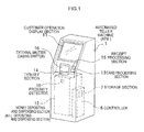
- Fig. 1 and Fig. 2 are drawings respectively illustrating an overall configuration of a medium processing apparatus according to an exemplary embodiment.
- Fig. 1 illustrates the external configuration of the medium processing apparatus according to the present exemplary embodiment
- Fig. 2 illustrates the main internal configuration of the medium processing apparatus.
- an ATM is employed as the medium processing apparatus
- bills dispenser bills
- a bill depositing and dispensing port mechanism is employed as the medium handover port mechanism.
- An ATM 1 is installed in a branch of a financial institution, a convenience store, a gasoline stand, a supermarket or the like and is a machine for depositing and dispensing bills as the leaf shaped medium.
- the ATM 1 is connected via a communication line to a host computer, not shown in the drawings, maintained and controlled by a financial institution.
- the host computer has customer data stored on a storage device, not shown in the drawings, such as user account numbers and names, residual saving balance data and the like.
- the ATM 1 includes a controller 6, a storage section 7, a proximity detector 10, a customer operation display section 11, a money depositing and dispensing section 12, a card processing section 13, a ten-key section 14, a receipt processing section 15, and a casing shutter 16.
- the ATM 1 also includes a bill mechanism shutter 17, a depositing and dispensing port 18, a cassette section 21, a temporary holding section 22, an examination section 23, a conveying path 24, a bill depositing and dispensing port mechanism 30, and pool guides 31a, 31b.
- the controller 6 is control means for controlling the operation of each of the sections of the ATM 1.
- the controller 6 is configured by a CPU.
- the controller 6 has an interface section that acts as a connection port with a host computer.
- the storage section 7 is storage means for storing various control programs and data.
- the storage section 7 is configured by RAM and a ROM, hard disk or the like.
- the proximity detector 10 is detection means for detecting a user approaching the ATM 1.
- the customer operation display section 11 displays various information related to transaction processing, and is a configuration element by which operation data is input by a user.
- the customer operation display section 11 is equipped with a transaction guidance display section for providing a customer with various information related to transaction processing, and a touch panel disposed on the surface of the transaction guidance display section for operation data to be input by a customer.
- the money depositing and dispensing section 12 is a configuration element for handling money. Explanation here is of a case in which the money is bills M, serving as the leaf shaped medium.
- the money depositing and dispensing section 12 is referred to below as the "bill depositing and dispensing section 12".
- the card processing section 13 is reading means for reading a code set for each financial institution and customer data, such as customer account number, name and the like, from a customer identification card (cashing card or the like).
- the card processing section 13 is disposed inside of a card insertion and return opening provided on the front side of the ATM 1.
- the ATM 1 When a customer inserts a cashing card into the card insertion and return opening, the ATM 1 draws the cashing card inside and reads customer data with the card processing section 13. When a transaction has been completed, the ATM 1 returns the cashing card to the card insertion and return opening, for return to the customer.
- the ten-key section 14 is input means for inputting a PIN number and the like.
- the customer inputs the PIN number by operating the ten-key section 14 according to instructions on a transaction progress screen displayed on the customer operation display section 11.
- the ten-key section 14 may be provided to the customer operation display section 11.
- the ten-key section 14 is preferably provided substantially horizontally in a position obscured by the body of the customer so that input operation of PIN numbers and the like by the customer can be prevented from being seen by a third party standing behind the customer.
- the receipt processing section 15 is printing means for printing a transaction receipt slip.
- the casing shutter 16 and the bill mechanism shutter 17 are shutters respectively provided at the periphery of the depositing and dispensing port 18.
- the casing shutter 16 is a shutter provided to the casing
- the bill mechanism shutter 17 is a shutter provided within the casing.
- the casing shutter 16 is referred to below as the “external shutter” and the bill mechanism shutter 17 is referred to below as the “internal shutter 17".
- the external shutter 16 is for protecting the internal shutter 17.
- the external shutter 16 is opened and closed by being swung in the arrow A direction shown in Fig. 2 , by a motor or the like, not shown in the drawings.
- the controller 6 controls opening and closing operation of the external shutter 16 according to detection data from the sensor.
- the internal shutter 17 restricts introduction by a customer of bills M for depositing processing (referred to below as “depositing bills M”) in the depositing and dispensing port 18, and removing of bills M for dispensing processing (referred to below as “dispensing bills M” from the depositing and dispensing port 18.
- the internal shutter 17 opens and closes by being slid in the arrow B direction shown in Fig. 2 by a motor, not shown in the drawings.
- a sensor not shown in the drawings, is disposed at the periphery of the internal shutter 17 for detecting the open-closed position of the internal shutter 17.
- the controller 6 controls the opening and closing operation of the internal shutter 17 according to sensor data from this sensor.
- the depositing and dispensing port 18 is a medium handover port employed for handing over the leaf shaped medium to and from a customer.
- the depositing and dispensing port 18 is provided at an inclined angle such that the user side (the ATM 1 front side thereof) is lower, and the ATM 1 rear side thereof is higher.
- the depositing and dispensing port 18 adopts a state enabling introduction of the depositing bills M by the external shutter 16 and the internal shutter 17 adopting an open state.
- the ATM 1 draws the depositing bills M into the bill depositing and dispensing section 12.
- the dispensing bills M are collected in the depositing and dispensing port 18 during a dispensing transaction or the like, and, by the external shutter 16 and the internal shutter 17 adopting an open state, the depositing and dispensing port 18 adopts a state enabling the dispensing bills M to be removed.
- the bill depositing and dispensing port mechanism 30 successively performs an operation to raise the dispensing bills M so that they are externally exposed from the depositing and dispensing port 18, and an operation to lower the dispensing bills M to house the dispensing bills M inside the depositing and dispensing port 18.
- the ATM 1 uses a visible action to notify a user of the position of the dispensing bills M, and to also prompt the user to remove the dispensing bills M.
- the cassette section 21 is a holding store for holding the bills M separately by denomination.
- the temporary holding section 22 is a holding store for temporarily holding the bills M during depositing and dispensing transactions.
- the examination section 23 is a configuration element for performing authenticity examination and counting of the bills M during depositing and dispensing transactions.
- the conveying path 24 is conveying means for conveying the bills M to each of the sections.
- the bill depositing and dispensing port mechanism 30 is a mechanism for lifting up the leaf shaped medium inside the medium handover port (in this case the depositing and dispensing port 18).
- the bill depositing and dispensing port mechanism 30 successively raises and lowers the dispensing bills M inside the depositing and dispensing port 18 during a dispensing transaction.
- the pool guides 31a, 31b are respective guide members provided exposed at the inside of the depositing and dispensing port 18 for supporting the leaf shaped medium.
- the pool guide 31a is provided on the ATM 1 front side, and the pool guide 31b is provided at the ATM 1 rear side.
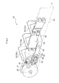
- Fig. 3 illustrates a configuration of the medium handover port mechanism as viewed from the rear side.
- Fig. 4 illustrates the configuration of the medium handover port mechanism as viewed from the front side.
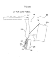
- Fig. 5 illustrates the configuration of the medium handover port mechanism as viewed from the side.
- the bill depositing and dispensing port mechanism 30 is, similarly to the depositing and dispensing port 18, provided at an inclined angle, such that the user side (the front side) thereof is lower and the ATM 1 rear side thereof is higher.
- the bill depositing and dispensing port mechanism 30 includes a bracket 32, a slider 33, a link member 35, a drive motor 36, a drive gear 37, and a transmission gear 38.
- the bracket 32 is a support member for supporting each member, such as the link member 35, the drive motor 36, the transmission gear 38 and the like.
- the link member 35 is attached to the bracket 32 such that the link member 35 pivots about a pivot point portion 51, described later.
- a first end side of the link member 35 is coupled to the slider 33 by a coupling portion 55, described later, and the other end side of the link member 35 is coupled to a rotation member (in this case the transmission gear 38) by a drive bearing portion 52, described later.
- the drive motor 36 is attached to the bracket 32 such that the drive gear 37 attached to the rotation shaft of the drive motor 36 meshes with the transmission gear 38.
- the transmission gear 38 is attached to the bracket 32 such that the transmission gear 38 rotates in a parallel state to the drive bearing portion 52, described later, of the link member 35.
- the bracket 32 is formed in a shape such that the portion of the bracket 32 positioned at the periphery of the slider 33 is displaced backwards to the rear side (see Fig. 2 ), and the portion of the bracket 32 positioned at the periphery of the drive motor 36, the drive gear 37, and the transmission gear 38 projects out to the front side (see Fig. 2 ).
- the portion formed projecting out is referred to below as the "projecting portion”, and the portion formed displaced backwards is referred to as the “rearward portion”, with the portion connecting together the projecting portion and the rearward portion referred to as the “side portion”.
- An opening is provided in the side portion of the bracket 32 for the link member 35 to pass through.
- the link member 35 is attached at the front side of the rearward portion of the bracket 32 with the pivot point portion 51, described later.
- the link member 35 is disposed passing through from the front side to the rear side of the bracket 32 due to the link member 35 passing through the opening provided in the side portion of the bracket 32.
- the drive motor 36, the drive gear 37 and the transmission gear 38 are attached at the rear side of the projecting portion of the bracket 32. Driving force from the drive motor 36 is transmitted to the link member 35 by the link member 35 engaging the transmission gear 38 with the drive bearing portion 52, described later.
- the slider 33 is a support member for supporting the leaf shaped medium.
- the slider 33 is connected to the drive motor 36 through the link member 35, the transmission gear 38 and the drive gear 37.
- the slider 33 successively moves with the leaf shaped medium being placed thereon up and down inside the medium handover port by the rotation shaft of the drive motor 36 rotating in one direction (direction Aa shown in Fig. 3 ).
- the slider 33 is configured equipped with three locations (referred to below as "support portions") 33a, 33b, 33c for supporting the bills M.
- the slider 33 is configured using two sheet metal plates.
- the right hand side support portion 33a and the left hand side support portion 33c are formed by bending and folding the first sheet metal plate.
- the central support portion 33b is formed by bending and folding the second sheet metal plate.
- the slider 33 is then formed by attaching the second sheet metal plate at substantially the center of the first sheet metal plate.
- the support member 33 is configured by integrally forming the support portions 33a, 33b, 33c, for example by casting.
- the slider 33 may also be configured by a synthetic resin, such as a plastic or the like, as long as sufficient strength can be secured.
- Raising and lowering rollers 42 are provided at both flanks of the slider 33.
- the raising and lowering rollers 42 are members for smoothing raising and lowering motions performed by the slider 33.
- the raising and lowering rollers 42 make contact with two rails (slider shafts), not shown in the drawings, provided along the top-bottom direction at the periphery of the slider 33.
- the slider 33 slides in the top-bottom direction along the two rails by the raising and lowering rollers 42 rotating over the surface of the two rails.
- the raising and lowering rollers 42 may be configured, as shown in Fig. 6 , with a configuration in which the raising and lowering rollers 42 are fixed, rotatably, to the bracket 32 by raising and lowering roller rotation shafts 43 alone.
- Fig. 6 is an enlarged cross-section of one of the raising and lowering rollers 42.
- the thus configured raising and lowering rollers 42 smooth the raising and lowering motions of the slider 33 by rotating during raising and lowering motions of the slider 33.
- the link member 35 is a long plate shaped member, connected at a first end side to the slider 33, and provided extending along a different direction at the first end side and at the other end side.
- the link member 35 is configured with a raising and lowering portion 53 at the first end side for raising and lowering the slider 33, and the drive bearing portion 52 at the other end side for taking driving force from the drive motor 36.
- the link member 35 is equipped at the raising and lowering portion 53 with the coupling portion 55 rotatably connected to the slider 33.
- the link member 35 is also provided with an elongated hole 54 in the drive bearing portion 52 for slidably supporting a transmission roller 39, described later, of the transmission gear 38.
- the elongated hole 54 is formed elongated along the extending direction of the drive bearing portion 52, so as to encompass the moving range of the transmission roller 39.
- a substantially central portion of the link member 35 is provided with the pivot point portion 51 that is rotatably connected to the bracket 32, and the drive bearing portion 52 and the raising and lowering portion 53 perform raising and lowering motions by pivoting about the pivot point portion 51.
- the link member 35 is preferably configured by a metal plate in order to secure sufficient strength.
- the drive motor 36 is drive means for rotationally driving the transmission gear 38.
- the drive gear 37 is a gear for meshing with the transmission gear 38, and is attached to the rotation shaft of the drive motor 3 6.
- the transmission gear 38 is a rotation member that rotates parallel to the drive bearing portion 52 of the link member 35.
- the transmission gear 38 rotates due to receipt of driving force from the drive motor 36 through the drive gear 37.
- a peripheral edge portion of the transmission gear 38 is equipped with a transmission roller 39.
- the transmission roller 39 is a protruding portion that protrudes out towards the drive bearing portion 52 of the link member 35.
- the transmission gear 38 engages with the drive bearing portion 52 of the link member 35 due to insertion of the transmission roller 39 into the elongated hole 54 of the drive bearing portion 52 of the link member 35. Accordingly, the transmission gear 38 transmits driving force from the drive motor 36 to the link member 35.
- the transmission gear 38 may be attached to the rotation shaft of the drive motor 36. In such a case, a configuration is adopted in which the transmission gear 38 rotates on direct receipt of driving force from the drive motor 36, rather than through the drive gear 37.
- the controller 6 of the ATM 1 actuates the drive motor 36 of the bill depositing and dispensing port mechanism 30, and thereby rotating the rotation shaft of the drive motor 36 in one direction (direction Aa shown in Fig. 3 ).
- the drive gear 37 meshed with the transmission gear 38 is attached to the rotation shaft of the drive motor 36. Accordingly, the transmission gear 38 rotates in the opposite direction to that of the rotation shaft of the drive motor 36 (direction Ab shown in Fig. 3 ).
- the transmission roller 39 is provided at the peripheral edge portion of the transmission gear 38, and the transmission roller 39 is inserted into the elongated hole 54 of the drive bearing portion 52 of the link member 35. Accordingly, the transmission roller 39 slides inside the elongated hole 54, accompanying the rotation of the transmission gear 38 in the opposite direction to that of the rotation shaft of the drive motor 36 (direction Ab shown in Fig. 3 ).
- the link member 35 pivots about the pivot point portion 51 such that the drive bearing portion 52 raises and lowers in direction Ac shown in Fig. 3 , and the raising and lowering portion 53 raises and lowers in the opposite direction to the direction of motion of the drive bearing portion 52.
- the bill depositing and dispensing port mechanism 30 successively raises and lowers the slider 33 and the bills M placed on the slider 33 by rotating the drive motor 36 in one direction (direction Aa shown in Fig. 3 ).
- the bill depositing and dispensing port mechanism 30 is not equipped with a mechanism and/or belt, roller or the like for gripping the bills M. Consequently, the bills M are lifted up in an unrestrained state (namely, in a free state, not restrained by any member).
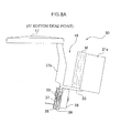
- Figs. 7 to Figs. 9 are respective diagrams illustrating operation of the medium handover port mechanism according to the present exemplary embodiment.
- Figs. 7 show the operation of the medium handover port mechanism as seen from the rear side.
- Fig. 7A shows the slider 33 in a state when positioned at the bottom dead point and Fig. 7B shows the slider 33 in a state when positioned at the top dead point.
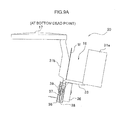
- Figs. 8 and Figs. 9 show operation of the medium handover port mechanism as seen from the side.
- Figs. 8 shows operation when dispensing comparatively lots of bills M
- Figs. 9 shows operation when dispensing comparatively few bills M (a single bill in the illustrated example).
- Fig. 8A and Fig. 9A show the slider 33 in a state when positioned at the bottom dead point and Fig. 8B and Fig. 9B show the slider 33 in a state when positioned at the top dead point.
- the bill depositing and dispensing port mechanism 30 pre-disposes the slider 33 at the bottom dead point, as shown in Fig. 7A and Fig. 8A .
- positional control of the slider 33 here is, for example, performed by the controller 6 based on output of a position detection sensor, not shown in the drawings, for detecting the position of the transmission roller 39.
- the controller 6 determines that the slider 33 is positioned at the bottom dead point, and when the transmission roller 39 is in the state shown in Fig. 7B , the controller 6 determines that the slider 33 is positioned at the top dead point.
- the controller 6 preferably monitors the rotation angles of the transmission gear 38 and the drive motor 36, and controls rotation of the drive motor 36 such that the slider 33 is stopped at the bottom dead point or the top dead point.
- the ATM 1 starts a dispensing transaction when instructed to perform a dispensing transaction as the transaction processing by a customer, such as through operation of the customer operation display section 11, and when the withdrawal amount has also been input.
- the controller 6 of the ATM 1 actuates the bill depositing and dispensing section 12, and causes the bills M stored in the cassette section 21 to be examined by the examination section 23.
- the controller 6 also collects the bills M determined by the examination section 23 to be dispensable, collecting the number of bills corresponding to the withdrawal amount above the slider 33 inside the depositing and dispensing port 18.
- the controller 6 starts opening of the external shutter 16 and the internal shutter 17 provided at the periphery of the depositing and dispensing port 18.
- the controller 6 actuates the drive motor 36 of the bill depositing and dispensing port mechanism 30, rotating the rotation shaft of the drive motor 36 in one direction (direction Aa shown in Fig. 3 ).
- the controller 6 thereby raises the slider 33 and the bills M placed on the slider 33.
- the controller 6 temporarily stops the drive motor 36.
- the controller 6 then monitors the state of removal of the bills from the output of a bill detection sensor, not shown in the drawings, provided inside the depositing and dispensing port 18.
- the controller 6 When detected that the customer has removed the bills M, the controller 6 actuates the drive motor 36, and rotates the rotation shaft of the drive motor 36 in the same direction as when raising the slider 33 (direction Aa shown in Fig. 3 ). The controller 6 thereby lowers the slider 33. When the slider 33 has been lowered to the position of bottom dead point (see Fig. 7A and Fig. 8A ) the controller 6 stops the drive motor 36. The controller 6 then closes the external shutter 16 and the internal shutter 17 provided at the periphery of the depositing and dispensing port 18. The ATM 1 thereby completes the dispensing processing.
- the controller 6 causes an alarm sound prompting the user to remove the bills M to be emitted from speakers, not shown in the drawings, provided at the periphery of the depositing and dispensing port 18, up until a predetermined duration for bill removal (referred to below as the “bill removal duration”) has elapsed.
- the controller 6 also actuates the drive motor 36 to rotate the rotation shaft of the drive motor 36 in one direction (direction Aa shown in Fig. 3 ) until the elapsed time has reached the bill removal duration.
- the bill depositing and dispensing port mechanism 30 successively performs an operation raising the dispensing bills M and externally exposing the dispensing bills M from the depositing and dispensing port 18, and an operation lowering the dispensing bills M and housing the dispensing bills M inside the depositing and dispensing port 18.
- the ATM 1 when there is a question as to whether or not the bills M have been forgotten, the ATM 1 notifies the user of the position of the dispensing bills M and prompts the user to remove the dispensing bills M using a visible action. Consequently, the ATM 1 can reduce the frequency of occurrences of forgetting to remove the dispensing bills M.
- controller 6 controls to vary the rotation speed of the drive motor 36.
- controller 6 may be configured so as to broadcast an announcement prompting removal of the bills M, such as "Please take the bills M" or the like, from speakers, not shown in the drawings, provided at the periphery of the depositing and dispensing port 18.
- the controller 6 lowers the slider 33 and the bills M placed on the slider 33.
- the controller 6 stops the drive motor 36.
- the controller 6 then closes the external shutter 16 and the internal shutter 17 provided at the periphery of the depositing and dispensing port 18, the bill depositing and dispensing section 12 stores the bills M placed on the slider 33 in a removal forgotten cassette, not shown in the drawings.
- the ATM 1 thereby completes dispensing processing.
- the controller 6 closes the external shutter 16 and the internal shutter 17 quickly, and the bill depositing and dispensing section 12 stores the bills M placed on the slider 33 in the removal forgotten cassette, not shown in the drawings.
- the ATM 1 thereby completes dispensing processing.
- the bill depositing and dispensing port mechanism 30 may be continuously driven for a multiple of the drive duration required for one to-and-fro raising and lowering motion. Due to the ATM 1 performing plural cycles of raising and lowering the bills M without interruption, the attention of the customer can be attracted to both the position of bills M and to removing of the bills M when there is a question as to whether or not removing of the bills M has been forgotten.
- the ATM 1 can attract the attention of the customer to the position of the bills M and to removing the bills M using a visible action, forgetting to remove the bills M can be efficiently prevented.
- the controller 6 controlling so as to vary the rotation speed of the drive motor 36, the raising and lowering motions of the bills M can be gradually speeded up, and the attention attracting effect can be enhanced. Furthermore, in the ATM 1, by broadcasting at the same time an announcement urging removal of the bills M, such as "Please take the bills M" or the like with the speakers, not shown in the drawings, provided at the periphery of the depositing and dispensing port 18, forgetting to remove the bills M can be even more efficiently prevented.
- the bill depositing and dispensing port mechanism 30 is provided at an inclined angle so as to be lower at the user side (the front side) and higher at the ATM 1 rear side. Accordingly, by raising and lowering the bills M, the bill depositing and dispensing port mechanism 30 can present the bills M in an unrestrained state (namely, in a free state, not restrained by any member) further towards the customer nearside of the apparatus.
- the bill depositing and dispensing port mechanism 30 when the bill depositing and dispensing port mechanism 30 is dispensing comparatively lots of the bills M, the bills M are in a state collected at the customer nearside of the apparatus, and the bills M can be dispensed in this state.
- the bill depositing and dispensing port mechanism 30 when the bill depositing and dispensing port mechanism 30 is dispensing comparatively few of the bills M (a single bill in the illustrated example), even suppose, for example, the bill(s) M were initially adhered to the inside of the depositing and dispensing port 18 (an in particular at the far side of the apparatus), the bills M are raised and lowered, shaking the bills M. The bills M can thereby be separated from the inside of the depositing and dispensing port 18. As a result, as shown in Fig. 9B , the bill depositing and dispensing port mechanism 30 can achieve a state in which the bills M are tilted over to the customer nearside of the apparatus, and can dispense the bill in such a state.
- the ATM 1 can dispense the bills M in a state facilitating removal.
- the frequency with which removal of a leaf shaped medium is forgotten can be reduced by successively raising and lowering the leaf shaped medium.
- this medium processing apparatus since the components of conventional bill raising means for realizing an operation to grip bills and an operation to raise bills in a gripped state become unnecessary, the number of configuration components can be reduced compared to in the conventional bill raising means, and cost can be reduced in comparison to the conventional bill raising means.
- the medium processing apparatus since there is no discrimination made during rotation control between forward rotation and reverse rotation of the drive motor 36, configuration may be made such that the drive motor 36 is driven in a single direction for a specific duration. Consequently, according to this medium processing apparatus, simple rotation control of the drive motor 36 can be realized, without the need for rotation direction switching, and smooth bills M raising and lowering operations can also be achieved.
- the medium processing apparatus when dispensing comparatively lots of the bills M, the bills M adopt a state collected together at the customer nearside of the apparatus, and the bills M can be dispensed in such a state.
- the medium processing apparatus when dispensing comparatively few bills M, even suppose the bills M were initially adhered to the inside of the depositing and dispensing port 18 (particularly at the far side of the apparatus), the bills M can be separated from the inside of the depositing and dispensing port 18 by raising and lowering the bills M. Consequently, according to the medium processing apparatus, the bills M can be dispensed in a state facilitating removal.
- the medium handover port mechanism 30 is not limited to employing bills, and application may be made to any desired device performing handover of a medium to a user, such as a ticket issuing machine or the like.
- bracket 32 and the slider 33 are not limited to those of the illustrated example, and appropriated modifications can be adopted.
- the slider 33 employs two sheet metal plates, with the right hand side support portion 3 3 a and the left hand side support portion 33c formed by bending and folding the first sheet metal plate, and the central support portion 33b formed by bending and folding the second sheet metal plate. The slider 33 is then formed by attaching the second sheet metal plate substantially at the centre of the first sheet metal plate.
- configuration of the slider 33 may be made with each of the support portions 33a, 33b, 33c integrally formed, for example by casting.
- configuration may be made with the slider 33 configured from a synthetic resin, such as a plastic or the like.
- configuration is made such that driving force of the drive motor 36 is transmitted to the rotation member 38 through the drive gear 37 and the transmission gear 38.
- configuration may be made such that the rotation force of the drive motor 36 is transmitted to the rotation member 38 through another gear(s) in addition to the drive gear 37 and the transmission gear 38.
- configuration may be made such that the rotation member 38 is attached to the rotation shaft of the drive motor 36 and driving force from the drive motor 36 is directly transmitted thereto.
Landscapes
- Physics & Mathematics (AREA)
- General Physics & Mathematics (AREA)
- Business, Economics & Management (AREA)
- Accounting & Taxation (AREA)
- Finance (AREA)
- Financial Or Insurance-Related Operations Such As Payment And Settlement (AREA)
- Sheets, Magazines, And Separation Thereof (AREA)
Applications Claiming Priority (2)
| Application Number | Priority Date | Filing Date | Title |
|---|---|---|---|
| JP2009270933A JP5471366B2 (ja) | 2009-11-30 | 2009-11-30 | 媒体処理装置 |
| PCT/JP2010/061420 WO2011065049A1 (ja) | 2009-11-30 | 2010-07-05 | 媒体処理装置 |
Publications (3)
| Publication Number | Publication Date |
|---|---|
| EP2509051A1 EP2509051A1 (en) | 2012-10-10 |
| EP2509051A4 EP2509051A4 (en) | 2013-08-21 |
| EP2509051B1 true EP2509051B1 (en) | 2014-10-08 |
Family
ID=44066153
Family Applications (1)
| Application Number | Title | Priority Date | Filing Date |
|---|---|---|---|
| EP10813094.9A Not-in-force EP2509051B1 (en) | 2009-11-30 | 2010-07-05 | Media processing device |
Country Status (6)
| Country | Link |
|---|---|
| US (1) | US8448856B2 (enExample) |
| EP (1) | EP2509051B1 (enExample) |
| JP (1) | JP5471366B2 (enExample) |
| KR (1) | KR101513963B1 (enExample) |
| CN (1) | CN102257537B (enExample) |
| WO (1) | WO2011065049A1 (enExample) |
Families Citing this family (6)
| Publication number | Priority date | Publication date | Assignee | Title |
|---|---|---|---|---|
| JP5518923B2 (ja) * | 2012-03-06 | 2014-06-11 | 東芝テック株式会社 | 紙幣出金装置 |
| JP5891957B2 (ja) * | 2012-06-01 | 2016-03-23 | 沖電気工業株式会社 | 媒体繰出収納装置及び媒体処理装置 |
| JP5849860B2 (ja) * | 2012-06-05 | 2016-02-03 | 沖電気工業株式会社 | 自動取引装置、及び自動取引方法 |
| JP6303921B2 (ja) * | 2014-08-25 | 2018-04-04 | 沖電気工業株式会社 | 媒体取引装置 |
| JP2016133966A (ja) * | 2015-01-19 | 2016-07-25 | 沖電気工業株式会社 | 媒体引渡装置及びシャッタ開閉機構 |
| CN107274551A (zh) * | 2017-08-16 | 2017-10-20 | 深圳怡化电脑股份有限公司 | 一种纸币临时收集装置及自动交易装置 |
Family Cites Families (14)
| Publication number | Priority date | Publication date | Assignee | Title |
|---|---|---|---|---|
| JP2763192B2 (ja) * | 1990-10-30 | 1998-06-11 | 沖電気工業株式会社 | 紙幣入出金装置の紙幣集積方法 |
| JPH09221239A (ja) | 1996-02-15 | 1997-08-26 | Omron Corp | 駆動力伝達装置および紙幣入出金装置 |
| JP3318206B2 (ja) * | 1996-07-19 | 2002-08-26 | 株式会社三協精機製作所 | 自動取引装置 |
| JP2693749B2 (ja) * | 1996-08-02 | 1997-12-24 | 株式会社東芝 | 自動取引装置 |
| GB2365610A (en) * | 2000-08-02 | 2002-02-20 | Ncr Int Inc | Self-service terminal |
| JP4815064B2 (ja) | 2001-05-07 | 2011-11-16 | マミヤ・オーピー株式会社 | 紙幣入出金装置 |
| JP3996831B2 (ja) * | 2002-09-27 | 2007-10-24 | 日立オムロンターミナルソリューションズ株式会社 | 媒体取扱装置 |
| JP4631391B2 (ja) * | 2004-10-27 | 2011-02-16 | 沖電気工業株式会社 | 紙幣入出金装置 |
| JP4579651B2 (ja) * | 2004-11-05 | 2010-11-10 | 富士通株式会社 | 自動取引装置 |
| JP4631834B2 (ja) * | 2006-09-08 | 2011-02-16 | マックス株式会社 | 用紙積載装置及び製本装置 |
| JP4889456B2 (ja) * | 2006-11-24 | 2012-03-07 | 日立オムロンターミナルソリューションズ株式会社 | 紙幣入出金装置および紙幣入出金装置制御方法 |
| DE102007056998A1 (de) * | 2007-11-27 | 2009-05-28 | Giesecke & Devrient Gmbh | Vorrichtung für die Annahme und Ausgabe von Banknoten |
| US8276901B2 (en) * | 2008-03-26 | 2012-10-02 | Glory Ltd. | Paper sheet handling apparatus and paper sheet handling method |
| JP5269164B2 (ja) * | 2010-10-14 | 2013-08-21 | キヤノン株式会社 | シート排出装置、シート処理装置及び画像形成装置 |
-
2009
- 2009-11-30 JP JP2009270933A patent/JP5471366B2/ja active Active
-
2010
- 2010-07-05 US US13/063,312 patent/US8448856B2/en active Active
- 2010-07-05 WO PCT/JP2010/061420 patent/WO2011065049A1/ja not_active Ceased
- 2010-07-05 CN CN201080002202.XA patent/CN102257537B/zh active Active
- 2010-07-05 EP EP10813094.9A patent/EP2509051B1/en not_active Not-in-force
- 2010-07-05 KR KR1020117002630A patent/KR101513963B1/ko active Active
Also Published As
| Publication number | Publication date |
|---|---|
| CN102257537B (zh) | 2015-08-12 |
| JP5471366B2 (ja) | 2014-04-16 |
| CN102257537A (zh) | 2011-11-23 |
| JP2011113423A (ja) | 2011-06-09 |
| KR20120098401A (ko) | 2012-09-05 |
| EP2509051A1 (en) | 2012-10-10 |
| US20120097700A1 (en) | 2012-04-26 |
| WO2011065049A1 (ja) | 2011-06-03 |
| EP2509051A4 (en) | 2013-08-21 |
| KR101513963B1 (ko) | 2015-04-21 |
| US8448856B2 (en) | 2013-05-28 |
Similar Documents
| Publication | Publication Date | Title |
|---|---|---|
| US7240829B2 (en) | ATM with stack transporter for bulk note deposit | |
| EP2328128B1 (en) | Paper money deposit/withdrawal machine | |
| EP2509051B1 (en) | Media processing device | |
| US20080121570A1 (en) | Automated banking machine that operates responsive to data bearing records | |
| US7980461B1 (en) | Card activated automated banking machine system and method | |
| JP2013033464A (ja) | テーブルゲーム用紙葉類取扱装置 | |
| JP2009271803A (ja) | 紙葉類取扱装置 | |
| JP5742453B2 (ja) | 自動取引装置 | |
| JP3560516B2 (ja) | 紙幣入出金装置 | |
| JP2021086301A (ja) | 媒体処理装置及び自動取引装置 | |
| JP4610295B2 (ja) | 自動取引装置 | |
| KR100992641B1 (ko) | 금융자동화기기의 출금장치 | |
| JP2002203267A (ja) | 貨幣処理機 | |
| KR100722876B1 (ko) | 금융자동화기기의 출금장치의 현금회수방법 | |
| JP2506530Y2 (ja) | 自動取引装置 | |
| KR200377537Y1 (ko) | 금융자동화기기의 현금방출장치 | |
| KR200393553Y1 (ko) | 금융자동화기기의 출금장치 | |
| JPH07249150A (ja) | 自動取引装置 | |
| WO2013172147A1 (ja) | 自動取引装置 | |
| JPH07210613A (ja) | 自動取引装置 | |
| EP1673740A1 (en) | Cash dispensing automated banking machine with note unstacking and validation | |
| JPS6017588A (ja) | 通貨自動取引装置 | |
| JPH10167544A (ja) | 通路切換機構 | |
| JPH0517777U (ja) | 自動取引装置 | |
| JP2002342806A (ja) | 自動取引装置 |
Legal Events
| Date | Code | Title | Description |
|---|---|---|---|
| PUAI | Public reference made under article 153(3) epc to a published international application that has entered the european phase |
Free format text: ORIGINAL CODE: 0009012 |
|
| 17P | Request for examination filed |
Effective date: 20110309 |
|
| AK | Designated contracting states |
Kind code of ref document: A1 Designated state(s): AL AT BE BG CH CY CZ DE DK EE ES FI FR GB GR HR HU IE IS IT LI LT LU LV MC MK MT NL NO PL PT RO SE SI SK SM TR |
|
| DAX | Request for extension of the european patent (deleted) | ||
| A4 | Supplementary search report drawn up and despatched |
Effective date: 20130719 |
|
| RIC1 | Information provided on ipc code assigned before grant |
Ipc: G07D 1/00 20060101AFI20130715BHEP Ipc: G07F 19/00 20060101ALI20130715BHEP |
|
| 17Q | First examination report despatched |
Effective date: 20140226 |
|
| REG | Reference to a national code |
Ref country code: DE Ref legal event code: R079 Ref document number: 602010019480 Country of ref document: DE Free format text: PREVIOUS MAIN CLASS: G07D0001000000 Ipc: G07D0011000000 |
|
| RIC1 | Information provided on ipc code assigned before grant |
Ipc: G07D 11/00 20060101AFI20140527BHEP Ipc: G07F 19/00 20060101ALI20140527BHEP |
|
| GRAP | Despatch of communication of intention to grant a patent |
Free format text: ORIGINAL CODE: EPIDOSNIGR1 |
|
| INTG | Intention to grant announced |
Effective date: 20140704 |
|
| GRAS | Grant fee paid |
Free format text: ORIGINAL CODE: EPIDOSNIGR3 |
|
| GRAA | (expected) grant |
Free format text: ORIGINAL CODE: 0009210 |
|
| AK | Designated contracting states |
Kind code of ref document: B1 Designated state(s): AL AT BE BG CH CY CZ DE DK EE ES FI FR GB GR HR HU IE IS IT LI LT LU LV MC MK MT NL NO PL PT RO SE SI SK SM TR |
|
| REG | Reference to a national code |
Ref country code: GB Ref legal event code: FG4D |
|
| REG | Reference to a national code |
Ref country code: AT Ref legal event code: REF Ref document number: 690992 Country of ref document: AT Kind code of ref document: T Effective date: 20141015 Ref country code: CH Ref legal event code: EP |
|
| REG | Reference to a national code |
Ref country code: IE Ref legal event code: FG4D |
|
| REG | Reference to a national code |
Ref country code: DE Ref legal event code: R096 Ref document number: 602010019480 Country of ref document: DE Effective date: 20141120 |
|
| REG | Reference to a national code |
Ref country code: NL Ref legal event code: VDEP Effective date: 20141008 |
|
| REG | Reference to a national code |
Ref country code: AT Ref legal event code: MK05 Ref document number: 690992 Country of ref document: AT Kind code of ref document: T Effective date: 20141008 |
|
| REG | Reference to a national code |
Ref country code: LT Ref legal event code: MG4D |
|
| PG25 | Lapsed in a contracting state [announced via postgrant information from national office to epo] |
Ref country code: NL Free format text: LAPSE BECAUSE OF FAILURE TO SUBMIT A TRANSLATION OF THE DESCRIPTION OR TO PAY THE FEE WITHIN THE PRESCRIBED TIME-LIMIT Effective date: 20141008 |
|
| PG25 | Lapsed in a contracting state [announced via postgrant information from national office to epo] |
Ref country code: LT Free format text: LAPSE BECAUSE OF FAILURE TO SUBMIT A TRANSLATION OF THE DESCRIPTION OR TO PAY THE FEE WITHIN THE PRESCRIBED TIME-LIMIT Effective date: 20141008 Ref country code: FI Free format text: LAPSE BECAUSE OF FAILURE TO SUBMIT A TRANSLATION OF THE DESCRIPTION OR TO PAY THE FEE WITHIN THE PRESCRIBED TIME-LIMIT Effective date: 20141008 Ref country code: NO Free format text: LAPSE BECAUSE OF FAILURE TO SUBMIT A TRANSLATION OF THE DESCRIPTION OR TO PAY THE FEE WITHIN THE PRESCRIBED TIME-LIMIT Effective date: 20150108 Ref country code: PT Free format text: LAPSE BECAUSE OF FAILURE TO SUBMIT A TRANSLATION OF THE DESCRIPTION OR TO PAY THE FEE WITHIN THE PRESCRIBED TIME-LIMIT Effective date: 20150209 Ref country code: ES Free format text: LAPSE BECAUSE OF FAILURE TO SUBMIT A TRANSLATION OF THE DESCRIPTION OR TO PAY THE FEE WITHIN THE PRESCRIBED TIME-LIMIT Effective date: 20141008 Ref country code: IS Free format text: LAPSE BECAUSE OF FAILURE TO SUBMIT A TRANSLATION OF THE DESCRIPTION OR TO PAY THE FEE WITHIN THE PRESCRIBED TIME-LIMIT Effective date: 20150208 |
|
| PG25 | Lapsed in a contracting state [announced via postgrant information from national office to epo] |
Ref country code: GR Free format text: LAPSE BECAUSE OF FAILURE TO SUBMIT A TRANSLATION OF THE DESCRIPTION OR TO PAY THE FEE WITHIN THE PRESCRIBED TIME-LIMIT Effective date: 20150109 Ref country code: LV Free format text: LAPSE BECAUSE OF FAILURE TO SUBMIT A TRANSLATION OF THE DESCRIPTION OR TO PAY THE FEE WITHIN THE PRESCRIBED TIME-LIMIT Effective date: 20141008 Ref country code: SE Free format text: LAPSE BECAUSE OF FAILURE TO SUBMIT A TRANSLATION OF THE DESCRIPTION OR TO PAY THE FEE WITHIN THE PRESCRIBED TIME-LIMIT Effective date: 20141008 Ref country code: PL Free format text: LAPSE BECAUSE OF FAILURE TO SUBMIT A TRANSLATION OF THE DESCRIPTION OR TO PAY THE FEE WITHIN THE PRESCRIBED TIME-LIMIT Effective date: 20141008 Ref country code: AT Free format text: LAPSE BECAUSE OF FAILURE TO SUBMIT A TRANSLATION OF THE DESCRIPTION OR TO PAY THE FEE WITHIN THE PRESCRIBED TIME-LIMIT Effective date: 20141008 Ref country code: HR Free format text: LAPSE BECAUSE OF FAILURE TO SUBMIT A TRANSLATION OF THE DESCRIPTION OR TO PAY THE FEE WITHIN THE PRESCRIBED TIME-LIMIT Effective date: 20141008 Ref country code: CY Free format text: LAPSE BECAUSE OF FAILURE TO SUBMIT A TRANSLATION OF THE DESCRIPTION OR TO PAY THE FEE WITHIN THE PRESCRIBED TIME-LIMIT Effective date: 20141008 |
|
| REG | Reference to a national code |
Ref country code: DE Ref legal event code: R097 Ref document number: 602010019480 Country of ref document: DE |
|
| PG25 | Lapsed in a contracting state [announced via postgrant information from national office to epo] |
Ref country code: RO Free format text: LAPSE BECAUSE OF FAILURE TO SUBMIT A TRANSLATION OF THE DESCRIPTION OR TO PAY THE FEE WITHIN THE PRESCRIBED TIME-LIMIT Effective date: 20141008 Ref country code: EE Free format text: LAPSE BECAUSE OF FAILURE TO SUBMIT A TRANSLATION OF THE DESCRIPTION OR TO PAY THE FEE WITHIN THE PRESCRIBED TIME-LIMIT Effective date: 20141008 Ref country code: DK Free format text: LAPSE BECAUSE OF FAILURE TO SUBMIT A TRANSLATION OF THE DESCRIPTION OR TO PAY THE FEE WITHIN THE PRESCRIBED TIME-LIMIT Effective date: 20141008 Ref country code: CZ Free format text: LAPSE BECAUSE OF FAILURE TO SUBMIT A TRANSLATION OF THE DESCRIPTION OR TO PAY THE FEE WITHIN THE PRESCRIBED TIME-LIMIT Effective date: 20141008 Ref country code: SK Free format text: LAPSE BECAUSE OF FAILURE TO SUBMIT A TRANSLATION OF THE DESCRIPTION OR TO PAY THE FEE WITHIN THE PRESCRIBED TIME-LIMIT Effective date: 20141008 |
|
| PLBE | No opposition filed within time limit |
Free format text: ORIGINAL CODE: 0009261 |
|
| STAA | Information on the status of an ep patent application or granted ep patent |
Free format text: STATUS: NO OPPOSITION FILED WITHIN TIME LIMIT |
|
| PG25 | Lapsed in a contracting state [announced via postgrant information from national office to epo] |
Ref country code: IT Free format text: LAPSE BECAUSE OF FAILURE TO SUBMIT A TRANSLATION OF THE DESCRIPTION OR TO PAY THE FEE WITHIN THE PRESCRIBED TIME-LIMIT Effective date: 20141008 |
|
| 26N | No opposition filed |
Effective date: 20150709 |
|
| PG25 | Lapsed in a contracting state [announced via postgrant information from national office to epo] |
Ref country code: SI Free format text: LAPSE BECAUSE OF FAILURE TO SUBMIT A TRANSLATION OF THE DESCRIPTION OR TO PAY THE FEE WITHIN THE PRESCRIBED TIME-LIMIT Effective date: 20141008 Ref country code: MC Free format text: LAPSE BECAUSE OF FAILURE TO SUBMIT A TRANSLATION OF THE DESCRIPTION OR TO PAY THE FEE WITHIN THE PRESCRIBED TIME-LIMIT Effective date: 20141008 |
|
| REG | Reference to a national code |
Ref country code: CH Ref legal event code: PL |
|
| GBPC | Gb: european patent ceased through non-payment of renewal fee |
Effective date: 20150705 |
|
| PG25 | Lapsed in a contracting state [announced via postgrant information from national office to epo] |
Ref country code: LU Free format text: LAPSE BECAUSE OF FAILURE TO SUBMIT A TRANSLATION OF THE DESCRIPTION OR TO PAY THE FEE WITHIN THE PRESCRIBED TIME-LIMIT Effective date: 20150705 |
|
| REG | Reference to a national code |
Ref country code: IE Ref legal event code: MM4A |
|
| PG25 | Lapsed in a contracting state [announced via postgrant information from national office to epo] |
Ref country code: CH Free format text: LAPSE BECAUSE OF NON-PAYMENT OF DUE FEES Effective date: 20150731 Ref country code: GB Free format text: LAPSE BECAUSE OF NON-PAYMENT OF DUE FEES Effective date: 20150705 Ref country code: LI Free format text: LAPSE BECAUSE OF NON-PAYMENT OF DUE FEES Effective date: 20150731 |
|
| REG | Reference to a national code |
Ref country code: FR Ref legal event code: ST Effective date: 20160331 |
|
| PG25 | Lapsed in a contracting state [announced via postgrant information from national office to epo] |
Ref country code: FR Free format text: LAPSE BECAUSE OF NON-PAYMENT OF DUE FEES Effective date: 20150731 |
|
| PG25 | Lapsed in a contracting state [announced via postgrant information from national office to epo] |
Ref country code: IE Free format text: LAPSE BECAUSE OF NON-PAYMENT OF DUE FEES Effective date: 20150705 |
|
| PG25 | Lapsed in a contracting state [announced via postgrant information from national office to epo] |
Ref country code: MT Free format text: LAPSE BECAUSE OF FAILURE TO SUBMIT A TRANSLATION OF THE DESCRIPTION OR TO PAY THE FEE WITHIN THE PRESCRIBED TIME-LIMIT Effective date: 20141008 |
|
| PG25 | Lapsed in a contracting state [announced via postgrant information from national office to epo] |
Ref country code: SM Free format text: LAPSE BECAUSE OF FAILURE TO SUBMIT A TRANSLATION OF THE DESCRIPTION OR TO PAY THE FEE WITHIN THE PRESCRIBED TIME-LIMIT Effective date: 20141008 Ref country code: BG Free format text: LAPSE BECAUSE OF FAILURE TO SUBMIT A TRANSLATION OF THE DESCRIPTION OR TO PAY THE FEE WITHIN THE PRESCRIBED TIME-LIMIT Effective date: 20141008 Ref country code: HU Free format text: LAPSE BECAUSE OF FAILURE TO SUBMIT A TRANSLATION OF THE DESCRIPTION OR TO PAY THE FEE WITHIN THE PRESCRIBED TIME-LIMIT; INVALID AB INITIO Effective date: 20100705 |
|
| PG25 | Lapsed in a contracting state [announced via postgrant information from national office to epo] |
Ref country code: TR Free format text: LAPSE BECAUSE OF FAILURE TO SUBMIT A TRANSLATION OF THE DESCRIPTION OR TO PAY THE FEE WITHIN THE PRESCRIBED TIME-LIMIT Effective date: 20141008 |
|
| PG25 | Lapsed in a contracting state [announced via postgrant information from national office to epo] |
Ref country code: BE Free format text: LAPSE BECAUSE OF FAILURE TO SUBMIT A TRANSLATION OF THE DESCRIPTION OR TO PAY THE FEE WITHIN THE PRESCRIBED TIME-LIMIT Effective date: 20141008 |
|
| PG25 | Lapsed in a contracting state [announced via postgrant information from national office to epo] |
Ref country code: MK Free format text: LAPSE BECAUSE OF FAILURE TO SUBMIT A TRANSLATION OF THE DESCRIPTION OR TO PAY THE FEE WITHIN THE PRESCRIBED TIME-LIMIT Effective date: 20141008 |
|
| PG25 | Lapsed in a contracting state [announced via postgrant information from national office to epo] |
Ref country code: AL Free format text: LAPSE BECAUSE OF FAILURE TO SUBMIT A TRANSLATION OF THE DESCRIPTION OR TO PAY THE FEE WITHIN THE PRESCRIBED TIME-LIMIT Effective date: 20141008 |
|
| PGFP | Annual fee paid to national office [announced via postgrant information from national office to epo] |
Ref country code: DE Payment date: 20180619 Year of fee payment: 9 |
|
| REG | Reference to a national code |
Ref country code: DE Ref legal event code: R119 Ref document number: 602010019480 Country of ref document: DE |
|
| PG25 | Lapsed in a contracting state [announced via postgrant information from national office to epo] |
Ref country code: DE Free format text: LAPSE BECAUSE OF NON-PAYMENT OF DUE FEES Effective date: 20200201 |