EP2504701B1 - Method and apparatus for performing assays - Google Patents
Method and apparatus for performing assays Download PDFInfo
- Publication number
- EP2504701B1 EP2504701B1 EP10832371.8A EP10832371A EP2504701B1 EP 2504701 B1 EP2504701 B1 EP 2504701B1 EP 10832371 A EP10832371 A EP 10832371A EP 2504701 B1 EP2504701 B1 EP 2504701B1
- Authority
- EP
- European Patent Office
- Prior art keywords
- reaction vessel
- microfluidic
- assay
- hollow element
- sample
- Prior art date
- Legal status (The legal status is an assumption and is not a legal conclusion. Google has not performed a legal analysis and makes no representation as to the accuracy of the status listed.)
- Active
Links
Images


Classifications
-
- G—PHYSICS
- G01—MEASURING; TESTING
- G01N—INVESTIGATING OR ANALYSING MATERIALS BY DETERMINING THEIR CHEMICAL OR PHYSICAL PROPERTIES
- G01N33/00—Investigating or analysing materials by specific methods not covered by groups G01N1/00 - G01N31/00
- G01N33/48—Biological material, e.g. blood, urine; Haemocytometers
- G01N33/50—Chemical analysis of biological material, e.g. blood, urine; Testing involving biospecific ligand binding methods; Immunological testing
- G01N33/53—Immunoassay; Biospecific binding assay; Materials therefor
- G01N33/543—Immunoassay; Biospecific binding assay; Materials therefor with an insoluble carrier for immobilising immunochemicals
- G01N33/54366—Apparatus specially adapted for solid-phase testing
-
- B—PERFORMING OPERATIONS; TRANSPORTING
- B01—PHYSICAL OR CHEMICAL PROCESSES OR APPARATUS IN GENERAL
- B01L—CHEMICAL OR PHYSICAL LABORATORY APPARATUS FOR GENERAL USE
- B01L3/00—Containers or dishes for laboratory use, e.g. laboratory glassware; Droppers
- B01L3/50—Containers for the purpose of retaining a material to be analysed, e.g. test tubes
- B01L3/502—Containers for the purpose of retaining a material to be analysed, e.g. test tubes with fluid transport, e.g. in multi-compartment structures
- B01L3/5027—Containers for the purpose of retaining a material to be analysed, e.g. test tubes with fluid transport, e.g. in multi-compartment structures by integrated microfluidic structures, i.e. dimensions of channels and chambers are such that surface tension forces are important, e.g. lab-on-a-chip
- B01L3/502715—Containers for the purpose of retaining a material to be analysed, e.g. test tubes with fluid transport, e.g. in multi-compartment structures by integrated microfluidic structures, i.e. dimensions of channels and chambers are such that surface tension forces are important, e.g. lab-on-a-chip characterised by interfacing components, e.g. fluidic, electrical, optical or mechanical interfaces
-
- B—PERFORMING OPERATIONS; TRANSPORTING
- B01—PHYSICAL OR CHEMICAL PROCESSES OR APPARATUS IN GENERAL
- B01L—CHEMICAL OR PHYSICAL LABORATORY APPARATUS FOR GENERAL USE
- B01L3/00—Containers or dishes for laboratory use, e.g. laboratory glassware; Droppers
- B01L3/50—Containers for the purpose of retaining a material to be analysed, e.g. test tubes
- B01L3/502—Containers for the purpose of retaining a material to be analysed, e.g. test tubes with fluid transport, e.g. in multi-compartment structures
- B01L3/5027—Containers for the purpose of retaining a material to be analysed, e.g. test tubes with fluid transport, e.g. in multi-compartment structures by integrated microfluidic structures, i.e. dimensions of channels and chambers are such that surface tension forces are important, e.g. lab-on-a-chip
- B01L3/502769—Containers for the purpose of retaining a material to be analysed, e.g. test tubes with fluid transport, e.g. in multi-compartment structures by integrated microfluidic structures, i.e. dimensions of channels and chambers are such that surface tension forces are important, e.g. lab-on-a-chip characterised by multiphase flow arrangements
- B01L3/502784—Containers for the purpose of retaining a material to be analysed, e.g. test tubes with fluid transport, e.g. in multi-compartment structures by integrated microfluidic structures, i.e. dimensions of channels and chambers are such that surface tension forces are important, e.g. lab-on-a-chip characterised by multiphase flow arrangements specially adapted for droplet or plug flow, e.g. digital microfluidics
-
- G—PHYSICS
- G01—MEASURING; TESTING
- G01N—INVESTIGATING OR ANALYSING MATERIALS BY DETERMINING THEIR CHEMICAL OR PHYSICAL PROPERTIES
- G01N35/00—Automatic analysis not limited to methods or materials provided for in any single one of groups G01N1/00 - G01N33/00; Handling materials therefor
- G01N35/10—Devices for transferring samples or any liquids to, in, or from, the analysis apparatus, e.g. suction devices, injection devices
- G01N35/1095—Devices for transferring samples or any liquids to, in, or from, the analysis apparatus, e.g. suction devices, injection devices for supplying the samples to flow-through analysers
- G01N35/1097—Devices for transferring samples or any liquids to, in, or from, the analysis apparatus, e.g. suction devices, injection devices for supplying the samples to flow-through analysers characterised by the valves
-
- B—PERFORMING OPERATIONS; TRANSPORTING
- B01—PHYSICAL OR CHEMICAL PROCESSES OR APPARATUS IN GENERAL
- B01L—CHEMICAL OR PHYSICAL LABORATORY APPARATUS FOR GENERAL USE
- B01L2200/00—Solutions for specific problems relating to chemical or physical laboratory apparatus
- B01L2200/10—Integrating sample preparation and analysis in single entity, e.g. lab-on-a-chip concept
-
- B—PERFORMING OPERATIONS; TRANSPORTING
- B01—PHYSICAL OR CHEMICAL PROCESSES OR APPARATUS IN GENERAL
- B01L—CHEMICAL OR PHYSICAL LABORATORY APPARATUS FOR GENERAL USE
- B01L2300/00—Additional constructional details
- B01L2300/06—Auxiliary integrated devices, integrated components
- B01L2300/0627—Sensor or part of a sensor is integrated
- B01L2300/0636—Integrated biosensor, microarrays
-
- B—PERFORMING OPERATIONS; TRANSPORTING
- B01—PHYSICAL OR CHEMICAL PROCESSES OR APPARATUS IN GENERAL
- B01L—CHEMICAL OR PHYSICAL LABORATORY APPARATUS FOR GENERAL USE
- B01L2400/00—Moving or stopping fluids
- B01L2400/06—Valves, specific forms thereof
- B01L2400/0633—Valves, specific forms thereof with moving parts
-
- B—PERFORMING OPERATIONS; TRANSPORTING
- B01—PHYSICAL OR CHEMICAL PROCESSES OR APPARATUS IN GENERAL
- B01L—CHEMICAL OR PHYSICAL LABORATORY APPARATUS FOR GENERAL USE
- B01L3/00—Containers or dishes for laboratory use, e.g. laboratory glassware; Droppers
- B01L3/52—Containers specially adapted for storing or dispensing a reagent
- B01L3/527—Containers specially adapted for storing or dispensing a reagent for a plurality of reagents
Definitions
- the present invention relates to a method and apparatus for performing assays; and more particularly relates to a method and apparatus for performing chemical, biological or biochemical assays using microfluidic technology.
- biological cross reactivity is caused when multiple analytes and a multi-reagent detection cocktail are mixed in a single reaction vessel.
- biological cross reactivity can be mitigated by attempting to design the assay with components that do not negatively react; however, this becomes increasingly impractical and difficult (due to the high number of variables introduced) as the multiplex level increases.
- the multiplexed result is still typically [sub-optimal] relative to the performance of any one of the individual components, due to the application of a common assay buffer across all of the antibodies, which is typically not the optimal buffer with respect to pH, salinity, etc for each of the antibodies.
- WO2009/012340 relates to devices, methods and systems for detecting a target molecule in a fluidic component of a fluidic sample.
- the present invention provides a new and unique method according to claim 17 and apparatus according to claim 1 for performing a chemical, biochemical, or biological assay on a sample, including a biological assay, e.g., on a patient sample, such as serum, plasma, cerebrospinal fluid, urine, blood, etc.
- a biological assay e.g., on a patient sample, such as serum, plasma, cerebrospinal fluid, urine, blood, etc.
- the apparatus may take the form of an assay device or apparatus comprising: a microfluidic assay cartridge or device that contains at least one sample inlet well configured to receive a sample; and a microfluidic sub-unit associated with the microfluidic assay cartridge and comprising microfluidic channels, micro-valves and at least one separate and fluidicly isolated isolation channel, and at least one hollow element, e.g. including at least one hollow glass cylinder, tube or particle.
- the at least one hollow element may be functionalized with a capture moiety or molecules so as to form at least one reaction vessel.
- the microfluidic channels and micro-valves may be configured to respond to signaling containing information about performing the assay and to controllably receive the sample and at least one reagent in the at least one reaction vessel, and to provide from the at least one reaction vessel light containing information about the assay performed on the sample inside the at least one reaction vessel as a result of said at least one reagent.
- microfluidic channels and micro-valves may also be configured to respond to the signaling containing information about performing the assay and to introduce into the at least one reaction vessel some combination of the following:
- the microfluidic sub-unit may be configured to contain on-board the assay reagents, including the plurality of reagents, such as labeled antibodies, to contain on-board the reagents such as an enzymatic substrate for producing the emitted light signal, and/or on-board the wash solution to remove any non-specifically bound proteins or antibodies.
- These microfluidic sub units may also be configured such that the on-board reagents, such as those defined above, are contained in a dehydrated form, and are rehydrated by control signals to the microfluidic system that introduces buffer fluids to the said dehydrated reagents.
- Embodiments are also envisioned in which the assay reagents, the enzymatic substrate or wash solution are not contained on-board, but instead form part of another device, apparatus or equipment and provided to the assay device or apparatus.
- the apparatus may be configured with at least one common on-board waste receptacle or individual on-board waste receptacles that are configured to capture the wash solution, along with non-specifically bound proteins or antibodies.
- the microfluidic assay cartridge may be configured to be disposable.
- the apparatus may comprise a detection system configured to respond to the emitted light signal provided from at least one reaction vessel, and provide a signal containing information about the assay performed in relation to the at least one reaction vessel.
- the apparatus may comprise a controller configured to execute a computer program code and to provide the signaling to the microfluidic channels and micro-valves in order to perform the assay.
- Each of the series of microfluidic channels may be configured to correspond to a respective one of the at least one sample inlet well.
- the wash is optional, and only the assay reagents and the enzymatic substrate are introduced, but not the wash.
- the at least one reaction vessel may be contained in a channel that may be configured to conduct independent assays, where the channel may be understood to be separate and fluidicly-isolated from other channels so as to substantially eliminate cross reactivity between the assays performed in the respective channels.
- the at least one reaction vessel contained in each isolation channel may be functionalized with the same capture moiety or capture molecules; or the at least one reaction vessel contained in each isolation channel may be each functionalized with a different capture moiety or capture molecules; or some combination thereof.
- the at least one hollow element may be configured as a honeycomb with multiple axial cavities or chambers.
- the at least one reagent may comprises a plurality of reagents.
- the apparatus may take the form of a controller that may be configured to control the performance of an assay by an assay device comprising a microfluidic assay cartridge that contains at least one sample inlet well configured to receive a sample; and a microfluidic sub-unit associated with the microfluidic assay cartridge and comprising microfluidic channels, micro-valves and at least one hollow element, the at least one hollow element being functionalized with a capture moiety or molecules so as to form at least one reaction vessel.
- the controller may comprise:
- the present invention may also take the form of a method for performing the assay process using a new and unique separation technique consistent with that set forth above.
- the method may be implemented by providing the means set forth above for automatically separating components where negative cross reactions may occur, and by employing the microfluidic assay cartridge or device that will automate some of the manual steps typically associated with these types of tests.
- the separation technique set forth herein for performing the assay process will substantially minimize the need to design around cross reactivity.
- the method may comprise some combination of the following:
- the present invention may also take the form of an apparatus consistent with that described above, but where the microfluidic channels are configured to respond to a control impulse containing information about performing the assay and to receive the sample and at least one reagent in the reaction vessel.
- the control impulse may take the form of at least one control signal that causes pneumatic control lines to open or close micro-valves arranged in relation to the microchannel that causes the sample and the at least one reagent to flow into the at least one reaction vessel in order to perform the assay; or alternatively that causes a device arranged in relation to the microchannel to provide positive or negative pressure in the microchannel that causes the sample and the at least one reagent to flow into the at least one reaction vessel in order to perform the assay.
- Embodiments are also envisioned within the spirit of the present invention in which, instead of using at least one hollow element having a capture moiety or molecules, one may use encoded or non-encoded microparticles having an outside surface functionalized, e.g. by coating, with the capture moiety or molecules, consistent with that disclosed in serial no. 12/945,549, filed 12 November 2010 , which is hereby incorporated by reference in its entirety.
- the present invention employs a novel reaction vessel that, in and of itself, enables very low cost manufacturing, fast reaction time, low sample volume, high sensitivity, and large dynamic range.
- the novel hollow reaction vessel may take the form of the at least one hollow element that has been functionalized with the capture moiety or capture molecules.
- Advantages of embodiments of the present invention include substantially minimizing the need to design around cross reactivity by providing a means for automatically separating components where negative cross reactions occur. Additionally, this assay device will improve ease of use by employing a disposable microfluidic assay cartridge that will automate some of the manual steps typically associated with these types of tests.
- This assay device will optimize buffer conditions to produce independently optimized assays. The optimized buffer conditions may include optimizing in relation to the pH, salinity or both. This assay device will also allow samples to be independently diluted with buffer solution with respect to each channel.
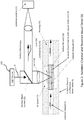
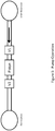
- the present invention takes the form of an apparatus generally indicated as 50 shown in Figure 1 that may include a microfluidic assay cartridge or device (1) which will contain at least one sample inlet well (2), as shown in Figure 1 (a) .
- Each sample inlet well (2) will feed, e.g. based at least partly on some control logic, into a respective microfluidic sub-unit (3) embedded within the microfluidic assay cartridge or device (1), as shown in Figures 1 and 1(b) .
- the microfluidic assay cartridge or device (1) is shown by way of example as having a plurality of sample inlet wells (2) in the form of 4 by 6 matrix, totally 24 sample inlet wells.
- the scope of the invention is not intended to be limited to the number of sample inlet wells (2), and is intended to include any number of sample inlet wells (2) ranging from 1 sample inlet well (2) to N sample inlet wells (2).
- the microfluidic assay cartridge or device (1) and/or microfluidic sub-unit (3) may be constructed and/or made from a material so as to be disposable or reusable, and the scope of the invention is not intended to be limited to the type or kind of material used to construct or make the microfluidic assay cartridge or device (1) and/or microfluidic sub-unit (3) either now known or later developed in the future.
- the microfluidic sub-unit (3) contains a series of microfluidic channels and micro-valves (4) that direct a sample, including a patient sample, such as serum, plasma, cerebrospinal fluid, urine, blood, etc., from the at least one sample inlet well (2) to separate and fluidicly-isolated channels (5) that contain one or more reaction vessels (19), which have been functionalized with a capture moiety or capture molecules such as antibodies, antigens, or oligomers, as shown in Figure 1(b) .
- a patient sample such as serum, plasma, cerebrospinal fluid, urine, blood, etc.
- each isolation channel (5) is shown having four reaction vessels (19) for a combine total of 16 reaction vessels is channels C1, C2, C3, C4, although the scope of the invention is not intended to be limited to any particular number of reaction vessels (19) in each isolation channel (5), consistent with that described herein.
- Assay reagents (7) including reagents R1, R2, R3, R4, such as labeled antibodies, will be introduced into the separate isolation channels (5) via the microfluidic channels (8) and micro-valves (4).
- the microfluidic channels (8) and micro-valves (9) are provided to introduce reagents such as an enzymatic substrate (10) for producing an emitted light signal and a wash solution (11) to remove any non-specifically bound proteins or antibodies.
- Figure 2 shows in further detail as generally indicated by (6) the isolation channel (5) and reaction vessel (19) embedded therein which has been designed such that it can tolerate a large confocal region or zone (18), and as a consequence may not require high resolution optics to avoid background fluorescence.
- the isolation channel and reaction vessel have been designed to enable very low cost manufacturing, and may include leveraging existing fiber optic and injection molded plastic technology. This low cost is achieved while at the same time providing very good optical qualities, increased sensitivity, decreased reaction time, large dynamic range, and low sample volume requirements.
- the biological reactions take place inside at least one hollow element (14) which has been functionalized with a capture moiety or molecules (15), so as to form the reaction vessel (19).
- the at least one hollow element (14) may be configured or fabricated by drawing glass tubing with an outer diameter and an inner diameter, and cutting or dicing it, e.g., with a dicing saw.
- the at least one hollow element (14) may also be configured or fabricated by etching out the core of commercially available high NA fused silica optical fibers or rods, which provide extremely high optical quality at a very low cost.
- the present invention is described by way of example with the at least one hollow element (14) being made of glass; however, the scope of the invention is intended to include making the at least one hollow element (14) from other types or kind of material either now known or later developed in the future, including other types or kinds of non-glass materials.
- the at least one hollow element (14) may be suspended in a housing (16) with a significant amount of air space (17) surrounding the outside diameter of the at least one hollow element (14). This air space (17) provides the large confocal zone (18) by providing an area that is free from any introduced background fluorescence.
- the at least one hollow element (14) may be installed with a press or friction fit into and received by walls of the housing (16), which is described in further detail below, that will direct the sample through the inside diameter of the at least one hollow element (14), and prevent the sample from entering the air space (17) surrounding the at least one hollow element (14).
- the at least one hollow element (14) may be configured or designed with a cavity or chamber having a very small inside diameter (e.g., approximately 10 ⁇ m inner diameter (ID)) and a length-to-I.D. aspect ratio of, e.g., approximately 20:1 (approximately 200 ⁇ m L). This configuration provides the reaction vessel (19) with a very high surface area-to-volume ratio, which in-turn drives fast reaction kinetics.
- the isolation channel and reaction vessel detail is understood to take the form of at least one hollow element (14) that is functionalized with the capture moiety or molecules (15), and is arranged in and coupled to the housing (16) in an isolation channel (5) as shown.
- light L in from a light source (20) can be passed through a dichroic beam splitter (22), a lens (24) and the air space (17) to the large confocal region or zone (18); and light L out can be passed back through the air space (17), the lens (24), the dichroic beam splitter (22), a lens (26) to the detector (13).
- a plurality of hollow elements (14) of decreasing inside diameters can be functionalized and placed in-line to address varying analyte densities, prevent oversaturation, and extend the dynamic range of the systems analysis capabilities.
- a plurality of hollow elements of the same diameter that have been functionalized with different loading densities of the capture moiety or molecules can be placed in-line to address varying analyte densities, prevent over saturation, and extend the dynamic range. It is also envisioned that combinations of the above configuration can be employed to achieve optimized results.
- each of the at least one sample inlet well (2) of the disposable microfluidic assay cartridge or device (1) corresponds to a respective microfluidic sub-unit (3) embedded within the disposable microfluidic assay cartridge (1).
- the scope of the invention is also intended to include embodiments in which multiple sample inlet wells (2) of the disposable microfluidic assay cartridge or device (1) are configured to correspond to a respective microfluidic sub-unit (3) via, e.g., a manifold device (not shown).
- each assay reagent R1, R2, R3, R4 may correspond to, feed into and be assigned to a respective isolation channel C1, C2, C3, C4.
- the scope of the invention is also intended to include embodiments in which each assay reagent R1, R2, R3, R4 feeds into multiple channels C1, C2, C3, C4.
- each of the microfluidic sub-units (3) embedded within the disposable microfluidic assay cartridge (1) has a respective detection system (13).
- the scope of the invention is also intended to include embodiments in which multiple microfluidic sub-unit (3) are configured to correspond to a respective detection system (13).
- a first column or group of four microfluidic sub-unit (3) may correspond to a first detection system (13);
- a second column or group of four microfluidic sub-unit (3) may correspond to a second detection system (13); ...;
- a sixth column or group of four microfluidic sub-unit (3) may correspond to a sixth detection system (13).
- a first row or group of six microfluidic sub-unit (3) may correspond to a first detection system (13); a second row or group of six microfluidic sub-unit (3) may correspond to a second detection system (13); ...; and a fourth row or group of six microfluidic sub-unit (3) may correspond to a fourth detection system (13).
- the scope of the invention is also intended to include embodiments in which N microfluidic sub-unit (3), where N, e.g., equals 24 corresponding to that shown in Figure 1 , are configured to correspond to a single detection system (13).
- the scope of the invention is also intended to include embodiments in which the detection system (13) is on-board and forms part of microfluidic sub-unit (3), as well as embodiments where the detection system (13) is not on-board but forms part of another device, apparatus or equipment either now known or later developed in the future.
- the apparatus may also include a controller (140) for implementing the functionality associated with the assay performed by the microfluidic sub-unit (3) embedded within the disposable microfluidic assay cartridge or device (1).
- the controller (140) may be configured to execute a computer program code and to provide the signaling along signal paths, e.g., S 0 , S 1 , S 2 , S 3 , S 4 , S 5 , S 6 , ..., S 10 to each microfluidic channel (8) and/or micro-valves (4, 9) in order to perform the assay.
- the controller (140) may be configured to execute the computer program code and to exchange signaling along signal path S 7 with the detection system (13), including receiving a detection system signal containing information about the reactions taking place in the reaction vessels (19) being interrogated by the detection system (13).
- the controller (140) may also be configured to receive an input signal(s) along signal path S in , and to provide an output signal(s) along signal path S out .
- the output signal along signal path S out may contain either the raw detection system signal containing information about the reactions taking place in the reaction vessels (19) being interrogated by the detection system (13), or a processed detection system signal containing information about the reactions taking place in the reaction vessels (19) being interrogated by the detection system (13).
- the input signal along signal path S in may contain information to control or modify the functionality of the controller (140), including a signal requesting the provisioning of the output signal along signal path S out .
- the scope of the invention is not intended to be limited to the type or kind of information being provided to or received by the controller (140) via the input signal along signal path S in or the type or kind of information being provided from the controller (140) via the output signal along signal path S out either now known or later developed in the future.
- the controller (140) may be implemented using hardware, software, firmware, or a combination thereof.
- the controller (140) would include one or more microprocessor-based architectures having a processor or microprocessor, memory such as a random access memory (RAM) and/or a read only memory (ROM), input/output devices and control, data and address buses connecting the same.
- RAM random access memory
- ROM read only memory
- a person skilled in the art would be able to program such a microcontroller or microprocessor-based implementation with the computer program code to perform the functionality described herein without undue experimentation.
- the scope of the invention is not intended to be limited to any particular microprocessor-based architecture implementation using technology either now known or later developed in the future.
- controller (140) either is on-board and forms part of the apparatus (50), or is not on-board but forms part of another apparatus, device, system or equipment that cooperates with the apparatus (50) in relation to implementing the assay process with the microfluidic technology disclosed herein.
- the microfluidic sub-unit (3) is shown, by way of example, with micro-valves (4, 9) arranged in relation to the substrate (10), the wash (11) and the assay reagents (7) to control the introduction of the assay reagents to the isolation channels (5) in response to the signalling along signalling paths S 0 , S 1 , S 2 , S 3 , S 4 , S 5 , S 6 , ..., S 10 using steps 3-8 described below and set forth in the flowchart shown in Figure 1 (c) .
- Embodiments are also envisioned in which the micro-valves (4) provide information back to the controller (140) via corresponding signalling along signalling paths S 0 , S 1 , S 2 , S 3 , S 4 , S 5 , S 6 , ..., S 10 , for controlling the introduction of the assay reagents (7), the substrate (10) and the wash (11).
- Embodiments are also envisioned in which other micro-valves are arranged at other points in relation to each microfluidic channel (8), e.g.
- micro-valves (4a) in Figure 1(b) arranged in relation to the interface between each microfluidic channel (8) and the at least one sample inlet well (2) for controlling the provisioning of the sample into the microfluidic channel (8) with signalling along signal path S 0 .
- other micro-valves are arranged in relation to the isolation channels (5), including at either or both ends, so as to control the passage of the solution, reagents or buffer through the isolation channels (5).
- the scope of the invention is not intended to be limited to the number, position, or arrangements of the micro-valves, like (4) or (4a) or (9).
- micro-valves (4, 4a, 9), isolation channels (5), detection system (13), along with other components or devices shown and described herein in relation to Figure 1 are either known in the art, or can be implemented to perform the desired functionality without undue experimentation by one skilled in the art; and the scope of the invention is not intended to be limited to any particular type or kind thereof either now known or later developed in the future.
- one skilled in the art could implement the apparatus 50 shown in Figure 1 , including the microfluidic assay cartridge (1) shown in Figure 1(a) and the microfluidic sub-unit (3) embedded therein shown in Figure 1(b) , to perform the desired functionality without undue experimentation.
- the present invention is described by way of using micro-valves configured to control the flow of one or more of the sample, the assay reagents (7), the substrate (10) and the wash (13) into the at least one separate and fluidicly-isolated isolation channels (5).
- the scope of the invention is intended to include using other types or kind of techniques either now known or later developed in the future to control the flow of one or more of the sample, the assay reagents (7), the substrate (10) and the wash (13) into the at least one separate and fluidicly-isolated isolation channels (5), e.g., such as by using a configuration to provide positive pressure to push and cause the flow of one or more of the sample, the assay reagents (7), the substrate (10) and the wash (13) into the at least one separate and fluidicly-isolated isolation channels (5), or such as by using a configuration to provide negative pressure (e.g.
- a vacuum to pull (or draw) and cause the flow of one or more of the sample, the assay reagents (7), the substrate (10) and the wash (13) into the at least one separate and fluidicly-isolated isolation channels (5), or such as by using some combination of pushing and/or pulling to cause the flow of one or more of the sample, the assay reagents (7), the substrate (10) and the wash (13) into the at least one separate and fluidicly-isolated isolation channels (5).
- the configuration to provide positive pressure may be configured on the upper end (as shown in Figure 1(b) ) of the at least one separate and fluidicly-isolated isolation channels (5) in relation to the assay reagents (7) and channels C1, C2, C3, C4, while the configuration to provide negative pressure may be configured on the lower end (as shown in Figure 1 (b) ) of the at least one separate and fluidicly-isolated isolation channel (5) in relation to the waste (12) and channels C1, C2, C3, C4.
- the process of conducting an immunoassay in a cartridge according to the present invention using a sandwich enzyme-linked immunosorbent assay may entail some combination of the following:
- Step 2 The reaction vessel (19) once placed into the isolation channel (5) is then ready to receive the patient sample (serum, plasma, cerebrospinal fluid, urine, blood, etc).
- patient sample serum, plasma, cerebrospinal fluid, urine, blood, etc.
- Step 3 A precise volume of the patient sample is then introduced by flowing the material into the reaction vessel (19), either, e.g., by positive or negative pressure, during which time the target analyte of interest is retained by virtue of specific binding to the capture antibody coated onto the interior surface of the reaction vessel (19).
- Step 4 The reaction vessel (19) is then rinsed with a buffer to wash away the unbound protein.
- Step 5 The second antibody, referred to as a detection antibody since it is coupled to a fluorescent tag capable of emitting a light signal, is then is flowed into the reaction vessel (19) whereupon it binds to the target analyte retained on the interior surface via the capture antibody.
- Step 5a An alternative embodiment of this process may be to use a second antibody without a fluorescent conjugate, and then to add the fluorescent conjugate in a subsequent step. Note that this may also include an additional rinse step prior to adding the fluorescent conjugate.
- Step 6 The reaction vessel (19) is then rinsed again with a buffer to remove unbound protein, and the excess fluorescent tag.
- Step 7 The amount of the target analyte captured is then quantified by the amount of fluorescent light emitted by the detection antibody as a result of irradiating the fluorescent chemical tag with the appropriate excitation wavelength onto the reaction vessel (19).
- Step 8 The amount of analyte within the reaction vessel (19) is proportional to the amount of light emitted by the detection antibody fluorescent tag, and hence is directly proportional to the amount of analyte within the patient sample.
- the controller (140) shown in Figure 1(b) may be implemented and configured to provide the signalling to perform the biological assay using, e.g., steps 3-8 set forth above.
- the scope of the invention is described by way of example using the sandwich ELISA biological assay technique.
- the scope of the invention is not intended to be limited to using the sandwich ELISA biological assay technique, e.g., embodiments are also envisioned using other types or kind of biological assay techniques either now known or later developed in the future, including an "indirect" ELISA, a competitive ELISA, a reverse ELISA, as well as other non-ELISA techniques.
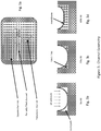
- Figure 3 shows channel geometry of an isolation channel (5) that may form part of the microfluidic sub-unit (3) shown in Figure 1 (b) according to some embodiments of the present invention.
- Figure 3a shows examples of a square channel, a partially filled channel and a pneumatic channel.
- the channel may be partially filled with Polydimethylsiloxane (PDMS) fillet to form a conformal surface for a membrane seal, configured to engage an outer surface of the hollow element (14). See Figure 3c .
- PDMS Polydimethylsiloxane
- partially filling a channel with PDMS could be used to engage the outer surface of the hollow element so as to reduce the free volume around the cylinder.
- PDMS is a material that belongs to a group of polymeric organosilicon compounds that are commonly referred to as silicones. PDMS material doesn't fluoresce which is important in processing the light signal received back from the reaction vessel (19).
- Figures 3e ( 1 ) and 3e(2) show the hollow element (14) fit within walls W1, W2 of the housing (16) that forms part of the isolation channel (5). See Figure 1b and Figure 3b .
- the hollow element (14) is retained in channel by friction fit with walls W1, W2. Free space exists between outside of the hollow element (14) and channel walls W1, W2.
- Figures 3f ( 1 ) and 3(f)2 show the hollow element (14) fit within walls W1, W2 of the housing (16) that forms part of the isolation channel (5) with fill. See Figure 1 b and Figures 3b and 3c .
- the hollow element (14) is retained in channel (5) by a fill material that may take the form of an epoxy-like material, silicone rubber, etc., placed in channel floor prior to insertion of the hollow element fit (14).
- the isolation channel (5) may be completely filled around the hollow element fit (14) to completely block flow around particle.
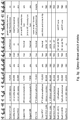
- an epoxy down select matrix shows rows of epoxy in relation to columns of parameters, including indication of type, viscosity, dispensable, background fluorescence, cure method, comment and acceptable.
- the PDMS material includes the Sylgard 184, Sylgard 186 and the Nusil materials listed.
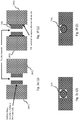
- Figure 4 shows, by way of example, one prototype of a pneumatically actuated pump having valves, a piston, a fluidic channel and pneumatic lines according to some embodiments of the present invention.
- the piston displacement for this prototype is about 200 nl (nanoliters), which may be far more than what is likely to be required.
- Figure 5 shows an example of pump operation in relation to valves and a piston arranged between an inlet reservoir and a destination according to some embodiments of the present invention.
- the pump operation includes pumping that is accomplished by combining 2 pneumatically actuated valves V1, V2 with at least one pneumatically actuated piston located between the two valves V1, V2.
- the purpose of the piston is simply to displace fluid, either by pulling it in from a reservoir or pushing it in the direction of the flow.
- the valves V1, V2, which buttress the piston, ensure unidirectional flow.
- Full operation is accomplished by actuating the 3 components in a particular sequence.
- a valve sequence may entail the following: close the valve V1, compress the Piston, close the valve V2, open the valve V1, decompress the piston, close valve V1, open the valve V2 and compress the Piston.
- the flow can be generated by combining any set of 2 valves and a piston.
- valves can double used as simple open and close valves or they can be incorporated into a pump as described here.
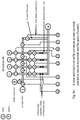
- Figure 6a(1) , 6b , 6c and 6d show various 4-plex architectures for performing an assay according to some embodiments of the present invention.
- Figure 6a(1) shows a 4-plex architecture with independent pump control and individual waste reservoirs
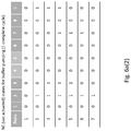
- Figure 6a(2) shows the NC (vac actuated) states for buffer pumping (1 complete cycle) for the 4-plex architecture shown in Figure 6a(1) , according to some embodiments of the present invention.
- the fluidic network shown in Figure 6a(1) there are a number of fluidic channels C1, C2, C3, C4 with pneumatically actuated valves V located at various locations along the channels. The valves V connected to one another are actuated simultaneously.
- Valve set 3 is pistons and valve set 4 is the outlet valves and these are used for all of the pumping operations regardless of the fluid source.
- the particular valve used in combination to provide pumping may be 1, 8 or 7 respectively.
- Figure 6a(2) shown the state diagram for one complete sequence required to pump buffer from the source through the main channels and out the their respective waste reservoirs.
- Figure 6b shows a 4-plex architecture with independent pump control similar to the 4-plex in Figure 6a(1) , but with a common waste reservoir W feeding from the isolation channels (5).
- Figure 6c shows an example of a 4-plex architecture with a common pump control and a common waste reservoir similar to the 4-plex in Figure 6b , but with a by-pass channel feeding from the microchannel to the common waste reservoir.
- Figure 6d shows an example of a 4-plex architecture with a common pump control, a common waste reservoir and a by-pass channel similar to the 4-plex in Figure 6c , but with an antibody rehydration channel.
- the present invention may also take the form of a method for performing the assay process using a new and unique separation technique consistent with that set forth above.
- the method may be implemented by providing the means set forth above for automatically separating components where negative cross reactions occur, and by employing the disposable microfluidic assay cartridge that will automate some of the manual steps typically associated with these types of tests.
- the separation technique set forth herein for performing the assay process will eliminate the need to design around cross reactivity.
- the method for performing an assay may be implemented using the microfluidic technology in Figure 1 as follows:
- the method may also comprise responding to the signaling containing information about performing the assay with the microfluidic channels (8) and micro-valves (4, 9) and introducing into the reaction vessel (19) the following:
- the method for performing an assay may also be implemented using the microfluidic technology in Figure 2 .
- the method for performing a biological assay may also be implemented using the steps set forth above, including those set forth in relation to Figure 1(c) .
- a singular and multiplexed biological assay may be performed by using at least one functionalized hollow glass cylinder, tube or particle (14) in different isolation channel (5), by using multiple functionalized hollow glass cylinders, tubes or particles (14) in the same isolation channel (5), or by using multiple functionalized hollow glass cylinders, tubes or particles (14) in multiple isolation channels (5).
- a multiplexed biological assay may be performed by using multiple reaction vessels, each with different concentrations of capture molecules, all located in a single isolation channel.
- a first isolation channel C1 may include three reaction vessels, one with a low concentration of capture molecules immobilized on it, a second reaction vessel with a higher concentration of capture molecules immobilized on it, and third reaction vessel with an even higher concentration of capture molecules immobilized on it.
- a second isolation channel could include reaction vessels with the same range of capture concentrations or a completely different range of capture concentrations or a set of reaction vessels with all of the same reaction concentration.
- a multiplexed biological assay may be performed by using multiple reaction vessels, each with different inner diameters, all located in the same isolation channel.
- a first isolation channel C1 may include three reaction vessels, one with a small inside diameter and surface area, a second reaction vessel with a larger inside diameter and surface area, and third reaction vessel with an even larger inside diameter and surface area, so as to introduce different reaction kinetics.
- a second isolation channel C2 could contain the same set of reaction vessels with the same range of inner diameters or contain a completely different set of reaction vessels with a different range of inner diameters or with all of the same diameters.
- a multiplexed biological assay may be performed by using positive and negative controls.
- a first isolation channel C1 may include using a positive control, and a negative control while a second isolation channel C2 may also include using a positive and negative control that shouldn't react.
- biological assays with +/- controls may include using functionalized hollow glass cylinders, tubes or particles (14) having different antibodies, where the + control spikes and the - control does not react, but can be used, e.g., to gain information about background fluorescents.
- a multiplexed biological assay may be performed by using different channels having different numbers of analytes, e.g., a first isolation channel C1 may include a first number of analytes (e.g. 1), a second isolation channel C2 may include a second number of analytes (e.g. 3), and a third isolation channel C3 may include a third number of analytes, ..., an Nth isolation channel has an Nth number of analytes.
- a first isolation channel C1 may include a first number of analytes (e.g. 1)
- a second isolation channel C2 may include a second number of analytes (e.g. 3)
- a third isolation channel C3 may include a third number of analytes, ...
- an Nth isolation channel has an Nth number of analytes.
- a multiplexed biological assay may be performed by using different isolation channels having different biological assays.
- a first isolation channel C1 may include a first biological assay A
- a second isolation channel C2 may include a second biological assay B
- a third isolation channel C3 may include a third biological assay A+B, so that channels can be looked at individually and together, which the channel B biological assay and the channel A + B biological assay can be used to provide further information about the channel A biological assay.
- the present invention affords the possibility of a broad range of hybrid (or conventional) multiplex concepts, including (1) multiple reaction vessels in the same isolation channel, functionalized with different loading densities to extend the dynamic range; (2) multiple reaction vessels with different inner diameters, in the same isolation channel, to introduce different reaction kinetics; (3) multiple reaction vessels having positive and negative controlled reaction vessels in the same isolation channel; (4) multiple reaction vessels with different capture moieties in the same isolation channel, for the purpose of providing a multiplexed (conventional) reaction; and (5) multiple reaction vessels to conduct monoplex and multiplex reactions so that the results may be compared.
- the scope of the invention is also intended to include other types or kinds of assays, including a chemical assay or a biological assay, either now known or later developed in the future.
- a microfluidic chip consisting of fluidic channels, including isolation with three embedded reaction vessels, pneumatic control lines and inlet/outlet ports, where the three reaction vessels are embedded in isolation channel.
- Figure 7c ( 1 ) and 7c(2) show the real-time signal evolution due to binding of secondary Ab (IL6) to previously captured antigen inside 3 embedded reaction vessels, and fluorescence images of three embedded reaction vessels taken 15 minutes after flowing detection Ab through the isolation channel and the embedded reaction vessel.
- IL6 secondary Ab
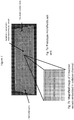
- Figure 7d shows dose response curves for an IL6 sandwich assay performed on the reaction vessels in batch mode.
- Each data point represents a subset of reaction vessels, take from the same original batch of reaction vessels, but mixed with different IL6 antigen concentrations ranging from 0 pg/ml to 100,000 pg/ml.
- IL6 antigen concentrations ranging from 0 pg/ml to 100,000 pg/ml.
- This batch mode process would be used to both characterize a particular set of reaction vessels and verify the quality of the batch on the very inexpensive component.
- Figure 8 shows the hollow element may be configured as a honeycomb with multiple axial cavities or chambers that provides, when functionalized, a highly increased surface to volume ratio when compared to a reaction vessel having a single axial cavity or chamber affording the benefit of higher reaction kinetics and that also provides increased signal interrogation for the same effective volume.
- microfluidics is generally understood to mean or deal with the behavior, precise control and manipulation of fluids that are geometrically constrained to a small, typically sub-millimeter, scale.
- the microfluidic technology described herein is intended to include technology dimensioned in a range of about 20 micron to about 1000 microns, although the scope of the invention is not intended to be limited to any particular range.
Landscapes
- Health & Medical Sciences (AREA)
- Chemical & Material Sciences (AREA)
- Immunology (AREA)
- Life Sciences & Earth Sciences (AREA)
- General Health & Medical Sciences (AREA)
- Analytical Chemistry (AREA)
- Hematology (AREA)
- Engineering & Computer Science (AREA)
- Dispersion Chemistry (AREA)
- Biomedical Technology (AREA)
- Urology & Nephrology (AREA)
- Molecular Biology (AREA)
- Clinical Laboratory Science (AREA)
- Pathology (AREA)
- Physics & Mathematics (AREA)
- Chemical Kinetics & Catalysis (AREA)
- Biochemistry (AREA)
- General Physics & Mathematics (AREA)
- Cell Biology (AREA)
- Medicinal Chemistry (AREA)
- Food Science & Technology (AREA)
- Microbiology (AREA)
- Biotechnology (AREA)
- Automatic Analysis And Handling Materials Therefor (AREA)
- Apparatus Associated With Microorganisms And Enzymes (AREA)
Applications Claiming Priority (2)
| Application Number | Priority Date | Filing Date | Title |
|---|---|---|---|
| US26357209P | 2009-11-23 | 2009-11-23 | |
| PCT/US2010/057860 WO2011063408A1 (en) | 2009-11-23 | 2010-11-23 | Method and apparatus for performing assays |
Publications (3)
| Publication Number | Publication Date |
|---|---|
| EP2504701A1 EP2504701A1 (en) | 2012-10-03 |
| EP2504701A4 EP2504701A4 (en) | 2013-08-21 |
| EP2504701B1 true EP2504701B1 (en) | 2017-09-13 |
Family
ID=44060083
Family Applications (1)
| Application Number | Title | Priority Date | Filing Date |
|---|---|---|---|
| EP10832371.8A Active EP2504701B1 (en) | 2009-11-23 | 2010-11-23 | Method and apparatus for performing assays |
Country Status (7)
| Country | Link |
|---|---|
| US (1) | US9229001B2 (enExample) |
| EP (1) | EP2504701B1 (enExample) |
| JP (2) | JP5701894B2 (enExample) |
| CN (1) | CN102713621B (enExample) |
| CA (1) | CA2781556C (enExample) |
| ES (1) | ES2649559T3 (enExample) |
| WO (1) | WO2011063408A1 (enExample) |
Families Citing this family (26)
| Publication number | Priority date | Publication date | Assignee | Title |
|---|---|---|---|---|
| US20110143378A1 (en) * | 2009-11-12 | 2011-06-16 | CyVek LLC. | Microfluidic method and apparatus for high performance biological assays |
| WO2013142847A1 (en) * | 2012-03-22 | 2013-09-26 | Cyvek, Inc | Pdms membrane-confined nucleic acid and antibody/antigen-functionalized microlength tube capture elements, and systems employing them |
| US9651568B2 (en) | 2009-11-23 | 2017-05-16 | Cyvek, Inc. | Methods and systems for epi-fluorescent monitoring and scanning for microfluidic assays |
| WO2013134741A2 (en) * | 2012-03-08 | 2013-09-12 | Cyvek, Inc. | Methods and systems for manufacture of microarray assay systems, conducting microfluidic assays, and monitoring and scanning to obtain microfluidic assay results |
| US9855735B2 (en) | 2009-11-23 | 2018-01-02 | Cyvek, Inc. | Portable microfluidic assay devices and methods of manufacture and use |
| US10065403B2 (en) | 2009-11-23 | 2018-09-04 | Cyvek, Inc. | Microfluidic assay assemblies and methods of manufacture |
| US9500645B2 (en) | 2009-11-23 | 2016-11-22 | Cyvek, Inc. | Micro-tube particles for microfluidic assays and methods of manufacture |
| US9759718B2 (en) | 2009-11-23 | 2017-09-12 | Cyvek, Inc. | PDMS membrane-confined nucleic acid and antibody/antigen-functionalized microlength tube capture elements, and systems employing them, and methods of their use |
| US9700889B2 (en) | 2009-11-23 | 2017-07-11 | Cyvek, Inc. | Methods and systems for manufacture of microarray assay systems, conducting microfluidic assays, and monitoring and scanning to obtain microfluidic assay results |
| CN103649759B (zh) | 2011-03-22 | 2016-08-31 | 西维克公司 | 微流体装置以及制造方法和用途 |
| DE102012205171B3 (de) * | 2012-03-29 | 2013-09-12 | Fraunhofer-Gesellschaft zur Förderung der angewandten Forschung e.V. | Integriertes Einweg-Chipkartuschensystem für mobile Multiparameteranalysen chemischer und/oder biologischer Substanzen |
| US9458488B2 (en) * | 2013-03-15 | 2016-10-04 | Nanomix, Inc. | Point of care sensor systems |
| WO2014150853A1 (en) * | 2013-03-15 | 2014-09-25 | Inanovate, Inc. | Analyte measurement using longitudinal assay |
| US20170113221A1 (en) * | 2014-06-11 | 2017-04-27 | Micronics, Inc. | Microfluidic cartridges and apparatus with integrated assay controls for analysis of nucleic acids |
| CN104568537A (zh) * | 2014-11-05 | 2015-04-29 | 华文蔚 | 一种处理生物微流体样本的方法 |
| EP3288681A1 (en) * | 2015-04-30 | 2018-03-07 | Orphidia Limited | Microfluidic valves and devices |
| US10228367B2 (en) | 2015-12-01 | 2019-03-12 | ProteinSimple | Segmented multi-use automated assay cartridge |
| US9933445B1 (en) | 2016-05-16 | 2018-04-03 | Hound Labs, Inc. | System and method for target substance identification |
| CA3035286A1 (en) * | 2016-10-07 | 2018-04-12 | Boehringer Ingelheim Vetmedica Gmbh | Method and analysis system for testing a sample |
| US20200245898A1 (en) * | 2019-01-31 | 2020-08-06 | Hound Labs, Inc. | Single-use Microfluidic Cartridge for Detection of Target Chemical Presence in Human Breath |
| BR112021017166A2 (pt) * | 2019-03-01 | 2021-11-09 | Vidya Holdings Ltd | Cartucho de ensaio para detectar um componente alvo em um fluido, e, método para fabricar um arranjo de cartuchos de ensaio |
| US11977086B2 (en) | 2019-03-21 | 2024-05-07 | Hound Labs, Inc. | Biomarker detection from breath samples |
| US11933731B1 (en) | 2020-05-13 | 2024-03-19 | Hound Labs, Inc. | Systems and methods using Surface-Enhanced Raman Spectroscopy for detecting tetrahydrocannabinol |
| US12392769B1 (en) | 2021-01-12 | 2025-08-19 | Hound Labs, Inc. | Ambient contamination in breath analyte detection and measurement |
| CN114345430B (zh) * | 2022-01-14 | 2022-10-28 | 北京工商大学 | 一种通过纸基微流控芯片同时检测多种抗生素残留的便携式装置 |
| US20250128256A1 (en) * | 2022-01-25 | 2025-04-24 | President And Fellows Of Harvard College | Microfluidic devices with autonomous directional valves |
Family Cites Families (269)
| Publication number | Priority date | Publication date | Assignee | Title |
|---|---|---|---|---|
| US5622871A (en) | 1987-04-27 | 1997-04-22 | Unilever Patent Holdings B.V. | Capillary immunoassay and device therefor comprising mobilizable particulate labelled reagents |
| SE343949B (enExample) | 1966-06-02 | 1972-03-20 | Pharmacia Ab | |
| US3867517A (en) | 1971-12-21 | 1975-02-18 | Abbott Lab | Direct radioimmunoassay for antigens and their antibodies |
| US3939350A (en) | 1974-04-29 | 1976-02-17 | Board Of Trustees Of The Leland Stanford Junior University | Fluorescent immunoassay employing total reflection for activation |
| US3876376A (en) | 1974-05-09 | 1975-04-08 | American Cyanamid Co | Linear determination of hemolytic complement activity in undiluted serum |
| US4222744A (en) | 1978-09-27 | 1980-09-16 | Becton Dickinson & Company | Assay for ligands |
| US4254096A (en) | 1979-10-04 | 1981-03-03 | Bio-Rad Laboratories, Inc. | Reagent combination for solid phase immunofluorescent assay |
| US4517288A (en) | 1981-01-23 | 1985-05-14 | American Hospital Supply Corp. | Solid phase system for ligand assay |
| US4425438A (en) | 1981-03-13 | 1984-01-10 | Bauman David S | Assay method and device |
| US4368047A (en) | 1981-04-27 | 1983-01-11 | University Of Utah Research Foundation | Process for conducting fluorescence immunoassays without added labels and employing attenuated internal reflection |
| NZ201901A (en) | 1981-09-25 | 1986-11-12 | Commw Serum Lab Commission | An apparatus suitable for performing automated heterogeneous immunoassays in a plurality of samples |
| DE3226407C2 (de) | 1982-07-15 | 1985-05-15 | Volker Dr. 6900 Heidelberg Daniel | Mikro-Analyse-Kapillar-System |
| US4447546A (en) | 1982-08-23 | 1984-05-08 | Myron J. Block | Fluorescent immunoassay employing optical fiber in capillary tube |
| JPH0627742B2 (ja) | 1982-12-21 | 1994-04-13 | コムテツク リサ−チ ユニツト リミテツド | 検定方法及びそのための装置 |
| EP0149168B1 (en) | 1983-12-19 | 1991-04-24 | Daiichi Pure Chemicals Co. Ltd. | Immunoassay |
| US4581624A (en) | 1984-03-01 | 1986-04-08 | Allied Corporation | Microminiature semiconductor valve |
| JPH06105261B2 (ja) * | 1984-03-05 | 1994-12-21 | 株式会社東芝 | 濃度勾配測定装置 |
| US5004923A (en) | 1985-08-05 | 1991-04-02 | Biotrack, Inc. | Capillary flow device |
| US5164598A (en) | 1985-08-05 | 1992-11-17 | Biotrack | Capillary flow device |
| US4716121A (en) | 1985-09-09 | 1987-12-29 | Ord, Inc. | Fluorescent assays, including immunoassays, with feature of flowing sample |
| US4844869A (en) | 1985-09-09 | 1989-07-04 | Ord, Inc. | Immunoassay apparatus |
| US5500350A (en) | 1985-10-30 | 1996-03-19 | Celltech Limited | Binding assay device |
| US4820490A (en) | 1986-09-11 | 1989-04-11 | Miles Inc. | Device and method for chemical analysis of fluids with a reagent coated light source |
| US4717545A (en) | 1986-09-11 | 1988-01-05 | Miles Inc. | Device and method for chemical analysis of fluids with a reagent coated light source |
| US4797259A (en) | 1986-12-15 | 1989-01-10 | Pall Corporation | Well-type diagnostic plate device |
| US4923819A (en) | 1987-03-27 | 1990-05-08 | Chimerix Corporation | Time-resolved fluorescence immunoassay |
| US4857453A (en) | 1987-04-07 | 1989-08-15 | Syntex (U.S.A.) Inc. | Immunoassay device |
| DE3878820T2 (de) | 1987-04-29 | 1993-07-22 | Celltech Ltd | Vorrichtung fuer bindungstest. |
| US5009998A (en) | 1987-06-26 | 1991-04-23 | E. I. Du Pont De Nemours And Company | Method for performing heterogeneous immunoassay |
| US5041181A (en) | 1987-10-06 | 1991-08-20 | Integrated Fluidics Company | Method of bonding plastics |
| US4908116A (en) | 1989-06-01 | 1990-03-13 | The Board Of Trustees At The Leland Stanford Junior University | Capillary electrophoretic device employing structure permitting electrical contact through ionic movement |
| US5302349A (en) | 1989-06-13 | 1994-04-12 | Diatron Corporation | Transient-state luminescence assay apparatus |
| US6008057A (en) | 1989-08-25 | 1999-12-28 | Roche Diagnostics Corporation | Immunoassay system |
| US5183740A (en) | 1990-02-23 | 1993-02-02 | The United States Of America As Represented By The Secretary Of The Navy | Flow immunosensor method and apparatus |
| SE470347B (sv) | 1990-05-10 | 1994-01-31 | Pharmacia Lkb Biotech | Mikrostruktur för vätskeflödessystem och förfarande för tillverkning av ett sådant system |
| JPH06501099A (ja) | 1990-09-11 | 1994-01-27 | ヴォアヒーズ・テクノロジース・インコーポレーテッド | 被覆された毛管 |
| JP2523227Y2 (ja) | 1991-07-30 | 1997-01-22 | 株式会社堀場製作所 | 異物検査装置 |
| US5296375A (en) | 1992-05-01 | 1994-03-22 | Trustees Of The University Of Pennsylvania | Mesoscale sperm handling devices |
| US5637469A (en) | 1992-05-01 | 1997-06-10 | Trustees Of The University Of Pennsylvania | Methods and apparatus for the detection of an analyte utilizing mesoscale flow systems |
| US5304487A (en) | 1992-05-01 | 1994-04-19 | Trustees Of The University Of Pennsylvania | Fluid handling in mesoscale analytical devices |
| US5885527A (en) * | 1992-05-21 | 1999-03-23 | Biosite Diagnostics, Inc. | Diagnostic devices and apparatus for the controlled movement of reagents without membrances |
| JPH06108242A (ja) | 1992-09-25 | 1994-04-19 | Minolta Camera Co Ltd | 薄膜電極および薄膜製造装置 |
| US5508200A (en) | 1992-10-19 | 1996-04-16 | Tiffany; Thomas | Method and apparatus for conducting multiple chemical assays |
| US5534328A (en) | 1993-12-02 | 1996-07-09 | E. I. Du Pont De Nemours And Company | Integrated chemical processing apparatus and processes for the preparation thereof |
| US5493802A (en) | 1993-05-26 | 1996-02-27 | Simson; Anton K. | Scroll displaying device |
| US5837546A (en) | 1993-08-24 | 1998-11-17 | Metrika, Inc. | Electronic assay device and method |
| ATE224053T1 (de) | 1993-11-12 | 2002-09-15 | Inverness Medical Switzerland | Vorrichtung zum ablesen von teststreifen |
| US5976896A (en) | 1994-06-06 | 1999-11-02 | Idexx Laboratories, Inc. | Immunoassays in capillary tubes |
| US5624850A (en) | 1994-06-06 | 1997-04-29 | Idetek, Inc. | Immunoassays in capillaries |
| US5593290A (en) | 1994-12-22 | 1997-01-14 | Eastman Kodak Company | Micro dispensing positive displacement pump |
| US5856174A (en) | 1995-06-29 | 1999-01-05 | Affymetrix, Inc. | Integrated nucleic acid diagnostic device |
| US6068751A (en) | 1995-12-18 | 2000-05-30 | Neukermans; Armand P. | Microfluidic valve and integrated microfluidic system |
| US6541213B1 (en) | 1996-03-29 | 2003-04-01 | University Of Washington | Microscale diffusion immunoassay |
| US5788814A (en) | 1996-04-09 | 1998-08-04 | David Sarnoff Research Center | Chucks and methods for positioning multiple objects on a substrate |
| US5942443A (en) | 1996-06-28 | 1999-08-24 | Caliper Technologies Corporation | High throughput screening assay systems in microscale fluidic devices |
| US5885470A (en) | 1997-04-14 | 1999-03-23 | Caliper Technologies Corporation | Controlled fluid transport in microfabricated polymeric substrates |
| JPH09288089A (ja) | 1996-04-23 | 1997-11-04 | Hitachi Ltd | 毛細管電気泳動装置 |
| CA2253710A1 (en) | 1996-04-25 | 1997-10-30 | Spectrametrix Inc. | Analyte assay using particulate labels |
| US7341727B1 (en) | 1996-05-03 | 2008-03-11 | Emergent Product Development Gaithersburg Inc. | M. catarrhalis outer membrane protein-106 polypeptide, methods of eliciting an immune response comprising same |
| NZ333346A (en) | 1996-06-28 | 2000-03-27 | Caliper Techn Corp | High-throughput screening assay systems in microscale fluidic devices |
| US20030054376A1 (en) | 1997-07-07 | 2003-03-20 | Mullis Kary Banks | Dual bead assays using cleavable spacers and/or ligation to improve specificity and sensitivity including related methods and apparatus |
| DE19635646C1 (de) | 1996-09-03 | 1997-12-04 | Bruker Franzen Analytik Gmbh | Korrektur der Massenbestimmung mit MALDI-Flugzeitmassenspektrometern |
| EP0990142A4 (en) | 1996-12-31 | 2000-09-27 | Genometrix Genomics Inc | MULTIPLEXED MOLECULAR ANALYSIS METHOD AND DEVICE |
| US6507989B1 (en) | 1997-03-13 | 2003-01-21 | President And Fellows Of Harvard College | Self-assembly of mesoscale objects |
| US6391622B1 (en) | 1997-04-04 | 2002-05-21 | Caliper Technologies Corp. | Closed-loop biochemical analyzers |
| KR100351531B1 (ko) | 1997-04-25 | 2002-09-11 | 캘리퍼 테크놀로지스 코포레이션 | 기하형상이 개선된 채널을 채용하는 미소 유체 장치 |
| US6020209A (en) | 1997-04-28 | 2000-02-01 | The United States Of America As Represented By The Secretary Of The Navy | Microcapillary-based flow-through immunosensor and displacement immunoassay using the same |
| US5882465A (en) | 1997-06-18 | 1999-03-16 | Caliper Technologies Corp. | Method of manufacturing microfluidic devices |
| US5932799A (en) | 1997-07-21 | 1999-08-03 | Ysi Incorporated | Microfluidic analyzer module |
| US6073482A (en) | 1997-07-21 | 2000-06-13 | Ysi Incorporated | Fluid flow module |
| US6293012B1 (en) | 1997-07-21 | 2001-09-25 | Ysi Incorporated | Method of making a fluid flow module |
| US6082185A (en) | 1997-07-25 | 2000-07-04 | Research International, Inc. | Disposable fluidic circuit cards |
| US5876675A (en) | 1997-08-05 | 1999-03-02 | Caliper Technologies Corp. | Microfluidic devices and systems |
| JP3938982B2 (ja) | 1997-08-29 | 2007-06-27 | オリンパス株式会社 | Dnaキャピラリィ |
| US6103537A (en) | 1997-10-02 | 2000-08-15 | Aclara Biosciences, Inc. | Capillary assays involving separation of free and bound species |
| US5842787A (en) | 1997-10-09 | 1998-12-01 | Caliper Technologies Corporation | Microfluidic systems incorporating varied channel dimensions |
| US5965237A (en) | 1997-10-20 | 1999-10-12 | Novartis Ag | Microstructure device |
| US6143152A (en) | 1997-11-07 | 2000-11-07 | The Regents Of The University Of California | Microfabricated capillary array electrophoresis device and method |
| US6167910B1 (en) | 1998-01-20 | 2001-01-02 | Caliper Technologies Corp. | Multi-layer microfluidic devices |
| US6251343B1 (en) | 1998-02-24 | 2001-06-26 | Caliper Technologies Corp. | Microfluidic devices and systems incorporating cover layers |
| US6756019B1 (en) | 1998-02-24 | 2004-06-29 | Caliper Technologies Corp. | Microfluidic devices and systems incorporating cover layers |
| US7497994B2 (en) | 1998-02-24 | 2009-03-03 | Khushroo Gandhi | Microfluidic devices and systems incorporating cover layers |
| US6100541A (en) | 1998-02-24 | 2000-08-08 | Caliper Technologies Corporation | Microfluidic devices and systems incorporating integrated optical elements |
| US6719868B1 (en) | 1998-03-23 | 2004-04-13 | President And Fellows Of Harvard College | Methods for fabricating microfluidic structures |
| JPH11307604A (ja) | 1998-04-17 | 1999-11-05 | Toshiba Corp | プロセスモニタ方法及びプロセス装置 |
| US6787111B2 (en) | 1998-07-02 | 2004-09-07 | Amersham Biosciences (Sv) Corp. | Apparatus and method for filling and cleaning channels and inlet ports in microchips used for biological analysis |
| US6576478B1 (en) | 1998-07-14 | 2003-06-10 | Zyomyx, Inc. | Microdevices for high-throughput screening of biomolecules |
| US6908770B1 (en) | 1998-07-16 | 2005-06-21 | Board Of Regents, The University Of Texas System | Fluid based analysis of multiple analytes by a sensor array |
| US20020049694A1 (en) | 1998-07-27 | 2002-04-25 | J. Wallace Parce | Distributed database for analytical instruments |
| US7155344B1 (en) | 1998-07-27 | 2006-12-26 | Caliper Life Sciences, Inc. | Distributed database for analytical instruments |
| US6086740A (en) | 1998-10-29 | 2000-07-11 | Caliper Technologies Corp. | Multiplexed microfluidic devices and systems |
| US6497155B1 (en) | 1999-02-09 | 2002-12-24 | Pharmacopeia, Inc. | Article comprising a particle retrieval device |
| US6303343B1 (en) | 1999-04-06 | 2001-10-16 | Caliper Technologies Corp. | Inefficient fast PCR |
| US20050100943A1 (en) | 2000-04-11 | 2005-05-12 | Hideki Kambara | Method of producing probe arrays for biological materials using fine particles |
| US6908737B2 (en) | 1999-04-15 | 2005-06-21 | Vitra Bioscience, Inc. | Systems and methods of conducting multiplexed experiments |
| US20040200909A1 (en) | 1999-05-28 | 2004-10-14 | Cepheid | Apparatus and method for cell disruption |
| AU5291600A (en) | 1999-06-01 | 2000-12-18 | Caliper Technologies Corporation | Microscale assays and microfluidic devices for transporter, gradient induced, and binding activities |
| US6520753B1 (en) | 1999-06-04 | 2003-02-18 | California Institute Of Technology | Planar micropump |
| US6929030B2 (en) | 1999-06-28 | 2005-08-16 | California Institute Of Technology | Microfabricated elastomeric valve and pump systems |
| US7144616B1 (en) | 1999-06-28 | 2006-12-05 | California Institute Of Technology | Microfabricated elastomeric valve and pump systems |
| US6899137B2 (en) | 1999-06-28 | 2005-05-31 | California Institute Of Technology | Microfabricated elastomeric valve and pump systems |
| EP1065378B1 (en) | 1999-06-28 | 2002-04-03 | California Institute of Technology | Microfabricated elastomeric valve and pump systems |
| US6533914B1 (en) | 1999-07-08 | 2003-03-18 | Shaorong Liu | Microfabricated injector and capillary array assembly for high-resolution and high throughput separation |
| AU6366200A (en) * | 1999-07-27 | 2001-02-13 | Cellomics, Inc. | Miniaturized cell array methods and apparatus for cell-based screening |
| US6762059B2 (en) * | 1999-08-13 | 2004-07-13 | U.S. Genomics, Inc. | Methods and apparatuses for characterization of single polymers |
| AU6932300A (en) * | 1999-08-25 | 2001-03-19 | Caliper Technologies Corporation | Dilutions in high throughput systems with a single vacuum source |
| US6383748B1 (en) | 1999-09-14 | 2002-05-07 | Pamgene B.V. | Analytical test device with substrate having oriented through going channels and improved methods and apparatus for using same |
| US6361958B1 (en) | 1999-11-12 | 2002-03-26 | Motorola, Inc. | Biochannel assay for hybridization with biomaterial |
| US6875619B2 (en) | 1999-11-12 | 2005-04-05 | Motorola, Inc. | Microfluidic devices comprising biochannels |
| JP3441058B2 (ja) | 1999-12-03 | 2003-08-25 | 理化学研究所 | キャピラリーゲル電気泳動用マイクロチップおよびその製造方法 |
| WO2001045843A2 (en) | 1999-12-22 | 2001-06-28 | Gene Logic, Inc. | Flow-thru chip cartridge, chip holder, system and method thereof |
| CA2401782A1 (en) | 2000-01-31 | 2001-08-02 | John T. Mcdevitt | Portable sensor array system |
| AU776266C (en) | 2000-01-31 | 2006-01-05 | Diagnoswiss S.A. | Method for fabricating micro-structures with various surface properties in multilayer body by plasma etching |
| US7867763B2 (en) | 2004-01-25 | 2011-01-11 | Fluidigm Corporation | Integrated chip carriers with thermocycler interfaces and methods of using the same |
| US7351376B1 (en) | 2000-06-05 | 2008-04-01 | California Institute Of Technology | Integrated active flux microfluidic devices and methods |
| CA2415055A1 (en) | 2000-08-03 | 2002-02-14 | Caliper Technologies Corporation | Methods and devices for high throughput fluid delivery |
| US7189358B2 (en) | 2000-08-08 | 2007-03-13 | California Institute Of Technology | Integrated micropump analysis chip and method of making the same |
| US7998746B2 (en) | 2000-08-24 | 2011-08-16 | Robert Otillar | Systems and methods for localizing and analyzing samples on a bio-sensor chip |
| AU2001290879A1 (en) | 2000-09-15 | 2002-03-26 | California Institute Of Technology | Microfabricated crossflow devices and methods |
| US6994826B1 (en) | 2000-09-26 | 2006-02-07 | Sandia National Laboratories | Method and apparatus for controlling cross contamination of microfluid channels |
| JP2002122596A (ja) * | 2000-10-16 | 2002-04-26 | Mitsubishi Rayon Co Ltd | 生体関連物質検出用マイクロアレイ |
| US20050221385A1 (en) | 2000-11-07 | 2005-10-06 | Caliper Life Sciences, Inc. | Pressure based mobility shift assays |
| AU2002230524A1 (en) | 2000-11-16 | 2002-05-27 | California Institute Of Technology | Apparatus and methods for conducting assays and high throughput screening |
| GB0028647D0 (en) | 2000-11-24 | 2001-01-10 | Nextgen Sciences Ltd | Apparatus for chemical assays |
| JP4248238B2 (ja) | 2001-01-08 | 2009-04-02 | プレジデント・アンド・フェローズ・オブ・ハーバード・カレッジ | マイクロ流体システム用の弁およびポンプならびにマイクロ流体システムを作製するための方法 |
| US20060207877A1 (en) | 2001-01-30 | 2006-09-21 | Walter Schmidt | Microfluidic device with various surface properties fabricated in multilayer body by plasma etching |
| JP2002286717A (ja) * | 2001-03-23 | 2002-10-03 | Central Res Inst Of Electric Power Ind | 無蛍光担体およびこれを固相に用いた測定用セル、ならびに無蛍光担体を利用する濃度測定方法 |
| WO2002081729A2 (en) | 2001-04-06 | 2002-10-17 | California Institute Of Technology | Nucleic acid amplification utilizing microfluidic devices |
| JP2002340900A (ja) * | 2001-05-18 | 2002-11-27 | Mitsubishi Rayon Co Ltd | バイオセンサー、バイオセンサーアレイ及び検出方法 |
| US7318912B2 (en) | 2001-06-07 | 2008-01-15 | Nanostream, Inc. | Microfluidic systems and methods for combining discrete fluid volumes |
| US6729352B2 (en) | 2001-06-07 | 2004-05-04 | Nanostream, Inc. | Microfluidic synthesis devices and methods |
| GB0116384D0 (en) | 2001-07-04 | 2001-08-29 | Diagnoswiss Sa | Microfluidic chemical assay apparatus and method |
| US6881579B2 (en) | 2001-07-30 | 2005-04-19 | Agilent Technologies, Inc. | Sample processing apparatus and methods |
| WO2003031066A1 (en) | 2001-10-11 | 2003-04-17 | California Institute Of Technology | Devices utilizing self-assembled gel and method of manufacture |
| US6750661B2 (en) | 2001-11-13 | 2004-06-15 | Caliper Life Sciences, Inc. | Method and apparatus for controllably effecting samples using two signals |
| US7691333B2 (en) | 2001-11-30 | 2010-04-06 | Fluidigm Corporation | Microfluidic device and methods of using same |
| EP1461606A4 (en) | 2001-12-05 | 2005-06-29 | Univ Washington | MICROFLUIDIC DEVICE AND SURFACE DECORATION PROCESS FOR SOLID PHASE AFFINITY BINDING ASSAYS |
| US6532997B1 (en) | 2001-12-28 | 2003-03-18 | 3M Innovative Properties Company | Sample processing device with integral electrophoresis channels |
| US7622083B2 (en) | 2002-01-28 | 2009-11-24 | Biocal Technology, Inc. | Multi-capillary electrophoresis cartridge interface mechanism |
| WO2003078045A2 (en) | 2002-03-12 | 2003-09-25 | Syngenta Participations Ag | Microcapillary hybridization chamber |
| US7524462B2 (en) | 2002-03-29 | 2009-04-28 | Agilent Technologies, Inc. | Capillary flow for a heterogenous assay in a micro-channel environment |
| US8211657B2 (en) | 2002-04-29 | 2012-07-03 | The Board Of Trustees Of The University Of Arkansas | Capillary-column-based bioseparator/bioreactor with an optical/electrochemical detector for detection of microbial pathogens |
| US7125510B2 (en) | 2002-05-15 | 2006-10-24 | Zhili Huang | Microstructure fabrication and microsystem integration |
| EP2093565B1 (en) | 2002-05-22 | 2014-11-19 | Platypus Technologies, Inc. | Uses of devices and methods for cellular assays |
| AU2003240738A1 (en) | 2002-06-03 | 2003-12-19 | Pamgene Bv | Method for high-throughput integrated chemical and biochemical reactions |
| AU2003277853A1 (en) | 2002-06-24 | 2004-01-06 | Fluidigm Corporation | Recirculating fluidic network and methods for using the same |
| US20040101444A1 (en) | 2002-07-15 | 2004-05-27 | Xeotron Corporation | Apparatus and method for fluid delivery to a hybridization station |
| US7164533B2 (en) | 2003-01-22 | 2007-01-16 | Cyvera Corporation | Hybrid random bead/chip based microarray |
| AU2003270004A1 (en) | 2002-08-28 | 2004-03-19 | Mt Technologies, Inc. | Microfluidic affinity system using polydimethylsiloxane and a surface modification process |
| EP1540590A1 (en) | 2002-09-12 | 2005-06-15 | Cyvera Corporation | Assay stick comprising coded microbeads |
| US20100255603A9 (en) | 2002-09-12 | 2010-10-07 | Putnam Martin A | Method and apparatus for aligning microbeads in order to interrogate the same |
| CA2499046A1 (en) | 2002-09-12 | 2004-03-25 | Cyvera Corporation | Diffraction grating-based encoded micro-particles for multiplexed experiments |
| WO2004024328A1 (en) | 2002-09-12 | 2004-03-25 | Cyvera Corporation | Method and apparatus for aligning elongated microbeads in order to interrogate the same |
| JP2006501056A (ja) | 2002-09-25 | 2006-01-12 | カリフォルニア インスティテュート オブ テクノロジー | ミクロ流体大規模集積 |
| US7186383B2 (en) | 2002-09-27 | 2007-03-06 | Ast Management Inc. | Miniaturized fluid delivery and analysis system |
| TW590982B (en) | 2002-09-27 | 2004-06-11 | Agnitio Science & Technology I | Micro-fluid driving device |
| EP1560642A4 (en) | 2002-10-09 | 2006-05-03 | Univ Illinois | MICROFLUID SYSTEMS AND COMPONENTS |
| US7390457B2 (en) | 2002-10-31 | 2008-06-24 | Agilent Technologies, Inc. | Integrated microfluidic array device |
| WO2004059299A1 (en) | 2002-12-16 | 2004-07-15 | Cytodiscovery, Inc. | Microfluidic system with integrated permeable membrane |
| US20050266582A1 (en) | 2002-12-16 | 2005-12-01 | Modlin Douglas N | Microfluidic system with integrated permeable membrane |
| CA2521999A1 (en) | 2002-12-20 | 2004-09-02 | Biotrove, Inc. | Assay apparatus and method using microfluidic arrays |
| CN102620959B (zh) | 2002-12-26 | 2015-12-16 | 梅索磅秤技术有限公司 | 检定盒及其使用方法 |
| KR101216828B1 (ko) | 2002-12-30 | 2013-01-04 | 더 리전트 오브 더 유니버시티 오브 캘리포니아 | 병원균 검출과 분석을 위한 방법과 기구 |
| US7033476B2 (en) | 2002-12-31 | 2006-04-25 | Ut-Battelle, Llc | Separation and counting of single molecules through nanofluidics, programmable electrophoresis, and nanoelectrode-gated tunneling and dielectric detection |
| US7122153B2 (en) | 2003-01-08 | 2006-10-17 | Ho Winston Z | Self-contained microfluidic biochip and apparatus |
| US7476363B2 (en) | 2003-04-03 | 2009-01-13 | Fluidigm Corporation | Microfluidic devices and methods of using same |
| TW579430B (en) | 2003-05-02 | 2004-03-11 | Dr Chip Biotechnology Inc | Automatic micro-fluid hybridization chip platform |
| US7695683B2 (en) | 2003-05-20 | 2010-04-13 | Fluidigm Corporation | Method and system for microfluidic device and imaging thereof |
| US7238269B2 (en) | 2003-07-01 | 2007-07-03 | 3M Innovative Properties Company | Sample processing device with unvented channel |
| FR2857099B1 (fr) | 2003-07-04 | 2005-10-07 | Jean Marie Billiotte | Procede et dispositif d'analyse chimique ou biologique par senseur a chambre monolithique en gerbe multi-micro-tubulaire et transducteur lateral de mesure integrale |
| US7341841B2 (en) * | 2003-07-12 | 2008-03-11 | Accelr8 Technology Corporation | Rapid microbial detection and antimicrobial susceptibility testing |
| US7028536B2 (en) | 2004-06-29 | 2006-04-18 | Nanostream, Inc. | Sealing interface for microfluidic device |
| US20050098750A1 (en) | 2003-11-06 | 2005-05-12 | Daniel Sobek | Electrostatic sealing device and method of use thereof |
| JP4073023B2 (ja) | 2003-11-07 | 2008-04-09 | 財団法人新産業創造研究機構 | 微小流路デバイスおよびその作製方法 |
| US7943089B2 (en) | 2003-12-19 | 2011-05-17 | Kimberly-Clark Worldwide, Inc. | Laminated assay devices |
| CA2834041C (en) | 2003-12-31 | 2017-05-16 | President And Fellows Of Harvard College | Assay device and method |
| WO2005083390A1 (en) * | 2004-02-20 | 2005-09-09 | Research Foundation Of The State University Of New York | Method and device for manipulating liquids in microfluidic systems |
| EP3270156A1 (en) | 2004-04-07 | 2018-01-17 | Abbott Laboratories | Disposable chamber for analyzing biologic fluids |
| JP5502275B2 (ja) | 2004-05-02 | 2014-05-28 | フルイディグム コーポレイション | 熱反応デバイスおよびその熱反応デバイスの使用方法 |
| US7887750B2 (en) | 2004-05-05 | 2011-02-15 | Bayer Healthcare Llc | Analytical systems, devices, and cartridges therefor |
| US7419639B2 (en) | 2004-05-12 | 2008-09-02 | The Board Of Trustees Of The Leland Stanford Junior University | Multilayer microfluidic device |
| US7799553B2 (en) | 2004-06-01 | 2010-09-21 | The Regents Of The University Of California | Microfabricated integrated DNA analysis system |
| EP1776581B1 (en) | 2004-07-19 | 2015-05-06 | ProteinSimple | Method for protein detection |
| JP2006098169A (ja) * | 2004-09-29 | 2006-04-13 | Fujitsu Ltd | 被検体定量デバイスおよび被検体定量方法 |
| EP1794581A2 (en) | 2004-09-15 | 2007-06-13 | Microchip Biotechnologies, Inc. | Microfluidic devices |
| US7832429B2 (en) | 2004-10-13 | 2010-11-16 | Rheonix, Inc. | Microfluidic pump and valve structures and fabrication methods |
| CN101036056A (zh) | 2004-10-29 | 2007-09-12 | 伊藤火腿株式会社 | 反应容器 |
| JP2008522795A (ja) | 2004-12-03 | 2008-07-03 | カリフォルニア インスティチュート オブ テクノロジー | 化学反応回路を有するマイクロ流体装置 |
| US7682817B2 (en) | 2004-12-23 | 2010-03-23 | Kimberly-Clark Worldwide, Inc. | Microfluidic assay devices |
| US20060228734A1 (en) * | 2005-03-18 | 2006-10-12 | Applera Corporation | Fluid processing device with captured reagent beads |
| DE102005049365A1 (de) | 2005-03-18 | 2006-09-21 | BAM Bundesanstalt für Materialforschung und -prüfung | Kalibriereinrichtung und Farbstoffkit sowie ihre Verwendung zur Charakterisierung von Lumineszenzmesssystemen |
| CA2602493C (en) * | 2005-03-23 | 2015-03-17 | Velocys, Inc. | Surface features in microprocess technology |
| JP2008538609A (ja) | 2005-04-20 | 2008-10-30 | ベクトン・ディキンソン・アンド・カンパニー | マルチプレックスマイクロ粒子システム |
| CA2505657A1 (en) | 2005-04-28 | 2006-10-28 | York University | Method for mixing inside a capillary and device for achieving same |
| WO2006122311A2 (en) | 2005-05-11 | 2006-11-16 | The Trustees Of The University Of Pennsylvania | Microfluidic chip |
| JPWO2006123578A1 (ja) | 2005-05-19 | 2008-12-25 | コニカミノルタエムジー株式会社 | 検体中の標的物質を分析するための検査チップおよびマイクロ総合分析システム |
| EP1884766A4 (en) * | 2005-05-20 | 2013-10-16 | Hitachi Chemical Co Ltd | BIOCHEMICAL ANALYSIS PROCESS |
| US20060263818A1 (en) * | 2005-05-23 | 2006-11-23 | Axel Scherer | High throughput multi-antigen microfluidic fluorescence immunoassays |
| EP2477029A1 (en) | 2005-06-02 | 2012-07-18 | Fluidigm Corporation | Analysis using microfluidic partitioning devices |
| US20090142853A1 (en) | 2005-08-11 | 2009-06-04 | Eksigent Technologies, Llc | Microfluidic system and methods |
| RO122612B1 (ro) | 2005-08-29 | 2009-09-30 | Institutul Naţional De Cercetare-Dezvoltare Pentru Microtehnologie | Procedeu de realizare a unui biocip cu funcţia de amplificare a unor fragmente specifice de adn prin reacţia polimerazică în lan |
| US20070074972A1 (en) | 2005-09-13 | 2007-04-05 | Fluidigm Corporation | Microfluidic assay devices and methods |
| JP3116709U (ja) * | 2005-09-13 | 2005-12-15 | 有限会社メタボスクリーン | 微小流路チップ |
| US20080311585A1 (en) | 2005-11-02 | 2008-12-18 | Affymetrix, Inc. | System and method for multiplex liquid handling |
| US7763453B2 (en) | 2005-11-30 | 2010-07-27 | Micronics, Inc. | Microfluidic mixing and analytic apparatus |
| JP4253323B2 (ja) * | 2005-12-05 | 2009-04-08 | 株式会社東芝 | マイクロ化学チップ |
| US8182767B2 (en) | 2005-12-27 | 2012-05-22 | Honeywell International Inc. | Needle-septum interface for a fluidic analyzer |
| WO2007092713A2 (en) | 2006-02-02 | 2007-08-16 | Trustees Of The University Of Pennsylvania | Microfluidic system and method for analysis of gene expression in cell-containing samples and detection of disease |
| EP1979079A4 (en) | 2006-02-03 | 2012-11-28 | Integenx Inc | MICROFLUIDIC DEVICES |
| US8124015B2 (en) | 2006-02-03 | 2012-02-28 | Institute For Systems Biology | Multiplexed, microfluidic molecular assay device and assay method |
| EP1987275A1 (en) | 2006-02-13 | 2008-11-05 | Koninklijke Philips Electronics N.V. | Microfluidic device for molecular diagnostic applications |
| US7639026B2 (en) | 2006-02-24 | 2009-12-29 | Johnstech International Corporation | Electronic device test set and contact used therein |
| CN101067642A (zh) * | 2006-02-24 | 2007-11-07 | 丹尼斯·B·歇尔 | 电子器件测试装置及其所使用的触头 |
| WO2007106580A2 (en) * | 2006-03-15 | 2007-09-20 | Micronics, Inc. | Rapid magnetic flow assays |
| US7766033B2 (en) | 2006-03-22 | 2010-08-03 | The Regents Of The University Of California | Multiplexed latching valves for microfluidic devices and processors |
| US8741230B2 (en) | 2006-03-24 | 2014-06-03 | Theranos, Inc. | Systems and methods of sample processing and fluid control in a fluidic system |
| US8293524B2 (en) | 2006-03-31 | 2012-10-23 | Fluxion Biosciences Inc. | Methods and apparatus for the manipulation of particle suspensions and testing thereof |
| WO2007125468A2 (en) | 2006-05-01 | 2007-11-08 | Koninklijke Philips Electronics N.V. | Fluid sample transport device with reduced dead volume for processing, controlling and/or detecting a fluid sample |
| AU2007254191B2 (en) | 2006-05-16 | 2013-01-10 | Fluidigm Corporation | PCR-free sample preparation and detection systems for high speed biologic analysis and identification |
| EP2041573B1 (en) | 2006-06-23 | 2019-09-04 | PerkinElmer Health Sciences, Inc. | Methods and devices for microfluidic point-of-care immunoassays |
| CA2656686A1 (en) | 2006-07-05 | 2008-01-10 | Aida Engineering, Ltd. | Micro passage chip and fluid transferring method |
| US7794665B2 (en) * | 2006-07-17 | 2010-09-14 | Industrial Technology Research Institute | Fluidic device |
| US20080017512A1 (en) | 2006-07-24 | 2008-01-24 | Bordunov Andrei V | Coatings for capillaries capable of capturing analytes |
| GR1006447B (el) | 2006-09-15 | 2009-06-19 | Εθνικο Κεντρο Ερευνας Φυσικων Επιστημων (Εκεφε) "Δημοκριτος" | Μεθοδος συγκολλησης |
| WO2008147382A1 (en) | 2006-09-27 | 2008-12-04 | Micronics, Inc. | Integrated microfluidic assay devices and methods |
| US20080131327A1 (en) | 2006-09-28 | 2008-06-05 | California Institute Of Technology | System and method for interfacing with a microfluidic chip |
| EP2074341A4 (en) | 2006-10-04 | 2013-04-10 | Fluidigm Corp | MICROFLUIDIC CHECK VALVES |
| WO2008043041A1 (en) | 2006-10-04 | 2008-04-10 | University Of Washington | Method and device for rapid parallel microfluidic molecular affinity assays |
| EP2084104A1 (en) | 2006-11-03 | 2009-08-05 | McGill University | Electrical microvalve and method of manufacturing thereof |
| US8425863B2 (en) | 2006-12-19 | 2013-04-23 | Koninklijke Philips Electronics N.V. | Micro fluidic device |
| EP2125219B1 (en) | 2007-01-19 | 2016-08-10 | Fluidigm Corporation | High precision microfluidic devices and methods |
| CN101715483A (zh) | 2007-02-05 | 2010-05-26 | 微芯片生物工艺学股份有限公司 | 微流体和纳米流体装置、系统和应用 |
| WO2008134466A1 (en) | 2007-04-25 | 2008-11-06 | 3M Innovative Properties Company | Chemical component and processing device assembly |
| EP2152893B1 (en) | 2007-06-11 | 2014-02-26 | Wako Pure Chemical Industries, Ltd. | Method for nucleic acid amplification using a microchip PCR with integrated real-time CE detection |
| US20090053732A1 (en) | 2007-07-16 | 2009-02-26 | Ophir Vermesh | Microfluidic devices, methods and systems for detecting target molecules |
| JP2009041984A (ja) * | 2007-08-07 | 2009-02-26 | Arkray Inc | 分析装置、分析用具、および光学検知システム |
| WO2009029177A1 (en) | 2007-08-24 | 2009-03-05 | Dynamic Throughput Inc. | Integrated microfluidic optical device for sub-micro liter liquid sample microspectroscopy |
| US7736891B2 (en) | 2007-09-11 | 2010-06-15 | University Of Washington | Microfluidic assay system with dispersion monitoring |
| KR20090030084A (ko) | 2007-09-19 | 2009-03-24 | 삼성전자주식회사 | 미세유동장치 |
| WO2009038203A1 (ja) | 2007-09-21 | 2009-03-26 | Nec Corporation | 温度制御方法及びシステム |
| US20090087884A1 (en) | 2007-09-27 | 2009-04-02 | Timothy Beerling | Microfluidic nucleic acid amplification and separation |
| WO2009068583A2 (en) * | 2007-11-26 | 2009-06-04 | Atonomics A/S | Separation and detection device with means for optimization of the capillary drag force |
| EP2229578A4 (en) | 2008-01-07 | 2011-02-23 | Dynamic Throughput Inc | DISCOVERING TOOL WITH MICROFLUIDIC AND INTEGRATED BIOMARKER OPTICAL DETECTION NETWORK DEVICE, AND METHODS OF USE |
| WO2009108260A2 (en) | 2008-01-22 | 2009-09-03 | Microchip Biotechnologies, Inc. | Universal sample preparation system and use in an integrated analysis system |
| JP2009178078A (ja) * | 2008-01-30 | 2009-08-13 | Hitachi Engineering & Services Co Ltd | 微生物検査チップ及び微生物検査装置 |
| AU2009217355A1 (en) | 2008-02-21 | 2009-08-27 | Avantra Biosciences Corporation | Assays based on liquid flow over arrays |
| KR100952056B1 (ko) | 2008-02-29 | 2010-04-07 | 아주대학교산학협력단 | 기계적 자극에 대한 줄기세포 분화의 최적의 조건을 검출할수 있는 셀-칩 및 이의 자동 제어 시스템 |
| US8277759B2 (en) | 2008-03-04 | 2012-10-02 | The University Of Utah Research Foundation | Microfluidic flow cell |
| EP2280905B1 (en) | 2008-04-11 | 2016-07-06 | Fluidigm Corporation | Multilevel microfluidic systems and methods |
| WO2009136477A1 (ja) | 2008-05-07 | 2009-11-12 | パナソニック株式会社 | バイオセンサ |
| US20090325171A1 (en) | 2008-05-13 | 2009-12-31 | Thomas Hirt | Vesicles for use in biosensors |
| WO2010017210A1 (en) | 2008-08-07 | 2010-02-11 | Fluidigm Corporation | Microfluidic mixing and reaction systems for high efficiency screening |
| US7947492B2 (en) * | 2008-08-20 | 2011-05-24 | Northeastern Ohio Universities College Of Medicine | Device improving the detection of a ligand |
| WO2010027812A2 (en) | 2008-08-25 | 2010-03-11 | University Of Washington | Microfluidic systems incorporating flow-through membranes |
| US9156010B2 (en) | 2008-09-23 | 2015-10-13 | Bio-Rad Laboratories, Inc. | Droplet-based assay system |
| US9422409B2 (en) | 2008-10-10 | 2016-08-23 | Massachusetts Institute Of Technology | Method of hydrolytically stable bonding of elastomers to substrates |
| WO2010057078A2 (en) | 2008-11-14 | 2010-05-20 | The Brigham And Women's Hospital, Inc. | Method and system for generating spatially and temporally controllable concentration gradients |
| GB0821636D0 (en) | 2008-11-26 | 2008-12-31 | Ucl Business Plc | Device |
| CN105964316A (zh) | 2008-12-08 | 2016-09-28 | 富鲁达公司 | 可编程微流体数字阵列 |
| WO2010071045A1 (ja) | 2008-12-19 | 2010-06-24 | 公立大学法人大阪府立大学 | イムノアッセイ用キャピラリー及びそれを用いたキャピラリーイムノアッセイ法 |
| US8100293B2 (en) | 2009-01-23 | 2012-01-24 | Formulatrix, Inc. | Microfluidic dispensing assembly |
| US8017409B2 (en) | 2009-05-29 | 2011-09-13 | Ecolab Usa Inc. | Microflow analytical system |
| CN102459565A (zh) | 2009-06-02 | 2012-05-16 | 尹特根埃克斯有限公司 | 具有隔膜阀的流控设备 |
| US20120224053A1 (en) | 2009-06-17 | 2012-09-06 | Board Of Regents, The University Of Texas System | Method and apparatus for quantitative microimaging |
| US20120164036A1 (en) | 2009-07-21 | 2012-06-28 | Seth Stern | Microfluidic devices and uses thereof |
| SG169918A1 (en) | 2009-10-02 | 2011-04-29 | Fluidigm Corp | Microfluidic devices with removable cover and methods of fabrication and application |
| KR101472581B1 (ko) | 2009-10-21 | 2014-12-16 | 비오까르띠 엔브이 | 평행한 공압 계면판을 갖춘 마이크로 유체 카트리지 |
| WO2011053845A2 (en) | 2009-10-30 | 2011-05-05 | Illumina, Inc. | Microvessels, microparticles, and methods of manufacturing and using the same |
| CN103649759B (zh) | 2011-03-22 | 2016-08-31 | 西维克公司 | 微流体装置以及制造方法和用途 |
-
2010
- 2010-11-23 US US13/511,593 patent/US9229001B2/en active Active
- 2010-11-23 JP JP2012540157A patent/JP5701894B2/ja active Active
- 2010-11-23 CN CN201080062107.9A patent/CN102713621B/zh active Active
- 2010-11-23 EP EP10832371.8A patent/EP2504701B1/en active Active
- 2010-11-23 CA CA2781556A patent/CA2781556C/en active Active
- 2010-11-23 WO PCT/US2010/057860 patent/WO2011063408A1/en not_active Ceased
- 2010-11-23 ES ES10832371.8T patent/ES2649559T3/es active Active
-
2015
- 2015-02-18 JP JP2015029544A patent/JP5996014B2/ja active Active
Non-Patent Citations (1)
| Title |
|---|
| None * |
Also Published As
| Publication number | Publication date |
|---|---|
| JP5701894B2 (ja) | 2015-04-15 |
| CA2781556A1 (en) | 2011-05-26 |
| ES2649559T3 (es) | 2018-01-12 |
| CA2781556C (en) | 2015-05-19 |
| JP2015129762A (ja) | 2015-07-16 |
| CN102713621B (zh) | 2016-10-19 |
| CN102713621A (zh) | 2012-10-03 |
| EP2504701A4 (en) | 2013-08-21 |
| US9229001B2 (en) | 2016-01-05 |
| JP2013511731A (ja) | 2013-04-04 |
| EP2504701A1 (en) | 2012-10-03 |
| US20130011859A1 (en) | 2013-01-10 |
| WO2011063408A1 (en) | 2011-05-26 |
| JP5996014B2 (ja) | 2016-10-25 |
Similar Documents
| Publication | Publication Date | Title |
|---|---|---|
| EP2504701B1 (en) | Method and apparatus for performing assays | |
| WO2012071069A1 (en) | Method and apparatus for performing assays | |
| CN108535239B (zh) | 基于微液滴的微流控芯片和检测系统 | |
| CN112105912B (zh) | 用于单生物纳米颗粒分析的方法和设备 | |
| CN107099445B (zh) | 具有集成传送模块的测试盒 | |
| JP2013511731A5 (enExample) | ||
| CN111295245A (zh) | 用于分离和分析细胞的系统和方法 | |
| US20100068098A1 (en) | Microfluidic devices and methods for multiple analyte detection | |
| JP6871905B2 (ja) | アッセイを実行するための流体システム | |
| US20230001407A1 (en) | Microporous substrate for use in a disposable bioassay cartridge | |
| US20200055051A1 (en) | Fluidic devices with reaction wells and uses thereof | |
| CA3137151C (en) | Analyte collecting device, and analyte collecting method and analyte inspection system using same | |
| CN119335191A (zh) | 一种单分子免疫检测方法及单分子芯片 | |
| KR20170068356A (ko) | 반응액 저장 장치 및 이를 구비한 바이오 반응 장치 | |
| CN115003786A (zh) | 流动池、流动池进出液装置及样本分析系统 | |
| JP2016148593A (ja) | 液体試料の検査方法 | |
| WO2017019241A1 (en) | Reconfigurable microfluidic systems: scalable, multiplexed immunoassays | |
| WO2009155935A1 (en) | Cartridge and system for liquid handling automation | |
| JP2016148592A (ja) | 検査デバイスの製造方法 | |
| WO2011146596A1 (en) | Method and apparatus for performing extraction and enrichment of components in a biological sample |
Legal Events
| Date | Code | Title | Description |
|---|---|---|---|
| PUAI | Public reference made under article 153(3) epc to a published international application that has entered the european phase |
Free format text: ORIGINAL CODE: 0009012 |
|
| 17P | Request for examination filed |
Effective date: 20120624 |
|
| AK | Designated contracting states |
Kind code of ref document: A1 Designated state(s): AL AT BE BG CH CY CZ DE DK EE ES FI FR GB GR HR HU IE IS IT LI LT LU LV MC MK MT NL NO PL PT RO RS SE SI SK SM TR |
|
| DAX | Request for extension of the european patent (deleted) | ||
| A4 | Supplementary search report drawn up and despatched |
Effective date: 20130722 |
|
| RIC1 | Information provided on ipc code assigned before grant |
Ipc: G01N 35/10 20060101ALI20130716BHEP Ipc: G01N 33/00 20060101ALI20130716BHEP Ipc: B01L 3/00 20060101ALI20130716BHEP Ipc: G01N 33/543 20060101ALI20130716BHEP Ipc: G01N 33/53 20060101AFI20130716BHEP |
|
| GRAP | Despatch of communication of intention to grant a patent |
Free format text: ORIGINAL CODE: EPIDOSNIGR1 |
|
| STAA | Information on the status of an ep patent application or granted ep patent |
Free format text: STATUS: GRANT OF PATENT IS INTENDED |
|
| INTG | Intention to grant announced |
Effective date: 20170424 |
|
| GRAS | Grant fee paid |
Free format text: ORIGINAL CODE: EPIDOSNIGR3 |
|
| GRAA | (expected) grant |
Free format text: ORIGINAL CODE: 0009210 |
|
| STAA | Information on the status of an ep patent application or granted ep patent |
Free format text: STATUS: THE PATENT HAS BEEN GRANTED |
|
| AK | Designated contracting states |
Kind code of ref document: B1 Designated state(s): AL AT BE BG CH CY CZ DE DK EE ES FI FR GB GR HR HU IE IS IT LI LT LU LV MC MK MT NL NO PL PT RO RS SE SI SK SM TR |
|
| REG | Reference to a national code |
Ref country code: GB Ref legal event code: FG4D |
|
| REG | Reference to a national code |
Ref country code: CH Ref legal event code: EP |
|
| REG | Reference to a national code |
Ref country code: IE Ref legal event code: FG4D |
|
| REG | Reference to a national code |
Ref country code: AT Ref legal event code: REF Ref document number: 928664 Country of ref document: AT Kind code of ref document: T Effective date: 20171015 |
|
| REG | Reference to a national code |
Ref country code: DE Ref legal event code: R096 Ref document number: 602010045271 Country of ref document: DE |
|
| REG | Reference to a national code |
Ref country code: FR Ref legal event code: PLFP Year of fee payment: 8 |
|
| REG | Reference to a national code |
Ref country code: ES Ref legal event code: FG2A Ref document number: 2649559 Country of ref document: ES Kind code of ref document: T3 Effective date: 20180112 |
|
| REG | Reference to a national code |
Ref country code: NL Ref legal event code: MP Effective date: 20170913 |
|
| REG | Reference to a national code |
Ref country code: LT Ref legal event code: MG4D |
|
| PG25 | Lapsed in a contracting state [announced via postgrant information from national office to epo] |
Ref country code: SE Free format text: LAPSE BECAUSE OF FAILURE TO SUBMIT A TRANSLATION OF THE DESCRIPTION OR TO PAY THE FEE WITHIN THE PRESCRIBED TIME-LIMIT Effective date: 20170913 Ref country code: LT Free format text: LAPSE BECAUSE OF FAILURE TO SUBMIT A TRANSLATION OF THE DESCRIPTION OR TO PAY THE FEE WITHIN THE PRESCRIBED TIME-LIMIT Effective date: 20170913 Ref country code: HR Free format text: LAPSE BECAUSE OF FAILURE TO SUBMIT A TRANSLATION OF THE DESCRIPTION OR TO PAY THE FEE WITHIN THE PRESCRIBED TIME-LIMIT Effective date: 20170913 Ref country code: NO Free format text: LAPSE BECAUSE OF FAILURE TO SUBMIT A TRANSLATION OF THE DESCRIPTION OR TO PAY THE FEE WITHIN THE PRESCRIBED TIME-LIMIT Effective date: 20171213 Ref country code: FI Free format text: LAPSE BECAUSE OF FAILURE TO SUBMIT A TRANSLATION OF THE DESCRIPTION OR TO PAY THE FEE WITHIN THE PRESCRIBED TIME-LIMIT Effective date: 20170913 |
|
| REG | Reference to a national code |
Ref country code: AT Ref legal event code: MK05 Ref document number: 928664 Country of ref document: AT Kind code of ref document: T Effective date: 20170913 |
|
| PG25 | Lapsed in a contracting state [announced via postgrant information from national office to epo] |
Ref country code: RS Free format text: LAPSE BECAUSE OF FAILURE TO SUBMIT A TRANSLATION OF THE DESCRIPTION OR TO PAY THE FEE WITHIN THE PRESCRIBED TIME-LIMIT Effective date: 20170913 Ref country code: GR Free format text: LAPSE BECAUSE OF FAILURE TO SUBMIT A TRANSLATION OF THE DESCRIPTION OR TO PAY THE FEE WITHIN THE PRESCRIBED TIME-LIMIT Effective date: 20171214 Ref country code: BG Free format text: LAPSE BECAUSE OF FAILURE TO SUBMIT A TRANSLATION OF THE DESCRIPTION OR TO PAY THE FEE WITHIN THE PRESCRIBED TIME-LIMIT Effective date: 20171213 Ref country code: LV Free format text: LAPSE BECAUSE OF FAILURE TO SUBMIT A TRANSLATION OF THE DESCRIPTION OR TO PAY THE FEE WITHIN THE PRESCRIBED TIME-LIMIT Effective date: 20170913 |
|
| PG25 | Lapsed in a contracting state [announced via postgrant information from national office to epo] |
Ref country code: NL Free format text: LAPSE BECAUSE OF FAILURE TO SUBMIT A TRANSLATION OF THE DESCRIPTION OR TO PAY THE FEE WITHIN THE PRESCRIBED TIME-LIMIT Effective date: 20170913 |
|
| PG25 | Lapsed in a contracting state [announced via postgrant information from national office to epo] |
Ref country code: CZ Free format text: LAPSE BECAUSE OF FAILURE TO SUBMIT A TRANSLATION OF THE DESCRIPTION OR TO PAY THE FEE WITHIN THE PRESCRIBED TIME-LIMIT Effective date: 20170913 Ref country code: RO Free format text: LAPSE BECAUSE OF FAILURE TO SUBMIT A TRANSLATION OF THE DESCRIPTION OR TO PAY THE FEE WITHIN THE PRESCRIBED TIME-LIMIT Effective date: 20170913 Ref country code: PL Free format text: LAPSE BECAUSE OF FAILURE TO SUBMIT A TRANSLATION OF THE DESCRIPTION OR TO PAY THE FEE WITHIN THE PRESCRIBED TIME-LIMIT Effective date: 20170913 |
|
| PG25 | Lapsed in a contracting state [announced via postgrant information from national office to epo] |
Ref country code: SK Free format text: LAPSE BECAUSE OF FAILURE TO SUBMIT A TRANSLATION OF THE DESCRIPTION OR TO PAY THE FEE WITHIN THE PRESCRIBED TIME-LIMIT Effective date: 20170913 Ref country code: SM Free format text: LAPSE BECAUSE OF FAILURE TO SUBMIT A TRANSLATION OF THE DESCRIPTION OR TO PAY THE FEE WITHIN THE PRESCRIBED TIME-LIMIT Effective date: 20170913 Ref country code: AT Free format text: LAPSE BECAUSE OF FAILURE TO SUBMIT A TRANSLATION OF THE DESCRIPTION OR TO PAY THE FEE WITHIN THE PRESCRIBED TIME-LIMIT Effective date: 20170913 Ref country code: IS Free format text: LAPSE BECAUSE OF FAILURE TO SUBMIT A TRANSLATION OF THE DESCRIPTION OR TO PAY THE FEE WITHIN THE PRESCRIBED TIME-LIMIT Effective date: 20180113 Ref country code: EE Free format text: LAPSE BECAUSE OF FAILURE TO SUBMIT A TRANSLATION OF THE DESCRIPTION OR TO PAY THE FEE WITHIN THE PRESCRIBED TIME-LIMIT Effective date: 20170913 |
|
| REG | Reference to a national code |
Ref country code: DE Ref legal event code: R097 Ref document number: 602010045271 Country of ref document: DE |
|
| PG25 | Lapsed in a contracting state [announced via postgrant information from national office to epo] |
Ref country code: MC Free format text: LAPSE BECAUSE OF FAILURE TO SUBMIT A TRANSLATION OF THE DESCRIPTION OR TO PAY THE FEE WITHIN THE PRESCRIBED TIME-LIMIT Effective date: 20170913 |
|
| PLBE | No opposition filed within time limit |
Free format text: ORIGINAL CODE: 0009261 |
|
| STAA | Information on the status of an ep patent application or granted ep patent |
Free format text: STATUS: NO OPPOSITION FILED WITHIN TIME LIMIT |
|
| PG25 | Lapsed in a contracting state [announced via postgrant information from national office to epo] |
Ref country code: DK Free format text: LAPSE BECAUSE OF FAILURE TO SUBMIT A TRANSLATION OF THE DESCRIPTION OR TO PAY THE FEE WITHIN THE PRESCRIBED TIME-LIMIT Effective date: 20170913 |
|
| 26N | No opposition filed |
Effective date: 20180614 |
|
| PG25 | Lapsed in a contracting state [announced via postgrant information from national office to epo] |
Ref country code: LU Free format text: LAPSE BECAUSE OF NON-PAYMENT OF DUE FEES Effective date: 20171123 |
|
| REG | Reference to a national code |
Ref country code: BE Ref legal event code: MM Effective date: 20171130 |
|
| REG | Reference to a national code |
Ref country code: IE Ref legal event code: MM4A |
|
| PG25 | Lapsed in a contracting state [announced via postgrant information from national office to epo] |
Ref country code: MT Free format text: LAPSE BECAUSE OF NON-PAYMENT OF DUE FEES Effective date: 20171123 |
|
| PG25 | Lapsed in a contracting state [announced via postgrant information from national office to epo] |
Ref country code: IE Free format text: LAPSE BECAUSE OF NON-PAYMENT OF DUE FEES Effective date: 20171123 |
|
| PG25 | Lapsed in a contracting state [announced via postgrant information from national office to epo] |
Ref country code: BE Free format text: LAPSE BECAUSE OF NON-PAYMENT OF DUE FEES Effective date: 20171130 Ref country code: SI Free format text: LAPSE BECAUSE OF FAILURE TO SUBMIT A TRANSLATION OF THE DESCRIPTION OR TO PAY THE FEE WITHIN THE PRESCRIBED TIME-LIMIT Effective date: 20170913 |
|
| PG25 | Lapsed in a contracting state [announced via postgrant information from national office to epo] |
Ref country code: HU Free format text: LAPSE BECAUSE OF FAILURE TO SUBMIT A TRANSLATION OF THE DESCRIPTION OR TO PAY THE FEE WITHIN THE PRESCRIBED TIME-LIMIT; INVALID AB INITIO Effective date: 20101123 |
|
| PG25 | Lapsed in a contracting state [announced via postgrant information from national office to epo] |
Ref country code: CY Free format text: LAPSE BECAUSE OF NON-PAYMENT OF DUE FEES Effective date: 20170913 |
|
| PG25 | Lapsed in a contracting state [announced via postgrant information from national office to epo] |
Ref country code: MK Free format text: LAPSE BECAUSE OF FAILURE TO SUBMIT A TRANSLATION OF THE DESCRIPTION OR TO PAY THE FEE WITHIN THE PRESCRIBED TIME-LIMIT Effective date: 20170913 |
|
| PG25 | Lapsed in a contracting state [announced via postgrant information from national office to epo] |
Ref country code: TR Free format text: LAPSE BECAUSE OF FAILURE TO SUBMIT A TRANSLATION OF THE DESCRIPTION OR TO PAY THE FEE WITHIN THE PRESCRIBED TIME-LIMIT Effective date: 20170913 |
|
| PG25 | Lapsed in a contracting state [announced via postgrant information from national office to epo] |
Ref country code: PT Free format text: LAPSE BECAUSE OF FAILURE TO SUBMIT A TRANSLATION OF THE DESCRIPTION OR TO PAY THE FEE WITHIN THE PRESCRIBED TIME-LIMIT Effective date: 20170913 |
|
| PG25 | Lapsed in a contracting state [announced via postgrant information from national office to epo] |
Ref country code: AL Free format text: LAPSE BECAUSE OF FAILURE TO SUBMIT A TRANSLATION OF THE DESCRIPTION OR TO PAY THE FEE WITHIN THE PRESCRIBED TIME-LIMIT Effective date: 20170913 |
|
| P01 | Opt-out of the competence of the unified patent court (upc) registered |
Effective date: 20230606 |
|
| PGFP | Annual fee paid to national office [announced via postgrant information from national office to epo] |
Ref country code: DE Payment date: 20241127 Year of fee payment: 15 |
|
| PGFP | Annual fee paid to national office [announced via postgrant information from national office to epo] |
Ref country code: GB Payment date: 20241127 Year of fee payment: 15 |
|
| PGFP | Annual fee paid to national office [announced via postgrant information from national office to epo] |
Ref country code: FR Payment date: 20241128 Year of fee payment: 15 |
|
| PGFP | Annual fee paid to national office [announced via postgrant information from national office to epo] |
Ref country code: IT Payment date: 20241122 Year of fee payment: 15 Ref country code: ES Payment date: 20241202 Year of fee payment: 15 |
|
| PGFP | Annual fee paid to national office [announced via postgrant information from national office to epo] |
Ref country code: CH Payment date: 20241201 Year of fee payment: 15 |
|
| REG | Reference to a national code |
Ref country code: CH Ref legal event code: U11 Free format text: ST27 STATUS EVENT CODE: U-0-0-U10-U11 (AS PROVIDED BY THE NATIONAL OFFICE) Effective date: 20251201 |