EP2468551A2 - Entwässerungsstruktur eines Dichtungsstreifens - Google Patents
Entwässerungsstruktur eines Dichtungsstreifens Download PDFInfo
- Publication number
- EP2468551A2 EP2468551A2 EP11189116A EP11189116A EP2468551A2 EP 2468551 A2 EP2468551 A2 EP 2468551A2 EP 11189116 A EP11189116 A EP 11189116A EP 11189116 A EP11189116 A EP 11189116A EP 2468551 A2 EP2468551 A2 EP 2468551A2
- Authority
- EP
- European Patent Office
- Prior art keywords
- cabin side
- door glass
- top end
- water
- elastic contact
- Prior art date
- Legal status (The legal status is an assumption and is not a legal conclusion. Google has not performed a legal analysis and makes no representation as to the accuracy of the status listed.)
- Granted
Links
- XLYOFNOQVPJJNP-UHFFFAOYSA-N water Substances O XLYOFNOQVPJJNP-UHFFFAOYSA-N 0.000 claims abstract description 140
- 239000011521 glass Substances 0.000 claims abstract description 109
- 239000011324 bead Substances 0.000 claims abstract description 95
- 238000009434 installation Methods 0.000 claims abstract description 21
- 238000005406 washing Methods 0.000 description 13
- 238000001125 extrusion Methods 0.000 description 8
- 230000000694 effects Effects 0.000 description 6
- 238000007789 sealing Methods 0.000 description 3
- 239000000470 constituent Substances 0.000 description 2
- 230000007423 decrease Effects 0.000 description 2
- 230000003247 decreasing effect Effects 0.000 description 2
- 239000004744 fabric Substances 0.000 description 2
- 235000021189 garnishes Nutrition 0.000 description 2
- 239000000463 material Substances 0.000 description 2
- 238000000465 moulding Methods 0.000 description 2
- 230000015572 biosynthetic process Effects 0.000 description 1
- 238000000034 method Methods 0.000 description 1
- 239000007787 solid Substances 0.000 description 1
Images


Classifications
-
- B—PERFORMING OPERATIONS; TRANSPORTING
- B60—VEHICLES IN GENERAL
- B60J—WINDOWS, WINDSCREENS, NON-FIXED ROOFS, DOORS, OR SIMILAR DEVICES FOR VEHICLES; REMOVABLE EXTERNAL PROTECTIVE COVERINGS SPECIALLY ADAPTED FOR VEHICLES
- B60J10/00—Sealing arrangements
- B60J10/20—Sealing arrangements characterised by the shape
- B60J10/25—Sealing arrangements characterised by the shape characterised by water drainage means
-
- B—PERFORMING OPERATIONS; TRANSPORTING
- B60—VEHICLES IN GENERAL
- B60J—WINDOWS, WINDSCREENS, NON-FIXED ROOFS, DOORS, OR SIMILAR DEVICES FOR VEHICLES; REMOVABLE EXTERNAL PROTECTIVE COVERINGS SPECIALLY ADAPTED FOR VEHICLES
- B60J10/00—Sealing arrangements
- B60J10/20—Sealing arrangements characterised by the shape
- B60J10/24—Sealing arrangements characterised by the shape having tubular parts
-
- B—PERFORMING OPERATIONS; TRANSPORTING
- B60—VEHICLES IN GENERAL
- B60J—WINDOWS, WINDSCREENS, NON-FIXED ROOFS, DOORS, OR SIMILAR DEVICES FOR VEHICLES; REMOVABLE EXTERNAL PROTECTIVE COVERINGS SPECIALLY ADAPTED FOR VEHICLES
- B60J10/00—Sealing arrangements
- B60J10/70—Sealing arrangements specially adapted for windows or windscreens
- B60J10/74—Sealing arrangements specially adapted for windows or windscreens for sliding window panes, e.g. sash guides
- B60J10/77—Sealing arrangements specially adapted for windows or windscreens for sliding window panes, e.g. sash guides for sashless windows, i.e. for frameless windows forming a seal directly with the vehicle body
-
- B—PERFORMING OPERATIONS; TRANSPORTING
- B60—VEHICLES IN GENERAL
- B60J—WINDOWS, WINDSCREENS, NON-FIXED ROOFS, DOORS, OR SIMILAR DEVICES FOR VEHICLES; REMOVABLE EXTERNAL PROTECTIVE COVERINGS SPECIALLY ADAPTED FOR VEHICLES
- B60J10/00—Sealing arrangements
- B60J10/80—Sealing arrangements specially adapted for opening panels, e.g. doors
- B60J10/86—Sealing arrangements specially adapted for opening panels, e.g. doors arranged on the opening panel
Definitions
- the present invention relates to drainage structure of weather strips installed along door opening edges of retractable roof vehicles including convertible vehicles or hard top vehicles, that make elastic contact with door glasses to seal outside and inside of vehicles.
- Fig. 8 is an external view of one type of retractable roof vehicles of which roofs that open and close are folded to open.
- the roof comprises a soft top 1 which is folded and put away in a trunk 2 on a lower rear side of a vehicle.
- Another roof of the retractable roof vehicle comprises a roof panel and a back window panel at the back of the roof panel instead of the soft top 1, which are folded and put away in the trunk 2 while the roof panel as folded is piled on the back window panel.
- Such vehicles are generally called retractable hard top, coupe cabriolet or coupe convertible.
- a front pillar 4 and the soft top 1 as an opening edge of a door 3 have a weather strip 10 installed on side edges thereof via tape 20 (alternatively, the weather strip 10 may also be fit in holders including retainers).
- the weather strip 10 makes elastic contact with a door glass (side glass) 5 that lifts or lowers when the door 3 is closed to seal outside and inside of the vehicle.
- the weather strip 10 installed on the side edge of the front pillar 4 comprises an extrusion molded part 101 and die molded parts 102, 103 which are connected to the extrusion molded part 101 and are respectively on an upper side and a lower side of a vehicle when the weather strip 10 is assembled on the vehicle.
- the die molded part 102 on the upper side is connected to an edge of a header weather strip (not shown) installed on a header 7 which fixes an upper end of a front glass 6 whereas the die molded part 103 on the lower side has a gusset 21 installed thereon, which is unified with a door mirror (not shown).
- the weather strip 10 comprises: an installation base member 11 having the tape 20 adhered thereon; a hollow seal part 12 integrally molded with the installation base member 11, which makes elastic contact with a top end 5a of the door glass 5 that lifts or lowers; and a seal lip 13 extending from a lower side of the hollow seal part 12 toward an outer-cabin side, which makes elastic contact with an inner-cabin side surface of the of the door glass 5 that lifts or lowers.
- a top end of the seal lip 13 makes elastic contact with the inner-cabin side surface of the door glass 5 in such a manner as to curve upward, thereby forming an eaves-trough-shaped water receiving part 14 on a base root side thereof.
- the seal lip 13 has a hollow part 15 provided on an inner-cabin side thereof.
- the hollow part 15 has a lip 16 on the inner-cabin side thereof which abuts interior material (not shown) including garnish.
- the die molded part 103 on the lower side of the weather strip 10 has a drainage hole 22 formed thereon which bores from the water receiving part 14 to the hollow part 15 so that water 130 guided from an upper side of the weather strip 10 to the water receiving part 14 on a lower side is further guided to the hollow part 15 via the drainage hole 22.
- the water 130 (131) guided to the hollow part 15 is drained outside the vehicle from a front side of the vehicle.
- the Japanese unexamined Patent Publication No. 2006-264594 discloses to mold only a water receiving lip of the die molded part on the upper side by solid rubber, which protrudes toward the outer-cabin side compared with the door glass and receives water dripping from a soft top.
- the Japanese unexamined Patent Publication No. 10-71860 discloses to form a seal lip on a parting on a top end of the soft top in such a manner as to protrude toward the outer-cabin side so that the seal lip receives the water which flows along the soft top.
- the top end 5a of the door glass 5 is wrapped up by a lower side wall surface 12b of the hollow seal part 12, which is thrust up and curved by the top end 5a. Accordingly, even in case the door glass 5 is subjected to high pressure water of car washing, the water 130 is prevented from entering the inner-cabin side from the outer-cabin side via a space between the top end 5a of the door glass 5 and the lower side wall surface 12b of the hollow seal part 12. In addition, in case the water 130 enters the inner-cabin side, the water 130 that flows down an inner-cabin side surface of the door glass 5 is dammed up by the seal lip 13 and is guided to the water receiving part 14.
- the high pressure water 130 of car washing directly poured on the weather strip 10 shown in Fig. 13 as well as the water 130 of rain and car washing shown in Fig. 8 flowed down from the soft top 1 collects on an outer-cabin side edge 110 of the lower side wall surface 12b forming the hollow seal part 12, that is a connecting part of an outer-cabin side wall surface 12a forming the hollow seal part 12 in the same manner as the lower side wall surface 12b and the lower side wall surface 12b (the water that collects on the outer-cabin side edge 110 of the lower side wall surface 12b is painted over with black in Fig. 13 ).
- the water 130 that collects on the outer-cabin side edge 110 of the lower side wall surface 12b flows along the outer-cabin side edge 110 which is in a longitudinal direction in which the weather strip 10 extends (in a front direction of the vehicle at this place), reaches a top end on a front side of the door glass 5 without entering the drainage hole 22 and collects on the gusset 21.
- Such a structure has caused problems that the collected water 130 (132) enters vehicle interior and causes water leak when the door 3 is opened.
- the water 130 directly reaches a part of the lower side wall surface 12b which is on the inner-cabin side compared with the outer-cabin side edge 110 and on the outer-cabin side compared with the door glass 5. Also, a part of the water 130, which collects on the outer-cabin side edge 110 of the lower side wall surface 12b advances and is transmitted to a space between the top end 5a of the door glass 5 and the lower side wall surface 12b of the hollow seal part 12 for the effect of capillary phenomenon.
- the water 130 flows down in a frontward direction along the edge of the top end 5a of the door glass 5 and collects on the gusset 21 without entering the drainage hole 22.
- Such a structure has caused a problem that the collected water 130 (132) enters the vehicle interior when the door 3 is opened.
- the water 130 which soaks into the soft top 1 made of cloth collects on the outer-cabin side edge 110 of the lower side wall surface 12b (the water that collects on the outer-cabin side edge 110 of the lower side wall surface 12b is painted over with black in Fig. 14 ). Accordingly, the water 130 flows down in the longitudinal direction in which the weather strip 10 extends and collects on the gusset 21 without entering the drainage hole 22.
- Such a structure has caused a problem that the collected water 130 (132) enters the vehicle interior when the door 3 is opened.
- the drainage structures of the weather strip according to the Japanese unexamined Patent Publications No. 2006-264594 and 10-71860 do not provide measures to prevent the water 130 which is collected on the outer-cabin side edge 110 of the lower side wall surface 12b of the hollow seal member 12 forming the weather strip 10 from flowing frontward in the longitudinal direction of the weather strip 10 and along the top end 5a of the door glass 5, and finally entering the vehicle interior.
- an object of the present invention is to provide the drainage structure of the weather strips capable of preventing the rainwater or car-washing water from entering the vehicle interior from the door opening edges of the retractable roof vehicles or the hard top vehicles.
- a first aspect of the invention provides a drainage structure of a weather strip (10) comprising: an installation base member (11) installed on a door (3) opening edge of a retractable roof vehicle or a hard top vehicle; a hollow seal part (12) provided downward on an outer-cabin side with respect to said installation base member (11), which makes elastic contact with a top end (5a) of a door glass (5); and a seal lip (13) extending from a lower side of said hollow seal part (12) toward an outer-cabin side, of which top end curves upward and makes elastic contact with an inner-cabin side surface of said door glass (5), thereby forming an eaves-trough-shaped water receiving part (14), wherein:
- a second aspect of the invention provides a drainage structure of a weather strip (10) comprising: an installation base member (11) installed on a door (3) opening edge of a retractable roof vehicle or a hard top vehicle; a hollow seal part (12) provided downward on an outer-cabin side with respect to said installation base member (11), which makes elastic contact with a top end (5a) of a door glass (5); and a seal lip (13) extending from a lower side of said hollow seal part (12) toward an outer-cabin side, of which top end curves upward and makes elastic contact with an inner-cabin side surface of said door glass (5), thereby forming an eaves-trough-shaped water receiving part (14), wherein:
- the bead part (30) is formed on the lower side wall surface (12b) forming the hollow seal part (12) of the weather strip (10) installed on the door (3) opening edge of the retractable roof vehicle or the hard top vehicle. Accordingly, the bead part (30) may be formed on an extrusion molded part or a die molded part and any of a side edge of a front pillar, a side edge of a roof and a side edge of a rear pillar.
- a third aspect of the invention provides the drainage structure of the weather strip (10) according to the second aspect of the invention, wherein: an inner-cabin side edge of said bead part (30) is extended to an inner-cabin side surface of said door glass (5) for guiding water (130) flowing along said bead part (30) to said water receiving part (14).
- a fourth aspect of the invention provides the drainage structure of the weather strip (10) according to the third aspect of the invention, wherein: said seal lip (13) has a hollow part (15) provided on an inner-cabin side thereof while said water receiving part (14) has a drainage hole (22) formed thereon which bores to said hollow part (15); an inner-cabin side edge of said bead part (30) is extended to a point in front of said drainage hole (22); and the water (130) guided to said water receiving part (14) is further guided to said hollow part (15) via said drainage hole (22).
- the weather strip installed on the door opening edge of the retractable roof vehicle or the hard top vehicle comprises the hollow seal part which makes elastic contact with the top end of the door glass and the seal lip which makes elastic contact with the inner-cabin side surface of the door glass when the door glass is closed.
- the door glass is doubly-sealed on an upper side and a lower side thereof.
- Such a structure prevents the water of rain or car washing from entering the inner-cabin side via a space between the top end of the door glass and the hollow seal part. Even in case the water enters the inner-cabin side, the water that flows down an inner-cabin side surface of the door glass is dammed up by the seal lip and is guided to the eaves-trough-shaped water receiving part. Therefore, the structure is excellent in water-tightness.
- the lower side wall surface of the hollow seal part with which the top end of the door glass makes elastic contact, has the bead part formed at least on the elastic contact position thereof with the top end of the door glass. Therefore, when the top end of the door glass abuts the bead part, the lower side wall surface bends, thereby forming two ditches respectively on both ends of the bead part.
- the water which flows along an edge of a top end of the door glass flows down the inner-cabin side or the outer-cabin side via the two ditches thus formed, thereby preventing the water from entering vehicle interior.
- the lower side wall surface of the hollow seal part, with which the top end of the door glass makes elastic contact has the bead part formed from the outer-cabin side edge at least to the position beyond the elastic contact position on the bead part with the top end of the door glass toward the inner-cabin side, and the bead part is inclined downward. Accordingly, when the door glass is closed, the water of rain and car washing, which flows down the outer-cabin side from the roof and the water of car washing directly poured on the weather strip normally collects on the outer-cabin side edge of the lower side wall surface.
- the water thus collected flows down in a longitudinal direction in which the weather strip extends (in a front direction or rear direction of the vehicle) to the bead part and is imperatively guided from the outer-cabin side to the inner-cabin side along the bead part.
- the water is further guided at least to the position beyond the elastic contact position on the bead part with the top end of the door glass toward the inner-cabin side.
- the water directly falls into the eaves-trough-shaped water receiving part; falls down from the inner-cabin side of the lower side wall surface along a wall surface (for example, in the present embodiment, an outer-cabin side vertical wall 17 in Fig. 2 and Fig. 3 ) which the inner-cabin side of the lower side wall surface abuts; or falls down the inner-cabin side surface of the door glass and is dammed up by the seal lip, and then guided into the eaves-trough-shaped water receiving part.
- a wall surface for example, in the present embodiment, an outer-cabin side vertical wall 17
- the bead part bends for the effect of the pressure by the top end of the door glass, thereby forming two ditches respectively on both ends of the bead part. Accordingly, the water which flows along the bead part flows along the ditches thus formed when the door glass is closed and is stably guided into the water receiving part without water leak into the vehicle interior.
- Such a structure prevents the problem according to the prior art that the water that collects on the outer-cabin side edge of the lower side wall surface of the hollow seal part reaches the top end on the front side of the door glass along the longitudinal direction of the weather strip, collects on the gusset 21, enters the vehicle interior when the door is opened and causes water leak.
- the water which soaks into the soft top may collect on the outer-cabin side edge of the lower side wall surface. But, even while the door glass is open, the water flows down in a longitudinal direction in which the weather strip extends, is imperatively guided from the outer-cabin side to the inner-cabin side along the bead part and is further guided into the water receiving part.
- Such a structure prevents the water from entering the vehicle interior and causing water leak and significantly decreases the amount of the water that drips from the outer-cabin side edge of the lower side wall surface of the hollow seal part.
- the water which flows along the bead part directly falls into the water receiving part or is easily guided from the inner-cabin side of the lower side wall surface along the wall surface (for example, in the present embodiment, the outer-cabin side vertical wall 17 in Fig. 2 and Fig. 3 ) which the inner-cabin side of the lower side wall surface abuts. Accordingly, the amount of the water is decreased, which flows along the bead part, is transmitted along the inner-cabin side surface of the door glass, is dammed up by the seal lip and is guided to the water receiving part.
- the seal lip has a hollow part provided on the inner-cabin side thereof while the water receiving part has a drainage hole formed thereon which bores to the hollow part and the inner-cabin side edge of the bead part is extended to the point in front of the drainage hole. Accordingly, the water guided to the water receiving part is further guided to the hollow part without fail via the drainage hole.
- Such a structure further improves the water-tightness.
- Fig. 1 is a perspective view showing a drainage structure of a weather strip according to an embodiment of the present invention.
- Fig. 2 is an enlarged perspective view of part 150 of Fig. 1 .
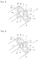
- Fig. 3 and Fig. 4 are respectively III-III line and IV-IV line enlarged cross sections of Fig. 2 .
- Fig. 5 and Fig. 6 are perspective views showing the relations between the drainage hole and the bead part of the drainage structure of the weather strip according to the embodiment of the present invention, of which Fig. 5 shows an upper part of the bead part and Fig. 6 shows a lower part of the bead part.
- the drainage structure of the weather strip according to the embodiment of the present invention relates to vehicles shown in Fig. 8 , of which a soft top 1 that opens or closes is folded and put away in a trunk 2.
- the invention relates to a weather strip 10 having a bead part 30 formed thereon.
- the weather strip 10 is installed on a side edge of a front pillar 4 and a side edge of a soft top 1 as a door 3 opening edge via tape 20 (alternatively, the weather strip 10 may also be fit in holders including retainers).
- the weather strip 10 makes elastic contact with a door glass (side glass) 5 that lifts or lowers when the door 3 is closed to seal outside and inside of the vehicle.
- the weather strip 10 installed on the side edge of the front pillar 4 comprises an extrusion molded part 101 which has die molded parts 102, 103 connected thereto which are respectively on an upper side and a lower side of the vehicle when the weather strip 10 is assembled on the vehicle.
- the die molded part 102 on the upper side is connected to an edge of a header weather strip (not shown) installed on a header 7 which fixes an upper end of a front glass 6 whereas the die molded part 103 on the lower side has a gusset 21 installed thereon, which is unified with a door mirror (not shown).
- the weather strip 10 comprises: an installation base member 11 installed on the door 3 opening edge; a hollow seal part 12 provided downward on an outer-cabin side with respect to said installation base member 11, which makes elastic contact with a top end 5a of a door glass 5; and a seal lip 13 extending from a lower side of the hollow seal part 12 toward an outer-cabin side, of which top end curves upward and makes elastic contact with an inner-cabin side surface of the door glass 5, thereby forming an eaves-trough-shaped water receiving part 14.
- the seal lip 13 has a hollow part 15 provided on an inner-cabin side thereof and the hollow part 15 has a lip 16 on an inner-cabin side thereof which abuts interior material (not shown) including garnish.
- the installation base member 11 On the die molded parts 102, 103, the installation base member 11 has a part thereof split for inserting a core for die molding whereas, on an extrusion molded part 101, the installation base member 11 is connected.
- the installation base member 11 has an outer-cabin side vertical wall 17 provided on a lower side from rough center thereof.
- the outer-cabin side vertical wall 17 has a seal lip 13 provided on top end thereof.
- the hollow seal 12 comprises: an outer-cabin side wall surface 12a that curves from an outer-cabin side edge of the installation base member 11 in such a manner as to project toward the outer-cabin side; and a lower side wall surface 12b of which an outer-cabin side edge is connected to a lower end of the outer-cabin side wall surface 12a whereas an inner-cabin side edge is connected to an upper part of the outer-cabin side vertical wall 17 at a distance from the installation base member 11.
- the top end 5a of the door glass 5 as lifted makes elastic contact with rough center of the lower side wall surface 12b.
- Fig. 7 shows a position with the bead part 30
- Fig. 13 shows another position without the bead part 30.
- the installation base member 11 has an inner-cabin side vertical wall 18 provided on a lower side from the inner-cabin side edge thereof.
- the hollow part 15 is encircled by the outer-cabin side vertical wall 17, the inner-cabin side vertical wall 18, a bottom wall 19 which connects lower ends of the vertical walls 17, 18 and curves downward, and a part of the installation base member 11 on the inner-cabin side.
- the die molded part 103 on the lower side has a drainage hole 22 formed thereon, which bores from the water receiving part 14 to the hollow part 15 so that water 130 guided on the water receiving part 14 from an upper side to a lower side of the weather strip 10 is further guided to the hollow part 15 via the drainage hole 22.
- the water 130 guided to the hollow part 15 is drained outside the vehicle from a front side of the vehicle.
- the drainage hole 22 is rectangular and is formed by removing the outer-cabin side vertical wall 17 together with a part of the water receiving part 14 on the inner-cabin side.
- Examples of the structure of the drainage hole 22 include a structure that a surface which is vertical to a longitudinal direction of the water receiving part 14 is provided and a tunnel is provided on the surface in order to connect the drainage hole 22 and the hollow part 15.
- the bead part 30 is extended to a point in front of the tunnel or an inside of the tunnel.
- the lower side wall surface 12b forming the hollow seal part 12 of the weather strip 10 has a band-like bead part 30 formed thereon, of which inner cabin side is inclined toward the drainage hole 22 and central part protrudes downward thereby forming a projection.
- the bead part 30 extends from an outer-cabin side edge 110 of the lower side wall surface 12b, that is a connecting part of an outer-cabin side wall surface 12a and the lower side wall surface 12b, to an inner-cabin side edge 120 of the lower side wall surface 12b, that is a connecting part of the lower side wall surface 12b with the outer-cabin side vertical wall 17, beyond an elastic contact position with the top end 5a of the door glass 5 toward an inner-cabin side.
- An inner-cabin side edge of the bead part 30 is extended to the point in front of the drainage hole 22.
- the inner-cabin side edge of the bead part 30 may be connected to the drainage hole 22, not extended to the point in front of the drainage hole 22, or extended in such a manner as to protrude inside the drainage hole 22.
- the bead part 30 is die molded simultaneously with the weather strip 10 and made of rubber-like elastic body.
- the top end 5a of the door glass 5 makes elastic contact with the lower side wall surface 12b of the hollow seal part 12 whereas the seal lip 13 makes elastic contact with the inner-cabin side surface of the of the door glass 5.
- the door glass 5 is doubly-sealed on an upper side and a lower side thereof.
- Such a structure prevents the water 130 of rain or car washing from directly entering the inner-cabin side from outer-cabin side. Even in case the water 130 enters the inner-cabin side, the water that flows down the inner-cabin side surface of the door glass 5 is dammed up by the seal lip 13 and is guided to the eaves-trough-shaped water receiving part 14. Therefore, the structure is excellent in water-tightness.
- the lower side wall surface 12b of the hollow seal part 12, with which the top end 5a of the door glass 5 makes elastic contact, has the bead part 30 formed from the outer-cabin side edge 110 to the point in front of the drainage hole 22 beyond the elastic contact position with the top end 5a of the door glass 5 toward the inner-cabin side and the bead part 30 is inclined downward toward the inner-cabin side. Accordingly, when the door glass is closed, the water 130 of rain and car washing, which flows along the soft top 1 toward the outer-cabin side, and the water 130 of car washing directly poured on the weather strip 10 normally collects on the outer-cabin side edge 110 of the lower side wall surface 12b of the hollow seal part 12.
- the water 130 thus collected flows down in a longitudinal direction in which the weather strip 10 extends (in a front direction of the vehicle), is imperatively guided from the outer-cabin side to the inner-cabin side of the door glass 5 along the bead part 30 and is stably guided to the drainage hole 22.
- the bead part 30 bends for the effect of the pressure by the top end 5a of the door glass 5, thereby forming two ditches 31, 32 respectively on both ends of the bead part 30 as shown in Fig. 7 . Accordingly, the water 130, which flows along the bead part 30, flows along the ditches 31, 32 thus formed when the door glass is closed and is stably guided into the drainage hole 22 without water leak into the vehicle interior.
- Such a structure prevents the problem according to the prior art that the water 130 that collects on the outer-cabin side edge 110 of the lower side wall surface 12b of the hollow seal part 12 flows in the longitudinal direction of the weather strip 10, reaches the top end on the front side of the door glass 5, collects on the gusset 21, enters the vehicle interior when the door 3 is opened and causes the water leak.
- a part of the water 130 collected on the outer-cabin side edge 110 of the lower side wall surface 12b of the hollow seal part 12 is transmitted to a space between the top end 5a of the door glass 5 and the lower side wall surface 12b of the hollow seal part 12 for the effect of the capillary phenomenon.
- the water 130 is shut down by the bead part 30 which is on the front side of a water 130 flow direction or facing the water 130 flow direction or is guided to the inner-cabin side along the bead part 30 and further to the drainage hole 22.
- the water 130 which soaks into the soft top 1, especially the soft top 1 made of cloth may collect on the outer-cabin side edge 110 of the lower side wall surface 12b of the hollow seal part 12. But, even while the door glass 5 is open, the water 130 flows down in a longitudinal direction in which the weather strip 10 extends to the bead part 30, is imperatively guided from the outer-cabin side to the inner-cabin side along the bead part 30 and is further guided to the drainage hole 22.
- Such a structure prevents the water 130 from entering the vehicle interior and significantly decreases the amount of the water 130 that drips from the outer-cabin side edge 110 of the lower side wall surface 12b.
- the bead part 30 is made of rubber-like elastic body and is die molded simultaneously with the weather strip 10
- the bead part 30 may be molded separately from the weather strip 10 and adhered on the weather strip 10 after molding, not integrally molded.
- the bead part 30 is not necessarily made of rubber-like elastic body because any bead part 30 as a water course that guides the water 130 from the outer-cabin side beyond the top end 5a of the door glass 5 toward the inner-cabin side performs water-proof effect.
- the inner-cabin side edge of the bead part 30 is extended further than the point in front of the drainage hole 22, but the inner-cabin side edge of the bead part 30 may be extended at least beyond the elastic contact position with the top end 5a of the door glass 5 toward the inner-cabin side. More specifically, the water 130 guided to the bead part 30: directly falls into the eaves-trough-shaped water receiving part 14; falls down from the inner-cabin side of the lower side wall surface 12b along the outer-cabin side vertical wall 17; or falls down the inner-cabin side surface of the door glass 5, is dammed up by the seal lip 13 and guided into the eaves-trough-shaped water receiving part 14. Such a structure prevents the water 130 from entering the vehicle interior and causing water leak.
- the inner-cabin side edge of the bead part 30 is extended to the inner-cabin side surface of the door glass 5 or to an upper side of a line in a vertical direction of the water receiving part 14, the water 130 which flows along the bead part 30 directly falls or is easily guided to the water receiving part 14 from the inner-cabin side of the lower side wall surface 12b along the outer-cabin side vertical wall 17. Accordingly, the amount of the water 130 is decreased, which is transmitted along the inner-cabin side surface of the door glass 5, dammed up by the seal lip 13 and guided to the water receiving part 14. Such a structure reduces the burden of sealing function of the seal lip 13.
- the lower side wall surface 12b has the bead part 30 formed at least on the elastic contact position thereof with the top end 5a of the door glass 5
- the lower side wall surface 12b bends, thereby forming two ditches 31, 32 respectively on both ends of the bead part 30 when the top end 5a of the door glass 5 abuts the bead part 30. Accordingly, the water 130 which flows along the edge of the top end of the door glass flows down the inner-cabin side or the outer-cabin side via the two ditches 31, 32 thus formed, thereby preventing the water 130 from entering the vehicle interior.
- the bead part 30 is formed on the die molded part 103 on the lower side of the weather strip 10 installed on the side edge of the front pillar 4 of the retractable roof vehicle for guiding the water 130 to the drainage hole 22 along bead part 30.
- the bead part 30 or a combination of the bead part 30 and the drainage hole 22 in the same manner as formed on the die molded part 103 on the lower side may be formed on a die molded part 102 on the upper side, on the weather strip installed on the side edge of the roof or on the weather strip installed on the side edge of the rear pillar and may be formed on the extrusion molded part or the die molded part.
- the bead part 30 or a combination of the bead part 30 and the drainage hole 22 may be provided on a plurality of parts, not only a singular part.
- the plurality of bead part 30 may be provided by providing one bead part 30 on the die molded part 103 on the lower side of the weather strip 10 and the other bead part 30 on the die molded part 102 on the upper side.
- the water 130 flowing down from the soft top 1 is guided to the water receiving part 14 on the inner-cabin side by the bead part 30 or flows down the outer-cabin side surface of the door glass 5 to the outer-cabin side.
- the water 130 that collects between the bead part 30 provided on the die molded part 102 on the upper side and the bead part 30 provided on the die molded part 103 on the lower side or the water 130 that remains and flows down from the soft top 1 is guided to the water receiving part 14 on the inner-cabin side.
- the water 130 is flowed down the outer-cabin side surface of the door glass 5 to the outer-cabin side. Accordingly, the water 130 is guided through two stages. Further, a plurality of bead parts 30, two or three for example, adjacent to each other may be consecutively provided.
- the bead part 30 is not necessarily provided in combination with the drainage hole 22 because the bead part 30, which extends from the outer-cabin side beyond the elastic contact position with the top end 5a of the door glass 5 toward the inner-cabin side, guides the water 130 flowing along the bead part 30 to the water receiving part 14 without fail.
- the bead part 30 may be extended to the water receiving part 14 for guiding the water 130 to the water receiving part 14.
- Examples of positions for providing the combination of the bead part 30 and the drainage hole 22 on the extrusion molded part include the center of the extrusion molded part 101 in Fig. 1 .
- the present invention may be adopted on the retractable roof vehicle including: a soft top roof; a roof comprising a roof panel and a back window panel at the back of the roof panel which are folded and put away in the trunk 2 while the roof panel as folded is piled on the back window panel; and a removal roof.
- the formation of the bead part is not limited on the weather strip installed on the retractable roof vehicle and may be formed on the weather strips installed on the side edge of the front pillar, the side edge of the roof and the side edge of the rear pillar of the hard top vehicle.
Landscapes
- Engineering & Computer Science (AREA)
- Mechanical Engineering (AREA)
- Seal Device For Vehicle (AREA)
Applications Claiming Priority (1)
| Application Number | Priority Date | Filing Date | Title |
|---|---|---|---|
| JP2010285886A JP5711528B2 (ja) | 2010-12-22 | 2010-12-22 | ウェザーストリップの排水構造 |
Publications (3)
| Publication Number | Publication Date |
|---|---|
| EP2468551A2 true EP2468551A2 (de) | 2012-06-27 |
| EP2468551A3 EP2468551A3 (de) | 2015-04-01 |
| EP2468551B1 EP2468551B1 (de) | 2018-11-07 |
Family
ID=45093355
Family Applications (1)
| Application Number | Title | Priority Date | Filing Date |
|---|---|---|---|
| EP11189116.4A Active EP2468551B1 (de) | 2010-12-22 | 2011-11-15 | Entwässerungsstruktur eines Dichtungsstreifens |
Country Status (4)
| Country | Link |
|---|---|
| US (1) | US8479450B2 (de) |
| EP (1) | EP2468551B1 (de) |
| JP (1) | JP5711528B2 (de) |
| CN (1) | CN202493200U (de) |
Cited By (3)
| Publication number | Priority date | Publication date | Assignee | Title |
|---|---|---|---|---|
| ES2568554A1 (es) * | 2015-12-22 | 2016-04-29 | Seat, S.A. | Sistema de drenaje para elemento móvil de carrocería de vehículos |
| EP3050730A1 (de) * | 2015-02-02 | 2016-08-03 | Nishikawa Rubber Co., Ltd. | Dichtungsstreifen |
| EP3050728A1 (de) * | 2015-02-02 | 2016-08-03 | Nishikawa Rubber Co., Ltd. | Dichtungsstruktur für nicht feststehendes dach |
Families Citing this family (17)
| Publication number | Priority date | Publication date | Assignee | Title |
|---|---|---|---|---|
| JP5832851B2 (ja) * | 2011-10-21 | 2015-12-16 | 西川ゴム工業株式会社 | 自動車用のドアウェザストリップ |
| JP6322371B2 (ja) * | 2012-08-29 | 2018-05-09 | 西川ゴム工業株式会社 | ドアウェザーストリップ |
| JP6080433B2 (ja) * | 2012-08-29 | 2017-02-15 | Dnp田村プラスチック株式会社 | 自動車用サイドバイザー |
| JP5626310B2 (ja) * | 2012-10-23 | 2014-11-19 | トヨタ自動車株式会社 | 車両用ドア構造 |
| JP5806699B2 (ja) * | 2013-04-11 | 2015-11-10 | 東海興業株式会社 | 成形品 |
| US9724987B2 (en) * | 2013-09-02 | 2017-08-08 | Honda Motor Co., Ltd. | Weather strip |
| US10081232B2 (en) * | 2014-06-11 | 2018-09-25 | Nishikawa Rubber Co., Ltd. | Weatherstrip assembly for a vehicle |
| JP2017077850A (ja) * | 2015-10-22 | 2017-04-27 | 本田技研工業株式会社 | ドアシール構造 |
| US9987911B2 (en) * | 2016-02-18 | 2018-06-05 | Inalfa Roof Systems Group B.V. | Open roof construction for a vehicle |
| JP6749800B2 (ja) * | 2016-06-28 | 2020-09-02 | 西川ゴム工業株式会社 | ウェザーストリップ |
| US9840287B1 (en) * | 2016-11-14 | 2017-12-12 | Ford Global Technologies, Llc | Fluid management system for a windshield wrapped vehicle pillar |
| JP6819350B2 (ja) * | 2017-02-20 | 2021-01-27 | 三菱自動車工業株式会社 | ドアの排水構造 |
| EP3711650B1 (de) * | 2018-01-30 | 2024-03-06 | Foshan Shunde Midea Washing Appliances Manufacturing Co., Ltd. | Dichtungsstreifen für geschirrspülmaschine und geschirrspülmaschine damit |
| JP7171377B2 (ja) * | 2018-11-14 | 2022-11-15 | 西川ゴム工業株式会社 | ドアウェザーストリップ |
| JP7221753B2 (ja) * | 2019-03-21 | 2023-02-14 | 西川ゴム工業株式会社 | タッチセンサー付きスライドドアのシール構造 |
| CN110154705A (zh) * | 2019-06-28 | 2019-08-23 | 长城华冠汽车科技(苏州)有限公司 | 车玻璃密封机构和汽车 |
| CN113580897A (zh) * | 2020-04-30 | 2021-11-02 | 韦巴斯托股份公司 | 用于具有顶开口的车顶的顶组件 |
Citations (2)
| Publication number | Priority date | Publication date | Assignee | Title |
|---|---|---|---|---|
| JPH1071860A (ja) | 1996-09-02 | 1998-03-17 | Nishikawa Rubber Co Ltd | ウェザストリップの型成形部 |
| JP2006264594A (ja) | 2005-03-25 | 2006-10-05 | Nishikawa Rubber Co Ltd | オープンカー用ウェザーストリップ及びその製造方法 |
Family Cites Families (18)
| Publication number | Priority date | Publication date | Assignee | Title |
|---|---|---|---|---|
| US1429203A (en) * | 1919-11-11 | 1922-09-12 | Hartstra Johannes | Weather strip |
| DE2943248A1 (de) * | 1979-10-26 | 1981-05-14 | Daimler-Benz Ag, 7000 Stuttgart | Kraftwagenfenster, insbesondere heckfenster |
| US4919471A (en) * | 1988-03-16 | 1990-04-24 | Kinugawa Rubber Industrial Co., Ltd. | Weatherstrip for sashless door in automotive vehicles |
| US5129193A (en) * | 1988-12-27 | 1992-07-14 | Ford Motor Company | Sealing system for movable dual pane glass |
| JPH0714043Y2 (ja) * | 1989-09-30 | 1995-04-05 | 豊田合成株式会社 | ガラスラン |
| US5010689A (en) * | 1990-03-19 | 1991-04-30 | The Standard Products Company | Glass run channel |
| FR2667828A1 (fr) * | 1990-10-15 | 1992-04-17 | Smadja Jean Claude | Joint d'etancheite pour vitres coulissantes de vehicules. |
| JP3249199B2 (ja) * | 1992-09-11 | 2002-01-21 | 本田技研工業株式会社 | オープンカーのシール構造 |
| JPH0642360U (ja) * | 1992-11-25 | 1994-06-03 | 関東自動車工業株式会社 | 車両用ドアのガラスラン構造 |
| JP3013700B2 (ja) * | 1994-04-28 | 2000-02-28 | 豊田合成株式会社 | ゴム成形品の成形用型 |
| US6189950B1 (en) * | 1997-10-29 | 2001-02-20 | Nishikawa Rubber Co., Ltd. | Sealing structure for a convertible |
| JP3314020B2 (ja) * | 1997-10-29 | 2002-08-12 | 西川ゴム工業株式会社 | オープンカーのシール構造 |
| JP2000025462A (ja) * | 1998-07-15 | 2000-01-25 | Toyoda Gosei Co Ltd | ガラスラン |
| JP3749382B2 (ja) * | 1998-08-04 | 2006-02-22 | 西川ゴム工業株式会社 | 非固定式ルーフのシール構造 |
| JP4211522B2 (ja) * | 2003-07-11 | 2009-01-21 | 豊田合成株式会社 | ドアウエザストリップ |
| JP2006001406A (ja) * | 2004-06-17 | 2006-01-05 | Nishikawa Rubber Co Ltd | ウェザーストリップ |
| JP4882740B2 (ja) * | 2006-12-28 | 2012-02-22 | 豊田合成株式会社 | 自動車用ルーフサイドウエザストリップ |
| JP2010076701A (ja) * | 2008-09-29 | 2010-04-08 | Toyoda Gosei Co Ltd | 固定ガラス用ウエザストリップ |
-
2010
- 2010-12-22 JP JP2010285886A patent/JP5711528B2/ja active Active
-
2011
- 2011-11-15 EP EP11189116.4A patent/EP2468551B1/de active Active
- 2011-11-17 US US13/298,900 patent/US8479450B2/en active Active
- 2011-11-21 CN CN201120503805XU patent/CN202493200U/zh not_active Expired - Fee Related
Patent Citations (2)
| Publication number | Priority date | Publication date | Assignee | Title |
|---|---|---|---|---|
| JPH1071860A (ja) | 1996-09-02 | 1998-03-17 | Nishikawa Rubber Co Ltd | ウェザストリップの型成形部 |
| JP2006264594A (ja) | 2005-03-25 | 2006-10-05 | Nishikawa Rubber Co Ltd | オープンカー用ウェザーストリップ及びその製造方法 |
Cited By (3)
| Publication number | Priority date | Publication date | Assignee | Title |
|---|---|---|---|---|
| EP3050730A1 (de) * | 2015-02-02 | 2016-08-03 | Nishikawa Rubber Co., Ltd. | Dichtungsstreifen |
| EP3050728A1 (de) * | 2015-02-02 | 2016-08-03 | Nishikawa Rubber Co., Ltd. | Dichtungsstruktur für nicht feststehendes dach |
| ES2568554A1 (es) * | 2015-12-22 | 2016-04-29 | Seat, S.A. | Sistema de drenaje para elemento móvil de carrocería de vehículos |
Also Published As
| Publication number | Publication date |
|---|---|
| US20120159858A1 (en) | 2012-06-28 |
| JP2012131396A (ja) | 2012-07-12 |
| EP2468551B1 (de) | 2018-11-07 |
| JP5711528B2 (ja) | 2015-04-30 |
| CN202493200U (zh) | 2012-10-17 |
| EP2468551A3 (de) | 2015-04-01 |
| US8479450B2 (en) | 2013-07-09 |
Similar Documents
| Publication | Publication Date | Title |
|---|---|---|
| EP2468551B1 (de) | Entwässerungsstruktur eines Dichtungsstreifens | |
| US8869457B2 (en) | Assembly structure of weather strip | |
| US8782955B2 (en) | Sealing structure of weather strip for retractable roof vehicles | |
| US8434813B2 (en) | Drainage structure of weather strip | |
| EP3050728B1 (de) | Dichtungsstruktur für nicht feststehendes dach | |
| US10940746B2 (en) | Door weather strip | |
| US5105580A (en) | Weather strip for motor vehicle | |
| EP3050730B1 (de) | Dichtungsstreifen | |
| US11351848B2 (en) | Sealing structure for truck cargo bed with shutter | |
| JP5337444B2 (ja) | 車両の排水構造 | |
| JP5003966B2 (ja) | 可動ルーフパネルの排水構造 | |
| JPH0840076A (ja) | サンルーフのサンルーフフレーム構造 | |
| KR100837960B1 (ko) | 선루프의 배수구조 | |
| JP5476154B2 (ja) | ドアウェザーストリップ | |
| JP2006327564A (ja) | ウェザーストリップの排水構造。 | |
| JP4313291B2 (ja) | 車両用ウインドガラスの水切り構造 | |
| CN215921843U (zh) | 一种车顶天窗排水系统 | |
| JP2020164001A (ja) | クォータガラスウェザストリップ | |
| JP2008149800A (ja) | ウェザストリップ | |
| JP2007284009A (ja) | 自動車シール材 | |
| JP2009012727A (ja) | 格納式ルーフ車両の排水構造 | |
| JPS6349645B2 (de) | ||
| JPS58118416A (ja) | ドアウエザ−ストリツプ | |
| JP2009012725A (ja) | 格納式ルーフ車両の排水構造 |
Legal Events
| Date | Code | Title | Description |
|---|---|---|---|
| AK | Designated contracting states |
Kind code of ref document: A2 Designated state(s): AL AT BE BG CH CY CZ DE DK EE ES FI FR GB GR HR HU IE IS IT LI LT LU LV MC MK MT NL NO PL PT RO RS SE SI SK SM TR |
|
| AX | Request for extension of the european patent |
Extension state: BA ME |
|
| PUAI | Public reference made under article 153(3) epc to a published international application that has entered the european phase |
Free format text: ORIGINAL CODE: 0009012 |
|
| PUAL | Search report despatched |
Free format text: ORIGINAL CODE: 0009013 |
|
| AK | Designated contracting states |
Kind code of ref document: A3 Designated state(s): AL AT BE BG CH CY CZ DE DK EE ES FI FR GB GR HR HU IE IS IT LI LT LU LV MC MK MT NL NO PL PT RO RS SE SI SK SM TR |
|
| AX | Request for extension of the european patent |
Extension state: BA ME |
|
| RIC1 | Information provided on ipc code assigned before grant |
Ipc: B60J 10/00 20060101ALI20150224BHEP Ipc: B60J 10/06 20060101ALI20150224BHEP Ipc: B60J 10/08 20060101AFI20150224BHEP |
|
| 17P | Request for examination filed |
Effective date: 20150930 |
|
| 17Q | First examination report despatched |
Effective date: 20170919 |
|
| REG | Reference to a national code |
Ref country code: DE Ref legal event code: R079 Ref document number: 602011053588 Country of ref document: DE Free format text: PREVIOUS MAIN CLASS: B60J0010080000 Ipc: B60J0010240000 |
|
| GRAP | Despatch of communication of intention to grant a patent |
Free format text: ORIGINAL CODE: EPIDOSNIGR1 |
|
| RIC1 | Information provided on ipc code assigned before grant |
Ipc: B60J 10/25 20160101ALI20180711BHEP Ipc: B60J 10/77 20160101ALI20180711BHEP Ipc: B60J 10/24 20160101AFI20180711BHEP Ipc: B60J 10/86 20160101ALI20180711BHEP |
|
| INTG | Intention to grant announced |
Effective date: 20180810 |
|
| GRAS | Grant fee paid |
Free format text: ORIGINAL CODE: EPIDOSNIGR3 |
|
| GRAA | (expected) grant |
Free format text: ORIGINAL CODE: 0009210 |
|
| AK | Designated contracting states |
Kind code of ref document: B1 Designated state(s): AL AT BE BG CH CY CZ DE DK EE ES FI FR GB GR HR HU IE IS IT LI LT LU LV MC MK MT NL NO PL PT RO RS SE SI SK SM TR |
|
| REG | Reference to a national code |
Ref country code: GB Ref legal event code: FG4D |
|
| REG | Reference to a national code |
Ref country code: CH Ref legal event code: EP Ref country code: AT Ref legal event code: REF Ref document number: 1061627 Country of ref document: AT Kind code of ref document: T Effective date: 20181115 |
|
| REG | Reference to a national code |
Ref country code: DE Ref legal event code: R096 Ref document number: 602011053588 Country of ref document: DE |
|
| REG | Reference to a national code |
Ref country code: IE Ref legal event code: FG4D |
|
| REG | Reference to a national code |
Ref country code: NL Ref legal event code: MP Effective date: 20181107 |
|
| REG | Reference to a national code |
Ref country code: LT Ref legal event code: MG4D |
|
| REG | Reference to a national code |
Ref country code: AT Ref legal event code: MK05 Ref document number: 1061627 Country of ref document: AT Kind code of ref document: T Effective date: 20181107 |
|
| PG25 | Lapsed in a contracting state [announced via postgrant information from national office to epo] |
Ref country code: LT Free format text: LAPSE BECAUSE OF FAILURE TO SUBMIT A TRANSLATION OF THE DESCRIPTION OR TO PAY THE FEE WITHIN THE PRESCRIBED TIME-LIMIT Effective date: 20181107 Ref country code: HR Free format text: LAPSE BECAUSE OF FAILURE TO SUBMIT A TRANSLATION OF THE DESCRIPTION OR TO PAY THE FEE WITHIN THE PRESCRIBED TIME-LIMIT Effective date: 20181107 Ref country code: LV Free format text: LAPSE BECAUSE OF FAILURE TO SUBMIT A TRANSLATION OF THE DESCRIPTION OR TO PAY THE FEE WITHIN THE PRESCRIBED TIME-LIMIT Effective date: 20181107 Ref country code: NO Free format text: LAPSE BECAUSE OF FAILURE TO SUBMIT A TRANSLATION OF THE DESCRIPTION OR TO PAY THE FEE WITHIN THE PRESCRIBED TIME-LIMIT Effective date: 20190207 Ref country code: IS Free format text: LAPSE BECAUSE OF FAILURE TO SUBMIT A TRANSLATION OF THE DESCRIPTION OR TO PAY THE FEE WITHIN THE PRESCRIBED TIME-LIMIT Effective date: 20190307 Ref country code: FI Free format text: LAPSE BECAUSE OF FAILURE TO SUBMIT A TRANSLATION OF THE DESCRIPTION OR TO PAY THE FEE WITHIN THE PRESCRIBED TIME-LIMIT Effective date: 20181107 Ref country code: AT Free format text: LAPSE BECAUSE OF FAILURE TO SUBMIT A TRANSLATION OF THE DESCRIPTION OR TO PAY THE FEE WITHIN THE PRESCRIBED TIME-LIMIT Effective date: 20181107 Ref country code: ES Free format text: LAPSE BECAUSE OF FAILURE TO SUBMIT A TRANSLATION OF THE DESCRIPTION OR TO PAY THE FEE WITHIN THE PRESCRIBED TIME-LIMIT Effective date: 20181107 Ref country code: BG Free format text: LAPSE BECAUSE OF FAILURE TO SUBMIT A TRANSLATION OF THE DESCRIPTION OR TO PAY THE FEE WITHIN THE PRESCRIBED TIME-LIMIT Effective date: 20190207 |
|
| PG25 | Lapsed in a contracting state [announced via postgrant information from national office to epo] |
Ref country code: AL Free format text: LAPSE BECAUSE OF FAILURE TO SUBMIT A TRANSLATION OF THE DESCRIPTION OR TO PAY THE FEE WITHIN THE PRESCRIBED TIME-LIMIT Effective date: 20181107 Ref country code: NL Free format text: LAPSE BECAUSE OF FAILURE TO SUBMIT A TRANSLATION OF THE DESCRIPTION OR TO PAY THE FEE WITHIN THE PRESCRIBED TIME-LIMIT Effective date: 20181107 Ref country code: PT Free format text: LAPSE BECAUSE OF FAILURE TO SUBMIT A TRANSLATION OF THE DESCRIPTION OR TO PAY THE FEE WITHIN THE PRESCRIBED TIME-LIMIT Effective date: 20190307 Ref country code: SE Free format text: LAPSE BECAUSE OF FAILURE TO SUBMIT A TRANSLATION OF THE DESCRIPTION OR TO PAY THE FEE WITHIN THE PRESCRIBED TIME-LIMIT Effective date: 20181107 Ref country code: RS Free format text: LAPSE BECAUSE OF FAILURE TO SUBMIT A TRANSLATION OF THE DESCRIPTION OR TO PAY THE FEE WITHIN THE PRESCRIBED TIME-LIMIT Effective date: 20181107 Ref country code: GR Free format text: LAPSE BECAUSE OF FAILURE TO SUBMIT A TRANSLATION OF THE DESCRIPTION OR TO PAY THE FEE WITHIN THE PRESCRIBED TIME-LIMIT Effective date: 20190208 |
|
| REG | Reference to a national code |
Ref country code: CH Ref legal event code: PL |
|
| PG25 | Lapsed in a contracting state [announced via postgrant information from national office to epo] |
Ref country code: PL Free format text: LAPSE BECAUSE OF FAILURE TO SUBMIT A TRANSLATION OF THE DESCRIPTION OR TO PAY THE FEE WITHIN THE PRESCRIBED TIME-LIMIT Effective date: 20181107 Ref country code: LU Free format text: LAPSE BECAUSE OF NON-PAYMENT OF DUE FEES Effective date: 20181115 Ref country code: CZ Free format text: LAPSE BECAUSE OF FAILURE TO SUBMIT A TRANSLATION OF THE DESCRIPTION OR TO PAY THE FEE WITHIN THE PRESCRIBED TIME-LIMIT Effective date: 20181107 Ref country code: DK Free format text: LAPSE BECAUSE OF FAILURE TO SUBMIT A TRANSLATION OF THE DESCRIPTION OR TO PAY THE FEE WITHIN THE PRESCRIBED TIME-LIMIT Effective date: 20181107 Ref country code: IT Free format text: LAPSE BECAUSE OF FAILURE TO SUBMIT A TRANSLATION OF THE DESCRIPTION OR TO PAY THE FEE WITHIN THE PRESCRIBED TIME-LIMIT Effective date: 20181107 |
|
| REG | Reference to a national code |
Ref country code: DE Ref legal event code: R097 Ref document number: 602011053588 Country of ref document: DE |
|
| REG | Reference to a national code |
Ref country code: BE Ref legal event code: MM Effective date: 20181130 |
|
| REG | Reference to a national code |
Ref country code: IE Ref legal event code: MM4A |
|
| PG25 | Lapsed in a contracting state [announced via postgrant information from national office to epo] |
Ref country code: LI Free format text: LAPSE BECAUSE OF NON-PAYMENT OF DUE FEES Effective date: 20181130 Ref country code: MC Free format text: LAPSE BECAUSE OF FAILURE TO SUBMIT A TRANSLATION OF THE DESCRIPTION OR TO PAY THE FEE WITHIN THE PRESCRIBED TIME-LIMIT Effective date: 20181107 Ref country code: EE Free format text: LAPSE BECAUSE OF FAILURE TO SUBMIT A TRANSLATION OF THE DESCRIPTION OR TO PAY THE FEE WITHIN THE PRESCRIBED TIME-LIMIT Effective date: 20181107 Ref country code: SM Free format text: LAPSE BECAUSE OF FAILURE TO SUBMIT A TRANSLATION OF THE DESCRIPTION OR TO PAY THE FEE WITHIN THE PRESCRIBED TIME-LIMIT Effective date: 20181107 Ref country code: SK Free format text: LAPSE BECAUSE OF FAILURE TO SUBMIT A TRANSLATION OF THE DESCRIPTION OR TO PAY THE FEE WITHIN THE PRESCRIBED TIME-LIMIT Effective date: 20181107 Ref country code: RO Free format text: LAPSE BECAUSE OF FAILURE TO SUBMIT A TRANSLATION OF THE DESCRIPTION OR TO PAY THE FEE WITHIN THE PRESCRIBED TIME-LIMIT Effective date: 20181107 Ref country code: CH Free format text: LAPSE BECAUSE OF NON-PAYMENT OF DUE FEES Effective date: 20181130 |
|
| PLBE | No opposition filed within time limit |
Free format text: ORIGINAL CODE: 0009261 |
|
| STAA | Information on the status of an ep patent application or granted ep patent |
Free format text: STATUS: NO OPPOSITION FILED WITHIN TIME LIMIT |
|
| 26N | No opposition filed |
Effective date: 20190808 |
|
| GBPC | Gb: european patent ceased through non-payment of renewal fee |
Effective date: 20190207 |
|
| PG25 | Lapsed in a contracting state [announced via postgrant information from national office to epo] |
Ref country code: FR Free format text: LAPSE BECAUSE OF NON-PAYMENT OF DUE FEES Effective date: 20190107 Ref country code: SI Free format text: LAPSE BECAUSE OF FAILURE TO SUBMIT A TRANSLATION OF THE DESCRIPTION OR TO PAY THE FEE WITHIN THE PRESCRIBED TIME-LIMIT Effective date: 20181107 Ref country code: IE Free format text: LAPSE BECAUSE OF NON-PAYMENT OF DUE FEES Effective date: 20181115 |
|
| PG25 | Lapsed in a contracting state [announced via postgrant information from national office to epo] |
Ref country code: BE Free format text: LAPSE BECAUSE OF NON-PAYMENT OF DUE FEES Effective date: 20181130 |
|
| PG25 | Lapsed in a contracting state [announced via postgrant information from national office to epo] |
Ref country code: GB Free format text: LAPSE BECAUSE OF NON-PAYMENT OF DUE FEES Effective date: 20190207 Ref country code: MT Free format text: LAPSE BECAUSE OF NON-PAYMENT OF DUE FEES Effective date: 20181115 |
|
| PG25 | Lapsed in a contracting state [announced via postgrant information from national office to epo] |
Ref country code: TR Free format text: LAPSE BECAUSE OF FAILURE TO SUBMIT A TRANSLATION OF THE DESCRIPTION OR TO PAY THE FEE WITHIN THE PRESCRIBED TIME-LIMIT Effective date: 20181107 |
|
| PG25 | Lapsed in a contracting state [announced via postgrant information from national office to epo] |
Ref country code: CY Free format text: LAPSE BECAUSE OF FAILURE TO SUBMIT A TRANSLATION OF THE DESCRIPTION OR TO PAY THE FEE WITHIN THE PRESCRIBED TIME-LIMIT Effective date: 20181107 Ref country code: HU Free format text: LAPSE BECAUSE OF FAILURE TO SUBMIT A TRANSLATION OF THE DESCRIPTION OR TO PAY THE FEE WITHIN THE PRESCRIBED TIME-LIMIT; INVALID AB INITIO Effective date: 20111115 Ref country code: MK Free format text: LAPSE BECAUSE OF NON-PAYMENT OF DUE FEES Effective date: 20181107 |
|
| PGFP | Annual fee paid to national office [announced via postgrant information from national office to epo] |
Ref country code: DE Payment date: 20230929 Year of fee payment: 13 |