EP2462058B1 - Verfahren und anlage zur herstellung von trichlorsilan - Google Patents
Verfahren und anlage zur herstellung von trichlorsilan Download PDFInfo
- Publication number
- EP2462058B1 EP2462058B1 EP10739921.4A EP10739921A EP2462058B1 EP 2462058 B1 EP2462058 B1 EP 2462058B1 EP 10739921 A EP10739921 A EP 10739921A EP 2462058 B1 EP2462058 B1 EP 2462058B1
- Authority
- EP
- European Patent Office
- Prior art keywords
- reactor
- silicon particles
- trichlorosilane
- hydrogen
- fluidized
- Prior art date
- Legal status (The legal status is an assumption and is not a legal conclusion. Google has not performed a legal analysis and makes no representation as to the accuracy of the status listed.)
- Active
Links
Images
Classifications
-
- C—CHEMISTRY; METALLURGY
- C01—INORGANIC CHEMISTRY
- C01B—NON-METALLIC ELEMENTS; COMPOUNDS THEREOF; METALLOIDS OR COMPOUNDS THEREOF NOT COVERED BY SUBCLASS C01C
- C01B33/00—Silicon; Compounds thereof
- C01B33/08—Compounds containing halogen
- C01B33/107—Halogenated silanes
- C01B33/1071—Tetrachloride, trichlorosilane or silicochloroform, dichlorosilane, monochlorosilane or mixtures thereof
-
- C—CHEMISTRY; METALLURGY
- C01—INORGANIC CHEMISTRY
- C01B—NON-METALLIC ELEMENTS; COMPOUNDS THEREOF; METALLOIDS OR COMPOUNDS THEREOF NOT COVERED BY SUBCLASS C01C
- C01B33/00—Silicon; Compounds thereof
- C01B33/08—Compounds containing halogen
- C01B33/107—Halogenated silanes
-
- B—PERFORMING OPERATIONS; TRANSPORTING
- B01—PHYSICAL OR CHEMICAL PROCESSES OR APPARATUS IN GENERAL
- B01D—SEPARATION
- B01D46/00—Filters or filtering processes specially modified for separating dispersed particles from gases or vapours
- B01D46/30—Particle separators, e.g. dust precipitators, using loose filtering material
- B01D46/32—Particle separators, e.g. dust precipitators, using loose filtering material the material moving during filtering
- B01D46/38—Particle separators, e.g. dust precipitators, using loose filtering material the material moving during filtering as fluidised bed
-
- B—PERFORMING OPERATIONS; TRANSPORTING
- B01—PHYSICAL OR CHEMICAL PROCESSES OR APPARATUS IN GENERAL
- B01J—CHEMICAL OR PHYSICAL PROCESSES, e.g. CATALYSIS OR COLLOID CHEMISTRY; THEIR RELEVANT APPARATUS
- B01J19/00—Chemical, physical or physico-chemical processes in general; Their relevant apparatus
- B01J19/24—Stationary reactors without moving elements inside
-
- C—CHEMISTRY; METALLURGY
- C01—INORGANIC CHEMISTRY
- C01B—NON-METALLIC ELEMENTS; COMPOUNDS THEREOF; METALLOIDS OR COMPOUNDS THEREOF NOT COVERED BY SUBCLASS C01C
- C01B33/00—Silicon; Compounds thereof
- C01B33/08—Compounds containing halogen
- C01B33/107—Halogenated silanes
- C01B33/1071—Tetrachloride, trichlorosilane or silicochloroform, dichlorosilane, monochlorosilane or mixtures thereof
- C01B33/10742—Tetrachloride, trichlorosilane or silicochloroform, dichlorosilane, monochlorosilane or mixtures thereof prepared by hydrochlorination of silicon or of a silicon-containing material
- C01B33/10757—Tetrachloride, trichlorosilane or silicochloroform, dichlorosilane, monochlorosilane or mixtures thereof prepared by hydrochlorination of silicon or of a silicon-containing material with the preferential formation of trichlorosilane
- C01B33/10763—Tetrachloride, trichlorosilane or silicochloroform, dichlorosilane, monochlorosilane or mixtures thereof prepared by hydrochlorination of silicon or of a silicon-containing material with the preferential formation of trichlorosilane from silicon
Definitions
- the present invention is a process for the preparation of trichlorosilane by preferably catalytic reaction of silicon particles with tetrachlorosilane and hydrogen in a fluidized bed reactor and a system in which such a method can be operated.
- trichlorosilane is a valuable intermediate in the production of high purity silicon, as required for photovoltaic applications and for semiconductor technology as well as in silicon organics.
- metallurgical silicon which often still has a relatively high proportion of impurities, can be converted into trichlorosilane, which is then reduced with water to high-purity silicon.
- high-purity silicon by thermal decomposition of monosilane, as z. B. in the DE 33 11 650 is described.
- the monosilane required for this purpose can in turn be obtained in particular by disproportionation of trichlorosilane.
- the hydrogenation variant is very common, since the silicon tetrachloride required for the disproportionation of trichlorosilane inevitably as a by-product to monosilane (as in virtually all processes for the production of polysilicon) is obtained anyway.
- the total yield of the synthesis chain Si + SiCl 4 + H 2 SiSiHCl 3 SiSiH 4 + SiCl 4 SiSi can, of course, be significantly increased by reintroducing the silicon tetrachloride into the reaction path during the disproportionation.
- a suitable fluidized bed reactor is for example from DE 196 47 162 A1 or the DE 196 47 154 A1 known.
- Such a reactor generally comprises a reaction space in whose lower area a distributor plate is provided, via which hydrogen gas and vaporous silicon tetrachloride can be flowed into the reaction space. Silicon particles can be transferred via a suitable inlet directly into the reaction space. Due to the upwardly flowing gas mixture of hydrogen and vaporous silicon tetrachloride, the silicon particles are converted into a fluidized state and form a fluidized bed.
- the trichlorosilane formed in the fluidized bed (and optionally other reaction products) is generally removed from the reactor via an outlet in the upper region of the fluidized-bed reactor.
- the problem is that, especially at higher gas velocities always fine silicon particles are entrained from the fluidized bed and escape together with the trichlorosilane-containing product gas stream from the reactor. So that this loss does not get out of hand, fluidized bed reactors for the synthesis of trichlorosilane are usually provided with particle separators such as cyclones.
- Suitable cyclones typically include a cyclone body having a gas inlet, a gas outlet, a particle drop outlet, and a particle discharge tube, the upper end of which is connected to the particle drop outlet of the cyclone body communicated.
- a dust funnel is inserted between the cyclone body and the P
- the cyclone body, the dust funnel and the Pumbleabriosrohr are usually arranged in the reaction space of the fluidized bed reactor, that the cyclone body is in an upper part of the reaction space, ideally above the fluidized bed formed in the reaction chamber.
- the mean particle diameter of the silicon particles introduced into the reaction space is between approximately 100 and 400 ⁇ m.
- the size of the particles reduces, particles with sizes of e.g. Less than 10 microns then occur increasingly.
- particles of such a size are entrained with the trichlorosilane-containing product gas stream and enter the cyclone body of the cyclone.
- a process for the production of trichlorosilane by reacting silicon with silicon tetrachloride and hydrogen with the addition of hydrogen chloride in a fluidized bed reactor is known in which the residence time of the hydrogen chloride is lowered in the reactor compared to that of silicon tetrachloride.
- the Trichlorsilanausbeute is thereby increased.
- silicon particles discharged from the reactor are separated from the gas stream by means of a particle separator and returned to the reactor. In this case, immediately before or after the separator to the gas stream leading to the silicon particles hydrogen chloride can be added.
- the method according to the invention makes use of a fluidized-bed reactor in which silicon particles are reacted with tetrachlorosilane and hydrogen and optionally with hydrogen chloride to give a product gas stream containing trichlorosilane.
- the presence of hydrogen chloride is generally not mandatory, but may have a positive effect especially when starting the reactor.
- the fluidized bed reactor used has at least one inlet for the tetrachlorosilane and the hydrogen, in particular a vapor-gas mixture of both, and optionally the hydrogen chloride and at least one inlet for the silicon particles.
- At least the At least one inlet for the tetrachlorosilane and the hydrogen is preferably arranged in the bottom region of the fluidized bed reactor, so that the tetrachlorosilane and the hydrogen can flow upwards within the fluidized bed reactor. Introduced into the reactor silicon particles can then form a fluidized bed with the tetrachlorosilane and the hydrogen.
- the reaction of the silicon particles with tetrachlorosilane and hydrogen and optionally with hydrogen chloride is carried out under catalytic conditions.
- catalysts are iron- and / or copper-containing catalysts, the latter being preferably used.
- metallic iron is suitable as the copper-containing catalyst metallic copper (for example in the form of copper powder or copper flakes) or a copper compound.
- the catalyst may be introduced separately into the fluidized bed reactor or be pre-mixed with the Siliziumpartiklen.
- the fluidized bed reactor used furthermore has at least one outlet for the trichlorosilane-containing product gas stream.
- a trichlorosilane-containing product gas stream usually always contains small silicon particles. Therefore, in the fluidized bed reactor used in the context of the present invention, the at least one outlet for the trichlorosilane-containing product gas stream is preceded by at least one particle separator which selectively allows only silicon particles to pass up to a certain maximum particle size.
- This maximum particle size is usually adjustable, depending on the particle separator used.
- a centrifugal separator in particular a cyclone, can be used as a particle separator. In these separators can usually be precisely set which particles should be separated with which size and which particles may still pass the separator.
- a method according to the invention is characterized in that silicon particles are discharged from the reactor at preferably regular time intervals or continuously via at least one further outlet, wherein no such selectively operating particle separator is connected upstream of this at least one further outlet. Accordingly, the at least one further outlet can also be passed by silicon particles having diameters beyond the maximum particle size mentioned.
- the silicon particles are removed directly from the fluid section of a fluidized bed in the fluidized-bed reactor.
- the hydrogen and the tetrachlorosilane and optionally the hydrogen chloride are preferably flown into the reactor in the bottom region of the fluidized bed reactor. Above this floor area then forms the fluidized bed. This usually has a clear lower limit. Towards the top, the fluid section can be relatively clearly limited, in particular if the fluidized bed is a stationary fluidized bed. The fluid section of a fluidized bed is then referred to as the section between the upper and lower limits.
- the fluidized bed is a circulating fluidized bed, it often no longer has a distinct upper limit due to the higher flow rates of the hydrogen and of the silicon tetrachloride and optionally of the hydrogen chloride.
- the discharged silicon particles are converted in particularly preferred embodiments of the method according to the invention into a second reactor, which is particularly preferably a second fluidized bed reactor. There they are in turn reacted with tetrachlorosilane and hydrogen and optionally with hydrogen chloride to a trichlorosilane-containing product gas stream.
- a second reactor which is particularly preferably a second fluidized bed reactor.
- the particles discharged in a targeted manner via the at least one further outlet are thus reused.
- this contributes positively to the overall yield of the process according to the invention.
- the trichlorosilane-containing product gas stream formed in the second reactor can, in principle, be completely purified and further processed separately from the product gas stream produced in the first reactor. However, it is particularly preferred if the trichlorosilane-containing product gas stream is returned from the second reactor to the upstream (first) fluidized bed reactor. This makes it possible to keep the second reactor from a structural point of view very simple. For example, no separate particle separators are needed in the second reactor. Instead, the trichlorosilane-containing product gas stream from the second reactor may be combined with the trichlorosilane-containing product gas stream from the upstream fluidized bed reactor. The combined product gas streams then pass through the at least one particle separator in the first fluidized bed reactor.
- the reaction conditions at which the discharged silicon particles are reacted are in the second Reactor differ from those in the upstream fluidized bed reactor. This applies in particular with regard to the reaction parameters temperature and / or pressure. Particularly preferably, the second reactor is operated at higher temperatures than the first reactor.
- the second reactor it is also conceivable for the second reactor to be followed by a parallel third reactor and, if appropriate, further reactors in order to prevent again an accumulation of inactive particles in the second reactor. In practice, however, this may not be necessary in most cases.
- a plant according to the invention for the production of trichlorosilane has a first and a second reactor, in particular two fluidized bed reactors, which are each suitable for reacting silicon particles with tetrachlorosilane and hydrogen and optionally with hydrogen chloride to a trichlorosilane-containing product gas stream.
- a first trichlorosilane-containing product gas stream is formed, in the second reactor a second trichlorosilane-containing product gas stream.
- the system according to the invention is characterized in particular by the fact that there is a connection between the at least one further outlet of the first reactor and the at least one inlet for silicon particles of the second reactor, via which the silicon particles discharged from the first reactor can be transferred into the second reactor.
- a connection can be, for example, a pipeline which is coupled to the inlet or to the outlet of the respective reactor via a suitable connecting piece, such as a valve or a flap.
- the at least one particle separator which is comprised by the first fluidized-bed reactor, is preferably one or more cyclones.
- Suitable cyclones are generally known to the person skilled in the art and need not be explained in detail in the context of the present invention. In addition, reference may also be made in this regard to the statements made at the outset on suitable cyclones for fluidized bed reactors.
- At least one further compound, via which the second trichlorosilane-containing product gas stream can be passed into the first reactor is present between the first and the second reactor.
- the reaction space of the second reactor is thus "connected in parallel" with the reaction space of the first reactor.
- the silicon discharged from the first reactor is reacted in the reaction space of the second reactor with silicon tetrachloride and hydrogen and optionally with hydrogen chloride, the resulting trichlorosilane is then transferred back into the first reactor, whereby the circuit is closed.
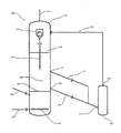
- the illustrated preferred embodiment of a plant 100 comprises a first fluidized bed reactor 101 and a second fluidized bed reactor 102.
- the first fluidized-bed reactor 101 has an inlet 103 in the bottom region, via which hydrogen and gaseous silicon tetrachloride and optionally hydrogen chloride can be introduced into the reactor.
- the manifold 104 Within the reactor 101 is the manifold 104, which makes it possible to produce a uniformly distributed gas flow within the reactor.
- the metallurgical silicon to be reacted can be introduced into the reactor 101 . This forms, caused by the upflowing vapor-gas mixture of hydrogen and silicon tetrachloride or possibly also hydrogen chloride in the reaction chamber 106 of the fluidized bed reactor 101, a fluidized bed.
- the fluidized bed is preferably a stationary fluidized bed, that is to say a fluidized bed which has a relatively clear boundary both upwards and downwards.
- the lower limit is indicated by the mark 107 , the upper limit by the mark 108.
- Between the two markings is the so-called fluid portion of the fluidized bed.
- silicon particles can be discharged from the fluidized-bed reactor 101 via the outlet 109 and transferred via the connecting line 110 and the inlet 111 into the fluidized-bed reactor 102 . Also shown is the outlet 112 and the connecting line 113. By way of this it is possible to remove silicon particles from a higher section of the fluid section of the fluidized bed.
- the reactor 101 can also have more than two such discharge options.
- the discharged silicon particles can in turn form a fluidized bed with hydrogen and silicon tetrachloride and optionally with hydrogen chloride (the fluidized-bed reactor 102 can for this purpose have its own inlet possibilities for hydrogen, silicon tetrachloride and hydrogen chloride).
- the resulting trichlorosilane-containing reaction mixture can be returned via the outlet 114 and the connecting line 115 in the fluidized bed reactor 101.
- the mixture is introduced into the reactor 101 above the upper limit 108 of the fluidized bed. There it can be mixed with the trichlorosilane-containing product mixture formed in the reactor 101 .
- the combined trichlorosilane-containing product mixture can be discharged from the reactor and fed to its further use.
- the particle separator 118 Upstream of the outlet 116 is the particle separator 118. This only passes silicon particles having a certain maximum particle size. The remaining particles are separated within the separator 118 and recycled via the particle case outlet 119 into the fluidized bed.
Landscapes
- Chemical & Material Sciences (AREA)
- Organic Chemistry (AREA)
- Inorganic Chemistry (AREA)
- Chemical Kinetics & Catalysis (AREA)
- Silicon Compounds (AREA)
- Devices And Processes Conducted In The Presence Of Fluids And Solid Particles (AREA)
- Manufacture And Refinement Of Metals (AREA)
- Catalysts (AREA)
- Organic Low-Molecular-Weight Compounds And Preparation Thereof (AREA)
Description
- Gegenstand der vorliegenden Erfindung ist ein Verfahren zur Herstellung von Trichlorsilan durch vorzugsweise katalytische Umsetzung von Siliziumpartikeln mit Tetrachlorsilan und Wasserstoff in einem Wirbelschichtreaktor sowie eine Anlage, in der ein solches Verfahren betrieben werden kann.
- Wie allgemein bekannt ist, ist Trichlorsilan ein wertvolles Zwischenprodukt bei der Herstellung von hochreinem Silizium, wie es für photovoltaische Anwendungen und für die Halbleitertechnik sowie in der Siliziumorganik benötigt wird. So kann beispielsweise metallurgisches Silizium, das häufig noch einen relativ hohen Anteil an Verunreinigungen aufweist, in Trichlorsilan überführt werden, das anschließend mit Wasser zu hochreinem Silizium reduziert wird. Eine derartige Vorgehensweise ist beispielsweise aus der
DE 2 919 086 bekannt. Alternativ dazu kann man hochreines Silizium auch durch thermische Zersetzung von Monosilan gewinnen, wie es z. B. in derDE 33 11 650 beschrieben ist. Das dafür benötigte Monosilan lässt sich wiederum insbesondere durch Disproportionierung von Trichlorsilan erhalten. - Für die Synthese von Trichlorsilan kommen insbesondere zwei Reaktionswege in Frage, nämlich zum einen die direkte Umsetzung von metallurgischem Silizium mit Chlorwasserstoff (Hydrochlorierungsvariante) und zum anderen durch Umsetzung von Siliziumtetrachlorid mit metallurgischem Silizium und Wasserstoff (Hydrierungsvariante).
- Insbesondere die Hydrierungsvariante ist sehr gebräuchlich, da das dafür benötigte Siliziumtetrachlorid bei der Disproportionierung von Trichlorsilan zu Monosilan ohnehin zwingend als Nebenprodukt (wie in praktisch allen Verfahren zur Herstellung von Polysilizium) anfällt. Die Gesamtausbeute der Synthesekette Si + SiCl4 + H2 → SiHCl3 → SiH4 + SiCl4 → Si lässt sich natürlich deutlich erhöhen, indem das bei der Disproportionierung Siliziumtetrachlorid wieder in den Reaktionsweg eingespeist wird.
- Die Umsetzung von Siliziumtetrachlorid mit metallurgischem Silizium und Wasserstoff zu Trichlorsilan erfolgt vorzugsweise in Wirbelschichtreaktoren. Ein geeigneter Wirbelschichtreaktor ist beispielsweise aus der
DE 196 47 162 A1 oder derDE 196 47 154 A1 bekannt. Ein solcher umfasst in der Regel einen Reaktionsraum, in dessen unterem Bereich eine Verteilerplatte vorgesehen ist, über die Wasserstoffgas und dampfförmiges Silizumtetrachlorid in den Reaktionsraum eingeströmt werden können. Siliziumpartikel können über einen geeigneten Einlass direkt in den Reaktionsraum überführt werden. Durch das nach oben strömende Gas-gemisch aus Wasserstoff und dampfförmigem Siliziumtetrachlorid werden die Siliziumpartikel in einen fluidisierten Zustand überführt und bilden eine Wirbelschicht aus. - Das in der Wirbelschicht entstehende Trichlorsilan (sowie gegebenenfalls andere Reaktionsprodukte) wird in der Regel über einen Auslass im oberen Bereich des Wirbelschichtreaktors aus dem Reaktor abgeführt. Problematisch ist dabei, dass insbesondere bei höheren Gasgeschwindigkeiten stets feine Siliziumpartikel aus der Wirbelschicht mitgerissen werden und zusammen mit dem trichlorsilanhaltigen Produktgasstrom aus dem Reaktor entweichen. Damit dieser Schwund nicht überhand nimmt, sind Wirbelschichtreaktoren zur Synthese von Trichlorsilan in der Regel mit Partikelabscheidern wie Zyklonen versehen. Geeignete Zyklone weisen in der Regel einen Zyklonkörper mit einem Gaseinlass, einem Gasauslass, einem Partikel-Fallauslass und einem Partikelabführrohr auf, dessen oberes Ende mit dem Partikel-Fallauslass des Zyklonkörpers kommuniziert. Gewöhnlich ist ein Staubtrichter zwischen dem Zyklonkörper und dem Partikelabführrohr eingesetzt.
- Der Zyklonkörper, der Staubtrichter und das Partikelabführrohr sind in der Regel so im Reaktionsraum des Wirbelschichtreaktors angeordnet, dass sich der Zyklonkörper in einem oberen Teil des Reaktionsraumes, idealerweise über dem im Reaktionsraume gebildeten Wirbelbett, befindet. Ein unterer Teil des Partikelabführrohrs ragt hingegen vorzugsweise bis in die Wirbelschicht hinein.
- In einem typischen Betriebszustand eines solchen Wirbelschichtreaktors liegt der mittlere Partikeldurchmesser der in den Reaktionsraum eingebrachten Siliziumpartikel zwischen ca. 100 und 400 µm. Im laufenden Betrieb reduziert sich die Größe der Partikel allerdings, Partikel mit Größen von z.B. weniger als 10 µm treten dann vermehrt auf. Sobald eine bestimmte Partikelgröße (die genaue Größe hängt von Parametern wie der Dichte der Teilchen, den Strömungsgeschwindigkeiten im Wirbelschichtreaktor etc. ab) unterschritten wird, werden Partikel mit einer solchen Größe mit dem trichlorsilanhaltigen Produktgasstrom mitgerissen und treten in den Zyklonkörper des Zyklons ein. Innerhalb des Zyklonkörpers werden alle Siliziumpartikel über einer bestimmten (in der Regel einstellbaren) Partikelgröße vom Produktgasstrom separiert und fallen durch den Partikel-Fallauslass des Zyklonkörpers in das Partikelabführrohr. Durch dieses können sie direkt ins Wirbelbett rücküberführt werden. Feinere Partikel passieren dagegen den Zyklon und müssen in Folgeschritten durch Filter oder sonstige Mittel aus dem trichlorsilanhaltigen Produktgasstrom aufwendig abgetrennt werden.
- Aus der
WO 02/48024 A2 - Ein weiteres in derartigen Wirbelschichtreaktoren auftretendes Problem ist, dass das partikulär eingeführte metallurgische Silizium stets einen gewissen Anteil an "inaktiven" oder "inerten" Siliziumpartikeln aufweist, die sich unter den im Wirbelschichtreaktor vorherrschenden Reaktionsbedingungen nicht oder nur sehr langsam mit dem gasförmigen Siliziumtetrachlorid und dem Wasserstoff umsetzen lassen. Dies ist beispielsweise der Fall, wenn ein Siliziumpartikel eine stark oxidierte Oberfläche aufweist, die reaktive Teile des Partikels vor dem Dampf-Gas-Gemisch aus Siliziumtetrachlorid und Wasserstoff abschirmt. Im Dauerbetrieb steigt die Konzentration solcher Partikel in der Wirbelschicht mit der Zeit an und kann die Effizienz des betroffenen Wirbelschichtreaktors erheblich beeinflussen. In der Folge kann es erforderlich sein, in regelmäßigen Zeitabständen den Betrieb des Wirbelschichtreaktors zu unterbrechen und die enthaltene Siliziumcharge zum Teil oder komplett auszutauschen.
- Alternativ dazu versuchte man, die Konzentration an inaktiven Partikeln in der Wirbelschicht gering zu halten, indem man über den im Wirbelschichtreaktor angeordneten Partikelabscheider zusammen mit dem Produktgasstrom mehr und auch größere Partikel aus dem Reaktor entweichen lässt, als dies eigentlich erforderlich wäre. Wie bereits erwähnt, lässt sich die Selektivität von Partikelabscheidern wie Zyklonen in der Regel ja variieren.
- In der Folge erhöht sich allerdings der Aufwand bei der sich anschließenden Abtrennung der Partikel vom trichlorsilanhaltigen Produktgasstrom deutlich. Weiterhin sinkt natürlich auch die Gesamtausbeute der Umsetzung im Hinblick auf das eingesetzte metallurgische Silizium deutlich.
- Der vorliegenden Erfindung lag die Aufgabe zugrunde, eine technische Lösung zur Herstellung von Trichlorsilan bereitzustellen, bei der die obigen Probleme nicht auftreten oder zumindest weitestgehend vermieden werden.
- Diese Aufgabe wird gelöst durch das Verfahren zur Herstellung von Trichlorsilan mit den Merkmalen des Anspruchs 1 und die Anlage zur Herstellung von Trichlorsilan mit den Merkmalen des Anspruchs 6. Bevorzugte Ausführungsformen des erfindungsgemäßen Verfahrens sind in den abhängigen Ansprüchen 2 bis 5 angegeben. Bevorzugte Ausführungsformen der erfindungsgemäßen Anlage finden sich in den abhängigen Ansprüchen 7 und 8. Der Wortlaut sämtlicher Ansprüche wird hiermit durch Bezugnahme zum Inhalt dieser Beschreibung gemacht.
- Das erfindungsgemäße Verfahren macht wie die meisten der eingangs genannten gattungsgemäßen Verfahren Gebrauch von einem Wirbelschichtreaktor, in dem Siliziumpartikel mit Tetrachlorsilan und Wasserstoff sowie gegebenfalls mit Chlorwasserstoff zu einem trichlorsilanhaltigen Produktgasstrom umgesetzt werden. Die Anwesenheit von Chlorwasserstoff ist in der Regel nicht zwingend erforderlich, kann sich insbesondere beim Anfahren des Reaktors aber positiv auswirken.
- Der eingesetzte Wirbelschichtreaktor weist mindestens einen Einlass für das Tetrachlorsilan und den Wasserstoff, insbesondere ein Dampf-Gas-Gemisch aus beiden, sowie gegebenfalls den Chlorwasserstoff auf sowie mindestens einen Einlass für die Siliziumpartikel. Zumindest der mindestens eine Einlass für das Tetrachlorsilan und den Wasserstoff ist dabei vorzugsweise im Bodenbereich des Wirbelschichtreaktors angeordnet, so dass das Tetrachlorsilan und der Wasserstoff innerhalb des Wirbelschichtreaktors nach oben strömen können. In den Reaktor eingebrachte Siliziumpartikel können dann mit dem Tetrachlorsilan und dem Wasserstoff eine Wirbelschicht ausbilden.
- In bevorzugten Ausführungsformen des erfindungsgemäßen Verfahrens erfolgt die Umsetzung der Siliziumpartikel mit Tetrachlorsilan und Wasserstoff sowie gegebenenfalls mit Chlorwasserstoff unter katalytischen Bedingungen. Als Katalysatoren kommen insbesondere eisen- und/oder kupferhaltige Katalysatoren in Frage, wobei letztere bevorzugt eingesetzt werden. Als eisenhaltiger Katalysator eignet sich beispielsweise metallisches Eisen, als kupferhaltiger Katalysator metallisches Kupfer (beispielsweise in Form von Kupferpulver oder Kupfer-Flakes) oder eine Kupferverbindung. Der Katalysator kann separat in den Wirbelschichtreaktor eingebracht werden oder vorab mit den Siliziumpartiklen gemischt werden.
- Der verwendete Wirbelschichtreaktor weist weiterhin mindestens einen Auslass für den trichlorsilanhaltigen Produktgasstrom auf. Wie eingangs bereits erwähnt, enthält ein solcher trichlorsilanhaltiger Produktgasstrom in aller Regel stets kleine Siliziumpartikel. Deshalb ist auch beim im Rahmen der vorliegenden Erfindung verwendeten Wirbelschichtreaktor dem mindestens einen Auslass für den trichlorsilanhaltigen Produktgasstrom mindestens ein Partikelabscheider vorgeschaltet, der selektiv nur Siliziumpartikel bis hin zu einer bestimmten Maximalpartikelgröße passieren lässt. Diese Maximalpartikelgröße ist in aller Regel einstellbar, abhängig vom verwendeten Partikelabscheider. So kann als Partikelabscheider beispielsweise ein Fliehkraftabscheider, insbesondere ein Zyklon, verwendet werden. Bei diesen Abscheidern lässt sich in der Regel präzise einstellen, welche Partikel mit welcher Größe abgetrennt werden sollen und welche Partikel den Abscheider noch passieren dürfen.
- Besonders zeichnet sich ein erfindungsgemäßes Verfahren dadurch aus, dass in vorzugsweise regelmäßigen Zeitabständen oder kontinuierlich über mindestens einen weiteren Auslass Siliziumpartikel aus dem Reaktor ausgeschleust werden, wobei diesem mindestens einen weiteren Auslass kein solcher selektiv arbeitender Partikelabscheider vorgeschaltet ist. Entsprechend kann der mindestens eine weitere Auslass auch von Siliziumpartikeln mit Durchmessern jenseits der erwähnten Maximalpartikelgröße passiert werden.
- Wie eingangs erwähnt, tritt in Wirbelschichtreaktoren zur Herstellung von Trichlorsilan häufig das Problem auf, dass sich innerhalb des Reaktors inaktive Siliziumpartikel anreichern und so die Effizienz des Reaktors herabgesetzt wird. Durch das gezielte Ausschleusen von Siliziumpartikeln, die in der Regel über den mindestens einen Einlass für die Siliziumpartikel unverzüglich durch frische Silliziumpartikel ersetzt werden, lässt sich eine solche Anreicherung von inaktiven Partikeln effizient verhindern.
- Besonders bevorzugt werden die Siliziumpartikel unmittelbar dem Fluidabschnitt einer Wirbelschicht im Wirbelschichtreaktor entnommen. Auch bei der vorliegenden Erfindung werden der Wasserstoff und das Tetrachlorsilan sowie gegebenenfalls der Chlorwasserstoff bevorzugt im Bodenbereich des Wirbelschichtreaktors in den Reaktor eingeströmt. Oberhalb dieses Bodenbereiches bildet sich dann die Wirbelschicht aus. Diese weist in der Regel eine deutliche untere Grenze auf. Nach oben hin kann der Fluidabschnitt relativ deutlich begrenzt sein, insbesondere wenn es sich bei der Wirbelschicht um eine stationäre Wirbelschicht handelt. Als Fluidabschnitt einer Wirbelschicht wird dann der Abschnitt zwischen der oberen und der unteren Grenze bezeichnet.
- Handelt es sich bei der Wirbelschicht hingegen um eine zirkulierende Wirbelschicht, so besitzt diese aufgrund der größeren Strömungsgeschwindigkeiten des Wasserstoffs und des Siliziumtetrachlorids sowie gegebenenfalls des Chlorwasserstoffs häufig keine deutliche obere Grenze mehr.
- Die ausgeschleusten Siliziumpartikel werden in besonders bevorzugten Ausführungsformen des erfindungsgemäßen Verfahrens in einen zweiten Reaktor überführt, bei dem es sich besonders bevorzugt um einen zweiten Wirbelschichtreaktor handelt. Dort werden sie wiederum mit Tetrachlorsilan und Wasserstoff sowie gegebenenfalls mit Chlorwasserstoff zu einem trichlorsilanhaltigen Produktgasstrom umgesetzt. Im Gegensatz zu Siliziumpartikeln, die über den Auslass mit dem Partikelabscheider aus dem Reaktor ausgetragen werden, werden die gezielt über den mindestens einen weiteren Auslass ausgeschleusten Partikel somit weiterverwertet. Dies trägt natürlich positiv zur Gesamtausbeute des erfindungsgemäßen Verfahrens bei.
- Der im zweiten Reaktor entstehende trichlorsilanhaltige Produktgasstrom kann grundsätzlich völlig separat von dem im ersten Reaktor entstehenden Produktgasstrom aufgereinigt und weiterverarbeitet werden. Besonders bevorzugt ist es jedoch, wenn der trichlorsilanhaltige Produktgasstrom aus dem zweiten Reaktor in den vorgeschalteten (ersten) Wirbelschichtreaktor rücküberführt wird. Dies ermöglicht es nämlich, den zweiten Reaktor aus baulicher Sicht sehr einfach zu halten. Es werden so nämlich beispielsweise keine separaten Partikelabscheider im zweiten Reaktor benötigt. Stattdessen kann der trichlorsilanhaltige Produktgasstrom aus dem zweiten Reaktor mit dem trichlorsilanhaltigen Produktgasstrom aus dem vorgeschalteten Wirbelschichtreaktor vereinigt werden. Die vereinigten Produktgasströme passieren dann den mindestens einen Partikelabscheider im ersten Wirbelschichtreaktor.
- Damit sich der Anteil an inaktiven Partikeln, der aus dem ersten Wirbelschichtreaktor in den zweiten Reaktor überführt wird, in letzterem auch umsetzen lässt und sich nicht dort anreichert, ist es bevorzugt, dass die Reaktionsbedingungen, bei denen die ausgeschleusten Siliziumpartikel umgesetzt werden, sich im zweiten Reaktor von denen im vorgeschalteten Wirbelschichtreaktor unterscheiden. Dies gilt insbesondere im Hinblick auf die Reaktionsparameter Temperatur und/oder Druck. Besonders bevorzugt wird der zweite Reaktor bei höheren Temperaturen betrieben als der erste Reaktor.
- Theoretisch ist es im übrigen denkbar, dem zweiten Reaktor noch einen parallelen dritten Reaktor sowie gegebenfalls noch weitere Reaktoren nachzuschalten, um wiederum einer Anreicherung von inaktiven Partikeln im zweiten Reaktor vorzubeugen. In der Praxis dürfte dies jedoch in den meisten Fällen nicht erforderlich sein.
- Eine erfindungsgemäße Anlage zur Herstellung von Trichlorsilan weist einen ersten und einen zweiten Reaktor, insbesondere zwei Wirbelschichtreaktoren, auf, die sich jeweils zur Umsetzung von Siliziumpartikeln mit Tetrachlorsilan und Wasserstoff sowie gegebenenfalls mit Chlorwasserstoff zu einem trichlorsilanhaltigen Produktgasstrom eignen. Im ersten Reaktor wird ein erster trichlorsilanhaltiger Produktgasstrom gebildet, im zweiten Reaktor ein zweiter trichlorsilanhaltiger Produktgasstrom.
- Der erste Reaktor weist bevorzugt zumindest die folgenden Komponenten auf:
- mindestens einen Einlass für das Tetrachlorsilan und den Wasserstoff sowie gegebenenfalls den Chlorwasserstoff,
- mindestens einen Einlass für die Siliziumpartikel,
- einen Reaktionsraum, in dem die Siliziumpartikel mit dem Tetrachlorsilan und dem Wasserstoff sowie gegebenenfalls dem Chlorwasserstoff eine Wirbelschicht ausbilden können,
- mindestens einen Auslass für den ersten trichlorsilanhaltigen Produktgasstrom, dem mindestens ein Partikelabscheider vorgeschaltet ist, der selektiv nur Siliziumpartikel bis hin zu einer bestimmten Maximalpartikelgröße passieren lässt und
- mindestens einen weiteren Auslass ohne einen solchen Partikelabscheider, über den auch Siliziumpartikel mit Größen über der Maximalpartikelgröße aus dem Reaktor ausgeschleust werden können.
- Der zweite Reaktor umfasst zumindest
- mindestens einen Einlass für Siliziumpartikel,
- einen Reaktionsraum, in dem die Siliziumpartikel mit Tetrachlorsilan und Wasserstoff sowie gegebenenfalls mit Chlorwasserstoff eine Wirbelschicht ausbilden können und
- mindestens einen Auslass für den zweiten trichlorsilanhaltigen Produktgasstrom.
- Die erfindungsgemäße Anlage zeichnet sich besonders dadurch aus, dass zwischen dem mindestens einen weiteren Auslass des ersten Reaktors und dem mindestens einen Einlass für Siliziumpartikel des zweiten Reaktors eine Verbindung besteht, über die die aus dem ersten Reaktor ausgeschleuste Siliziumpartikel in den zweiten Reaktor überführt werden können. Bei einer solchen Verbindung kann es sich beispielsweise um eine Rohrleitung handeln, die über ein geeignetes Verbindungsstück wie ein Ventil oder eine Klappe an den Einlass bzw. an den Auslass des jeweiligen Reaktors gekoppelt ist.
- Bei dem mindestens einen Partikelabscheider, der vom ersten Wirbelschichtreaktor umfasst ist, handelt es sich bevorzugt um einen oder mehrere Zyklone. Geeignete Zyklone sind dem Fachmann grundsätzlich bekannt und müssen im Rahmen der vorliegenden Erfindung nicht ausführlich erläutert werden. Darüber hinaus kann diesbezüglich auch auf die eingangs gemachten Ausführungen zu geeigneten Zyklonen für Wirbelschichtreaktoren Bezug genommen werden.
- In besonders bevorzugten Ausführungsformen besteht zwischen dem ersten und dem zweiten Reaktor neben der bereits erwähnten Verbindung mindestens eine weitere Verbindung, über die der zweite trichlorsilanhaltige Produktgasstrom in den ersten Reaktor geleitet werden kann. In einer Ausführungsform mit diesen beiden Verbindungen ist der Reaktionsraum des zweiten Reaktors somit dem Reaktionsraum des ersten Reaktors "parallel geschaltet". Das aus dem ersten Reaktor ausgeschleuste Silizium wird im Reaktionsraum des zweiten Reaktors mit Siliziumtetrachlorid und Wasserstoff sowie gegebenefalls mit Chlorwasserstoff umgesetzt, das dabei entstehende Trichlorsilan wird dann wieder in den ersten Reaktor überführt, womit der Kreislauf geschlossen ist.
- Weitere Merkmale der Erfindung ergeben sich aus der nachfolgenden Beschreibung einer bevorzugten Ausführungsform der erfindungsgemäßen Anlage in Verbindung mit den Unteransprüchen. Hierbei können einzelne Merkmale jeweils für sich oder zu mehreren in Kombination miteinander bei einer Ausführungsform der Erfindung verwirklicht sein. Die beschriebenen bevorzugten Ausführungsformen dienen lediglich zur Erläuterung und zum besseren Verständnis der Erfindung und sind in keiner Weise einschränkend zu verstehen.
-
- Fig. 1 zeigt schematisch den Aufbau einer bevorzugten Ausführungsform einer erfindungsgemäßen Anlage mit einem ersten Wirbelschichtreaktor und einem zweiten Wirbelschichtreaktor.
- Die dargestellte bevorzugte Ausführungsform einer erfindungsgemäßen Anlage 100 umfaßt einen ersten Wirbelschichtreaktor 101 und einen zweiten Wirbelschichtreaktor 102.
- Der erste Wirbelschichtreaktor 101 weist im Bodenbereich einen Einlass 103 auf, über den Wasserstoff und gasförmiges Siliziumtetrachlorid sowie gegebenenfalls Chlorwasserstoff in den Reaktor eingeleitet werden kann. Innerhalb des Reaktors 101 befindet sich der Verteiler 104, der es ermöglicht, einen gleichmäßig verteilten Gasstrom innerhalb des Reaktors zu erzeugen. Über den Einlass 105 kann das umzusetzende metallurgische Silizium in den Reaktor 101 eingeführt werden. Dieses bildet, verursacht durch das aufströmende Dampf-Gas-Gemisch aus Wasserstoff und Siliziumtetrachlorid bzw. ggf. auch Chlorwasserstoff im Reaktionsraum 106 des Wirbelschichtreaktors 101 eine Wirbelschicht aus. Bei der Wirbelschicht handelt es sich bevorzugt um eine stationäre Wirbelschicht, also eine Wirbelschicht, die sowohl nach oben als auch nach unten eine relativ deutliche Grenze aufweist. Die untere Begrenzung ist durch die Markierung 107 angedeutet, die obere Begrenzung durch die Markierung 108. Zwischen den beiden Markierungen befindet sich der sogenannte Fluidabschnitt der Wirbelschicht. Aus diesem können über den Auslass 109 Siliziumpartikel aus dem Wirbelschichtreaktor 101 ausgeschleust werden und über die Verbindungsleitung 110 und den Einlass 111 in den Wirbelschichtreaktor 102 überführt werden. Dargestellt ist des weiteren noch der Auslass 112 sowie die Verbindungsleitung 113. Über diese ist es möglich, der Wirbelschicht Siliziumpartikel aus einem höher gelegenen Abschnitt des Fluidabschnitts zu entnehmen. Grundsätzlich kann der Reaktor 101 auch mehr als zwei solcher Ausschleusungsmöglichkeiten aufweisen.
- Im Wirbelschichtreaktor 102 können die ausgeschleusten Siliziumpartikel wiederum mit Wasserstoff und Siliziumtetrachlorid sowie gegebenenfalls mit Chlorwasserstoff eine Wirbelschicht bilden (der Wirbelschichtreaktor 102 kann zu diesem Zweck eigene Einlassmöglichkeiten für Wasserstoff, Siliziumtetrachlorid und Chlorwasserstoff aufweisen). Das dabei entstehende trichlorsilanhaltige Reaktionsgemisch kann über den Auslass 114 und die Verbindungsleitung 115 in den Wirbelschichtreaktor 101 rücküberführt werden. Vorzugsweise wird das Gemisch oberhalb der Obergrenze 108 der Wirbelschicht in den Reaktor 101 eingeleitet. Dort kann es sich mit dem im Reaktor 101 entstehenden trichlorsilanhaltigen Produktgemisch vermischen.
- Über den Auslass 116 und die Ableitung 117 kann das vereinigte trichlorsilanhaltige Produktgemisch aus dem Reaktor abgeleitet und seiner weiteren Verwendung zugeführt werden. Dem Auslass 116 vorgeschaltet ist der Partikelabscheider 118. Dieser lässt lediglich Siliziumpartikel mit einer bestimmten Maximalpartikelgröße passieren. Die übrigen Partikel werden innerhalb des Abscheiders 118 abgetrennt und über den Partikel-Fallauslass 119 in die Wirbelschicht rückgeführt.
Claims (8)
- Verfahren zur Herstellung von Trichlorsilan, bei dem Siliziumpartikel mit Tetrachlorsilan und Wasserstoff und gegebenenfalls mit Chlorwasserstoff in einem Wirbelschichtreaktor (101) zu einem trichlorsilanhaltigen Produktgasstrom umgesetzt werden, der Wirbelschichtreaktor (101) mit mindestens einem Einlass (103) für das Tetrachlorsilan und den Wasserstoff sowie gegebenfalls den Chlorwasserstoff, mindestens einem Einlass (105) für die Siliziumpartikel, die mit dem Tetrachlorsilan und dem Wasserstoff eine Wirbelschicht ausbilden, und mindestens einem Auslass (117) für den trichlorsilanhaltigen Produktgasstrom, dem mindestens ein Partikelabscheider (118) vorgeschaltet ist, der selektiv nur Siliziumpartikel bis hin zu einer bestimmten Maximalpartikelgröße passieren lässt, dadurch gekennzeichnet, dass in vorzugsweise regelmäßigen Zeitabständen oder kontinuierlich über mindestens einen weiteren Auslass (109; 112) ohne einen solchen Partikelabscheider (118) Siliziumpartikel aus dem Reaktor (101) ausgeschleust werden.
- Verfahren nach Anspruch 1, dadurch gekennzeichnet, dass die Siliziumpartikel unmittelbar dem Fluidabschnitt der Wirbelschicht entnommen werden.
- Verfahren nach einem der Ansprüche 1 oder 2, dadurch gekennzeichnet, dass die ausgeschleusten Siliziumpartikel in einen zweiten Reaktor (102), insbesondere in einen zweiten Wirbelschichtreaktor, überführt werden, wo sie mit Tetrachlorsilan und Wasserstoff und gegebenenfalls mit Chlorwasserstoff zu einem zweiten trichlorsilanhaltigen Produktgasstrom umgesetzt werden.
- Verfahren nach Anspruch 3, dadurch gekennzeichnet, dass der zweite trichlorsilanhaltige Produktgasstrom in den vorgeschalteten Wirbelschichtreaktor (101) mit dem mindestens einen weiteren Auslass ohne Partikelabscheider (109; 112) überführt wird.
- Verfahren nach einem der Ansprüche 2 bis 4, dadurch gekennzeichnet, dass sich die Reaktionsbedingungen im zweiten Reaktor (102), insbesondere Temperatur und/oder Druck, bei denen die ausgeschleusten Siliziumpartikel umgesetzt werden, von denen im vorgeschalteten Wirbelschichtreaktor (101) mit dem mindestens einen weiteren Auslass ohne Partikelabscheider (109; 112) unterscheiden.
- Anlage (100) zur Herstellung von Trichlorsilan, insbesondere zur Durchführung eines Verfahrens nach einem der vorhergehenden Ansprüche, umfassend einen ersten als Wirbelschichtreaktor ausgebildeten Reaktor (101) zur Umsetzung von Siliziumpartikeln mit Tetrachlorsilan und Wasserstoff und gegebenenfalls mit Chlorwasserstoff zu einem ersten trichlorsilanhaltigen Produktgasstrom und einen zweiten, insbesondere als Wirbelschichtreaktor ausgebildeten Reaktor (102) zur Umsetzung von Siliziumpartikeln mit Tetrachlorsilan und Wasserstoff und gegebenenfalls mit Chlorwasserstoff zu einem zweiten trichlorsilanhaltigen Produktgasstrom, der erste Reaktor (101) mit• mindestens einem Einlass (103) für das Tetrachlorsilan und den Wasserstoff sowie gegebenenfalls den Chlorwasserstoff,• mindestens einem Einlass (105) für die Siliziumpartikel,• einem Reaktionsraum (106), in dem die Siliziumpartikel mit dem Tetrachlorsilan und dem Wasserstoff eine Wirbelschicht ausbilden können,• mindestens einem Auslass (117) für den ersten trichlorsilanhaltigen Produktgasstrom, dem mindestens ein Partikelab scheider (118) vorgeschaltet ist, der selektiv nur Siliziumpartikel bis hin zu einer bestimmten Maximalpartikelgröße passieren lässt und• mindestens einem weiteren Auslass (109; 112) ohne einen solchen Partikelabscheider, über den auch Siliziumpartikel mit Größen über der Maximalpartikelgröße aus dem Reaktor (101) ausgeschleust werden können,
der zweite Reaktor (102) mit• mindestens einem Einlass (111) für Siliziumpartikel,• einem Reaktionsraum, in dem die Siliziumpartikel mit Tetrachlorsilan und Wasserstoff eine Wirbelschicht ausbilden können und• mindestens einem Auslass (114) für den zweiten trichlorsilanhaltigen Produktgasstrom,wobei zwischen dem mindestens einen weiteren Auslass (109; 112) des ersten Reaktors (101) und dem mindestens einen Einlass (111) für Siliziumpartikel des zweiten Reaktors (102) eine Verbindung (110) besteht, über die die aus dem ersten Reaktor (101) ausgeschleusten Siliziumpartikel in den zweiten Reaktor (102) überführt werden können. - Anlage nach Anspruch 6, dadurch gekennzeichnet, dass es sich bei dem mindestens einen Partikelabscheider (118) um einen oder mehrere Zyklone handelt.
- Anlage nach Anspruch 6 oder 7, dadurch gekennzeichnet, dass zwischen dem ersten (101) und dem zweiten Reaktor (102) mindestens eine weitere Verbindung (115) besteht, über die der zweite trichlorsilanhaltige Produktgasstrom in den ersten Reaktor (101) geleitet werden kann.
Applications Claiming Priority (2)
| Application Number | Priority Date | Filing Date | Title |
|---|---|---|---|
| DE102009037155A DE102009037155B3 (de) | 2009-08-04 | 2009-08-04 | Verfahren und Anlage zur Herstellung von Trichlorsilan |
| PCT/EP2010/061224 WO2011015560A1 (de) | 2009-08-04 | 2010-08-02 | Verfahren und anlage zur herstellung von trichlorsilan |
Publications (2)
| Publication Number | Publication Date |
|---|---|
| EP2462058A1 EP2462058A1 (de) | 2012-06-13 |
| EP2462058B1 true EP2462058B1 (de) | 2014-01-01 |
Family
ID=42813912
Family Applications (1)
| Application Number | Title | Priority Date | Filing Date |
|---|---|---|---|
| EP10739921.4A Active EP2462058B1 (de) | 2009-08-04 | 2010-08-02 | Verfahren und anlage zur herstellung von trichlorsilan |
Country Status (11)
| Country | Link |
|---|---|
| US (1) | US20120189526A1 (de) |
| EP (1) | EP2462058B1 (de) |
| JP (1) | JP5788877B2 (de) |
| KR (1) | KR20120041234A (de) |
| CN (1) | CN102639440B (de) |
| CA (1) | CA2769759A1 (de) |
| DE (1) | DE102009037155B3 (de) |
| MY (1) | MY162486A (de) |
| RU (1) | RU2547269C2 (de) |
| TW (1) | TWI507359B (de) |
| WO (1) | WO2011015560A1 (de) |
Families Citing this family (16)
| Publication number | Priority date | Publication date | Assignee | Title |
|---|---|---|---|---|
| DE102010044108A1 (de) * | 2010-11-18 | 2012-05-24 | Evonik Degussa Gmbh | Herstellung von Chlorsilanen aus kleinstteiligem Reinstsilicium |
| EP2749534B1 (de) * | 2011-10-18 | 2018-12-19 | Toagosei Co., Ltd. | Verfahren zur herstellung von chloropolysilan und fliessbettreaktor |
| DE102012224182A1 (de) | 2012-12-21 | 2014-07-10 | Evonik Degussa Gmbh | Verfahren zur Aufbereitung feinteiliger Feststoffe bei der Herstellung von Chlorsilanen |
| DE102013201742A1 (de) | 2012-12-21 | 2014-06-26 | Evonik Industries Ag | Verfahren zur Aufbereitung von Silizium-haltigem feinkörnigen Material bei der Herstellung von Chlorsilanen |
| US20160008784A1 (en) * | 2013-03-13 | 2016-01-14 | Sitec Gmbh | Temperature management in chlorination processes and systems related thereto |
| DE102013212908A1 (de) | 2013-07-02 | 2015-01-08 | Wacker Chemie Ag | Analyse der Zusammensetzung eines Gases oder eines Gasstromes in einem chemischen Reaktor und ein Verfahren zur Herstellung von Chlorsilanen in einem Wirbelschichtreaktor |
| JP6037047B2 (ja) * | 2013-09-30 | 2016-11-30 | エルジー・ケム・リミテッド | 卜リクロロシラン製造方法 |
| WO2015089214A1 (en) * | 2013-12-10 | 2015-06-18 | Summit Process Design, Inc. | Process for producing trichlorosilane |
| EP3088358A1 (de) | 2015-04-28 | 2016-11-02 | Evonik Degussa GmbH | Verfahren zur aufbereitung feinteiliger feststoffe bei der herstellung von chlorsilanen |
| EP3100979A1 (de) | 2015-06-02 | 2016-12-07 | Evonik Degussa GmbH | Aufbereitung feinteiliger feststoffe bei der herstellung von chlorsilanen durch sintern bei niedrigen temperaturen |
| EP3100978A1 (de) | 2015-06-02 | 2016-12-07 | Evonik Degussa GmbH | Aufbereitung feinteiliger feststoffe bei der herstellung von chlorsilanen durch agglomerieren und kompaktierung |
| KR101987129B1 (ko) * | 2016-09-19 | 2019-06-10 | 한화케미칼 주식회사 | 3염화 실란 합성용 유동층 반응기 |
| CN107433055B (zh) * | 2017-08-30 | 2019-10-08 | 上海华畅环保设备发展有限公司 | 沸腾床分离器中沸腾颗粒再生方法及装置 |
| CN109395675B (zh) * | 2018-09-14 | 2021-07-20 | 四川永祥多晶硅有限公司 | 一种固定流化工艺 |
| EP3962861A1 (de) * | 2019-04-29 | 2022-03-09 | Wacker Chemie AG | Verfahren zur herstellung von trichlorsilan mit struktur-optimierten silicium-partikeln |
| CN116639699B (zh) * | 2023-07-12 | 2024-02-02 | 江苏中圣高科技产业有限公司 | 一种制备三氯氢硅的生产工艺及系统 |
Family Cites Families (21)
| Publication number | Priority date | Publication date | Assignee | Title |
|---|---|---|---|---|
| GB2028289B (en) * | 1978-08-18 | 1982-09-02 | Schumacher Co J C | Producing silicon |
| US4676967A (en) * | 1978-08-23 | 1987-06-30 | Union Carbide Corporation | High purity silane and silicon production |
| DE3024319C2 (de) * | 1980-06-27 | 1983-07-21 | Wacker-Chemitronic Gesellschaft für Elektronik-Grundstoffe mbH, 8263 Burghausen | Kontinuierliches Verfahren zur Herstellung von Trichlorsilan |
| JPS57118017A (en) * | 1981-01-16 | 1982-07-22 | Koujiyundo Silicon Kk | Manufacture of trichlorosilane |
| JPS57156318A (en) * | 1981-03-16 | 1982-09-27 | Koujiyundo Silicon Kk | Production of trichlorosilane |
| FR2530638A1 (fr) * | 1982-07-26 | 1984-01-27 | Rhone Poulenc Spec Chim | Procede de preparation d'un melange a base de trichlorosilane utilisable pour la preparation de silicium de haute purete |
| FR2533906A1 (fr) * | 1982-09-30 | 1984-04-06 | Rhone Poulenc Spec Chim | Procede et dispositif pour la preparation de silane pur par reaction de chlorosilanes avec l'hydrure de lithium |
| US4526769A (en) * | 1983-07-18 | 1985-07-02 | Motorola, Inc. | Trichlorosilane production process |
| CN85107465A (zh) * | 1985-10-12 | 1987-04-15 | 北京有色冶金设计研究总院 | 四氯化硅氢化新工艺 |
| JP2519094B2 (ja) * | 1988-11-29 | 1996-07-31 | 高純度シリコン株式会社 | トリクロロシラン製造用流動反応装置 |
| JP3778631B2 (ja) * | 1995-11-14 | 2006-05-24 | 株式会社トクヤマ | サイクロン及びこれを備えた流動層反応装置 |
| US5776416A (en) * | 1995-11-14 | 1998-07-07 | Tokuyama Corporation | Cyclone and fluidized bed reactor having same |
| JP3708649B2 (ja) * | 1995-12-25 | 2005-10-19 | 株式会社トクヤマ | 銅シリサイドを有する金属珪素粒子の製造方法 |
| JP3708648B2 (ja) * | 1995-12-25 | 2005-10-19 | 株式会社トクヤマ | トリクロロシランの製造方法 |
| DE19654154A1 (de) * | 1995-12-25 | 1997-06-26 | Tokuyama Corp | Verfahren zur Herstellung von Trichlorsilan |
| DE10062413A1 (de) * | 2000-12-14 | 2002-07-04 | Solarworld Ag | Verfahren zur Herstellung von Trichlorsilan |
| RU2274602C1 (ru) * | 2004-08-16 | 2006-04-20 | Федеральное государственное унитарное предприятие "Государственный научно-исследовательский и проектный институт редкометаллической промышленности "Гиредмет" | Способ получения трихлорсилана |
| DE102004045245B4 (de) * | 2004-09-17 | 2007-11-15 | Degussa Gmbh | Vorrichtung und Verfahren zur Herstellung von Silanen |
| JP5397580B2 (ja) * | 2007-05-25 | 2014-01-22 | 三菱マテリアル株式会社 | トリクロロシランの製造方法と製造装置および多結晶シリコンの製造方法 |
| CN101125654A (zh) * | 2007-09-04 | 2008-02-20 | 浙江开化合成材料有限公司 | 一种用于三氯氢硅生产的大型流化床反应器 |
| CN101279735A (zh) * | 2008-05-30 | 2008-10-08 | 中蓝晨光化工研究院有限公司 | 三氯氢硅的生产方法及其设备 |
-
2009
- 2009-08-04 DE DE102009037155A patent/DE102009037155B3/de active Active
-
2010
- 2010-08-02 CN CN201080043459.XA patent/CN102639440B/zh active Active
- 2010-08-02 EP EP10739921.4A patent/EP2462058B1/de active Active
- 2010-08-02 US US13/388,692 patent/US20120189526A1/en not_active Abandoned
- 2010-08-02 JP JP2012523311A patent/JP5788877B2/ja not_active Expired - Fee Related
- 2010-08-02 CA CA2769759A patent/CA2769759A1/en not_active Abandoned
- 2010-08-02 WO PCT/EP2010/061224 patent/WO2011015560A1/de not_active Ceased
- 2010-08-02 KR KR1020127005460A patent/KR20120041234A/ko not_active Withdrawn
- 2010-08-02 MY MYPI2012000491A patent/MY162486A/en unknown
- 2010-08-02 RU RU2012106750/04A patent/RU2547269C2/ru active
- 2010-08-04 TW TW099125977A patent/TWI507359B/zh not_active IP Right Cessation
Also Published As
| Publication number | Publication date |
|---|---|
| EP2462058A1 (de) | 2012-06-13 |
| MY162486A (en) | 2017-06-15 |
| JP5788877B2 (ja) | 2015-10-07 |
| CA2769759A1 (en) | 2011-02-10 |
| RU2012106750A (ru) | 2013-09-10 |
| KR20120041234A (ko) | 2012-04-30 |
| CN102639440B (zh) | 2017-05-31 |
| TW201111281A (en) | 2011-04-01 |
| WO2011015560A1 (de) | 2011-02-10 |
| TWI507359B (zh) | 2015-11-11 |
| DE102009037155B3 (de) | 2010-11-04 |
| CN102639440A (zh) | 2012-08-15 |
| US20120189526A1 (en) | 2012-07-26 |
| JP2013500928A (ja) | 2013-01-10 |
| RU2547269C2 (ru) | 2015-04-10 |
Similar Documents
| Publication | Publication Date | Title |
|---|---|---|
| EP2462058B1 (de) | Verfahren und anlage zur herstellung von trichlorsilan | |
| EP1754539B1 (de) | Wirbelschicht-Strahlmühle und Verfahren zum Zerkleinern von Silicium | |
| EP2265546B1 (de) | Verfahren und anlage zur herstellung von reinstsilizium | |
| AT405723B (de) | Verfahren zur herstellung feinteiliger metall- und keramikpulver | |
| EP2997175B1 (de) | Reaktor zur herstellung von polykristallinem silicium und verfahren zur entfernung eines silicium enthaltenden belags auf einem bauteil eines solchen reaktors | |
| DE10260737B4 (de) | Verfahren und Anlage zur Wärmebehandlung von titanhaltigen Feststoffen | |
| DE19654154A1 (de) | Verfahren zur Herstellung von Trichlorsilan | |
| EP1390296A1 (de) | Verfahren zur herstellung von hochreinem, granularem silizium in einer wirbelschicht | |
| EP2364271B1 (de) | Verfahren und vorrichtung zur herstellung von reinstsilzium | |
| DE19647162B4 (de) | Zyklon und Wirbelschichtreaktor | |
| DE10260735B4 (de) | Verfahren und Anlage zur Wärmebehandlung von sulfidischen Erzen | |
| EP2315621A1 (de) | Verfahren sowie eine anlage zur reduktion von stickoxiden staubhaltiger abgase mittels eines scr-katalysators | |
| WO2011003949A1 (de) | Verfahren und anlage zur herstellung von monosilan | |
| EP2077989B1 (de) | Verfahren zur herstellung von 2,2'-aminoethoxyethanol in elektro-qualität | |
| EP2019084A2 (de) | Verfahren und Reaktor zur Herstellung von Silizium | |
| WO2010037473A1 (de) | Verfahren und vorrichtung für die reinigung von sio2-körnung | |
| DE102009016014B3 (de) | Verfahren zur Gewinnung von reinem Silizium | |
| EP2106519B1 (de) | Vorrichtung und verfahren zur durchführung chemischer und/oder physikalischer reaktionen zwischen einem feststoff und einem gas sowie anlage zur zementherstellung | |
| WO2016184638A1 (de) | Verfahren und anlage zur zersetzung von monosilan | |
| EP3585513B1 (de) | Verfahren und vorrichtung zur hydrolyse einer verbindung | |
| DE102005043435B4 (de) | Verfahren und Vorrichtung zur Reinigung von Wasser mittels Magnetseparation | |
| DE1929426C3 (de) | Verfahren zum Abtrennen von unpolymerisiertem Trioxan aus einer Mischung von Trioxan und Polyoxymethylen | |
| EP1360162B1 (de) | Herstellung von 1,2-dichlorethan | |
| DE102019209898A1 (de) | Vorrichtung und Verfahren zur Bildung von flüssigem Silizium | |
| WO2017032713A1 (de) | Sinterfilter aus polykristallinem silicium |
Legal Events
| Date | Code | Title | Description |
|---|---|---|---|
| PUAI | Public reference made under article 153(3) epc to a published international application that has entered the european phase |
Free format text: ORIGINAL CODE: 0009012 |
|
| 17P | Request for examination filed |
Effective date: 20120229 |
|
| AK | Designated contracting states |
Kind code of ref document: A1 Designated state(s): AL AT BE BG CH CY CZ DE DK EE ES FI FR GB GR HR HU IE IS IT LI LT LU LV MC MK MT NL NO PL PT RO SE SI SK SM TR |
|
| DAX | Request for extension of the european patent (deleted) | ||
| GRAP | Despatch of communication of intention to grant a patent |
Free format text: ORIGINAL CODE: EPIDOSNIGR1 |
|
| INTG | Intention to grant announced |
Effective date: 20130814 |
|
| GRAS | Grant fee paid |
Free format text: ORIGINAL CODE: EPIDOSNIGR3 |
|
| GRAA | (expected) grant |
Free format text: ORIGINAL CODE: 0009210 |
|
| AK | Designated contracting states |
Kind code of ref document: B1 Designated state(s): AL AT BE BG CH CY CZ DE DK EE ES FI FR GB GR HR HU IE IS IT LI LT LU LV MC MK MT NL NO PL PT RO SE SI SK SM TR |
|
| REG | Reference to a national code |
Ref country code: GB Ref legal event code: FG4D Free format text: NOT ENGLISH |
|
| REG | Reference to a national code |
Ref country code: CH Ref legal event code: EP |
|
| REG | Reference to a national code |
Ref country code: IE Ref legal event code: FG4D Free format text: LANGUAGE OF EP DOCUMENT: GERMAN |
|
| REG | Reference to a national code |
Ref country code: DE Ref legal event code: R096 Ref document number: 502010005841 Country of ref document: DE Effective date: 20140213 |
|
| REG | Reference to a national code |
Ref country code: AT Ref legal event code: REF Ref document number: 647514 Country of ref document: AT Kind code of ref document: T Effective date: 20140215 |
|
| REG | Reference to a national code |
Ref country code: NL Ref legal event code: VDEP Effective date: 20140101 |
|
| REG | Reference to a national code |
Ref country code: LT Ref legal event code: MG4D |
|
| PG25 | Lapsed in a contracting state [announced via postgrant information from national office to epo] |
Ref country code: IS Free format text: LAPSE BECAUSE OF FAILURE TO SUBMIT A TRANSLATION OF THE DESCRIPTION OR TO PAY THE FEE WITHIN THE PRESCRIBED TIME-LIMIT Effective date: 20140501 Ref country code: LT Free format text: LAPSE BECAUSE OF FAILURE TO SUBMIT A TRANSLATION OF THE DESCRIPTION OR TO PAY THE FEE WITHIN THE PRESCRIBED TIME-LIMIT Effective date: 20140101 |
|
| PG25 | Lapsed in a contracting state [announced via postgrant information from national office to epo] |
Ref country code: ES Free format text: LAPSE BECAUSE OF FAILURE TO SUBMIT A TRANSLATION OF THE DESCRIPTION OR TO PAY THE FEE WITHIN THE PRESCRIBED TIME-LIMIT Effective date: 20140101 Ref country code: PT Free format text: LAPSE BECAUSE OF FAILURE TO SUBMIT A TRANSLATION OF THE DESCRIPTION OR TO PAY THE FEE WITHIN THE PRESCRIBED TIME-LIMIT Effective date: 20140502 Ref country code: NL Free format text: LAPSE BECAUSE OF FAILURE TO SUBMIT A TRANSLATION OF THE DESCRIPTION OR TO PAY THE FEE WITHIN THE PRESCRIBED TIME-LIMIT Effective date: 20140101 Ref country code: CY Free format text: LAPSE BECAUSE OF FAILURE TO SUBMIT A TRANSLATION OF THE DESCRIPTION OR TO PAY THE FEE WITHIN THE PRESCRIBED TIME-LIMIT Effective date: 20140101 Ref country code: FI Free format text: LAPSE BECAUSE OF FAILURE TO SUBMIT A TRANSLATION OF THE DESCRIPTION OR TO PAY THE FEE WITHIN THE PRESCRIBED TIME-LIMIT Effective date: 20140101 Ref country code: SE Free format text: LAPSE BECAUSE OF FAILURE TO SUBMIT A TRANSLATION OF THE DESCRIPTION OR TO PAY THE FEE WITHIN THE PRESCRIBED TIME-LIMIT Effective date: 20140101 |
|
| REG | Reference to a national code |
Ref country code: DE Ref legal event code: R026 Ref document number: 502010005841 Country of ref document: DE |
|
| PG25 | Lapsed in a contracting state [announced via postgrant information from national office to epo] |
Ref country code: LV Free format text: LAPSE BECAUSE OF FAILURE TO SUBMIT A TRANSLATION OF THE DESCRIPTION OR TO PAY THE FEE WITHIN THE PRESCRIBED TIME-LIMIT Effective date: 20140101 Ref country code: HR Free format text: LAPSE BECAUSE OF FAILURE TO SUBMIT A TRANSLATION OF THE DESCRIPTION OR TO PAY THE FEE WITHIN THE PRESCRIBED TIME-LIMIT Effective date: 20140101 |
|
| PLBI | Opposition filed |
Free format text: ORIGINAL CODE: 0009260 |
|
| PG25 | Lapsed in a contracting state [announced via postgrant information from national office to epo] |
Ref country code: DK Free format text: LAPSE BECAUSE OF FAILURE TO SUBMIT A TRANSLATION OF THE DESCRIPTION OR TO PAY THE FEE WITHIN THE PRESCRIBED TIME-LIMIT Effective date: 20140101 Ref country code: RO Free format text: LAPSE BECAUSE OF FAILURE TO SUBMIT A TRANSLATION OF THE DESCRIPTION OR TO PAY THE FEE WITHIN THE PRESCRIBED TIME-LIMIT Effective date: 20140101 Ref country code: EE Free format text: LAPSE BECAUSE OF FAILURE TO SUBMIT A TRANSLATION OF THE DESCRIPTION OR TO PAY THE FEE WITHIN THE PRESCRIBED TIME-LIMIT Effective date: 20140101 Ref country code: CZ Free format text: LAPSE BECAUSE OF FAILURE TO SUBMIT A TRANSLATION OF THE DESCRIPTION OR TO PAY THE FEE WITHIN THE PRESCRIBED TIME-LIMIT Effective date: 20140101 |
|
| 26 | Opposition filed |
Opponent name: EVONIK DEGUSSA GMBH Effective date: 20140929 |
|
| PLAX | Notice of opposition and request to file observation + time limit sent |
Free format text: ORIGINAL CODE: EPIDOSNOBS2 |
|
| PG25 | Lapsed in a contracting state [announced via postgrant information from national office to epo] |
Ref country code: PL Free format text: LAPSE BECAUSE OF FAILURE TO SUBMIT A TRANSLATION OF THE DESCRIPTION OR TO PAY THE FEE WITHIN THE PRESCRIBED TIME-LIMIT Effective date: 20140101 Ref country code: SK Free format text: LAPSE BECAUSE OF FAILURE TO SUBMIT A TRANSLATION OF THE DESCRIPTION OR TO PAY THE FEE WITHIN THE PRESCRIBED TIME-LIMIT Effective date: 20140101 |
|
| REG | Reference to a national code |
Ref country code: DE Ref legal event code: R026 Ref document number: 502010005841 Country of ref document: DE Effective date: 20140929 |
|
| PLAF | Information modified related to communication of a notice of opposition and request to file observations + time limit |
Free format text: ORIGINAL CODE: EPIDOSCOBS2 |
|
| PG25 | Lapsed in a contracting state [announced via postgrant information from national office to epo] |
Ref country code: MC Free format text: LAPSE BECAUSE OF FAILURE TO SUBMIT A TRANSLATION OF THE DESCRIPTION OR TO PAY THE FEE WITHIN THE PRESCRIBED TIME-LIMIT Effective date: 20140101 Ref country code: LU Free format text: LAPSE BECAUSE OF FAILURE TO SUBMIT A TRANSLATION OF THE DESCRIPTION OR TO PAY THE FEE WITHIN THE PRESCRIBED TIME-LIMIT Effective date: 20140802 |
|
| REG | Reference to a national code |
Ref country code: CH Ref legal event code: PL |
|
| PLBB | Reply of patent proprietor to notice(s) of opposition received |
Free format text: ORIGINAL CODE: EPIDOSNOBS3 |
|
| GBPC | Gb: european patent ceased through non-payment of renewal fee |
Effective date: 20140802 |
|
| PG25 | Lapsed in a contracting state [announced via postgrant information from national office to epo] |
Ref country code: LI Free format text: LAPSE BECAUSE OF NON-PAYMENT OF DUE FEES Effective date: 20140831 Ref country code: CH Free format text: LAPSE BECAUSE OF NON-PAYMENT OF DUE FEES Effective date: 20140831 Ref country code: BE Free format text: LAPSE BECAUSE OF NON-PAYMENT OF DUE FEES Effective date: 20140831 |
|
| REG | Reference to a national code |
Ref country code: IE Ref legal event code: MM4A |
|
| PG25 | Lapsed in a contracting state [announced via postgrant information from national office to epo] |
Ref country code: SI Free format text: LAPSE BECAUSE OF FAILURE TO SUBMIT A TRANSLATION OF THE DESCRIPTION OR TO PAY THE FEE WITHIN THE PRESCRIBED TIME-LIMIT Effective date: 20140101 |
|
| PG25 | Lapsed in a contracting state [announced via postgrant information from national office to epo] |
Ref country code: GB Free format text: LAPSE BECAUSE OF NON-PAYMENT OF DUE FEES Effective date: 20140802 |
|
| PG25 | Lapsed in a contracting state [announced via postgrant information from national office to epo] |
Ref country code: IE Free format text: LAPSE BECAUSE OF NON-PAYMENT OF DUE FEES Effective date: 20140802 |
|
| REG | Reference to a national code |
Ref country code: DE Ref legal event code: R082 Ref document number: 502010005841 Country of ref document: DE Representative=s name: OSTERTAG & PARTNER, PATENTANWAELTE MBB, DE Ref country code: DE Ref legal event code: R082 Ref document number: 502010005841 Country of ref document: DE Representative=s name: PATENTANWALTSKANZLEI CARTAGENA PARTNERSCHAFTSG, DE |
|
| PG25 | Lapsed in a contracting state [announced via postgrant information from national office to epo] |
Ref country code: NO Free format text: LAPSE BECAUSE OF FAILURE TO SUBMIT A TRANSLATION OF THE DESCRIPTION OR TO PAY THE FEE WITHIN THE PRESCRIBED TIME-LIMIT Effective date: 20140401 Ref country code: SM Free format text: LAPSE BECAUSE OF FAILURE TO SUBMIT A TRANSLATION OF THE DESCRIPTION OR TO PAY THE FEE WITHIN THE PRESCRIBED TIME-LIMIT Effective date: 20140101 |
|
| PG25 | Lapsed in a contracting state [announced via postgrant information from national office to epo] |
Ref country code: GR Free format text: LAPSE BECAUSE OF FAILURE TO SUBMIT A TRANSLATION OF THE DESCRIPTION OR TO PAY THE FEE WITHIN THE PRESCRIBED TIME-LIMIT Effective date: 20140402 Ref country code: MT Free format text: LAPSE BECAUSE OF FAILURE TO SUBMIT A TRANSLATION OF THE DESCRIPTION OR TO PAY THE FEE WITHIN THE PRESCRIBED TIME-LIMIT Effective date: 20140101 Ref country code: BG Free format text: LAPSE BECAUSE OF FAILURE TO SUBMIT A TRANSLATION OF THE DESCRIPTION OR TO PAY THE FEE WITHIN THE PRESCRIBED TIME-LIMIT Effective date: 20140101 |
|
| PG25 | Lapsed in a contracting state [announced via postgrant information from national office to epo] |
Ref country code: TR Free format text: LAPSE BECAUSE OF FAILURE TO SUBMIT A TRANSLATION OF THE DESCRIPTION OR TO PAY THE FEE WITHIN THE PRESCRIBED TIME-LIMIT Effective date: 20140101 Ref country code: HU Free format text: LAPSE BECAUSE OF FAILURE TO SUBMIT A TRANSLATION OF THE DESCRIPTION OR TO PAY THE FEE WITHIN THE PRESCRIBED TIME-LIMIT; INVALID AB INITIO Effective date: 20100802 |
|
| REG | Reference to a national code |
Ref country code: FR Ref legal event code: PLFP Year of fee payment: 7 |
|
| REG | Reference to a national code |
Ref country code: AT Ref legal event code: MM01 Ref document number: 647514 Country of ref document: AT Kind code of ref document: T Effective date: 20150802 |
|
| REG | Reference to a national code |
Ref country code: DE Ref legal event code: R100 Ref document number: 502010005841 Country of ref document: DE |
|
| PG25 | Lapsed in a contracting state [announced via postgrant information from national office to epo] |
Ref country code: AT Free format text: LAPSE BECAUSE OF NON-PAYMENT OF DUE FEES Effective date: 20150802 |
|
| PLCK | Communication despatched that opposition was rejected |
Free format text: ORIGINAL CODE: EPIDOSNREJ1 |
|
| PLBN | Opposition rejected |
Free format text: ORIGINAL CODE: 0009273 |
|
| STAA | Information on the status of an ep patent application or granted ep patent |
Free format text: STATUS: OPPOSITION REJECTED |
|
| 27O | Opposition rejected |
Effective date: 20161115 |
|
| REG | Reference to a national code |
Ref country code: FR Ref legal event code: PLFP Year of fee payment: 8 |
|
| PG25 | Lapsed in a contracting state [announced via postgrant information from national office to epo] |
Ref country code: MK Free format text: LAPSE BECAUSE OF FAILURE TO SUBMIT A TRANSLATION OF THE DESCRIPTION OR TO PAY THE FEE WITHIN THE PRESCRIBED TIME-LIMIT Effective date: 20140101 |
|
| REG | Reference to a national code |
Ref country code: FR Ref legal event code: PLFP Year of fee payment: 9 |
|
| PG25 | Lapsed in a contracting state [announced via postgrant information from national office to epo] |
Ref country code: AL Free format text: LAPSE BECAUSE OF FAILURE TO SUBMIT A TRANSLATION OF THE DESCRIPTION OR TO PAY THE FEE WITHIN THE PRESCRIBED TIME-LIMIT Effective date: 20140101 |
|
| PGFP | Annual fee paid to national office [announced via postgrant information from national office to epo] |
Ref country code: FR Payment date: 20200820 Year of fee payment: 11 |
|
| PGFP | Annual fee paid to national office [announced via postgrant information from national office to epo] |
Ref country code: IT Payment date: 20200831 Year of fee payment: 11 |
|
| REG | Reference to a national code |
Ref country code: DE Ref legal event code: R082 Ref document number: 502010005841 Country of ref document: DE Representative=s name: OSTERTAG & PARTNER, PATENTANWAELTE MBB, DE |
|
| PG25 | Lapsed in a contracting state [announced via postgrant information from national office to epo] |
Ref country code: IT Free format text: LAPSE BECAUSE OF NON-PAYMENT OF DUE FEES Effective date: 20210802 Ref country code: FR Free format text: LAPSE BECAUSE OF NON-PAYMENT OF DUE FEES Effective date: 20210831 |
|
| P01 | Opt-out of the competence of the unified patent court (upc) registered |
Effective date: 20230526 |
|
| PGFP | Annual fee paid to national office [announced via postgrant information from national office to epo] |
Ref country code: DE Payment date: 20250821 Year of fee payment: 16 |