EP2433906B1 - Wasserfilterpatrone - Google Patents
Wasserfilterpatrone Download PDFInfo
- Publication number
- EP2433906B1 EP2433906B1 EP11008696.4A EP11008696A EP2433906B1 EP 2433906 B1 EP2433906 B1 EP 2433906B1 EP 11008696 A EP11008696 A EP 11008696A EP 2433906 B1 EP2433906 B1 EP 2433906B1
- Authority
- EP
- European Patent Office
- Prior art keywords
- tank
- filter
- filter cartridge
- connection
- water
- Prior art date
- Legal status (The legal status is an assumption and is not a legal conclusion. Google has not performed a legal analysis and makes no representation as to the accuracy of the status listed.)
- Active
Links
- XLYOFNOQVPJJNP-UHFFFAOYSA-N water Substances O XLYOFNOQVPJJNP-UHFFFAOYSA-N 0.000 title claims description 95
- 238000007789 sealing Methods 0.000 claims description 52
- 230000002093 peripheral effect Effects 0.000 claims description 20
- 238000002156 mixing Methods 0.000 claims description 5
- 230000000295 complement effect Effects 0.000 description 38
- 239000002699 waste material Substances 0.000 description 12
- 238000003780 insertion Methods 0.000 description 9
- 230000037431 insertion Effects 0.000 description 9
- 230000000694 effects Effects 0.000 description 8
- 239000013505 freshwater Substances 0.000 description 6
- 235000016213 coffee Nutrition 0.000 description 4
- 235000013353 coffee beverage Nutrition 0.000 description 4
- 230000001419 dependent effect Effects 0.000 description 4
- 230000001154 acute effect Effects 0.000 description 3
- 239000007788 liquid Substances 0.000 description 3
- 239000000203 mixture Substances 0.000 description 3
- 238000003860 storage Methods 0.000 description 3
- OKTJSMMVPCPJKN-UHFFFAOYSA-N Carbon Chemical compound [C] OKTJSMMVPCPJKN-UHFFFAOYSA-N 0.000 description 2
- 230000008901 benefit Effects 0.000 description 2
- 230000015572 biosynthetic process Effects 0.000 description 2
- 238000010411 cooking Methods 0.000 description 2
- 238000005520 cutting process Methods 0.000 description 2
- 238000011161 development Methods 0.000 description 2
- 230000018109 developmental process Effects 0.000 description 2
- 239000003651 drinking water Substances 0.000 description 2
- 235000020188 drinking water Nutrition 0.000 description 2
- 235000015114 espresso Nutrition 0.000 description 2
- 230000003993 interaction Effects 0.000 description 2
- 230000007246 mechanism Effects 0.000 description 2
- 238000012545 processing Methods 0.000 description 2
- 235000008733 Citrus aurantifolia Nutrition 0.000 description 1
- 235000011941 Tilia x europaea Nutrition 0.000 description 1
- 238000005299 abrasion Methods 0.000 description 1
- 230000009471 action Effects 0.000 description 1
- 230000001174 ascending effect Effects 0.000 description 1
- 238000005452 bending Methods 0.000 description 1
- 230000000903 blocking effect Effects 0.000 description 1
- 239000003795 chemical substances by application Substances 0.000 description 1
- 238000004140 cleaning Methods 0.000 description 1
- 238000010276 construction Methods 0.000 description 1
- 230000007547 defect Effects 0.000 description 1
- 230000002950 deficient Effects 0.000 description 1
- 238000013461 design Methods 0.000 description 1
- 230000004069 differentiation Effects 0.000 description 1
- 238000007599 discharging Methods 0.000 description 1
- 238000009826 distribution Methods 0.000 description 1
- 239000013013 elastic material Substances 0.000 description 1
- 239000000284 extract Substances 0.000 description 1
- 210000003746 feather Anatomy 0.000 description 1
- 238000001914 filtration Methods 0.000 description 1
- 235000013305 food Nutrition 0.000 description 1
- 230000002706 hydrostatic effect Effects 0.000 description 1
- 238000009434 installation Methods 0.000 description 1
- 235000000396 iron Nutrition 0.000 description 1
- 239000004571 lime Substances 0.000 description 1
- 238000012423 maintenance Methods 0.000 description 1
- 239000000463 material Substances 0.000 description 1
- 230000004048 modification Effects 0.000 description 1
- 238000012986 modification Methods 0.000 description 1
- 238000005457 optimization Methods 0.000 description 1
- 238000002360 preparation method Methods 0.000 description 1
- 230000009467 reduction Effects 0.000 description 1
- 238000005070 sampling Methods 0.000 description 1
- 238000000926 separation method Methods 0.000 description 1
- 230000000087 stabilizing effect Effects 0.000 description 1
- 238000012549 training Methods 0.000 description 1
- 239000002351 wastewater Substances 0.000 description 1
Images


Classifications
-
- A—HUMAN NECESSITIES
- A47—FURNITURE; DOMESTIC ARTICLES OR APPLIANCES; COFFEE MILLS; SPICE MILLS; SUCTION CLEANERS IN GENERAL
- A47J—KITCHEN EQUIPMENT; COFFEE MILLS; SPICE MILLS; APPARATUS FOR MAKING BEVERAGES
- A47J31/00—Apparatus for making beverages
- A47J31/44—Parts or details or accessories of beverage-making apparatus
- A47J31/60—Cleaning devices
- A47J31/605—Water filters
-
- B—PERFORMING OPERATIONS; TRANSPORTING
- B01—PHYSICAL OR CHEMICAL PROCESSES OR APPARATUS IN GENERAL
- B01D—SEPARATION
- B01D27/00—Cartridge filters of the throw-away type
- B01D27/08—Construction of the casing
-
- C—CHEMISTRY; METALLURGY
- C02—TREATMENT OF WATER, WASTE WATER, SEWAGE, OR SLUDGE
- C02F—TREATMENT OF WATER, WASTE WATER, SEWAGE, OR SLUDGE
- C02F1/00—Treatment of water, waste water, or sewage
- C02F1/001—Processes for the treatment of water whereby the filtration technique is of importance
- C02F1/003—Processes for the treatment of water whereby the filtration technique is of importance using household-type filters for producing potable water, e.g. pitchers, bottles, faucet mounted devices
-
- B—PERFORMING OPERATIONS; TRANSPORTING
- B01—PHYSICAL OR CHEMICAL PROCESSES OR APPARATUS IN GENERAL
- B01D—SEPARATION
- B01D2201/00—Details relating to filtering apparatus
- B01D2201/40—Special measures for connecting different parts of the filter
- B01D2201/4015—Bayonet connecting means
-
- B—PERFORMING OPERATIONS; TRANSPORTING
- B01—PHYSICAL OR CHEMICAL PROCESSES OR APPARATUS IN GENERAL
- B01D—SEPARATION
- B01D2201/00—Details relating to filtering apparatus
- B01D2201/40—Special measures for connecting different parts of the filter
- B01D2201/4023—Means for connecting filter housings to supports
-
- B—PERFORMING OPERATIONS; TRANSPORTING
- B01—PHYSICAL OR CHEMICAL PROCESSES OR APPARATUS IN GENERAL
- B01D—SEPARATION
- B01D2201/00—Details relating to filtering apparatus
- B01D2201/40—Special measures for connecting different parts of the filter
- B01D2201/4046—Means for avoiding false mounting of different parts
-
- C—CHEMISTRY; METALLURGY
- C02—TREATMENT OF WATER, WASTE WATER, SEWAGE, OR SLUDGE
- C02F—TREATMENT OF WATER, WASTE WATER, SEWAGE, OR SLUDGE
- C02F1/00—Treatment of water, waste water, or sewage
- C02F1/28—Treatment of water, waste water, or sewage by sorption
- C02F1/283—Treatment of water, waste water, or sewage by sorption using coal, charred products, or inorganic mixtures containing them
-
- C—CHEMISTRY; METALLURGY
- C02—TREATMENT OF WATER, WASTE WATER, SEWAGE, OR SLUDGE
- C02F—TREATMENT OF WATER, WASTE WATER, SEWAGE, OR SLUDGE
- C02F2201/00—Apparatus for treatment of water, waste water or sewage
- C02F2201/002—Construction details of the apparatus
- C02F2201/006—Cartridges
-
- C—CHEMISTRY; METALLURGY
- C02—TREATMENT OF WATER, WASTE WATER, SEWAGE, OR SLUDGE
- C02F—TREATMENT OF WATER, WASTE WATER, SEWAGE, OR SLUDGE
- C02F2301/00—General aspects of water treatment
- C02F2301/04—Flow arrangements
- C02F2301/043—Treatment of partial or bypass streams
Definitions
- the invention relates to a water filter cartridge according to the preamble of claim 1.
- a water tank for storing a liquid, in the case of kitchen appliances, coffee or espresso machines for storing water, wherein a filter cartridge can be inserted into the tank to prepare the water before processing in the machine or before consumption.
- Known filter cartridges have at the bottom of an outlet through which the water is supplied to the associated machine or a storage or storage vessel.
- the water is passed through a preferably gravimetrically operated filter bed and passes through a connection of the filter cartridge to a corresponding connection of the water tank in the machine or other collection and storage vessel.
- a filter cartridge defined in its filter parameters is used.
- a defective filter cartridge insufficient or incorrectly prepared water is produced, which can lead to negative effects, such as insufficient taste and / or odor optimization, lime reduction or the like, to machine defects.
- the machine control is For example, you may not be able to initiate scheduled maintenance intervals in good time if you are starting with a filter cartridge of the correct type, but it is not actually being used.
- the use of insufficient filter cartridges causes problems not only in the operational safety of the machine, but also in questions of warranty etc. It is therefore of great importance to ensure that only approved filter cartridges are used at all times.
- GB 2 346 568 A a device for the treatment of liquids by means of a filter cartridge, which has a connectable to the underside of a raw water tank, filter-side tank connection element with rotationally asymmetric cross-section as rotation. This is intended to prevent abrasion-related damage to sealing elements.
- a filter cartridge is known, which by means of the outlet opening disc-like enclosing, elastically between two stable orientations - folded inwards or folded outwards - can be fixed to a cylindrical, tank-side seat element, so that a floating of the filter cartridge should be prevented.
- the invention therefore has the task of ensuring that in kitchen appliances and machines with water tank for storing water only the approved type of filter is used.
- a water filter cartridge according to the invention comprises a filter outlet-side connection element, which is provided for connection to a complementary formed connection structure of a water tank.
- the water filter cartridge is characterized in that this filter outlet-side connecting element has a sealing surface designed as an inner peripheral surface with a polygonal contour, which conforms flat when plugging the filter cartridge.
- This polygonal contour thus represents a coding or encryption element, which ensures that the filter cartridge can be operatively connected only with a corresponding complementary, also polygon-shaped connection structure.
- the two complementary polygonal connection structures are in sealing effect with the filter cartridge inserted.
- the sealing effect can preferably be generated by a form-locking seal between these two polygonal connecting elements.
- a physically self-developed seal can additionally and / or alternatively be provided in an advantageous manner.
- one with respect to a through the filter-side connection element extending longitudinal axis axially and / or radially and / or be provided at an angle to this axis aligned sealing surface.
- this polygonal connecting element of the filter cartridge is simultaneously also formed as a fixing agent for fixing the filter cartridge.
- additional coding and / or fixing structures can also be provided on the water filter cartridge which are provided with correspondingly complementary coding and / or fixing structures on the connection element of a tank or of a connection head which is complementary to the filter-side connection element.
- connection element of the filter cartridge can be formed both as a projection and as a recess, which can accordingly be connected to the complementary connection structure by pushing over, preferably in each case an inner circumferential surface with a polygonal contour of the water filter cartridge with an outer peripheral surface with a polygonal contour complementary connecting piece sealingly abut against each other.
- axially and / or radially aligned additional coding structures can also be provided on such a connecting element of the water filter cartridge, which are e.g. may also be formed in the form of protrusions and / or recesses.
- the seal is preferably also provided with such additional coding structures.
- connection element for receiving the water filter cartridge may be e.g. be formed on a water tank provided for receiving water to be filtered.
- This water tank may have an outlet for the direct delivery of the water to be filtered, but it may also be designed as a tank for a water-conducting device, in particular household appliances, such as vending machines, in particular coffee machines, drinking water dispensers, cooking and baking appliances, steam appliances, in particular steam irons, Steam cleaner, high-pressure cleaner, air cleaner and conditioner or the like, wherein preferably also a suction connection to the tank for sucking water from the water tank can be provided with means for generating a negative pressure.
- a tank is understood as meaning any other device which generates sufficient hydrostatic pressure for the operation of the filter cartridge, such as e.g. an open and / or closed flow path.
- a tank for water-bearing devices with a filter connection for connecting a Filterkatusche the tank is characterized in that the coding of the circumference of the tank-side filter connection a coding structure is realized in particular by the fact that the filter port of the tank has a peripheral contour in the form of a polygonal line to the surface of the seal of the water filter cartridge clings when attaching the filter cartridge.
- the use of a non-tank corresponding filter cartridge can be excluded, and on the other hand realized by a positive engagement of a complementary, filter-side connection element and a seal between tank workedem and filter-side connection.
- the tank-side filter port is located inside the tank.
- the tank-side filter connection can also be provided on the outside of the tank, which may be advantageous, for example, with regard to assembly and / or hygiene.
- Such a tank-side filter connection element is to be understood as meaning all elements arranged and / or formed directly and / or indirectly on the tank, such as projecting and / or recessed receiving and / or fixing and / or coding and / or sealing elements. These may e.g. as firmly connected to the tank or connectable formed Aus gleichstutzen, be designed as hooks, eyes, adapters or the like.
- the tank-side filter connection is in this case preferably formed in the bottom region of the tank. He can also be arranged at least partially or completely in a corner and / or on a side wall of the tank, depending on where the connection between the water tank and a device-side drain line is provided.
- a tank-side filter connection element which is led out of the tank at a distance from the bottom of the tank in its operational installation position is also conceivable.
- a can and / or drawer-type tank can be realized, in which in turn only a filter cartridge provided with a corresponding coded filter-side tank connection element can be used.
- the device-side connection of the tank connection can be connected both in this and in the embodiments described above as a plug connection to a correspondingly complementary device-side tank connection element.
- the tank-side filter connection element which is at a distance from the tank bottom can, for example, also be designed as a filter connection element which can be suspended on a tank wall, e.g. in the form of a pipeline which, with the cartridge inserted, has the appropriate matching code for discharging the raw water filled into the tank and filtered through the filter cartridge.
- the essential content of the tank so that it has no or only a small amount of not feasible through the filter section dead water.
- the structures at the filter connection of the tank must thus interact with corresponding connection structures of a filter cartridge according to a key-lock principle so that the filter cartridge can be inserted into the water tank in a functional manner. In this way, a machine or tank manufacturer can ensure that only filter cartridges are used that ensure reliable operation of the machine guarantee.
- the vacuum for suction can be generated for example via a suction pump.
- the filter connection of the tank and a connecting piece of the filter cartridge are designed so that they enclose one another.
- radial and / or positive-locking sealing structures are realized in different ways in an ideal manner.
- coding structures can also be used as actuators in the area of the tank connection.
- a switching mechanism mounted on the tank can be operated with the coding structures of the filter cartridge, which can be used to signal the correct fit of the filter cartridge or to identify the correct type of cartridge by the associated device.
- Such an embodiment of the coding elements as an actuator is possible, inter alia, in connection with all types of coding structures.
- a polygonal shape allows further angular coding for different insertion angle positions of the filter cartridge.
- a rotationally symmetrical circumferential contour is provided on the filter connection element for this purpose.
- a rotationally symmetrical configuration different, predetermined angular positions can be realized when a filter cartridge is inserted, to which an additional function depending on the angular position can be assigned if required.
- An example of a peripheral shape of the tank-side filter connection element according to the embodiments described above would be given for example with a hexagonal cross-sectional contour.
- Such a contour can be z. B. to six different angular positions of a corresponding filter cartridge. Conceivable, however, are other forms of polygon, such. B. triangular, square, pentagonal, hexagonal, octagonal or the like more, so basically all odd-numbered and / or even-numbered polygonal shapes.
- the tank-side filter connection element can be designed as a recess with a corresponding inner circumference and / or outer circumference or as a projection with a corresponding inner circumference and / or outer circumference.
- a connecting piece can accordingly be provided for attaching a corresponding connecting element of the filter cartridge on the outer circumference with the corresponding peripheral contour.
- the thus formed circumferential surface is also formed as a sealing surface.
- the seal can thus advantageously from the the same material as the cartridge case are made, preferably molded.
- the same effect can also be achieved by a front-side coding and / or sealing, for example by a toothed, stepped, corrugated or the like uneven, frontal contact surface between tank workedem and filter supposedem connection element, optionally also in combination with other coding structures.
- a peripheral surface formed as described above may also be used as a support for the filter cartridge corresponding to a correspondingly shaped support member in the tank area. Also in this case, a coding structure is realized by the peripheral surface.
- the coding structure in particular the peripheral surface of the tank and / or filter-side connection element, since it also forms the sealing surface, can have an axially extending cross-sectional taper, e.g. have the nature of a truncated pyramid. As a result, a lighter, tight plugging without greater frictional forces is possible.
- the filter cartridge On the side of the filter cartridge, as already mentioned several times, provide the corresponding coding structures, which correspond to the tank-side coding structures.
- the sealing surface of the tank-side filter port is enclosed in the shape of the coding structures and the filter-side tank connection element provided with the appropriate shape.
- the filter-side tank connection element provided with the appropriate shape.
- a hexagonal cross-section of the tank-side filter connection element there is the possibility of providing a correspondingly hexagonal seal as a counterpart. This is designed as a radial seal, which is attached to a similarly shaped projection.
- the gasket is also adjusted accordingly, so that when it is slipped onto a spring, it can be adapted to fit, for example. as a hexagonal truncated pyramid formed projection clings flat.
- a filter cartridge with appropriately shaped seal is operationally usable.
- further coding structures eg. B. acting in the axial direction projections and / or recesses may also be provided with sealing effect.
- Axially, e.g. sawtooth, stepped, corrugated and / or the like more structured, frontal contours are provided.
- two or more different coding structures can also be provided.
- a fixing means can be provided, with which the filter cartridge can be positioned, wherein in this fixing further coding structures can be accommodated.
- a coding on the sealing surface as described above can be combined with a separately arranged device for fixing and / or additional Encoding. Such a fixation can be made in the interior of the filter cartridge and / or in the outer region of the filter cartridge.
- tank filter connection consists, by changing the orientation of the longitudinal axis extending through the filter-side tank connection element with respect to a longitudinal axis passing through the filter housing, so that they form a particular, in particular acute, angle, for example.
- the filter-side tank connection element may be formed slightly bent relative to the cartridge housing. Cartridges that have no aligned in their position so bent connection element can not be used properly in a correspondingly tight water tank.
- Another advantage of such a coding is that even curved and / or curved water tanks with comparatively large longitudinal extent can be reliably and reliably equipped, since the bending of the two longitudinal axes relative to one another results in a correspondingly reliable sealing and fixing tank filter receptacle optimal alignment of the tank-side filter connection element in the tank and deviating from a vertical insertion movement insertion movement for the angle cartridge can be realized.
- further guide elements for the reliable connection of the tank-side filter connection element to the filter-side tank connection element can be provided on the filter cartridge and / or on the tank for this purpose.
- tank side provided in the insertion a tapered cross-section forming ribs through which the filter-side connection element and / or the filter housing and / or a projecting from the filter housing foundedsuhgs Modell, such as a connecting ring or the like, lead during insertion of the filter cartridge.
- Such a filter-side guide structure may be formed as a peripheral surface, it may also have slit-shaped, complementary to the above-described ribs formed contours and / or another suitable structure.
- this guide and coding structure described here can also be used for non-angled filter connection elements with the same mode of action.
- An additional guiding and / or coding function can be realized by protruding tips or recesses formed on the filter cartridge on the front side, which can engage in correspondingly complementarily shaped, tank-side coding and / or guiding structures.
- corresponding openings and / or channels may be formed in the filter cartridge, for example, with and / or without interaction with a tank-side waste element allow a waste for the filtered through the filter cartridge water.
- this also applies to the use an optionally interposed between tank and filter-side connection element connection and / or extension element, such as an adapter with the same and / or other connection and / or coding and / or fixing and / or sealing structure.
- the tank of a machine is exchanged for an unauthorized tank without coding structures for the use of unauthorized filter cartridges
- the machine-side and the tank-side connection elements are to be coded accordingly.
- Embodiments are also covered by the invention which implement the connection of the filter cartridge via separate adapter parts that can be connected to the filter cartridge or the tank. The same applies to the connection between the tank and the associated device.
- the invention can be used advantageously in all water-conducting devices, in particular in water-conducting domestic appliances or devices for the preparation of food and / or drinks, such as vending machines, especially coffee machines, drinking water dispensers, cooking and baking equipment, steam and / or high pressure cleaners, air cleaners and conditioners or The like having a corresponding water tank.
- vending machines especially coffee machines, drinking water dispensers, cooking and baking equipment, steam and / or high pressure cleaners, air cleaners and conditioners or The like having a corresponding water tank.
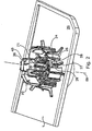
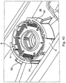
- FIG. 1 shows connection elements 1,2 of a fragmentary, dashed lines schematically illustrated tank 66 and an associated filter cartridge 31.
- a terminal socket 1 is shown, which is fixedly connected to the bottom 29 of the associated tank 66, for example, welded, glued or otherwise secured ,
- the tank connection element 2 of the filter cartridge 31 is inserted.
- the filter-side tank connection element 2 is in Fig. 4 better to see and includes a connection piece 4, which merges into the cartridge housing 36.
- the water passes through lateral slots 6 and then arranged on the cartridge bottom side passage openings 34 into the interior of the cartridge housing 36 and then passes through a filter bed not shown in detail.
- the filter section can be formed in upflow, in downflow or in combination with both flow guides. Through the central outflow pipe 35, the filtered water finally reaches the suction connection 67 water tanks 66 via the tank-side device connection 68.
- the tank-side device connection 68 is shown here for simplification reasons only as an example round-shaped connection piece. However, like the connection socket 1 of the tank-side filter connection, the tank-side device connection 68 can also have coding structures to ensure that only permissible Connection connections can be made. So both with a filter cartridge to be used for the tank and, if desired, with a device suitable for the use of this tank. For the sake of clarity, a graphic illustration of such details for the device connection 68 is omitted and with regard to the embodiments possible for this purpose, reference is made to the embodiments described with regard to the tank-filter connection, which are also valid in their entirety for the tank device connection.
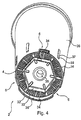
- a first possible embodiment of a tank-side filter cartridge coding is in the Figures 2 and 5 shown as a tank-side filter connection element, the peripheral surface 33 has a polygonal cross-section.
- the polygon is representative of a variety of other possible embodiments as a hexagon.
- a tank-side filter connection element is shown whose peripheral surface represents a polygonal cross-section in the form of a quadrilateral.
- the complementary cartridge connection structure is after insertion of the filter cartridge form-fitting and sealing with its inner circumference 33 on the outer circumference 24, the filter cartridge 31 fixing and sealingly.
- Filter connection socket 23 and the connecting piece 4 of the filter cartridge enclose.
- a perfect, large-area seal between the fresh water side in the interior of the tank 66 and the side of the filter device for device supply via the suction connection 67 located at the connection opening 35 is ensured.
- the tank-side filter connection element 23 may be formed as a complementary structure in the form of a recess with a corresponding inner circumference, on which in turn the sealing surface 33 of the filter cartridge can preferably abut positively and surface sealing, whereby in turn at the same time a sufficient fixation of the filter cartridge 31st is guaranteed at the tank 66.
- the tank-side connection socket 23 (FIG. FIG. 2 ) has a hexagonal outer contour, whose outer peripheral surface forms a sealing surface 24. Outside the base 23, outer shells 25 oriented approximately parallel to a longitudinal axis 69 extending through the connection are arranged in the direction of a filter cartridge 31 to be inserted, which are suitable for at least partially enclosing a filter cartridge housing or its connection region from outside.
- locking elements 26 are attached, which ensure that only a narrow, matching the sealing surface 24 seal can be inserted into the region of the terminal socket 23.
- Bottom ribs 27, 28 prevent sealing against the tank bottom 29, as well as inner ribs 30 prevent sealing by means of an inner radial seal.
- the bottom ribs are preferably arranged radially and / or tangentially with respect to the connecting piece 23 aligned near the bottom.
- the inner ribs 30 project inwardly and / or upwardly beyond an upper edge 71 of the terminal socket 23.
- the inserted filter cartridge 31 is provided with a molded seal 32, which accordingly also has a hexagonal cross-section (see FIG. 3 ).
- the inner surface of the molded seal 32 forms the sealing surface 33.
- the illustrated embodiment comprises further coding structures.
- snap elements 37 are formed on the outside of the filter cartridge housing 36 .
- the snap elements 37 can be inserted into corresponding receptacles 38 of the outer shells 25.
- the filter cartridge 31 can easily sit in the correct angular position without resistance.
- the molded seal 32 aligned with respect to the sealing surface 24 of the connection socket 23 so that it can be inserted further in the axial direction.
- the snap element 37 snaps over the.
- Fig. 5 shows a schematically illustrated embodiment with angle-dependent adjustable amount of waste.
- the tank bottom 52 is only partially shown in the connection area of the filter cartridge 53.
- the tank bottom 52 comprises a hexagonal connection base 54, which slightly converges towards the top in order to improve the sealing effect in relation to a purely vertical alignment of the base walls and / or as a further coding structure in the manner of a truncated pyramid. This cross-sectional taper is barely visible in the perspective view.
- the outer surfaces 55 of the terminal socket also serve as a sealing surface to seal the drain line 56 with the filter cartridge 53 mounted completely or partially with respect to the interior of the tank.
- the filter cartridge 53 has a socket-shaped seal 57 corresponding to the connection socket 54.
- the individual walls 58 are the same length except for a wall 59 in the axial direction A.
- the wall 59 is provided with a lower-side recess 60, whose function will be explained in more detail below.
- the outlet 61 can be seen from the filter cartridge 53 through which the filtered water enters the drainage line 56.
- bypass openings 65 are arranged to be be tightly closed by the longer-trained Dichturgs109n 58 when attaching the filter cartridge 53. Only where the wall 59 with recess 60 is used can the bypass openings 65 remain open, so that water filtered via the recess 60 directly from the tank to the region of the discharge line 56.
- the angular arrangement of the filter cartridge i. with the selection of the scoop wall 62, 63, 64, to which the recess 60 is attached, the size of the free cross section of the bypass openings 65 set.
- the cross-sectional openings of the multipassed bypass ports 65 add up.
- differently sized bypass ports 65 may also be provided. Due to the different cross sections of individual bypass openings 65 or in the sum of several bypass openings 65 on a base wall, for example, the base wall 64, different proportions of unfiltered water, the filtered water are added. This results in a blend setting, which is dependent on the angular position of the filter cartridge 53.
- a blend setting can, for example, by the formation of an actuatable by the filter cartridge driver element in the form of a rotatably adjustable in its position terminal socket 54.1 as shown in the FIG. 5a will be realized.
- the bottom 54.2 of the rotatable connection socket 54.1 here has, for example, three bypass openings 65.1 and, depending on the rotational position relative to the tank bottom 52, can be arranged such that complementary bypass openings 65.2 arranged in the tank bottom 52 are released or closed in a fluid-conducting manner.
- FIG. 6 In this illustration, purely by way of example four different settings are shown, the shown Rotary position with closed bypass and three other positioning options, with the release of one, two or all three by-pass holes 65.1 by matching their position with the corresponding bypass holes 65.2.
- a possible separation variant between the bypass holes 65.1 connected to the tank-side fresh water connection and the exemplary centrally arranged drainage line 56 would be the arrangement of an intermediate seal, in particular and preferably an axial seal, which sealingly extends between the end face of the filter-like tank connection element and the bottom 54.2 of the connection base 54.1 , Conceivable, however, are also quite possibly other additional separating and / or sealing elements between the fresh water side and the side of the filtered water.
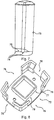
- connection socket 72 which has a quadrangular contour in plan view and in which a correspondingly shaped cartridge 73 with a complementary, also in cross-section square connector is plugged in.
- connection socket 72 which has a quadrangular contour in plan view and in which a correspondingly shaped cartridge 73 with a complementary, also in cross-section square connector is plugged in.
- FIGS. 7 and 8 show the cartridge 73 and the connecting element 72 each in a sole representation.
- three of four provided feet 74 can be seen, between each of which a sufficiently large inlet opening 75 for the entry of fresh water is formed with the cartridge 73 inserted in the connecting element 72.
- the connecting element 72 has correspondingly complementary inlet openings for the passage of the fresh water from the tank to the filter cartridge 73.
- An example of the terminal socket 23 corresponding terminal base 77 is formed centrally on a bottom plate 78 of the connecting element 72, again in the form of a projection.
- This connecting base 77 designed as a projection has on its outer peripheral surface a sealing surface 79, which sealingly separates the fresh water region from the region of the water filtered through the filter in relation to a complementary receiving structure arranged on the filter cartridge.
- the connection socket 77 can be impressed with an at least slightly conical shape, so that the cartridge to be mounted with its connection piece is easier to set up on the one hand and a larger surface for the sealing between the two elements for mutual covering on the other hand can.
- FIGS. 9 and 10 each show a cartridge 73 in a bottom view, in which a complementary to the terminal socket 77 molded seal 81 is shown with a sealing surface 80 formed therein. Centrally located in the middle of the outlet 82 can be seen for the filtered water, which can flow through the inlet slots 34 in the filter.
- FIGS. 11 and 12 each show a longitudinal section through the connecting element 72 and a cartridge inserted therein 73, once along the broad side ( FIG. 11 ) and once along the long side ( FIG. 12 ), which in plan view rectangular connection structure.
- FIGS. 13 and 14 show two sections in the connecting region between the connection base 77 and cartridge 73 with a molded seal 81 arranged therein, in each case in a different depth lying cutting plane. Especially in the FIG. 14 It can be clearly seen that in addition to the positive connection between the molded seal 50 and the connection base 77, a fixing effect between the extended outer wall 83, the filter cartridge 73 and the elements of the outer shell 84 is given, preferably also in a positive manner.
- FIGS. 15 and 16 show two more sectional views according to the FIGS. 13 and 14 , but again in different deep cutting planes.
- FIG. 17 finally shows a further, fragmentary representation on an even larger scale.
- FIG. 18 in addition to one in comparison to the embodiments in FIGS. 1 to 4 described socket filter connection in the form of a projection 23 on the tank-side filter connection element 23 has a complementary shape as formed in the tank bottom 29 recess 23 in which mutatis mutandis all coding possibilities described in the first embodiment can also be realized here, either the same and / or complementary or in combined embodiments.
- the second essential feature shows the FIG. 18 the possibility of using adapters 85, 86.
- the adapter 85 is shown purely by way of example for connecting a filter cartridge 73 also shown as an example to a tank-side filter port 1, wherein the embodiment of the filter port 1, in particular its base 23, as already explained above, both protruding base as well as recessed groove can be realized.
- the illustrated embodiments show the most diverse coding structures that are to be provided according to the invention. In any case, it is ensured that only suitably adapted filter cartridges with key function fit into the corresponding tank-side filter connections.
- FIG. 19 Two further embodiments of coding of the connection between the tank and the filter are based on the Figures 19 and not shown and described according to the invention.
- the housing of the filter cartridge 53 itself has a polygonal outer contour in the form of a hexagon, which according to the invention can not be inserted into a complementary tank-side polygonal coding and / or fixing structure 23.
- the solid lines show the filter cartridge 53 in a view obliquely from below with a basically flat bottom in the middle of the filter outlet 35 for the filtered water is exemplified as a cylindrical protruding tube with two end-side axially projecting lugs 35.1 and 35.2.
- This cylindrically projecting outlet member 35 is coded by the two axially projecting wings and forms with its end face opposite the end face of a complementary formed in the tank-side filter port outlet and receiving element 68 with its in the Kodiernuten 68.1 and 68.2 an axial coding and / or sealing structure or -contour.
- the filter cartridge 53 can only be functional, not according to the invention, inserted into the tank-side filter connection element 1 when the end face of the filter outlet 35 sealingly mates with the end face of the tank-side device outlet 68.
- the housing 36 of the filter cartridge 53 is shown extended by the dashed lines as compared to the previously described filter bottom.
- FIG. 20 shows in contrast, not according to the invention, a modified embodiment in such a way that the housing 36 of the filter cartridge is shown as an example round and the filter outlet 35 as a polygonal structure, here again by way of example as a hexagon, which in addition again a frontal coding in the form of two axially projecting, coding, triangular tips or wings.
- the filter cartridge can only be functional with the tank side
- Filter connection element 1 are connected when the two outlet structures 35 and 68 can be added to the front side axially sealingly to each other.
- the presentation of further coding and / or fixing structures has been omitted for reasons of clarity. However, all the structures already described above can also be provided accordingly here. Also for the two embodiments according to the Figures 19 and 20 applies that these coding structures, not according to the invention, between the filter side and tank side can be reversed and / or modified and / or supplemented by other contours and / or structures.
- FIGS. 21 to 32 show further possible, not according to the invention.
- Embodiments of Encryption and / or Fixation Structures for Tank Filter Connection Elements This show the FIGS. 21 to 24 a first, the FIGS. 25 to 28 a second and the FIGS. 29 to 32 a third possible embodiment of bayonet connections, in particular double or multiple bayonet connections.
- FIGS. 21 to 32 show the filter-side tank connection coding or fixing structure with in plan view corresponding FIG. 22 eight projections 21.1 and 21.2, according to the FIG. 21 along the longitudinal extension of the filter-side tank connection element both axially and in a radial angular position offset from each other as two pairs of four are formed.
- the complementary connection or coding structures 20 are in the tank-side filter connection element 19 in the FIGS. 23 and 24 shown. In this embodiment is according to the FIG.
- FIGS. 25 to 32 represent similar, not according to the invention embodiments, but with respect to the embodiments 21 to 24 modified contours of the openings 20 and the coding projections 21 complementary thereto as well as with respect to axially and viewed in plan angularly changed orientations.
- Embodiments 21 to 24 there are eight in total on two levels and in Embodiments 25 to 32 respectively, only six as two triple-coded protrusion levels.
- these coding structures described herein may readily be combined with other e.g. axially aligned coding structures are combined to allow even further differentiation possibilities for individual tank-filter connection connections.
- FIGS. 33 to 40 show a further embodiment of a tank-filter connection connection in different views and representations such as oblique plan views, sectional views, front view and bottom view of the filter cartridge 29 and a plan view of the tank side Filter connection element with and without inserted filter-side tank connection element ( Fig. 39 and 40 ).
- the essential features of the embodiment of a tank filter connection connection are the frontally projecting from the filter cartridge 31, such as wedge-shaped tips S and arranged between them grooves N.
- the tips can also be used for positioning when inserting the filter cartridge in the tank connection piece, in particular in optically non-visible terminals, e.g. to prevent damage to the sealing and / or other structures.
- the slot spacings and / or the slot widths and / or the widths of the tips or projecting wings as well as their lengths and / or distances, which must correspond to corresponding structures on the tank-side filter connection element, are particularly suitable for coding Filter cartridge to allow.
- ribs R formed on the tank-side filter connection element.
- FIG. 39 whose interaction with the coding and / or fixing structures N and S formed on the filter-side tank connection element are best described in US Pat FIG. 40 are recognizable.
- the ribs R are in this case formed on a filter-side tank connection element partially enclosing, wall-shaped base SO.
- the coding and / or fixing structure described above may also be complementary in a modified embodiment, ie grooves instead of ribs and ribs instead of grooves.
- a mixed or combined coding and / or fixing structure by forming grooves and ribs on the one and / or other tank or filter-side connection element is quite possible.
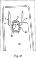
- FIGS. 41 to 43 represent a further embodiment in which the filter 31 arranged along a tank wall, two angularly shaped ribs R having and engaging in two complementary slots S guide is inserted into the interior of the tank.
- the tank has in its bottom 29 a polygonal, here hexagonal, filter connection element 23 and from within this connection element through the tank wall leading to the outside tank drain opening 35.
- the polygonal connecting element 23 is formed as at the bottom of the tank with bevelled at its top polygon.
- the filter-side tank connection element 32 in the form of a conically shaped, likewise polygonal shaped seal 32 has a correspondingly complementary inclined connection surface.
- a bypass structure may be formed to allow a blending of the filtered water.
- a complementary rib-shaped structure R and a complementary, slot-shaped coding structure S is here by the front-side recess S in the filter wall and the complementary shape R of the outlet opening 35 formed in the bottom region of the tank wall.
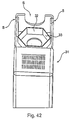
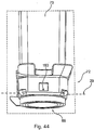
- FIGS. 44 to 47 Another embodiment of a square coding for a tank-filter connection are through the FIGS. 44 to 47 shown.
- This embodiment has, in addition to those in the FIGS. 6 to 17 illustrated embodiments on a bypass structure.
- This bypass structure has in the end-face housing extension of the filter cartridge 73 an opening in the form of a bore 129 which, in overlap with an opening formed in a tank-side filter base connection member 165 opening 165 the flow of raw water in the tank to the tank-side device connection in the discharge area of the tank for admixing with the filtered through the filter cartridge water allows.
- the filter port on the bypass opening 129 is formed in the frontal extension of the filter and realizes a waste device in combination with the tank-side filter connection element 77th
- a further waste structure can be realized by the formation of a bypass opening 129.1 in the polygonal, filter-side tank connection element 32, here in the form of a four-edged molded seal 32, which in turn is connected to the in the tank-side filter port 77 formed opening 165 corresponds.
- the size of the opening 161.1 in turn determines the amount of waste.
- the waste device is realized directly in the sealing region of the polygonal-shaped tank filter connection.
- FIGS. 48 and 49 show an embodiment of a tank-filter connection, in which a through the filter-side tank connection element 4 extending longitudinal axis II is obliquely aligned with respect to a running through the housing of the filter cartridge 31 longitudinal axis I, here preferably at an acute angle ⁇ .
- This oblique or even cranked or also beveled orientation of the filter-side tank connection element 4 relative to the rest of the filter housing forms a further form of mechanical coding, which can be combined with other, already described above, coding forms, in particular with a polygonal connecting element shown here in the form of a octagon.
- This octagon is also formed as a molded seal and, as shown here, a bypass or Verites in the form of an opening 129 which allows in the presence of a complementary element in the tank-side filter connection element a corresponding waste of the water to be filtered.
- FIG. 48 shows the filter cartridge 31 in an oblique view from below, in which the filter-side connection element 4 and its essential features can be seen.
- FIG. 49 a side view in which the bend between the cartridge housing 31 and the filter-side tank port 4 is shown for an exemplary angle shown.
- FIG. 50 shows a further embodiment in which the tank 66 is again designed as a Einschubtank in which a cartridge 31 is connected to filter the water contained therein to a tank workedem filter connection element 2.
- This tank-side connection element 2 is connected via a line, here preferably in the form of a stable tube, to the tank-side device connection 68.
- This tank-side device port 68 is guided by the operational bottom side region of the tank 66 spaced from the tank interior to the outside.
- the device connection 68 is fixed by way of example in a recess embedded in the upper edge of a tank wall, which can be advantageously designed as a releasable connection, so that an easy removal and cleaning is made possible.
- the operation of the tank is possible by simply inserting into a suitably trained recording a device, or its filling with fresh, then filtered through the filter 31 by pulling out water.
- the tank-side filter connection element 2 may in this case all coding and / or fixing and / or sealing features described above, so that reliably in this second drawer embodiment, the use of a non-operationally provided filter cartridge can be excluded, which incidentally also for the execution after the FIGS. 41 to 43 applies.
- FIGS. 51 to 54 Two further embodiments with respect to a bypass configuration between a tank-side filter connection element 1 and a filter-side tank connection element 2 are in the FIGS. 51 to 54 shown.
- the FIGS. 51 and 52 show here, not according to the invention, by way of example and schematically a bypass arrangement BY, which allows a blend between filtered through the filter cartridge 53 water and a not or otherwise filtered or treated water.
- the bypass or blending line BY is in this embodiment combined with a bayonet catch BJ in such a way that an opening BY is provided in a bayonet wing BJ which corresponds to a further bypass opening BY arranged on a bayonet slot BJ which is complementary to the bayonet wing Inserted filter cartridge a corresponding bypass guide is realized.
- the bypass opening BY shown in the tank-side filter connection element 1 is guided from the front-side connection region of the tank-side connection socket to below the point in which the filter-side tank connection piece 4 ends in operationally inserted position, so that the bypass water passing by the filter bed of the filter cartridge 53 with the through the filter bed the filter cartridge 53 filtered water mixed and the tank-side device port 68 is supplied.
- FIGS. 53 and 54 show a contrast modified embodiment, that the bypass line BY is guided over a separate from a main filter bed HF of the filter cartridge 53 processing and / or filter section, which is exemplified here and symbolically as Maufilterumble NF.
- This second treatment and / or filter section NF may contain, for example, an activated carbon filter section and / or other treatment mechanisms and / or media.
- the water guided over this bypass section BY is mixed with the water filtered through the filter section EF of the filter cartridge 53, so that it can likewise be removed through the tank-side device connection 68.
- the merging of the two water passages guided or prepared separately via the main filter HF and via the sub-filter NF inside the filter cartridge 53 is exemplarily and schematically represented by an opening into the inner downpipe of the filter cartridge 53.
- a separate outlet opening out of the filter cartridge may well be provided in the direction of the tank-side appliance connection 68, where applicable for all three embodiments, that they all open inside the tank-side filter connection nozzle 32, so that in turn For example, a seal by a positive connection of Both polygonal connection elements of the tank and the filter are possible.
- the introduction of the bypass flow in the secondary filter section is only possible if the opening also acting as coding opening BY is plugged into the axially from the tank bottom 29 high encryption element 25 with the corresponding filter-side bypass opening BY in the operationally provided state. If no overlap of these two openings is given, then no corresponding waste can be realized.
- the tank-side filter port 1 according to the FIG. 53 is likewise shown only schematically and by way of example and can be provided with a wide variety of variants of the coding and connection structure already described above, so that optionally only a single one of all six possible angular orientations for an allowable filter termination is enabled. From the representation of such coding structures was omitted at this point for reasons of clarity.
- FIGS. 51 to 54 Basically, also applies to these embodiments in the FIGS. 51 to 54 in that they too can be combined with all the coding and / or fixing and / or sealing structures described above and / or.
- FIGS. 55 to 57 show two further embodiments of a tank in which the filter cartridge outside the main vessel of the tank 66 but further, as described so far, between the tank-side filter connection element 1 and a tank workedem device port 68 is arranged to store in the tank raw water before being supplied to a sampling point or to filter a correspondingly connected device with or without waste.
- FIG. 55 shows a plan view of a tank 66, the tank wall 66.1 together with another tank wall 66.2 a housing 66.5 for receiving a correspondingly shaped Filter cartridge 31 is formed and liquid-conducting connected to the interior of the tank.
- a tank-side filter connection element 1 is shown, here by way of example as a coded connection structure in the form of a polygon contour.
- a drain opening 68.1 is provided for connection to the tank-side device connection element 68.
- FIG. 56 shows this tank 66 in a sectional view across the filter cartridge receiving housing 66.5 and the adjacent elements of the tank and the underlying connection structure for the tank-side device connection element 68.
- the tank could be installed, for example, as a plug-in tank in a suitably designed devices.
- the supply of the water filled in the interior of the tank 66 to the filter cartridge 31 takes place through an opening 66.4 in the tank wall 66.2, which may be formed, for example, in the form of a tank wall 66.1 which does not extend completely to the tank bottom 29.
- the raw water to be filtered thus stands in the interior of the filter housing 66.5 formed by the two tank walls 66.1 and 66.2 the same height as in the interior of the water tank 66.
- the Figure 57 shows an embodiment in which the liquid-conducting connection between the tank-side filter connection element 1 and the filter side Tank connection element 2, not according to the invention, completely outside the tank 66.
- the tank bottom 29 is further developed by way of example at a location opposite a tank wall 66.1 outwardly and formed into a closed liquid line 66.3, through which the water located in the interior of the tank 66 to the tank-side filter connection element 1 formed outside of the tank 66 in this example flows.
- the filter cartridge 31 is connected with its filter-side tank connection element 2. It is also true for this embodiment that all features already described above with respect to a coding and / or sealing and / or fixing and / or adapter structure can be provided in any embodiment variant or have validity.
Landscapes
- Engineering & Computer Science (AREA)
- Chemical & Material Sciences (AREA)
- Food Science & Technology (AREA)
- Life Sciences & Earth Sciences (AREA)
- Hydrology & Water Resources (AREA)
- Environmental & Geological Engineering (AREA)
- Water Supply & Treatment (AREA)
- Organic Chemistry (AREA)
- Chemical Kinetics & Catalysis (AREA)
- Water Treatment By Sorption (AREA)
- Separation Using Semi-Permeable Membranes (AREA)
- Apparatus For Making Beverages (AREA)
- Details Of Rigid Or Semi-Rigid Containers (AREA)
- Devices For Dispensing Beverages (AREA)
- Loading And Unloading Of Fuel Tanks Or Ships (AREA)
- Beverage Vending Machines With Cups, And Gas Or Electricity Vending Machines (AREA)
- Filtration Of Liquid (AREA)
Applications Claiming Priority (2)
| Application Number | Priority Date | Filing Date | Title |
|---|---|---|---|
| DE102006037636 | 2006-08-10 | ||
| EP07818019.7A EP2049218B1 (de) | 2006-08-10 | 2007-08-10 | Tank |
Related Parent Applications (3)
| Application Number | Title | Priority Date | Filing Date |
|---|---|---|---|
| EP07818019.7A Division EP2049218B1 (de) | 2006-08-10 | 2007-08-10 | Tank |
| EP07818019.7A Division-Into EP2049218B1 (de) | 2006-08-10 | 2007-08-10 | Tank |
| EP07818019.7 Division | 2007-08-10 |
Publications (3)
| Publication Number | Publication Date |
|---|---|
| EP2433906A2 EP2433906A2 (de) | 2012-03-28 |
| EP2433906A3 EP2433906A3 (de) | 2013-10-30 |
| EP2433906B1 true EP2433906B1 (de) | 2016-06-15 |
Family
ID=38896127
Family Applications (6)
| Application Number | Title | Priority Date | Filing Date |
|---|---|---|---|
| EP11008696.4A Active EP2433906B1 (de) | 2006-08-10 | 2007-08-10 | Wasserfilterpatrone |
| EP07818017.1A Active EP2063972B1 (de) | 2006-08-10 | 2007-08-10 | Tank |
| EP07818018.9A Active EP2049221B1 (de) | 2006-08-10 | 2007-08-10 | Tank |
| EP07818019.7A Active EP2049218B1 (de) | 2006-08-10 | 2007-08-10 | Tank |
| EP07818020A Withdrawn EP2049219A2 (de) | 2006-08-10 | 2007-08-10 | Tank |
| EP07818021.3A Revoked EP2049220B1 (de) | 2006-08-10 | 2007-08-10 | Tank |
Family Applications After (5)
| Application Number | Title | Priority Date | Filing Date |
|---|---|---|---|
| EP07818017.1A Active EP2063972B1 (de) | 2006-08-10 | 2007-08-10 | Tank |
| EP07818018.9A Active EP2049221B1 (de) | 2006-08-10 | 2007-08-10 | Tank |
| EP07818019.7A Active EP2049218B1 (de) | 2006-08-10 | 2007-08-10 | Tank |
| EP07818020A Withdrawn EP2049219A2 (de) | 2006-08-10 | 2007-08-10 | Tank |
| EP07818021.3A Revoked EP2049220B1 (de) | 2006-08-10 | 2007-08-10 | Tank |
Country Status (10)
| Country | Link |
|---|---|
| US (4) | US8202418B2 (zh) |
| EP (6) | EP2433906B1 (zh) |
| JP (3) | JP5244796B2 (zh) |
| KR (3) | KR101660043B1 (zh) |
| CN (4) | CN102794043B (zh) |
| DE (6) | DE102007038018A1 (zh) |
| ES (2) | ES2589125T3 (zh) |
| PL (3) | PL2433906T3 (zh) |
| RU (3) | RU2009108270A (zh) |
| WO (5) | WO2008017508A2 (zh) |
Cited By (4)
| Publication number | Priority date | Publication date | Assignee | Title |
|---|---|---|---|---|
| DE102021122619A1 (de) | 2020-09-03 | 2022-03-03 | Kurt Wallerstorfer | Filterpatrone |
| DE102021122574A1 (de) | 2020-09-03 | 2022-03-03 | Kurt Wallerstorfer | Wassertank mit Filterpatrone |
| DE102021122626A1 (de) | 2020-09-03 | 2022-03-03 | Kurt Wallerstorfer | Wassertank mit Filterpatrone |
| DE102022106568A1 (de) | 2021-03-22 | 2022-09-22 | Kurt Wallerstorfer | Wassertank mit Filterpatrone |
Families Citing this family (64)
| Publication number | Priority date | Publication date | Assignee | Title |
|---|---|---|---|---|
| MXPA05003719A (es) | 2003-10-07 | 2005-06-17 | Conteyor Multibag Systems Nv | Armazon plegable. |
| US8292984B2 (en) | 2007-07-20 | 2012-10-23 | Donaldson Company, Inc. | Air cleaner arrangments with end support for cartridge; components; and, methods |
| DE102008010914A1 (de) * | 2008-02-25 | 2009-08-27 | Braun Gmbh | Getränkemaschine mit einem Wassertank und einer Wasserfilterkartusche |
| EP2095749A1 (en) * | 2008-02-28 | 2009-09-02 | Nestec S.A. | Beverage machine with a water tank |
| DE102008029533A1 (de) * | 2008-06-21 | 2009-12-24 | Krones Ag | Vorrichtung zum Handhaben, insbesondere Filtrieren von Flüssigkeiten |
| DE102009025437A1 (de) | 2008-06-27 | 2009-12-31 | Aquis Wasser-Luft-Systeme Gmbh, Lindau, Zweigniederlassung Rebstein | Wassertank und damit verbindbares, separat ausgebildetes Filterpatronen-Anschlusselement |
| DE102008002727B4 (de) * | 2008-06-27 | 2020-12-17 | Brita Gmbh | Vorrichtung zur Behandlung von Wasser, insbesondere Filtervorrichtung, und Kartusche |
| PT2168469E (pt) * | 2008-09-25 | 2013-08-22 | Nestec Sa | Cartucho de filtro para uma máquina de bebidas e máquina de bebidas com um cartucho de filtro |
| US9480940B2 (en) | 2009-03-31 | 2016-11-01 | Donaldson Company, Inc. | Liquid filter assemblies; features; components; and, methods |
| US8783471B2 (en) | 2009-04-20 | 2014-07-22 | Parker Hannifin Manufacturing Netherlands (Filtration) B.V. | Filter assembly, a filter element, and a method for replacing a filter element |
| EP2272801A3 (de) * | 2009-06-25 | 2012-06-06 | Aquis Wasser-Luft-Systeme GmbH Lindau, Zweigniederlassung Rebstein | Wasserfilter mit Härtereduzierer und Resthärtestabilisator |
| WO2011067171A1 (en) * | 2009-12-01 | 2011-06-09 | Nestec S.A. | Flowmeter assembly for a beverage machine |
| EP2533649B1 (en) * | 2010-02-11 | 2019-03-13 | Brinee Home Solution Ltd. | Food products serving and preserving device |
| DE102010011290A1 (de) * | 2010-03-13 | 2011-09-15 | Mahle International Gmbh | Filtereinrichtung |
| JP5860878B2 (ja) * | 2010-08-06 | 2016-02-16 | ベコー テヒノロギース ゲーエムベーハー | カートリッジ式油分離器 |
| WO2012020360A1 (en) * | 2010-08-13 | 2012-02-16 | Koninklijke Philips Electronics N.V. | A water container and a machine for making beverages comprising said container |
| CN102462381A (zh) * | 2010-11-16 | 2012-05-23 | 绳帆 | 袋装水取水装置 |
| GB2485553B (en) * | 2010-11-17 | 2014-01-22 | Richards Morphy N I Ltd | Electric iron with nozzle for water mist |
| US8858795B2 (en) * | 2011-03-22 | 2014-10-14 | Jeffrey G McLane | Filter apparatus |
| DE102011101292B4 (de) * | 2011-05-10 | 2013-11-28 | Fette Compacting Gmbh | Codierelement für die Bestückung mindestens eines Kurventrägers eines Rotors einer Rundläuferpresse und Verfahren zum Bestücken eines Kurventrägers eines Rotors einer Rundläuferpresse sowie Steuerkurvenanordnung und Rotor für eine Rundläuferpresse |
| DE102011105555A1 (de) * | 2011-06-25 | 2012-12-27 | Hydac Filtertechnik Gmbh | Filtervorrichtung |
| US10556220B2 (en) | 2012-06-29 | 2020-02-11 | 3M Innovative Properties Company | Media cartridge with adjustable bypass |
| EP2705784B2 (de) * | 2012-09-06 | 2018-11-28 | Miele & Cie. KG | Getränkebereiter |
| US9327216B2 (en) | 2012-11-12 | 2016-05-03 | Whirlpool Corporation | Customizable multi-stage water treatment system |
| US9314716B2 (en) * | 2012-11-12 | 2016-04-19 | Whirlpool Corporation | Customizable multi-stage water treatment assembly |
| US9067161B2 (en) | 2012-11-29 | 2015-06-30 | Donaldson Company, Inc. | Filter cartridges; features and methods of assembly; air cleaner assemblies; and, filter cartridge combinations |
| ITPD20130051A1 (it) * | 2013-03-01 | 2014-09-02 | Laica Spa | Filtro e serbatoio per macchina per la preparazione di bevande calde |
| ITMI20130660A1 (it) * | 2013-04-22 | 2014-10-23 | Emanuela Paci | Stazione di stoccaggio, prelievo e ricircolo di una sostanza fluida |
| CA2912723C (en) * | 2013-05-23 | 2017-02-07 | 2266170 Ontario Inc. | Capsule housing |
| DE102014002505A1 (de) | 2013-07-05 | 2015-01-08 | Aqua Select Gmbh | Anordnung zum Reinigen von Wasser |
| US10178921B1 (en) | 2013-08-06 | 2019-01-15 | Brita Lp | Mechanisms and systems for filter seating |
| ITPD20130326A1 (it) * | 2013-11-28 | 2015-05-29 | Laica Spa | Cartuccia filtrante per macchina per la preparazione di bevande |
| GB2515847B (en) * | 2013-12-04 | 2015-05-27 | Design Reality Ltd | Respirators |
| CN106660834B (zh) * | 2014-08-15 | 2021-08-06 | 阿尔弗雷德·卡赫欧洲两合公司 | 用于蒸汽设备的水处理罐筒和蒸汽设备 |
| DE102015011801A1 (de) | 2014-09-22 | 2016-03-24 | Mann + Hummel Gmbh | Filter mit widerhakenförmiger Bajonettaufnahme und Filterelement |
| DE102015209986A1 (de) * | 2015-05-29 | 2016-12-01 | BSH Hausgeräte GmbH | Getränkeautomat |
| DE102015007692A1 (de) * | 2015-06-09 | 2016-12-15 | Rt-Filtertechnik Gmbh | Filterelement |
| TWI702931B (zh) * | 2015-09-02 | 2020-09-01 | 德商碧然德有限公司 | 用於形成液體處理設備的頭部部分、組裝其之部件與方法和液體處理設備 |
| RU2615329C1 (ru) * | 2015-12-09 | 2017-04-04 | Публичное акционерное общество "Транснефть" (ПАО "Транснефть") | Способ маркировки трубных изделий, трубное изделие с маркировкой и система идентификации трубных изделий |
| ITUB20156834A1 (it) * | 2015-12-10 | 2017-06-10 | Fernando Tateo | Sistema a garanzia igienica per erogazione da tanica di liquidi destinati a distributori automatici di bevande istantanee |
| BR122020018481B1 (pt) | 2015-12-18 | 2022-07-26 | Donaldson Company, Inc | Cartuchos de filtro e montagens de purificador de ar |
| US20170265674A1 (en) * | 2016-03-16 | 2017-09-21 | Hongjiang Liu | Cup with filtering system |
| US10709283B2 (en) * | 2016-10-31 | 2020-07-14 | Blue Bottle Coffee, Inc. | Flow-optimized pour over coffee brewing system |
| EP4039353A1 (en) | 2016-11-04 | 2022-08-10 | Donaldson Company, Inc. | Filter elements, air cleaner assemblies, and methods of use and assembly |
| CN208582332U (zh) * | 2017-01-26 | 2019-03-08 | 深圳洛克时代科技有限公司 | 智能清洁设备用水箱及智能清洁设备 |
| EP3401000A1 (en) | 2017-05-09 | 2018-11-14 | Donaldson Company, Inc. | Adapter and air filter cartridge being adapted for use with such an adapter |
| EP3717102A1 (en) | 2017-11-27 | 2020-10-07 | Donaldson Company, Inc. | Air cleaner assemblies and methods of use |
| US11872506B2 (en) * | 2018-07-07 | 2024-01-16 | Paragon Water Systems, Inc. | Water filter cartridge having an air vent |
| DE102018009203B4 (de) | 2018-11-23 | 2022-10-20 | Christoph Götz | Filterpatrone und Filtervorrichtung |
| WO2021013349A1 (de) | 2019-07-24 | 2021-01-28 | Alfred Kärcher SE & Co. KG | WASSERBEHANDLUNGSKARTUSCHE FÜR EIN HEIßFLUIDREINIGUNGSGERÄT, HEIßFLUIDREINIGUNGSGERÄT UND VERFAHREN ZUR BEHANDLUNG VON WASSER |
| WO2021094014A1 (en) * | 2019-11-15 | 2021-05-20 | Brita Gmbh | Filtration system with a filter cartridge and a seat element for the filter cartridge |
| JP7468198B2 (ja) | 2020-07-01 | 2024-04-16 | 東レ株式会社 | コーヒーメーカー用浄水カートリッジ、およびそれを装着したコーヒーメーカー |
| CN214017136U (zh) * | 2020-07-13 | 2021-08-24 | 天津市远大工贸有限公司 | 一种咖啡机及其咖啡机滤芯 |
| DE202021003989U1 (de) * | 2020-09-03 | 2022-03-31 | Kurt Wallerstorfer | Filter mit Zentrierung |
| DE102020129760A1 (de) | 2020-11-11 | 2022-05-12 | Miele & Cie. Kg | Getränkebereiter mit Wasseraufbereitungselement |
| DE102020130525A1 (de) | 2020-11-19 | 2022-05-19 | Miele & Cie. Kg | Getränkeautomat und Verfahren zur Ansteuerung eines Ventils eines Bypasses eines Wasserfilters in einem derartigen Getränkeautomaten |
| DE102020130961A1 (de) | 2020-11-24 | 2022-05-25 | Miele & Cie. Kg | Getränkebereiter mit Aufnahmevorrichtung für ein Filterelement |
| WO2022229927A1 (en) | 2021-04-30 | 2022-11-03 | Whirlpool Corporation | Filter assembly |
| CN113371662B (zh) * | 2021-05-21 | 2022-11-11 | 鹿啄泉矿泉水有限公司 | 空气零接触上水器及保鲜取液系统 |
| DE102021115661A1 (de) | 2021-06-17 | 2022-12-22 | Miele & Cie. Kg | Getränkeautomat |
| DE102021117623A1 (de) | 2021-07-08 | 2023-01-12 | Miele & Cie. Kg | Wassertank, Filtereinheit, Wassertanksystem und Getränkezubereitungsgerät |
| DE102021122326A1 (de) | 2021-08-30 | 2023-03-02 | Miele & Cie. Kg | Getränkeautomat und Verfahren zur Herstellung eines Aufgussgetränkes mit einem als Tee- oder Kaffeeautomaten ausgeführten Getränkeautomaten |
| BE1030170B1 (de) | 2022-01-10 | 2023-08-10 | Miele & Cie | Filtereinheit, Wasserführender Automat mit einer derartigen Filtereinheit, Verfahren zur Erkennung des Gebrauchszustandes einer Filtereinheit und Verfahren zur Bestimmung der Lebensdauer einer Filtereinheit |
| TWI805280B (zh) * | 2022-03-17 | 2023-06-11 | 台灣櫻花股份有限公司 | 淨水用的濾心組 |
Citations (5)
| Publication number | Priority date | Publication date | Assignee | Title |
|---|---|---|---|---|
| DE19717054C2 (de) | 1997-04-23 | 1999-07-29 | Aweco Kunststofftech Geraete | Wasserbehälter mit Filterpatrone |
| DE29921168U1 (de) | 1999-12-02 | 2001-04-05 | Hengst Walter Gmbh & Co Kg | Flüssigkeitsfilter mit demontierbarem, zentralen Bauteil, mit zusätzlichem Haltebauteil |
| US6458269B1 (en) | 2000-04-20 | 2002-10-01 | Cuno Incorporated | Keyed filter assembly |
| DE102004049877A1 (de) | 2004-10-13 | 2006-04-27 | Brita Gmbh | Filterkartusche und Sitzelement für eine Filterkartusche |
| EP1867606A1 (de) | 2006-06-14 | 2007-12-19 | Elfo AG | Wasserfilterkartusche für einen Wassertank |
Family Cites Families (53)
| Publication number | Priority date | Publication date | Assignee | Title |
|---|---|---|---|---|
| CH432395A (de) | 1965-12-03 | 1967-03-15 | Sanzenbacher Wilhelm | Gerät zur Aufbereitung von Trinkwasser |
| US3206033A (en) * | 1962-03-22 | 1965-09-14 | Met Pro Inc | Liquid dispenser for the purification and filtration of water |
| DE3014493A1 (de) | 1980-04-16 | 1981-10-22 | Emide-Metallindustrie Gebr. Streicher, 7209 Denkingen | Haushaltsgeraet mit heisswasserbereiter |
| JPS6115002U (ja) * | 1984-07-04 | 1986-01-28 | 三菱レイヨン株式会社 | 中空糸瀘過モジユ−ル |
| DE3810441C2 (de) * | 1988-03-26 | 1994-09-08 | Brita Wasserfilter | Wasserreinigungsvorrichtung mit einem Einlauftrichter |
| JPH037989U (zh) * | 1989-06-13 | 1991-01-25 | ||
| US5342518A (en) * | 1990-02-14 | 1994-08-30 | Iraco Filtration Systems, Inc. | Filtration system and mount for beverage dispensers and automatic beverage brewing machines |
| US5035797A (en) | 1990-02-14 | 1991-07-30 | Stanadyne Automotive Corp. | Key system for filter assembly |
| JPH04904U (zh) * | 1990-04-17 | 1992-01-07 | ||
| GB9101772D0 (en) * | 1991-01-28 | 1991-03-13 | Philips Electronic Associated | A water cleaning device |
| JPH0526833A (ja) * | 1991-07-22 | 1993-02-02 | Matsushita Electric Ind Co Ltd | オゾンセンサ |
| US5186829A (en) * | 1991-08-16 | 1993-02-16 | Stanadyne Automotive Corp. | Fuel filter key system |
| JPH0526833U (ja) * | 1991-09-20 | 1993-04-06 | 株式会社フタバ化学 | 液体容器 |
| FR2708452B1 (fr) | 1993-07-29 | 1997-09-05 | Moulinex Sa | Machine à infusion comportant un dispositif de purification d'eau. |
| JPH08140856A (ja) * | 1994-11-25 | 1996-06-04 | Japan Organo Co Ltd | 飲料サーバー |
| US5702602A (en) * | 1995-12-20 | 1997-12-30 | Baldwin Filters, Inc. | Filter system with environmentally friendly filter cartridge |
| JP3424435B2 (ja) * | 1996-05-22 | 2003-07-07 | 松下電器産業株式会社 | 流体用タンク |
| US5868126A (en) | 1996-08-12 | 1999-02-09 | The Coleman Company, Inc. | LPG canister connector for combustion appliance |
| DE19648405A1 (de) | 1996-11-22 | 1998-10-15 | Brita Wasserfilter | Anschlußeinheit für Großgeräte-Wasserfilter |
| CA2230436A1 (en) * | 1997-02-18 | 1998-08-18 | Robert Ian Mackinnon | Water filter |
| DE19827623A1 (de) * | 1997-07-04 | 1999-01-07 | Aweco Kunststofftech Geraete | Wasserbehälter mit Filterpatrone |
| US6524477B1 (en) * | 1997-08-27 | 2003-02-25 | Rich Buhler | Gravity-flow filtration cartridge for the removal of microorganisms and/or other contaminants |
| JPH11113749A (ja) * | 1997-10-16 | 1999-04-27 | Sharp Corp | 飲料製造装置 |
| US5897770A (en) * | 1997-10-23 | 1999-04-27 | Plymouth Products, Inc. | Center core cartridge feeder insert |
| JPH11290839A (ja) * | 1998-04-07 | 1999-10-26 | Takagi Co Ltd | 蛇口直結型浄水器 |
| DE19827297A1 (de) * | 1998-06-19 | 1999-12-23 | Mann & Hummel Filter | Vorrichtung zur Abscheidung einer Phase aus einem zu reinigenden Fluid |
| DE19828297A1 (de) | 1998-06-26 | 1999-12-30 | Mannesmann Sachs Ag | Hydrodynamischer Drehmomentwandler mit einer Entlüftungsausnehmung |
| DE19905601A1 (de) | 1999-02-11 | 2000-08-17 | Brita Gmbh | Vorrichtung zur Aufbereitung von Flüssigkeiten mit Kartusche |
| RU2248836C2 (ru) * | 1999-10-12 | 2005-03-27 | Роджер П. РЕЙД | Сменный фильтр, способный повторно перерабатываться, и емкость под давлением |
| JP2001149715A (ja) * | 1999-11-25 | 2001-06-05 | Guppy:Kk | 濾過装置 |
| US7407148B2 (en) * | 2000-04-20 | 2008-08-05 | 3M Innovative Properties Company | Rotary valve assembly for fluid filtration system |
| AU2001284861C1 (en) * | 2000-08-11 | 2006-05-11 | Omnipure Filter Company, Inc. | Keyed system for connection of filter cartridge to filter holder |
| JP3693902B2 (ja) * | 2000-09-01 | 2005-09-14 | 株式会社オージック | 磁気活水装置 |
| DE60212939T2 (de) * | 2001-01-23 | 2007-03-01 | Amersham Biosciences Membrane Separations Corp., Westborough | Hohlfasermembrankassette |
| MXPA03008974A (es) * | 2001-04-02 | 2004-10-15 | Donaldson Co Inc | Filtro de cartucho tipo cubilete que tiene mecanismo de interbloqueo y metodos. |
| US6537444B2 (en) | 2001-04-05 | 2003-03-25 | Fleetguard, Inc. | Replaceable-cartridge filter with data transmission feature |
| US20040182777A1 (en) * | 2001-06-28 | 2004-09-23 | Stankowski Ralph J. | Filtration module including unitary filter cartridge-bowl construction |
| US6712207B2 (en) * | 2001-08-21 | 2004-03-30 | Tyco Healthcare Group Lp | Apparatus and method for unwinding a needle portion |
| GB0218318D0 (en) | 2002-08-07 | 2002-09-11 | Strix Ltd | Water treatment apparatus |
| US6923910B2 (en) * | 2003-01-07 | 2005-08-02 | Cuno Incorporated | Filter cartridge having bypass feature |
| US7000894B2 (en) | 2003-04-25 | 2006-02-21 | Pur Water Purification Products, Inc. | Fluidic cartridges and end pieces thereof |
| US20070045170A1 (en) | 2003-07-10 | 2007-03-01 | Andreas Wawrla | Filter cartridge |
| JP2007502696A (ja) | 2003-07-29 | 2007-02-15 | キュノ、インコーポレーテッド | 固定機構を備えた水フィルタ・アダプタ |
| EP1669127A4 (en) * | 2003-08-08 | 2006-08-09 | Entegris Inc | SIMPLIFIED FILTER DEVICE |
| DE10339779B4 (de) * | 2003-08-27 | 2006-04-27 | Anna Distribution Lp | Wasserfiltervorrichtung und Filtereinsatz |
| DE102004026188A1 (de) | 2004-05-28 | 2005-12-29 | Brita Gmbh | Filterkatusche und Vorrichtung zur Filtration von Flüssigkeiten |
| BRPI0512777B1 (pt) | 2004-06-29 | 2020-09-15 | Donaldson Company, Inc | Arranjo e métodos para filtragem de líquido |
| US7326342B2 (en) * | 2004-09-13 | 2008-02-05 | Baldwin Filters, Inc. | Fuel filter cartridge and keyed end cap |
| DE102004049876C5 (de) * | 2004-10-13 | 2010-04-29 | Brita Gmbh | Filterkartusche |
| CN101119784A (zh) * | 2005-02-22 | 2008-02-06 | 鲍德温过滤器股份有限公司 | 过滤器设备 |
| DE102005013672A1 (de) * | 2005-03-24 | 2006-09-28 | Hydac Filtertechnik Gmbh | Filtervorrichtung |
| RU2313695C2 (ru) | 2005-12-15 | 2007-12-27 | Открытое акционерное общество "Российская инновационная топливно-энергетическая компания" (ОАО "РИТЭК") | Бустерная насосно-компрессорная установка |
| DE102006050302B4 (de) | 2006-10-23 | 2017-05-24 | Aquis Wasser-Luft-Systeme Gmbh, Lindau, Zweigniederlassung Rebstein | Tank, Filterpatrone und Gerät mit Tank |
-
2007
- 2007-08-10 EP EP11008696.4A patent/EP2433906B1/de active Active
- 2007-08-10 RU RU2009108270/05A patent/RU2009108270A/ru unknown
- 2007-08-10 DE DE102007038018A patent/DE102007038018A1/de not_active Withdrawn
- 2007-08-10 JP JP2009523207A patent/JP5244796B2/ja active Active
- 2007-08-10 KR KR1020097004908A patent/KR101660043B1/ko active IP Right Grant
- 2007-08-10 US US12/310,071 patent/US8202418B2/en active Active
- 2007-08-10 EP EP07818017.1A patent/EP2063972B1/de active Active
- 2007-08-10 WO PCT/EP2007/007111 patent/WO2008017508A2/de active Application Filing
- 2007-08-10 CN CN201210205905.3A patent/CN102794043B/zh active Active
- 2007-08-10 US US12/310,072 patent/US8202419B2/en active Active
- 2007-08-10 EP EP07818018.9A patent/EP2049221B1/de active Active
- 2007-08-10 US US12/310,062 patent/US8354023B2/en active Active
- 2007-08-10 CN CN200780037767XA patent/CN101594922B/zh active Active
- 2007-08-10 RU RU2009108267/05A patent/RU2009108267A/ru not_active Application Discontinuation
- 2007-08-10 DE DE102007038025A patent/DE102007038025A1/de not_active Withdrawn
- 2007-08-10 KR KR1020157037028A patent/KR101671662B1/ko active IP Right Grant
- 2007-08-10 KR KR20097004899A patent/KR101483803B1/ko active IP Right Grant
- 2007-08-10 DE DE202007019428U patent/DE202007019428U1/de not_active Expired - Lifetime
- 2007-08-10 JP JP2009523206A patent/JP5603596B2/ja active Active
- 2007-08-10 CN CN2007800376874A patent/CN101534918B/zh active Active
- 2007-08-10 RU RU2009108269/05A patent/RU2009108269A/ru not_active Application Discontinuation
- 2007-08-10 WO PCT/EP2007/007087 patent/WO2008017492A2/de active Application Filing
- 2007-08-10 EP EP07818019.7A patent/EP2049218B1/de active Active
- 2007-08-10 EP EP07818020A patent/EP2049219A2/de not_active Withdrawn
- 2007-08-10 ES ES11008696.4T patent/ES2589125T3/es active Active
- 2007-08-10 CN CN2007800376588A patent/CN101563141B/zh active Active
- 2007-08-10 US US12/310,061 patent/US8252180B2/en active Active
- 2007-08-10 JP JP2009523205A patent/JP5180208B2/ja active Active
- 2007-08-10 PL PL11008696.4T patent/PL2433906T3/pl unknown
- 2007-08-10 WO PCT/EP2007/007113 patent/WO2008017510A2/de active Application Filing
- 2007-08-10 DE DE102007038019A patent/DE102007038019A1/de not_active Withdrawn
- 2007-08-10 PL PL07818019T patent/PL2049218T3/pl unknown
- 2007-08-10 DE DE102007038028A patent/DE102007038028A1/de not_active Withdrawn
- 2007-08-10 DE DE102007038027.7A patent/DE102007038027B4/de active Active
- 2007-08-10 EP EP07818021.3A patent/EP2049220B1/de not_active Revoked
- 2007-08-10 WO PCT/EP2007/007112 patent/WO2008017509A2/de active Application Filing
- 2007-08-10 WO PCT/EP2007/007094 patent/WO2008017495A2/de active Application Filing
- 2007-08-10 ES ES07818019.7T patent/ES2545952T3/es active Active
- 2007-08-10 PL PL07818021T patent/PL2049220T3/pl unknown
Patent Citations (5)
| Publication number | Priority date | Publication date | Assignee | Title |
|---|---|---|---|---|
| DE19717054C2 (de) | 1997-04-23 | 1999-07-29 | Aweco Kunststofftech Geraete | Wasserbehälter mit Filterpatrone |
| DE29921168U1 (de) | 1999-12-02 | 2001-04-05 | Hengst Walter Gmbh & Co Kg | Flüssigkeitsfilter mit demontierbarem, zentralen Bauteil, mit zusätzlichem Haltebauteil |
| US6458269B1 (en) | 2000-04-20 | 2002-10-01 | Cuno Incorporated | Keyed filter assembly |
| DE102004049877A1 (de) | 2004-10-13 | 2006-04-27 | Brita Gmbh | Filterkartusche und Sitzelement für eine Filterkartusche |
| EP1867606A1 (de) | 2006-06-14 | 2007-12-19 | Elfo AG | Wasserfilterkartusche für einen Wassertank |
Cited By (12)
| Publication number | Priority date | Publication date | Assignee | Title |
|---|---|---|---|---|
| DE102021122619A1 (de) | 2020-09-03 | 2022-03-03 | Kurt Wallerstorfer | Filterpatrone |
| DE102021122574A1 (de) | 2020-09-03 | 2022-03-03 | Kurt Wallerstorfer | Wassertank mit Filterpatrone |
| DE102021122612A1 (de) | 2020-09-03 | 2022-03-03 | Kurt Wallerstorfer | Filterpatrone |
| DE102021122626A1 (de) | 2020-09-03 | 2022-03-03 | Kurt Wallerstorfer | Wassertank mit Filterpatrone |
| WO2022049132A1 (de) | 2020-09-03 | 2022-03-10 | Kurt Wallerstorfer | Wassertank mit filterpatrone |
| WO2022049115A1 (de) | 2020-09-03 | 2022-03-10 | Kurt Wallerstorfer | Filterpatrone |
| WO2022049143A1 (de) | 2020-09-03 | 2022-03-10 | Kurt Wallerstorfer | Wassertank mit filterpatrone |
| WO2022049133A1 (de) | 2020-09-03 | 2022-03-10 | Kurt Wallerstorfer | Filterpatrone |
| DE202021003987U1 (de) | 2020-09-03 | 2022-03-22 | Kurt Wallerstorfer | Wassertank mit Filterpatrone |
| US11944923B2 (en) | 2020-09-03 | 2024-04-02 | Aclaris Water Innovations Gmbh, Lindau, Zweigniederlassung Rebstein | Water tank with filter cartridge |
| DE102022106568A1 (de) | 2021-03-22 | 2022-09-22 | Kurt Wallerstorfer | Wassertank mit Filterpatrone |
| WO2022200282A1 (de) | 2021-03-22 | 2022-09-29 | Kurt Wallerstorfer | Wassertank mit filterpatrone |
Also Published As
Similar Documents
| Publication | Publication Date | Title |
|---|---|---|
| EP2433906B1 (de) | Wasserfilterpatrone | |
| DE102006050302B4 (de) | Tank, Filterpatrone und Gerät mit Tank | |
| EP1799079A1 (de) | Filterkartusche und sitzelement für eine filterkartusche | |
| DE202016008866U1 (de) | Ventil, Ventilbetätigungsvorrichtung, Kartusche und Adapter für ein Flüssigkeitsbehandlungssystem | |
| DE102008010914A1 (de) | Getränkemaschine mit einem Wassertank und einer Wasserfilterkartusche | |
| EP0844339A2 (de) | Anschlusseinheit für Grossgeräte-Wasserfilter | |
| WO2020109024A1 (de) | Filtervorrichtung zur trinkwasserfilterung | |
| DE202021003989U1 (de) | Filter mit Zentrierung | |
| DE102021122574A1 (de) | Wassertank mit Filterpatrone | |
| EP4208278A1 (de) | Filterpatrone | |
| EP4312681A1 (de) | Filter mit zentrierung | |
| WO2022049143A1 (de) | Wassertank mit filterpatrone | |
| DE202019103210U1 (de) | Filtervorrichtung | |
| WO2009030055A2 (de) | Wasserfilterkartusche für einen wassertank sowie getränkemaschine mit wassertank und wasserfilterkartusche |
Legal Events
| Date | Code | Title | Description |
|---|---|---|---|
| PUAI | Public reference made under article 153(3) epc to a published international application that has entered the european phase |
Free format text: ORIGINAL CODE: 0009012 |
|
| AC | Divisional application: reference to earlier application |
Ref document number: 2049218 Country of ref document: EP Kind code of ref document: P |
|
| AK | Designated contracting states |
Kind code of ref document: A2 Designated state(s): AT BE BG CH CY CZ DE DK EE ES FI FR GB GR HU IE IS IT LI LT LU LV MC MT NL PL PT RO SE SI SK TR |
|
| PUAL | Search report despatched |
Free format text: ORIGINAL CODE: 0009013 |
|
| AK | Designated contracting states |
Kind code of ref document: A3 Designated state(s): AT BE BG CH CY CZ DE DK EE ES FI FR GB GR HU IE IS IT LI LT LU LV MC MT NL PL PT RO SE SI SK TR |
|
| RIC1 | Information provided on ipc code assigned before grant |
Ipc: A47J 31/44 20060101ALI20130923BHEP Ipc: C02F 1/00 20060101AFI20130923BHEP |
|
| 17P | Request for examination filed |
Effective date: 20140424 |
|
| 17Q | First examination report despatched |
Effective date: 20141203 |
|
| REG | Reference to a national code |
Ref country code: DE Ref legal event code: R079 Ref document number: 502007014881 Country of ref document: DE Free format text: PREVIOUS MAIN CLASS: C02F0001000000 Ipc: A47J0031600000 |
|
| GRAP | Despatch of communication of intention to grant a patent |
Free format text: ORIGINAL CODE: EPIDOSNIGR1 |
|
| RIC1 | Information provided on ipc code assigned before grant |
Ipc: C02F 1/00 20060101ALI20160307BHEP Ipc: C02F 1/28 20060101ALI20160307BHEP Ipc: A47J 31/60 20060101AFI20160307BHEP |
|
| INTG | Intention to grant announced |
Effective date: 20160322 |
|
| GRAS | Grant fee paid |
Free format text: ORIGINAL CODE: EPIDOSNIGR3 |
|
| GRAA | (expected) grant |
Free format text: ORIGINAL CODE: 0009210 |
|
| STAA | Information on the status of an ep patent application or granted ep patent |
Free format text: STATUS: THE PATENT HAS BEEN GRANTED |
|
| AC | Divisional application: reference to earlier application |
Ref document number: 2049218 Country of ref document: EP Kind code of ref document: P |
|
| AK | Designated contracting states |
Kind code of ref document: B1 Designated state(s): AT BE BG CH CY CZ DE DK EE ES FI FR GB GR HU IE IS IT LI LT LU LV MC MT NL PL PT RO SE SI SK TR |
|
| REG | Reference to a national code |
Ref country code: GB Ref legal event code: FG4D Free format text: NOT ENGLISH Ref country code: CH Ref legal event code: EP |
|
| REG | Reference to a national code |
Ref country code: IE Ref legal event code: FG4D Free format text: LANGUAGE OF EP DOCUMENT: GERMAN |
|
| REG | Reference to a national code |
Ref country code: AT Ref legal event code: REF Ref document number: 806054 Country of ref document: AT Kind code of ref document: T Effective date: 20160715 |
|
| REG | Reference to a national code |
Ref country code: DE Ref legal event code: R096 Ref document number: 502007014881 Country of ref document: DE |
|
| REG | Reference to a national code |
Ref country code: FR Ref legal event code: PLFP Year of fee payment: 10 |
|
| REG | Reference to a national code |
Ref country code: NL Ref legal event code: FP |
|
| REG | Reference to a national code |
Ref country code: LT Ref legal event code: MG4D |
|
| PG25 | Lapsed in a contracting state [announced via postgrant information from national office to epo] |
Ref country code: LT Free format text: LAPSE BECAUSE OF FAILURE TO SUBMIT A TRANSLATION OF THE DESCRIPTION OR TO PAY THE FEE WITHIN THE PRESCRIBED TIME-LIMIT Effective date: 20160615 Ref country code: FI Free format text: LAPSE BECAUSE OF FAILURE TO SUBMIT A TRANSLATION OF THE DESCRIPTION OR TO PAY THE FEE WITHIN THE PRESCRIBED TIME-LIMIT Effective date: 20160615 |
|
| REG | Reference to a national code |
Ref country code: ES Ref legal event code: FG2A Ref document number: 2589125 Country of ref document: ES Kind code of ref document: T3 Effective date: 20161110 |
|
| PG25 | Lapsed in a contracting state [announced via postgrant information from national office to epo] |
Ref country code: LV Free format text: LAPSE BECAUSE OF FAILURE TO SUBMIT A TRANSLATION OF THE DESCRIPTION OR TO PAY THE FEE WITHIN THE PRESCRIBED TIME-LIMIT Effective date: 20160615 Ref country code: GR Free format text: LAPSE BECAUSE OF FAILURE TO SUBMIT A TRANSLATION OF THE DESCRIPTION OR TO PAY THE FEE WITHIN THE PRESCRIBED TIME-LIMIT Effective date: 20160916 Ref country code: SE Free format text: LAPSE BECAUSE OF FAILURE TO SUBMIT A TRANSLATION OF THE DESCRIPTION OR TO PAY THE FEE WITHIN THE PRESCRIBED TIME-LIMIT Effective date: 20160615 |
|
| PG25 | Lapsed in a contracting state [announced via postgrant information from national office to epo] |
Ref country code: EE Free format text: LAPSE BECAUSE OF FAILURE TO SUBMIT A TRANSLATION OF THE DESCRIPTION OR TO PAY THE FEE WITHIN THE PRESCRIBED TIME-LIMIT Effective date: 20160615 Ref country code: RO Free format text: LAPSE BECAUSE OF FAILURE TO SUBMIT A TRANSLATION OF THE DESCRIPTION OR TO PAY THE FEE WITHIN THE PRESCRIBED TIME-LIMIT Effective date: 20160615 Ref country code: SK Free format text: LAPSE BECAUSE OF FAILURE TO SUBMIT A TRANSLATION OF THE DESCRIPTION OR TO PAY THE FEE WITHIN THE PRESCRIBED TIME-LIMIT Effective date: 20160615 Ref country code: CZ Free format text: LAPSE BECAUSE OF FAILURE TO SUBMIT A TRANSLATION OF THE DESCRIPTION OR TO PAY THE FEE WITHIN THE PRESCRIBED TIME-LIMIT Effective date: 20160615 Ref country code: IS Free format text: LAPSE BECAUSE OF FAILURE TO SUBMIT A TRANSLATION OF THE DESCRIPTION OR TO PAY THE FEE WITHIN THE PRESCRIBED TIME-LIMIT Effective date: 20161015 |
|
| PG25 | Lapsed in a contracting state [announced via postgrant information from national office to epo] |
Ref country code: PT Free format text: LAPSE BECAUSE OF FAILURE TO SUBMIT A TRANSLATION OF THE DESCRIPTION OR TO PAY THE FEE WITHIN THE PRESCRIBED TIME-LIMIT Effective date: 20161017 |
|
| REG | Reference to a national code |
Ref country code: DE Ref legal event code: R026 Ref document number: 502007014881 Country of ref document: DE |
|
| PLBI | Opposition filed |
Free format text: ORIGINAL CODE: 0009260 |
|
| PG25 | Lapsed in a contracting state [announced via postgrant information from national office to epo] |
Ref country code: MC Free format text: LAPSE BECAUSE OF FAILURE TO SUBMIT A TRANSLATION OF THE DESCRIPTION OR TO PAY THE FEE WITHIN THE PRESCRIBED TIME-LIMIT Effective date: 20160615 |
|
| 26 | Opposition filed |
Opponent name: BWT AG Effective date: 20170313 |
|
| PLAX | Notice of opposition and request to file observation + time limit sent |
Free format text: ORIGINAL CODE: EPIDOSNOBS2 |
|
| PG25 | Lapsed in a contracting state [announced via postgrant information from national office to epo] |
Ref country code: DK Free format text: LAPSE BECAUSE OF FAILURE TO SUBMIT A TRANSLATION OF THE DESCRIPTION OR TO PAY THE FEE WITHIN THE PRESCRIBED TIME-LIMIT Effective date: 20160615 |
|
| REG | Reference to a national code |
Ref country code: IE Ref legal event code: MM4A |
|
| PG25 | Lapsed in a contracting state [announced via postgrant information from national office to epo] |
Ref country code: IE Free format text: LAPSE BECAUSE OF NON-PAYMENT OF DUE FEES Effective date: 20160810 |
|
| REG | Reference to a national code |
Ref country code: FR Ref legal event code: PLFP Year of fee payment: 11 |
|
| PLBB | Reply of patent proprietor to notice(s) of opposition received |
Free format text: ORIGINAL CODE: EPIDOSNOBS3 |
|
| PG25 | Lapsed in a contracting state [announced via postgrant information from national office to epo] |
Ref country code: LU Free format text: LAPSE BECAUSE OF NON-PAYMENT OF DUE FEES Effective date: 20160810 Ref country code: SI Free format text: LAPSE BECAUSE OF FAILURE TO SUBMIT A TRANSLATION OF THE DESCRIPTION OR TO PAY THE FEE WITHIN THE PRESCRIBED TIME-LIMIT Effective date: 20160615 |
|
| PG25 | Lapsed in a contracting state [announced via postgrant information from national office to epo] |
Ref country code: HU Free format text: LAPSE BECAUSE OF FAILURE TO SUBMIT A TRANSLATION OF THE DESCRIPTION OR TO PAY THE FEE WITHIN THE PRESCRIBED TIME-LIMIT; INVALID AB INITIO Effective date: 20070810 Ref country code: CY Free format text: LAPSE BECAUSE OF FAILURE TO SUBMIT A TRANSLATION OF THE DESCRIPTION OR TO PAY THE FEE WITHIN THE PRESCRIBED TIME-LIMIT Effective date: 20160615 |
|
| PG25 | Lapsed in a contracting state [announced via postgrant information from national office to epo] |
Ref country code: TR Free format text: LAPSE BECAUSE OF FAILURE TO SUBMIT A TRANSLATION OF THE DESCRIPTION OR TO PAY THE FEE WITHIN THE PRESCRIBED TIME-LIMIT Effective date: 20160615 Ref country code: MT Free format text: LAPSE BECAUSE OF FAILURE TO SUBMIT A TRANSLATION OF THE DESCRIPTION OR TO PAY THE FEE WITHIN THE PRESCRIBED TIME-LIMIT Effective date: 20160615 |
|
| PG25 | Lapsed in a contracting state [announced via postgrant information from national office to epo] |
Ref country code: BG Free format text: LAPSE BECAUSE OF FAILURE TO SUBMIT A TRANSLATION OF THE DESCRIPTION OR TO PAY THE FEE WITHIN THE PRESCRIBED TIME-LIMIT Effective date: 20160615 |
|
| REG | Reference to a national code |
Ref country code: FR Ref legal event code: PLFP Year of fee payment: 12 |
|
| PLCK | Communication despatched that opposition was rejected |
Free format text: ORIGINAL CODE: EPIDOSNREJ1 |
|
| STAA | Information on the status of an ep patent application or granted ep patent |
Free format text: STATUS: THE PATENT HAS BEEN GRANTED |
|
| APBM | Appeal reference recorded |
Free format text: ORIGINAL CODE: EPIDOSNREFNO |
|
| APBP | Date of receipt of notice of appeal recorded |
Free format text: ORIGINAL CODE: EPIDOSNNOA2O |
|
| APAH | Appeal reference modified |
Free format text: ORIGINAL CODE: EPIDOSCREFNO |
|
| APBQ | Date of receipt of statement of grounds of appeal recorded |
Free format text: ORIGINAL CODE: EPIDOSNNOA3O |
|
| REG | Reference to a national code |
Ref country code: DE Ref legal event code: R100 Ref document number: 502007014881 Country of ref document: DE |
|
| APBU | Appeal procedure closed |
Free format text: ORIGINAL CODE: EPIDOSNNOA9O |
|
| PLAB | Opposition data, opponent's data or that of the opponent's representative modified |
Free format text: ORIGINAL CODE: 0009299OPPO |
|
| PLBN | Opposition rejected |
Free format text: ORIGINAL CODE: 0009273 |
|
| STAA | Information on the status of an ep patent application or granted ep patent |
Free format text: STATUS: OPPOSITION REJECTED |
|
| R26 | Opposition filed (corrected) |
Opponent name: BWT AG Effective date: 20170313 |
|
| 27O | Opposition rejected |
Effective date: 20201230 |
|
| PGFP | Annual fee paid to national office [announced via postgrant information from national office to epo] |
Ref country code: ES Payment date: 20220919 Year of fee payment: 16 |
|
| PGFP | Annual fee paid to national office [announced via postgrant information from national office to epo] |
Ref country code: FR Payment date: 20220822 Year of fee payment: 16 |
|
| PGFP | Annual fee paid to national office [announced via postgrant information from national office to epo] |
Ref country code: CH Payment date: 20220824 Year of fee payment: 16 |
|
| P01 | Opt-out of the competence of the unified patent court (upc) registered |
Effective date: 20230705 |
|
| PGFP | Annual fee paid to national office [announced via postgrant information from national office to epo] |
Ref country code: NL Payment date: 20230823 Year of fee payment: 17 |
|
| PGFP | Annual fee paid to national office [announced via postgrant information from national office to epo] |
Ref country code: IT Payment date: 20230831 Year of fee payment: 17 Ref country code: GB Payment date: 20230824 Year of fee payment: 17 Ref country code: AT Payment date: 20230818 Year of fee payment: 17 |
|
| PGFP | Annual fee paid to national office [announced via postgrant information from national office to epo] |
Ref country code: PL Payment date: 20230728 Year of fee payment: 17 Ref country code: DE Payment date: 20230822 Year of fee payment: 17 Ref country code: BE Payment date: 20230822 Year of fee payment: 17 |
|
| REG | Reference to a national code |
Ref country code: CH Ref legal event code: PL |
|
| PG25 | Lapsed in a contracting state [announced via postgrant information from national office to epo] |
Ref country code: CH Free format text: LAPSE BECAUSE OF NON-PAYMENT OF DUE FEES Effective date: 20230831 |