EP2433321B1 - Système de gestion thermique de batterie - Google Patents
Système de gestion thermique de batterie Download PDFInfo
- Publication number
- EP2433321B1 EP2433321B1 EP10721588.1A EP10721588A EP2433321B1 EP 2433321 B1 EP2433321 B1 EP 2433321B1 EP 10721588 A EP10721588 A EP 10721588A EP 2433321 B1 EP2433321 B1 EP 2433321B1
- Authority
- EP
- European Patent Office
- Prior art keywords
- thermoelectric
- battery
- working fluid
- management system
- group
- Prior art date
- Legal status (The legal status is an assumption and is not a legal conclusion. Google has not performed a legal analysis and makes no representation as to the accuracy of the status listed.)
- Not-in-force
Links
- 239000012530 fluid Substances 0.000 claims description 161
- 238000004891 communication Methods 0.000 claims description 113
- 230000000712 assembly Effects 0.000 claims description 31
- 238000000429 assembly Methods 0.000 claims description 31
- 238000000034 method Methods 0.000 claims description 29
- 230000004044 response Effects 0.000 claims description 6
- 238000012544 monitoring process Methods 0.000 description 22
- 238000001816 cooling Methods 0.000 description 17
- 238000010438 heat treatment Methods 0.000 description 16
- 230000008859 change Effects 0.000 description 10
- 238000012546 transfer Methods 0.000 description 7
- 238000010586 diagram Methods 0.000 description 6
- 238000003491 array Methods 0.000 description 5
- 239000003507 refrigerant Substances 0.000 description 5
- 239000007788 liquid Substances 0.000 description 4
- 230000002829 reductive effect Effects 0.000 description 4
- 230000000903 blocking effect Effects 0.000 description 3
- 238000006243 chemical reaction Methods 0.000 description 3
- 230000001143 conditioned effect Effects 0.000 description 3
- 230000003750 conditioning effect Effects 0.000 description 3
- 239000007789 gas Substances 0.000 description 3
- 230000007246 mechanism Effects 0.000 description 3
- 238000012545 processing Methods 0.000 description 3
- LYCAIKOWRPUZTN-UHFFFAOYSA-N Ethylene glycol Chemical compound OCCO LYCAIKOWRPUZTN-UHFFFAOYSA-N 0.000 description 2
- WHXSMMKQMYFTQS-UHFFFAOYSA-N Lithium Chemical compound [Li] WHXSMMKQMYFTQS-UHFFFAOYSA-N 0.000 description 2
- 230000001419 dependent effect Effects 0.000 description 2
- 239000005431 greenhouse gas Substances 0.000 description 2
- 230000002401 inhibitory effect Effects 0.000 description 2
- 229910052744 lithium Inorganic materials 0.000 description 2
- 239000000463 material Substances 0.000 description 2
- 238000005259 measurement Methods 0.000 description 2
- 208000032953 Device battery issue Diseases 0.000 description 1
- 238000009529 body temperature measurement Methods 0.000 description 1
- 238000004364 calculation method Methods 0.000 description 1
- 230000015556 catabolic process Effects 0.000 description 1
- 230000003247 decreasing effect Effects 0.000 description 1
- 238000006731 degradation reaction Methods 0.000 description 1
- 230000003292 diminished effect Effects 0.000 description 1
- 238000001914 filtration Methods 0.000 description 1
- WGCNASOHLSPBMP-UHFFFAOYSA-N hydroxyacetaldehyde Natural products OCC=O WGCNASOHLSPBMP-UHFFFAOYSA-N 0.000 description 1
- 238000009413 insulation Methods 0.000 description 1
- 230000000670 limiting effect Effects 0.000 description 1
- 239000000203 mixture Substances 0.000 description 1
- 238000012986 modification Methods 0.000 description 1
- 230000004048 modification Effects 0.000 description 1
- 238000005086 pumping Methods 0.000 description 1
- 239000007787 solid Substances 0.000 description 1
- 230000001052 transient effect Effects 0.000 description 1
- 239000002918 waste heat Substances 0.000 description 1
- XLYOFNOQVPJJNP-UHFFFAOYSA-N water Substances O XLYOFNOQVPJJNP-UHFFFAOYSA-N 0.000 description 1
Images


Classifications
-
- H—ELECTRICITY
- H01—ELECTRIC ELEMENTS
- H01M—PROCESSES OR MEANS, e.g. BATTERIES, FOR THE DIRECT CONVERSION OF CHEMICAL ENERGY INTO ELECTRICAL ENERGY
- H01M10/00—Secondary cells; Manufacture thereof
- H01M10/60—Heating or cooling; Temperature control
- H01M10/61—Types of temperature control
-
- H—ELECTRICITY
- H01—ELECTRIC ELEMENTS
- H01M—PROCESSES OR MEANS, e.g. BATTERIES, FOR THE DIRECT CONVERSION OF CHEMICAL ENERGY INTO ELECTRICAL ENERGY
- H01M10/00—Secondary cells; Manufacture thereof
- H01M10/60—Heating or cooling; Temperature control
- H01M10/63—Control systems
-
- B—PERFORMING OPERATIONS; TRANSPORTING
- B60—VEHICLES IN GENERAL
- B60L—PROPULSION OF ELECTRICALLY-PROPELLED VEHICLES; SUPPLYING ELECTRIC POWER FOR AUXILIARY EQUIPMENT OF ELECTRICALLY-PROPELLED VEHICLES; ELECTRODYNAMIC BRAKE SYSTEMS FOR VEHICLES IN GENERAL; MAGNETIC SUSPENSION OR LEVITATION FOR VEHICLES; MONITORING OPERATING VARIABLES OF ELECTRICALLY-PROPELLED VEHICLES; ELECTRIC SAFETY DEVICES FOR ELECTRICALLY-PROPELLED VEHICLES
- B60L50/00—Electric propulsion with power supplied within the vehicle
- B60L50/50—Electric propulsion with power supplied within the vehicle using propulsion power supplied by batteries or fuel cells
- B60L50/60—Electric propulsion with power supplied within the vehicle using propulsion power supplied by batteries or fuel cells using power supplied by batteries
- B60L50/64—Constructional details of batteries specially adapted for electric vehicles
-
- H—ELECTRICITY
- H01—ELECTRIC ELEMENTS
- H01M—PROCESSES OR MEANS, e.g. BATTERIES, FOR THE DIRECT CONVERSION OF CHEMICAL ENERGY INTO ELECTRICAL ENERGY
- H01M10/00—Secondary cells; Manufacture thereof
- H01M10/42—Methods or arrangements for servicing or maintenance of secondary cells or secondary half-cells
- H01M10/48—Accumulators combined with arrangements for measuring, testing or indicating the condition of cells, e.g. the level or density of the electrolyte
- H01M10/486—Accumulators combined with arrangements for measuring, testing or indicating the condition of cells, e.g. the level or density of the electrolyte for measuring temperature
-
- H—ELECTRICITY
- H01—ELECTRIC ELEMENTS
- H01M—PROCESSES OR MEANS, e.g. BATTERIES, FOR THE DIRECT CONVERSION OF CHEMICAL ENERGY INTO ELECTRICAL ENERGY
- H01M10/00—Secondary cells; Manufacture thereof
- H01M10/60—Heating or cooling; Temperature control
- H01M10/61—Types of temperature control
- H01M10/613—Cooling or keeping cold
-
- H—ELECTRICITY
- H01—ELECTRIC ELEMENTS
- H01M—PROCESSES OR MEANS, e.g. BATTERIES, FOR THE DIRECT CONVERSION OF CHEMICAL ENERGY INTO ELECTRICAL ENERGY
- H01M10/00—Secondary cells; Manufacture thereof
- H01M10/60—Heating or cooling; Temperature control
- H01M10/61—Types of temperature control
- H01M10/615—Heating or keeping warm
-
- H—ELECTRICITY
- H01—ELECTRIC ELEMENTS
- H01M—PROCESSES OR MEANS, e.g. BATTERIES, FOR THE DIRECT CONVERSION OF CHEMICAL ENERGY INTO ELECTRICAL ENERGY
- H01M10/00—Secondary cells; Manufacture thereof
- H01M10/60—Heating or cooling; Temperature control
- H01M10/61—Types of temperature control
- H01M10/617—Types of temperature control for achieving uniformity or desired distribution of temperature
-
- H—ELECTRICITY
- H01—ELECTRIC ELEMENTS
- H01M—PROCESSES OR MEANS, e.g. BATTERIES, FOR THE DIRECT CONVERSION OF CHEMICAL ENERGY INTO ELECTRICAL ENERGY
- H01M10/00—Secondary cells; Manufacture thereof
- H01M10/60—Heating or cooling; Temperature control
- H01M10/62—Heating or cooling; Temperature control specially adapted for specific applications
- H01M10/625—Vehicles
-
- H—ELECTRICITY
- H01—ELECTRIC ELEMENTS
- H01M—PROCESSES OR MEANS, e.g. BATTERIES, FOR THE DIRECT CONVERSION OF CHEMICAL ENERGY INTO ELECTRICAL ENERGY
- H01M10/00—Secondary cells; Manufacture thereof
- H01M10/60—Heating or cooling; Temperature control
- H01M10/63—Control systems
- H01M10/637—Control systems characterised by the use of reversible temperature-sensitive devices, e.g. NTC, PTC or bimetal devices; characterised by control of the internal current flowing through the cells, e.g. by switching
-
- H—ELECTRICITY
- H01—ELECTRIC ELEMENTS
- H01M—PROCESSES OR MEANS, e.g. BATTERIES, FOR THE DIRECT CONVERSION OF CHEMICAL ENERGY INTO ELECTRICAL ENERGY
- H01M10/00—Secondary cells; Manufacture thereof
- H01M10/60—Heating or cooling; Temperature control
- H01M10/65—Means for temperature control structurally associated with the cells
- H01M10/653—Means for temperature control structurally associated with the cells characterised by electrically insulating or thermally conductive materials
-
- H—ELECTRICITY
- H01—ELECTRIC ELEMENTS
- H01M—PROCESSES OR MEANS, e.g. BATTERIES, FOR THE DIRECT CONVERSION OF CHEMICAL ENERGY INTO ELECTRICAL ENERGY
- H01M10/00—Secondary cells; Manufacture thereof
- H01M10/60—Heating or cooling; Temperature control
- H01M10/65—Means for temperature control structurally associated with the cells
- H01M10/655—Solid structures for heat exchange or heat conduction
- H01M10/6556—Solid parts with flow channel passages or pipes for heat exchange
-
- H—ELECTRICITY
- H01—ELECTRIC ELEMENTS
- H01M—PROCESSES OR MEANS, e.g. BATTERIES, FOR THE DIRECT CONVERSION OF CHEMICAL ENERGY INTO ELECTRICAL ENERGY
- H01M10/00—Secondary cells; Manufacture thereof
- H01M10/60—Heating or cooling; Temperature control
- H01M10/65—Means for temperature control structurally associated with the cells
- H01M10/656—Means for temperature control structurally associated with the cells characterised by the type of heat-exchange fluid
- H01M10/6561—Gases
- H01M10/6563—Gases with forced flow, e.g. by blowers
-
- H—ELECTRICITY
- H01—ELECTRIC ELEMENTS
- H01M—PROCESSES OR MEANS, e.g. BATTERIES, FOR THE DIRECT CONVERSION OF CHEMICAL ENERGY INTO ELECTRICAL ENERGY
- H01M10/00—Secondary cells; Manufacture thereof
- H01M10/60—Heating or cooling; Temperature control
- H01M10/65—Means for temperature control structurally associated with the cells
- H01M10/656—Means for temperature control structurally associated with the cells characterised by the type of heat-exchange fluid
- H01M10/6567—Liquids
- H01M10/6568—Liquids characterised by flow circuits, e.g. loops, located externally to the cells or cell casings
-
- H—ELECTRICITY
- H01—ELECTRIC ELEMENTS
- H01M—PROCESSES OR MEANS, e.g. BATTERIES, FOR THE DIRECT CONVERSION OF CHEMICAL ENERGY INTO ELECTRICAL ENERGY
- H01M10/00—Secondary cells; Manufacture thereof
- H01M10/60—Heating or cooling; Temperature control
- H01M10/65—Means for temperature control structurally associated with the cells
- H01M10/657—Means for temperature control structurally associated with the cells by electric or electromagnetic means
- H01M10/6572—Peltier elements or thermoelectric devices
-
- H—ELECTRICITY
- H01—ELECTRIC ELEMENTS
- H01M—PROCESSES OR MEANS, e.g. BATTERIES, FOR THE DIRECT CONVERSION OF CHEMICAL ENERGY INTO ELECTRICAL ENERGY
- H01M4/00—Electrodes
- H01M4/02—Electrodes composed of, or comprising, active material
- H01M4/06—Electrodes for primary cells
-
- H—ELECTRICITY
- H01—ELECTRIC ELEMENTS
- H01M—PROCESSES OR MEANS, e.g. BATTERIES, FOR THE DIRECT CONVERSION OF CHEMICAL ENERGY INTO ELECTRICAL ENERGY
- H01M4/00—Electrodes
- H01M4/02—Electrodes composed of, or comprising, active material
- H01M4/13—Electrodes for accumulators with non-aqueous electrolyte, e.g. for lithium-accumulators; Processes of manufacture thereof
- H01M4/134—Electrodes based on metals, Si or alloys
-
- H—ELECTRICITY
- H01—ELECTRIC ELEMENTS
- H01M—PROCESSES OR MEANS, e.g. BATTERIES, FOR THE DIRECT CONVERSION OF CHEMICAL ENERGY INTO ELECTRICAL ENERGY
- H01M4/00—Electrodes
- H01M4/02—Electrodes composed of, or comprising, active material
- H01M4/13—Electrodes for accumulators with non-aqueous electrolyte, e.g. for lithium-accumulators; Processes of manufacture thereof
- H01M4/136—Electrodes based on inorganic compounds other than oxides or hydroxides, e.g. sulfides, selenides, tellurides, halogenides or LiCoFy
-
- H—ELECTRICITY
- H01—ELECTRIC ELEMENTS
- H01M—PROCESSES OR MEANS, e.g. BATTERIES, FOR THE DIRECT CONVERSION OF CHEMICAL ENERGY INTO ELECTRICAL ENERGY
- H01M4/00—Electrodes
- H01M4/02—Electrodes composed of, or comprising, active material
- H01M4/13—Electrodes for accumulators with non-aqueous electrolyte, e.g. for lithium-accumulators; Processes of manufacture thereof
- H01M4/139—Processes of manufacture
- H01M4/1397—Processes of manufacture of electrodes based on inorganic compounds other than oxides or hydroxides, e.g. sulfides, selenides, tellurides, halogenides or LiCoFy
-
- H—ELECTRICITY
- H01—ELECTRIC ELEMENTS
- H01M—PROCESSES OR MEANS, e.g. BATTERIES, FOR THE DIRECT CONVERSION OF CHEMICAL ENERGY INTO ELECTRICAL ENERGY
- H01M50/00—Constructional details or processes of manufacture of the non-active parts of electrochemical cells other than fuel cells, e.g. hybrid cells
- H01M50/20—Mountings; Secondary casings or frames; Racks, modules or packs; Suspension devices; Shock absorbers; Transport or carrying devices; Holders
- H01M50/233—Mountings; Secondary casings or frames; Racks, modules or packs; Suspension devices; Shock absorbers; Transport or carrying devices; Holders characterised by physical properties of casings or racks, e.g. dimensions
- H01M50/24—Mountings; Secondary casings or frames; Racks, modules or packs; Suspension devices; Shock absorbers; Transport or carrying devices; Holders characterised by physical properties of casings or racks, e.g. dimensions adapted for protecting batteries from their environment, e.g. from corrosion
-
- H—ELECTRICITY
- H01—ELECTRIC ELEMENTS
- H01M—PROCESSES OR MEANS, e.g. BATTERIES, FOR THE DIRECT CONVERSION OF CHEMICAL ENERGY INTO ELECTRICAL ENERGY
- H01M50/00—Constructional details or processes of manufacture of the non-active parts of electrochemical cells other than fuel cells, e.g. hybrid cells
- H01M50/20—Mountings; Secondary casings or frames; Racks, modules or packs; Suspension devices; Shock absorbers; Transport or carrying devices; Holders
- H01M50/249—Mountings; Secondary casings or frames; Racks, modules or packs; Suspension devices; Shock absorbers; Transport or carrying devices; Holders specially adapted for aircraft or vehicles, e.g. cars or trains
-
- H—ELECTRICITY
- H01—ELECTRIC ELEMENTS
- H01M—PROCESSES OR MEANS, e.g. BATTERIES, FOR THE DIRECT CONVERSION OF CHEMICAL ENERGY INTO ELECTRICAL ENERGY
- H01M6/00—Primary cells; Manufacture thereof
- H01M6/14—Cells with non-aqueous electrolyte
- H01M6/16—Cells with non-aqueous electrolyte with organic electrolyte
- H01M6/162—Cells with non-aqueous electrolyte with organic electrolyte characterised by the electrolyte
-
- H—ELECTRICITY
- H01—ELECTRIC ELEMENTS
- H01M—PROCESSES OR MEANS, e.g. BATTERIES, FOR THE DIRECT CONVERSION OF CHEMICAL ENERGY INTO ELECTRICAL ENERGY
- H01M2220/00—Batteries for particular applications
- H01M2220/20—Batteries in motive systems, e.g. vehicle, ship, plane
-
- Y—GENERAL TAGGING OF NEW TECHNOLOGICAL DEVELOPMENTS; GENERAL TAGGING OF CROSS-SECTIONAL TECHNOLOGIES SPANNING OVER SEVERAL SECTIONS OF THE IPC; TECHNICAL SUBJECTS COVERED BY FORMER USPC CROSS-REFERENCE ART COLLECTIONS [XRACs] AND DIGESTS
- Y02—TECHNOLOGIES OR APPLICATIONS FOR MITIGATION OR ADAPTATION AGAINST CLIMATE CHANGE
- Y02E—REDUCTION OF GREENHOUSE GAS [GHG] EMISSIONS, RELATED TO ENERGY GENERATION, TRANSMISSION OR DISTRIBUTION
- Y02E60/00—Enabling technologies; Technologies with a potential or indirect contribution to GHG emissions mitigation
- Y02E60/10—Energy storage using batteries
-
- Y—GENERAL TAGGING OF NEW TECHNOLOGICAL DEVELOPMENTS; GENERAL TAGGING OF CROSS-SECTIONAL TECHNOLOGIES SPANNING OVER SEVERAL SECTIONS OF THE IPC; TECHNICAL SUBJECTS COVERED BY FORMER USPC CROSS-REFERENCE ART COLLECTIONS [XRACs] AND DIGESTS
- Y02—TECHNOLOGIES OR APPLICATIONS FOR MITIGATION OR ADAPTATION AGAINST CLIMATE CHANGE
- Y02T—CLIMATE CHANGE MITIGATION TECHNOLOGIES RELATED TO TRANSPORTATION
- Y02T10/00—Road transport of goods or passengers
- Y02T10/60—Other road transportation technologies with climate change mitigation effect
- Y02T10/70—Energy storage systems for electromobility, e.g. batteries
-
- Y—GENERAL TAGGING OF NEW TECHNOLOGICAL DEVELOPMENTS; GENERAL TAGGING OF CROSS-SECTIONAL TECHNOLOGIES SPANNING OVER SEVERAL SECTIONS OF THE IPC; TECHNICAL SUBJECTS COVERED BY FORMER USPC CROSS-REFERENCE ART COLLECTIONS [XRACs] AND DIGESTS
- Y02—TECHNOLOGIES OR APPLICATIONS FOR MITIGATION OR ADAPTATION AGAINST CLIMATE CHANGE
- Y02T—CLIMATE CHANGE MITIGATION TECHNOLOGIES RELATED TO TRANSPORTATION
- Y02T90/00—Enabling technologies or technologies with a potential or indirect contribution to GHG emissions mitigation
- Y02T90/10—Technologies relating to charging of electric vehicles
- Y02T90/16—Information or communication technologies improving the operation of electric vehicles
Definitions
- the present application relates to battery thermal management systems and thermoelectric cooling and heating batteries.
- High performance batteries for use in large systems have certain properties that make thermal management of the batteries and/or containment system desirable. Charging characteristics of high performance batteries change at elevated temperatures and can cause the cycle life of the batteries to decrease significantly if they are charged at too high of a temperature. For example, the cycle life of some lithium based batteries decreased by over 50% if they are repeatedly charged at about 50 °C. Since cycle life can be reduced by a large amount, the lifetime cost of batteries can be greatly increased if charging temperatures are not controlled within proper limits. Also, some high performance batteries can exhibit reduced performance and can be possibly damaged if charged or operated at too low of temperatures, such as below about -30 °C. Furthermore, high performance batteries and arrays of high performance batteries can experience thermal events from which the batteries can be permanently damaged or destroyed, and over temperature condition can even result in fires and other safety related events.
- the present invention is directed to a battery thermal management system and a method of thermally managing a battery system as defined in the claims.
- a battery thermal management system can include at least one battery and a plurality of thermoelectric assemblies in thermal communication with the at least one battery.
- Each thermoelectric assembly can include a plurality of thermoelectric elements, and a first thermoelectric assembly of the plurality of thermoelectric assemblies is in electrical communication with a second thermoelectric assembly of the plurality of thermoelectric assemblies.
- the battery thermal management system can also include a circuit in electrical communication with the first thermoelectric assembly and the second thermoelectric assembly. The circuit can be configured to be selectively switchable to place the first thermoelectric assembly and the second thermoelectric assembly either in series electrical communication or parallel electrical communication with one another.
- the at least some of the plurality of thermoelectric elements of the first thermoelectric assembly are in series electrical communication with one another and at least some of the plurality of thermoelectric elements of the second thermoelectric assembly are in series electrical communication with one another.
- the plurality of thermoelectric assemblies are selectively operable to either heat or cool the at least one battery.
- a method of thermally managing a battery system includes providing a battery system comprising at least one battery and a plurality of thermoelectric assemblies in thermal communication with the at least one battery.
- the method can further include measuring at least one parameter of the battery system and switching, in response to the at least one parameter, a first thermoelectric assembly of the plurality of thermoelectric assemblies between being in parallel or in series electrical communication with a second thermoelectric assembly of the plurality of thermoelectric assemblies.
- the at least one parameter is a temperature of the at least one battery and/or a temperature of the plurality of thermoelectric assemblies.
- a battery thermal management system includes at least one battery, at least one thermoelectric device in thermal communication with the at least one battery, and at least one first conduit comprising at least one inlet configured to allow a first working fluid to enter and flow into the at least one first conduit and into thermal communication with the at least one thermoelectric device.
- the at least one first conduit further comprises at least one outlet configured to allow the first working fluid to exit and flow from the at least one first conduit and away from being in thermal communication with the at least one thermoelectric device.
- the battery thermal management system can further include at least one first flow control device which directs the first working fluid through the at least one inlet of the at least one first conduit and at least one second flow control device which directs the first working fluid through the at least one outlet of the at least one first conduit.
- the at least one first flow control device and the at least one second flow control device are each separately operable from one another.
- the at least one second conduit comprises at least one inlet configured to allow a second working fluid to enter and flow into the at least one second conduit and into thermal communication with the at least one thermoelectric device.
- the at least one second conduit comprises at least one outlet configured to allow the second working fluid to exit and flow from the at least one second conduit and away from being in thermal communication with the at least one thermoelectric device.
- the battery thermal management system can also include at least one third flow control device which directs the second working fluid through the at least one inlet of the at least one second conduit and at least one fourth flow control device which directs the second working fluid through the at least one outlet of the at least one second conduit.
- the at least third first flow control device and the at least one fourth flow control device can each be separately operable from one another.
- a method of thermally managing a battery system includes transferring heat between at least one battery and at least one thermoelectric device, and flowing a working fluid through a fluid conduit in thermal communication with the at least one thermoelectric device.
- the method can also include operating at least one first flow control device to direct the working fluid to be in thermal communication with the at least one thermoelectric device, and operating at least one second flow control device separately from the operating of the at least one first flow control device to direct the working fluid away from being in thermal communication with the at least one thermoelectric device.
- a battery thermal management system includes at least one battery, at least one thermoelectric device in thermal communication with the at least one battery, and at least one fluid conduit configured to allow a working fluid to flow therein and to transfer the working fluid into being in thermal communication with the at least one thermoelectric device or away from being in thermal communication with the at least one thermoelectric device.
- the battery thermal management system can further include at least one first flow control device which directs the working fluid through the at least one fluid conduit and at least one second flow control device which directs the working fluid through the at least one fluid conduit.
- the at least one first flow control device and the at least one second flow control device are each separately operable from one another.
- the battery thermal management system can also include at least one divider portion that is selectively positionable to block the working fluid from flowing between the at least one fluid conduit and a selected one of the at least one first flow control device and the at least one second flow control device.
- a method of thermally managing a battery system includes transferring heat between at least one battery and at least one thermoelectric device, and flowing a working fluid through a fluid conduit in thermal communication with at least one thermoelectric device.
- the method can further include directing the working fluid through the fluid conduit using at least one first flow control device and at least one second flow control device, and selectively inhibiting flow of the working fluid through a selected one of the at least one first flow control device and the at least one second flow control device.
- a method of thermally managing a battery system includes providing a battery system comprising at least one battery and a plurality of thermoelectric devices in thermal communication with the at least one battery.
- the plurality of thermoelectric devices comprise a first group of one or more thermoelectric devices in series electrical communication with a second group of one or more thermoelectric devices.
- the method can further include measuring a first electrical voltage or current of the first group, measuring a second electrical voltage or current of the second group or of both the first group and the second group together, and monitoring an electrical comparison parameter dependent on the first electrical voltage or current and the second electrical voltage or current.
- Battery thermal management systems can be used to control temperatures and monitor conditions of batteries and arrays of batteries to prevent battery failure and/or safety related failure.
- a BTMS can improve the overall conditions of battery operation by both managing the thermal environment and also being sufficiently reliable so that overall system performance is not degraded. For example, a BTMS may not reduce overall system reliability and not increase system operating cost by not including significant additional possible failure mechanisms to the system.
- the systems can be environmentally friendly and not contain materials that emit greenhouse gases such as refrigerants. environmentally friendly and not contain materials that emit greenhouse gases such as refrigerants.
- a BTMS includes at least one battery or battery array.
- a battery thermal management system can be used to both heat and cool batteries and/or battery arrays.
- the battery thermal management system can be integrated with the at least one battery, the battery thermal management system can be integrated with an enclosure wherein the at least one battery is contained, or the thermal management system can be positioned in thermal communication with the at least one battery.
- a battery thermal management system includes one or more thermoelectric (TE) devices.
- the battery thermal management system can include a plurality of thermoelectric elements, at least one thermoelectric assembly, and/or at least one thermoelectric module.
- TE devices are solid state and do not utilize refrigerants to produce cooling, and some TE devices can produce both heating and cooling.
- battery thermal management systems can include a plurality of TE devices which can be configured to increase reliability over that of a conventional two phase refrigerant system, such as one employing refrigerant 134A.
- a battery thermal management system 100 includes at least one battery and a plurality of thermoelectric devices in thermal communication with the at least one battery.
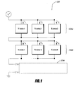
- Figure 1 is a schematic circuit diagram of an example thermal management system 100 comprising a plurality of TE devices in accordance with certain embodiments described herein.
- the TE devices can be TE elements, TE assemblies, and/or TE modules.
- the plurality of TE devices includes a first group 104a of TE devices and a second group 104b of TE devices.
- the TE devices of the first TE group 104a are in parallel electrical communication with one another, and the TE devices of the second TE group 104b are in parallel electrical communication with one another.
- TE device 1, TE device 2, and TE device 3 are in parallel electrical communication with one another and TE device 4, TE device 5, and TE device 6 are in parallel electrical communication with one another.
- the first TE group 104a and the second TE group 104b are in series electrical communication with one another.
- One or more additional TE groups 104c can also be placed in series electrical communication with the first TE group 104a and the second TE group 104b.
- the battery thermal management system 100 can improve overall system cooling and heating reliability.
- the TE devices are configured so as to allow redundancy and eliminate common single point failure mechanisms within each TE group. For example, if TE device 1 fails open such that the TE device 1 is electrically open (e.g., the TE device is unable to pass electrical current), the current is rerouted through TE device 2 and TE device 3 which are electrically connected in parallel with the failed TE device 1. If three or more TE devices are electrically connected together in parallel, more than one TE device could fail open, and the thermal management system 100 would still operate to provide cooling and/or heating.
- TE device 1 fails closed (e.g., the TE device 1 is more electrically conductive than TE device 2 and TE device 3), more of the electrical current will flow through the failed TE device 1 than TE device 2 and TE device 3, and reduce or eliminate the cooling and/or heating of the TE device 2 and TE device 3 in the same parallel electrical connection.
- the TE group 2 that is in series electrical communication with TE group 1 will continue to function and provide heating and/or cooling. Failure of a TE device will degrade performance, but with sufficient numbers of TE devices, and the proper operating conditions, the thermal management system 100 can continue to function, albeit at a reduced heating and/or cooling capability if a TE device fails.
- performance of a thermal management system 100 with one or more failed TE devices can be substantially the same as that of a thermal management system 100 without any failed TE devices.
- Further examples of TE device redundancy are described in U.S. Patent Publication No. 2010/0031987 , which is incorporated herein in its entirety by reference.
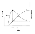
- Figure 2 is a illustrative plot of operating electrical current as a function of the efficiency of energy conversion (COP) and the total thermal output of a TE device (Q c ).
- Points A and A' are near the operating current that optimizes operating efficiency of the TE device (indicated by Point A) so that it will operate near its peak possible efficiency.
- Points B and B' are a second operating current that is at 1.5 times the operating current of Points A and A', and Points C and C' are at a third operating current 3 times the operating current of Points A and A'.
- the dashed lines in Figure 2 illustrate positions of the points relative to each other and relative to the x and y axes.
- a TE device can have a thermal output beyond peak operating efficiency by increasing electrical power even though efficiency may decrease.
- FIG. 3 is a schematic circuit diagram of an example thermal management system 300 that includes a plurality of TE devices in accordance with certain embodiments described herein.
- the thermal management system 300 in Figure 3 also illustrates an example monitoring method to detect failure of a TE device. Diagnosing failure in a TE device of a thermal management system 300 can be measured through monitoring voltages and/or currents of the battery thermal management system 300, either under transient or quasi-steady state conditions. Many other monitoring methods are also possible.
- the electrical configuration of the TE devices of the battery thermal management system 300 illustrated in Figure 3 is similar to that illustrated in Figure 1 .
- the battery thermal management system 300 includes a plurality of TE devices includes a first TE group 304a and a second TE group 304b.
- the TE devices of the first TE group 304a are in parallel electrical communication with one another, and the TE devices of the second TE group 304b are in parallel electrical communication with one another.
- TE device 1, TE device 2, and TE device 3 are in parallel electrical communication with one another and TE device 4, TE device 5, and TE device 6 are in parallel electrical communication with one another.
- the first TE group 304a and the second TE group 304b are in series electrical communication with one another.
- One or more additional TE groups 304c can also be placed in series electrical communication with the first TE group 304a and the second TE group 304b.
- a method of thermally managing a battery system 300 includes providing a battery system comprising at least one battery and a plurality of thermoelectric devices in thermal communication with the at least one battery.
- the plurality of thermoelectric devices includes a first group 304a of thermoelectric devices in series electrical communication with a second group 304b of thermoelectric devices.
- the method includes measuring a first electrical voltage or current of the first group 304a and measuring a second electrical voltage or current of the second group 304b or both the first group 304a and second group 304b together.
- the method further includes monitoring an electrical comparison parameter dependent on the first electrical voltage or current and the second electrical voltage or current.
- the electrical comparison parameter comprises a value of the first electrical voltage or current divided by the second electrical voltage or current.
- the method further includes changing, in response to the electrical comparison parameter, at least one parameter of the battery system.
- the at least one parameter can be, for example, electrical power supplied to the plurality of thermoelectric devices.
- the thermal management system 300 can include two or more voltage and/or current meters for measuring the electrical voltage or current.
- a first meter 306a can measure a first voltage and/or current (V 1 ) across the first group 304a
- a second meter 306b can measure a second voltage and/or current (V 2 ) across the second group 304b.
- a system meter 302 can measure a system voltage and/or current (V + ) across the first TE group 304a, the second group 304b, and the one or more additional TE groups 304c.
- the ratio of V 1 /V 2 , V 1 /V + or V 2 /V + will change if one or more TE devices fail.
- V 1 /V 2 , V 1 /V + , and V 2 /V + would remain constant if one or more TE devices does not fail. Therefore, by monitoring V 1 and V 2 or V + , a failure of a TE device can be detected.
- FIG. 4A illustrates an example battery thermal management system 400 in accordance with certain embodiments described herein.
- a battery thermal management system 400 includes at least one battery 402a-d and at least one thermoelectric device 404 in thermal communication with the at least one battery 402a-d.
- the battery thermal management system 400 can include at least one first conduit 406 that includes at least one inlet 408 configured to allow a first working fluid to enter and flow into the at least one first conduit 406 and into thermal communication with the at least one thermoelectric module 404.
- a heat exchanger 428 can transfer heat between the at least one thermoelectric module 404 and the first working fluid.
- the at least one first conduit 406 also includes at least one outlet 410 configured to allow the first working fluid to exit and flow from the at least one first conduit 406 and away from being in thermal communication with the at least one thermoelectric module 404.
- the battery thermal management system 400 can further include at least one first flow control device 412 which directs the first working fluid through the at least one inlet 408 of the at least one first conduit 406, and at least one second flow control device 414 which directs the first working fluid through the at least one outlet 410 of the at least one first conduit 406.
- the at least one first flow control device 412 and the at least one second flow control device 414 are each separately operable from one another.
- the at least one first flow control device 412 pushes the first working fluid while the at least one second flow control device 414 pulls the first working fluid
- the at least one first flow control device 412 and the at least one second flow control device 414 are in series with one another or are in a push/pull configuration.
- the arrows in Figure 4A illustrate the direction of flow of the working fluid.
- the at least one first control device 412 is positioned at an entrance of the at least one inlet 408 and the at least one second control device 414 is positioned at an exit of the at least one outlet 410.
- the at least one first control device 412 is configured to push the first working fluid through the at least one inlet 408 and the at least one second control device 414 is configured to pull the first working fluid through at least one outlet 410.
- the battery thermal management system 400 further includes a flow path for the first working fluid in which the first working fluid is in thermal communication with the at least one battery. The flow path, in some embodiments, receives the first working fluid from the at least one outlet 408.
- the first working fluid is substantially thermally or electrically isolated from the at least one battery.
- the thermoelectric module 404 can include two sides including a cooler side and a hotter side. The first working fluid can be in thermal communication with only the cooler side or the hotter side, and the first working fluid can be substantially thermally isolated from the other side.
- the battery thermal management system 400 includes at least one second conduit 416 including at least one inlet 418 configured to allow a second working fluid to enter and flow into the at least one second conduit 416 and into thermal communication with the at least one thermoelectric device 404.
- a heat exchanger 426 can transfer heat between the at least one thermoelectric device 404 and the second working fluid.
- the at least one second conduit 416 includes at least one outlet 420 configured to allow the second working fluid to exit and flow from the at least one second conduit 416 and away from being in thermal communication with the at least one thermoelectric device 404.
- the battery thermal management system 400 includes at least one third flow control device 422 which directs the second working fluid through the at least one inlet 418 of the at least one second conduit 416, and at least one fourth flow control device 424 which directs the second working fluid through the at least one outlet 420 of the at least one second conduit 416.
- the at least one third first flow control device 422 and the at least one fourth flow control device 424 are each separately operable from one another.
- the arrows in Figure 4A illustrate the direction of flow of the first working fluid and the second working fluid.
- the first working fluid is substantially thermally isolated from the second working fluid.
- the first working fluid can be in thermal communication with a first side of the TE device 404 and the at least one battery 402a-d
- the second working fluid can be in thermal communication with a second side of the TE device 404 different from the first side.
- the at least one battery 402a-d can be selectively heated or cooled and the first working fluid and second working fluid can be correspondingly heated or cooled.
- the first side of the TE device 404 can be selected to heat or cool the at least one battery 402a-d by heating or cooling the first working fluid and transferring heat between the at least one battery 402a-d and the first working fluid, and the second working fluid can be correspondingly cooled if the first working fluid is heated or heated if the first working fluid is cooled.
- a method of thermally managing a battery thermal management system 400 includes transferring heat between at least one battery 402a-d and at least one thermoelectric device 404 and flowing a working fluid through a fluid conduit 406 in thermal communication with the at least one thermoelectric device 404.
- the method further includes operating at least one first flow control device 412 to direct the working fluid to be in thermal communication with the at least one thermoelectric device 404 and operating at least one second flow control device 414 to direct the working fluid away from being in thermal communication with the at least one thermoelectric device 404.
- the working fluid flows past, along, or around the at least one battery 402a-d and heat is transferred from or to the at least one battery 402a-d.
- the at least one battery 402a-d is in substantially direct thermal communication with the TE device 404 and a working fluid does not transfer heat between the at least one battery 402a-d and the TE device.
- the working fluid is substantially thermally isolated from the at least one battery 402a-d and heat is transferred between the TE device 404 and working fluid.
- the working fluid can transfer waste heat away from the TE device 404.
- Figure 4B illustrates a fluid conduit 450 of a battery thermal management system in accordance with certain embodiments described herein.
- Figure 4B is an example of flow control devices working in parallel while Figure 4A is an example of flow control devices working in series.
- a battery thermal management system includes at least one battery and at least one thermoelectric module 452 in thermal communication with the at least one battery.
- the battery thermal management system further includes at least one fluid conduit 450 configured to allow a working fluid to flow therein and to transfer the working fluid into being in thermal communication with the at least one thermoelectric module 452 or away from being in thermal communication with the at least one thermoelectric module 452.
- At least one first flow control device 454 directs the working fluid through the at least one fluid conduit 450
- at least one second flow control device 456 directs the working fluid through the at least one fluid conduit 450.
- the at least one first flow control device 454 and the at least one second flow control device 456 are each separately operable from one another.
- the battery thermal management system also includes at least one divider portion 458 that is selectively positionable to block the working fluid from flowing between the at least one fluid conduit 450 and a selected one of the at least one first flow control device 454 and the at least one second flow control device 456.
- a divider wall 460 can separate the at least one fluid conduit 450
- a flapper valve 462 can be positioned to block flow of the working fluid through either the first flow control device 454 or the at least one second flow control device 456.
- the dotted line in Figure 4B illustrates the flapper valve 462 blocking the flow through the at least one second flow control device 456, and the arrow illustrates how the flapper valve 462 can rotate to block the flow of the working fluid from flowing through the at least one second flow control device 456.
- the flapper valve 462 prevents back flow of the working fluid through an inoperative flow control device.
- the other arrows in Figure 4B illustrate the direction of flow of the working fluid.
- the at least one divider portion 458 is positionable in multiple positions including: (1) a first position permitting the working fluid to flow between the at least one fluid conduit 450 and the at least one first flow control device 454 and permitting the working fluid to flow between the at least one fluid conduit 450 and the at least one second flow control device 456, (2) a second position permitting the working fluid to flow between the at least one fluid conduit 450 and the at least one first flow control device 454 and blocking the working fluid from flowing between the at least one fluid conduit 450 and the at least one second flow control device 456, and (3) a third position blocking the working fluid from flowing between the at least one fluid conduit 450 and the at least one first flow control device 454 and permitting the working fluid to flow between the at least one fluid conduit 450 and the at least one second flow control device 458.
- the battery thermal management system can include both flow control devices in series and parallel.
- the at least one first flow control device 412 in Figure 4A can include at least two first flow control devices.
- the battery thermal management system 400 can include at least one divider portion that is selectively positionable to block the working fluid from flowing between the at least one first fluid conduit 406 and a selected one of the at least one first flow control devices 412.
- the divider portion separates at least a portion of the at least one inlet or the at least one outlet into at least two fluid channels comprising a first fluid channel and a second fluid channel.
- At least one flow control device of the at least two first flow control devices 412 directs the first working fluid through a first fluid channel, and at least one other flow control device of the at least two first flow control devices directs the first working fluid through a second fluid channel.
- Each of the at least two first flow control devices are each separately operable from one another.
- a method of thermally managing a battery system includes transferring heat between at least one battery and at least one thermoelectric device 452 and flowing a working fluid through a fluid conduit 450 in thermal communication with at least one thermoelectric device 452. The method further includes directing the working fluid through the fluid conduit 450 using at least one first flow control device 454 and at least one second flow control device 456 and selectively inhibiting flow of the working fluid through a selected one of the at least one first flow control device 454 and the at least one second flow control device 456.
- the battery thermal management system includes a plurality of power lines and/or redundancy with the power source or supply.
- the power supply can have several power conversion phases and energy filtering and/or storage components.
- Other methods of providing electrical power redundancy may also be provided. While performance such as ripple or drop out may occur as the result of a single failure, cooling or heating can continue to be provided.
- the TE device is put in close proximity to the battery.
- TE device may be attached, coupled, or integrated with the battery or a battery case.
- the cooling or heating side of a TE device can be advantageously positioned as close to the battery as possible.
- the cooling or heating power that may be lost through ducts or insulation can directly condition the system. Conditioning can include transferring heat to the battery to increase the temperature of the battery or transferring heat from the battery to decrease the temperature of the battery.
- the thermal power generated that leaks out of at least a portion of the ducts, conduits, or other mechanisms that direct a conditioned working fluid often still can be at least partially utilized.
- the conditioning surfaces such as ducts, tubes, etc. are positioned generally toward the working fluid, battery, or volume to be cooled, and the heat rejection side generally away from the conditioned surfaces and area.
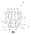
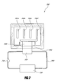
- FIG. 7 illustrates an example battery thermal management system 700 that includes at least one conduit 760 (e.g. fluid circuit) in accordance with certain embodiments described herein.
- the battery thermal management system 700 includes at least one battery 702a-d and at least one thermoelectric device 704 in thermal communication with the at least one battery 702a-d.
- the battery thermal management system 700 includes at least one flow control device 740 such as a fluid pump.
- the at least one flow control device 740 circulates the working fluid through the at least one conduit 760.
- the working fluid is re-circulated through the at least one conduit 760.
- the working fluid may flow into thermal communication with the at least one thermoelectric device 704, and the working fluid may flow away from being in thermal communication with the at least one thermoelectric device 704.
- At least one heat exchanger 726 may be in thermal communication with the at least one thermoelectric device 704.
- the working fluid may flow into thermal communication with the at least one heat exchanger 726 and the working fluid may flow away from being in thermal communication with the at least one heat exchanger 726.
- the same working fluid may flow into and away from being in thermal communication with the at least one thermoelectric device 704 more than once.
- the at least one conduit 760 can be a fluid loop.
- the battery thermal management system 700 includes a fluid reservoir or source 750 fluidly coupled with the at least one conduit 760.
- the fluid reservoir or source 750 may heat or cool the working fluid.
- the fluid reservoir or source 750 can be connected to other sources of heat such as an engine powertrain fluid to provide further heat to the at least one battery 702a-d.
- the fluid reservoir or source 750 can include a radiator such as a vehicle chassis or an auxiliary radiator to reject heat from the at least one battery 702a-d through the at least one TE device 704.
- the working fluid can be any type of fluid such as liquid, gas, or multipurpose solid-liquid convection medium.
- the working fluid comprises a mixture of water and glycol.
- a liquid working fluid may have a greater thermal capacity than a gas working fluid, which can result in greater efficiency for the TE device 704.
- many heat exchangers with fins, etc. have a higher thermal coefficient of performance or a higher heat transfer rate with the working fluid when the working fluid is a liquid than when the working fluid is a gas (e.g., air).
- a higher thermal coefficient of performance can reduce the temperature drop across the interface between the working fluid and the heat exchanger 726.
- the total temperature drop between the TE device 704 and the working fluid can be reduced.
- a lower temperature drop can result in higher efficiency for the TE device 704 and/or higher temperature differential across the TE device 704.
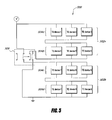
- FIG. 5 is a schematic circuit diagram of an example thermal management system 500 comprising a plurality of TE devices configured to change thermal power output by changing the electrical configuration of the TE devices in accordance with certain embodiments described herein. For example, under extreme ambient heat (or cold), it may be desirable to increase the current through the TE devices to increase cooling (or heating) thermal power output.
- the TE devices can be TE elements, TE assemblies, or TE modules.
- At battery thermal management system 500 includes at least one battery and a plurality of thermoelectric assemblies 502a, 502b in thermal communication with the at least one battery.
- Each thermoelectric assembly 502a, 502b includes a plurality of thermoelectric devices.
- a first thermoelectric assembly 502a of the plurality of thermoelectric assemblies is in electrical communication with a second thermoelectric assembly 502b of the plurality of thermoelectric assemblies.
- a circuit 506 is in electrical communication with the first thermoelectric assembly 502a and the second thermoelectric assembly 502b.
- the circuit 506 can be configured to be selectively switchable to place the first thermoelectric assembly 502a and the second thermoelectric assembly 502b either in series electrical communication or parallel electrical communication with one another.
- thermoelectric elements of the first thermoelectric assembly 502a can be in series electrical communication and/or in parallel electrical communication with one another
- at least some of the plurality of thermoelectric elements of the second thermoelectric assembly 502b can be in series electrical communication and/or parallel electrical communication with one another
- the first thermoelectric assembly 502a can include a first plurality of TE groups 504a, 504b
- the second thermoelectric assembly 502b can include a second plurality of TE groups 504c, 504d.
- a first TE group 504a of TE devices are in parallel electrical communication with one another
- a second TE group 504b of TE devices are in parallel electrical communication with one another
- a third TE group 504c of TE devices are in parallel electrical communication with one another
- a fourth TE group 504d of TE devices are in parallel electrical communication with one another.
- the first TE group 504a is in parallel electrical communication with the second TE group 504b
- the third group 504c is in parallel electrical communication with the fourth TE group 504d.
- thermoelectric assembly 502a can be configured to be selectively switchable to place the first thermoelectric assembly 502a and the second thermoelectric assembly 502b either in series electrical communication or parallel electrical communication with one another.
- the solid lines in the circuit 506 of Figure 5 illustrate a first circuit position wherein the first TE group 504a, the second TE group 504b, the third TE group 504c, and the fourth TE group 504d are in series electrical communication with one another.
- the dotted lines in the circuit 506 of Figure 5 illustrate a second circuit position wherein the first TE group 504a is in series electrical communication with the second TE group 504b, the third TE group 504c is in series electrical communication with the fourth TE group 504d, and the first thermoelectric assembly 502a (e.g., the first TE group 504a and the second TE group 504b) is in parallel electrical communication with the second thermoelectric assembly 502b (e.g., the third TE group 504c and the second TE group 504d).
- a method of thermally managing a battery system 500 includes providing a battery system including at least one battery and a plurality of thermoelectric assemblies 502a, 502b in thermal communication with the at least one battery. The method further includes measuring at least one parameter of the battery system and switching, in response to the at least one parameter, a first thermoelectric assembly 502a of the plurality of thermoelectric assemblies between being in parallel or series electrical communication with a second thermoelectric assembly 502b of the plurality of thermoelectric assemblies.
- the at least one parameter can, for example, include temperature of the at least one battery and/or the battery system. Additional parameters are discussed in the following sections.
- the plurality of thermoelectric assemblies are selectively operable to either heat or cool the at least one battery.
- the circuit 506 may also be selectively switchable to adjust current flow through the first thermoelectric assembly 502a and the second thermoelectric assembly 502b.
- voltage of the circuit 502 can be altered to cause more or less current to flow through the TE devices in order to modify heat pumping capacity of the TE devices.
- the performance of the BTMS can be altered by, for example, altering fan and/or pump operation to change working fluid flow conditions such as flow rate and/or flow paths.
- the BTMS can further include a controller to control the circuit 502, flow control devices, etc. of the BTMS.
- the controller may be integrated with the BTMS or may be an external controller.
- Thermal management can be important to the proper operation and life of a battery or battery array, so monitoring temperatures and other parameters to determine the state of operation of the BTMS can be advantageous. Several conditions can also be monitored simultaneously and/or periodically or at various times to assure proper function and address operational discrepancies. Monitoring sensors and devices can be incorporated into the TE devices, fans and/or pumps the electrical circuitry and other parts of the system to provide useful information.
- Figure 6 illustrates examples of a plurality of monitoring systems 630a-d and their locations in a BTMS 600 in accordance with certain embodiments described herein.
- a TE device 604 can include one or more monitoring systems 630a-d including TE device monitoring systems 630a, battery monitoring systems 630b, working fluid monitoring systems 630c, and flow control device monitoring systems 630d that can measure at least one parameter.
- the monitoring systems 630a-d can be integrated within, on a surface of, neighboring, or within proximity to measure the at least one parameter of the TE device 604, battery 602a-d, working fluid, flow control device 612, etc.
- components such as fans, circuit elements, battery parts, batteries, components of a battery, battery arrays and/or BTMS can include monitoring systems 630a-d.
- a monitoring system 630a-d can include one or more temperature sensors. Temperature sensors can include thermistors, positive temperature coefficient-thermal cutoffs, thermocouples and other temperature sensing and temperature activated devices. Temperatures that can be monitored can include, for example, working fluid, inlet fluid temperatures, conditioned fluid temperatures, temperature differentials between fluid inlets and outlets, temperature between the conditioning side and the heat rejection side, fluid control device (e.g., pump or fan) temperatures. Furthermore, multiple measurements at several locations and any other combination of temperature measurements may be made.
- fluid control device speeds, fluid control device voltages and/or currents, fluid flow rates at one or multiple locations, emissions of fluids from the battery, battery array or any other device, fluid velocities, battery voltages and/or currents, battery or battery dimensions and/or dimensional change can be monitored.
- at least one monitoring system can include circuit sensors to monitor electrical communication of circuits and/or TE devices 604.
- Monitoring systems can also provide a signal or be in communication with a control device.
- the control device may measure the at least one parameter that is monitored, and the control device may, in response to the at least one parameter, cause at least one component of the BTMS to change.
- the control device may apply an algorithm to the measured parameter to determine what response, if any, the control device may apply to a component of the BTMS.
- Control devices can include devices that acquire sensor data, perform calculations based on the sensor data, and cause at least one component of the BTMS to change such as valves, blower speed controllers and other devices to actuate or reduce/increase flow rate, etc., and parametric controllers.
- At least one parameter can be monitored to determine the exposure the battery, battery array or BTMS may have experienced and any other operating history of the BTMS that may be useful.
- the monitoring can be done for warranty, determining charge cycle (e.g., optimizing speed of charge), state of operation, safety, optimizing performance, increasing longevity, establishing operational history, indicating failure, modifying battery charge schedules based on measured values, indicating impending degradation of performance and any other diagnostic measurements.
- the BTMS may contain control, communication, computational, storage and/or processing capabilities to act upon the information collected by components of the BTMS and/or other systems in communication with the BTMS and communicate results of information processed by the BTMS and/or other systems.
- the BTMS may contain electronic signal processing hardware, input/output devices, permanent recording hardware or any other useful electronic or other signal processing equipment.
- the system may have the capacity to take actions, send signals, receive signals, store information, perform logic functions, control temperatures, fan and/or pump, TE, and any other subsystem function, modify operation and/or perform any other function to manage battery or battery array operation.
Claims (16)
- Système de gestion thermique de batterie comprenant :au moins une batterie ;une pluralité d'ensembles thermoélectriques en communication thermique avec ladite au moins une batterie, chaque ensemble thermoélectrique comprenant une pluralité d'éléments thermoélectriques, dans lequel un premier ensemble thermoélectrique de la pluralité d'ensembles thermoélectriques est en communication électrique avec un deuxième ensemble thermoélectrique de la pluralité d'ensembles thermoélectriques ; etun circuit en communication électrique avec le premier ensemble thermoélectrique et le deuxième ensemble thermoélectrique, le circuit étant configuré pour pouvoir être commuté de manière sélective pour placer le premier ensemble thermoélectrique et le deuxième ensemble thermoélectrique soit en communication électrique série, soit en communication électrique parallèle l'un avec l'autre.
- Système de gestion thermique de batterie selon la revendication 1, dans lequel au moins certains de la pluralité d'éléments thermoélectriques du premier ensemble thermoélectrique sont en communication électrique série les uns avec les autres et au moins certains de la pluralité d'éléments thermoélectriques du deuxième ensemble thermoélectrique sont en communication électrique série les uns avec les autres.
- Système de gestion thermique de batterie selon la revendication 1 ou la revendication 2, dans lequel la pluralité d'ensembles thermoélectriques peuvent être utilisés de manière sélective soit pour chauffer, soit pour refroidir ladite au moins une batterie.
- Système de gestion thermique de batterie selon l'une quelconque des revendications 1 à 3, dans lequel le circuit peut être commuté de manière sélective pour ajuster la circulation de courant à travers le premier ensemble thermoélectrique et le deuxième ensemble thermoélectrique.
- Système de gestion thermique de batterie selon l'une quelconque des revendications 1 à 4, dans lequel au moins certains de la pluralité d'éléments thermoélectriques du premier ensemble thermoélectrique sont en communication électrique parallèle ou série les uns avec les autres.
- Système de gestion thermique de batterie selon l'une quelconque des revendications 1 à 5, comprenant en outre un contrôleur configuré pour commander le circuit.
- Système de gestion thermique de batterie selon l'une quelconque des revendications 1 à 6, comprenant en outre un dispositif de surveillance configuré pour surveiller au moins un paramètre.
- Système de gestion thermique de batterie selon la revendication 7, dans lequel ledit au moins un paramètre comprend une température de ladite au moins une batterie.
- Système de gestion thermique de batterie selon l'une quelconque des revendications 1 à 8,
dans lequel le premier ensemble thermoélectrique comprend au moins un premier groupe de dispositifs thermoélectriques et un deuxième groupe de dispositifs thermoélectriques, dans lequel les dispositifs thermoélectriques du premier groupe sont en communication électrique parallèle les uns avec les autres et les dispositifs thermoélectriques du deuxième groupe sont en communication électrique parallèle les uns avec les autres,
dans lequel le deuxième ensemble thermoélectrique comprend au moins un troisième groupe de dispositifs thermoélectriques et un quatrième groupe de dispositifs thermoélectriques, dans lequel les dispositifs thermoélectriques du troisième groupe sont en communication électrique parallèle les uns avec les autres et les dispositifs thermoélectriques du quatrième groupe sont en communication électrique parallèle les uns avec les autres, et
dans lequel le premier groupe de dispositifs thermoélectriques est en communication électrique série avec le deuxième groupe de dispositifs thermoélectriques et le troisième groupe de dispositifs thermoélectriques est en communication électrique série avec le quatrième groupe de dispositifs thermoélectriques. - Procédé de gestion thermique d'un système de batterie, comprenant :la fourniture d'un système de batterie comprenant au moins une batterie et une pluralité d'ensembles thermoélectriques en communication thermique avec ladite au moins une batterie ;la mesure d'au moins un paramètre du système de batterie ; etla commutation, en réponse au dit au moins un paramètre, d'un premier ensemble thermoélectrique de la pluralité d'ensembles thermoélectriques entre une communication électrique parallèle ou une communication électrique série avec un deuxième ensemble thermoélectrique de la pluralité d'ensembles thermoélectriques.
- Procédé selon la revendication 10, dans lequel ledit au moins un paramètre comprend une température de ladite au moins une batterie.
- Procédé selon la revendication 10 ou la revendication 11, dans lequel ledit au moins un paramètre comprend une température d'au moins l'un de la pluralité d'ensembles thermoélectriques.
- Procédé selon l'une quelconque des revendications 10 à 12, dans lequel ledit au moins un paramètre indique si un élément thermoélectrique de la pluralité d'ensembles thermoélectriques est défaillant.
- Procédé selon l'une quelconque des revendications 10 à 13, dans lequel le premier ensemble thermoélectrique comprend une pluralité d'éléments thermoélectriques, au moins certains de la pluralité d'éléments thermoélectriques du premier ensemble thermoélectrique étant en communication électrique parallèle ou série les uns avec les autres.
- Procédé selon l'une quelconque des revendications 10 à 14, dans lequel la pluralité d'ensembles thermoélectriques peuvent être utilisés de manière sélective soit pour chauffer, soit pour refroidir ladite au moins une batterie.
- Procédé selon l'une quelconque des revendications 10 à 15, comprenant en outre :la circulation d'un fluide de travail à travers un conduit de fluide en communication thermique avec au moins l'un de la pluralité d'ensembles thermoélectriques ;la mise en oeuvre d'au moins un premier dispositif de commande de circulation pour diriger le fluide de travail pour qu'il soit en communication thermique avec ledit au moins un de la pluralité d'ensembles thermoélectriques ; etla mise en oeuvre d'au moins un deuxième dispositif de commande de circulation séparément de la mise en oeuvre dudit au moins un premier dispositif de commande de circulation pour diriger le fluide de travail pour qu'il ne soit plus en communication thermique avec ledit au moins un de la pluralité d'ensembles thermoélectriques.
Applications Claiming Priority (2)
| Application Number | Priority Date | Filing Date | Title |
|---|---|---|---|
| US17932609P | 2009-05-18 | 2009-05-18 | |
| PCT/US2010/035321 WO2010135371A2 (fr) | 2009-05-18 | 2010-05-18 | Système de gestion thermique de batterie |
Publications (2)
| Publication Number | Publication Date |
|---|---|
| EP2433321A2 EP2433321A2 (fr) | 2012-03-28 |
| EP2433321B1 true EP2433321B1 (fr) | 2014-10-22 |
Family
ID=42320084
Family Applications (1)
| Application Number | Title | Priority Date | Filing Date |
|---|---|---|---|
| EP10721588.1A Not-in-force EP2433321B1 (fr) | 2009-05-18 | 2010-05-18 | Système de gestion thermique de batterie |
Country Status (8)
| Country | Link |
|---|---|
| US (6) | US8974942B2 (fr) |
| EP (1) | EP2433321B1 (fr) |
| JP (1) | JP5496324B2 (fr) |
| KR (4) | KR101979955B1 (fr) |
| CN (2) | CN104538697B (fr) |
| MX (1) | MX2011012238A (fr) |
| RU (1) | RU2011143856A (fr) |
| WO (1) | WO2010135371A2 (fr) |
Families Citing this family (74)
| Publication number | Priority date | Publication date | Assignee | Title |
|---|---|---|---|---|
| US7273981B2 (en) * | 2001-02-09 | 2007-09-25 | Bsst, Llc. | Thermoelectric power generation systems |
| JP2004537708A (ja) | 2001-08-07 | 2004-12-16 | ビーエスエスティー エルエルシー | 熱電気式個人用環境調整機器 |
| US20110209740A1 (en) * | 2002-08-23 | 2011-09-01 | Bsst, Llc | High capacity thermoelectric temperature control systems |
| US7380586B2 (en) | 2004-05-10 | 2008-06-03 | Bsst Llc | Climate control system for hybrid vehicles using thermoelectric devices |
| US7743614B2 (en) | 2005-04-08 | 2010-06-29 | Bsst Llc | Thermoelectric-based heating and cooling system |
| US8783397B2 (en) | 2005-07-19 | 2014-07-22 | Bsst Llc | Energy management system for a hybrid-electric vehicle |
| US20100155018A1 (en) | 2008-12-19 | 2010-06-24 | Lakhi Nandlal Goenka | Hvac system for a hybrid vehicle |
| US7779639B2 (en) | 2006-08-02 | 2010-08-24 | Bsst Llc | HVAC system for hybrid vehicles using thermoelectric devices |
| WO2008148042A2 (fr) | 2007-05-25 | 2008-12-04 | Bsst Llc | Système et procédé pour le chauffage et le refroidissement thermoélectrique distribués |
| WO2010048575A1 (fr) | 2008-10-23 | 2010-04-29 | Bsst Llc | Système hvac à modes multiples à dispositif thermoélectrique |
| US9555686B2 (en) | 2008-10-23 | 2017-01-31 | Gentherm Incorporated | Temperature control systems with thermoelectric devices |
| US9038400B2 (en) | 2009-05-18 | 2015-05-26 | Gentherm Incorporated | Temperature control system with thermoelectric device |
| US9447994B2 (en) | 2008-10-23 | 2016-09-20 | Gentherm Incorporated | Temperature control systems with thermoelectric devices |
| RU2011143856A (ru) | 2009-05-18 | 2013-06-27 | БиЭсЭсТи ЭлЭлСи | Система термоуправления батареей |
| WO2010148224A2 (fr) | 2009-06-18 | 2010-12-23 | Jason Fuhr | Module de batterie ayant un plateau porte-éléments avec caractéristiques de gestion thermique |
| WO2011138156A1 (fr) | 2010-05-07 | 2011-11-10 | Siemens Aktiengesellschaft | Accumulateur d'énergie électrique et dispositif de refroidissement |
| US20120203421A1 (en) * | 2011-02-07 | 2012-08-09 | GM Global Technology Operations LLC | Data association for vehicles |
| DE102011004721A1 (de) * | 2011-02-25 | 2012-08-30 | Behr Gmbh & Co. Kg | Temperierungsvorrichtung und Verfahren zur Temperierung eines Energiespeichers |
| US9553460B2 (en) * | 2011-03-31 | 2017-01-24 | Elite Power Solutions Llc | Wireless battery management system |
| US8722222B2 (en) | 2011-07-11 | 2014-05-13 | Gentherm Incorporated | Thermoelectric-based thermal management of electrical devices |
| JP2013025948A (ja) * | 2011-07-19 | 2013-02-04 | Toyota Industries Corp | 電池モジュール |
| JP5365715B2 (ja) * | 2012-03-12 | 2013-12-11 | 株式会社豊田自動織機 | 電池パック |
| US9415700B2 (en) * | 2012-09-04 | 2016-08-16 | GM Global Technology Operations LLC | Battery thermal system and diagnostic method |
| KR101877996B1 (ko) * | 2012-09-07 | 2018-07-16 | 현대자동차주식회사 | 배터리 시스템 |
| KR101371739B1 (ko) * | 2012-09-07 | 2014-03-12 | 기아자동차(주) | 배터리 시스템 |
| KR101355616B1 (ko) * | 2012-10-23 | 2014-01-27 | 기아자동차주식회사 | 배터리 관리시스템 및 관리방법 |
| DE102012224486A1 (de) * | 2012-12-28 | 2014-04-10 | Behr Gmbh & Co. Kg | Wärmeübertrager |
| WO2014110524A1 (fr) | 2013-01-14 | 2014-07-17 | Gentherm Incorporated | Gestion thermique à base thermoélectrique de dispositifs électriques |
| KR102253247B1 (ko) | 2013-01-30 | 2021-05-17 | 젠썸 인코포레이티드 | 열전-기반 열 관리 시스템 |
| CN103219831A (zh) * | 2013-03-22 | 2013-07-24 | 天津市松正电动汽车技术股份有限公司 | 气冷电机及新能源汽车电池加热装置 |
| JP6024562B2 (ja) * | 2013-03-28 | 2016-11-16 | トヨタ自動車株式会社 | バッテリの温度調節システム |
| US9799933B2 (en) | 2013-08-28 | 2017-10-24 | Robert Bosch Gmbh | Solid state battery with integrated rate booster |
| CN106030898B (zh) | 2013-10-29 | 2019-04-05 | 詹思姆公司 | 利用热电学的电池热管理 |
| US20160161959A1 (en) * | 2014-06-12 | 2016-06-09 | Mediatek Inc. | Thermal management method and electronic system with thermal management mechanism |
| WO2016029678A1 (fr) * | 2014-08-29 | 2016-03-03 | 青岛海尔空调器有限总公司 | Unité intérieure de climatiseur à montage mural |
| DE112015004176T5 (de) | 2014-09-12 | 2017-06-14 | Gentherm Incorporated | Graphit einschließende thermoelektrische und/oder ohmsche Wärmemanagementsysteme und Verfahren |
| KR101829093B1 (ko) * | 2014-10-22 | 2018-03-29 | 주식회사 엘지화학 | 배터리 시스템의 냉각 공기 흐름 제어 시스템 및 방법 |
| CN105633484A (zh) * | 2014-10-31 | 2016-06-01 | 中华汽车工业股份有限公司 | 电动车电池温度管理系统 |
| US10581251B2 (en) * | 2014-12-18 | 2020-03-03 | Fca Us Llc | Battery pack active thermal management system |
| WO2016100697A1 (fr) | 2014-12-19 | 2016-06-23 | Gentherm Incorporated | Systèmes et procédés de conditionnement thermique pour des régions de véhicule |
| US9627725B2 (en) | 2015-04-28 | 2017-04-18 | Lg Chem, Ltd. | Battery pack |
| US10290911B2 (en) * | 2015-05-18 | 2019-05-14 | Toyota Motor Engineering & Manufacturing North America, Inc. | Cooling loops and vehicles incorporating the same |
| KR102017275B1 (ko) | 2015-06-10 | 2019-09-02 | 젠썸 인코포레이티드 | 일체형 냉각판 어셈블리를 가진 자동차 전지 열전 모듈 및 그 조립 방법 |
| WO2017015826A1 (fr) | 2015-07-27 | 2017-02-02 | 宁德时代新能源科技股份有限公司 | Module de gestion de chaleur de groupe de batteries |
| JP2017045970A (ja) * | 2015-08-29 | 2017-03-02 | 京セラ株式会社 | 熱電モジュール |
| WO2017065847A1 (fr) | 2015-10-14 | 2017-04-20 | Gentherm Incorporated | Systèmes et procédés de commande de conditionnement thermique de régions de véhicule |
| US10471803B2 (en) * | 2016-01-27 | 2019-11-12 | Ford Global Technologies, Llc | Systems and methods for thermal battery control |
| US10361577B2 (en) | 2016-04-05 | 2019-07-23 | Adam Gleason | Battery charging and cooling apparatus |
| US10714956B2 (en) | 2016-04-05 | 2020-07-14 | Adam Gleason | Apparatus, system, and method for battery charging |
| CN106711537A (zh) * | 2016-11-16 | 2017-05-24 | 浙江超威创元实业有限公司 | 内部结构配合热管散热方式的锂电池 |
| GB2556881A (en) * | 2016-11-23 | 2018-06-13 | Ford Global Tech Llc | A method of adaptively controlling an electrical system having a lithium-ion battery |
| WO2018210363A1 (fr) * | 2017-05-17 | 2018-11-22 | Gentherm Gmbh | Appareil de gestion de température pour batteries de véhicules |
| KR20200051833A (ko) * | 2017-10-06 | 2020-05-13 | 노마 유.에스. 홀딩 엘엘씨 | 배터리 열 관리용 매니폴드 세그먼트 및 그 어셈블리 |
| CN109980313A (zh) * | 2017-12-27 | 2019-07-05 | 河南森源重工有限公司 | 一种电池组的热管理控制方法及系统 |
| DE102018205363A1 (de) * | 2018-04-10 | 2019-10-10 | Bayerische Motoren Werke Aktiengesellschaft | Vorrichtung zur Temperierung eines elektrischen Energiespeichers |
| US10873116B2 (en) * | 2018-05-18 | 2020-12-22 | Lee Fei Chen | Charging device having thermoelectric module |
| EP3588667A1 (fr) * | 2018-06-25 | 2020-01-01 | APR Technologies AB | Refroidissement par immersion d'un dispositif de batterie |
| CN109119726A (zh) * | 2018-09-27 | 2019-01-01 | 蔚来汽车有限公司 | 电池包的温度控制装置和方法 |
| US11152557B2 (en) | 2019-02-20 | 2021-10-19 | Gentherm Incorporated | Thermoelectric module with integrated printed circuit board |
| US11670813B2 (en) | 2019-04-01 | 2023-06-06 | Applied Thermoelectric Solutions, LLC | Electrically insulative and thermally conductive parallel battery cooling and temperature control system |
| DE102019003534A1 (de) * | 2019-05-21 | 2020-11-26 | Gentherm Gmbh | Temperiereinrichtung für einen Energiespeicher |
| CN110576746A (zh) * | 2019-09-04 | 2019-12-17 | 陕西法士特齿轮有限责任公司 | 一种纯电动车能量管理方法 |
| KR102287330B1 (ko) | 2019-11-15 | 2021-08-06 | 삼성에스디아이 주식회사 | 팬 고장 검출 장치 |
| FR3106937A1 (fr) * | 2020-02-05 | 2021-08-06 | Valeo Systemes Thermiques | Dispositif de régulation de température d’un élément électrique susceptible de dégager de la chaleur en fonctionnement et pack-batterie comprenant un tel dispositif |
| US11592210B2 (en) | 2020-06-08 | 2023-02-28 | Max Moskowitz | System and method for providing heated water to sabbath observers |
| KR20220150004A (ko) * | 2021-05-03 | 2022-11-10 | 에스케이온 주식회사 | 이차 전지 |
| CN113381096B (zh) * | 2021-06-09 | 2022-10-14 | 上海理工大学 | 基于冷却路径的实时优化电池热管理系统 |
| KR102463150B1 (ko) * | 2022-02-09 | 2022-11-08 | (주)프라즈마 사이언스 | 물리적 안전성 및 화학적 안전성을 강화시키기 위한 배터리 모듈 및 배터리 모듈 관리 시스템 |
| WO2023183802A2 (fr) * | 2022-03-21 | 2023-09-28 | Georgia Tech Research Corporation | Systèmes et procédés de gestion thermique d'une batterie |
| EP4276974A1 (fr) * | 2022-05-09 | 2023-11-15 | Volvo Truck Corporation | Système de refroidissement pour une ou plusieurs cellules de batterie d'une batterie électrique |
| EP4292840A2 (fr) | 2022-06-16 | 2023-12-20 | Voss Automotive GmbH | Dispositif de gestion thermique et véhicule doté d'au moins un tel dispositif de gestion thermique |
| DE102022002190A1 (de) | 2022-06-16 | 2023-12-21 | Voss Automotive Gmbh | Thermomanagementanordnung und Fahrzeug mit zumindest einer solchen Thermomanagementanordnung |
| DE102022002189A1 (de) | 2022-06-16 | 2023-12-21 | Voss Automotive Gmbh | Thermomanagementanordnung und Fahrzeug mit zumindest einer solchen Thermomanagementanordnung |
| EP4292841A2 (fr) | 2022-06-16 | 2023-12-20 | Voss Automotive GmbH | Dispositif de gestion thermique et véhicule doté d'au moins un tel dispositif de gestion thermique |
Family Cites Families (425)
| Publication number | Priority date | Publication date | Assignee | Title |
|---|---|---|---|---|
| US413136A (en) | 1889-10-15 | dewey | ||
| GB231192A (en) | 1924-03-21 | 1926-05-06 | Alice Sandberg | Improvements in regenerative preheaters for air or other media |
| US2363168A (en) | 1942-10-08 | 1944-11-21 | Eaton Mfg Co | Heater |
| US2519241A (en) | 1946-07-05 | 1950-08-15 | Eaton Mfg Co | Thermoelectric generator and burner therefor |
| US2499901A (en) | 1946-08-31 | 1950-03-07 | Brown Fintube Co | Fin tube assembly |
| US2944404A (en) | 1957-04-29 | 1960-07-12 | Minnesota Mining & Mfg | Thermoelectric dehumidifying apparatus |
| US2997514A (en) | 1958-03-11 | 1961-08-22 | Whirlpool Co | Refrigerating apparatus |
| US2949014A (en) | 1958-06-02 | 1960-08-16 | Whirlpool Co | Thermoelectric air conditioning apparatus |
| US2984077A (en) | 1958-10-24 | 1961-05-16 | Collins Radio Co | Method of using the peltier effect for cooling equipment |
| US3085405A (en) | 1961-04-06 | 1963-04-16 | Westinghouse Electric Corp | Thermoelectric air conditioning apparatus for a protective garment |
| US3136577A (en) | 1961-08-02 | 1964-06-09 | Stevenson P Clark | Seat temperature regulator |
| DE1301454B (de) | 1962-03-07 | 1969-08-21 | Eigner Otto | Raumkuehlgeraet |
| GB1040485A (en) | 1962-06-28 | 1966-08-24 | Licentia Gmbh | Improvements relating to refrigerating equipment |
| US3125860A (en) | 1962-07-12 | 1964-03-24 | Thermoelectric cooling system | |
| US3137142A (en) | 1962-09-24 | 1964-06-16 | Borg Warner | Heat transfer system as it pertains to thermoelectrics |
| US3138934A (en) | 1962-11-19 | 1964-06-30 | Kysor Industrial Corp | Thermoelectric heating and cooling system for vehicles |
| US3196620A (en) | 1964-02-10 | 1965-07-27 | Thore M Elfving | Thermoelectric cooling system |
| US3212275A (en) | 1964-08-20 | 1965-10-19 | American Radiator & Standard | Thermoelectric heat pump |
| US3527621A (en) | 1964-10-13 | 1970-09-08 | Borg Warner | Thermoelectric assembly |
| US3213630A (en) | 1964-12-18 | 1965-10-26 | Westinghouse Electric Corp | Thermoelectric apparatus |
| US3252504A (en) | 1964-12-30 | 1966-05-24 | Borg Warner | Thermoelectric air conditioning systems |
| US3236056A (en) | 1965-01-11 | 1966-02-22 | Edward L Phillips | Apparatus for cooling automobiles and the like |
| US3391727A (en) | 1966-11-14 | 1968-07-09 | Ford Motor Co | Disc type rotary heat exchanger |
| US3561224A (en) | 1967-06-07 | 1971-02-09 | Trw Inc | Thermoelectric temperature controller |
| US3554809A (en) | 1967-12-18 | 1971-01-12 | Gen Electric | Process and apparatus for distributing fluid inerts with respect to the electrodes of a fuel battery |
| DE1944453B2 (de) | 1969-09-02 | 1970-11-19 | Buderus Eisenwerk | Peltierbatterie mit Waermeaustauscher |
| SE337227B (fr) | 1969-11-24 | 1971-08-02 | Asea Ab | |
| DE1963023A1 (de) | 1969-12-10 | 1971-06-16 | Siemens Ag | Thermoelektrische Vorrichtung |
| US3599437A (en) | 1970-03-03 | 1971-08-17 | Us Air Force | Thermoelectric cooling device |
| DE2058280A1 (de) | 1970-11-26 | 1972-06-08 | Sueddeutsche Kuehler Behr | Kreislauf zum Heizen und/oder Kuehlen von Raeumen,insbesondere Fahrzeugen |
| BE791951A (fr) | 1971-12-10 | 1973-03-16 | Int Promotion Eng Sa | Perfectionnements aux moyens de production de froid et applications |
| US3885126A (en) | 1972-06-07 | 1975-05-20 | Nissan Motor | Electric heat accumulator unit |
| US3817043A (en) | 1972-12-07 | 1974-06-18 | Petronilo C Constantino & Ass | Automobile air conditioning system employing thermoelectric devices |
| DE2319155A1 (de) | 1973-04-16 | 1974-10-31 | Daimler Benz Ag | Emissionsfreie beheizung von fahrzeugen mit hybridantrieb |
| US4051691A (en) | 1973-12-10 | 1977-10-04 | Dawkins Claude W | Air conditioning apparatus |
| FR2315771A1 (fr) | 1975-06-27 | 1977-01-21 | Air Ind | Perfectionnements apportes aux installations thermo-electriques |
| US4065936A (en) | 1976-06-16 | 1978-01-03 | Borg-Warner Corporation | Counter-flow thermoelectric heat pump with discrete sections |
| US4193271A (en) | 1977-07-07 | 1980-03-18 | Honigsbaum Richard F | Air conditioning system having controllably coupled thermal storage capability |
| US4280330A (en) | 1977-09-19 | 1981-07-28 | Verdell Harris | Vehicle heating and cooling system |
| JPS5618231Y2 (fr) | 1978-09-08 | 1981-04-28 | ||
| US4229687A (en) | 1979-05-07 | 1980-10-21 | Utah Research & Development Corporation | Temperature maintained battery system |
| JPS5618231A (en) | 1979-07-25 | 1981-02-20 | Masahiro Morita | Cool sleep system |
| US4324845A (en) | 1980-06-30 | 1982-04-13 | Communications Satellite Corp. | Metal-oxide-hydrogen cell with variable conductant heat pipe |
| US4314008A (en) | 1980-08-22 | 1982-02-02 | General Electric Company | Thermoelectric temperature stabilized battery system |
| IL63115A (en) | 1981-06-18 | 1989-09-10 | Ormat Turbines | Method and apparatus for controlling temperature and humidity within an enclosure |
| US4489568A (en) * | 1982-02-03 | 1984-12-25 | Snyder General Corporation | Ground water heat pump system |
| US4448157A (en) | 1982-03-08 | 1984-05-15 | Eckstein Robert J | Auxiliary power unit for vehicles |
| US4444851A (en) | 1982-06-28 | 1984-04-24 | Energy Research Corporation | Fuel cell stack |
| US4531379A (en) | 1983-10-14 | 1985-07-30 | Diefenthaler Jr Robert E | Auxiliary power system for vehicle air conditioner and heater |
| US4494380A (en) | 1984-04-19 | 1985-01-22 | Bilan, Inc. | Thermoelectric cooling device and gas analyzer |
| DE3519044A1 (de) | 1984-05-28 | 1985-11-28 | Mitsubishi Denki K.K., Tokio/Tokyo | Kuehler fuer kraftfahrttechnische verwendung und kraftfahrzeug-klimaanlage |
| JPS60259517A (ja) | 1984-06-04 | 1985-12-21 | Diesel Kiki Co Ltd | 自動車用空気調和装置 |
| US4665707A (en) | 1985-08-26 | 1987-05-19 | Hamilton A C | Protection system for electronic apparatus |
| IT1182849B (it) | 1985-09-03 | 1987-10-05 | Ital Idee Srl | Apparecchiatura ad effetto termoelettrico per la generazione di corrente in veicoli a motore endotermico e simili, con recupero del calore dissipato all'esterno |
| US4988847A (en) | 1986-09-02 | 1991-01-29 | Argos Harry J | Electrically heated air blower unit for defogging bathroom mirrors |
| JPH0537521Y2 (fr) | 1986-10-23 | 1993-09-22 | ||
| US4823554A (en) | 1987-04-22 | 1989-04-25 | Leonard Trachtenberg | Vehicle thermoelectric cooling and heating food and drink appliance |
| US4907060A (en) | 1987-06-02 | 1990-03-06 | Nelson John L | Encapsulated thermoelectric heat pump and method of manufacture |
| JPH0624235Y2 (ja) | 1987-08-31 | 1994-06-29 | ぺんてる株式会社 | 筆記具 |
| DE3735931A1 (de) | 1987-10-23 | 1989-05-03 | Asea Brown Boveri | Hochtemperaturspeicherbatterie |
| US4922998A (en) | 1987-11-05 | 1990-05-08 | Peter Carr | Thermal energy storage apparatus |
| JPH01131830A (ja) | 1987-11-14 | 1989-05-24 | Matsushita Electric Works Ltd | 除湿器 |
| JPH0789334B2 (ja) | 1987-11-20 | 1995-09-27 | 富士通株式会社 | データベース管理処理方式 |
| US4848090A (en) | 1988-01-27 | 1989-07-18 | Texas Instruments Incorporated | Apparatus for controlling the temperature of an integrated circuit package |
| JPH01281344A (ja) | 1988-02-02 | 1989-11-13 | Sanei Corp:Kk | 除湿装置 |
| JPH01200122A (ja) | 1988-02-04 | 1989-08-11 | Fujita Corp | 局所冷暖房装置 |
| FR2631896B1 (fr) | 1988-05-27 | 1990-08-24 | Valeo | Boitier de distribution pour dispositif de chauffage et/ou de climatisation, notamment pour vehicule automobile |
| US4858069A (en) | 1988-08-08 | 1989-08-15 | Gte Spacenet Corporation | Electronic housing for a satellite earth station |
| US5198930A (en) | 1989-02-14 | 1993-03-30 | Kabushiki Kaisha Topcon | Wide-band half-mirror |
| US5092129A (en) | 1989-03-20 | 1992-03-03 | United Technologies Corporation | Space suit cooling apparatus |
| CA1321886C (fr) | 1989-03-20 | 1993-09-07 | Stephen A. Bayes | Appareil de refroidissement de combinaison spatiale |
| US5038569A (en) | 1989-04-17 | 1991-08-13 | Nippondenso Co., Ltd. | Thermoelectric converter |
| US4905475A (en) | 1989-04-27 | 1990-03-06 | Donald Tuomi | Personal comfort conditioner |
| US4922721A (en) | 1989-05-01 | 1990-05-08 | Marlow Industries, Inc. | Transporter unit with communication media environmental storage modules |
| EP0397997B1 (fr) | 1989-05-19 | 1992-12-30 | Siemens Aktiengesellschaft | Appareil de chauffage et de climatisation pour véhicule automobile |
| KR910009003B1 (ko) | 1989-05-29 | 1991-10-26 | 삼성전자 주식회사 | 음식물의 저장장치 |
| JPH0754189Y2 (ja) | 1989-07-18 | 1995-12-13 | ミツミ電機株式会社 | プリンタの紙送り装置 |
| US4999576A (en) | 1989-07-31 | 1991-03-12 | General Electric Company | Electrical-energy-supplying device having an extended storage life |
| KR910005009A (ko) | 1989-08-15 | 1991-03-29 | 도오하라 히로기 | 전자식 소형 냉장고 |
| JPH03181302A (ja) | 1989-12-12 | 1991-08-07 | Hitachi Ltd | 蒸留装置 |
| US5015545A (en) | 1990-01-03 | 1991-05-14 | General Motors Corporation | Method and apparatus for cooling an array of rechargeable batteries |
| US5097829A (en) | 1990-03-19 | 1992-03-24 | Tony Quisenberry | Temperature controlled cooling system |
| US5121047A (en) | 1990-06-01 | 1992-06-09 | Motorola, Inc. | Battery charging system |
| US5167129A (en) | 1990-07-26 | 1992-12-01 | Calsonic Corporation | Automotive air conditioning system |
| JPH04103925A (ja) | 1990-08-23 | 1992-04-06 | Nippondenso Co Ltd | 除湿器 |
| US5269146A (en) | 1990-08-28 | 1993-12-14 | Kerner James M | Thermoelectric closed-loop heat exchange system |
| DE4029901A1 (de) | 1990-09-21 | 1992-03-26 | Licentia Gmbh | Hochenergiebatterie |
| US5119640A (en) | 1990-10-22 | 1992-06-09 | Conrad Richard H | Freeze-thaw air dryer |
| JPH04165234A (ja) | 1990-10-30 | 1992-06-11 | Nippondenso Co Ltd | 熱電変換装置 |
| US5197291A (en) | 1990-11-13 | 1993-03-30 | General Electric Company | Solar powered thermoelectric cooling apparatus |
| US5071652A (en) | 1990-12-11 | 1991-12-10 | Globe-Union Inc. | Metal oxide hydrogen battery having improved heat transfer properties |
| JPH056687A (ja) | 1991-02-14 | 1993-01-14 | Hitachi Ltd | アナログ信号記憶装置 |
| CA2038563A1 (fr) | 1991-03-19 | 1992-09-20 | Richard Tyce | Unite d'ambiance |
| JPH06505940A (ja) | 1991-03-19 | 1994-07-07 | ベール ゲーエムベーハー ウント コー | 自動車、特に電気自動車の駆動構成要素を冷却し且つ車内を暖房する方法、そしてこの方法を実施する装置 |
| US5232516A (en) | 1991-06-04 | 1993-08-03 | Implemed, Inc. | Thermoelectric device with recuperative heat exchangers |
| US5229702A (en) | 1991-06-26 | 1993-07-20 | Boehling Daniel E | Power system battery temperature control |
| DE4121460A1 (de) | 1991-06-28 | 1993-01-14 | Deutsche Forsch Luft Raumfahrt | Waermespeichersystem mit kombiniertem waermespeicher |
| JPH0537521U (ja) | 1991-10-30 | 1993-05-21 | 株式会社高岳製作所 | 自動車用蓄熱式暖房装置 |
| US5213152A (en) | 1991-11-05 | 1993-05-25 | Abb Air Preheater, Inc. | Temperature control system for a heat detector on a heat exchanger |
| JP3301109B2 (ja) | 1991-11-14 | 2002-07-15 | 株式会社デンソー | 座席用空調装置 |
| GB2267338A (en) | 1992-05-21 | 1993-12-01 | Chang Pen Yen | Thermoelectric air conditioning |
| CA2090998C (fr) | 1992-05-21 | 2000-11-28 | Anthony Joseph Cesaroni | Echangeur de chaleur a panneau et dispositif thermoelectrique integre |
| JP3135991B2 (ja) | 1992-06-18 | 2001-02-19 | 本田技研工業株式会社 | 燃料電池および燃料電池スタック締め付け方法 |
| US5193347A (en) | 1992-06-19 | 1993-03-16 | Apisdorf Yair J | Helmet-mounted air system for personal comfort |
| US5386823A (en) | 1992-07-01 | 1995-02-07 | The United States Of America As Represented By The Secretary Of The Air Force | Open loop cooling apparatus |
| JP3114369B2 (ja) | 1992-07-08 | 2000-12-04 | トヨタ自動車株式会社 | ヒートポンプ式空調システム |
| JPH0689955A (ja) * | 1992-09-08 | 1994-03-29 | Fujitsu Ltd | 熱電冷却器 |
| US5592363A (en) | 1992-09-30 | 1997-01-07 | Hitachi, Ltd. | Electronic apparatus |
| JPH06207771A (ja) * | 1992-10-19 | 1994-07-26 | Mitsubishi Electric Corp | 冷温蔵庫 |
| JP2769073B2 (ja) | 1992-10-29 | 1998-06-25 | 株式会社デンソー | 車両用空気調和装置 |
| DE4238364A1 (de) | 1992-11-13 | 1994-05-26 | Behr Gmbh & Co | Einrichtung zum Kühlen von Antriebskomponenten und zum Heizen eines Fahrgastraumes eines Elektrofahrzeugs |
| WO1994012833A1 (fr) * | 1992-11-27 | 1994-06-09 | Pneumo Abex Corporation | Dispositif thermoelectrique conçu pour chauffer et refroidir l'air et destine a être utilise par l'homme |
| US5291960A (en) | 1992-11-30 | 1994-03-08 | Ford Motor Company | Hybrid electric vehicle regenerative braking energy recovery system |
| US5303771A (en) | 1992-12-18 | 1994-04-19 | Des Champs Laboratories Incorporated | Double cross counterflow plate type heat exchanger |
| JP2666902B2 (ja) | 1993-03-10 | 1997-10-22 | 松下電器産業株式会社 | 除湿装置 |
| SE501444C2 (sv) | 1993-07-01 | 1995-02-20 | Saab Scania Ab | Kylsystem för ett med retarder utrustat fordon |
| US5653111A (en) | 1993-07-07 | 1997-08-05 | Hydrocool Pty. Ltd. | Thermoelectric refrigeration with liquid heat exchange |
| US5407130A (en) | 1993-07-20 | 1995-04-18 | Honda Giken Kogyo Kabushiki Kaisha | Motor vehicle heat storage device with coolant bypass |
| JPH0754189A (ja) | 1993-08-12 | 1995-02-28 | Matsushita Electric Ind Co Ltd | 電気メッキ装置 |
| DE4327866C1 (de) | 1993-08-19 | 1994-09-22 | Daimler Benz Ag | Einrichtung zur Klimatisierung des Fahrgastraums und zur Kühlung des Antriebssystems von Elektrofahrzeugen |
| JP3265749B2 (ja) | 1993-09-27 | 2002-03-18 | 松下電器産業株式会社 | 電気及び化石燃料併用自動車用空気調和装置 |
| US5524439A (en) | 1993-11-22 | 1996-06-11 | Amerigon, Inc. | Variable temperature seat climate control system |
| US5626021A (en) | 1993-11-22 | 1997-05-06 | Amerigon, Inc. | Variable temperature seat climate control system |
| CN1140431A (zh) | 1994-01-12 | 1997-01-15 | 海洋工程国际公司 | 热电式冰箱的箱体及其实现方法 |
| US5395708A (en) | 1994-01-14 | 1995-03-07 | Space Systems/Loral, Inc. | Bimodal electric vehicle battery system |
| WO1995022188A1 (fr) * | 1994-02-08 | 1995-08-17 | Marlow Industries, Inc. | Circuit a dispositif thermoelectrique a tolerance de panne |
| JPH07253224A (ja) | 1994-03-15 | 1995-10-03 | Aisin Seiki Co Ltd | 冷暖房装置 |
| US5419780A (en) | 1994-04-29 | 1995-05-30 | Ast Research, Inc. | Method and apparatus for recovering power from semiconductor circuit using thermoelectric device |
| US5623195A (en) | 1994-06-22 | 1997-04-22 | Lucent Technologies Inc. | Apparatus and method for controlling a charging voltage of a battery based on battery temperature |
| WO1996001397A1 (fr) | 1994-07-01 | 1996-01-18 | Komatsu Ltd. | Dispositif de conditionnement de l'air |
| JPH0837322A (ja) * | 1994-07-21 | 1996-02-06 | Seiko Instr Inc | 熱電モジュール |
| US5576512A (en) * | 1994-08-05 | 1996-11-19 | Marlow Industries, Inc. | Thermoelectric apparatus for use with multiple power sources and method of operation |
| US5694770A (en) | 1994-08-09 | 1997-12-09 | Emitec Gesellschaft Fuer Emissionstechnologie Mbh | Method and assembly for operating an electrical heater of a catalytic converter system |
| US5497625A (en) | 1994-11-03 | 1996-03-12 | Spx Corporation | Thermoelectric refrigerant handling system |
| US6082445A (en) | 1995-02-22 | 2000-07-04 | Basf Corporation | Plate-type heat exchangers |
| JP2894243B2 (ja) | 1995-05-24 | 1999-05-24 | 住友金属工業株式会社 | 熱放散特性に優れたヒートシンク |
| US5644185A (en) | 1995-06-19 | 1997-07-01 | Miller; Joel V. | Multi stage thermoelectric power generation using an ammonia absorption refrigeration cycle and thermoelectric elements at numerous locations in the cycle |
| JPH0942801A (ja) | 1995-07-25 | 1997-02-14 | Hitachi Ltd | 冷却パネル |
| JPH0997930A (ja) | 1995-07-27 | 1997-04-08 | Aisin Seiki Co Ltd | 熱電冷却モジュール及びその製造方法 |
| US5673964A (en) | 1995-08-04 | 1997-10-07 | Ford Motor Company | Integral center-mounted airhandling system with integral instrument panel air-conditioning duct and structural beam |
| US5901572A (en) | 1995-12-07 | 1999-05-11 | Rocky Research | Auxiliary heating and air conditioning system for a motor vehicle |
| JP3675017B2 (ja) | 1996-01-16 | 2005-07-27 | 株式会社デンソー | 車両用空調装置 |
| DE19651279B4 (de) | 1995-12-13 | 2004-09-16 | Denso Corp., Kariya | Klimaanlage für ein Fahrzeug |
| WO1999009360A1 (fr) | 1996-03-18 | 1999-02-25 | Eventemp International Corporation | Systeme de chauffage et de refroidissement de vehicule a telecommande |
| JPH09276076A (ja) | 1996-04-10 | 1997-10-28 | Matsushita Electric Ind Co Ltd | 温度調節装置 |
| DE59706206D1 (de) | 1996-05-25 | 2002-03-14 | Volkswagen Ag | Einrichtung zur Beheizung eines Fahrzeuges |
| US5977785A (en) | 1996-05-28 | 1999-11-02 | Burward-Hoy; Trevor | Method and apparatus for rapidly varying the operating temperature of a semiconductor device in a testing environment |
| RU2092753C1 (ru) | 1996-06-13 | 1997-10-10 | Григорий Арамович Аракелов | Холодильный термоэлектрический блок |
| US6058712A (en) | 1996-07-12 | 2000-05-09 | Thermotek, Inc. | Hybrid air conditioning system and a method therefor |
| JPH1035268A (ja) | 1996-07-24 | 1998-02-10 | Zexel Corp | 車載用空気調和装置 |
| WO1998005060A1 (fr) | 1996-07-31 | 1998-02-05 | The Board Of Trustees Of The Leland Stanford Junior University | Module multizone a cycles thermiques de cuisson/refroidissement brusque |
| JPH1076841A (ja) | 1996-09-06 | 1998-03-24 | Calsonic Corp | ヒートポンプ式自動車用空気調和装置 |
| JPH1092394A (ja) | 1996-09-11 | 1998-04-10 | Shin Kobe Electric Mach Co Ltd | モノブロック電池 |
| US6105659A (en) | 1996-09-12 | 2000-08-22 | Jaro Technologies, Inc. | Rechargeable thermal battery for latent energy storage and transfer |
| JP3567643B2 (ja) | 1996-09-20 | 2004-09-22 | 株式会社豊田自動織機 | ビスカスヒータ |
| AU702397B2 (en) | 1996-10-07 | 1999-02-18 | Jc Associates Co., Ltd. | Vehicle seat |
| JP3531090B2 (ja) | 1996-11-07 | 2004-05-24 | 日立マクセル株式会社 | 電池パック |
| MY126371A (en) | 1996-11-08 | 2006-09-29 | Panasonic Corp | Thermoelectric refrigeration system. |
| US5964092A (en) | 1996-12-13 | 1999-10-12 | Nippon Sigmax, Co., Ltd. | Electronic cooling apparatus |
| US5955772A (en) | 1996-12-17 | 1999-09-21 | The Regents Of The University Of California | Heterostructure thermionic coolers |
| JP3926424B2 (ja) | 1997-03-27 | 2007-06-06 | セイコーインスツル株式会社 | 熱電変換素子 |
| US5871859A (en) | 1997-05-09 | 1999-02-16 | Parise; Ronald J. | Quick charge battery with thermal management |
| US5968456A (en) | 1997-05-09 | 1999-10-19 | Parise; Ronald J. | Thermoelectric catalytic power generator with preheat |
| US6653002B1 (en) * | 1997-05-09 | 2003-11-25 | Ronald J. Parise | Quick charge battery with thermal management |
| JPH1132492A (ja) | 1997-05-14 | 1999-02-02 | Nissan Motor Co Ltd | 熱電発電装置及びその駆動方法 |
| DE19730678A1 (de) | 1997-07-17 | 1999-01-21 | Volkswagen Ag | Hybridfahrzeug mit einer Vorrichtung zur Kühlung von Antriebsbauteilen und zur Innenraumheizung |
| JP3794115B2 (ja) | 1997-07-29 | 2006-07-05 | 株式会社デンソー | 空気調和装置 |
| GB2333352B (en) | 1997-08-22 | 2000-12-27 | Icee Ltd | A heat exchange unit |
| BR9702791A (pt) | 1997-08-27 | 2000-05-16 | Eloir Fernando Protasiewytch | Aparato gerador de ar condicionado automotivo com circuito eletrônico de refrigeração |
| JPH1178498A (ja) | 1997-09-17 | 1999-03-23 | Toyota Autom Loom Works Ltd | クーラント循環方法及びクーラント循環回路 |
| US5975856A (en) | 1997-10-06 | 1999-11-02 | The Aerospace Corporation | Method of pumping a fluid through a micromechanical valve having N-type and P-type thermoelectric elements for heating and cooling a fluid between an inlet and an outlet |
| JP3834959B2 (ja) | 1997-10-13 | 2006-10-18 | 株式会社デンソー | 車両用空気調和装置 |
| US6324860B1 (en) | 1997-10-24 | 2001-12-04 | Ebara Corporation | Dehumidifying air-conditioning system |
| US5966940A (en) | 1997-11-18 | 1999-10-19 | Micro Component Technology, Inc. | Semiconductor thermal conditioning apparatus and method |
| US5966941A (en) | 1997-12-10 | 1999-10-19 | International Business Machines Corporation | Thermoelectric cooling with dynamic switching to isolate heat transport mechanisms |
| JP3222415B2 (ja) | 1997-12-10 | 2001-10-29 | セイコーインスツルメンツ株式会社 | 車両用空調装置 |
| JP2000108655A (ja) | 1998-01-13 | 2000-04-18 | Denso Corp | 除湿装置 |
| JP3084521B2 (ja) | 1998-02-05 | 2000-09-04 | セイコーインスツルメンツ株式会社 | 発電器付き電子機器 |
| US6455186B1 (en) | 1998-03-05 | 2002-09-24 | Black & Decker Inc. | Battery cooling system |
| US6264649B1 (en) | 1998-04-09 | 2001-07-24 | Ian Andrew Whitcroft | Laser treatment cooling head |
| JPH11301254A (ja) | 1998-04-16 | 1999-11-02 | Tgk Co Ltd | 自動車用空調装置 |
| CN1195090A (zh) | 1998-04-28 | 1998-10-07 | 石家庄市中天电子技术研究所 | 半导体致冷空调器 |
| US6119463A (en) | 1998-05-12 | 2000-09-19 | Amerigon | Thermoelectric heat exchanger |
| US6606866B2 (en) | 1998-05-12 | 2003-08-19 | Amerigon Inc. | Thermoelectric heat exchanger |
| US6050326A (en) | 1998-05-12 | 2000-04-18 | International Business Machines Corporation | Method and apparatus for cooling an electronic device |
| US6457324B2 (en) | 1998-05-22 | 2002-10-01 | Bergstrom, Inc. | Modular low-pressure delivery vehicle air conditioning system having an in-cab cool box |
| JPH11342731A (ja) | 1998-06-02 | 1999-12-14 | Mitsubishi Heavy Ind Ltd | 車両用空調装置 |
| US6294721B1 (en) * | 1998-06-05 | 2001-09-25 | Thomas A. Oravetz | Temperature regulating enclosure for telecommunication batteries |
| US6510696B2 (en) | 1998-06-15 | 2003-01-28 | Entrosys Ltd. | Thermoelectric air-condition apparatus |
| US5987890A (en) | 1998-06-19 | 1999-11-23 | International Business Machines Company | Electronic component cooling using a heat transfer buffering capability |
| DE19829440A1 (de) | 1998-07-01 | 2000-01-05 | Bayerische Motoren Werke Ag | Heiz- und/oder Klimaanlage eines Fahrzeuges mit einem Peltiereffekt-Wärmetauscher |
| US6257329B1 (en) | 1998-08-17 | 2001-07-10 | Alfiero Balzano | Thermal management system |
| JP2000130883A (ja) * | 1998-10-30 | 2000-05-12 | Sanyo Electric Co Ltd | 冷却装置 |
| US6138466A (en) | 1998-11-12 | 2000-10-31 | Daimlerchrysler Corporation | System for cooling electric vehicle batteries |
| US6366832B2 (en) | 1998-11-24 | 2002-04-02 | Johnson Controls Technology Company | Computer integrated personal environment system |
| JP2000161721A (ja) | 1998-11-25 | 2000-06-16 | Zexel Corp | 空気調和装置 |
| US6094919A (en) | 1999-01-04 | 2000-08-01 | Intel Corporation | Package with integrated thermoelectric module for cooling of integrated circuits |
| KR100317829B1 (ko) | 1999-03-05 | 2001-12-22 | 윤종용 | 반도체 제조 공정설비용 열전냉각 온도조절장치 |
| JP2000274871A (ja) | 1999-03-19 | 2000-10-06 | Matsushita Refrig Co Ltd | 熱電装置、並びに、熱電マニホールド |
| JP2000274788A (ja) | 1999-03-24 | 2000-10-06 | Hirayama Setsubi Kk | 加温装置、冷却装置及びこの冷却装置を利用した空調装置 |
| JP2000274874A (ja) | 1999-03-26 | 2000-10-06 | Yamaha Corp | 熱電冷却装置 |
| JP2000318434A (ja) | 1999-05-10 | 2000-11-21 | Futaba Industrial Co Ltd | 車両用空調装置 |
| JP3927735B2 (ja) | 1999-09-28 | 2007-06-13 | テルモ株式会社 | カテーテル |
| US6347521B1 (en) | 1999-10-13 | 2002-02-19 | Komatsu Ltd | Temperature control device and method for manufacturing the same |
| US6346668B1 (en) | 1999-10-13 | 2002-02-12 | Mcgrew Stephen P. | Miniature, thin-film, solid state cryogenic cooler |
| DE19951224B4 (de) | 1999-10-20 | 2005-11-24 | Takata-Petri Ag | Vorrichtung zur Temperierung eines Bauteils |
| US6282907B1 (en) | 1999-12-09 | 2001-09-04 | International Business Machines Corporation | Thermoelectric cooling apparatus and method for maximizing energy transport |
| DE19961825A1 (de) | 1999-12-21 | 2001-06-28 | Valeo Klimasysteme Gmbh | Kühl-Heiz-Kreis mit zwei Kühlern |
| KR100344805B1 (ko) | 1999-12-23 | 2002-07-20 | 엘지전자주식회사 | 개인용 냉난방 공기조화기 |
| US6205802B1 (en) | 2000-01-05 | 2001-03-27 | Carrier Corporation | Travel coach air conditioning system |
| US6464027B1 (en) | 2000-02-02 | 2002-10-15 | Visteon Global Technologies, Inc. | Method of thermal management for a hybrid vehicle |
| US6401462B1 (en) | 2000-03-16 | 2002-06-11 | George Bielinski | Thermoelectric cooling system |
| FR2806666B1 (fr) | 2000-03-21 | 2003-12-12 | Technicatome | Procede de climatisation d'un vehicule automoteur hybride et vehicule utilisant un tel procede |
| DE10019580B4 (de) | 2000-04-20 | 2010-06-10 | Behr Gmbh & Co. Kg | Einrichtung zum Kühlen eines Innenraumes eines Kraftfahrzeugs |
| KR100623010B1 (ko) | 2000-06-12 | 2006-09-12 | 한라공조주식회사 | 자동차 쿨링 박스의 열전소자 냉각장치 |
| JP2002013758A (ja) | 2000-06-26 | 2002-01-18 | Daikin Ind Ltd | トイレ用空気調和装置 |
| AU2001273031A1 (en) | 2000-06-28 | 2002-01-08 | Textron Automotive Company Inc. | Console heating and cooling apparatus |
| US6732534B2 (en) | 2000-08-03 | 2004-05-11 | Tellurex Corporation | Vehicle temperature-conditioned container with a power control circuit and a defrost circuit |
| JP2002059736A (ja) | 2000-08-14 | 2002-02-26 | Nissan Motor Co Ltd | 冷却装置 |
| US6570362B1 (en) | 2000-08-22 | 2003-05-27 | Motorola, Inc. | Portable electronic device with enhanced battery life and cooling |
| GB0021393D0 (en) | 2000-08-31 | 2000-10-18 | Imi Cornelius Uk Ltd | Thermoelectric module |
| US6530231B1 (en) | 2000-09-22 | 2003-03-11 | Te Technology, Inc. | Thermoelectric assembly sealing member and thermoelectric assembly incorporating same |
| US6481213B2 (en) | 2000-10-13 | 2002-11-19 | Instatherm Company | Personal thermal comfort system using thermal storage |
| US6607142B1 (en) | 2000-11-02 | 2003-08-19 | Ford Motor Company | Electric coolant pump control strategy for hybrid electric vehicles |
| US6588217B2 (en) | 2000-12-11 | 2003-07-08 | International Business Machines Corporation | Thermoelectric spot coolers for RF and microwave communication integrated circuits |
| US6412287B1 (en) | 2000-12-21 | 2002-07-02 | Delphi Technologies, Inc. | Heated/cooled console storage unit and method |
| KR100442237B1 (ko) | 2000-12-29 | 2004-07-30 | 엘지전자 주식회사 | 열전냉방기 |
| KR100727870B1 (ko) | 2001-01-02 | 2007-06-14 | 한라공조주식회사 | 주정차시 차량의 보조 냉난방 시스템 및 그 제어방법 |
| DE10156944A1 (de) | 2001-01-05 | 2002-07-11 | Behr Gmbh & Co | Klimaanlage für ein Kraftfahrzeug |
| US6539729B2 (en) | 2001-01-05 | 2003-04-01 | General Electric Company | Refrigerator airflow distribution system and method |
| US6715307B2 (en) | 2001-01-24 | 2004-04-06 | Calsonic Kansei Corporation | Air conditioner for vehicle |
| DE20105487U1 (de) * | 2001-01-31 | 2001-10-18 | Digger Res And Man Corp | Kühlgerät mit mehreren Arbeitsmodi zur Optimierung der Effektivität. |
| US6959555B2 (en) | 2001-02-09 | 2005-11-01 | Bsst Llc | High power density thermoelectric systems |
| US6672076B2 (en) | 2001-02-09 | 2004-01-06 | Bsst Llc | Efficiency thermoelectrics utilizing convective heat flow |
| US6539725B2 (en) * | 2001-02-09 | 2003-04-01 | Bsst Llc | Efficiency thermoelectrics utilizing thermal isolation |
| US7942010B2 (en) | 2001-02-09 | 2011-05-17 | Bsst, Llc | Thermoelectric power generating systems utilizing segmented thermoelectric elements |
| US7946120B2 (en) * | 2001-02-09 | 2011-05-24 | Bsst, Llc | High capacity thermoelectric temperature control system |
| JP4204237B2 (ja) | 2001-03-21 | 2009-01-07 | 日本碍子株式会社 | リチウム二次単電池およびリチウム二次単電池の接続構造体 |
| JP2002283838A (ja) | 2001-03-28 | 2002-10-03 | Sanyo Electric Co Ltd | 自動車用空調システム |
| US6682844B2 (en) | 2001-04-27 | 2004-01-27 | Plug Power Inc. | Release valve and method for venting a system |
| JP2003007356A (ja) * | 2001-06-25 | 2003-01-10 | Matsushita Refrig Co Ltd | 蓄電池の温度調節装置とそれを搭載した移動車 |
| JP2004537705A (ja) | 2001-07-20 | 2004-12-16 | エイ・エル・エム・エイ テクノロジー コーポレーション リミテッド | 熱交換器及び熱交換マニホールド |
| JP2004537708A (ja) | 2001-08-07 | 2004-12-16 | ビーエスエスティー エルエルシー | 熱電気式個人用環境調整機器 |
| US8490412B2 (en) | 2001-08-07 | 2013-07-23 | Bsst, Llc | Thermoelectric personal environment appliance |
| US6438964B1 (en) | 2001-09-10 | 2002-08-27 | Percy Giblin | Thermoelectric heat pump appliance with carbon foam heat sink |
| US6470696B1 (en) | 2001-09-18 | 2002-10-29 | Valerie Palfy | Devices and methods for sensing condensation conditions and for removing condensation from surfaces |
| EP1438537A4 (fr) | 2001-09-21 | 2005-04-13 | Collins & Aikman Automotive Co | Ventilateur soufflant non mecanique |
| FR2830926B1 (fr) | 2001-10-12 | 2004-04-02 | Peugeot Citroen Automobiles Sa | Dispositif de regulation thermique pour vehicule automobile, notamment de type electrique ou hybride |
| US6502405B1 (en) | 2001-10-19 | 2003-01-07 | John Van Winkle | Fluid heat exchanger assembly |
| US6700052B2 (en) | 2001-11-05 | 2004-03-02 | Amerigon Incorporated | Flexible thermoelectric circuit |
| US7592776B2 (en) | 2001-11-07 | 2009-09-22 | Quallion Llc | Energy storage device configured to discharge energy in response to unsafe conditions |
| FR2832187B1 (fr) | 2001-11-13 | 2005-08-05 | Valeo Thermique Moteur Sa | Systeme de gestion de l'energie thermique developpee par un moteur thermique de vehicule automobile |
| DE10157498A1 (de) | 2001-11-23 | 2003-06-12 | Daimler Chrysler Ag | Heiz- und/oder Klimaanlage mit dezentraler Luftfördervorrichtung |
| JP3801027B2 (ja) | 2001-11-26 | 2006-07-26 | 株式会社デンソー | 車両用空調装置 |
| DE10158385A1 (de) | 2001-11-28 | 2003-06-12 | Bosch Gmbh Robert | Klimaanlage |
| JP4012736B2 (ja) | 2002-01-18 | 2007-11-21 | 株式会社ワイ・ワイ・エル | 電流導入端子 |
| KR100493295B1 (ko) | 2002-02-07 | 2005-06-03 | 엘지전자 주식회사 | 열전모듈을 이용한 공기조화기 |
| JP2003237357A (ja) | 2002-02-21 | 2003-08-27 | Japan Climate Systems Corp | 車両用空調装置 |
| CA2477332A1 (fr) | 2002-02-25 | 2003-08-28 | Famm Co. Ltd. | Unite de recuperation de chaleur et systeme de recuperation de chaleur d'immeuble l'utilisant |
| US6640889B1 (en) | 2002-03-04 | 2003-11-04 | Visteon Global Technologies, Inc. | Dual loop heat and air conditioning system |
| US6705089B2 (en) | 2002-04-04 | 2004-03-16 | International Business Machines Corporation | Two stage cooling system employing thermoelectric modules |
| US6598403B1 (en) | 2002-04-11 | 2003-07-29 | International Business Machines Corporation | Nanoscopic thermoelectric refrigerators |
| US6883602B2 (en) | 2002-05-31 | 2005-04-26 | Carrier Corporation | Dehumidifier for use in mass transit vehicle |
| JP3974826B2 (ja) | 2002-07-16 | 2007-09-12 | トヨタ自動車株式会社 | 車両用空調装置 |
| US20040025516A1 (en) | 2002-08-09 | 2004-02-12 | John Van Winkle | Double closed loop thermoelectric heat exchanger |
| US6973799B2 (en) | 2002-08-27 | 2005-12-13 | Whirlpool Corporation | Distributed refrigeration system for a vehicle |
| US6779348B2 (en) | 2002-11-04 | 2004-08-24 | Tandis, Inc. | Thermoelectrically controlled blower |
| US6658861B1 (en) | 2002-12-06 | 2003-12-09 | Nanocoolers, Inc. | Cooling of high power density devices by electrically conducting fluids |
| US20040155251A1 (en) | 2003-02-07 | 2004-08-12 | Vladimir Abramov | Peltier cooler integrated with electronic device(s) |
| US7089756B2 (en) | 2003-02-19 | 2006-08-15 | The Boeing Company | System and method of refrigerating at least one enclosure |
| EP1597099B1 (fr) * | 2003-02-27 | 2006-05-24 | Intier Automotive Inc. | Ensemble de pompe thermoelectrique |
| US20040182600A1 (en) | 2003-03-20 | 2004-09-23 | Fujitsu Limited | Method for growing carbon nanotubes, and electronic device having structure of ohmic connection to carbon element cylindrical structure body and production method thereof |
| JP4366100B2 (ja) | 2003-03-24 | 2009-11-18 | パナソニックEvエナジー株式会社 | 電池パック |
| CN1195090C (zh) | 2003-04-03 | 2005-03-30 | 上海交通大学 | 混合盐法制备原位增强镁基复合材料工艺 |
| US6951114B2 (en) | 2003-07-15 | 2005-10-04 | Weatherford/Lamb, Inc. | Reliable outdoor instrument cooling system |
| JP4263052B2 (ja) | 2003-08-01 | 2009-05-13 | 日産ディーゼル工業株式会社 | 電気二重層キャパシタの温度管理装置 |
| KR100552527B1 (ko) | 2003-08-13 | 2006-02-14 | 기아자동차주식회사 | 자동차의 배터리 온도 제어 장치 |
| US6862892B1 (en) | 2003-08-19 | 2005-03-08 | Visteon Global Technologies, Inc. | Heat pump and air conditioning system for a vehicle |
| GB0320852D0 (en) | 2003-09-05 | 2003-10-08 | Creactive Design | Vehicle air conditioning device |
| US7356912B2 (en) | 2003-09-25 | 2008-04-15 | W.E.T. Automotive Systems, Ltd. | Method for ventilating a seat |
| US7270910B2 (en) | 2003-10-03 | 2007-09-18 | Black & Decker Inc. | Thermal management systems for battery packs |
| JP2005116839A (ja) | 2003-10-08 | 2005-04-28 | Sony Corp | 熱伝導体、冷却装置、電子機器及び熱伝導体の製造方法 |
| US7171955B2 (en) | 2003-10-20 | 2007-02-06 | Perkins Michael T | Flowing fluid conditioner |
| US7073338B2 (en) | 2003-12-03 | 2006-07-11 | Lear Corporation | Thermally controlled storage space system for an interior cabin of a vehicle |
| US20060028182A1 (en) | 2004-07-23 | 2006-02-09 | Jihui Yang | Thermoelectric methods to control temperature of batteries |
| US7384704B2 (en) | 2003-12-18 | 2008-06-10 | General Motors Corporation | Methods and apparatus for controlling the temperature of an automobile battery |
| US9236639B2 (en) | 2003-12-18 | 2016-01-12 | GM Global Technology Operations LLC | Thermoelectric methods to control temperature of batteries |
| US7007491B2 (en) | 2003-12-22 | 2006-03-07 | Caterpillar Inc. | Thermal management system for a vehicle |
| DE10361686B4 (de) | 2003-12-30 | 2008-04-24 | Airbus Deutschland Gmbh | Kühlsystem zum Kühlen von wärmeerzeugenden Einrichtungen in einem Flugzeug |
| JP4075812B2 (ja) | 2004-01-28 | 2008-04-16 | トヨタ自動車株式会社 | 車両用協調制御装置 |
| JP2005228954A (ja) | 2004-02-13 | 2005-08-25 | Fujitsu Ltd | 熱伝導機構、放熱システムおよび通信装置 |
| JP2005302851A (ja) | 2004-04-08 | 2005-10-27 | Tokyo Electron Ltd | 基板載置台および熱処理装置 |
| US7380586B2 (en) | 2004-05-10 | 2008-06-03 | Bsst Llc | Climate control system for hybrid vehicles using thermoelectric devices |
| US7134288B2 (en) | 2004-05-10 | 2006-11-14 | International Business Machines Corporation | System, method, and apparatus for providing a thermal bypass in electronic equipment |
| US7238101B2 (en) | 2004-05-20 | 2007-07-03 | Delphi Technologies, Inc. | Thermally conditioned vehicle seat |
| US20050257545A1 (en) | 2004-05-24 | 2005-11-24 | Ziehr Lawrence P | Dual compressor HVAC system |
| US20050278863A1 (en) | 2004-06-22 | 2005-12-22 | Riverpark Incorporated | Comfort product |
| DE602004009775T2 (de) * | 2004-07-02 | 2008-08-28 | Roche Diagnostics Gmbh | Vorrichtung zur zuverlässige Analyse |
| JP2006015965A (ja) | 2004-07-05 | 2006-01-19 | Toyota Motor Corp | 車両用空調装置 |
| WO2006014444A1 (fr) * | 2004-07-06 | 2006-02-09 | Zymogenetics, Inc. | Composition pharmaceutique comprenant des fgf18 et un antagoniste de l'il-1 et methode d'utilisation |
| US20060005548A1 (en) | 2004-07-08 | 2006-01-12 | Keith Ruckstuhl | Countertop thermoelectric assembly |
| CA2474415A1 (fr) | 2004-07-15 | 2006-01-15 | Gerald Hayes | Refroidisseur auxiliere pour un moteur situe dans un building |
| WO2006034447A1 (fr) | 2004-09-21 | 2006-03-30 | W.E.T. Automotive Systems Ag | Systeme de chauffage, de climatisation et de ventilation pour siege de vehicule |
| KR20060027578A (ko) * | 2004-09-23 | 2006-03-28 | 삼성에스디아이 주식회사 | 이차 전지 모듈 온도 제어 시스템 |
| JP2006093526A (ja) | 2004-09-27 | 2006-04-06 | Matsushita Electric Ind Co Ltd | 導電性熱伝導シート |
| WO2006037178A1 (fr) | 2004-10-01 | 2006-04-13 | Hydrocool Pty Limited | Systemes de decongelation inverse de peltier |
| US20060075758A1 (en) | 2004-10-07 | 2006-04-13 | Tigerone Development, Llc; | Air-conditioning and heating system utilizing thermo-electric solid state devices |
| US7934384B2 (en) | 2004-10-22 | 2011-05-03 | General Mills, Inc. | Portable cooled merchandizing unit with customer enticement features |
| KR100579377B1 (ko) * | 2004-10-28 | 2006-05-12 | 삼성에스디아이 주식회사 | 이차 전지 |
| JP2006127920A (ja) | 2004-10-29 | 2006-05-18 | Sanyo Electric Co Ltd | 電源装置 |
| US20060124165A1 (en) | 2004-12-09 | 2006-06-15 | Marlow Industries, Inc. | Variable watt density thermoelectrics |
| JP4560550B2 (ja) | 2004-12-15 | 2010-10-13 | アルチュリク・アノニム・シルケチ | 熱電冷却/加熱器具 |
| US7587901B2 (en) | 2004-12-20 | 2009-09-15 | Amerigon Incorporated | Control system for thermal module in vehicle |
| US7272936B2 (en) | 2004-12-28 | 2007-09-25 | Steve Feher | Variable temperature cushion and heat pump |
| TR201815693T4 (tr) | 2005-01-05 | 2018-11-21 | Philips Lighting Holding Bv | Termal olarak ve elektriksel olarak iletken aparat . |
| US20060150657A1 (en) | 2005-01-10 | 2006-07-13 | Caterpillar Inc. | Thermoelectric enhanced HVAC system and method |
| WO2006090996A1 (fr) | 2005-02-22 | 2006-08-31 | Daewoo Electronics Corporation | Systeme de rangement multifonctionnel de puericulture |
| KR100648698B1 (ko) | 2005-03-25 | 2006-11-23 | 삼성에스디아이 주식회사 | 이차 전지 모듈 |
| US7743614B2 (en) | 2005-04-08 | 2010-06-29 | Bsst Llc | Thermoelectric-based heating and cooling system |
| US20060254284A1 (en) | 2005-05-11 | 2006-11-16 | Yuji Ito | Seat air conditioning unit |
| US7263835B2 (en) | 2005-05-11 | 2007-09-04 | Ching-Yu Lin | Ice cube maker |
| FR2886217A1 (fr) | 2005-05-27 | 2006-12-01 | Valeo Systemes Thermiques | Module autonome de climatisation notamment destine au traitement thermique d'une zone de l'habitacle d'un vehicule |
| WO2007001289A2 (fr) | 2005-06-24 | 2007-01-04 | Carrier Corporation | Systeme thermo-electrique integre |
| JP4813833B2 (ja) | 2005-07-06 | 2011-11-09 | 株式会社Adeka | 化学機械的研磨用洗浄剤組成物および該洗浄剤組成物を用いる洗浄方法 |
| US8783397B2 (en) | 2005-07-19 | 2014-07-22 | Bsst Llc | Energy management system for a hybrid-electric vehicle |
| US7246496B2 (en) | 2005-07-19 | 2007-07-24 | Visteon Global Technologies, Inc. | Thermoelectric based heating and cooling system for a hybrid-electric vehicle |
| US20070056295A1 (en) | 2005-09-13 | 2007-03-15 | Almont Development, Ltd. | Solid-state water cooler |
| US7363766B2 (en) | 2005-11-08 | 2008-04-29 | Nissan Technical Center North America, Inc. | Vehicle air conditioning system |
| US7310953B2 (en) | 2005-11-09 | 2007-12-25 | Emerson Climate Technologies, Inc. | Refrigeration system including thermoelectric module |
| JP2007161110A (ja) | 2005-12-14 | 2007-06-28 | Calsonic Kansei Corp | 空調装置 |
| US7870745B2 (en) | 2006-03-16 | 2011-01-18 | Bsst Llc | Thermoelectric device efficiency enhancement using dynamic feedback |
| US20070272290A1 (en) | 2006-05-24 | 2007-11-29 | Sims Joseph P | Regulating vehicle cabin environment and generating supplemental electrical current from waste heat |
| FR2903057B1 (fr) | 2006-06-30 | 2009-02-20 | Valeo Equip Electr Moteur | Dispositif compact d'alimentation electrique pour un vehicule automobile comportant des moyens de refroidissement a effet peltier |
| KR101203998B1 (ko) | 2006-07-18 | 2012-11-23 | 삼성전자주식회사 | 열교환기와 이를 가지는 환기장치 |
| US20100155018A1 (en) | 2008-12-19 | 2010-06-24 | Lakhi Nandlal Goenka | Hvac system for a hybrid vehicle |
| US7779639B2 (en) | 2006-08-02 | 2010-08-24 | Bsst Llc | HVAC system for hybrid vehicles using thermoelectric devices |
| US7788933B2 (en) | 2006-08-02 | 2010-09-07 | Bsst Llc | Heat exchanger tube having integrated thermoelectric devices |
| JP5354846B2 (ja) | 2006-08-11 | 2013-11-27 | 株式会社東芝 | 組電池および組電池の充放電方法 |
| CA2877959C (fr) | 2006-08-22 | 2017-06-13 | Charles F. Barry | Appareil et procede de stabilisation thermique de composants electroniques montes sur une carte imprimee a l'interieur d'un boitier clos |
| JP2008091183A (ja) | 2006-09-30 | 2008-04-17 | Sanyo Electric Co Ltd | 角型電池と組電池 |
| US7531270B2 (en) | 2006-10-13 | 2009-05-12 | Enerdel, Inc. | Battery pack with integral cooling and bussing devices |
| JP4493641B2 (ja) | 2006-10-13 | 2010-06-30 | ビーエスエスティー リミテッド ライアビリティ カンパニー | ハイブリッド電気車両用の熱電型暖房および冷房システム |
| JP2008108509A (ja) | 2006-10-24 | 2008-05-08 | Chugoku Electric Power Co Inc:The | 電池搭載装置、温度調整システム |
| DE502006003032D1 (de) | 2006-12-12 | 2009-04-16 | Dezsoe Balogh | Thermoelektrische Klimaanlage für Fahrzeuge |
| JP5119687B2 (ja) | 2007-03-07 | 2013-01-16 | 日本電気株式会社 | 無停電電源装置、該無停電電源装置に用いられるバッテリ温度調節方法及びバッテリ温度調節制御プログラム |
| JP2008226617A (ja) * | 2007-03-12 | 2008-09-25 | Auto Network Gijutsu Kenkyusho:Kk | 電源装置 |
| KR101212362B1 (ko) | 2007-04-04 | 2012-12-13 | 에스케이이노베이션 주식회사 | 열전 반도체소자를 이용한 전기 자동차의 배터리 온도 조절장치 |
| JP2008274790A (ja) * | 2007-04-26 | 2008-11-13 | Toyota Motor Corp | 排熱回収装置 |
| SE531113C2 (sv) | 2007-05-15 | 2008-12-23 | Scania Cv Ab | Värmesystem för användning i ett fordon |
| WO2008148042A2 (fr) * | 2007-05-25 | 2008-12-04 | Bsst Llc | Système et procédé pour le chauffage et le refroidissement thermoélectrique distribués |
| JP2009010138A (ja) * | 2007-06-27 | 2009-01-15 | Denso Corp | 熱電変換素子回路 |
| US9105809B2 (en) | 2007-07-23 | 2015-08-11 | Gentherm Incorporated | Segmented thermoelectric device |
| US7863866B2 (en) | 2007-10-23 | 2011-01-04 | Sony Ericsson Mobile Communications Ab | Activating batteries based on environmental conditions |
| KR101511275B1 (ko) | 2007-10-30 | 2015-04-10 | 삼성전자주식회사 | 충전배터리 콘택트모듈, 그 충전배터리 콘택트모듈을구비하는 휴대용 전자기기 및 그 충전배터리 콘택트모듈을이용한 충전배터리 폭발 방지 방법 |
| JP5119936B2 (ja) | 2008-01-16 | 2013-01-16 | トヨタ自動車株式会社 | 蓄電装置 |
| JP4569640B2 (ja) | 2008-01-31 | 2010-10-27 | 株式会社デンソー | 電池の温度調整装置 |
| DE102008013850B8 (de) * | 2008-03-12 | 2010-02-11 | Nft Nanofiltertechnik Gmbh | Klimatisierungseinrichtung für in einem Schaltschrank angeordnete elektronische Bauelemente und Anordnung zur Klimatisierung eines Schaltschrankes |
| JP2009245730A (ja) | 2008-03-31 | 2009-10-22 | West Japan Railway Co | 電池接続具 |
| JP5285960B2 (ja) | 2008-05-27 | 2013-09-11 | 株式会社ケーヒン | 組電池の電源制御装置 |
| CN102105757A (zh) | 2008-06-03 | 2011-06-22 | Bsst有限责任公司 | 热电热泵 |
| FR2932440B1 (fr) * | 2008-06-11 | 2015-11-13 | Valeo Systemes Thermiques | Module de controle d'une temperature d'une source d'alimentation electrique d'un vehicule automobile |
| EP2333829A3 (fr) | 2008-08-01 | 2013-11-27 | Bsst Llc | Éléments thermoélectriques thermiquement isolés renforcés |
| JP5340676B2 (ja) | 2008-08-29 | 2013-11-13 | 三洋電機株式会社 | バッテリシステム |
| US9038400B2 (en) | 2009-05-18 | 2015-05-26 | Gentherm Incorporated | Temperature control system with thermoelectric device |
| WO2010048575A1 (fr) | 2008-10-23 | 2010-04-29 | Bsst Llc | Système hvac à modes multiples à dispositif thermoélectrique |
| US9555686B2 (en) | 2008-10-23 | 2017-01-31 | Gentherm Incorporated | Temperature control systems with thermoelectric devices |
| US9447994B2 (en) | 2008-10-23 | 2016-09-20 | Gentherm Incorporated | Temperature control systems with thermoelectric devices |
| US20130192272A1 (en) | 2008-10-23 | 2013-08-01 | Gentherm Incorporated | Temperature control systems with thermoelectric devices |
| US8153290B2 (en) | 2008-10-28 | 2012-04-10 | Tesla Motors, Inc. | Heat dissipation for large battery packs |
| JP5305081B2 (ja) | 2008-11-05 | 2013-10-02 | トヨタ自動車株式会社 | 組電池 |
| US20100128439A1 (en) | 2008-11-24 | 2010-05-27 | General Electric Company | Thermal management system with graphene-based thermal interface material |
| PL211980B1 (pl) | 2008-12-16 | 2012-07-31 | Impact Automotive Technologies Społka Z Ograniczoną Odpowiedzialnością | Moduł baterii elektrycznych stabilizowany termicznie |
| DE102009005853A1 (de) | 2009-01-23 | 2010-07-29 | Li-Tec Battery Gmbh | Temperiertes Batteriesystem II |
| US8359871B2 (en) | 2009-02-11 | 2013-01-29 | Marlow Industries, Inc. | Temperature control device |
| JP2010192207A (ja) | 2009-02-17 | 2010-09-02 | Mitsubishi Heavy Ind Ltd | 電池用冷却装置及び組電池 |
| JP5428386B2 (ja) | 2009-02-25 | 2014-02-26 | 株式会社デンソー | 電池システム |
| US9209495B2 (en) | 2009-03-25 | 2015-12-08 | Lava Energy Systems, Inc. | System and method for the thermal management of battery-based energy storage systems |
| US8377581B2 (en) | 2009-03-27 | 2013-02-19 | GM Global Technology Operations LLC | Battery pack for a vehicle |
| DE102009003737B4 (de) | 2009-04-03 | 2012-12-20 | Webasto Ag | Mobiles Heizsystem |
| RU2011143856A (ru) | 2009-05-18 | 2013-06-27 | БиЭсЭсТи ЭлЭлСи | Система термоуправления батареей |
| JP5518384B2 (ja) | 2009-07-14 | 2014-06-11 | 三洋電機株式会社 | 組電池及びこれを備える車両 |
| KR20110013876A (ko) | 2009-08-04 | 2011-02-10 | 신민호 | 차량의 연료절감/공조 시스템 |
| US20120244404A1 (en) | 2009-10-14 | 2012-09-27 | Kem Obasih | Prismatic cell system with thermal management features |
| CN101667568B (zh) | 2009-10-15 | 2011-01-19 | 上海交通大学 | 用于微电子立体封装的制冷结构的制备方法 |
| KR101108191B1 (ko) | 2010-05-24 | 2012-02-06 | 에스비리모티브 주식회사 | 배터리 팩 |
| KR101721256B1 (ko) | 2010-06-10 | 2017-03-29 | 한온시스템 주식회사 | 차량용 배터리 냉각장치 |
| US9620827B2 (en) | 2010-06-14 | 2017-04-11 | Johnson Controls—SAFT Advanced Power Solutions LLC | Thermal management system for a battery system |
| WO2012023249A1 (fr) | 2010-08-19 | 2012-02-23 | 三洋電機株式会社 | Système de batterie, et véhicule électrique, corps mobile, dispositif de stockage d'énergie électrique et dispositif d'alimentation électrique équipés de celui-ci |
| CN203491315U (zh) | 2010-10-01 | 2014-03-19 | 格拉弗技术国际控股有限公司 | 电池组 |
| JP5585364B2 (ja) | 2010-10-01 | 2014-09-10 | 三菱自動車工業株式会社 | バッテリ装置 |
| US9347714B2 (en) | 2010-11-17 | 2016-05-24 | Lg Hausys, Ltd. | Battery assembly having a heat-dissipating and heat-emitting functions |
| KR101478785B1 (ko) | 2010-12-06 | 2015-01-05 | 주식회사 엘지화학 | 이차전지 운전열을 이용한 열전 발전 소자를 구비한 이차전지 시스템 |
| JP2012124319A (ja) | 2010-12-08 | 2012-06-28 | Jm Energy Corp | 蓄電デバイス |
| US9196880B2 (en) | 2011-01-26 | 2015-11-24 | Samsung Sdi Co., Ltd. | Battery module with offset battery cells |
| JP2012174496A (ja) | 2011-02-22 | 2012-09-10 | Panasonic Corp | 電池モジュール |
| DE102011004721A1 (de) | 2011-02-25 | 2012-08-30 | Behr Gmbh & Co. Kg | Temperierungsvorrichtung und Verfahren zur Temperierung eines Energiespeichers |
| JP2012216423A (ja) | 2011-03-31 | 2012-11-08 | Toyota Industries Corp | 温度ムラを考慮した熱入出量制御システム |
| JP2012216422A (ja) | 2011-03-31 | 2012-11-08 | Toyota Industries Corp | 各電池の温度ばらつきの低減 |
| JP5646046B2 (ja) | 2011-04-04 | 2014-12-24 | 日立オートモティブシステムズ株式会社 | 蓄電モジュール |
| CN202094248U (zh) | 2011-04-08 | 2011-12-28 | 苏州盖娅智能科技有限公司 | 一种蓄电池冷却系统 |
| US20120266608A1 (en) | 2011-04-25 | 2012-10-25 | Delphi Technologies, Inc. | Thermoelectric heat exchanger capable of providing two different discharge temperatures |
| US8658299B2 (en) | 2011-05-03 | 2014-02-25 | GM Global Technology Operations LLC | Battery pack thermal management system and method |
| JP2012234749A (ja) | 2011-05-07 | 2012-11-29 | Toyota Industries Corp | 電池の温度調節システム |
| US8722222B2 (en) | 2011-07-11 | 2014-05-13 | Gentherm Incorporated | Thermoelectric-based thermal management of electrical devices |
| EP2565977A1 (fr) | 2011-08-29 | 2013-03-06 | Alcatel Lucent | Refroidissement de batteries |
| JP2013077432A (ja) | 2011-09-30 | 2013-04-25 | Panasonic Corp | 電池モジュール |
| JP5799737B2 (ja) | 2011-10-13 | 2015-10-28 | スズキ株式会社 | 車両用バッテリ冷却装置 |
| US9237678B2 (en) * | 2011-11-16 | 2016-01-12 | Toyota Jidosha Kabushiki Kaisha | Cooling device that uses three fluids to cool electronics |
| US9797664B2 (en) | 2012-02-20 | 2017-10-24 | Neograf Solutions, Llc | Composite heat spreader and battery module incorporating the same |
| JP5978718B2 (ja) | 2012-03-30 | 2016-08-24 | 三菱マテリアル株式会社 | 温度調節機能付き電池 |
| US10183547B2 (en) | 2012-05-24 | 2019-01-22 | Honda Motor Co., Ltd | Idle stop and heater control system and method for a vehicle |
| US20140030560A1 (en) | 2012-07-25 | 2014-01-30 | GM Global Technology Operations LLC | Battery with solid state cooling |
| US10229862B2 (en) | 2012-11-02 | 2019-03-12 | Nanotek Instruments, Inc. | Thermal management system containing a graphene oxide-coated graphitic foil laminate for electronic device application |
| WO2014110524A1 (fr) | 2013-01-14 | 2014-07-17 | Gentherm Incorporated | Gestion thermique à base thermoélectrique de dispositifs électriques |
| KR102253247B1 (ko) | 2013-01-30 | 2021-05-17 | 젠썸 인코포레이티드 | 열전-기반 열 관리 시스템 |
| US20160299543A1 (en) | 2013-02-27 | 2016-10-13 | Vorbeck Materials Corp. | Thermal management device systems |
| KR101558661B1 (ko) * | 2013-10-10 | 2015-10-07 | 현대자동차주식회사 | 차량의 고전압배터리 공조시스템 및 공조방법 |
| KR20150042104A (ko) * | 2013-10-10 | 2015-04-20 | 현대자동차주식회사 | 차량의 고전압배터리 공조시스템 및 공조방법 |
| KR20150042103A (ko) * | 2013-10-10 | 2015-04-20 | 현대자동차주식회사 | 차량의 고전압배터리 공조시스템 및 공조방법 |
| CN106030898B (zh) | 2013-10-29 | 2019-04-05 | 詹思姆公司 | 利用热电学的电池热管理 |
| KR101854303B1 (ko) | 2014-05-06 | 2018-06-08 | 젠썸 인코포레이티드 | 온도 공조 모듈 |
| WO2016024324A1 (fr) | 2014-08-11 | 2016-02-18 | 富士電機株式会社 | Machine dynamo-électrique |
| DE112015004176T5 (de) | 2014-09-12 | 2017-06-14 | Gentherm Incorporated | Graphit einschließende thermoelektrische und/oder ohmsche Wärmemanagementsysteme und Verfahren |
| US20160133817A1 (en) | 2014-11-06 | 2016-05-12 | Tempronics, Inc. | Functional and durable thermoelectric devices and systems |
| CN113167510A (zh) | 2018-11-30 | 2021-07-23 | 金瑟姆股份公司 | 热电调节系统和方法 |
-
2010
- 2010-05-18 RU RU2011143856/07A patent/RU2011143856A/ru not_active Application Discontinuation
- 2010-05-18 KR KR1020117028331A patent/KR101979955B1/ko active IP Right Grant
- 2010-05-18 CN CN201410696320.5A patent/CN104538697B/zh active Active
- 2010-05-18 US US12/782,532 patent/US8974942B2/en active Active
- 2010-05-18 KR KR1020197016065A patent/KR102112970B1/ko active IP Right Grant
- 2010-05-18 MX MX2011012238A patent/MX2011012238A/es unknown
- 2010-05-18 EP EP10721588.1A patent/EP2433321B1/fr not_active Not-in-force
- 2010-05-18 KR KR1020207013401A patent/KR102218137B1/ko active IP Right Grant
- 2010-05-18 JP JP2012511976A patent/JP5496324B2/ja not_active Expired - Fee Related
- 2010-05-18 WO PCT/US2010/035321 patent/WO2010135371A2/fr active Application Filing
- 2010-05-18 KR KR1020177007725A patent/KR20170036119A/ko active Search and Examination
- 2010-05-18 CN CN201080022010.5A patent/CN102439756B/zh active Active
-
2011
- 2011-06-03 US US13/153,241 patent/US20110236731A1/en not_active Abandoned
-
2012
- 2012-07-26 US US13/559,530 patent/US20120285758A1/en not_active Abandoned
-
2015
- 2015-03-05 US US14/639,921 patent/US9666914B2/en active Active
-
2017
- 2017-04-27 US US15/499,507 patent/US20170294692A1/en not_active Abandoned
-
2019
- 2019-09-06 US US16/563,550 patent/US11264655B2/en active Active
Also Published As
| Publication number | Publication date |
|---|---|
| CN102439756B (zh) | 2014-12-24 |
| US20150244042A1 (en) | 2015-08-27 |
| CN102439756A (zh) | 2012-05-02 |
| KR20120027272A (ko) | 2012-03-21 |
| KR102218137B1 (ko) | 2021-02-22 |
| US20110236731A1 (en) | 2011-09-29 |
| KR102112970B1 (ko) | 2020-05-19 |
| KR20200055802A (ko) | 2020-05-21 |
| JP2012527734A (ja) | 2012-11-08 |
| KR101979955B1 (ko) | 2019-05-17 |
| CN104538697B (zh) | 2019-08-30 |
| US11264655B2 (en) | 2022-03-01 |
| EP2433321A2 (fr) | 2012-03-28 |
| RU2011143856A (ru) | 2013-06-27 |
| US20120285758A1 (en) | 2012-11-15 |
| US8974942B2 (en) | 2015-03-10 |
| JP5496324B2 (ja) | 2014-05-21 |
| MX2011012238A (es) | 2012-02-28 |
| US9666914B2 (en) | 2017-05-30 |
| US20100291414A1 (en) | 2010-11-18 |
| US20200067150A1 (en) | 2020-02-27 |
| WO2010135371A2 (fr) | 2010-11-25 |
| US20170294692A1 (en) | 2017-10-12 |
| CN104538697A (zh) | 2015-04-22 |
| KR20190067937A (ko) | 2019-06-17 |
| WO2010135371A3 (fr) | 2011-03-03 |
| KR20170036119A (ko) | 2017-03-31 |
Similar Documents
| Publication | Publication Date | Title |
|---|---|---|
| US11264655B2 (en) | Thermal management system including flapper valve to control fluid flow for thermoelectric device | |
| US7971447B2 (en) | Control parameters for a high voltage battery cooling strategy | |
| CN104241728B (zh) | 具有热电元件的电池组空气冷却结构及其控制方法 | |
| CN109305060B (zh) | 一种电池包热管理系统及其控制方法 | |
| CN103972607A (zh) | 电动车辆热管理系统 | |
| JP2015120505A (ja) | 電気自動車またはハイブリッド車の電池の冷却システム | |
| CN106505276B (zh) | 一种热管理系统 | |
| KR20170092982A (ko) | 배터리 열관리 장치 및 방법 | |
| JP2010200604A (ja) | バッテリパック温度最適化制御システム | |
| Gandoman et al. | Reliability evaluation of Li-ion batteries for electric vehicles applications from the thermal perspectives | |
| US20120148886A1 (en) | Battery system for a motor vehicle having at least one electrochemical cell and at least one latent heat accumulator | |
| CN105470589A (zh) | 电池系统、电池热管理方法及装置、电池管理单元 | |
| Singirikonda et al. | Adaptive secondary loop liquid cooling with refrigerant cabin active thermal management system for electric vehicle | |
| CN115675003A (zh) | 用于在电动车辆中提供冷却的热架构 | |
| CN114778142A (zh) | 电动汽车热管理水路系统试验装置 | |
| CN218505681U (zh) | 一种电动挖掘机电池热管理系统 | |
| US11942614B2 (en) | Thermal management system for an electric vehicle, an electric vehicle including the thermal management system, and a method for thermal management of the electric vehicle | |
| WO2023028879A1 (fr) | Système de refroidissement de dispositif et système de gestion thermique | |
| CN116075963A (zh) | 用于能量存储的冷却系统和方法 | |
| Pyo | Multiscale Cell-to-Vehicle Thermo-Electrical Modelling, Simulation and Testing of Electric Vehicles: A Case Study for Battery Pack Temperature Estimation Models | |
| Wang | Experimental and Modeling Study of the Thermal Management of Li-ion Battery Packs | |
| KR20230111538A (ko) | 연료전지 시스템 | |
| CN116435555A (zh) | 燃料电池系统散热调节方法、装置、介质和车辆 |
Legal Events
| Date | Code | Title | Description |
|---|---|---|---|
| PUAI | Public reference made under article 153(3) epc to a published international application that has entered the european phase |
Free format text: ORIGINAL CODE: 0009012 |
|
| 17P | Request for examination filed |
Effective date: 20111206 |
|
| AK | Designated contracting states |
Kind code of ref document: A2 Designated state(s): AL AT BE BG CH CY CZ DE DK EE ES FI FR GB GR HR HU IE IS IT LI LT LU LV MC MK MT NL NO PL PT RO SE SI SK SM TR |
|
| DAX | Request for extension of the european patent (deleted) | ||
| 17Q | First examination report despatched |
Effective date: 20130607 |
|
| REG | Reference to a national code |
Ref country code: DE Ref legal event code: R079 Ref document number: 602010019680 Country of ref document: DE Free format text: PREVIOUS MAIN CLASS: H01M0002100000 Ipc: H01M0010650000 |
|
| GRAP | Despatch of communication of intention to grant a patent |
Free format text: ORIGINAL CODE: EPIDOSNIGR1 |
|
| RIC1 | Information provided on ipc code assigned before grant |
Ipc: H01M 10/613 20140101ALI20140408BHEP Ipc: H01M 10/6568 20140101ALI20140408BHEP Ipc: H01M 10/48 20060101ALI20140408BHEP Ipc: H01M 10/65 20140101AFI20140408BHEP Ipc: H01M 2/10 20060101ALI20140408BHEP Ipc: H01M 10/6572 20140101ALI20140408BHEP Ipc: H01M 10/615 20140101ALI20140408BHEP Ipc: H01M 10/6563 20140101ALI20140408BHEP |
|
| INTG | Intention to grant announced |
Effective date: 20140428 |
|
| GRAS | Grant fee paid |
Free format text: ORIGINAL CODE: EPIDOSNIGR3 |
|
| GRAA | (expected) grant |
Free format text: ORIGINAL CODE: 0009210 |
|
| AK | Designated contracting states |
Kind code of ref document: B1 Designated state(s): AL AT BE BG CH CY CZ DE DK EE ES FI FR GB GR HR HU IE IS IT LI LT LU LV MC MK MT NL NO PL PT RO SE SI SK SM TR |
|
| REG | Reference to a national code |
Ref country code: GB Ref legal event code: FG4D |
|
| REG | Reference to a national code |
Ref country code: CH Ref legal event code: EP |
|
| REG | Reference to a national code |
Ref country code: AT Ref legal event code: REF Ref document number: 693004 Country of ref document: AT Kind code of ref document: T Effective date: 20141115 |
|
| REG | Reference to a national code |
Ref country code: IE Ref legal event code: FG4D |
|
| REG | Reference to a national code |
Ref country code: DE Ref legal event code: R096 Ref document number: 602010019680 Country of ref document: DE Effective date: 20141204 |
|
| REG | Reference to a national code |
Ref country code: NL Ref legal event code: VDEP Effective date: 20141022 |
|
| REG | Reference to a national code |
Ref country code: AT Ref legal event code: MK05 Ref document number: 693004 Country of ref document: AT Kind code of ref document: T Effective date: 20141022 |
|
| REG | Reference to a national code |
Ref country code: LT Ref legal event code: MG4D |
|
| PG25 | Lapsed in a contracting state [announced via postgrant information from national office to epo] |
Ref country code: LT Free format text: LAPSE BECAUSE OF FAILURE TO SUBMIT A TRANSLATION OF THE DESCRIPTION OR TO PAY THE FEE WITHIN THE PRESCRIBED TIME-LIMIT Effective date: 20141022 Ref country code: IS Free format text: LAPSE BECAUSE OF FAILURE TO SUBMIT A TRANSLATION OF THE DESCRIPTION OR TO PAY THE FEE WITHIN THE PRESCRIBED TIME-LIMIT Effective date: 20150222 Ref country code: ES Free format text: LAPSE BECAUSE OF FAILURE TO SUBMIT A TRANSLATION OF THE DESCRIPTION OR TO PAY THE FEE WITHIN THE PRESCRIBED TIME-LIMIT Effective date: 20141022 Ref country code: NL Free format text: LAPSE BECAUSE OF FAILURE TO SUBMIT A TRANSLATION OF THE DESCRIPTION OR TO PAY THE FEE WITHIN THE PRESCRIBED TIME-LIMIT Effective date: 20141022 Ref country code: NO Free format text: LAPSE BECAUSE OF FAILURE TO SUBMIT A TRANSLATION OF THE DESCRIPTION OR TO PAY THE FEE WITHIN THE PRESCRIBED TIME-LIMIT Effective date: 20150122 Ref country code: FI Free format text: LAPSE BECAUSE OF FAILURE TO SUBMIT A TRANSLATION OF THE DESCRIPTION OR TO PAY THE FEE WITHIN THE PRESCRIBED TIME-LIMIT Effective date: 20141022 Ref country code: PT Free format text: LAPSE BECAUSE OF FAILURE TO SUBMIT A TRANSLATION OF THE DESCRIPTION OR TO PAY THE FEE WITHIN THE PRESCRIBED TIME-LIMIT Effective date: 20150223 |
|
| PG25 | Lapsed in a contracting state [announced via postgrant information from national office to epo] |
Ref country code: SE Free format text: LAPSE BECAUSE OF FAILURE TO SUBMIT A TRANSLATION OF THE DESCRIPTION OR TO PAY THE FEE WITHIN THE PRESCRIBED TIME-LIMIT Effective date: 20141022 Ref country code: GR Free format text: LAPSE BECAUSE OF FAILURE TO SUBMIT A TRANSLATION OF THE DESCRIPTION OR TO PAY THE FEE WITHIN THE PRESCRIBED TIME-LIMIT Effective date: 20150123 Ref country code: HR Free format text: LAPSE BECAUSE OF FAILURE TO SUBMIT A TRANSLATION OF THE DESCRIPTION OR TO PAY THE FEE WITHIN THE PRESCRIBED TIME-LIMIT Effective date: 20141022 Ref country code: CY Free format text: LAPSE BECAUSE OF FAILURE TO SUBMIT A TRANSLATION OF THE DESCRIPTION OR TO PAY THE FEE WITHIN THE PRESCRIBED TIME-LIMIT Effective date: 20141022 Ref country code: PL Free format text: LAPSE BECAUSE OF FAILURE TO SUBMIT A TRANSLATION OF THE DESCRIPTION OR TO PAY THE FEE WITHIN THE PRESCRIBED TIME-LIMIT Effective date: 20141022 Ref country code: AT Free format text: LAPSE BECAUSE OF FAILURE TO SUBMIT A TRANSLATION OF THE DESCRIPTION OR TO PAY THE FEE WITHIN THE PRESCRIBED TIME-LIMIT Effective date: 20141022 Ref country code: LV Free format text: LAPSE BECAUSE OF FAILURE TO SUBMIT A TRANSLATION OF THE DESCRIPTION OR TO PAY THE FEE WITHIN THE PRESCRIBED TIME-LIMIT Effective date: 20141022 |
|
| REG | Reference to a national code |
Ref country code: DE Ref legal event code: R097 Ref document number: 602010019680 Country of ref document: DE |
|
| PG25 | Lapsed in a contracting state [announced via postgrant information from national office to epo] |
Ref country code: RO Free format text: LAPSE BECAUSE OF FAILURE TO SUBMIT A TRANSLATION OF THE DESCRIPTION OR TO PAY THE FEE WITHIN THE PRESCRIBED TIME-LIMIT Effective date: 20141022 Ref country code: SK Free format text: LAPSE BECAUSE OF FAILURE TO SUBMIT A TRANSLATION OF THE DESCRIPTION OR TO PAY THE FEE WITHIN THE PRESCRIBED TIME-LIMIT Effective date: 20141022 Ref country code: CZ Free format text: LAPSE BECAUSE OF FAILURE TO SUBMIT A TRANSLATION OF THE DESCRIPTION OR TO PAY THE FEE WITHIN THE PRESCRIBED TIME-LIMIT Effective date: 20141022 Ref country code: DK Free format text: LAPSE BECAUSE OF FAILURE TO SUBMIT A TRANSLATION OF THE DESCRIPTION OR TO PAY THE FEE WITHIN THE PRESCRIBED TIME-LIMIT Effective date: 20141022 Ref country code: EE Free format text: LAPSE BECAUSE OF FAILURE TO SUBMIT A TRANSLATION OF THE DESCRIPTION OR TO PAY THE FEE WITHIN THE PRESCRIBED TIME-LIMIT Effective date: 20141022 |
|
| PLBE | No opposition filed within time limit |
Free format text: ORIGINAL CODE: 0009261 |
|
| STAA | Information on the status of an ep patent application or granted ep patent |
Free format text: STATUS: NO OPPOSITION FILED WITHIN TIME LIMIT |
|
| PG25 | Lapsed in a contracting state [announced via postgrant information from national office to epo] |
Ref country code: IT Free format text: LAPSE BECAUSE OF FAILURE TO SUBMIT A TRANSLATION OF THE DESCRIPTION OR TO PAY THE FEE WITHIN THE PRESCRIBED TIME-LIMIT Effective date: 20141022 |
|
| 26N | No opposition filed |
Effective date: 20150723 |
|
| REG | Reference to a national code |
Ref country code: FR Ref legal event code: TP Owner name: GENTHERM INCORPORATED, US Effective date: 20150908 |
|
| REG | Reference to a national code |
Ref country code: CH Ref legal event code: PL |
|
| GBPC | Gb: european patent ceased through non-payment of renewal fee |
Effective date: 20150518 |
|
| PG25 | Lapsed in a contracting state [announced via postgrant information from national office to epo] |
Ref country code: CH Free format text: LAPSE BECAUSE OF NON-PAYMENT OF DUE FEES Effective date: 20150531 Ref country code: MC Free format text: LAPSE BECAUSE OF FAILURE TO SUBMIT A TRANSLATION OF THE DESCRIPTION OR TO PAY THE FEE WITHIN THE PRESCRIBED TIME-LIMIT Effective date: 20141022 Ref country code: LI Free format text: LAPSE BECAUSE OF NON-PAYMENT OF DUE FEES Effective date: 20150531 Ref country code: LU Free format text: LAPSE BECAUSE OF FAILURE TO SUBMIT A TRANSLATION OF THE DESCRIPTION OR TO PAY THE FEE WITHIN THE PRESCRIBED TIME-LIMIT Effective date: 20150518 |
|
| REG | Reference to a national code |
Ref country code: IE Ref legal event code: MM4A |
|
| PG25 | Lapsed in a contracting state [announced via postgrant information from national office to epo] |
Ref country code: SI Free format text: LAPSE BECAUSE OF FAILURE TO SUBMIT A TRANSLATION OF THE DESCRIPTION OR TO PAY THE FEE WITHIN THE PRESCRIBED TIME-LIMIT Effective date: 20141022 |
|
| REG | Reference to a national code |
Ref country code: FR Ref legal event code: PLFP Year of fee payment: 7 |
|
| PG25 | Lapsed in a contracting state [announced via postgrant information from national office to epo] |
Ref country code: IE Free format text: LAPSE BECAUSE OF NON-PAYMENT OF DUE FEES Effective date: 20150518 Ref country code: GB Free format text: LAPSE BECAUSE OF NON-PAYMENT OF DUE FEES Effective date: 20150518 |
|
| REG | Reference to a national code |
Ref country code: DE Ref legal event code: R082 Ref document number: 602010019680 Country of ref document: DE Representative=s name: VOSSIUS & PARTNER PATENTANWAELTE RECHTSANWAELT, DE Ref country code: DE Ref legal event code: R081 Ref document number: 602010019680 Country of ref document: DE Owner name: GENTHERM INCORPORATED, NORTHVILLE, US Free format text: FORMER OWNER: BSST LLC, IRWINDALE, CALIF., US |
|
| REG | Reference to a national code |
Ref country code: DE Ref legal event code: R082 Ref document number: 602010019680 Country of ref document: DE Representative=s name: VOSSIUS & PARTNER PATENTANWAELTE RECHTSANWAELT, DE Ref country code: DE Ref legal event code: R081 Ref document number: 602010019680 Country of ref document: DE Owner name: GENTHERM INCORPORATED, NORTHVILLE, US Free format text: FORMER OWNER: BSST, LLC (N.D.GES.D.STAATES DELAWARE), AZUSA, CALIF., US |
|
| PG25 | Lapsed in a contracting state [announced via postgrant information from national office to epo] |
Ref country code: MT Free format text: LAPSE BECAUSE OF FAILURE TO SUBMIT A TRANSLATION OF THE DESCRIPTION OR TO PAY THE FEE WITHIN THE PRESCRIBED TIME-LIMIT Effective date: 20141022 |
|
| REG | Reference to a national code |
Ref country code: FR Ref legal event code: PLFP Year of fee payment: 8 |
|
| PG25 | Lapsed in a contracting state [announced via postgrant information from national office to epo] |
Ref country code: HU Free format text: LAPSE BECAUSE OF FAILURE TO SUBMIT A TRANSLATION OF THE DESCRIPTION OR TO PAY THE FEE WITHIN THE PRESCRIBED TIME-LIMIT; INVALID AB INITIO Effective date: 20100518 Ref country code: SM Free format text: LAPSE BECAUSE OF FAILURE TO SUBMIT A TRANSLATION OF THE DESCRIPTION OR TO PAY THE FEE WITHIN THE PRESCRIBED TIME-LIMIT Effective date: 20141022 Ref country code: BG Free format text: LAPSE BECAUSE OF FAILURE TO SUBMIT A TRANSLATION OF THE DESCRIPTION OR TO PAY THE FEE WITHIN THE PRESCRIBED TIME-LIMIT Effective date: 20141022 |
|
| PG25 | Lapsed in a contracting state [announced via postgrant information from national office to epo] |
Ref country code: TR Free format text: LAPSE BECAUSE OF FAILURE TO SUBMIT A TRANSLATION OF THE DESCRIPTION OR TO PAY THE FEE WITHIN THE PRESCRIBED TIME-LIMIT Effective date: 20141022 |
|
| PG25 | Lapsed in a contracting state [announced via postgrant information from national office to epo] |
Ref country code: BE Free format text: LAPSE BECAUSE OF FAILURE TO SUBMIT A TRANSLATION OF THE DESCRIPTION OR TO PAY THE FEE WITHIN THE PRESCRIBED TIME-LIMIT Effective date: 20141022 |
|
| REG | Reference to a national code |
Ref country code: FR Ref legal event code: PLFP Year of fee payment: 9 |
|
| PG25 | Lapsed in a contracting state [announced via postgrant information from national office to epo] |
Ref country code: MK Free format text: LAPSE BECAUSE OF FAILURE TO SUBMIT A TRANSLATION OF THE DESCRIPTION OR TO PAY THE FEE WITHIN THE PRESCRIBED TIME-LIMIT Effective date: 20141022 |
|
| PG25 | Lapsed in a contracting state [announced via postgrant information from national office to epo] |
Ref country code: AL Free format text: LAPSE BECAUSE OF FAILURE TO SUBMIT A TRANSLATION OF THE DESCRIPTION OR TO PAY THE FEE WITHIN THE PRESCRIBED TIME-LIMIT Effective date: 20141022 |
|
| PGFP | Annual fee paid to national office [announced via postgrant information from national office to epo] |
Ref country code: FR Payment date: 20200414 Year of fee payment: 11 |
|
| PG25 | Lapsed in a contracting state [announced via postgrant information from national office to epo] |
Ref country code: FR Free format text: LAPSE BECAUSE OF NON-PAYMENT OF DUE FEES Effective date: 20210531 |
|
| PGFP | Annual fee paid to national office [announced via postgrant information from national office to epo] |
Ref country code: DE Payment date: 20220322 Year of fee payment: 13 |
|
| P01 | Opt-out of the competence of the unified patent court (upc) registered |
Effective date: 20230421 |
|
| REG | Reference to a national code |
Ref country code: DE Ref legal event code: R119 Ref document number: 602010019680 Country of ref document: DE |