EP2425182B1 - Verfahren zum betreiben eines haushaltsgeräts - Google Patents
Verfahren zum betreiben eines haushaltsgeräts Download PDFInfo
- Publication number
- EP2425182B1 EP2425182B1 EP10719294.0A EP10719294A EP2425182B1 EP 2425182 B1 EP2425182 B1 EP 2425182B1 EP 10719294 A EP10719294 A EP 10719294A EP 2425182 B1 EP2425182 B1 EP 2425182B1
- Authority
- EP
- European Patent Office
- Prior art keywords
- household appliance
- operating unit
- portable
- docking
- portable operating
- Prior art date
- Legal status (The legal status is an assumption and is not a legal conclusion. Google has not performed a legal analysis and makes no representation as to the accuracy of the status listed.)
- Active
Links
Images
Classifications
-
- F—MECHANICAL ENGINEERING; LIGHTING; HEATING; WEAPONS; BLASTING
- F24—HEATING; RANGES; VENTILATING
- F24C—DOMESTIC STOVES OR RANGES ; DETAILS OF DOMESTIC STOVES OR RANGES, OF GENERAL APPLICATION
- F24C7/00—Stoves or ranges heated by electric energy
- F24C7/08—Arrangement or mounting of control or safety devices
- F24C7/082—Arrangement or mounting of control or safety devices on ranges, e.g. control panels, illumination
-
- A—HUMAN NECESSITIES
- A47—FURNITURE; DOMESTIC ARTICLES OR APPLIANCES; COFFEE MILLS; SPICE MILLS; SUCTION CLEANERS IN GENERAL
- A47L—DOMESTIC WASHING OR CLEANING; SUCTION CLEANERS IN GENERAL
- A47L15/00—Washing or rinsing machines for crockery or tableware
- A47L15/0018—Controlling processes, i.e. processes to control the operation of the machine characterised by the purpose or target of the control
- A47L15/006—Controlling processes, i.e. processes to control the operation of the machine characterised by the purpose or target of the control using wireless communication between internal components of the machine
-
- A—HUMAN NECESSITIES
- A47—FURNITURE; DOMESTIC ARTICLES OR APPLIANCES; COFFEE MILLS; SPICE MILLS; SUCTION CLEANERS IN GENERAL
- A47L—DOMESTIC WASHING OR CLEANING; SUCTION CLEANERS IN GENERAL
- A47L15/00—Washing or rinsing machines for crockery or tableware
- A47L15/42—Details
- A47L15/4251—Details of the casing
- A47L15/4274—Arrangement of electrical components, e.g. control units or cables
-
- A—HUMAN NECESSITIES
- A47—FURNITURE; DOMESTIC ARTICLES OR APPLIANCES; COFFEE MILLS; SPICE MILLS; SUCTION CLEANERS IN GENERAL
- A47L—DOMESTIC WASHING OR CLEANING; SUCTION CLEANERS IN GENERAL
- A47L15/00—Washing or rinsing machines for crockery or tableware
- A47L15/42—Details
- A47L15/4293—Arrangements for programme selection, e.g. control panels; Indication of the selected programme, programme progress or other parameters of the programme, e.g. by using display panels
-
- D—TEXTILES; PAPER
- D06—TREATMENT OF TEXTILES OR THE LIKE; LAUNDERING; FLEXIBLE MATERIALS NOT OTHERWISE PROVIDED FOR
- D06F—LAUNDERING, DRYING, IRONING, PRESSING OR FOLDING TEXTILE ARTICLES
- D06F34/00—Details of control systems for washing machines, washer-dryers or laundry dryers
- D06F34/28—Arrangements for program selection, e.g. control panels therefor; Arrangements for indicating program parameters, e.g. the selected program or its progress
- D06F34/32—Arrangements for program selection, e.g. control panels therefor; Arrangements for indicating program parameters, e.g. the selected program or its progress characterised by graphical features, e.g. touchscreens
-
- F—MECHANICAL ENGINEERING; LIGHTING; HEATING; WEAPONS; BLASTING
- F24—HEATING; RANGES; VENTILATING
- F24C—DOMESTIC STOVES OR RANGES ; DETAILS OF DOMESTIC STOVES OR RANGES, OF GENERAL APPLICATION
- F24C15/00—Details
- F24C15/20—Removing cooking fumes
- F24C15/2021—Arrangement or mounting of control or safety systems
-
- F—MECHANICAL ENGINEERING; LIGHTING; HEATING; WEAPONS; BLASTING
- F25—REFRIGERATION OR COOLING; COMBINED HEATING AND REFRIGERATION SYSTEMS; HEAT PUMP SYSTEMS; MANUFACTURE OR STORAGE OF ICE; LIQUEFACTION SOLIDIFICATION OF GASES
- F25D—REFRIGERATORS; COLD ROOMS; ICE-BOXES; COOLING OR FREEZING APPARATUS NOT OTHERWISE PROVIDED FOR
- F25D29/00—Arrangement or mounting of control or safety devices
- F25D29/005—Mounting of control devices
-
- G—PHYSICS
- G06—COMPUTING OR CALCULATING; COUNTING
- G06F—ELECTRIC DIGITAL DATA PROCESSING
- G06F1/00—Details not covered by groups G06F3/00 - G06F13/00 and G06F21/00
- G06F1/16—Constructional details or arrangements
- G06F1/1613—Constructional details or arrangements for portable computers
- G06F1/1632—External expansion units, e.g. docking stations
-
- A—HUMAN NECESSITIES
- A47—FURNITURE; DOMESTIC ARTICLES OR APPLIANCES; COFFEE MILLS; SPICE MILLS; SUCTION CLEANERS IN GENERAL
- A47L—DOMESTIC WASHING OR CLEANING; SUCTION CLEANERS IN GENERAL
- A47L15/00—Washing or rinsing machines for crockery or tableware
- A47L15/42—Details
- A47L15/4251—Details of the casing
- A47L15/4257—Details of the loading door
Definitions
- the invention relates to a method for operating a household appliance.
- a portable operating unit which can be docked to a household appliance and which is able to serve all the household appliances designed for this purpose in the vicinity at the same time.
- This control unit can also be arranged separately from a household appliance and operate the household appliances accordingly from a distance ("remote").
- DE 693 07 480 T2 discloses a switch for controlling the electrical switching on or off of an element, particularly heating element, through a non-bore band-shaped panel or plate of glass of a household cooking appliance, to tilt at least one relay opening an electrical circuit containing that element causes to effect by means of a permanent magnet
- this relay is a magnet relay immovably mounted in a fixed chassis against the inside of the device side of the glass plate and the switch has a switch button which abuts against the opposite side of the plate facing outward and accessible to the user of the apparatus, characterized in that this switch knob is freely rotatable relative to the plate about a pin whose arrangement on the surface thereof is fixed so that the switch knob is disposed in the vicinity of the relay mounted against the other side , and the switching knob in a passing through the pin plane radially offset the permanent magnet in the manner in which the magnet is brought into a position rectilinearly with respect to the relay upon rotation of the switch knob on the pin and causes the automatic tilting and closing thereof, or is shifted relative
- EP 1 349 281 A2 discloses an operating unit with a rotary knob having an integrated bearing device. With this storage device, the operating unit is magnetically attachable to a cover. The operating unit has a controller with a microprocessor for the evaluation of magnetic signal means, which detect a rotation of the rotary knob relative to the storage device. By a first transformer in the control unit and a second transformer on the underside of the cover, a signal transmission and an energy transfer between the control unit and electrical appliance can be carried out.
- EP 0 802 465 A2 discloses an electrical domestic appliance, such as a dishwasher, a tumble dryer, a washing machine, a lighting device, a heating control or the like, which can be connected via an interface arranged on or in the household appliance to a bus system which can be controlled by a single central control computer and is routed to a plurality of domestic appliances, wherein the Interface with a bus interface module for transmitting control commands and / or control signals between the bus system and the home appliance is connected.
- the household appliance is provided with a slot for releasably connecting the control computer.
- a connection arrangement of the infected control computer with the interface producing contact arrangement is arranged at the slot.
- control computer can also be plugged into slots of other connected to the bus system home appliances, a great deal of flexibility is achieved. By switching the control computer, the entire system can therefore be controlled from different locations.
- the control computer does not need a special place, but is integrated in the plugged state in one of the household appliances. It is the object of the present invention to provide an easy-to-implement way to operate household appliances, which allows a convenient cleanability of household appliances.
- the method is used to operate a household appliance and has the steps according to claim 1.
- the automatic recognition of the household appliance after docking to activate the portable control unit does not require a relatively unaccustomed and complex interaction (no calling of certain programs, no activation of communication lines, etc.) for a user of a domestic appliance , Also, the portable control unit is far simpler and facilitateunan perennial alternation of certain programs, no activation of communication lines, etc.
- the portable control unit In contrast to a portable control unit, which is able to serve several household appliances at the same time, the portable control unit is much simpler to design and thus cheaper to produce by focusing on the operation of only a household appliance. So needs in the portable control unit no possibility for a multi-device communication to be provided. When operating only one Household appliance can be dispensed in particular to a networking of household appliances. Also, the operation is clearer.
- the method according to the invention comprises the following step: undocking or removing the portable operating unit from the household appliance and thereby switching off the household appliance.
- the portable control unit is due to their potential use with several household appliances in large quantities and thus very inexpensive to produce.
- the portable control unit has a screen.
- Controls may include switches, buttons, sliders, etc.
- Display elements may include LED screens, LCD screens, TFT screens, segment displays, etc., as well as touch-sensitive screens.
- a configuration comprises an indication of corresponding user interfaces.
- the portable control unit is thus configured so that it can only operate the household appliance to which it is currently docked.
- the docking means in particular, both an attachment of the portable operating unit to the domestic appliance and a functional coupling to the domestic appliance can be produced.
- the docking means comprises a wired external interface.
- This wired external interface may be a proprietary interface or a standardized interface, such as a USB interface.
- the docking means comprises a short-range wireless external interface. Due to the short range, z. B. of up to 2 cm to 10 cm, crosstalk with other communication channels can be avoided.
- the wireless external interface does not require a physical connector (plug, etc.) and is therefore particularly easy to clean and visually unobtrusive.
- the portable operating unit may have an energy absorbing means.
- the portable control unit can be powered by the energy absorbing means, e.g. to ensure ongoing operation and / or to charge a rechargeable battery.
- the energy absorbing means may be integrated into or functionally connected to the docking means.
- a power supply connection may be provided for this purpose as the energy absorption means.
- energy can be transmitted by a corresponding electromagnetic field from the household appliance to the portable operating unit, wherein the portable operating unit can have at least one induction coil as the energy absorbing means.
- the portable operating unit has an external computer interface for connection to a computer, for example a USB port.
- This external computer interface may correspond to at least one interface to the household appliance or be a separate interface.
- the portable control unit can be updated, for example, by adding more devices with which the portable control unit can work together, or by updating the configuration of the portable control unit (eg with new recipes for cooking programs of a baking oven).
- the portable control unit via the computer with a network such. B. may be connected to the Internet.
- the portable operating unit has a uniformly designed user guidance for the operable household appliances.
- a uniform user guidance may comprise display contents constructed visually in accordance with the same pattern or design and / or menu structures constructed according to the same concept. As a result, a familiar user guidance can be achieved for some or all of the household appliances that can be operated by the portable operating unit, which increases operating convenience.
- the portable control unit has a communication unit for in-home communication with household appliances to be detected, if the portable control unit is not docked to one of the household appliances to be detected.
- a portable operating unit can be used, for example, to monitor the status of household appliances if it is not used to operate a specific domestic appliance.
- the docking station can provide, for example, a mechanical support and / or a magnetic support for fastening the portable control unit.
- a mechanical support may include a plug-in unit (e.g., a so-called cradle), a support unit (e.g., a tray), a hanger unit, and / or a latch unit, and so forth.
- the docking station is integrated in a front side of the household appliance and has a protruding from the front attachment surface for attachment of the portable operating unit. As a result, a secure state of the portable operating unit can be achieved.
- the docking station is integrated into a front side of the household appliance and has a folding mechanism for unfolding the portable operating unit from a substantially vertical position.
- operation can be simplified in particular in the case of lower-level household appliances, in particular sub-assemblies, since the portable operating unit can be swiveled toward a user, which facilitates handling.
- the folding mechanism can also be integrated into the portable operating unit (eg on a rear side) so as to keep the front of the household appliance inexpensive, easy to clean and of high-quality appearance.
- the folding mechanism may be configured to be usable as a support mechanism for mounting the portable operating unit on a free surface. This has the advantage that the portable operating unit (for example for status monitoring) can also be safely and ergonomically positioned independently of a docking station.
- the docking station is integrated in a front side of the household appliance and has an upwardly inclined surface or an upwardly inclined region to which the portable control unit is detachably attachable. This allows a user without a folding mechanism a gain comfortable viewing angle on the portable operating unit.
- the inclined area can also be cleaned well and can be designed in a subtle way. Provision of the inclined area can be advantageous, in particular in the case of substructures, especially in the case of an oven.
- the household appliance except the portable control unit has at least one further, permanently installed control and / or display element.
- at least a rudimentary operation of the household appliance can be maintained even in the absence of the portable operating unit (for example, in the event of a loss or a low charging level of the portable operating unit).
- the at least one permanently installed control and / or display element comprises a main switch.
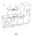
- Fig.1 shows in oblique view from the front a fitted kitchen 1 with several household appliances in the form of kitchen appliances, namely a stove 2 with an oven 3 and a hob 4, an extractor hood or dining 5, a dishwasher 6, a refrigerator 7 and a freezer 8.
- a washing machine 9 is also integrated.
- Each of the household appliances 3 to 9 has a docking station 10 to 13 indicated here by dashed lines.
- the portable control units 14 are similarly configured and each capable of docking at each of the household appliances 3 to 9 equipped with a docking station 10 to 13, 15, 16.
- the attachment may for example be mechanical (by insertion, placement, attachment, snapping, etc.) or magnetic and depend on the type of household appliance 3 to 9.
- the portable control unit 14 is inserted for docking to the hob 4 in a docking station in the form of an upper-side trough 15 of the hob 4 and held there magnetically.
- a short-range wireless communication channel between the hob 4 and the portable control unit 14 is opened.
- the two devices 4, 14 each have a wireless interface.
- power can be wirelessly transmitted from the hob 4 to the portable control unit 14, e.g.
- the hob 4 has for this purpose a magnetic field generating unit (o. Fig.)
- an energy absorbing means in the form of at least one induction coil (not shown) for tapping energy from the magnetic field.
- the magnetic field generating unit and the at least one induction coil may form part of the respective interface.
- the portable operating unit 14 With the opening of the communication channel, the portable operating unit 14 recognizes the hob 4 and configures itself so that it appears as an operating unit only of the hob 4. For this purpose, corresponding user interfaces for operating only the hob 4 are displayed.
- the portable control unit 14 is equipped with a detection means.
- the configuration means may comprise, for example, a data memory.
- a look-up table may be stored, which associates an identifier received via the communication channel with a predetermined household appliance.
- the identifier can at least partially also be transmitted in plain text.
- the respective portable control unit 14 is further equipped with a configuration means.
- the configuration means may comprise, for example, a data memory in which predetermined identifiable home appliances associated operating information such as menu structures, notes, key assignments, etc. may be stored.
- the operating sequences may also have recipes, etc. within the scope of an operating sequence of the oven 3 and / or the hob 4.
- the configuration means and the recognition means may be combined in a configuration and recognition means, which for example has a shared data memory.
- the data memory may be at least writable for its updating and be present, for example, as an EEPROM.
- the portable operating unit 14 may have an external computer interface for connection to a computer, for example a USB interface. This computer interface may correspond to the at least one interface for communication with the household appliance 3 to 9 or be an independent interface.
- a user has no way to operate or monitor another of the household appliances 3, 5 to 9 through this portable control unit 14 with an open communication channel between the portable control unit 14 and the hob 4.
- the short-range communication channel breaks down. This is detected by the hob 4, and the hob 4 reacts thereto at least with a shutdown of its associated cooking zones, possibly even with a complete switching off of the hob. 4
- the same or a similar portable control unit 14 can be docked as shown here on a front of the Esse 5 by being held there magnetically. By docking, the portable operating unit 14 recognizes the butt 5 and configures itself to appear as an operating unit of the butt 5 only. A user has none Possibility to operate or monitor another of the household appliances 3, 4, 6 to 9. With undocking or removal of the portable control unit 14 from the butt 5, the eating 5 turns off.
- the portable operating unit 14 is also equipped with a communication unit for in-house communication, e.g. with a bluetooth transceiver so that it can be connected to one or more household appliances 3 to 9 over a greater distance, eg. B. of up to about 10 m or 20 m, can communicate if it is not docked to one of these household appliances 3 to 9.
- the communication can also be done with household appliances 3 to 9, to which another portable control unit 14 is already docked.
- the communication between the home appliance 3 to 9 and the non-docked portable control unit 14 can then pass through the communication units for in-house communication of the docked portable control unit 14 and the non-docked portable control unit 14.
- the non-docked portable operating unit 14 can be used, for example, for status inquiry (remaining time of a cooking process, remaining time of a wash cycle, etc.).
- a portable control unit 14 may be included in a purchase of one of the household appliances 3 to 9, so that a user after buying several set up and equipped for cooperation with the portable control unit 14 home appliances 3 to 9 also has multiple portable control units 14. Unless all the home appliances 3 to 9 so set up are operated at the same time, portable control units 14 are left, which e.g. can be used for status monitoring. For docking to one of the household appliances 3 to 9, any of the enclosed portable control units 14 may be used.
- the portable control unit 14 has here as the display unit an LCD screen 17 and as controls mechanical short-stroke keys 18. At least the oven 3 and the hob 4 have to operate it yet another control in the form of an on / off switch 19.
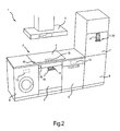
- Fig.2 shows the kitchen 1 from Fig.1 , wherein now other household appliances are equipped with a portable control unit 14, namely the oven 3 and the refrigerator. 7
- the docking station 11 of the refrigerator 7 is designed such that it has a protruding from the front attachment surface 20 to the attachment of the portable control unit 14.
- a plug (not shown) is inserted as the wired interface to which a mating socket can be placed as the wired interface of the portable operating unit 14, both for data communication between the refrigerator 7 and the portable operating unit 14 as well to the power supply of the portable control unit 14.
- the top surface 20 can, for. B. similar to a so-called. 'Cradle', a secure state of the portable control unit 14 can be achieved.
- the docking station 11 can also be provided with a depression formed above the top surface 20 in the front side of the refrigerator 7 (not shown) in order to support a secure fit of the portable control unit 14.
- the docking station 10 of the oven 3 is integrated in a front side of the oven 3 and has a folding mechanism (o. Fig.) For unfolding the portable control unit 14 from a substantially vertical position to a user down.
- the portable control unit 14 is shown here in the unfolded position, in which a user can operate the oven 3 comfortably standing up.
- the portable operating unit may only have one (wired or wireless) external interface with the household appliance.
- the portable control unit may also have only a touch screen instead of separate controls and display panel (s).
- the portable control unit can be flexible for adaptation to curved surfaces.
- the portable control unit can continue depending on the docked household appliance at a distance of the portable control unit or turn off. Turning off is particularly preferred in the case of a cooktop.
Landscapes
- Engineering & Computer Science (AREA)
- General Engineering & Computer Science (AREA)
- Combustion & Propulsion (AREA)
- Mechanical Engineering (AREA)
- Chemical & Material Sciences (AREA)
- Theoretical Computer Science (AREA)
- Physics & Mathematics (AREA)
- Thermal Sciences (AREA)
- Computer Hardware Design (AREA)
- Human Computer Interaction (AREA)
- General Physics & Mathematics (AREA)
- Computer Networks & Wireless Communication (AREA)
- Textile Engineering (AREA)
- Selective Calling Equipment (AREA)
- User Interface Of Digital Computer (AREA)
Description
- Die Erfindung betrifft ein Verfahren zum Betreiben eines Haushaltsgeräts.
- Zur Bedienung eines Haushaltsgeräts weist dieses häufig ein in eine Bedienblende integriertes Bedien- und Anzeigenfeld auf.
- Alternativ ist eine portable Bedieneinheit bekannt, welche an ein Haushaltsgerät andockbar ist und welche in der Lage ist, sämtliche dazu ausgestalteten Haushaltsgeräte in der Nähe gleichzeitig zu bedienen. Diese Bedieneinheit kann auch getrennt von einem Haushaltsgerät angeordnet werden und die Haushaltsgeräte entsprechend aus der Entfernung ("remote") bedienen.
- Es sind ferner stationäre zentrale Bedienanlagen zur Bedienung mehrerer Haushaltsgeräte bekannt.
- Es ist auch bekannt, Haushaltsgeräte von einem Computer, einem elektronischen Handheldgerät oder von einem Mobiltelefon aus zu bedienen.
-
DE 693 07 480 T2 offenbart einen Schalter zum Steuern des elektrischen Ein- oder Ausschaltens eines Elements, besonders Heizelements, durch eine keine Bohrung aufweisende bandförmige Tafel oder Platte aus Glas eines Haushalts-Kochgeräts hindurch, um das Kippen mindestens eines Relais , das einen dieses Element enthaltenden elektrischen Schaltkreis öffnet oder schließt, mittels eines Permanentmagneten zu bewirken, wobei dieses Relais ein in einem festen Chassis gegen die zum Inneren des Geräts gelegenen Seite der Glasplatte unbeweglich montiertes Magnetrelais ist und der Schalter einen Schaltknopf aufweist, der gegen die entgegengesetzte Seite der Platte anliegt, die nach außen gerichtet und für den Benutzer des Geräts zugänglich ist, dadurch gekennzeichnet, daß dieser Schaltknopf gegenüber der Platte um einen Zapfen frei drehbar ist, dessen Anordnung auf der Fläche derselben so festgelegt ist, daß der Schaltknopf in der Nähe des gegen die andere Seite montierten Relais angeordnet ist, und der Schaltknopf in einer durch den Zapfen gehenden Ebene radial versetzt den Permanentmagneten in der Weise aufweist, dass der Magnet bei Drehung des Schaltknopfes auf dem Zapfen in eine Stellung geradlinig gegenüber dem Relais gebracht wird und das automatische Kippen und Schließen desselben bewirkt, oder gegenüber diesem Relais verschoben wird, wodurch dieses automatisch in den Öffnungszustand zurückkehrt, wobei der Zapfen die Anordnung des Schaltknopfes festlegt, der um ihn drehbar ist, und mit einer offenen Aufnahme zusammenwirkt, die in der Mitte des Schaltknopfs in seiner gegen die Platte anliegenden Fläche hohl ausgebildet ist. -
EP 1 349 281 A2 offenbart eine Bedieneinheit mit einem Drehknebel, welche eine integrierte Lagervorrichtung aufweist. Mit dieser Lagervorrichtung ist die Bedieneinheit magnetisch an einer Abdeckung befestigbar. Die Bedieneinheit weist eine Steuerung mit einem Mikroprozessor auf zur Auswertung von magnetischen Signalmitteln, welche eine Drehung des Drehknebels gegenüber der Lagervorrichtung feststellen. Durch einen ersten Übertrager in der Bedieneinheit und einen zweiten Übertrager an der Unterseite der Abdeckung können eine Signalübertragung sowie eine Energieübertragung zwischen Bedieneinheit und Elektrogerät erfolgen. -
EP 0 802 465 A2 offenbart ein elektrisches Hausgerät, wie einen Geschirrspüler, einen Wäschetrockner, eine Waschmaschine, eine Beleuchtungseinrichtung, eine Heizungssteuerung oder dergleichen wobei über eine am oder im Hausgerät angeordnete Schnittstelle an ein zu mehreren Hausgeräten geführtes, von einem einzigen zentralen Steuerrechner steuerbares Bussystem anschließbar ist, wobei die Schnittstelle mit einem Busanschlussbaustein zur Übertragung von Steuerbefehlen und/oder Steuersignalen zwischen dem Bussystem und dem Hausgerät verbunden ist. Das Hausgerät ist mit einem Steckplatz zum lösbaren Anstecken des Steuerrechners versehen. Eine die Verbindung des angesteckten Steuerrechners mit der Schnittstelle herstellende Kontaktanordnung ist am Steckplatz angeordnet. Da der Steuerrechner auch an Steckplätzen anderer am Bussystem angeschlossener Hausgeräte angesteckt werden kann, wird eine große Flexibilität erreicht. Durch Umstecken des Steuerrechners kann die gesamte Anlage daher von verschiedenen Stellen aus gesteuert werden. Der Steuerrechner benötigt dabei keinen besonderen Platz, sondern ist im eingesteckten Zustand in einem der Hausgeräte integriert. Es ist die Aufgabe der vorliegenden Erfindung, eine einfach implementierbare Möglichkeit zur Bedienung von Haushaltsgeräten bereitzustellen, welche eine bequeme Reinigbarkeit der Haushaltsgeräte ermöglicht. - Diese Aufgabe wird gemäß den Merkmalen des unabhängigen Anspruchs gelöst. Bevorzugte Ausführungsformen sind den abhängigen Ansprüchen entnehmbar.
- Das Verfahren dient zum Betreiben eines Haushaltsgeräts und weist die Schritte gemäss Anspruch 1 auf.
- Im Gegensatz zu den Haushaltsgeräten mit dem integrierten Bedien- und Anzeigenfeld kann hier durch die grundsätzliche einfache und schnelle Abnehmbarkeit der Bedieneinheit eine bessere Reinigbarkeit des Haushaltsgeräts erreicht werden. Auch kann eine ruhigere, hochwertigere Gestaltung der zugehörigen Oberfläche erreicht werden. Ferner lassen sich die jeweiligen integrierten Bedien- und Anzeigenfelder einsparen, was besonders kostengünstige Haushaltsgeräte ermöglicht.
- Im Gegensatz zu Computern, Handheld-Geräten usw. ist durch die automatische Erkennung des Haushaltsgeräts nach dem Andocken zur Aktivierung der portablen Bedieneinheit keine für einen Benutzer eines Haushaltsgeräts vergleichsweise ungewohnte und komplexe Interaktion (kein Aufruf bestimmter Programme, keine Freischaltung von Kommunikationsleitungen usw.) notwendig. Auch ist die portable Bedieneinheit weit einfacher und fehlerunanfälliger ausgestaltbar.
- Im Gegensatz zu einer portablen Bedieneinheit, welche in der Lage ist, mehrere Haushaltsgeräte gleichzeitig zu bedienen, ist die portable Bedieneinheit durch die Konzentration auf die Bedienung nur eines Haushaltsgerät weit einfacher ausgestaltbar und somit preiswerter herzustellen. So braucht in der portablen Bedieneinheit keine Möglichkeit für eine Mehrgeräte-Kommunikation vorgesehen zu werden. Bei der Bedienung nur eines Haushaltsgeräts kann insbesondere auf eine Vernetzung der Haushaltsgeräte verzichtet werden. Auch wird die Bedienung übersichtlicher.
- Das erfindungsgemässe Verfahren weist folgenden Schritt auf: Abdocken oder Entfernen der portablen Bedieneinheit von dem Haushaltsgerät und dadurch Ausschalten des Haushaltsgeräts. So kann verhindert werden, dass auf eine unerwünschte Handlung oder eine Fehlfunktion des Haushaltsgeräts nicht rechtzeitig reagiert werden kann.
- Die portable Bedieneinheit ist aufgrund ihrer potenziellen Verwendung mit mehreren Haushaltsgeräten in hohen Stückzahlen und damit besonders preiswert herstellbar.
- Die portable Bedieneinheit weist einem Bildschirm auf. Bedienelemente können Schalter, Taster, Slider usw. umfassen, Anzeigenelemente können LED-Bildschirme, LCD-Bildschirme, TFT-Bildschirme, Segmentanzeigen usw. umfassen, und zwar auch berührungsempfindliche Bildschirme (Touchscreens).
- Ein Konfigurieren umfasst eine Anzeige entsprechender Bedienoberflächen.
- Bei der Konfiguration wird somit die portable Bedieneinheit so konfiguriert, dass sie nur das Haushaltsgerät bedienen kann, an dem sie gerade angedockt ist. Durch das Andockmittel kann insbesondere sowohl eine Befestigung der portablen Bedieneinheit an dem Haushaltsgerät als auch eine funktionale Kopplung mit dem Haushaltsgerät hergestellt werden.
- Es kann eine Weiterbildung sein, dass das Andockmittel eine drahtgebundene externe Schnittstelle umfasst. Dadurch ist eine besonders einfach zu implementierende und störsichere Verbindung zwischen der portablen Bedieneinheit und dem Haushaltsgerät herstellbar. Diese drahtgebundene externe Schnittstelle kann eine proprietäre Schnittstelle oder eine standardisierte Schnittstelle, wie eine USB-Schnittstelle, sein.
- Es kann auch eine Weiterbildung sein, dass das Andockmittel eine kurzreichweitige drahtlose externe Schnittstelle umfasst. Durch die kurze Reichweite, z. B. von bis zu 2 cm bis 10 cm, kann ein Übersprechen mit anderen Kommunikationskanälen vermieden werden. Die drahtlose externe Schnittstelle kommt ohne ein körperliches Verbindungselement (Stecker usw.) aus und ist folglich besonders einfach zu reinigen und optisch unauffällig.
- Gemäß noch einer Weiterbildung kann die portable Bedieneinheit ein Energieaufnahmemittel aufweisen. Die portable Bedieneinheit kann über das Energieaufnahmemittel mit Energie versorgt werden, z.B. zur Sicherstellung eines laufenden Betriebs und / oder zur Aufladung eines Akkumulators. Das Energieaufnahmemittel kann in das Andockmittel integriert oder damit funktional verbunden sein. Bei einer Integration oder einer funktionalen Verbindung mit der drahtgebundenen externen Schnittstelle kann dazu als das Energieaufnahmemittel ein Stromversorgungsanschluss vorgesehen sein. Bei einer Integration oder einer funktionalen Verbindung mit der drahtlosen externen Schnittstelle kann beispielsweise Energie durch ein entsprechendes elektromagnetisches Feld von dem Haushaltsgerät auf die portable Bedieneinheit übertragen werden, wobei die portable Bedieneinheit als das Energieaufnahmemittel mindestens eine Induktionsspule aufweisen kann.
- Es kann noch eine Ausgestaltung sein, dass die portable Bedieneinheit eine externe Rechner-Schnittstelle zum Anschluss an einen Rechner aufweist, z.B. einen USB-Anschluss. Diese externe Rechner-Schnittstelle kann zumindest einer Schnittstelle zu dem Haushaltsgerät entsprechen oder eine separate Schnittstelle sein. Über die Rechner-Schnittstelle kann die portable Bedieneinheit aktualisiert werden, beispielsweise durch ein Hinzufügen weiterer Geräte, mit denen die portable Bedieneinheit zusammenarbeiten kann, oder durch eine Aktualisierung der Konfiguration der portablen Bedieneinheit (z.B. durch neue Rezepte zur Durchführung von Garprogrammen eines Backofens). Es ist eine Ausgestaltung, dass die portable Bedieneinheit über den Rechner mit einem Netzwerk wie z. B. dem Internet verbunden sein kann.
- Es kann eine weitere Ausgestaltung sein, dass die portable Bedieneinheit eine einheitlich gestaltete Bedienerführung für die bedienbaren Haushaltsgeräte aufweist. Eine einheitliche Bedienerführung kann optisch nach dem gleichen Muster oder Design aufgebaute Anzeigeninhalte und / oder nach dem gleichen Konzept aufgebaute Menüstrukturen umfassen. Dadurch kann eine vertraute Bedienerführung für einige oder alle durch die portable Bedieneinheit bedienbaren Haushaltsgeräte erreicht werden, was einen Bedienkomfort erhöht.
- Es kann ferner eine Ausgestaltung sein, dass die portable Bedieneinheit eine Kommunikationseinheit zur In-Haus-Kommunikation mit zu erkennenden Haushaltsgeräten aufweist, falls die portable Bedieneinheit nicht an eines der zu erkennenden Haushaltsgeräte angedockt ist. Dadurch kann eine portable Bedieneinheit beispielsweise zur Statusüberwachung von Haushaltsgeräten eingesetzt werden, wenn sie nicht zur Bedienung eines bestimmten Haushaltsgeräts eingesetzt wird.
- Die Andockstation kann beispielsweise eine mechanische Halterung und / oder eine magnetische Halterung zur Befestigung der portablen Bedieneinheit bereitstellen. Eine mechanische Halterung kann eine Einsteck- oder Einschubeinheit (z.B. eine sog. Cradle), einen Auflageeinheit (z.B. eine Mulde), eine Einhängeeinheit und / oder eine Einrasteinheit usw. umfassen.
- Es ist eine Ausgestaltung, dass die Andockstation in eine Frontseite des Haushaltsgeräts integriert ist und eine aus der Frontseite hervorstehende Aufsatzfläche zum Aufsatz der portablen Bedieneinheit aufweist. Dadurch kann ein sicherer Stand der portablen Bedieneinheit erreicht werden.
- Es ist noch eine Ausgestaltung, dass die Andockstation in eine Frontseite des Haushaltsgeräts integriert ist und einen Klappmechanismus zum Ausklappen der portablen Bedieneinheit aus einer im Wesentlichen senkrechten Stellung aufweist. Dadurch kann insbesondere bei tiefer angeordneten Haushaltsgeräten, insbesondere Unterbaugeräten, eine Bedienung vereinfacht werden, da die portable Bedieneinheit zu einem Benutzer hin verschwenkbar ist, was eine Handhabung erleichtert.
- Alternativ kann der Klappmechanismus auch in die portable Bedieneinheit integriert sein (z. B. an einer Rückseite), um so die Frontseite des Haushaltsgeräts preiswert, einfach reinigbar und hochwertig anmutend zu halten.
- Der Klappmechanismus kann so ausgestaltet sein, dass er als ein Stützmechanismus zur Aufstellung der portablen Bedieneinheit auf einer freien Fläche nutzbar ist. Dies weist den Vorteil auf, dass die portable Bedieneinheit (z.B. zur Statusüberwachung) auch unabhängig von einer Andockstation sicher und ergonomisch vorteilhaft positionierbar ist.
- Eine weitere Ausprägung kann es sein, dass die Andockstation in eine Frontseite des Haushaltsgeräts integriert ist und eine nach oben schräg gerichtete Oberfläche bzw. einen nach oben schräg gestellten Bereich aufweist, an welcher die portable Bedieneinheit lösbar befestigbar ist. Dadurch kann ein Benutzer auch ohne einen Klappmechanismus einen komfortablen Einblickwinkel auf die portable Bedieneinheit erlangen. Der schräggestellte Bereich lässt sich ebenfalls gut reinigen und kann gestalterisch dezent ausgeführt sein. Ein Vorsehen des schräggestellten Bereichs kann insbesondere bei Unterbaugeräten, speziell bei einem Backofen, vorteilhaft sein.
- Es ist eine weitere Ausgestaltung, dass das Haushaltsgerät außer der portablen Bedieneinheit mindestens ein weiteres, fest installiertes Bedien- und / oder Anzeigenelement aufweist. Dadurch kann eine zumindest rudimentäre Bedienung des Haushaltsgeräts auch bei einem Fehlen der portablen Bedieneinheit (z.B. bei einem Verlust oder bei einem niedrigen Ladepegel der portablen Bedieneinheit) aufrechterhalten werden. Aus Sicherheitsgründen wird es besonders bevorzugt, wenn das mindestens eine fest installierte Bedien- und / oder Anzeigenelement einen Hauptschalter umfasst.
- In den folgenden Figuren wird die Erfindung anhand eines Ausführungsbeispiels schematisch beschrieben. Dabei können zur Übersichtlichkeit gleiche oder gleichwirkende Elemente mit gleichen Bezugszeichen versehen sein.
- Fig.1
- zeigt in Ansicht von schräg vorne eine Einbauküche mit mehreren Haushaltsgeräten, von denen zwei mit einer portablen Bedieneinheit ausgerüstet sind;
- Fig.2
- zeigt die Einbauküche aus
Fig.1 , wobei nun zwei andere Haushaltsgeräte mit einer portablen Bedieneinheit ausgerüstet sind. -
Fig.1 zeigt in Ansicht von schräg vorne eine Einbauküche 1 mit mehreren Haushaltsgeräten in Form von Küchengeräten, nämlich einen Herd 2 mit einem Backofen 3 und einem Kochfeld 4, eine Dunstabzugshaube oder Esse 5, eine Geschirrspülmaschine 6, einen Kühlschrank 7 und eine Gefriertruhe 8. In die Einbauküche 1 ist ferner eine Waschmaschine 9 integriert. Jedes der Haushaltsgeräte 3 bis 9 weist eine hier gestrichelt angedeutete Andockstation 10 bis 13 auf. An den Andockstationen 15, 16 des Kochfelds 4 bzw. der Esse 5 sind portable Bedieneinheiten 14 angedockt. Die portablen Bedieneinheiten 14 sind gleichartig ausgestaltet und jeweils in der Lage, an jedem der mit einer Andockstation 10 bis 13, 15, 16 ausgerüsteten Haushaltsgeräte 3 bis 9 anzudocken. - Zur Bedienung eines der Haushaltsgeräte 3 bis 9 ist vorgesehen, eine portable Bedieneinheit 14 an die zugehörige Andockstation 10 bis 13, 15, 16 anzudocken und dadurch daran zu befestigen. Die Befestigung kann beispielsweise mechanisch (durch Einschieben, Auflegen, Anhängen, Einrasten usw.) oder magnetisch erfolgen und von der Art des Haushaltsgeräts 3 bis 9 abhängen.
- So wird die portable Bedieneinheit 14 zum Andocken an das Kochfeld 4 in eine Andockstation in Form einer oberseitigen Mulde 15 des Kochfelds 4 eingelegt und dort magnetisch gehalten. Durch das Andocken wird ein kurzreichweitiger drahtloser Kommunikationskanal zwischen dem Kochfeld 4 und der portablen Bedieneinheit 14 geöffnet. Dazu weisen die beiden Geräte 4, 14 jeweils eine drahtlose Schnittstelle auf. Ferner kann drahtlos Energie von dem Kochfeld 4 auf die portable Bedieneinheit 14 übertragen werden, z.B. zum Aufladen eines Akkumulators der portablen Bedieneinheit 14. Das Kochfeld 4 weist zu diesem Zweck eine Magnetfeld-Erzeugungseinheit (o. Abb.) zur Erzeugung eines Magnetfelds am Ort der portablen Bedieneinheit 14 auf, während die portable Bedieneinheit 14 ein Energieaufnahmemittel in Form mindestens einer Induktionsspule (o. Abb.) zum Abgriff von Energie aus dem Magnetfeld aufweist. Die Magnetfeld-Erzeugungseinheit und die mindestens eine Induktionsspule können einen Teil der jeweiligen Schnittstelle darstellen.
- Mit dem Öffnen des Kommunikationskanals erkennt die portable Bedieneinheit 14 das Kochfeld 4 und konfiguriert sich so, dass es als eine Bedieneinheit nur des Kochfelds 4 erscheint. Dazu werden entsprechende Bedienoberflächen zur Bedienung nur des Kochfelds 4 angezeigt.
- Zur Erkennung des mit ihr kommunikativ verbundenen Haushaltsgeräts 4, 5 ist die portable Bedieneinheit 14 mit einem Erkennungsmittel ausgerüstet. Das Konfigurationsmittel kann beispielsweise einen Datenspeicher umfassen. In dem Datenspeicher kann beispielsweise eine Nachschlagetabelle gespeichert sein, welche eine über den Kommunikationskanal empfangene Kennung mit einem vorbestimmten Haushaltsgerät verknüpft. Die Kennung kann zumindest teilweise auch in Klartext übermittelt werden.
- Zu ihrer Konfiguration auf das mit ihr kommunikativ verbundene Haushaltsgerät 4, 5 ist die jeweilige portable Bedieneinheit 14 ferner mit einem Konfigurationsmittel ausgerüstet. Das Konfigurationsmittel kann beispielsweise einen Datenspeicher umfassen, in dem zu vorbestimmten erkennbaren Haushaltsgeräten zugehörige Bedieninformationen wie Menüstrukturen, Hinweistexte, Tastenbelegungen usw. gespeichert sein können. Die Bedienabläufe können im Rahmen eines Bedienablaufs des Backofens 3 und / oder des Kochfelds 4 auch Rezepte usw. aufweisen.
- Das Konfigurationsmittel und das Erkennungsmittel können in einem Konfigurations- und Erkennungsmittel kombiniert sein, welches beispielsweise einen gemeinsamen Datenspeicher aufweist.
- Der Datenspeicher kann zu seiner Aktualisierung mindestens beschreibbar sein und beispielsweise als ein EEPROM vorliegen. Für eine Aktualisierung kann die portable Bedieneinheit 14 eine externe Rechner-Schnittstelle zum Anschluss an einen Rechner aufweisen, beispielsweise eine USB-Schnittstelle. Diese Rechner-Schnittstelle kann der mindestens einen Schnittstelle zur Kommunikation mit dem Haushaltsgerät 3 bis 9 entsprechen oder eine eigenständige Schnittstelle sein.
- Ein Benutzer hat bei offenem Kommunikationskanal zwischen der portablen Bedieneinheit 14 und dem Kochfeld 4 keine Möglichkeit zur Bedienung oder Überwachung eines anderen der Haushaltsgeräte 3, 5 bis 9 durch diese portable Bedieneinheit 14.
- Mit Abdocken bzw. Entfernen der portablen Bedieneinheit 14 von dem Kochfeld 4 bzw. aus der Mulde 15 bricht der kurzreichweitige Kommunikationskanal zusammen. Dies wird durch das Kochfeld 4 erkannt, und das Kochfeld 4 reagiert darauf zumindest mit einem Abschalten seiner zugehörigen Kochstellen, ggf. auch mit einem vollständigen Ausschalten des Kochfelds 4.
- Die gleiche oder eine gleichartige portable Bedieneinheit 14 kann wie hier gezeigt auch an eine Vorderseite der Esse 5 angedockt werden, indem sie dort magnetisch gehalten wird. Durch das Andocken erkennt die portable Bedieneinheit 14 die Esse 5 und konfiguriert sich so, dass sie als eine Bedieneinheit nur der Esse 5 erscheint. Ein Benutzer hat keine Möglichkeit zur Bedienung oder Überwachung eines anderen der Haushaltsgeräte 3, 4, 6 bis 9. Mit Abdocken bzw. Entfernen der portablen Bedieneinheit 14 von der Esse 5 schaltet sich die Esse 5 aus.
- Die portable Bedieneinheit 14 ist auch mit einer Kommunikationseinheit zur In-House-Kommunikation ausgerüstet, z.B. mit einem Bluetooth-Transceiver, so dass sie mit einem oder mehreren Haushaltsgeräten 3 bis 9 über eine größere Entfernung, z. B. von bis zu ca. 10 m oder 20 m, kommunizieren kann, falls sie nicht an eines dieser Haushaltsgeräte 3 bis 9 angedockt ist. Die Kommunikation kann auch mit Haushaltsgeräten 3 bis 9 erfolgen, an welche bereits eine andere portable Bedieneinheit 14 angedockt ist. Die Kommunikation zwischen dem Haushaltsgerät 3 bis 9 und der nicht-angedockten portablen Bedieneinheit 14 kann dann über die Kommunikationseinheiten zur In-House-Kommunikation der angedockten portablen Bedieneinheit 14 und der nicht-angedockten portablen Bedieneinheit 14 laufen. Die nicht-angedockte portable Bedieneinheit 14 kann beispielsweise zur Statusabfrage (Restdauer eines Garvorgangs, Restdauer eines Waschgangs usw.) verwendet werden.
- Eine portable Bedieneinheit 14 kann bei einem Kauf eines der Haushaltsgeräte 3 bis 9 beiliegen, so dass ein Benutzer nach einem Kauf mehrerer zur Zusammenarbeit mit der portablen Bedieneinheit 14 eingerichteten und ausgerüsteten Haushaltsgeräte 3 bis 9 auch mehrere portable Bedieneinheiten 14 besitzt. Falls nicht alle so eingerichteten Haushaltsgeräte 3 bis 9 gleichzeitig betrieben werden, sind portable Bedieneinheiten 14 übrig, welche z.B. zur Statusüberwachung verwendet werden können. Zum Andocken an eines der Haushaltsgeräte 3 bis 9 kann jede der beiliegenden portablen Bedieneinheiten 14 verwendet werden.
- Die portable Bedieneinheit 14 weist hier als die Anzeigeneinheit einen LCD-Bildschirm 17 sowie als Bedienelemente mechanische Kurzhubtasten 18 auf. Zumindest der Backofen 3 und das Kochfeld 4 weisen zu ihrer Bedienung noch ein weiteres Bedienelement in Form eines Ein/Aus-Schalters 19 auf.
-
Fig.2 zeigt die Einbauküche 1 ausFig.1 , wobei nun andere Haushaltsgeräte mit einer portablen Bedieneinheit 14 ausgerüstet sind, nämlich der Backofen 3 und der Kühlschrank 7. - Die Andockstation 11 des Kühlschranks 7 ist so ausgestaltet, dass sie eine aus der Frontseite hervorstehende Aufsatzfläche 20 zum Aufsatz der portablen Bedieneinheit 14 aufweist. In die Aufsatzfläche 20 ist ein Stecker (o. Abb.) als die drahtgebundene Schnittstelle eingelassen, auf den eine passende Buchse als die drahtgebundene Schnittstelle der portablen Bedieneinheit14 aufsetzbar ist, und zwar sowohl zur Datenkommunikation zwischen dem Kühlschrank 7 und der portablen Bedieneinheit 14 als auch zur Stromversorgung der portablen Bedieneinheit 14. Durch die Aufsatzfläche 20 kann, z. B. ähnlich einer sog. 'Cradle', ein sicherer Stand der portablen Bedieneinheit 14 erreicht werden. Die Andockstation 11 kann zudem mit einer oberhalb der Aufsatzfläche 20 in der Frontseite des Kühlschranks 7 ausgebildeten Vertiefung (o. Abb.) versehen sein, um einen sicheren Sitz der portablen Bedieneinheit 14 zu unterstützen.
- Die Andockstation 10 des Backofens 3 ist in eine Frontseite des Backofens 3 integriert und weist einen Klappmechanismus (o. Abb.) zum Ausklappen der portablen Bedieneinheit 14 aus einer im Wesentlichen senkrechten Stellung zu einem Benutzer hin auf. Die portable Bedieneinheit 14 ist hier in der ausgeklappten Stellung gezeigt, in der ein Benutzer den Backofen 3 bequem im Stehen bedienen kann.
- Selbstverständlich ist die vorliegende Erfindung nicht auf das gezeigte Ausführungsbeispiel beschränkt.
- So mag die portable Bedieneinheit in einer anderen Ausgestaltung nur eine (drahtgebundene oder drahtlose) externe Schnittstelle mit dem Haushaltsgerät aufweisen.
- Die portable Bedieneinheit kann auch lediglich einen Touchscreen anstelle getrennter Bedienelemente und Anzeigenfeld(er) aufweisen.
- Die portable Bedieneinheit kann zur Anpassung an gekrümmte Oberflächen biegsam sein.
- Die portable Bedieneinheit kann abhängig von dem angedockten Haushaltsgerät bei einer Entfernung der portablen Bedieneinheit weiterlaufen oder sich ausschalten. Ein Ausschalten wird insbesondere im Falle eines Kochfelds bevorzugt.
-
- 1 Einbauküche
- 2 Herd
- 3 Backofen
- 4 Kochfeld
- 5 Esse
- 6 Geschirrspülmaschine
- 7 Kühlschrank
- 8 Gefriertruhe
- 9 Waschmaschine
- 10 Andockstation
- 11 Andockstation
- 12 Andockstation
- 13 Andockstation
- 14 portable Bedieneinheit
- 15 Andockstation / Mulde des Kochfelds
- 16 Andockstation
- 17 LCD-Bildschirm
- 18 Kurzhubtaste
- 19 Ein/Aus-Schalter
- 20 Aufsatzfläche
Claims (12)
- Verfahren zum Betreiben eines Haushaltsgeräts (2-9), wobei das Verfahren die folgenden Schritte aufweist:- Andocken einer portablen Bedieneinheit (14) an das Haushaltsgerät (2-9), wobei die portable Bedieneinheit (14) einen Bildschirm (17) aufweist;- Erkennen des Haushaltsgeräts (2-9) durch die portable Bedieneinheit (14);- Konfigurieren der portablen Bedieneinheit (14) nur zur Bedienung dieses Haushaltsgeräts (2-9), wobei auf dem Bildschirm (17) der Bedieneinheit (14) eine entsprechende Bedienoberfläche zur Bedienung nur dieses Haushaltsgeräts (2-9) angezeigt wird;- Abdocken der portablen Bedieneinheit (14) von dem Haushaltsgerät (2-9) und dadurch- Ausschalten des Haushaltsgeräts (2-9).
- Verfahren nach Anspruch 1, wobei die portable Bedieneinheit (14) ferner mindestens aufweist:- mindestens ein Andockmittel zum Andocken an das Haushaltsgerät (2-9);- ein Erkennungsmittel zum Erkennen des Haushaltsgeräts (2-9) und- ein Konfigurationsmittel zu ihrer Konfiguration zur Bedienung dieses Haushaltsgeräts (2-9) und wobei- die portable Bedieneinheit (14) eine Rechner-Schnittstelle zum Anschluss an einen Rechner aufweist.
- Verfahren nach Anspruch 2, wobei das Andockmittel eine drahtgebundene externe Schnittstelle umfasst.
- Verfahren nach einem der Ansprüche 2 bis 3, wobei das Andockmittel eine kurzreichweitige drahtlose externe Schnittstelle umfasst.
- Verfahren nach einem der vorhergehenden Ansprüche, wobei der Bildschirm (17) ein berührungsempfindlicher Bildschirm ist.
- Verfahren nach einem der Ansprüche 2 bis 5, wobei portable Bedieneinheit (14) eine einheitliche Bedienerführung für mehrere bedienbare Haushaltsgeräte (2-9) aufweist.
- Verfahren nach einem der Ansprüche 2 bis 6, wobei sie eine Kommunikationseinheit zur In-Haus-Kommunikation mit zu erkennenden Haushaltsgeräten (2-9) aufweist, falls die portable Bedieneinheit (14) nicht an eines der zu erkennenden Haushaltsgeräte (2-9) angedockt ist.
- Verfahren nach einem der vorhergehenden Ansprüche, wobei das Haushaltsgerät (2-9) eine Andockstation (10-13, 15, 16) zum Andocken einer portablen Bedieneinheit (14) aufweist und wobei die Andockstation (10-13, 15, 16) in eine Frontseite des Haushaltsgeräts (2-9) integriert wird.
- Verfahren nach Anspruch 8, wobei die Andockstation (10-13, 15, 16) eine aus der Frontseite hervorstehende Aufsatzfläche (20) zum Aufsatz der portablen Bedieneinheit (14) aufweist.
- Verfahren nach Anspruch 8, wobei die Andockstation (10-13, 15, 16) einen Klappmechanismus zum Ausklappen der portablen Bedieneinheit (14) aus einer im Wesentlichen senkrechten Stellung aufweist.
- Verfahren nach Anspruch 8, wobei die Andockstation eine nach oben schräg gerichtete Oberfläche zur Befestigung der portablen Bedieneinheit aufweist.
- Verfahren nach einem der vorhergehenden Ansprüche 8 bis 11, dadurch gekennzeichnet, dass das Haushaltsgerät (2-9) mindestens ein fest installiertes Bedien- und / oder Anzeigenelement aufweist.
Applications Claiming Priority (2)
| Application Number | Priority Date | Filing Date | Title |
|---|---|---|---|
| DE102009002774A DE102009002774A1 (de) | 2009-04-30 | 2009-04-30 | Verfahren zum Betreiben eines Haushaltsgeräts, portable Bedieneinheit und Haushaltsgerät |
| PCT/EP2010/055180 WO2010124966A1 (de) | 2009-04-30 | 2010-04-20 | Verfahren zum betreiben eines haushaltsgeräts, portable bedieneinheit und haushaltsgerät |
Publications (2)
| Publication Number | Publication Date |
|---|---|
| EP2425182A1 EP2425182A1 (de) | 2012-03-07 |
| EP2425182B1 true EP2425182B1 (de) | 2015-06-10 |
Family
ID=42309716
Family Applications (1)
| Application Number | Title | Priority Date | Filing Date |
|---|---|---|---|
| EP10719294.0A Active EP2425182B1 (de) | 2009-04-30 | 2010-04-20 | Verfahren zum betreiben eines haushaltsgeräts |
Country Status (4)
| Country | Link |
|---|---|
| US (1) | US9007184B2 (de) |
| EP (1) | EP2425182B1 (de) |
| DE (1) | DE102009002774A1 (de) |
| WO (1) | WO2010124966A1 (de) |
Cited By (1)
| Publication number | Priority date | Publication date | Assignee | Title |
|---|---|---|---|---|
| DE102017209885A1 (de) * | 2017-06-12 | 2018-12-13 | BSH Hausgeräte GmbH | Drahtlose Kopplung eines Hausgeräts |
Families Citing this family (33)
| Publication number | Priority date | Publication date | Assignee | Title |
|---|---|---|---|---|
| DE102010028493A1 (de) * | 2010-05-03 | 2011-11-03 | BSH Bosch und Siemens Hausgeräte GmbH | Bedienteil für eine Haushaltsarbeitsstation, Haushaltsarbeitsstation sowie System aus der Haushaltsarbeitsstation und dem Bedienteil |
| DE102011004307B4 (de) | 2011-02-17 | 2018-05-09 | Siemens Aktiengesellschaft | Verfahren und Vorrichtung zur Autokonfiguration eines Gerätemoduls |
| DE102011087445A1 (de) * | 2011-11-30 | 2013-06-06 | BSH Bosch und Siemens Hausgeräte GmbH | Kontaktierung zwischen einer beweglichen Bedienblende und einem Korpus eines Haushaltsgeräts |
| DE102012210855A1 (de) * | 2012-06-26 | 2014-01-02 | BSH Bosch und Siemens Hausgeräte GmbH | Bedienteil für ein Haushaltsgerät |
| DE102012017380A1 (de) * | 2012-09-01 | 2014-03-06 | Exklusiv-Hauben Gutmann Gmbh | Dunstabzugshaube |
| DE102012217003A1 (de) * | 2012-09-21 | 2014-03-27 | BSH Bosch und Siemens Hausgeräte GmbH | Verfahren zum Betreiben eines Systems mit einer Mehrzahl von Haushaltsgeräten sowie System mit derartigen Haushaltsgeräten |
| DE102013104976A1 (de) * | 2013-05-15 | 2014-12-18 | Miele & Cie. Kg | System mit einem Haushaltsgerät und einer Kommunikationseinrichtung sowie Verfahren zum Betrieb eines solchen Systems |
| EP2805653B1 (de) | 2013-05-24 | 2020-07-08 | Taurus Research and Development, SLU | Kochgerät für die Bearbeitung und Zubereitung von Speisen |
| DE102013213811A1 (de) * | 2013-07-15 | 2015-01-15 | BSH Bosch und Siemens Hausgeräte GmbH | Bedienteilvorrichtung für Dunstabzugshaube und Dunstabzugshaube |
| US20150096974A1 (en) * | 2013-10-08 | 2015-04-09 | Bsh Home Appliances Corporation | Modular domestic cooking appliance with customizable cooking bays/ modules |
| DE102013223934A1 (de) | 2013-11-22 | 2015-05-28 | BSH Hausgeräte GmbH | Haushaltsgerät |
| DE102014201926B4 (de) * | 2014-02-04 | 2020-07-09 | BSH Hausgeräte GmbH | Haushaltsgerät |
| EP3111143A1 (de) | 2014-02-24 | 2017-01-04 | BSH Hausgeräte GmbH | Haushaltsgerät mit stelleinrichtung |
| KR20160010093A (ko) * | 2014-07-18 | 2016-01-27 | 삼성전자주식회사 | 가전 기기, 컨트롤러, 컨트롤러를 이용한 가전 기기 제어 시스템, 가전 기기의 제어 방법 및 상기 가전 기기의 제어 방법을 기록한 컴퓨터로 판독 가능한 기록 매체 |
| DE102014215778A1 (de) * | 2014-08-08 | 2016-02-11 | BSH Hausgeräte GmbH | Verfahren zum Betreiben eines Haushaltsgeräts mit einer haushaltsgeräteexternen Bedieneinheit sowie Haushaltsgerät |
| DE102014226025A1 (de) * | 2014-12-16 | 2016-06-16 | Robert Bosch Gmbh | Optische Anzeigevorrichtungseinheit zur Verwendung in einer externen Anwendungseinheit |
| KR101727046B1 (ko) * | 2015-07-07 | 2017-04-14 | 엘지전자 주식회사 | 조리기기와 주방기기의 연계 시스템 |
| DE102015222732A1 (de) * | 2015-11-18 | 2017-05-18 | BSH Hausgeräte GmbH | Haushaltsgerät mit einer Gerätekomponente mit von oben greifbarer Griffmulde |
| EP3264386A1 (de) * | 2016-06-28 | 2018-01-03 | Electrolux Appliances Aktiebolag | Externe benutzerschnittstelle zur steuerung von mindestens einem haushaltsgerät |
| JP2018179377A (ja) * | 2017-04-11 | 2018-11-15 | 株式会社ハーマン | 換気装置 |
| USD825734S1 (en) * | 2017-06-20 | 2018-08-14 | BSH Hausgeräte GmbH | Ventilation hood |
| EP3428541B1 (de) * | 2017-07-11 | 2020-05-06 | Electrolux Appliances Aktiebolag | Fernsteuerungssystem zur steuerung eines haushaltsgeräts |
| DE102018100840A1 (de) * | 2018-01-16 | 2019-07-18 | Miele & Cie. Kg | Verfahren zur verbesserten Einbindung eines WLAN-fähigen Haushaltsgeräts in eine Benutzerumgebung |
| DE102018204916A1 (de) * | 2018-03-29 | 2019-10-02 | Koenig & Bauer Ag | Verarbeitungsmaschinensystem und Verfahren zum Betreiben eines Verarbeitungsmaschinensystems |
| DE102019200772A1 (de) * | 2019-01-23 | 2020-07-23 | BSH Hausgeräte GmbH | Gargerät mit spezifischem Identifikationsmerkmal an einem Frontflansch |
| DE102019116756A1 (de) * | 2019-06-20 | 2020-12-24 | Wagener Gastronomieproduktion Gmbh | Ablufthaube und Ablufthaubensystem |
| DE102019219802A1 (de) * | 2019-12-17 | 2021-06-17 | BSH Hausgeräte GmbH | Hausgerät mit austauschbarem Bedien- und/oder Steuerteil |
| FI129281B (fi) * | 2020-02-20 | 2021-11-15 | Safera Oy | Liesituuletin tai -kupu, modulaarinen liesivahtijärjestely, sekä menetelmä ja järjestely liesivahdin valinnaiseksi liittämiseksi liesituulettimeen tai -kupuun |
| DE102020202990A1 (de) | 2020-03-10 | 2021-09-16 | BSH Hausgeräte GmbH | Bedienteil für unterschiedliche Typen von Hausgeräten |
| CN111580408A (zh) * | 2020-06-29 | 2020-08-25 | 广东美的厨房电器制造有限公司 | 家电系统和控制方法 |
| DE102021201801B3 (de) * | 2021-02-25 | 2022-07-21 | BORA - Vertriebs GmbH & Co KG | Tragbares Bediengerät zum Steuern eines Küchengeräts aus unterschiedlichen Bedienpositionen und Küchengerätesystem |
| EP4298383A1 (de) * | 2021-02-25 | 2024-01-03 | BORA - Vertriebs GmbH & Co KG | Tragbares bediengerät zum steuern eines küchengeräts aus unterschiedlichen bedienpositionen und küchengerätesystem |
| DE102021116541A1 (de) | 2021-06-25 | 2022-12-29 | Foshan Shunde Midea Washing Appliances MFG CO.,LTD | Vorrichtung zum Steuern eines Haushaltsgeräts |
Citations (8)
| Publication number | Priority date | Publication date | Assignee | Title |
|---|---|---|---|---|
| DE4229731A1 (de) | 1991-10-11 | 1993-04-15 | Seppelfricke Geb Gmbh | Vorrichtung zum schalten und steuern von haushaltsgeraeten |
| DE69307480T2 (de) * | 1992-12-04 | 1997-05-22 | Merloni Electromenager | Befehlsschalter für ein Haushaltskochgerät |
| DE29622066U1 (de) | 1996-12-19 | 1998-04-16 | Aeg Hausgeraete Gmbh | Hausgerät mit einem Bedienpult |
| WO1998017952A1 (en) | 1996-10-23 | 1998-04-30 | John Patrick Sale Nolan | Controlled heat transfer device |
| DE19802558A1 (de) | 1998-01-23 | 1999-07-29 | Ego Elektro Geraetebau Gmbh | Steuerung für ein Elektrowärmegerät |
| DE19849075A1 (de) | 1998-10-24 | 2000-04-27 | Ego Elektro Geraetebau Gmbh | Steuerung für ein Elektrogerät |
| DE10202493A1 (de) | 2002-01-23 | 2003-07-31 | Bsh Bosch Siemens Hausgeraete | Bedieneinrichtung für ein Haushaltsgerät |
| EP1906094A1 (de) | 2006-09-27 | 2008-04-02 | Electrolux Home Products N.V. | Gargerät |
Family Cites Families (6)
| Publication number | Priority date | Publication date | Assignee | Title |
|---|---|---|---|---|
| DE19615840A1 (de) | 1996-04-20 | 1997-10-30 | Bosch Gmbh Robert | Elektrisches Hausgerät |
| US7136914B2 (en) * | 2001-08-06 | 2006-11-14 | Ricoh Company, Ltd. | System, computer program product and method for managing and controlling a local network of electronic devices |
| DE10212954A1 (de) | 2002-03-19 | 2003-10-02 | Ego Elektro Geraetebau Gmbh | Bedienvorrichtung für ein Elektrogerät |
| DE10340627A1 (de) * | 2003-09-03 | 2005-04-07 | Infineon Technologies Ag | Steuerbare Hausgeräte-Anordnung und/oder steuerbare Industriegeräte-Anordnung und Steuersystem zum Steuern einer Hausgeräte-Anordnung und/oder Industriegeräte-Anordnung |
| IL160429A0 (en) * | 2004-02-16 | 2005-11-20 | Home Comfort Technologies Ltd | Environmental control system |
| ITMI20072129A1 (it) * | 2007-11-07 | 2009-05-08 | Whirlpool Co | Interfaccia utente per il comando di un elettrodomestico collegata a distanza a quest'ultimo |
-
2009
- 2009-04-30 DE DE102009002774A patent/DE102009002774A1/de not_active Withdrawn
-
2010
- 2010-04-20 WO PCT/EP2010/055180 patent/WO2010124966A1/de not_active Ceased
- 2010-04-20 EP EP10719294.0A patent/EP2425182B1/de active Active
- 2010-04-20 US US13/266,560 patent/US9007184B2/en active Active
Patent Citations (8)
| Publication number | Priority date | Publication date | Assignee | Title |
|---|---|---|---|---|
| DE4229731A1 (de) | 1991-10-11 | 1993-04-15 | Seppelfricke Geb Gmbh | Vorrichtung zum schalten und steuern von haushaltsgeraeten |
| DE69307480T2 (de) * | 1992-12-04 | 1997-05-22 | Merloni Electromenager | Befehlsschalter für ein Haushaltskochgerät |
| WO1998017952A1 (en) | 1996-10-23 | 1998-04-30 | John Patrick Sale Nolan | Controlled heat transfer device |
| DE29622066U1 (de) | 1996-12-19 | 1998-04-16 | Aeg Hausgeraete Gmbh | Hausgerät mit einem Bedienpult |
| DE19802558A1 (de) | 1998-01-23 | 1999-07-29 | Ego Elektro Geraetebau Gmbh | Steuerung für ein Elektrowärmegerät |
| DE19849075A1 (de) | 1998-10-24 | 2000-04-27 | Ego Elektro Geraetebau Gmbh | Steuerung für ein Elektrogerät |
| DE10202493A1 (de) | 2002-01-23 | 2003-07-31 | Bsh Bosch Siemens Hausgeraete | Bedieneinrichtung für ein Haushaltsgerät |
| EP1906094A1 (de) | 2006-09-27 | 2008-04-02 | Electrolux Home Products N.V. | Gargerät |
Cited By (1)
| Publication number | Priority date | Publication date | Assignee | Title |
|---|---|---|---|---|
| DE102017209885A1 (de) * | 2017-06-12 | 2018-12-13 | BSH Hausgeräte GmbH | Drahtlose Kopplung eines Hausgeräts |
Also Published As
| Publication number | Publication date |
|---|---|
| US20120092139A1 (en) | 2012-04-19 |
| US9007184B2 (en) | 2015-04-14 |
| WO2010124966A1 (de) | 2010-11-04 |
| EP2425182A1 (de) | 2012-03-07 |
| DE102009002774A1 (de) | 2010-11-04 |
Similar Documents
| Publication | Publication Date | Title |
|---|---|---|
| EP2425182B1 (de) | Verfahren zum betreiben eines haushaltsgeräts | |
| EP2430367B1 (de) | Portable, insbesondere medienfähige konsole, und gargerät | |
| EP2041495B1 (de) | Bedieneinheit zur anzeige und/oder einstellung von betriebsparameterwerten von zumindest einem hausgerät | |
| EP2385312B1 (de) | System aufweisend eine haushaltsarbeitsstation mit einem bedienteil, sowie verfahren zum betreiben des systems | |
| DE19959224B4 (de) | System bestehend aus einem Elektrokochgerät und einer davon gesonderten Bedieneinheit | |
| EP1001321B1 (de) | Steuerung für ein Elektrogerät | |
| DE2809112C2 (de) | Haushaltgerät, insbesondere Geschirrspülmaschine, Waschmaschine, Elektroherd o.dgl. mit einem Bedienpult | |
| EP3440407A1 (de) | Steuereinrichtung für ein modulares kochfeldsystem | |
| EP2420734B1 (de) | Bedieneinrichtung für ein kochfeld | |
| EP3071888A1 (de) | Haushaltsgerät | |
| EP4203241B1 (de) | Haushaltvorrichtung und verfahren zum betreiben einer haushaltvorrichtung | |
| DE102013214929B4 (de) | Verfahren und Anordnung zum Steuern eines Gargeräts | |
| DE102021212765A1 (de) | Haushaltsgargerät | |
| DE102014215705A1 (de) | Kochgerät mit Nahfeldantennen | |
| EP1816659A1 (de) | Elektrisches Haushaltsgerätesystem | |
| DE102008043126A1 (de) | Bedienvorrichtung für Haushaltsgeräte mit Touchcontrolfeld | |
| DE102004005111B4 (de) | Hausgerätebedienvorrichtung | |
| EP2680246B1 (de) | Haushaltsgerät | |
| EP2420735B1 (de) | Bedienvorrichtung für ein Hausgerät mit einer Energieversorgungseinrichtung sowie Hausgerät zum Zubereiten von Lebensmitteln mit einer derartigen Bedienvorrichtung | |
| DE102015108314A1 (de) | Hausgerätekombination bestehend aus einem Kochfeld und einer über dem Kochfeld angeordneten Dunstabzugshaube | |
| EP3974939A1 (de) | Haushaltgerät und verfahren zum betreiben | |
| WO2018104066A1 (de) | Haushaltsgerät, bedienelement für ein haushaltsgerät und verfahren zum steuern eines haushaltsgeräts | |
| DE102023120746A1 (de) | Haushaltsgerät | |
| BE1029989B1 (de) | Haushaltgerät und Verfahren zum Betreiben eines Haushaltgeräts | |
| DE102023204524A1 (de) | Haushaltsgerät |
Legal Events
| Date | Code | Title | Description |
|---|---|---|---|
| PUAI | Public reference made under article 153(3) epc to a published international application that has entered the european phase |
Free format text: ORIGINAL CODE: 0009012 |
|
| 17P | Request for examination filed |
Effective date: 20111130 |
|
| AK | Designated contracting states |
Kind code of ref document: A1 Designated state(s): AT BE BG CH CY CZ DE DK EE ES FI FR GB GR HR HU IE IS IT LI LT LU LV MC MK MT NL NO PL PT RO SE SI SK SM TR |
|
| DAX | Request for extension of the european patent (deleted) | ||
| 17Q | First examination report despatched |
Effective date: 20130618 |
|
| GRAP | Despatch of communication of intention to grant a patent |
Free format text: ORIGINAL CODE: EPIDOSNIGR1 |
|
| INTG | Intention to grant announced |
Effective date: 20150109 |
|
| RAP1 | Party data changed (applicant data changed or rights of an application transferred) |
Owner name: BSH HAUSGERAETE GMBH |
|
| GRAS | Grant fee paid |
Free format text: ORIGINAL CODE: EPIDOSNIGR3 |
|
| GRAA | (expected) grant |
Free format text: ORIGINAL CODE: 0009210 |
|
| AK | Designated contracting states |
Kind code of ref document: B1 Designated state(s): AT BE BG CH CY CZ DE DK EE ES FI FR GB GR HR HU IE IS IT LI LT LU LV MC MK MT NL NO PL PT RO SE SI SK SM TR |
|
| REG | Reference to a national code |
Ref country code: GB Ref legal event code: FG4D Free format text: NOT ENGLISH |
|
| REG | Reference to a national code |
Ref country code: CH Ref legal event code: EP |
|
| REG | Reference to a national code |
Ref country code: AT Ref legal event code: REF Ref document number: 731079 Country of ref document: AT Kind code of ref document: T Effective date: 20150715 |
|
| REG | Reference to a national code |
Ref country code: DE Ref legal event code: R096 Ref document number: 502010009662 Country of ref document: DE |
|
| REG | Reference to a national code |
Ref country code: IE Ref legal event code: FG4D Free format text: LANGUAGE OF EP DOCUMENT: GERMAN |
|
| PG25 | Lapsed in a contracting state [announced via postgrant information from national office to epo] |
Ref country code: LT Free format text: LAPSE BECAUSE OF FAILURE TO SUBMIT A TRANSLATION OF THE DESCRIPTION OR TO PAY THE FEE WITHIN THE PRESCRIBED TIME-LIMIT Effective date: 20150610 Ref country code: NO Free format text: LAPSE BECAUSE OF FAILURE TO SUBMIT A TRANSLATION OF THE DESCRIPTION OR TO PAY THE FEE WITHIN THE PRESCRIBED TIME-LIMIT Effective date: 20150910 Ref country code: ES Free format text: LAPSE BECAUSE OF FAILURE TO SUBMIT A TRANSLATION OF THE DESCRIPTION OR TO PAY THE FEE WITHIN THE PRESCRIBED TIME-LIMIT Effective date: 20150610 Ref country code: FI Free format text: LAPSE BECAUSE OF FAILURE TO SUBMIT A TRANSLATION OF THE DESCRIPTION OR TO PAY THE FEE WITHIN THE PRESCRIBED TIME-LIMIT Effective date: 20150610 |
|
| REG | Reference to a national code |
Ref country code: NL Ref legal event code: MP Effective date: 20150610 |
|
| PG25 | Lapsed in a contracting state [announced via postgrant information from national office to epo] |
Ref country code: LV Free format text: LAPSE BECAUSE OF FAILURE TO SUBMIT A TRANSLATION OF THE DESCRIPTION OR TO PAY THE FEE WITHIN THE PRESCRIBED TIME-LIMIT Effective date: 20150610 Ref country code: GR Free format text: LAPSE BECAUSE OF FAILURE TO SUBMIT A TRANSLATION OF THE DESCRIPTION OR TO PAY THE FEE WITHIN THE PRESCRIBED TIME-LIMIT Effective date: 20150911 Ref country code: BG Free format text: LAPSE BECAUSE OF FAILURE TO SUBMIT A TRANSLATION OF THE DESCRIPTION OR TO PAY THE FEE WITHIN THE PRESCRIBED TIME-LIMIT Effective date: 20150910 |
|
| PG25 | Lapsed in a contracting state [announced via postgrant information from national office to epo] |
Ref country code: EE Free format text: LAPSE BECAUSE OF FAILURE TO SUBMIT A TRANSLATION OF THE DESCRIPTION OR TO PAY THE FEE WITHIN THE PRESCRIBED TIME-LIMIT Effective date: 20150610 |
|
| PG25 | Lapsed in a contracting state [announced via postgrant information from national office to epo] |
Ref country code: RO Free format text: LAPSE BECAUSE OF NON-PAYMENT OF DUE FEES Effective date: 20150610 Ref country code: PT Free format text: LAPSE BECAUSE OF FAILURE TO SUBMIT A TRANSLATION OF THE DESCRIPTION OR TO PAY THE FEE WITHIN THE PRESCRIBED TIME-LIMIT Effective date: 20151012 Ref country code: CZ Free format text: LAPSE BECAUSE OF FAILURE TO SUBMIT A TRANSLATION OF THE DESCRIPTION OR TO PAY THE FEE WITHIN THE PRESCRIBED TIME-LIMIT Effective date: 20150610 Ref country code: IS Free format text: LAPSE BECAUSE OF FAILURE TO SUBMIT A TRANSLATION OF THE DESCRIPTION OR TO PAY THE FEE WITHIN THE PRESCRIBED TIME-LIMIT Effective date: 20151010 Ref country code: SK Free format text: LAPSE BECAUSE OF FAILURE TO SUBMIT A TRANSLATION OF THE DESCRIPTION OR TO PAY THE FEE WITHIN THE PRESCRIBED TIME-LIMIT Effective date: 20150610 Ref country code: PL Free format text: LAPSE BECAUSE OF FAILURE TO SUBMIT A TRANSLATION OF THE DESCRIPTION OR TO PAY THE FEE WITHIN THE PRESCRIBED TIME-LIMIT Effective date: 20150610 |
|
| REG | Reference to a national code |
Ref country code: DE Ref legal event code: R026 Ref document number: 502010009662 Country of ref document: DE |
|
| PLBI | Opposition filed |
Free format text: ORIGINAL CODE: 0009260 |
|
| PLAX | Notice of opposition and request to file observation + time limit sent |
Free format text: ORIGINAL CODE: EPIDOSNOBS2 |
|
| 26 | Opposition filed |
Opponent name: MIELE & CIE. KG Effective date: 20160309 |
|
| PG25 | Lapsed in a contracting state [announced via postgrant information from national office to epo] |
Ref country code: IT Free format text: LAPSE BECAUSE OF FAILURE TO SUBMIT A TRANSLATION OF THE DESCRIPTION OR TO PAY THE FEE WITHIN THE PRESCRIBED TIME-LIMIT Effective date: 20150610 Ref country code: DK Free format text: LAPSE BECAUSE OF FAILURE TO SUBMIT A TRANSLATION OF THE DESCRIPTION OR TO PAY THE FEE WITHIN THE PRESCRIBED TIME-LIMIT Effective date: 20150610 |
|
| PG25 | Lapsed in a contracting state [announced via postgrant information from national office to epo] |
Ref country code: SI Free format text: LAPSE BECAUSE OF FAILURE TO SUBMIT A TRANSLATION OF THE DESCRIPTION OR TO PAY THE FEE WITHIN THE PRESCRIBED TIME-LIMIT Effective date: 20150610 |
|
| PLBB | Reply of patent proprietor to notice(s) of opposition received |
Free format text: ORIGINAL CODE: EPIDOSNOBS3 |
|
| PG25 | Lapsed in a contracting state [announced via postgrant information from national office to epo] |
Ref country code: BE Free format text: LAPSE BECAUSE OF NON-PAYMENT OF DUE FEES Effective date: 20160430 |
|
| REG | Reference to a national code |
Ref country code: CH Ref legal event code: PL |
|
| GBPC | Gb: european patent ceased through non-payment of renewal fee |
Effective date: 20160420 |
|
| PG25 | Lapsed in a contracting state [announced via postgrant information from national office to epo] |
Ref country code: LU Free format text: LAPSE BECAUSE OF FAILURE TO SUBMIT A TRANSLATION OF THE DESCRIPTION OR TO PAY THE FEE WITHIN THE PRESCRIBED TIME-LIMIT Effective date: 20160420 |
|
| REG | Reference to a national code |
Ref country code: IE Ref legal event code: MM4A |
|
| REG | Reference to a national code |
Ref country code: FR Ref legal event code: ST Effective date: 20161230 |
|
| PG25 | Lapsed in a contracting state [announced via postgrant information from national office to epo] |
Ref country code: GB Free format text: LAPSE BECAUSE OF NON-PAYMENT OF DUE FEES Effective date: 20160420 Ref country code: FR Free format text: LAPSE BECAUSE OF NON-PAYMENT OF DUE FEES Effective date: 20160502 Ref country code: CH Free format text: LAPSE BECAUSE OF NON-PAYMENT OF DUE FEES Effective date: 20160430 Ref country code: LI Free format text: LAPSE BECAUSE OF NON-PAYMENT OF DUE FEES Effective date: 20160430 |
|
| PG25 | Lapsed in a contracting state [announced via postgrant information from national office to epo] |
Ref country code: IE Free format text: LAPSE BECAUSE OF NON-PAYMENT OF DUE FEES Effective date: 20160420 |
|
| REG | Reference to a national code |
Ref country code: AT Ref legal event code: MM01 Ref document number: 731079 Country of ref document: AT Kind code of ref document: T Effective date: 20160420 |
|
| PG25 | Lapsed in a contracting state [announced via postgrant information from national office to epo] |
Ref country code: SE Free format text: LAPSE BECAUSE OF FAILURE TO SUBMIT A TRANSLATION OF THE DESCRIPTION OR TO PAY THE FEE WITHIN THE PRESCRIBED TIME-LIMIT Effective date: 20150610 Ref country code: NL Free format text: LAPSE BECAUSE OF FAILURE TO SUBMIT A TRANSLATION OF THE DESCRIPTION OR TO PAY THE FEE WITHIN THE PRESCRIBED TIME-LIMIT Effective date: 20150610 |
|
| PG25 | Lapsed in a contracting state [announced via postgrant information from national office to epo] |
Ref country code: AT Free format text: LAPSE BECAUSE OF NON-PAYMENT OF DUE FEES Effective date: 20160420 |
|
| PLCK | Communication despatched that opposition was rejected |
Free format text: ORIGINAL CODE: EPIDOSNREJ1 |
|
| STAA | Information on the status of an ep patent application or granted ep patent |
Free format text: STATUS: THE PATENT HAS BEEN GRANTED |
|
| APBM | Appeal reference recorded |
Free format text: ORIGINAL CODE: EPIDOSNREFNO |
|
| APBP | Date of receipt of notice of appeal recorded |
Free format text: ORIGINAL CODE: EPIDOSNNOA2O |
|
| APAH | Appeal reference modified |
Free format text: ORIGINAL CODE: EPIDOSCREFNO |
|
| APBQ | Date of receipt of statement of grounds of appeal recorded |
Free format text: ORIGINAL CODE: EPIDOSNNOA3O |
|
| PG25 | Lapsed in a contracting state [announced via postgrant information from national office to epo] |
Ref country code: CY Free format text: LAPSE BECAUSE OF FAILURE TO SUBMIT A TRANSLATION OF THE DESCRIPTION OR TO PAY THE FEE WITHIN THE PRESCRIBED TIME-LIMIT Effective date: 20150610 Ref country code: HU Free format text: LAPSE BECAUSE OF FAILURE TO SUBMIT A TRANSLATION OF THE DESCRIPTION OR TO PAY THE FEE WITHIN THE PRESCRIBED TIME-LIMIT; INVALID AB INITIO Effective date: 20100420 Ref country code: SM Free format text: LAPSE BECAUSE OF FAILURE TO SUBMIT A TRANSLATION OF THE DESCRIPTION OR TO PAY THE FEE WITHIN THE PRESCRIBED TIME-LIMIT Effective date: 20150610 |
|
| PG25 | Lapsed in a contracting state [announced via postgrant information from national office to epo] |
Ref country code: MK Free format text: LAPSE BECAUSE OF FAILURE TO SUBMIT A TRANSLATION OF THE DESCRIPTION OR TO PAY THE FEE WITHIN THE PRESCRIBED TIME-LIMIT Effective date: 20150610 Ref country code: HR Free format text: LAPSE BECAUSE OF FAILURE TO SUBMIT A TRANSLATION OF THE DESCRIPTION OR TO PAY THE FEE WITHIN THE PRESCRIBED TIME-LIMIT Effective date: 20150610 Ref country code: TR Free format text: LAPSE BECAUSE OF FAILURE TO SUBMIT A TRANSLATION OF THE DESCRIPTION OR TO PAY THE FEE WITHIN THE PRESCRIBED TIME-LIMIT Effective date: 20150610 Ref country code: MC Free format text: LAPSE BECAUSE OF FAILURE TO SUBMIT A TRANSLATION OF THE DESCRIPTION OR TO PAY THE FEE WITHIN THE PRESCRIBED TIME-LIMIT Effective date: 20150610 Ref country code: MT Free format text: LAPSE BECAUSE OF FAILURE TO SUBMIT A TRANSLATION OF THE DESCRIPTION OR TO PAY THE FEE WITHIN THE PRESCRIBED TIME-LIMIT Effective date: 20150610 |
|
| REG | Reference to a national code |
Ref country code: DE Ref legal event code: R100 Ref document number: 502010009662 Country of ref document: DE |
|
| APBU | Appeal procedure closed |
Free format text: ORIGINAL CODE: EPIDOSNNOA9O |
|
| PLBN | Opposition rejected |
Free format text: ORIGINAL CODE: 0009273 |
|
| STAA | Information on the status of an ep patent application or granted ep patent |
Free format text: STATUS: OPPOSITION REJECTED |
|
| 27O | Opposition rejected |
Effective date: 20210629 |
|
| REG | Reference to a national code |
Ref country code: DE Ref legal event code: R084 Ref document number: 502010009662 Country of ref document: DE |
|
| PGFP | Annual fee paid to national office [announced via postgrant information from national office to epo] |
Ref country code: DE Payment date: 20250430 Year of fee payment: 16 |