EP2680246B1 - Haushaltsgerät - Google Patents
Haushaltsgerät Download PDFInfo
- Publication number
- EP2680246B1 EP2680246B1 EP13172236.5A EP13172236A EP2680246B1 EP 2680246 B1 EP2680246 B1 EP 2680246B1 EP 13172236 A EP13172236 A EP 13172236A EP 2680246 B1 EP2680246 B1 EP 2680246B1
- Authority
- EP
- European Patent Office
- Prior art keywords
- household appliance
- control element
- control panel
- control
- appliance
- Prior art date
- Legal status (The legal status is an assumption and is not a legal conclusion. Google has not performed a legal analysis and makes no representation as to the accuracy of the status listed.)
- Active
Links
- 230000005540 biological transmission Effects 0.000 claims description 23
- 238000010411 cooking Methods 0.000 claims description 15
- 230000002457 bidirectional effect Effects 0.000 claims description 3
- 238000004891 communication Methods 0.000 description 7
- 230000001939 inductive effect Effects 0.000 description 7
- 238000011161 development Methods 0.000 description 4
- 238000000034 method Methods 0.000 description 4
- 230000008878 coupling Effects 0.000 description 3
- 238000010168 coupling process Methods 0.000 description 3
- 238000005859 coupling reaction Methods 0.000 description 3
- 230000001419 dependent effect Effects 0.000 description 1
- 238000001514 detection method Methods 0.000 description 1
- 230000000694 effects Effects 0.000 description 1
- 238000010438 heat treatment Methods 0.000 description 1
- 238000009434 installation Methods 0.000 description 1
- 238000012544 monitoring process Methods 0.000 description 1
- 238000012856 packing Methods 0.000 description 1
- 238000005406 washing Methods 0.000 description 1
Images
Classifications
-
- G—PHYSICS
- G08—SIGNALLING
- G08C—TRANSMISSION SYSTEMS FOR MEASURED VALUES, CONTROL OR SIMILAR SIGNALS
- G08C17/00—Arrangements for transmitting signals characterised by the use of a wireless electrical link
- G08C17/02—Arrangements for transmitting signals characterised by the use of a wireless electrical link using a radio link
-
- G—PHYSICS
- G08—SIGNALLING
- G08C—TRANSMISSION SYSTEMS FOR MEASURED VALUES, CONTROL OR SIMILAR SIGNALS
- G08C2201/00—Transmission systems of control signals via wireless link
- G08C2201/10—Power supply of remote control devices
-
- G—PHYSICS
- G08—SIGNALLING
- G08C—TRANSMISSION SYSTEMS FOR MEASURED VALUES, CONTROL OR SIMILAR SIGNALS
- G08C2201/00—Transmission systems of control signals via wireless link
- G08C2201/50—Receiving or transmitting feedback, e.g. replies, status updates, acknowledgements, from the controlled devices
-
- G—PHYSICS
- G08—SIGNALLING
- G08C—TRANSMISSION SYSTEMS FOR MEASURED VALUES, CONTROL OR SIMILAR SIGNALS
- G08C2201/00—Transmission systems of control signals via wireless link
- G08C2201/90—Additional features
- G08C2201/91—Remote control based on location and proximity
Definitions
- the invention relates to a household appliance, the household appliance being set up to be operated using a control panel.
- Remote controls for food or washing machines are known. These remote controls have built-in indicators such as LEDs to show the operating status of the device in question.
- LEDs to show the operating status of the device in question.
- Removable operating parts are known for cooktops, which can be placed on an edge-side operating panel for their operation, the operating part being able to be placed in a locally defined manner on an attachment surface in the operating panel.
- the attachment surface can be designed, for example, as a shell (“cradle”) that accommodates the control panel.
- US 6,198,079 B1 discloses a controller for an electrical device with at least one electrical operating device contained in the device, the controller containing at least one power switching device.
- the controller has a control unit that is separate from the electrical device and is connected to it in a wireless and signal-transmitting manner and essentially contains the control and regulation part for the electrical device.
- an operating and control unit that is separate or separable from the electrical device is obtained, which can be exchanged as a separate part if necessary.
- a basic version of an electrical device can be upgraded with various control units to form a terminal with a different scope of operation.
- the electrical appliance is preferably an electric stove, in particular a hob.
- the external control device must be attached in a specific position, in particular on the electrical device, in order to enable operation.
- US 2011/0095873 A1 discloses a method and system for configuring a universal remote control (URC) to control a remote controlled device. This includes establishing a communication link between the URC and the remote device in response to detecting gesture movement of the URC. Device information can be received from the remote device and used by the URC to program the URC to control the remote device. The URC can be configured to control multiple remote controlled devices.
- the communication link may be a near-field wireless communication link.
- US 2008/0088474 A1 discloses that control information is exchanged between a component and a remote control device using RFID and then transmitted to a television using RFID so that the television can display components to be controlled and/or remote control device buttons and/or remote control device button functions in order to to train the user.
- WO 2010/008251 A2 discloses an apparatus for controlling power and a method thereof.
- a method for controlling a power supply of a device including a device host and an NFC controller, receives a command from an external source in the NFC controller, wherein the command indicating whether to turn on or off is a power control command to the device host sends indicating whether to turn on or off, and receives an event responsive to the power control command from the device host, the event indicating the achievement of the power control command.
- EP2385312 A2 discloses a household appliance in the form of a household workstation with a plurality of base stations that operate in a transformer manner and have the respective primary coils.
- the base stations serve as respective top surfaces for the power supply of corresponding electrically operated top-mounted devices exclusively by means of transformer power transmission.
- Each of the top surfaces has precisely one transmission unit, which is set up for communication only with one top-mounted device arranged on this top surface.
- the object is achieved according to the features of claim 1. Preferred embodiments can be found in particular in the dependent claims.
- the object is achieved by means of a household appliance that is designed as a cooking appliance and has a top surface for a control panel that extends over a front edge area extends the household appliance, being next to or below the top surface several transmission units (in particular receivers or transceivers or transceivers) are arranged to set up data transmission with a near-field radio link in the form of an NFC radio link from the control panel or from and to the control panel for operating the household appliance.
- a near-field radio link in the form of an NFC radio link from the control panel or from and to the control panel for operating the household appliance.
- a data transmission between the control panel and the household appliance can therefore be carried out by means of NFC communication.
- the maximum range is limited to a few centimetres.
- the short range of data transmission reduces the possibility that data communication can interfere with other data transmissions. In particular, however, it is ensured that a user can monitor the household appliance and operate it directly (without delay), for example in contrast to a remote control.
- NFC data transmission (“Near Field Communication”) can be understood in particular as data transmission according to the NFC standard, in particular according to ISO standards. Due to the maximum range of NFC data transmission of four centimeters, the operator must be present directly at the household appliance to operate or manipulate it.
- the operating part can also be variably positioned on a larger attachment surface.
- the top surface for the control panel is consequently set up in such a way that when the control panel is mounted on the top surface, data can be transmitted between the control panel and the household appliance using the NFC radio link.
- control panel can be freely positioned on the attachment surface.
- the attachment area is in particular so large that several significantly different positions on the attachment field can be occupied by the control panel. This achieves a high degree of user-friendliness.
- the work surface especially the area of a hob, can be used better.
- the locally more flexible positioning is particularly pronounced when the top surface of the supply unit is many times larger than the contact surface of the control panel.
- the top surface extends over a front, top-side edge area of the household appliance.
- the control panel can be positioned on an operator-side edge area, in particular of a hob.
- At least one inductive supply unit for supplying the control panel with energy is arranged below the top surface.
- the supply unit has, for example, at least one coil arranged below the top surface, as a result of which the operating part can be variably positioned on the top surface in at least one such region with coils.
- an inductive one Supply of the at least one operating part can be carried out, for example, by continuous operation of at least one coil present in the supply unit.
- an inductive supply of the at least one operating part can be carried out by means of a pulsed operation of at least one coil present in the supply unit.
- the supply unit can be equipped with only one coil, which enables a supply unit that is particularly inexpensive and easy to operate.
- the supply unit has a plurality of coils arranged below the top surface. In particular, these can be activated individually if a load is tapped at them ("top detection").
- an embodiment of the coils in an embodiment of the at least one coil of the operating part can be achieved with an effective coupling.
- the supply unit it is a particularly preferred embodiment for the supply unit to have a coil field, i.e.
- the coils can be arranged in a very dense packing.
- the coils are in particular small coils.
- a field distribution that is more uniform over the attachment surface is also made possible than with one coil or a plurality of coils that are significantly spaced apart.
- the coils can then be operated individually coordinated with the control unit coupled to them when there are several control units on the top surface.
- the supply unit can also be arranged remotely from the household appliance to be operated by the control panel.
- the control panel can then also be arranged next to the household appliance, specifically without further measures at a maximum distance from the household appliance which corresponds to the maximum range of the NFC radio connection.
- the object is also achieved by a system made up of the household appliance as described above and a control panel that is set up to exchange data with the household appliance via an NFC radio connection.
- the system can be configured analogously to the household appliance and in particular can have the same advantages.
- the data transmission and thus the NFC radio link are optionally designed not only to be unidirectional, but also for bidirectional transmission, and that the control panel has a display unit.
- Such a bidirectional data transmission allows status or status information to be transmitted from the household appliance to the control panel in order to display it on the control panel, e.g. currently set heating levels of cooking zones of a cooking appliance.
- control panel can be fed inductively or by means of a transformer.
- This enables the operating device to be battery-free and accumulator-free.
- This provides a maintenance-free and particularly inexpensive control panel.
- the operating device can in particular have at least one secondary coil or pick-up coil.
- control panel has at least one transmission unit (in particular a transmitter or transceiver or transceiver) for setting up data transmission with an NFC radio link from the control panel or from and to the control panel.
- transmission unit in particular a transmitter or transceiver or transceiver
- such a remote control can also be used to operate other devices, e.g. all devices in the kitchen.
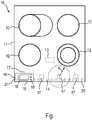
- the figure shows a top view of a household appliance 10 with a hob 11.
- the hob 11 has a plurality of cooking zones 12.
- a control unit 13 is used to control the household appliance 10 and its cooking zones 12.
- the household appliance 10 can be operated using a removable operating unit 15 .
- the operating part 15 has a transmitter-receiver or transceiver 16 as a transmission unit.
- the household appliance 10 has a number of transceivers 17 which can set up an NFC near-field radio link with the transceiver 16 of the operating unit 15 and can use this to exchange data bidirectionally.
- a display unit 18 of the control panel 15 can display, for example, a current state or status of the household appliance 10 and its components, in particular its cooking zones 12.
- the household appliance 10 can be controlled by means of operating elements 19 .
- a maximum range R between the transceiver 16 and a transceiver 17 is four centimeters.
- the control panel 15 must be in the immediate vicinity of the household appliance 10 in order to operate it. this enables continuous monitoring of the household appliance 10 when it is being operated or manipulated.
- the transceivers 17 in the household appliance 10 are arranged sufficiently close together along a front edge 20 of the hob 11 on the operator side.
- the operating part 15 has a supply unit in the form of at least one secondary coil 21, which enables inductive energy supply. To the Inductive feeding of the operating part 15 several supply units in the form of primary coils 14 are also arranged along the edge 20 in the household appliance 10 .
- control panel 15 can be placed anywhere on the front edge 20 or edge area of the hob 11 and, firstly, be inductively fed and secondly communicate with the household appliance 10 via an NFC radio connection.
- This edge 20 or an associated edge area on the hob 11 thus represents a mounting surface for the control panel 15.
- the control panel 15 can consequently be positioned and operated freely along this edge 20, which greatly increases user-friendliness.
- the cooking zones 12 can be brought closer to the front edge 20 than before.
- the distance between the cooking zones 12 shown here only serves to better illustrate the structure of the household appliance 10.
- control panel can be additionally or alternatively powered by an accumulator or a battery.
- control panel may only be freely positionable on the hob, but not outside.
Landscapes
- Engineering & Computer Science (AREA)
- Computer Networks & Wireless Communication (AREA)
- Physics & Mathematics (AREA)
- General Physics & Mathematics (AREA)
- Induction Heating Cooking Devices (AREA)
Description
- Die Erfindung betrifft ein Haushaltsgerät, wobei das Haushaltsgerät mittels eines Bedienteils bedienbar eingerichtet ist.
- Es sind Fernbedienungen für Essen oder Waschmaschinen bekannt. Diese Fernbedienungen verfügen über eingebaute Anzeigeeinrichtungen wie z.B. Leuchtdioden zur Darstellung eines Betriebszustandes des betreffenden Geräts. Jedoch ist es beispielsweise für Kochgeräte gefordert, dass sich diese nur dann von dem Bediener manipulieren lassen, wenn der Bediener das Kochgerät unmittelbar überwachen kann, also sich in unmittelbarer Nähe des Kochgeräts befindet. Dies ist so, weil Kochfelder offene Hitzequellen darstellen, von denen grundsätzlich eine Brandgefahr ausgehen kann.
- Für Kochfelder sind abnehmbare Bedienteile bekannt, die zu ihrem Betrieb auf eine randseitige Bedienblende aufsetzbar sind, wobei das Bedienteil auf eine Aufsatzfläche in der Bedienblende lokal definiert aufsetzbar ist. Die Aufsatzfläche kann z.B. als eine das Bedienteil aufnehmende Schale ("Cradle") ausgebildet sein.
-
US 6,198,079 B1 offenbart eine Steuerung für ein Elektrogerät mit mindestens einem in dem Gerät enthaltenen elektrischen Betriebsgerät, wobei die Steuerung mindestens ein Leistungsschaltgerät enthält. Dazu weist die Steuerung eine von dem Elektrogerät getrennte Steuereinheit auf, die drahtlos und signalübertragend mit dieser verbunden ist und im Wesentlichen den Steuer- und Regelteil für das Elektrogerät enthält. Auf diese Weise wird eine vom Elektrogerät getrennte oder trennbare Bedien- und Steuereinheit erhalten, die bei Bedarf als separates Teil ausgetauscht werden kann. Eine Basisversion eines Elektrogeräts kann mit verschiedenen Steuergeräten zu einem Endgerät mit unterschiedlichem Betriebsumfang aufgerüstet werden. Vorzugsweise ist das Elektrogerät ein Elektroherd, insbesondere ein Kochfeld. Als weitere Funktion muss das externe Steuergerät in einer bestimmten Position, insbesondere am Elektrogerät, angebracht werden, um den Betrieb zu ermöglichen. -
US 2011/0095873 A1 offenbart ein Verfahren und ein System zum Konfigurieren einer universellen Fernbedienung (URC) zum Steuern eines ferngesteuerten Geräts. Dies umfasst das Herstellen einer Kommunikationsverbindung zwischen dem URC und dem ferngesteuerten Gerät als Reaktion auf das Erfassen einer Gestenbewegung des URC. Geräteinformationen können vom ferngesteuerten Gerät empfangen und vom URC verwendet werden, um den URC zur Steuerung des ferngesteuerten Geräts zu programmieren. Der URC kann so konfiguriert sein, dass er mehrere ferngesteuerte Geräte steuert. Die Kommunikationsverbindung kann eine drahtlose Nahfeldkommunikationsverbindung sein. -
US 2008/0088474 A1 offenbart, dass Steuerinformationen zwischen einer Komponente und einem Fernbedienungsgerät unter Verwendung von RFID ausgetauscht und dann unter Verwendung von RFID an ein Fernsehgerät übertragen werden, so dass das Fernsehgerät zu steuernde Komponenten und / oder Tasten von Fernbedienungsgeräten und / oder Funktionen von Fernbedienungsgerätetasten anzeigen kann, um den Benutzer zu schulen. -
WO 2010/008251 A2 offenbart eine Vorrichtung zum Steuern einer Leistung und ein Verfahren davon. Ein Verfahren zum Steuern einer Stromversorgung eines Geräts, einschließlich eines Gerätehosts und eines NFC-Controllers, empfängt einen Befehl von einer externen Quelle im NFC-Controller, wobei der Befehl, der angibt, ob ein- oder ausgeschaltet werden soll, einen Stromsteuerungsbefehl an den Gerätehost sendet, der angibt, ob ein- oder ausgeschaltet werden soll, und ein Ereignis empfängt, das auf den Stromsteuerungsbefehl vom Gerätehost reagiert, wobei das Ereignis das Erreichen des Stromsteuerungsbefehls anzeigt. -
EP2385312 A2 offenbart ein Haushaltsgerät in Form einer Haushaltsarbeitsstation mit mehreren mit mehreren transformatorisch arbeitenden Basisstationen die jeweilige Primärspulen aufweisen. Die Basisstationen dienen als jeweilige Aufsatzflächen zur Energieversorgung entsprechender elektrisch betriebener Aufsatzgeräte ausschließlich mittels transformatorischer Energieübertragung. Jede der Aufsatzflächen weist genau eine Übertragungseinheit auf, die für die Kommunikation nur mit einem an dieser Aufsatzfläche angeordneten Aufsatzgerät eingerichtet ist. - Es ist die Aufgabe der vorliegenden Erfindung, eine verbesserte Bedienbarkeit eines Haushaltsgeräts bereitzustellen.
- Diese Aufgabe wird gemäß den Merkmalen des Anspruchs 1 gelöst. Bevorzugte Ausführungsformen sind insbesondere den abhängigen Ansprüchen entnehmbar. Die Aufgabe wird gelöst mittels eines Haushaltsgeräts, das als ein Kochgerät ausgebildet ist und eine Aufsatzfläche für ein Bedienteil aufweist, die sich über einen vorderen Randbereich des Haushaltsgeräts erstreckt, wobei neben oder unterhalb der Aufsatzfläche mehrere Übertragungseinheiten (insbesondere Empfänger oder Transceiver bzw. Senderempfänger) zum Aufbau einer Datenübertragung mit einer Nahfeld-Funkverbindung in Form einer NFC-Funkverbindung von dem Bedienteil oder von und zu dem Bedienteil zur Bedienung des Haushaltsgeräts angeordnet sind.
- Bereitgestellt wird dadurch eine hochgradig störungsfreie Bedienung des Haushaltsgeräts mit einer derart beschränkten Reichweite, dass ein Bediener sich in unmittelbarer Nähe zu dem zu bedienenden Haushaltsgerät befinden muss, um dieses über das Bedienteil zu bedienen. Dadurch wird verhindert, dass das Haushaltsgerät unbeaufsichtigt verstellbar ist. Somit ist eine derart bereitgestellte Fernbedienung auch bei Haushaltsgeräten einsetzbar, welche keine oder eine nur beschränkte Benutzung von Fernbedienungen zulassen. Außerdem muss das Bedienteil nicht exakt auf eine bestimmte vorgegebene Position gesetzt werden, um verwendet werden zu können. Da das Bedienteil abnehmbar ist (also nicht fest mit dem Haushaltsgerät verbunden ist), lässt sich zudem eine sehr effektive Kindersicherung erreichen.
- Eine Datenübertragung zwischen dem Bedienteil und dem Haushaltsgerät ist also mittels einer NFC-Kommunikation durchführbar. Dabei ist die maximale Reichweite auf wenige Zentimeter beschränkt. Durch die kurze Reichweite der Datenübertragung wird die Wahrscheinlichkeit verringert, dass die Datenkommunikation andere Datenübertragungen stören kann. Insbesondere wird aber sichergestellt, dass ein Benutzer das Haushaltsgerät überwachen und unmittelbar (ohne Verzögerung) bedienen kann, beispielsweise im Gegensatz zu einer Fernbedienung.
- Zudem können normgerechte NFC-Komponenten eingesetzt werden. NFC-Komponenten sind preiswert und benötigen einen nur geringen Bauraum. Unter einer NFC-Datenübertragung ("Near Field Communication") kann insbesondere die Datenübertragung gemäß dem NFC-Standard, insbesondere nach ISO-Normen, verstanden werden. Aufgrund der maximalen Reichweite der NFC-Datenübertragung von vier Zentimetern ist eine Anwesenheit des Bedieners direkt an dem Haushaltsgerät zu dessen Bedienung oder Manipulation zwingend erforderlich.
- Es ist also vorgesehen, dass das Bedienteil und das Haushaltsgerät untereinander über die NFC-Datenübertragungsmethode miteinander kommunizieren, so dass deren enge räumlich Anordnung zueinander gewährleistet ist.
- Dadurch, dass die Übertragungseinheit mehrere Übertragungseinheiten aufweist, wird bei einer maximalen Reichweite der NFC-Funkverbindung von nur wenigen Zentimetern eine Positionierbarkeit des Bedienteils auch auf einer größeren Aufsatzfläche variabel ermöglicht.
- Die Aufsatzfläche für das Bedienteil ist folglich derart eingerichtet, dass bei einem Aufsatz des Bedienteils auf der Aufsatzfläche eine Datenübertragung zwischen dem Bedienteil und dem Haushaltsgerät mittels der NFC-Funkverbindung aufbaubar ist.
- Es ist eine Weiterbildung, dass das Bedienteil auf der Aufsatzfläche frei positionierbar ist. Die Aufsatzfläche ist also insbesondere so groß, dass durch das Bedienteil mehrere signifikant unterschiedliche Positionen auf dem Aufsatzfeld einnehmbar sind. Dadurch wird eine hohe Bedienerfreundlichkeit erreicht. Insbesondere wird ein Verschieben des Bedienteils über die Aufsatzfläche an verschiedene Positionen der Aufsatzfläche ermöglicht. Dadurch kann das Bedienteil in einem Bereich positioniert werden, in dem ein Benutzer gerade nicht hantieren muss. Die Arbeitsfläche, insbesondere der Bereich eines Kochfelds, kann besser genutzt werden. Die örtlich flexiblere Positionierbarkeit ist besonders ausgeprägt, wenn die Aufsatzfläche der Versorgungseinheit ein Vielfaches größer ist als die Kontaktfläche des Bedienteils.
- Es ist eine weitere Ausgestaltung, dass die Aufsatzfläche sich über einen vorderen, oberseitigen Randbereich des Haushaltsgeräts erstreckt. Mit anderen Worten ist das Bedienteil auf einem bedienerseitigen Randbereich insbesondere eines Kochfelds positionierbar.
- Es ist noch eine Ausgestaltung, dass unterhalb der Aufsatzfläche mindestens eine induktive Versorgungseinheit zum Versorgen des Bedienteils mit Energie angeordnet ist. Dies ermöglicht eine besonders einfache Energieversorgung eines induktiv speisbaren Bedienteils. Die Versorgungseinheit weist dazu beispielsweise mindestens eine unterhalb der Aufsatzfläche angeordnete Spule auf, wodurch das Bedienteil auf der Aufsatzfläche in zumindest einem solchen Bereich mit Spulen variabel positionierbar ist. Eine induktive Versorgung des mindestens einen Bedienteils kann z.B. mittels eines Dauerbetriebs mindestens einer in der Versorgungseinheit vorhandenen Spule durchführbar sein.
- Es ist ferner eine Weiterbildung, dass eine induktive Versorgung des mindestens einen Bedienteils mittels eines Pulsbetriebs mindestens einer in der Versorgungseinheit vorhandenen Spule durchführbar ist. Grundsätzlich kann die Versorgungseinheit mit nur einer Spule ausgerüstet sein, was eine besonders preiswerte und einfach betreibbare Versorgungseinheit ermöglicht. Es ist eine für eine effektive induktive Kopplung und damit auch Energieübertragung bevorzugte Ausgestaltung, dass die Versorgungseinheit mehrere unterhalb der Aufsatzfläche angeordnete Spulen aufweist. Diese können insbesondere individuell aktiviert werden, falls an ihnen eine Last abgegriffen wird ("Aufsatzerkennung"). Insbesondere so mag eine Ausgestaltung der Spulen an eine Ausgestaltung der mindestens einen Spule des Bedienteils auf eine effektive Kopplung hin erreicht werden. Es ist eine für eine effektive induktive Kopplung besonders bevorzugte Ausgestaltung, dass die Versorgungseinheit ein Spulenfeld aufweist, d.h., ein Feld aus mehreren dicht angeordneten Spulen. Die Spulen können insbesondere in einer dichtesten Packung angeordnet sein. Die Spulen sind insbesondere kleine Spulen. Bei dieser Ausgestaltung wird auch eine über die Aufsatzfläche gleichmäßigere Feldverteilung ermöglicht als bei einer Spule oder mehreren signifikant beabstandeten Spulen. Zudem können die Spulen dann bei mehreren auf der Aufsatzfläche angelegten Bedienteilen individuell auf das jeweils mit ihnen gekoppelte Bedienteil abgestimmt betrieben werden.
- Die Versorgungseinheit ist aber auch von dem durch das Bedienteil zu bedienenden Haushaltsgerät entfernt anordenbar. Das Bedienteil kann dann bei einem Betrieb des Haushaltsgeräts auch neben dem Haushaltsgerät angeordnet sein, und zwar ohne weitere Maßnahmen maximal in einem Abstand zu dem Haushaltsgerät, welcher der maximalen Reichweite der NFC-Funkverbindung entspricht.
- Die Aufgabe wird zudem gelöst durch ein System aus dem Haushaltsgerät wie oben beschrieben und einem Bedienteil, daszum Datenaustausch mit dem Haushaltsgerät über eine NFC-Funkverbindung eingerichtet ist. Das System kann analog zu dem Haushaltsgerät ausgestaltet sein und insbesondere die gleichen Vorteile aufweisen.
- Es ist eine Ausgestaltung, dass die Datenübertragung und damit die NFC-Funkverbindung optional nicht nur unidirektional, sondern auch für eine bidirektionale Übertragung ausgelegt sind und dass das Bedienteil eine Anzeigeeinheit aufweist. Durch eine solche bidirektionale Datenübertragung wird eine Übertragung von Zustands- oder Statusinformation von dem Haushaltsgerät auf das Bedienteil realisierbar, um sie an dem Bedienteil anzuzeigen, z.B. momentan eingestellte Heizstufen von Kochzonen eines Kochgeräts.
- Es ist noch eine Weiterbildung, dass das Bedienteil induktiv oder transformatorisch speisbar ist. Dies ermöglicht, dass die Bedieneinrichtung batterielos und akkumulatorlos ist. Dadurch wird ein wartungsfreies und besonders preiswertes Bedienteil bereitgestellt. Dies schließt jedoch nicht aus, dass ein so versorgbarer bzw. speisbarer oder anders aufladbarer Akkumulator oder eine andere Energiequelle wie z.B. eine Batterie, Superkondensator oder Ultrakondensator oder Solarzelle zur Energieversorgung in dem Bedienteil angeordnet ist. Die Bedieneinrichtung kann dazu insbesondere mindestens eine Sekundärspule oder Abnehmerspule aufweisen.
- Es ist eine Weiterbildung, dass das Bedienteil mindestens eine Übertragungseinheit (insbesondere Sender oder Transceiver bzw. Senderempfänger) zum Aufbauen einer Datenübertragung mit NFC-Funkverbindung von dem Bedienteil oder von und zu dem Bedienteil aufweist.
- Insbesondere kann eine solche Fernbedienung auch zum Bedienen weiterer, z.B. aller Geräte in der Küche einsetzbar sein.
- In der folgenden Figur wird die Erfindung anhand von Ausführungsbeispielen schematisch genauer beschrieben. Dabei können zur Übersichtlichkeit gleiche oder gleichwirkende Elemente mit gleichen Bezugszeichen versehen sein.
- Die Fig. zeigt in Draufsicht ein Haushaltsgerät 10 mit einem Kochfeld 11. Das Kochfeld 11 weist mehrere Kochzonen 12 auf. Zur Steuerung des Haushaltsgeräts 10 und seiner Kochzonen 12 dient eine Steuereinheit 13.
- Das Haushaltsgerät 10 ist mittels eines abnehmbaren Bedienteils 15 bedienbar. Das Bedienteil 15 weist als Übertragungseinheit einen Senderempfänger oder Transceiver 16 auf. Das Haushaltsgerät 10 weist mehrere Transceiver 17 auf, die mit dem Transceiver 16 des Bedienteils 15 eine NFC-Nahfeld-Funkverbindung aufbauen können und darüber Daten bidirektional austauschen können. Dadurch kann auf einer Anzeigeeinheit 18 des Bedienteils 15 z.B. ein momentaner Zustand oder Status des Haushaltsgeräts 10 und seiner Komponenten, insbesondere seiner Kochzonen 12, angezeigt werden. Mittels Bedienelementen 19 ist das Haushaltsgerät 10 ansteuerbar.
- Aufgrund der NFC-Funkverbindung beträgt eine maximale Reichweite R zwischen dem Transceiver 16 und einem Transceiver 17 vier Zentimeter. Dadurch muss das Bedienteil 15 sich zur Bedienung des Haushaltsgeräts 10 in dessen unmittelbarer Nähe befinden. so wird eine dauernde Überwachung des Haushaltsgeräts 10 bei dessen Bedienung oder Manipulation ermöglicht. Die Transceiver 17 im Haushaltsgerät 10 sind ausreichend dicht entlang eines vorderen, bedienerseitigen Rands 20 des Kochfelds 11 angeordnet.
- Das Bedienteil 15 weist zur Energieversorgung eine Versorgungseinheit in Form mindestens einer Sekundärspule 21 auf, welche eine induktive Energiezufuhr ermöglicht. Zur induktiven Speisung des Bedienteils 15 sind in dem Haushaltsgerät 10 ebenfalls entlang des Rands 20 mehrere Versorgungseinheiten in Form von Primärspulen 14 angeordnet.
- Folglich kann das Bedienteil 15 an beliebiger Stelle auf dem vorderen Rand 20 bzw. Randbereich des Kochfelds 11 aufgesetzt werden und dabei erstens induktiv gespeist werden und zweiten über eine NFC-Funkverbindung mit dem Haushaltsgerät 10 kommunizieren. Dieser Rand 20 bzw. ein zugehöriger Randbereich auf dem Kochfeld 11 stellt somit eine Aufsatzfläche für das Bedienteil 15 dar. Das Bedienteil 15 ist folglich entlang dieses Rands 20 frei positionierbar und bedienbar, was eine Bedienerfreundlichkeit stark erhöht.
- Durch die Auslagerung der Anzeigeeinheit 18, Bedienelemente 19 und insbesondere einer Bedienelektronik (o.Abb.) aus dem Haushaltsgerät 10 in das Bedienteil 15 können die Kochzonen 12 näher an den vorderen Rand 20 herangebracht werden als bisher. Der hier gezeigte Abstand der Kochzonen 12 dient lediglich der besseren Darstellung des Aufbaus des Haushaltsgeräts 10.
- Selbstverständlich ist die vorliegende Erfindung nicht auf die gezeigten Ausführungsbeispiele beschränkt.
- So kann das Bedienteil zusätzlich oder alternativ mittels eines Akkumulators oder einer Batterie versorgt werden. In einer weiteren Variante mag das Bedienteil nur auf dem Kochfeld frei positionierbar sein, aber nicht außerhalb.
-
- 10
- Haushaltsgerät
- 11
- Kochfeld
- 12
- Kochzone
- 13
- Steuereinheit
- 14
- Primärspule
- 15
- Bedienteil
- 16
- Transceiver im Bedienteil
- 17
- Transceiver im Haushaltsgerät
- 18
- Anzeigeeinheit
- 19
- Bedienelement
- 20
- Rand
- 21
- Sekundärspule
- R
- maximale Reichweite
Claims (6)
- Haushaltsgerät (10), das- als ein Kochgerät ausgebildet ist und- eine Aufsatzfläche (20) für ein Bedienteil (15) aufweist, die sich über einen vorderen Randbereich des Haushaltsgeräts (10) erstreckt,- das Kochgerät in Form eines Kochfelds (11) mit mehreren Kochzonen (12) ausgebildet ist,dadurch gekennzeichnet, dass- sich die Aufsatzfläche (20) nur entlang des gesamten vorderen Randbereichs des Haushaltsgeräts (10) erstreckt,- neben oder unterhalb der Aufsatzfläche (20) mehrere Übertragungseinheiten (17) zum Aufbau einer Datenübertragung mittels einer NFC-Funkverbindung von dem Bedienteil (15) oder von und zu dem Bedienteil (15) zur Bedienung des Haushaltsgeräts (10) angeordnet sind und- zur induktiven Speisung des Bedienteils (15) entlang des gesamten vorderen Randbereichs mehrere Versorgungseinheiten in Form von Primärspulen (14) angeordnet sind, so dass- das Bedienteil (15) an beliebiger Stelle auf dem vorderen Randbereich aufgesetzt werden und dabei induktiv gespeist werden und über eine NFC-Funkverbindung mit dem Haushaltsgerät (10) kommunizieren kann.
- Haushaltsgerät (10) nach Anspruch 1, dadurch gekennzeichnet, dass die Primärspulen (14) individuell aktiviert werden, falls an ihnen eine Last abgegriffen wird.
- Haushaltsgerät (10) nach einem der vorhergehenden Ansprüche, dadurch gekennzeichnet, dass die Primärspulen (14) in einer Reihe angeordnet sind.
- System mit einem Haushaltsgerät und einem Bedienteil, dadurch gekennzeichnet, dass das Haushaltsgerät ein Haushaltsgerät (10) nach einem der Ansprüche 1 bis 3 ist und das Bedienteil (15) zur Bedienung des Haushaltsgeräts (10) mittels Datenaustauschs mit dem Haushaltsgerät (10) über eine NFC-Funkverbindung eingerichtet ist.
- System nach Anspruch 4, dadurch gekennzeichnet, dass die NFC-Funkverbindung für eine bidirektionale Übertragung ausgelegt ist und das Bedienteil (15) eine Anzeigeeinheit (18) aufweist.
- System nach einem der Ansprüche 4 bis 5, dadurch gekennzeichnet, dass das Bedienteil (15) induktiv speisbar ist.
Applications Claiming Priority (1)
| Application Number | Priority Date | Filing Date | Title |
|---|---|---|---|
| DE102012210855.6A DE102012210855A1 (de) | 2012-06-26 | 2012-06-26 | Bedienteil für ein Haushaltsgerät |
Publications (2)
| Publication Number | Publication Date |
|---|---|
| EP2680246A1 EP2680246A1 (de) | 2014-01-01 |
| EP2680246B1 true EP2680246B1 (de) | 2022-11-30 |
Family
ID=48669770
Family Applications (1)
| Application Number | Title | Priority Date | Filing Date |
|---|---|---|---|
| EP13172236.5A Active EP2680246B1 (de) | 2012-06-26 | 2013-06-17 | Haushaltsgerät |
Country Status (2)
| Country | Link |
|---|---|
| EP (1) | EP2680246B1 (de) |
| DE (1) | DE102012210855A1 (de) |
Families Citing this family (3)
| Publication number | Priority date | Publication date | Assignee | Title |
|---|---|---|---|---|
| DE102014215705A1 (de) | 2014-08-07 | 2016-02-11 | BSH Hausgeräte GmbH | Kochgerät mit Nahfeldantennen |
| DE102016209133A1 (de) * | 2016-05-25 | 2017-11-30 | BSH Hausgeräte GmbH | Gargerät mit Nahbereichs-Funkschnittstelle |
| DE102018209518A1 (de) | 2018-06-14 | 2019-12-19 | BSH Hausgeräte GmbH | Gargerät mit einem Netzanschluss und einem daran angeordneten Funkmodul |
Citations (2)
| Publication number | Priority date | Publication date | Assignee | Title |
|---|---|---|---|---|
| WO2010008251A2 (en) * | 2008-07-18 | 2010-01-21 | Lg Electronics Inc. | Apparatus for controlling a power and method thereof |
| EP2385312A2 (de) * | 2010-05-03 | 2011-11-09 | BSH Bosch und Siemens Hausgeräte GmbH | Bedienteil für eine Haushaltsarbeitsstation, Haushaltsarbeitsstation, System aus Haushaltsarbeitsstation und Bedienteil sowie Verfahren zum Betreiben des Systems |
Family Cites Families (8)
| Publication number | Priority date | Publication date | Assignee | Title |
|---|---|---|---|---|
| DE19849075A1 (de) * | 1998-10-24 | 2000-04-27 | Ego Elektro Geraetebau Gmbh | Steuerung für ein Elektrogerät |
| DE10254152A1 (de) * | 2002-11-20 | 2004-06-03 | BSH Bosch und Siemens Hausgeräte GmbH | Verfahren zum Datenaustausch zwischen einem elektrischen Gerät und einer Benutzerschnittstelle über ein Datennetz |
| US7952467B2 (en) * | 2006-09-29 | 2011-05-31 | Sony Corporation | System and method for informing user how to use universal remote control |
| DE102009000909B4 (de) * | 2009-02-17 | 2020-01-23 | BSH Hausgeräte GmbH | Anordnung zur Zubereitung von Lebensmitteln |
| DE102009002774A1 (de) * | 2009-04-30 | 2010-11-04 | BSH Bosch und Siemens Hausgeräte GmbH | Verfahren zum Betreiben eines Haushaltsgeräts, portable Bedieneinheit und Haushaltsgerät |
| US8665075B2 (en) * | 2009-10-26 | 2014-03-04 | At&T Intellectual Property I, L.P. | Gesture-initiated remote control programming |
| DE102010028493A1 (de) * | 2010-05-03 | 2011-11-03 | BSH Bosch und Siemens Hausgeräte GmbH | Bedienteil für eine Haushaltsarbeitsstation, Haushaltsarbeitsstation sowie System aus der Haushaltsarbeitsstation und dem Bedienteil |
| DE102010039058A1 (de) * | 2010-08-09 | 2012-02-09 | BSH Bosch und Siemens Hausgeräte GmbH | Hausgerät zum Zubereiten von Lebensmitteln mit einer Kommunikationsschnittstelle |
-
2012
- 2012-06-26 DE DE102012210855.6A patent/DE102012210855A1/de not_active Withdrawn
-
2013
- 2013-06-17 EP EP13172236.5A patent/EP2680246B1/de active Active
Patent Citations (2)
| Publication number | Priority date | Publication date | Assignee | Title |
|---|---|---|---|---|
| WO2010008251A2 (en) * | 2008-07-18 | 2010-01-21 | Lg Electronics Inc. | Apparatus for controlling a power and method thereof |
| EP2385312A2 (de) * | 2010-05-03 | 2011-11-09 | BSH Bosch und Siemens Hausgeräte GmbH | Bedienteil für eine Haushaltsarbeitsstation, Haushaltsarbeitsstation, System aus Haushaltsarbeitsstation und Bedienteil sowie Verfahren zum Betreiben des Systems |
Also Published As
| Publication number | Publication date |
|---|---|
| EP2680246A1 (de) | 2014-01-01 |
| DE102012210855A1 (de) | 2014-01-02 |
Similar Documents
| Publication | Publication Date | Title |
|---|---|---|
| EP3489583B1 (de) | Verfahren zur steuerung eines kochgeräts mit einem externen steuergerät, kochgerät und system | |
| EP2425182B1 (de) | Verfahren zum betreiben eines haushaltsgeräts | |
| EP2834567B1 (de) | Kochfeld und verfahren zur steuerung eines kochfeldes | |
| EP1001321B1 (de) | Steuerung für ein Elektrogerät | |
| EP3416457B1 (de) | Verfahren zum betrieb eines induktiven kochsystems | |
| DE102016206912B4 (de) | Verfahren zur Steuerung eines Kochgerätes und Kochgerät | |
| EP3272467B1 (de) | Adapteranordnungssystem | |
| EP2679910B1 (de) | Haushaltsgerät mit Bedineeinrichtung | |
| EP2385312B1 (de) | System aufweisend eine haushaltsarbeitsstation mit einem bedienteil, sowie verfahren zum betreiben des systems | |
| DE102013214929B4 (de) | Verfahren und Anordnung zum Steuern eines Gargeräts | |
| WO2010130587A1 (de) | Portable, insbesondere medienfähige konsole | |
| DE102013114050B4 (de) | Werkzeugsteuerung | |
| DE102006007169A1 (de) | Vorrichtung und Verfahren zum Betrieb eines Elektrogerätes mit einer außen ansetzbaren Bedieneinrichtung | |
| EP2680246B1 (de) | Haushaltsgerät | |
| DE102019202991A1 (de) | Verfahren zur Ansteuerung einer Induktionsspule und Induktionsspulenvorrichtung | |
| DE102014215705A1 (de) | Kochgerät mit Nahfeldantennen | |
| EP2385311A2 (de) | Bedienteil für eine Haushaltsarbeitsstation, Haushaltsarbeitsstation sowie System aus der Haushaltsarbeitsstation und dem Bedienteil | |
| EP2456039A2 (de) | Haushaltsgerät und Verfahren zum Betreiben eines Haushaltsgeräts | |
| EP3890438A1 (de) | Verfahren zum beheizen eines kochgefässes auf einem kochfeld und kochfeld | |
| EP2048913A2 (de) | Induktionsmodul, Anordnung mehrerer Induktionsmodule und Verfahren zur Einrichtung eines solchen Induktionsmoduls | |
| EP3974939A1 (de) | Haushaltgerät und verfahren zum betreiben | |
| DE102006038412B4 (de) | Kochmulde mit wenigstens einer Bedienelementenanordnung | |
| WO2018196941A1 (de) | Haushaltsgerät und bedienvorrichtung für ein hauhaltsgerät | |
| DE202019101157U1 (de) | Steuerungs- und Kontrollsystem für ein Kochfeld | |
| WO2018104066A1 (de) | Haushaltsgerät, bedienelement für ein haushaltsgerät und verfahren zum steuern eines haushaltsgeräts |
Legal Events
| Date | Code | Title | Description |
|---|---|---|---|
| PUAI | Public reference made under article 153(3) epc to a published international application that has entered the european phase |
Free format text: ORIGINAL CODE: 0009012 |
|
| AK | Designated contracting states |
Kind code of ref document: A1 Designated state(s): AL AT BE BG CH CY CZ DE DK EE ES FI FR GB GR HR HU IE IS IT LI LT LU LV MC MK MT NL NO PL PT RO RS SE SI SK SM TR |
|
| AX | Request for extension of the european patent |
Extension state: BA ME |
|
| 17P | Request for examination filed |
Effective date: 20140701 |
|
| RBV | Designated contracting states (corrected) |
Designated state(s): AL AT BE BG CH CY CZ DE DK EE ES FI FR GB GR HR HU IE IS IT LI LT LU LV MC MK MT NL NO PL PT RO RS SE SI SK SM TR |
|
| RAP1 | Party data changed (applicant data changed or rights of an application transferred) |
Owner name: BSH HAUSGERAETE GMBH |
|
| STAA | Information on the status of an ep patent application or granted ep patent |
Free format text: STATUS: EXAMINATION IS IN PROGRESS |
|
| 17Q | First examination report despatched |
Effective date: 20180312 |
|
| STAA | Information on the status of an ep patent application or granted ep patent |
Free format text: STATUS: EXAMINATION IS IN PROGRESS |
|
| STAA | Information on the status of an ep patent application or granted ep patent |
Free format text: STATUS: EXAMINATION IS IN PROGRESS |
|
| GRAP | Despatch of communication of intention to grant a patent |
Free format text: ORIGINAL CODE: EPIDOSNIGR1 |
|
| STAA | Information on the status of an ep patent application or granted ep patent |
Free format text: STATUS: GRANT OF PATENT IS INTENDED |
|
| INTG | Intention to grant announced |
Effective date: 20220719 |
|
| GRAS | Grant fee paid |
Free format text: ORIGINAL CODE: EPIDOSNIGR3 |
|
| GRAA | (expected) grant |
Free format text: ORIGINAL CODE: 0009210 |
|
| STAA | Information on the status of an ep patent application or granted ep patent |
Free format text: STATUS: THE PATENT HAS BEEN GRANTED |
|
| AK | Designated contracting states |
Kind code of ref document: B1 Designated state(s): AL AT BE BG CH CY CZ DE DK EE ES FI FR GB GR HR HU IE IS IT LI LT LU LV MC MK MT NL NO PL PT RO RS SE SI SK SM TR |
|
| REG | Reference to a national code |
Ref country code: CH Ref legal event code: EP Ref country code: GB Ref legal event code: FG4D Free format text: NOT ENGLISH |
|
| REG | Reference to a national code |
Ref country code: AT Ref legal event code: REF Ref document number: 1535263 Country of ref document: AT Kind code of ref document: T Effective date: 20221215 Ref country code: DE Ref legal event code: R096 Ref document number: 502013016299 Country of ref document: DE |
|
| REG | Reference to a national code |
Ref country code: IE Ref legal event code: FG4D Free format text: LANGUAGE OF EP DOCUMENT: GERMAN |
|
| REG | Reference to a national code |
Ref country code: LT Ref legal event code: MG9D |
|
| REG | Reference to a national code |
Ref country code: NL Ref legal event code: MP Effective date: 20221130 |
|
| PG25 | Lapsed in a contracting state [announced via postgrant information from national office to epo] |
Ref country code: SE Free format text: LAPSE BECAUSE OF FAILURE TO SUBMIT A TRANSLATION OF THE DESCRIPTION OR TO PAY THE FEE WITHIN THE PRESCRIBED TIME-LIMIT Effective date: 20221130 Ref country code: PT Free format text: LAPSE BECAUSE OF FAILURE TO SUBMIT A TRANSLATION OF THE DESCRIPTION OR TO PAY THE FEE WITHIN THE PRESCRIBED TIME-LIMIT Effective date: 20230331 Ref country code: NO Free format text: LAPSE BECAUSE OF FAILURE TO SUBMIT A TRANSLATION OF THE DESCRIPTION OR TO PAY THE FEE WITHIN THE PRESCRIBED TIME-LIMIT Effective date: 20230228 Ref country code: LT Free format text: LAPSE BECAUSE OF FAILURE TO SUBMIT A TRANSLATION OF THE DESCRIPTION OR TO PAY THE FEE WITHIN THE PRESCRIBED TIME-LIMIT Effective date: 20221130 Ref country code: FI Free format text: LAPSE BECAUSE OF FAILURE TO SUBMIT A TRANSLATION OF THE DESCRIPTION OR TO PAY THE FEE WITHIN THE PRESCRIBED TIME-LIMIT Effective date: 20221130 Ref country code: ES Free format text: LAPSE BECAUSE OF FAILURE TO SUBMIT A TRANSLATION OF THE DESCRIPTION OR TO PAY THE FEE WITHIN THE PRESCRIBED TIME-LIMIT Effective date: 20221130 |
|
| PG25 | Lapsed in a contracting state [announced via postgrant information from national office to epo] |
Ref country code: RS Free format text: LAPSE BECAUSE OF FAILURE TO SUBMIT A TRANSLATION OF THE DESCRIPTION OR TO PAY THE FEE WITHIN THE PRESCRIBED TIME-LIMIT Effective date: 20221130 Ref country code: PL Free format text: LAPSE BECAUSE OF FAILURE TO SUBMIT A TRANSLATION OF THE DESCRIPTION OR TO PAY THE FEE WITHIN THE PRESCRIBED TIME-LIMIT Effective date: 20221130 Ref country code: LV Free format text: LAPSE BECAUSE OF FAILURE TO SUBMIT A TRANSLATION OF THE DESCRIPTION OR TO PAY THE FEE WITHIN THE PRESCRIBED TIME-LIMIT Effective date: 20221130 Ref country code: IS Free format text: LAPSE BECAUSE OF FAILURE TO SUBMIT A TRANSLATION OF THE DESCRIPTION OR TO PAY THE FEE WITHIN THE PRESCRIBED TIME-LIMIT Effective date: 20230330 Ref country code: HR Free format text: LAPSE BECAUSE OF FAILURE TO SUBMIT A TRANSLATION OF THE DESCRIPTION OR TO PAY THE FEE WITHIN THE PRESCRIBED TIME-LIMIT Effective date: 20221130 Ref country code: GR Free format text: LAPSE BECAUSE OF FAILURE TO SUBMIT A TRANSLATION OF THE DESCRIPTION OR TO PAY THE FEE WITHIN THE PRESCRIBED TIME-LIMIT Effective date: 20230301 |
|
| PG25 | Lapsed in a contracting state [announced via postgrant information from national office to epo] |
Ref country code: NL Free format text: LAPSE BECAUSE OF FAILURE TO SUBMIT A TRANSLATION OF THE DESCRIPTION OR TO PAY THE FEE WITHIN THE PRESCRIBED TIME-LIMIT Effective date: 20221130 |
|
| PG25 | Lapsed in a contracting state [announced via postgrant information from national office to epo] |
Ref country code: SM Free format text: LAPSE BECAUSE OF FAILURE TO SUBMIT A TRANSLATION OF THE DESCRIPTION OR TO PAY THE FEE WITHIN THE PRESCRIBED TIME-LIMIT Effective date: 20221130 Ref country code: RO Free format text: LAPSE BECAUSE OF FAILURE TO SUBMIT A TRANSLATION OF THE DESCRIPTION OR TO PAY THE FEE WITHIN THE PRESCRIBED TIME-LIMIT Effective date: 20221130 Ref country code: EE Free format text: LAPSE BECAUSE OF FAILURE TO SUBMIT A TRANSLATION OF THE DESCRIPTION OR TO PAY THE FEE WITHIN THE PRESCRIBED TIME-LIMIT Effective date: 20221130 Ref country code: DK Free format text: LAPSE BECAUSE OF FAILURE TO SUBMIT A TRANSLATION OF THE DESCRIPTION OR TO PAY THE FEE WITHIN THE PRESCRIBED TIME-LIMIT Effective date: 20221130 Ref country code: CZ Free format text: LAPSE BECAUSE OF FAILURE TO SUBMIT A TRANSLATION OF THE DESCRIPTION OR TO PAY THE FEE WITHIN THE PRESCRIBED TIME-LIMIT Effective date: 20221130 |
|
| PG25 | Lapsed in a contracting state [announced via postgrant information from national office to epo] |
Ref country code: SK Free format text: LAPSE BECAUSE OF FAILURE TO SUBMIT A TRANSLATION OF THE DESCRIPTION OR TO PAY THE FEE WITHIN THE PRESCRIBED TIME-LIMIT Effective date: 20221130 Ref country code: AL Free format text: LAPSE BECAUSE OF FAILURE TO SUBMIT A TRANSLATION OF THE DESCRIPTION OR TO PAY THE FEE WITHIN THE PRESCRIBED TIME-LIMIT Effective date: 20221130 |
|
| REG | Reference to a national code |
Ref country code: DE Ref legal event code: R097 Ref document number: 502013016299 Country of ref document: DE |
|
| PLBE | No opposition filed within time limit |
Free format text: ORIGINAL CODE: 0009261 |
|
| STAA | Information on the status of an ep patent application or granted ep patent |
Free format text: STATUS: NO OPPOSITION FILED WITHIN TIME LIMIT |
|
| PGFP | Annual fee paid to national office [announced via postgrant information from national office to epo] |
Ref country code: GB Payment date: 20230622 Year of fee payment: 11 |
|
| 26N | No opposition filed |
Effective date: 20230831 |
|
| PG25 | Lapsed in a contracting state [announced via postgrant information from national office to epo] |
Ref country code: SI Free format text: LAPSE BECAUSE OF FAILURE TO SUBMIT A TRANSLATION OF THE DESCRIPTION OR TO PAY THE FEE WITHIN THE PRESCRIBED TIME-LIMIT Effective date: 20221130 |
|
| PG25 | Lapsed in a contracting state [announced via postgrant information from national office to epo] |
Ref country code: MC Free format text: LAPSE BECAUSE OF FAILURE TO SUBMIT A TRANSLATION OF THE DESCRIPTION OR TO PAY THE FEE WITHIN THE PRESCRIBED TIME-LIMIT Effective date: 20221130 |
|
| PG25 | Lapsed in a contracting state [announced via postgrant information from national office to epo] |
Ref country code: MC Free format text: LAPSE BECAUSE OF FAILURE TO SUBMIT A TRANSLATION OF THE DESCRIPTION OR TO PAY THE FEE WITHIN THE PRESCRIBED TIME-LIMIT Effective date: 20221130 |
|
| REG | Reference to a national code |
Ref country code: CH Ref legal event code: PL |
|
| REG | Reference to a national code |
Ref country code: BE Ref legal event code: MM Effective date: 20230630 |
|
| PG25 | Lapsed in a contracting state [announced via postgrant information from national office to epo] |
Ref country code: LU Free format text: LAPSE BECAUSE OF NON-PAYMENT OF DUE FEES Effective date: 20230617 |
|
| REG | Reference to a national code |
Ref country code: IE Ref legal event code: MM4A |
|
| PG25 | Lapsed in a contracting state [announced via postgrant information from national office to epo] |
Ref country code: LU Free format text: LAPSE BECAUSE OF NON-PAYMENT OF DUE FEES Effective date: 20230617 |
|
| PG25 | Lapsed in a contracting state [announced via postgrant information from national office to epo] |
Ref country code: IE Free format text: LAPSE BECAUSE OF NON-PAYMENT OF DUE FEES Effective date: 20230617 |
|
| PG25 | Lapsed in a contracting state [announced via postgrant information from national office to epo] |
Ref country code: IE Free format text: LAPSE BECAUSE OF NON-PAYMENT OF DUE FEES Effective date: 20230617 Ref country code: CH Free format text: LAPSE BECAUSE OF NON-PAYMENT OF DUE FEES Effective date: 20230630 |
|
| PG25 | Lapsed in a contracting state [announced via postgrant information from national office to epo] |
Ref country code: IT Free format text: LAPSE BECAUSE OF FAILURE TO SUBMIT A TRANSLATION OF THE DESCRIPTION OR TO PAY THE FEE WITHIN THE PRESCRIBED TIME-LIMIT Effective date: 20221130 Ref country code: FR Free format text: LAPSE BECAUSE OF NON-PAYMENT OF DUE FEES Effective date: 20230630 Ref country code: BE Free format text: LAPSE BECAUSE OF NON-PAYMENT OF DUE FEES Effective date: 20230630 |
|
| PGFP | Annual fee paid to national office [announced via postgrant information from national office to epo] |
Ref country code: DE Payment date: 20240630 Year of fee payment: 12 |
|
| REG | Reference to a national code |
Ref country code: AT Ref legal event code: MM01 Ref document number: 1535263 Country of ref document: AT Kind code of ref document: T Effective date: 20230617 |