EP2680246A1 - Bedienteil für ein Haushaltsgerät - Google Patents
Bedienteil für ein Haushaltsgerät Download PDFInfo
- Publication number
- EP2680246A1 EP2680246A1 EP13172236.5A EP13172236A EP2680246A1 EP 2680246 A1 EP2680246 A1 EP 2680246A1 EP 13172236 A EP13172236 A EP 13172236A EP 2680246 A1 EP2680246 A1 EP 2680246A1
- Authority
- EP
- European Patent Office
- Prior art keywords
- household appliance
- control panel
- radio link
- control unit
- domestic appliance
- Prior art date
- Legal status (The legal status is an assumption and is not a legal conclusion. Google has not performed a legal analysis and makes no representation as to the accuracy of the status listed.)
- Granted
Links
- 230000005540 biological transmission Effects 0.000 claims abstract description 27
- 238000010411 cooking Methods 0.000 claims description 13
- 230000001939 inductive effect Effects 0.000 claims description 8
- 230000002457 bidirectional effect Effects 0.000 claims description 2
- 238000004891 communication Methods 0.000 description 3
- 230000008878 coupling Effects 0.000 description 3
- 238000010168 coupling process Methods 0.000 description 3
- 238000005859 coupling reaction Methods 0.000 description 3
- 238000010276 construction Methods 0.000 description 1
- 230000001419 dependent effect Effects 0.000 description 1
- 238000006073 displacement reaction Methods 0.000 description 1
- 238000010438 heat treatment Methods 0.000 description 1
- 230000002452 interceptive effect Effects 0.000 description 1
- 238000000034 method Methods 0.000 description 1
- 238000012544 monitoring process Methods 0.000 description 1
- 230000002093 peripheral effect Effects 0.000 description 1
- 238000005406 washing Methods 0.000 description 1
Images
Classifications
-
- G—PHYSICS
- G08—SIGNALLING
- G08C—TRANSMISSION SYSTEMS FOR MEASURED VALUES, CONTROL OR SIMILAR SIGNALS
- G08C17/00—Arrangements for transmitting signals characterised by the use of a wireless electrical link
- G08C17/02—Arrangements for transmitting signals characterised by the use of a wireless electrical link using a radio link
-
- G—PHYSICS
- G08—SIGNALLING
- G08C—TRANSMISSION SYSTEMS FOR MEASURED VALUES, CONTROL OR SIMILAR SIGNALS
- G08C2201/00—Transmission systems of control signals via wireless link
- G08C2201/10—Power supply of remote control devices
-
- G—PHYSICS
- G08—SIGNALLING
- G08C—TRANSMISSION SYSTEMS FOR MEASURED VALUES, CONTROL OR SIMILAR SIGNALS
- G08C2201/00—Transmission systems of control signals via wireless link
- G08C2201/50—Receiving or transmitting feedback, e.g. replies, status updates, acknowledgements, from the controlled devices
-
- G—PHYSICS
- G08—SIGNALLING
- G08C—TRANSMISSION SYSTEMS FOR MEASURED VALUES, CONTROL OR SIMILAR SIGNALS
- G08C2201/00—Transmission systems of control signals via wireless link
- G08C2201/90—Additional features
- G08C2201/91—Remote control based on location and proximity
Definitions
- the invention relates to a control unit for at least one household appliance, wherein the control panel is set up for data exchange with the household appliance via a radio link.
- the invention also relates to a household appliance, wherein the household appliance is set operable by means of such a control panel.
- Remote controls for food or washing machines are known. These remote controls have built-in display devices such as LEDs for displaying an operating state of the device in question.
- display devices such as LEDs for displaying an operating state of the device in question.
- hobs removable control units which can be placed for their operation on a peripheral control panel, the control panel is placed locally defined on a top surface in the control panel.
- the attachment surface can e.g. as a the control panel receiving shell (“Cradle”) may be formed.
- the object is achieved by means of a control panel for at least one household appliance, wherein the control panel is set up for data exchange with the household appliance via a radio link and the radio link is a near-field radio link.
- the control panel is set up for data exchange with the household appliance via a radio link and the radio link is a near-field radio link.
- control unit has at least one transmission unit (in particular transmitter or transceiver or transceiver) for establishing a data transmission with near-field radio link from the control panel or from and to the control panel.
- transmission unit in particular transmitter or transceiver or transceiver
- the near-field radio link is set up for a maximum range of 1 m, in particular 0.5 m or 0.1 m.
- a near-field radio transmission can be understood in particular to be a radio transmission which can be carried out within a centimeter range, in particular not more than about one meter, in particular not more than fifty centimeters, in particular not more than ten centimeters, in particular not more than five centimeters, especially not more than four centimeters.
- the short range of data transmission reduces the likelihood that data communication can interfere with other data transmissions. In particular, however, it is ensured that a user can monitor the household appliance and operate it immediately (without delay), for example in contrast to a remote control.
- the near-field radio link is an NFC radio link.
- a data transmission between the control unit and the household appliance can therefore be carried out by means of NFC communication.
- the maximum range is limited to a few centimeters.
- standard-compliant NFC components can be used. NFC components are inexpensive and require only a small amount of space.
- Under an NFC data transmission (“Near Field Communication") can be understood in particular the data transmission according to the NFC standard, in particular according to ISO standards. Due to the maximum range of NFC data transmission of four centimeters, a presence of the operator directly to the household appliance for its operation or manipulation is mandatory.
- control unit and the household appliance communicate with each other via near-field radio connection (s), in particular the NFC data transmission method, so that their close spatial arrangement is ensured to each other.
- s near-field radio connection
- Such data transmission may be e.g. via Bluetooth (e.g., with a maximum range of ten meters), piconet, etc.
- Other household appliances may e.g. Refrigerators, laundry appliances, small electrical appliances such as toasters, coffee makers, etc. include.
- the data transmission and thus the near-field radio link are optionally not only unidirectional, but also designed for a bidirectional transmission and that the control unit has a display unit.
- Such bi-directional data transmission makes it possible to transmit state or status information from the household appliance to the control panel for display on the control panel, e.g. Currently set heating levels of cooking zones of a cooking appliance.
- control panel is inductively or transformer fed. This allows the operating device to be batteryless and battery-less. This provides a maintenance-free and particularly inexpensive control panel. However, this does not exclude that a so-storable or otherwise rechargeable accumulator or other energy source such. a battery, supercapacitor or ultracapacitor or solar cell for power supply is arranged in the control unit.
- the operating device may for this purpose in particular have at least one secondary coil or pickup coil.
- the object is also achieved by a household appliance, wherein the household appliance with a control panel as described above is set operable.
- the household appliance can be designed analogously and in particular have the same advantages.
- the household appliance is designed as a cooking appliance.
- the household appliance has an attachment surface for the operating part in such a way that, in the case of an attachment of the operating part on the attachment surface, data transmission between the operating part and the household appliance can be established by means of the near-field radio connection.
- the control panel is freely positioned on the top surface.
- the attachment surface is thus in particular so large that a plurality of significantly different positions on the attachment field can be captured by the operating part. This achieves a high degree of user-friendliness.
- a displacement of the operating part over the attachment surface is made possible to different positions of the attachment surface.
- the work surface in particular the area of a cooktop, can be better utilized.
- the locally more flexible positioning is particularly pronounced when the top surface of the supply unit is many times larger than the contact surface of the control panel.
- the attachment surface extends over a front, in particular upper side, edge region of the household appliance.
- the operating part can be positioned on a user-side edge region, in particular of a hob.
- At least one inductive supply unit for supplying the control panel is arranged with energy below the top surface.
- the supply unit has, for example, at least one coil arranged below the top surface, as a result of which the operating part can be positioned variably on the top surface in at least one such region with coils.
- An inductive supply of the at least one control unit may e.g. be carried out by means of a continuous operation of at least one existing in the supply unit coil.
- an inductive supply of the at least one operating part can be carried out by means of a pulsed operation of at least one coil present in the supply unit.
- the supply unit with only one Spool be equipped, which allows a particularly inexpensive and easy to operate supply unit.
- the supply unit has a plurality of coils arranged below the attachment surface. In particular, these can be activated individually if a load is picked up on them ("attachment recognition").
- attachment recognition an embodiment of the coils can be achieved in an embodiment of the at least one coil of the control unit to an effective coupling out.
- the supply unit has a coil field, ie a field of a plurality of densely arranged coils.
- the coils may in particular be arranged in a densest package.
- the coils are in particular small coils.
- a more uniform over the top surface field distribution is made possible as a coil or more significantly spaced coils.
- the coils can then be operated individually tuned to the respective control unit coupled with them in case of several on the top surface applied controls.
- the supply unit can also be remotely located from the household appliance to be operated by the control unit.
- the control panel may then be arranged in an operation of the household appliance next to the household appliance, and without further measures at a maximum distance from the household appliance, which corresponds to the maximum range of the near-field radio link.
- At least one transmission unit for establishing a data transmission with near-field radio link from the control panel or from and to the control panel is present next to or below the top surface.
- the transmission unit has a plurality of transmission units in order to enable a positioning capability of the control unit to be variably also on a larger attachment surface, in particular given a maximum range of the near-field radio connection of only a few centimeters.
- such a remote control can also be used to operate other, for example, all appliances in the kitchen.
- device numbers can optionally prevent devices from different rooms from interfering, for example, through open doors.
- the object is also achieved by a system of the household appliance as described above and a control panel as described above.
- the system can be designed analogously and in particular have the same advantages.
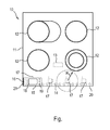
- the FIGURE shows a plan view of a household appliance 10 with a hob 11.
- the hob 11 has a plurality of cooking zones 12.
- a control unit 13th For controlling the household appliance 10 and its cooking zones 12 is a control unit 13th
- the household appliance 10 is operated by means of a removable control unit 15.
- the control unit 15 has as a transmission unit to a transceiver or transceiver 16.
- the household appliance 10 has a plurality of transceivers 17, which can build up an NFC near-field radio connection with the transceiver 16 of the control unit 15 and can exchange data bidirectionally over it.
- a display unit 18 of the operating part 15 e.g. a current state or status of the household appliance 10 and its components, in particular its cooking zones 12, are displayed.
- controls 19 the household appliance 10 is controlled.
- a maximum range R between the transceiver 16 and a transceiver 17 is a maximum of four centimeters.
- the control unit 15 must be located in the immediate vicinity for operating the household appliance 10.
- a continuous monitoring of the household appliance 10 is made possible during its operation or manipulation.
- the transceivers 17 in the household appliance 10 are arranged sufficiently close along a front, operator-side edge 20 of the hob 11.
- the control unit 15 has a supply unit for the supply of energy in the form of at least one secondary coil 21, which allows an inductive energy supply.
- to inductive power supply of the control unit 15 are in the household appliance 10 also along the edge 20 a plurality of supply units in the form of primary coils 14 are arranged.
- control unit 15 can be placed anywhere on the front edge 20 or edge region of the hob 11 and thereby firstly inductively fed and second communicating via an NFC radio link with the household appliance 10.
- This edge 20 or an associated edge region on the hob 11 thus represents an attachment surface for the operating part 15.
- the operating part 15 is consequently freely positionable and operable along this edge 20, which greatly increases user-friendliness.
- the cooking zones 12 can be brought closer to the front edge 20 than before.
- the distance of the cooking zones 12 shown here is merely a better illustration of the construction of the household appliance 10th
- control unit can be supplied additionally or alternatively by means of a rechargeable battery or a battery.
- control panel may be freely positionable only on the hob, but not outside.
Abstract
Description
- Die Erfindung betrifft ein Bedienteil für mindestens ein Haushaltsgerät, wobei das Bedienteil zum Datenaustausch mit dem Haushaltsgerät über eine Funkverbindung eingerichtet ist. Die Erfindung betrifft auch ein Haushaltsgerät, wobei das Haushaltsgerät mittels eines solchen Bedienteils bedienbar eingerichtet ist.
- Es sind Fernbedienungen für Essen oder Waschmaschinen bekannt. Diese Fernbedienungen verfügen über eingebaute Anzeigeeinrichtungen wie z.B. Leuchtdioden zur Darstellung eines Betriebszustandes des betreffenden Geräts. Jedoch ist es beispielsweise für Kochgeräte gefordert, dass sich diese nur dann von dem Bediener manipulieren lassen, wenn der Bediener das Kochgerät unmittelbar überwachen kann, also sich in unmittelbarer Nähe des Kochgeräts befindet. Dies ist so, weil Kochfelder offene Hitzquellen darstellen, von denen grundsätzlich eine Brandgefahr ausgehen kann.
- Für Kochfelder sind abnehmbare Bedienteile bekannt, die zu ihrem Betrieb auf eine randseitige Bedienblende aufsetzbar sind, wobei das Bedienteil auf eine Aufsatzfläche in der Bedienblende lokal definiert aufsetzbar ist. Die Aufsatzfläche kann z.B. als eine das Bedienteil aufnehmende Schale ("Cradle") ausgebildet sein.
- Es ist die Aufgabe der vorliegenden Erfindung, eine verbesserte Bedienbarkeit eines Haushaltsgeräts bereitzustellen.
- Diese Aufgabe wird gemäß den Merkmalen der unabhängigen Ansprüche gelöst. Bevorzugte Ausführungsformen sind insbesondere den abhängigen Ansprüchen entnehmbar.
- Die Aufgabe wird gelöst mittels eines Bedienteils für mindestens ein Haushaltsgerät, wobei das Bedienteil zum Datenaustausch mit dem Haushaltsgerät über eine Funkverbindung eingerichtet ist und die Funkverbindung eine Nahfeld-Funkverbindung ist. Bereitgestellt wird also eine hochgradig störungsfreie Bedienung des Haushaltsgeräts mit einer derart beschränkten Reichweite, dass ein Bediener sich in unmittelbarer Nähe zu dem zu bedienenden Haushaltsgerät befinden muss, um dieses über das Bedienteil zu bedienen. Dadurch wird verhindert, dass das Haushaltsgerät unbeaufsichtigt verstellbar ist. Somit ist eine derart bereitgestellte Fernbedienung auch bei Haushaltsgeräten einsetzbar, welche keine oder eine nur beschränkte Benutzung von Fernbedienungen zulassen. Außerdem muss das Bedienteil nicht exakt auf eine bestimmte vorgegebene Position gesetzt werden, um verwendet werden zu können. Da das Bedienteil abnehmbar ist (also nicht fest mit dem Haushaltsgerät verbunden ist), lässt sich zudem eine sehr effektive Kindersicherung erreichen.
- Es ist eine Weiterbildung, dass das Bedienteil mindestens eine Übertragungseinheit (insbesondere Sender oder Transceiver bzw. Senderempfänger) zum Aufbauen einer Datenübertragung mit Nahfeld-Funkverbindung von dem Bedienteil oder von und zu dem Bedienteil aufweist.
- Es ist eine Ausgestaltung, dass die Nahfeld-Funkverbindung eingerichtet ist für eine maximale Reichweite von 1 m, insbesondere 0,5 m oder 0,1 m. Unter einer Nahfeld-Funkübertragung kann insbesondere eine Funkübertragung verstanden werden, welche maximal in einem Zentimeterbereich durchführbar ist, insbesondere von nicht mehr als ca. einem Meter, insbesondere von nicht mehr als fünfzig Zentimetern, insbesondere von nicht mehr als zehn Zentimetern, insbesondere von nicht mehr als fünf Zentimetern, insbesondere nicht mehr als vier Zentimetern. Durch die kurze Reichweite der Datenübertragung wird die Wahrscheinlichkeit verringert, dass die Datenkommunikation andere Datenübertragungen stören kann. Insbesondere wird aber sichergestellt, dass ein Benutzer das Haushaltsgerät überwachen und unmittelbar (ohne Verzögerung) bedienen kann, beispielsweise im Gegensatz zu einer Fernbedienung.
- Es ist eine noch weitere Ausgestaltung, dass die Nahfeld-Funkverbindung eine NFC-Funkverbindung ist. Eine Datenübertragung zwischen dem Bedienteil und dem Haushaltsgerät ist also mittels einer NFC-Kommunikation durchführbar. Dabei ist die maximale Reichweite auf wenige Zentimeter beschränkt. Insbesondere können normgerechte NFC-Komponenten eingesetzt werden. NFC-Komponenten sind preiswert und benötigen einen nur geringen Bauraum. Unter einer NFC-Datenübertragung ("Near Field Communication") kann insbesondere die Datenübertragung gemäß dem NFC-Standard, insbesondere nach ISO-Normen, verstanden werden. Aufgrund der maximalen Reichweite der NFC-Datenübertragung von vier Zentimetern ist eine Anwesenheit des Bedieners direkt an dem Haushaltsgerät zu dessen Bedienung oder Manipulation zwingend erforderlich.
- Es ist also insbesondere vorgesehen, dass das Bedienteil und das Haushaltsgerät untereinander über Nahfeld-Funkverbindung(en), insbesondere die NFC-Datenübertragungsmethode, miteinander kommunizieren, so dass deren enge räumlich Anordnung zueinander gewährleistet ist. Jedoch ist auch eine Ausgestaltung mit einer größeren Reichweite von einigen Metern umsetzbar, z.B. wenn andere Haushaltsgeräte als ein Kochfeld zu bedienen sind oder das zu bedienende Haushaltsgerät sich im Blickfeld des Bedieners befindet und daher so beschränkt fernbedient werden darf. Eine solche Datenübertragung mag z.B. mittels Bluetooth (z.B. mit einer maximalen Reichweite von zehn Metern), Piconet usw. erfolgen. Andere Haushaltsgeräte mögen z.B. Kühlschränke, Wäschebehandlungsgeräte, Elektrokleingeräte wie Toaster, Kaffeemaschinen usw. umfassen.
- Es ist noch eine Ausgestaltung, dass die Datenübertragung und damit die Nahfeld-Funkverbindung optional nicht nur unidirektional, sondern auch für eine bidirektionale Übertragung ausgelegt sind und dass das Bedienteil eine Anzeigeeinheit aufweist. Durch eine solche bidirektionale Datenübertragung wird eine Übertragung von Zustands- oder Statusinformation von dem Haushaltsgerät auf das Bedienteil realisierbar, um sie an dem Bedienteil anzuzeigen, z.B. momentan eingestellte Heizstufen von Kochzonen eines Kochgeräts.
- Es ist noch eine Weiterbildung, dass das Bedienteil induktiv oder transformatorisch speisbar ist. Dies ermöglicht, dass die Bedieneinrichtung batterielos und akkumulatorlos ist. Dadurch wird ein wartungsfreies und besonders preiswertes Bedienteil bereitgestellt. Dies schließt jedoch nicht aus, dass ein so versorgbarer bzw. speisbarer oder anders aufladbarer Akkumulator oder eine andere Energiequelle wie z.B. eine Batterie, Superkondensator oder Ultrakondensator oder Solarzelle zur Energieversorgung in dem Bedienteil angeordnet ist. Die Bedieneinrichtung kann dazu insbesondere mindestens eine Sekundärspule oder Abnehmerspule aufweisen.
- Die Aufgabe wird auch gelöst durch ein Haushaltsgerät, wobei das Haushaltsgerät mit einem Bedienteil wie oben beschrieben bedienbar eingerichtet ist. Das Haushaltsgerät kann analog ausgestaltet sein und insbesondere die gleichen Vorteile aufweisen.
- Es ist eine Ausgestaltung, dass das Haushaltsgerät als ein Kochgerät ausgebildet ist. Gemäß einer Ausgestaltung weist das Haushaltsgerät eine Aufsatzfläche für das Bedienteil derart auf, dass bei einem Aufsatz des Bedienteils auf der Aufsatzfläche eine Datenübertragung zwischen dem Bedienteil und dem Haushaltsgerät mittels der Nahfeld-Funkverbindung aufbaubar ist.
- Es ist eine Weiterbildung, dass das Bedienteil auf der Aufsatzfläche frei positionierbar ist. Die Aufsatzfläche ist also insbesondere so groß, dass durch das Bedienteil mehrere signifikant unterschiedliche Positionen auf dem Aufsatzfeld einnehmbar sind. Dadurch wird eine hohe Bedienerfreundlichkeit erreicht. Insbesondere wird ein Verschieben des Bedienteils über die Aufsatzfläche an verschiedene Positionen der Aufsatzfläche ermöglicht. Dadurch kann das Bedienteil in einem Bereich positioniert werden, in dem ein Benutzer gerade nicht hantieren muss. Die Arbeitsfläche, insbesondere der Bereich eines Kochfelds, kann besser genutzt werden. Die örtlich flexiblere Positionierbarkeit ist besonders ausgeprägt, wenn die Aufsatzfläche der Versorgungseinheit ein Vielfaches größer ist als die Kontaktfläche des Bedienteils.
- Es ist eine weitere Ausgestaltung, dass die Aufsatzfläche sich über einen vorderen, insbesondere oberseitigen, Randbereich des Haushaltsgeräts erstreckt. Mit anderen Worten ist das Bedienteil auf einem bedienerseitigen Randbereich insbesondere eines Kochfelds positionierbar.
- Es ist noch eine Ausgestaltung, dass unterhalb der Aufsatzfläche mindestens eine induktive Versorgungseinheit zum Versorgen des Bedienteils mit Energie angeordnet ist. Dies ermöglicht eine besonders einfache Energieversorgung eines induktiv speisbaren Bedienteils. Die Versorgungseinheit weist dazu beispielsweise mindestens eine unterhalb der Aufsatzfläche angeordnete Spule auf, wodurch das Bedienteil auf der Aufsatzfläche in zumindest einem solchen Bereich mit Spulen variabel positionierbar ist. Eine induktive Versorgung des mindestens einen Bedienteils kann z.B. mittels eines Dauerbetriebs mindestens einer in der Versorgungseinheit vorhandenen Spule durchführbar sein.
- Es ist ferner eine Weiterbildung, dass eine induktive Versorgung des mindestens einen Bedienteils mittels eines Pulsbetriebs mindestens einer in der Versorgungseinheit vorhandenen Spule durchführbar ist. Grundsätzlich kann die Versorgungseinheit mit nur einer Spule ausgerüstet sein, was eine besonders preiswerte und einfach betreibbare Versorgungseinheit ermöglicht. Es ist eine für eine effektive induktive Kopplung und damit auch Energieübertragung bevorzugte Ausgestaltung, dass die Versorgungseinheit mehrere unterhalb der Aufsatzfläche angeordnete Spulen aufweist. Diese können insbesondere individuell aktiviert werden, falls an ihnen eine Last abgegriffen wird ("Aufsatzerkennung"). Insbesondere so mag eine Ausgestaltung der Spulen an eine Ausgestaltung der mindestens einen Spule des Bedienteils auf eine effektive Kopplung hin erreicht werden. Es ist eine für eine effektive induktive Kopplung besonders bevorzugte Ausgestaltung, dass die Versorgungseinheit ein Spulenfeld aufweist, d.h., ein Feld aus mehreren dicht angeordneten Spulen. Die Spulen können insbesondere in einer dichtesten Packung angeordnet sein. Die Spulen sind insbesondere kleine Spulen. Bei dieser Ausgestaltung wird auch eine über die Aufsatzfläche gleichmäßigere Feldverteilung ermöglicht als bei einer Spule oder mehreren signifikant beabstandeten Spulen. Zudem können die Spulen dann bei mehreren auf der Aufsatzfläche angelegten Bedienteilen individuell auf das jeweils mit ihnen gekoppelte Bedienteil abgestimmt betrieben werden.
- Die Versorgungseinheit ist aber auch von dem durch das Bedienteil zu bedienenden Haushaltsgerät entfernt anordenbar. Das Bedienteil kann dann bei einem Betrieb des Haushaltsgeräts auch neben dem Haushaltsgerät angeordnet sein, und zwar ohne weitere Maßnahmen maximal in einem Abstand zu dem Haushaltsgerät, welcher der maximalen Reichweite der Nahfeld-Funkverbindung entspricht.
- Es ist noch eine Ausgestaltung, dass neben oder unterhalb der Aufsatzfläche mindestens eine Übertragungseinheit (insbesondere Empfänger oder Transceiver bzw. Senderempfänger) zum Aufbauen einer Datenübertragung mit Nahfeld-Funkverbindung von dem Bedienteil oder von und zu dem Bedienteil vorhanden ist.
- Die Übertragungseinheit weist insbesondere mehrere Übertragungseinheiten auf, um so insbesondere bei einer maximalen Reichweite der Nahfeld-Funkverbindung von nur wenigen Zentimetern eine Positionierbarkeit des Bedienteils auch auf einer größeren Aufsatzfläche variabel zu ermöglichen.
- Insbesondere kann eine solche Fernbedienung auch zum Bedienen weiterer, z.B. aller Geräte in der Küche einsetzbar sein. Über eine wechselseitige Identifizierung bzw. Zuordnung z.B. anhand von Gerätenummern kann optional verhindert werden, dass Geräte aus verschiedenen Zimmern sich beispielsweise durch offene Türen hindurch stören.
- Die Aufgabe wird zudem gelöst durch ein System aus dem Haushaltsgerät wie oben beschrieben und einem Bedienteil wie oben beschrieben. Das System kann analog ausgestaltet sein und insbesondere die gleichen Vorteile aufweisen.
- In den folgenden Figuren wird die Erfindung anhand von Ausführungsbeispielen schematisch genauer beschrieben. Dabei können zur Übersichtlichkeit gleiche oder gleichwirkende Elemente mit gleichen Bezugszeichen versehen sein.
- Die Fig. zeigt in Draufsicht ein Haushaltsgerät 10 mit einem Kochfeld 11. Das Kochfeld 11 weist mehrere Kochzonen 12 auf. Zur Steuerung des Haushaltsgeräts 10 und seiner Kochzonen 12 dient eine Steuereinheit 13.
- Das Haushaltsgerät 10 ist mittels eines abnehmbaren Bedienteils 15 bedienbar. Das Bedienteil 15 weist als Übertragungseinheit einen Senderempfänger oder Transceiver 16 auf. Das Haushaltsgerät 10 weist mehrere Transceiver 17 auf, die mit dem Transceiver 16 des Bedienteils 15 eine NFC-Nahfeld-Funkverbindung aufbauen können und darüber Daten bidirektional austauschen können. Dadurch kann auf einer Anzeigeeinheit 18 des Bedienteils 15 z.B. ein momentaner Zustand oder Status des Haushaltsgeräts 10 und seiner Komponenten, insbesondere seiner Kochzonen 12, angezeigt werden. Mittels Bedienelementen 19 ist das Haushaltsgerät 10 ansteuerbar.
- Aufgrund der NFC-Funkverbindung beträgt eine maximale Reichweite R zwischen dem Transceiver 16 und einem Transceiver 17 maximal vier Zentimeter. Dadurch muss das Bedienteil 15 sich zur Bedienung des Haushaltsgeräts 10 in dessen unmittelbarer Nähe befinden. so wird eine dauernde Überwachung des Haushaltsgeräts 10 bei dessen Bedienung oder Manipulation ermöglicht. Die Transceiver 17 im Haushaltsgerät 10 sind ausreichend dicht entlang eines vorderen, bedienerseitigen Rands 20 des Kochfelds 11 angeordnet.
- Das Bedienteil 15 weist zur Energieversorgung eine Versorgungseinheit in Form mindestens einer Sekundärspule 21 auf, welche eine induktive Energiezufuhr ermöglicht. Zur induktiven Speisung des Bedienteils 15 sind in dem Haushaltsgerät 10 ebenfalls entlang des Rands 20 mehrere Versorgungseinheiten in Form von Primärspulen 14 angeordnet.
- Folglich kann das Bedienteil 15 an beliebiger Stelle auf dem vorderen Rand 20 bzw. Randbereich des Kochfelds 11 aufgesetzt werden und dabei erstens induktiv gespeist werden und zweiten über eine NFC-Funkverbindung mit dem Haushaltsgerät 10 kommunizieren. Dieser Rand 20 bzw. ein zugehöriger Randbereich auf dem Kochfeld 11 stellt somit eine Aufsatzfläche für das Bedienteil 15 dar. Das Bedienteil 15 ist folglich entlang dieses Rands 20 frei positionierbar und bedienbar, was eine Bedienerfreundlichkeit stark erhöht.
- Durch die Auslagerung der Anzeigeeinheit 18, Bedienelemente 19 und insbesondere einer Bedienelektronik (o.Abb.) aus dem Haushaltsgerät 10 in das Bedienteil 15 können die Kochzonen 12 näher an den vorderen Rand 20 herangebracht werden als bisher. Der hier gezeigte Abstand der Kochzonen 12 dient lediglich der besseren Darstellung des Aufbaus des Haushaltsgeräts 10.
- Selbstverständlich ist die vorliegende Erfindung nicht auf die gezeigten Ausführungsbeispiele beschränkt.
- So kann das Bedienteil zusätzlich oder alternativ mittels eines Akkumulators oder einer Batterie versorgt werden. In einer weiteren Variante mag das Bedienteil nur auf dem Kochfeld frei positionierbar sein, aber nicht außerhalb.
-
- 10
- Haushaltsgerät
- 11
- Kochfeld
- 12
- Kochzone
- 13
- Steuereinheit
- 14
- Primärspule
- 15
- Bedienteil
- 16
- Transceiver im Bedienteil
- 17
- Transceiver im Haushaltsgerät
- 18
- Anzeigeeinheit
- 19
- Bedienelement
- 20
- Rand
- 21
- Sekundärspule
- R
- maximale Reichweite
Claims (11)
- Bedienteil (15) für mindestens ein Haushaltsgerät (10), wobei das Bedienteil (15) zum Datenaustausch mit dem Haushaltsgerät (10) über eine Funkverbindung eingerichtet ist,
dadurch gekennzeichnet, dass
die Funkverbindung eine Nahfeld-Funkverbindung ist. - Bedienteil (15) nach Anspruch 1, dadurch gekennzeichnet, dass die Nahfeld-Funkverbindung eingerichtet ist für eine maximale Reichweite von 1 m, insbesondere 0,5 m, insbesondere 0,1 m.
- Bedienteil (15) nach einem der vorhergehenden Ansprüche, dadurch gekennzeichnet, dass die Nahfeld-Funkverbindung eine NFC-Funkverbindung ist.
- Bedienteil (15) nach einem der vorhergehenden Ansprüche, dadurch gekennzeichnet, dass die Nahfeld-Funkverbindung für eine bidirektionale Übertragung ausgelegt ist und das Bedienteil (15) eine Anzeigeeinheit (18) aufweist.
- Bedienteil (15) nach einem der vorhergehenden Ansprüche, dadurch gekennzeichnet, dass das Bedienteil (15) induktiv speisbar ist.
- Haushaltsgerät (10), dadurch gekennzeichnet, dass es mit einem Bedienteil (15) nach einem der vorhergehenden Ansprüche bedienbar eingerichtet ist.
- Haushaltsgerät (10) nach Anspruch 6, dadurch gekennzeichnet, dass das Haushaltsgerät (10) als ein Kochgerät ausgebildet ist.
- Haushaltsgerät (10) nach Anspruch 6 oder 7, dadurch gekennzeichnet, dass das Haushaltsgerät eine Aufsatzfläche (20) für das Bedienteil (15) derart aufweist, dass beim Aufsatz des Bedienteils (15) auf der Aufsatzfläche (20) eine Datenübertragung mittels der Nahfeld-Funkverbindung aufbaubar ist.
- Haushaltsgerät (10) nach Anspruch 8, dadurch gekennzeichnet, dass die Aufsatzfläche (20) sich über einen vorderen Randbereich des Haushaltsgeräts (10) erstreckt.
- Haushaltsgerät (10) nach Anspruch 8 oder 9, dadurch gekennzeichnet, dass unterhalb der Aufsatzfläche (20) mindestens eine induktive Versorgungseinheit (14) angeordnet ist zum Versorgen des Bedienteils (15) mit Energie und neben oder unterhalb der Aufsatzfläche (20) eine Übertragungseinheit (17) angeordnet ist zum Aufbau der Datenübertragung mit Nahfeld-Funkverbindung von dem Bedienteil (15) oder von und zu dem Bedienteil (15).
- System mit einem Haushaltsgerät und einem Bedienteil, dadurch gekennzeichnet, dass das Haushaltsgerät ein Haushaltsgerät (10) nach einem der Ansprüche 6 bis 10 und das Bedienteil ein Bedienteil (15) nach einem der Ansprüche 1 bis 5 ist.
Applications Claiming Priority (1)
| Application Number | Priority Date | Filing Date | Title |
|---|---|---|---|
| DE102012210855.6A DE102012210855A1 (de) | 2012-06-26 | 2012-06-26 | Bedienteil für ein Haushaltsgerät |
Publications (2)
| Publication Number | Publication Date |
|---|---|
| EP2680246A1 true EP2680246A1 (de) | 2014-01-01 |
| EP2680246B1 EP2680246B1 (de) | 2022-11-30 |
Family
ID=48669770
Family Applications (1)
| Application Number | Title | Priority Date | Filing Date |
|---|---|---|---|
| EP13172236.5A Active EP2680246B1 (de) | 2012-06-26 | 2013-06-17 | Haushaltsgerät |
Country Status (2)
| Country | Link |
|---|---|
| EP (1) | EP2680246B1 (de) |
| DE (1) | DE102012210855A1 (de) |
Cited By (1)
| Publication number | Priority date | Publication date | Assignee | Title |
|---|---|---|---|---|
| DE102018209518A1 (de) | 2018-06-14 | 2019-12-19 | BSH Hausgeräte GmbH | Gargerät mit einem Netzanschluss und einem daran angeordneten Funkmodul |
Families Citing this family (2)
| Publication number | Priority date | Publication date | Assignee | Title |
|---|---|---|---|---|
| DE102014215705A1 (de) | 2014-08-07 | 2016-02-11 | BSH Hausgeräte GmbH | Kochgerät mit Nahfeldantennen |
| DE102016209133A1 (de) * | 2016-05-25 | 2017-11-30 | BSH Hausgeräte GmbH | Gargerät mit Nahbereichs-Funkschnittstelle |
Citations (3)
| Publication number | Priority date | Publication date | Assignee | Title |
|---|---|---|---|---|
| US6198079B1 (en) * | 1998-10-24 | 2001-03-06 | E. G. O. Elektro-Geratebau Gmbh | Control for an electrical appliance |
| US20080088474A1 (en) * | 2006-09-29 | 2008-04-17 | Sony Corporation | System and method for informing user how to use universal remote control |
| US20110095873A1 (en) * | 2009-10-26 | 2011-04-28 | At&T Intellectual Property I, L.P. | Gesture-initiated remote control programming |
Family Cites Families (7)
| Publication number | Priority date | Publication date | Assignee | Title |
|---|---|---|---|---|
| DE10254152A1 (de) * | 2002-11-20 | 2004-06-03 | BSH Bosch und Siemens Hausgeräte GmbH | Verfahren zum Datenaustausch zwischen einem elektrischen Gerät und einer Benutzerschnittstelle über ein Datennetz |
| WO2010008251A2 (en) * | 2008-07-18 | 2010-01-21 | Lg Electronics Inc. | Apparatus for controlling a power and method thereof |
| DE102009000909B4 (de) * | 2009-02-17 | 2020-01-23 | BSH Hausgeräte GmbH | Anordnung zur Zubereitung von Lebensmitteln |
| DE102009002774A1 (de) * | 2009-04-30 | 2010-11-04 | BSH Bosch und Siemens Hausgeräte GmbH | Verfahren zum Betreiben eines Haushaltsgeräts, portable Bedieneinheit und Haushaltsgerät |
| DE102010028508A1 (de) * | 2010-05-03 | 2011-11-03 | BSH Bosch und Siemens Hausgeräte GmbH | Bedienteil für eine Haushaltsarbeitsstation, Haushaltsarbeitsstation, System aus Haushaltsarbeitsstation und Bedienteil sowie Verfahren zum Betreiben des Systems |
| DE102010028493A1 (de) * | 2010-05-03 | 2011-11-03 | BSH Bosch und Siemens Hausgeräte GmbH | Bedienteil für eine Haushaltsarbeitsstation, Haushaltsarbeitsstation sowie System aus der Haushaltsarbeitsstation und dem Bedienteil |
| DE102010039058A1 (de) * | 2010-08-09 | 2012-02-09 | BSH Bosch und Siemens Hausgeräte GmbH | Hausgerät zum Zubereiten von Lebensmitteln mit einer Kommunikationsschnittstelle |
-
2012
- 2012-06-26 DE DE102012210855.6A patent/DE102012210855A1/de not_active Withdrawn
-
2013
- 2013-06-17 EP EP13172236.5A patent/EP2680246B1/de active Active
Patent Citations (3)
| Publication number | Priority date | Publication date | Assignee | Title |
|---|---|---|---|---|
| US6198079B1 (en) * | 1998-10-24 | 2001-03-06 | E. G. O. Elektro-Geratebau Gmbh | Control for an electrical appliance |
| US20080088474A1 (en) * | 2006-09-29 | 2008-04-17 | Sony Corporation | System and method for informing user how to use universal remote control |
| US20110095873A1 (en) * | 2009-10-26 | 2011-04-28 | At&T Intellectual Property I, L.P. | Gesture-initiated remote control programming |
Cited By (1)
| Publication number | Priority date | Publication date | Assignee | Title |
|---|---|---|---|---|
| DE102018209518A1 (de) | 2018-06-14 | 2019-12-19 | BSH Hausgeräte GmbH | Gargerät mit einem Netzanschluss und einem daran angeordneten Funkmodul |
Also Published As
| Publication number | Publication date |
|---|---|
| DE102012210855A1 (de) | 2014-01-02 |
| EP2680246B1 (de) | 2022-11-30 |
Similar Documents
| Publication | Publication Date | Title |
|---|---|---|
| EP3489583B1 (de) | Verfahren zur steuerung eines kochgeräts mit einem externen steuergerät, kochgerät und system | |
| EP2834567B1 (de) | Kochfeld und verfahren zur steuerung eines kochfeldes | |
| EP2425182B1 (de) | Verfahren zum betreiben eines haushaltsgeräts | |
| DE102016206912B4 (de) | Verfahren zur Steuerung eines Kochgerätes und Kochgerät | |
| EP2679910B1 (de) | Haushaltsgerät mit Bedineeinrichtung | |
| EP2011210B1 (de) | Gerät zur induktiven energieübertragung mit flussmessung | |
| EP3272467B1 (de) | Adapteranordnungssystem | |
| EP2385312B1 (de) | System aufweisend eine haushaltsarbeitsstation mit einem bedienteil, sowie verfahren zum betreiben des systems | |
| EP1001321A2 (de) | Steuerung für ein Elektrogerät | |
| DE102009003134A1 (de) | Portable, insbesondere medienfähige Konsole | |
| DE102011086904A1 (de) | Vorrichtung und Verfahren zur induktiven Energieübertragung | |
| EP2680246A1 (de) | Bedienteil für ein Haushaltsgerät | |
| EP2456039A2 (de) | Haushaltsgerät und Verfahren zum Betreiben eines Haushaltsgeräts | |
| EP2400472B1 (de) | Tragbares bedienmodul für ein hausgerät sowie system mit einem derartigen tragbaren bedienmodul und verfahren zum betreiben eines hausgeräts mit einem tragbaren bedienmodul | |
| EP3371663B1 (de) | Steuerungssystem für elektrisch gesteuerte anlagen | |
| DE102014215705A1 (de) | Kochgerät mit Nahfeldantennen | |
| EP3890438A1 (de) | Verfahren zum beheizen eines kochgefässes auf einem kochfeld und kochfeld | |
| DE102004016778B4 (de) | System, bestehend aus mindestens einem Haushaltgerät und einer zentralen Überwachungseinrichtung | |
| WO2018196941A1 (de) | Haushaltsgerät und bedienvorrichtung für ein hauhaltsgerät | |
| DE202019101157U1 (de) | Steuerungs- und Kontrollsystem für ein Kochfeld | |
| EP4203241A1 (de) | Haushaltvorrichtung und verfahren zum betreiben einer haushaltvorrichtung | |
| WO2023118021A1 (de) | Induktionsenergieübertragungssystem | |
| WO2022223285A1 (de) | Induktionsenergieübertragungssystem | |
| DE102020125400A1 (de) | Haushaltgerät und Verfahren zum Betreiben | |
| DE102020129531A1 (de) | Kochsystem und Verfahren zum Betreiben |
Legal Events
| Date | Code | Title | Description |
|---|---|---|---|
| PUAI | Public reference made under article 153(3) epc to a published international application that has entered the european phase |
Free format text: ORIGINAL CODE: 0009012 |
|
| AK | Designated contracting states |
Kind code of ref document: A1 Designated state(s): AL AT BE BG CH CY CZ DE DK EE ES FI FR GB GR HR HU IE IS IT LI LT LU LV MC MK MT NL NO PL PT RO RS SE SI SK SM TR |
|
| AX | Request for extension of the european patent |
Extension state: BA ME |
|
| 17P | Request for examination filed |
Effective date: 20140701 |
|
| RBV | Designated contracting states (corrected) |
Designated state(s): AL AT BE BG CH CY CZ DE DK EE ES FI FR GB GR HR HU IE IS IT LI LT LU LV MC MK MT NL NO PL PT RO RS SE SI SK SM TR |
|
| RAP1 | Party data changed (applicant data changed or rights of an application transferred) |
Owner name: BSH HAUSGERAETE GMBH |
|
| STAA | Information on the status of an ep patent application or granted ep patent |
Free format text: STATUS: EXAMINATION IS IN PROGRESS |
|
| 17Q | First examination report despatched |
Effective date: 20180312 |
|
| STAA | Information on the status of an ep patent application or granted ep patent |
Free format text: STATUS: EXAMINATION IS IN PROGRESS |
|
| STAA | Information on the status of an ep patent application or granted ep patent |
Free format text: STATUS: EXAMINATION IS IN PROGRESS |
|
| GRAP | Despatch of communication of intention to grant a patent |
Free format text: ORIGINAL CODE: EPIDOSNIGR1 |
|
| STAA | Information on the status of an ep patent application or granted ep patent |
Free format text: STATUS: GRANT OF PATENT IS INTENDED |
|
| INTG | Intention to grant announced |
Effective date: 20220719 |
|
| GRAS | Grant fee paid |
Free format text: ORIGINAL CODE: EPIDOSNIGR3 |
|
| GRAA | (expected) grant |
Free format text: ORIGINAL CODE: 0009210 |
|
| STAA | Information on the status of an ep patent application or granted ep patent |
Free format text: STATUS: THE PATENT HAS BEEN GRANTED |
|
| AK | Designated contracting states |
Kind code of ref document: B1 Designated state(s): AL AT BE BG CH CY CZ DE DK EE ES FI FR GB GR HR HU IE IS IT LI LT LU LV MC MK MT NL NO PL PT RO RS SE SI SK SM TR |
|
| REG | Reference to a national code |
Ref country code: CH Ref legal event code: EP Ref country code: GB Ref legal event code: FG4D Free format text: NOT ENGLISH |
|
| REG | Reference to a national code |
Ref country code: AT Ref legal event code: REF Ref document number: 1535263 Country of ref document: AT Kind code of ref document: T Effective date: 20221215 Ref country code: DE Ref legal event code: R096 Ref document number: 502013016299 Country of ref document: DE |
|
| REG | Reference to a national code |
Ref country code: IE Ref legal event code: FG4D Free format text: LANGUAGE OF EP DOCUMENT: GERMAN |
|
| REG | Reference to a national code |
Ref country code: LT Ref legal event code: MG9D |
|
| REG | Reference to a national code |
Ref country code: NL Ref legal event code: MP Effective date: 20221130 |
|
| PG25 | Lapsed in a contracting state [announced via postgrant information from national office to epo] |
Ref country code: SE Free format text: LAPSE BECAUSE OF FAILURE TO SUBMIT A TRANSLATION OF THE DESCRIPTION OR TO PAY THE FEE WITHIN THE PRESCRIBED TIME-LIMIT Effective date: 20221130 Ref country code: PT Free format text: LAPSE BECAUSE OF FAILURE TO SUBMIT A TRANSLATION OF THE DESCRIPTION OR TO PAY THE FEE WITHIN THE PRESCRIBED TIME-LIMIT Effective date: 20230331 Ref country code: NO Free format text: LAPSE BECAUSE OF FAILURE TO SUBMIT A TRANSLATION OF THE DESCRIPTION OR TO PAY THE FEE WITHIN THE PRESCRIBED TIME-LIMIT Effective date: 20230228 Ref country code: LT Free format text: LAPSE BECAUSE OF FAILURE TO SUBMIT A TRANSLATION OF THE DESCRIPTION OR TO PAY THE FEE WITHIN THE PRESCRIBED TIME-LIMIT Effective date: 20221130 Ref country code: FI Free format text: LAPSE BECAUSE OF FAILURE TO SUBMIT A TRANSLATION OF THE DESCRIPTION OR TO PAY THE FEE WITHIN THE PRESCRIBED TIME-LIMIT Effective date: 20221130 Ref country code: ES Free format text: LAPSE BECAUSE OF FAILURE TO SUBMIT A TRANSLATION OF THE DESCRIPTION OR TO PAY THE FEE WITHIN THE PRESCRIBED TIME-LIMIT Effective date: 20221130 |
|
| PG25 | Lapsed in a contracting state [announced via postgrant information from national office to epo] |
Ref country code: RS Free format text: LAPSE BECAUSE OF FAILURE TO SUBMIT A TRANSLATION OF THE DESCRIPTION OR TO PAY THE FEE WITHIN THE PRESCRIBED TIME-LIMIT Effective date: 20221130 Ref country code: PL Free format text: LAPSE BECAUSE OF FAILURE TO SUBMIT A TRANSLATION OF THE DESCRIPTION OR TO PAY THE FEE WITHIN THE PRESCRIBED TIME-LIMIT Effective date: 20221130 Ref country code: LV Free format text: LAPSE BECAUSE OF FAILURE TO SUBMIT A TRANSLATION OF THE DESCRIPTION OR TO PAY THE FEE WITHIN THE PRESCRIBED TIME-LIMIT Effective date: 20221130 Ref country code: IS Free format text: LAPSE BECAUSE OF FAILURE TO SUBMIT A TRANSLATION OF THE DESCRIPTION OR TO PAY THE FEE WITHIN THE PRESCRIBED TIME-LIMIT Effective date: 20230330 Ref country code: HR Free format text: LAPSE BECAUSE OF FAILURE TO SUBMIT A TRANSLATION OF THE DESCRIPTION OR TO PAY THE FEE WITHIN THE PRESCRIBED TIME-LIMIT Effective date: 20221130 Ref country code: GR Free format text: LAPSE BECAUSE OF FAILURE TO SUBMIT A TRANSLATION OF THE DESCRIPTION OR TO PAY THE FEE WITHIN THE PRESCRIBED TIME-LIMIT Effective date: 20230301 |
|
| PG25 | Lapsed in a contracting state [announced via postgrant information from national office to epo] |
Ref country code: NL Free format text: LAPSE BECAUSE OF FAILURE TO SUBMIT A TRANSLATION OF THE DESCRIPTION OR TO PAY THE FEE WITHIN THE PRESCRIBED TIME-LIMIT Effective date: 20221130 |
|
| PG25 | Lapsed in a contracting state [announced via postgrant information from national office to epo] |
Ref country code: SM Free format text: LAPSE BECAUSE OF FAILURE TO SUBMIT A TRANSLATION OF THE DESCRIPTION OR TO PAY THE FEE WITHIN THE PRESCRIBED TIME-LIMIT Effective date: 20221130 Ref country code: RO Free format text: LAPSE BECAUSE OF FAILURE TO SUBMIT A TRANSLATION OF THE DESCRIPTION OR TO PAY THE FEE WITHIN THE PRESCRIBED TIME-LIMIT Effective date: 20221130 Ref country code: EE Free format text: LAPSE BECAUSE OF FAILURE TO SUBMIT A TRANSLATION OF THE DESCRIPTION OR TO PAY THE FEE WITHIN THE PRESCRIBED TIME-LIMIT Effective date: 20221130 Ref country code: DK Free format text: LAPSE BECAUSE OF FAILURE TO SUBMIT A TRANSLATION OF THE DESCRIPTION OR TO PAY THE FEE WITHIN THE PRESCRIBED TIME-LIMIT Effective date: 20221130 Ref country code: CZ Free format text: LAPSE BECAUSE OF FAILURE TO SUBMIT A TRANSLATION OF THE DESCRIPTION OR TO PAY THE FEE WITHIN THE PRESCRIBED TIME-LIMIT Effective date: 20221130 |
|
| PGFP | Annual fee paid to national office [announced via postgrant information from national office to epo] |
Ref country code: DE Payment date: 20230630 Year of fee payment: 11 |
|
| PG25 | Lapsed in a contracting state [announced via postgrant information from national office to epo] |
Ref country code: SK Free format text: LAPSE BECAUSE OF FAILURE TO SUBMIT A TRANSLATION OF THE DESCRIPTION OR TO PAY THE FEE WITHIN THE PRESCRIBED TIME-LIMIT Effective date: 20221130 Ref country code: AL Free format text: LAPSE BECAUSE OF FAILURE TO SUBMIT A TRANSLATION OF THE DESCRIPTION OR TO PAY THE FEE WITHIN THE PRESCRIBED TIME-LIMIT Effective date: 20221130 |
|
| REG | Reference to a national code |
Ref country code: DE Ref legal event code: R097 Ref document number: 502013016299 Country of ref document: DE |
|
| PLBE | No opposition filed within time limit |
Free format text: ORIGINAL CODE: 0009261 |
|
| STAA | Information on the status of an ep patent application or granted ep patent |
Free format text: STATUS: NO OPPOSITION FILED WITHIN TIME LIMIT |
|
| PGFP | Annual fee paid to national office [announced via postgrant information from national office to epo] |
Ref country code: GB Payment date: 20230622 Year of fee payment: 11 |
|
| 26N | No opposition filed |
Effective date: 20230831 |
|
| PG25 | Lapsed in a contracting state [announced via postgrant information from national office to epo] |
Ref country code: SI Free format text: LAPSE BECAUSE OF FAILURE TO SUBMIT A TRANSLATION OF THE DESCRIPTION OR TO PAY THE FEE WITHIN THE PRESCRIBED TIME-LIMIT Effective date: 20221130 |
|
| PG25 | Lapsed in a contracting state [announced via postgrant information from national office to epo] |
Ref country code: MC Free format text: LAPSE BECAUSE OF FAILURE TO SUBMIT A TRANSLATION OF THE DESCRIPTION OR TO PAY THE FEE WITHIN THE PRESCRIBED TIME-LIMIT Effective date: 20221130 |
|
| PG25 | Lapsed in a contracting state [announced via postgrant information from national office to epo] |
Ref country code: MC Free format text: LAPSE BECAUSE OF FAILURE TO SUBMIT A TRANSLATION OF THE DESCRIPTION OR TO PAY THE FEE WITHIN THE PRESCRIBED TIME-LIMIT Effective date: 20221130 |
|
| REG | Reference to a national code |
Ref country code: CH Ref legal event code: PL |
|
| REG | Reference to a national code |
Ref country code: BE Ref legal event code: MM Effective date: 20230630 |
|
| PG25 | Lapsed in a contracting state [announced via postgrant information from national office to epo] |
Ref country code: LU Free format text: LAPSE BECAUSE OF NON-PAYMENT OF DUE FEES Effective date: 20230617 |
|
| REG | Reference to a national code |
Ref country code: IE Ref legal event code: MM4A |
|
| PG25 | Lapsed in a contracting state [announced via postgrant information from national office to epo] |
Ref country code: LU Free format text: LAPSE BECAUSE OF NON-PAYMENT OF DUE FEES Effective date: 20230617 |
|
| PG25 | Lapsed in a contracting state [announced via postgrant information from national office to epo] |
Ref country code: IE Free format text: LAPSE BECAUSE OF NON-PAYMENT OF DUE FEES Effective date: 20230617 |
|
| PG25 | Lapsed in a contracting state [announced via postgrant information from national office to epo] |
Ref country code: IE Free format text: LAPSE BECAUSE OF NON-PAYMENT OF DUE FEES Effective date: 20230617 Ref country code: CH Free format text: LAPSE BECAUSE OF NON-PAYMENT OF DUE FEES Effective date: 20230630 |