EP2394868A1 - Airbagvorrichtung zum schützen des kopfes in einem auto - Google Patents
Airbagvorrichtung zum schützen des kopfes in einem auto Download PDFInfo
- Publication number
- EP2394868A1 EP2394868A1 EP09839625A EP09839625A EP2394868A1 EP 2394868 A1 EP2394868 A1 EP 2394868A1 EP 09839625 A EP09839625 A EP 09839625A EP 09839625 A EP09839625 A EP 09839625A EP 2394868 A1 EP2394868 A1 EP 2394868A1
- Authority
- EP
- European Patent Office
- Prior art keywords
- expansion portion
- quarter pillar
- rear seat
- vehicle
- pillar garnish
- Prior art date
- Legal status (The legal status is an assumption and is not a legal conclusion. Google has not performed a legal analysis and makes no representation as to the accuracy of the status listed.)
- Granted
Links
Images


Classifications
-
- B—PERFORMING OPERATIONS; TRANSPORTING
- B60—VEHICLES IN GENERAL
- B60R—VEHICLES, VEHICLE FITTINGS, OR VEHICLE PARTS, NOT OTHERWISE PROVIDED FOR
- B60R21/00—Arrangements or fittings on vehicles for protecting or preventing injuries to occupants or pedestrians in case of accidents or other traffic risks
- B60R21/02—Occupant safety arrangements or fittings, e.g. crash pads
- B60R21/16—Inflatable occupant restraints or confinements designed to inflate upon impact or impending impact, e.g. air bags
- B60R21/20—Arrangements for storing inflatable members in their non-use or deflated condition; Arrangement or mounting of air bag modules or components
- B60R21/213—Arrangements for storing inflatable members in their non-use or deflated condition; Arrangement or mounting of air bag modules or components in vehicle roof frames or pillars
-
- B—PERFORMING OPERATIONS; TRANSPORTING
- B60—VEHICLES IN GENERAL
- B60R—VEHICLES, VEHICLE FITTINGS, OR VEHICLE PARTS, NOT OTHERWISE PROVIDED FOR
- B60R21/00—Arrangements or fittings on vehicles for protecting or preventing injuries to occupants or pedestrians in case of accidents or other traffic risks
- B60R21/02—Occupant safety arrangements or fittings, e.g. crash pads
- B60R21/16—Inflatable occupant restraints or confinements designed to inflate upon impact or impending impact, e.g. air bags
- B60R21/20—Arrangements for storing inflatable members in their non-use or deflated condition; Arrangement or mounting of air bag modules or components
- B60R21/215—Arrangements for storing inflatable members in their non-use or deflated condition; Arrangement or mounting of air bag modules or components characterised by the covers for the inflatable member
- B60R21/216—Arrangements for storing inflatable members in their non-use or deflated condition; Arrangement or mounting of air bag modules or components characterised by the covers for the inflatable member comprising tether means for limitation of cover motion during deployment
-
- B—PERFORMING OPERATIONS; TRANSPORTING
- B60—VEHICLES IN GENERAL
- B60R—VEHICLES, VEHICLE FITTINGS, OR VEHICLE PARTS, NOT OTHERWISE PROVIDED FOR
- B60R21/00—Arrangements or fittings on vehicles for protecting or preventing injuries to occupants or pedestrians in case of accidents or other traffic risks
- B60R21/02—Occupant safety arrangements or fittings, e.g. crash pads
- B60R21/16—Inflatable occupant restraints or confinements designed to inflate upon impact or impending impact, e.g. air bags
- B60R21/23—Inflatable members
- B60R21/231—Inflatable members characterised by their shape, construction or spatial configuration
- B60R21/2334—Expansion control features
- B60R21/2338—Tethers
- B60R2021/23386—External tether means
Definitions
- the present invention relates to a head protection airbag device for a vehicle.
- a head protection airbag device for a vehicle has been installed as a supplementary device for protection of vehicle occupants.
- This head protection airbag device deploys an airbag in the form of a curtain below a roof side rail portion at the time of a side collision or at the time of a rollover or the like (hereinafter, the meaning of "the time of a side collision" alone is intended to include the time of a rollover, but when a rollover is to be specifically referred to, "the time of a rollover" is written).
- a head protection airbag device for a vehicle of this kind is disclosed.
- a rear portion of an airbag that is folded up in a long, narrow shape is accommodated only at the compartment outer side (roof side rail side) of a roof head lining. That is, if viewed in a side elevation of the vehicle, the rear portion of the airbag is accommodated so as not to impinge on an upper end portion of a quarter pillar garnish.
- a front end portion of a tension belt is attached to the lower side of the rear portion of the airbag.
- a rear end portion of the tension belt is disposed at the compartment outer side of the quarter pillar garnish, and is fixed to a quarter pillar inner panel.
- the tension belt is accommodated between the quarter pillar garnish and the quarter pillar inner panel.
- the rear portion of the airbag pushes only the roof head lining to the compartment inner side and expands and deploys broadly.
- the front end portion of the tension belt is pulled below the roof side rail by the expansion operation of the airbag and moves to the compartment inner side from the gap between the quarter pillar garnish and the quarter pillar inner panel, and a predetermined tension is imparted to the tension belt.
- the rear portion of the airbag is disposed to be accommodated only at the compartment outer side of the roof head lining, and the rear portion of the airbag and the front end portion of the tension belt descend below the roof side rail through a border between the roof head lining and the quarter pillar garnish. Consequently, the tension belt and/or the rear portion of the airbag may be hooked on the upper end portion of the quarter pillar garnish at the time of deployment of the airbag. Accordingly, there is room for further improvement of the related art technology in this respect.
- an object of the present invention is to provide a head protection airbag device for a vehicle that is capable, at a time of deployment of the airbag, of preventing or inhibiting a rear portion of the airbag or a tension imparting member, such as a tension strap or the like, from hooking on an upper end portion of a quarter pillar garnish and impeding deployment of the airbag.
- a head protection airbag device for a vehicle relating to a first aspect of the present invention includes: a front seat expansion portion that is folded into a long, narrow shape and contained along a door opening, and that, by an inflow of gas, is expanded and deployed between a head area side surface of an occupant sitting on a front seat and a door glass of a front seat side door; a rear seat expansion portion that is provided at the vehicle rear side of the front seat expansion portion and that is folded into a long, narrow shape and contained along the door opening, and that, by the inflow of gas, is expanded and deployed between a head area side surface of an occupant sitting on a rear seat and a door glass of a rear seat side door; an upper expansion portion that is provided at an upper edge side of the rear seat expansion portion and that, by the inflow of gas, is expanded and deployed to the upper side relative to a containment position of the rear seat expansion portion and is expanded and deployed to a protection area of the head area side surface of the occupant sitting on the rear seat, at a compartment outer side
- a head protection airbag device for a vehicle relating to a second aspect of the present invention is the first aspect of the invention, in which the rear end side fixing portion is set at a position along the door opening.
- a head protection airbag device for a vehicle relating to a third aspect of the present invention is the first or second aspect of the invention, provided with a tension imparting member of which a front end portion is fixed to a lower side of the rear seat expansion portion and a rear end portion is fixed to a quarter pillar inner panel disposed at the compartment outer side of the quarter pillar garnish, the tension imparting member imparting a tension force that pulls the lower side of the rear seat expansion portion toward the vehicle rear side when the rear seat expansion portion expands and deploys.
- a head protection airbag device for a vehicle relating to a fourth aspect of the present invention is the third aspect of the invention, provided with a rear expansion portion that is in fluid communication with the rear seat expansion portion and extends to the compartment outer side of the quarter pillar garnish, a vehicle width direction thickness thereof at a time of expansion being specified to be thicker than a width of a gap between the quarter pillar garnish and the quarter pillar inner panel disposed at the compartment outer side of the quarter pillar garnish.
- a head protection airbag device for a vehicle relating to a fifth aspect of the present invention is the fourth aspect of the invention, in which the rear end side fixing portion is set at the rear end side of the rear expansion portion.
- a head protection airbag device for a vehicle relating to a sixth aspect of the present invention is the fourth or fifth aspect of the invention, in which the quarter pillar garnish and the quarter pillar inner panel are coupled to one another by a coupler that couples the quarter pillar garnish to be movable from an assembly position thereof to the compartment inner side.
- a head protection airbag device for a vehicle relating to a seventh aspect of the present invention is the sixth aspect of the invention, in which the thickness of the rear expansion portion along the vehicle width direction at a time of expansion and deployment is specified to be less than half of a thickness along the vehicle width direction of the rear seat expansion portion at the time of expansion and deployment.
- a head protection airbag device for a vehicle relating to an eighth aspect of the present invention is any one of the first to seventh aspects of the invention, in which the upper expansion portion, which bulges in a direction opposite to a direction of expansion of the rear seat expansion portion, is formed at the upper edge side of the rear seat expansion portion in a state in which the airbag provided with the front seat expansion portion, the rear seat expansion portion and the upper expansion portion is deployed in a flat shape, and a lower side of the airbag with reference to the upper edge is folded up by roll-folding, the upper expansion portion that is the upper side of the airbag with reference to the upper edge is folded up by bellows-folding, and the bellows-folded portion is disposed on the roll-folded portion.
- a head protection airbag device for a vehicle relating to a ninth aspect of the present invention is any one of the first to eighth aspects of the invention, in which a gas generator that ejects gas when operated is disposed at a vehicle front-rear direction substantially middle portion of the airbag provided with the front seat expansion portion, the rear seat expansion portion and the upper expansion portion.
- a head protection airbag device for a vehicle relating to a tenth aspect of the present invention is the first aspect of the invention, in which a supplementary inner cover structured as a separate part from the ceiling member and the quarter pillar garnish is disposed in a range that overlaps with the deployment area of the upper expansion portion.
- the front seat expansion portion expands and deploys between the head area side surface of an occupant sitting on the front seat and the door glass of the front seat side door.
- Gas also inflows into the rear seat expansion portion that is folded up in the long, narrow shape and accommodated along the door opening.
- the front seat expansion portion expands and deploys between the head area side surface of an occupant sitting on the rear seat and the door glass of the rear seat side door.
- the gas also inflows into the upper expansion portion provided at the upper edge side of the rear seat expansion portion.
- the upper expansion portion expands and deploys to the upper side from the position of accommodation of the rear seat expansion portion, and expands and deploys at the compartment outer side of the ceiling member into a protection area for the head area side surface of the occupant sitting on the rear seat.
- the protection area of the head area side surface of the occupant sitting on the rear seat is covered by the rear seat expansion portion and the upper expansion portion.
- the rear end side fixing portion is not set at the upper edge side of the rear seat expansion portion but is set at the non-expanding portion provided at the vehicle rear side of one or both of the below-described upper expansion portion and rear seat expansion portion.
- the upper expansion portion which expands and deploys to the upper side from the containment position of the rear seat expansion portion and expands and deploys to the compartment outer side of the ceiling member at the protection area for the head area side surface of the occupant sitting on the rear seat, may be provided at the upper edge side of the rear seat expansion portion.
- the protection area for the head area side surface of the occupant sitting on the rear seat may be covered by the rear seat expansion portion and the upper expansion portion, and the head area side surface of the occupant may be protected.
- a tension line is formed at positions joining the rear end side fixing point with the front end side fixing point at which the front seat expansion portion is fixed to the vehicle body.
- This tension line is formed at positions that are lowered to the vehicle lower side relative to a tension line if the rear end side fixing point were at the upper edge side of the rear seat expansion portion as in the related art. Therefore, compared to a related art configuration, exposure of an occupant outside the vehicle at a time of rollover is more effectively prevented.
- the border portion between the ceiling member and the quarter pillar garnish is specified such that the deployment area of the upper expansion portion falls within the range where the ceiling member is arranged. Consequently, when the rear seat expansion portion is expanding and deploying to the vehicle lower side, the rear seat expansion portion is prevented or inhibited from hooking on the upper end portion of the quarter pillar garnish.
- the rear end side fixing portion set at the vehicle rear side of one or both of the upper expansion portion and the rear seat expansion portion is set to be disposed along the door opening.
- the rear end side fixing portion may support the expansion portions from a position close to the expansion portions.
- the front end portion of the tension imparting member moves to the vehicle lower side correspondingly.
- the rear end portion of the tension imparting member is fixed to the quarter pillar inner panel, and when expansion and deployment of the rear seat expansion portion has been completed, the lower side of the rear seat expansion portion is pulled toward the vehicle rear side. Therefore, a tension line that passes through the rear end portion of the tension imparting member is formed in the rear seat expansion portion.
- the tension line formed in the rear seat expansion portion may be lowered.
- the rear expansion portion when the rear seat expansion portion is expanding and deploying to the vehicle lower side, the rear expansion portion that is in fluid communication with the rear seat expansion portion is also expanded. Because this rear expansion portion is provided extending to the vehicle compartment outer side of the quarter pillar garnish, the quarter pillar garnish is pushed to the compartment inner side when the rear expansion portion expands and deploys.
- the vehicle width direction thickness of the rear expansion portion at the time of expansion is specified to be thicker than the width of the gap between the quarter pillar garnish and the quarter pillar inner panel disposed at the compartment outer side. Therefore, when the rear expansion portion expands and deploys, the quarter pillar garnish detaches from the quarter pillar inner panel or is pushed to widen to the compartment inner side. Hence, the tension imparting member is less likely to hook on the quarter pillar garnish.
- the rear expansion portion when the rear expansion portion is expanding, the rear expansion portion expands subject to a portion of a reaction force at the rear end side fixing portion. Therefore, the quarter pillar garnish may be promptly pushed to the compartment inner side.
- the quarter pillar garnish is coupled to the quarter pillar inner panel by the coupler. Therefore, even if the rear expansion portion expands and the quarter pillar garnish is pushed by the rear expansion portion and moves away from the quarter pillar inner panel, the quarter pillar garnish does not move to the compartment inner side beyond a range of coupling.
- the thickness of the rear expansion portion along the vehicle width direction at the time of expansion and deployment is less than half of the thickness of the rear seat expansion portion along the vehicle width direction at the time of expansion and deployment. Therefore, deformation of the quarter pillar garnish is kept very small.
- the lower side of the airbag with reference to the upper edge is folded up by roll-folding and the upper expansion portion that is at the upper side of the airbag with reference to the upper edge is folded up by bellows-folding, and the bellows-folded portion is disposed on the roll-folded portion. Because this bellows-folded portion deploys more easily than the roll-folded portion, at the start of deployment of the airbag, the upper expansion portion is expanded and deployed prior to the front seat expansion portion and the rear seat expansion portion.
- the gas generator is disposed at a substantial middle portion of the airbag in the vehicle front-rear direction. Therefore, the gas generator supplies discharged gas to both the front seat expansion portion and the rear seat expansion portion in parallel.
- the supplementary inner cover that is constituted as a separate part from the ceiling member and the quarter pillar garnish is disposed at a range overlapping the deployment area of the upper expansion portion. Therefore, if the ceiling member may not be extended to the position covering the deployment area of the upper deployment portion, for reasons relating to molding characteristics or productivity, the supplementary inner cover may be disposed at the deployment area of the upper deployment portion.
- the head protection airbag device for a vehicle relating to the first aspect of the present invention has an excellent effect in that, at a time of deployment of the airbag, a rear portion of the airbag and a tension imparting member such as a tension strap or the like are prevented or inhibited from hooking on an upper end portion of a quarter pillar garnish and impeding deployment of the airbag.
- the head protection airbag device for a vehicle relating to the second aspect of the present invention has an excellent effect in that, at a time of expansion and deployment of the rear seat expansion portion, flapping of the upper expansion portion or rear seat expansion portion, or both, may be effectively suppressed.
- the head protection airbag device for a vehicle relating to the third aspect of the present invention has an excellent effect in that exposure of an occupant outside the vehicle at the time of a rollover may be more effectively impeded.
- the head protection airbag device for a vehicle relating to the fourth aspect of the present invention has an excellent effect in that hooking of the tension imparting member on the quarter pillar garnish may be prevented or inhibited and a tension line may be promptly formed at the lower side of the rear expansion portion.
- the head protection airbag device for a vehicle relating to the fifth aspect of the present invention has an excellent effect in that the tension imparting member may be promptly moved at a time of expansion and deployment of the rear seat expansion portion.
- the head protection airbag device for a vehicle relating to the sixth aspect of the present invention has an excellent effect in that the quarter pillar garnish may be prevented or inhibited from deforming excessively and breaking or scattering.
- the head protection airbag device for a vehicle relating to the seventh aspect of the present invention has an excellent effect in that breakage and scattering of the quarter pillar garnish may be assuredly prevented.
- the head protection airbag device for a vehicle relating to the eighth aspect of the present invention has an excellent effect in that the protection area of the head area side surface of an occupant sitting on the rear seat may be quickly covered.
- the head protection airbag device for a vehicle relating to the ninth aspect of the present invention has an excellent effect in that the front seat expansion portion and rear seat expansion portion may be more promptly expanded and deployed than if gas is supplied from a front end portion or a rear end portion of the airbag.
- the head protection airbag device for a vehicle relating to the tenth aspect of the present invention has an excellent effect in that molding characteristics and productivity of the ceiling member may be excellently maintained.
- a first exemplary embodiment of a head protection airbag device for a vehicle relating to the present invention is described using Fig. 1 to Fig. 10 .
- the arrow FR that is shown as appropriate in these drawings indicates the forward side of the vehicle, the arrow UP represents the vehicle upward side, and the arrow IN represents a vehicle width direction inward side.
- Fig. 2 shows a side elevation in which the head protection airbag device for a vehicle relating to the first exemplary embodiment operates and the airbag is expanded and deployed, viewed from the compartment inner side.
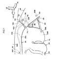
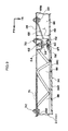
- Fig. 1 shows a magnified perspective view of principal portions, drawn around a rear seat expansion portion, an upper expansion portion and a rear expansion portion relating to principal portions of the present exemplary embodiment.
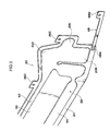
- Fig. 3 shows a plan view illustrating a state in which the airbag illustrated in Fig. 1 is deployed in a flat shape.
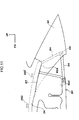
- Fig. 4 shows a magnified side elevation of principal portions in which a vicinity of the rear seat expansion portion of the airbag illustrated in Fig. 2 is magnified.
- the head protection airbag device for a vehicle 10 is constituted to include an airbag 20 and a substantially circular rod-shaped inflator 22.
- the airbag 20 is arranged in a folded state along a roof side rail 18 extending between a front pillar (pillar A) 12, a center pillar (pillar B) 14 and a quarter pillar (pillar C) 16.
- the inflator 22 is disposed at and connected to a vicinity of a length direction middle portion of the airbag 20, and serves as a gas generator that operates and discharges gas at the time of a side collision or the time of a rollover.
- the airbag 20 is formed in a substantially rectangular shape which is narrow and long in the vehicle front-rear direction.
- a periphery edge portion (outer periphery portion) of the airbag 20 serves as a non-expanding portion 24 into which the gas does not inflow.
- Plural attachment pieces 26A to 26E are formed with an appropriate spacing at an upper edge side of the non-expanding portion 24.
- Each of the attachment pieces 26A to 26E is formed in a rectangular shape.
- the attachment piece 26A at the front end side is fastened and fixed by a bolt and weld nut 27 to a front pillar inner panel of the front pillar 12, and the attachment piece 26E at the rear end side is fastened and fixed by a bolt and weld nut 30 to a quarter pillar inner panel 28 (see Fig. 1 ) of the quarter pillar 16.
- the middle portion attachment pieces 26B to 26D are fastened and fixed by bolts and weld nuts 32 to a roof side rail inner panel 31 of the roof side rail 18 (see Fig. 9 and Fig. 10 ).
- a substantially rectangular non-expanding portion 36 is formed at the vicinity of a length direction middle portion of the airbag 20.
- a front seat expansion portion 20A that expands to the side of the head area of an occupant sitting on a front seat 38, and a rear seat expansion portion 20B that expands to the side of the head area of an occupant sitting on a rear seat 40 are formed.
- the front seat expansion portion 20A and the rear seat expansion portion 20B are constituted by connecting plural cells, which are respectively formed in substantially tubular shapes, in the vehicle front-rear direction.
- the front seat expansion portion 20A and the rear seat expansion portion 20B are put into fluid communication with one another by a pair of upper and lower communication channels 42 and 44 formed between the front seat expansion portion 20A and the rear seat expansion portion 20B.
- the communication channels 42 and 44 are formed with length directions thereof in the vehicle front-rear direction.
- a gas introduction portion 20C that extends in a fin shape to the vehicle upper side is connected to a front end portion of the communication channel 42.
- a gas discharge section of the inflator 22 is connected to this gas introduction portion 20C (see Fig. 2 ), and gas inflows through the gas introduction portion 20C.
- the inflator 22 is connected to an airbag electronic control unit (ECU) (a controller) that is disposed below a console box or suchlike.
- ECU airbag electronic control unit
- the inflator 22 is electrified, operates and generates gas when a side collision state or a rollover state is detected by an unillustrated side collision detection sensor (detector) disposed at a lower portion of the center pillar 14 or the like or an unillustrated rollover detection sensor (detector) disposed in the airbag ECU or the like.
- the head protection airbag device for a vehicle 10 described above is covered by a terminal part 34A of a roof head lining 34 that serves as a ceiling member. That is, the roof head lining 34 is provided with a general portion 34B that extends in a substantially flat shape in both the vehicle front-rear direction and the vehicle width direction.
- the terminal part 34A is formed at each of the two vehicle width direction end portions of the general portion 34B.
- the terminal part 34A depends with curving and gentle inflection to the vehicle lower side from the general portion 34B.
- the airbag 20, which is folded up in a long, narrow shape, is contained along a door opening 46 at the compartment outer side of the terminal part 34A.
- an upper edge of (an upper edge of) an upper end portion 48A of a quarter pillar garnish 48 which is described below, is disposed in a state of overlapping from the compartment inner side with an end edge portion of the terminal part 34A of the roof head lining 34.
- the roof head lining 34 is connected to pillar garnishes, which are inner linings of the pillars.
- pillar garnishes which are inner linings of the pillars.
- the quarter pillar garnish 48 is described in relation to principal portions of the present exemplary embodiment.
- the quarter pillar garnish 48 which is both an inner covering and an inner lining, is provided at the compartment inner side of the quarter pillar inner panel 28 of the roof side rail 18 (see Fig. 1 ).
- the quarter pillar garnish 48 is constituted by a resin material that is harder than the roof head lining 34. Therefore, if an external force is applied, the terminal part 34A of the roof head lining 34 may bend to the compartment inner side more easily. When an external force is applied, the quarter pillar garnish 48 resiliently deforms, but is less likely to bend and more likely to break than the terminal part 34A of the roof head lining 34.
- This vehicle is a sedan-type vehicle, and the quarter pillar garnish 48 has a shape that is angled forward as viewed from the compartment inner side.
- an upper expansion portion 20D is integrally formed at the upper edge side of the rear seat expansion portion 20B of the aforementioned airbag 20 (more specifically, at the vehicle upper side relative to the single-dot chain line P joining the aforementioned attachment pieces 26A to 26E (see Fig. 3 )).
- the upper expansion portion 20D bulges to the vehicle upper side.
- Portions at the lower side relative to the single-dot chain line P are a region that may be described as the main body portion of the airbag 20 (hereinafter, this region is collectively referred to as a main body portion 50).
- the above-mentioned upper expansion portion 20D is formed in a right-angled triangle shape in a vehicle side view (with the hypotenuse oriented downward and the right-angled corner oriented upward.
- the upper expansion portion 20D is in fluid communication with the rear seat expansion portion 20B.
- a protection area S (see Fig. 4 ) of a head area side surface of an occupant sitting on the rear seat 40 is covered by the rear seat expansion portion 20B and the upper expansion portion 20D.
- the upper expansion portion 20D is disposed between the two attachment pieces 26D and 26E at the rear side.
- the upper expansion portion 20D expands and deploys at the compartment outer side of the terminal part 34A of the roof head lining 34 (see Fig. 1 ).
- a rear expansion portion 20E is integrally formed at a rear end portion of the above-mentioned rear seat expansion portion 20B of the airbag 20.
- the rear expansion portion 20E protrudes toward the vehicle rear side.
- the rear expansion portion 20E is disposed at a rear end upper portion of the rear seat expansion portion 20B, and is in fluid communication with the rear seat expansion portion 20B.
- the aforementioned rear end side attachment piece 26E is set at the non-expanding portion 24 that is formed at an outer periphery portion of the rear expansion portion 20E.
- the rear expansion portion 20E is disposed at the compartment outer side of the quarter pillar garnish 48 (in other words, is disposed such that, viewed from the compartment inner side, the rear expansion portion 20E is superposed (overlaps) with the upper end portion 48A of the quarter pillar garnish 48).
- the rear end side attachment piece 26E is fixed to the quarter pillar inner panel 28 of the quarter pillar 16 by the bolt and weld nut 30.
- the rear expansion portion 20E expands between the quarter pillar inner panel 28 and the quarter pillar garnish 48.
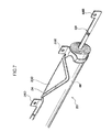
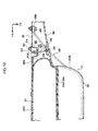
- a strap 52 that serves as a coupler. More specifically, as illustrated in Fig. 9 and Fig. 10 , a pedestal portion 54 protruding to the compartment inner side is integrally formed at the quarter pillar inner panel 28. Correspondingly, a pedestal portion 56 that protrudes to the compartment outer side is integrally formed at a position of a compartment outer side face of the quarter pillar garnish 48 that opposes the pedestal portion 54. Insertion holes 58 and 60 are formed at central portions of the pedestal portions 54 and 56.
- One end portion of the strap 52 which is formed in a cord shape of a resin material, is anchored in the insertion hole 58 at the pedestal portion 54.
- a resin clip 62 is integrally formed at the one end portion of the strap 52, and this resin clip 62 is inserted into and anchored at the insertion hole 58.
- An anchoring portion 64 for preventing disengagement is integrally formed at the other end portion of the strap 52. This anchoring portion 64 is inserted into and anchored in the insertion hole 60 at the pedestal portion 56, and thus the other end portion of the strap 52 is prevented from disengaging from the quarter pillar garnish 48.
- a length of the strap 52 is specified to be longer by a predetermined length than a gap dimension L of a gap 66 (see Fig. 9 ) that is formed between the compartment outer side face of the quarter pillar garnish 48 and the compartment inner side face of the quarter pillar inner panel 28, in the assembled state.
- a separation distance when the rear expansion portion 20E expands and an unillustrated resin clip for stopping which is formed at the quarter pillar garnish 48 detaches from the quarter pillar inner panel 28 (a movement distance thereof to the compartment inner side) is regulated.
- a rear side strap 68 that serves as a tension imparting member is disposed at a lower edge side rear end portion of the aforementioned non-expanding portion 24 of the airbag 20.
- the rear side strap 68 is structured as a belt member constituted of the same material as the airbag 20, and a front end portion 68A thereof is fixed by sewing or the like to the lower edge side rear end portion of the non-expanding portion 24.
- a rear end portion 68B of the rear side strap 68 is attached by a bolt and weld nut 69 to the quarter pillar inner panel 28 of the quarter pillar 16.
- a front side strap 70 with a similar constitution to the rear side strap 68 is provided at the front side of the airbag 20 at the front side of the airbag 20.
- a front end portion 70A of the front side strap 70 is fixed by a bolt and weld nut 71 to a pillar inner panel (not illustrated) of the front pillar 12.
- a rear end portion 70B of the front side strap 70 is fixed by sewing or the like to a lower edge side front end portion of the non-expanding portion 24 of the airbag 20.
- a border portion 72 between the roof head lining 34 and the quarter pillar garnish 48 is specified such that, in the state in which the airbag 20 has expanded and deployed, a deployment area of the upper expansion portion 20D (the shaded portion Q in Fig. 4 ) falls within a range where the roof head lining 34 is arranged. That is, a quarter pillar side protrusion portion 34C of the roof head lining 34 is protruded as far as a position such that the deployment area Q of the upper expansion portion 20D does not impinge on the upper end portion 48A of the quarter pillar garnish 48.
- the airbag 20 is put into a flat deployment condition as illustrated in Fig. 3 to Fig. 5 .
- the main body portion 50 of the airbag 20 is folded up by roll-folding.
- the upper expansion portion 20D is folded by bellows-folding.
- the folded upper expansion portion 20D is placed on the upper face of the main body portion 50 that has already been folded into a roll.
- the gas inflows into the airbag 20 through the gas introduction portion 20C.
- the inflowing gas flows through the communication channels 42 and 44 into the front seat expansion portion 20A and the rear seat expansion portion 20B, and also flows into the upper expansion portion 20D and the rear expansion portion 20E.
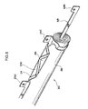
- the rear expansion portion 20E expands and, subj ect to a reaction force at the quarter pillar inner panel 28, pushes the quarter pillar garnish 48 to the compartment inner side. Accordingly, the unillustrated resin clip detaches from the quarter pillar inner panel 28, and hence the quarter pillar garnish 48 separates (moves) to the compartment inner side.
- the separation distance is regulated to a predetermined distance (for example, 40 mm).
- the gap 66 between the quarter pillar garnish 48 and the quarter pillar inner panel 28 is widened, and it is easier for the rear side strap 68 to pass therethrough.
- the front seat expansion portion 20A and rear seat expansion portion 20B of the airbag 20 are expanded and deployed in the form of a curtain below the roof side rail, while pushing the terminal part 34A of the roof head lining 34 open to the compartment inner side.
- the upper expansion portion 20D is expanded and deployed to the compartment outer side of the terminal part 34A of the roof head lining 34, more promptly than the rear seat expansion portion 20B.
- the front seat expansion portion 20A is interposed between the head area side surface of an occupant sitting on the front seat 38 and the door glass of a front side door 74, and the head area side surface of this occupant is protected by the front seat expansion portion 20A.
- the rear seat expansion portion 20B is interposed between the head area side surface of an occupant sitting on the rear seat 40 and the door glass of a rear side door 76, and the head area side surface of this occupant is protected by the rear seat expansion portion 20B and, integrally therewith, the upper expansion portion 20D that covers the protection area S of the head area side surface of this occupant.
- a tension line T is formed between the front end portion 70A of the front side strap 70 that is the front end fixing point and the rear end portion 68B of the rear side strap 68 that is the rear end fixing point.
- This tension line T is formed at a position that is lowered to the vehicle lower side relative to a tension line if the rear end fixing point were at the upper edge side of the rear seat expansion portion 20B (at the position of the attachment piece 26D of the present exemplary embodiment) as in the related art. Therefore, in comparison with a related art structure, an effect of preventing exposure of the occupant outside the vehicle at the time of a rollover is improved.
- the border portion 72 between the roof head lining 34 and the quarter pillar garnish 48 is specified such that the deployment area Q of the upper expansion portion 20D falls within the area of arrangement of the roof head lining 34. Consequently, when the rear seat expansion portion 20B expands and deploys toward the vehicle lower side, the rear seat expansion portion 20B is prevented or inhibited from hooking on the upper end portion 48A of the quarter pillar garnish 48.
- the rear side strap 68 is provided but, because the quarter pillar garnish 48 is moved away (lifted) from the quarter pillar inner panel 28 by the rear expansion portion 20E and the separation distance thereof is regulated by the strap 52, the rear side strap 68 is smoothly pulled out from the containment position to positions along the belt line by passing through the enlarged gap 66 between the quarter pillar garnish 48 and the quarter pillar inner panel 28, without hooking on the quarter pillar garnish 48.
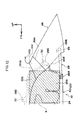
- FIG. 11 A deployed state of a related art airbag 80 is illustrated in Fig. 11 .
- the above-mentioned protection area S is covered by a roll-folded rear seat expansion portion 80A. Therefore, the rear seat expansion portion 80A is disposed at the upper edge side of the protection area S.
- the rear seat expansion portion 80A is expanded and deployed to the compartment inner side through a border portion 83 between the roof head lining 34 and a quarter pillar garnish 82. Therefore, if a rear side strap 84 were set, when the rear side strap 84 descended from a containment position (the position shown by two-dot chain lines in Fig.
- the rear side strap 84 would hook on an upper end portion 82A of the quarter pillar garnish 82.
- the protection area S overlaps with the upper end portion 82A of the quarter pillar garnish 82. Therefore, the likelihood of the rear side strap 84 hooking on the upper end portion 82A of the quarter pillar garnish 82 is higher.
- the rear end side attachment piece 26E is moved to sideward of the rear seat expansion portion 20B, the upper expansion portion 20D is set at the upper edge side of the rear seat expansion portion 20B, the border portion 72 between the roof head lining 34 and the quarter pillar garnish 48 is specified so as not to impinge on the protection area S, and the rear expansion portion 20E is added and moves the quarter pillar garnish 48 away from the quarter pillar inner panel 28. Therefore, the above-described concern does not arise.
- the rear side strap 68 may be prevented or inhibited from hooking on the upper end portion 48A of the quarter pillar garnish 48 and impeding deployment of the airbag 20.
- the rear end side attachment piece 20E (rear end side fixing portion) of the airbag 20 is set at a position along the door opening 46. Therefore, when the rear seat expansion portion 20B expands and deploys, the rear seat expansion portion 20B may be supported from a position close to the rear seat expansion portion 20B. As a result, flapping of the rear seat expansion portion 20B at the time of expansion and deployment of the rear seat expansion portion 20B may be effectively suppressed.
- the rear expansion portion 20E is set at the upper rear end side of the rear seat expansion portion 20B as described above so as to separate the quarter pillar garnish 48 from the quarter pillar inner panel 28.
- the rear side strap 68 may quickly form the tension line T at the lower side of the rear expansion portion 20E.
- the attachment piece 26E is set at a rear end upper portion of the rear expansion portion 20E.
- the rear expansion portion 20E is expanded subject to a portion of a reaction force at the attachment piece 26E. Therefore, the quarter pillar garnish 48 may be quickly pushed to the compartment inner side.
- the rear side strap 68 may be quickly moved at the time of the expansion and deployment of the rear seat expansion portion 20B.
- the quarter pillar garnish 48 is coupled to the quarter pillar inner panel 28 by the strap 52 and the movement distance when the quarter pillar garnish 48 detaches from the quarter pillar inner panel 28 and moves to the compartment inner side is regulated.
- the quarter pillar garnish 48 may be prevented or inhibited from deforming excessively and breaking or scattering.
- the thickness of the rear expansion portion 20E is specified to be not more than half the thickness of the rear seat expansion portion 20B.
- deformation of the quarter pillar garnish 48 may be mostly suppressed. Therefore, breakage and scattering of the quarter pillar garnish 48 may be assuredly prevented.
- the lower side with reference to the upper edge of the airbag 20 is roll-folded, and the upper expansion portion 20D that is at the upper side with reference to the upper edge of the airbag 20 is folded up by bellows-folding, and a bellows-folded portion 86 is placed on a roll-folded portion 88.
- the upper expansion portion 20D expands and deploys prior to the front seat expansion portion 20A and the rear seat expansion portion 20B. Therefore, the protection area S of the head area side surface of an occupant sitting on the rear seat 40 may be quickly covered by the rear seat expansion portion 20B.
- the inflator 22 is disposed at a substantial middle portion of the airbag 20 in the length direction thereof.
- gas is supplied in parallel to both the front seat expansion portion 20A and the rear seat expansion portion 20B. Therefore, according to the present exemplary embodiment, the front seat expansion portion 20A and the rear seat expansion portion 20B may be expanded and deployed quickly.
- FIG. 12 a second exemplary embodiment of the head protection airbag device for a vehicle relating to the present invention is described using Fig. 12 .
- Structural portions that are the same as in the first exemplary embodiment described above are assigned the same reference numerals and are not described.
- the quarter pillar side protrusion portion 34C of the roof head lining 34 of the above first exemplary embodiment is constituted by two components. That is, in this second exemplary embodiment, a protrusion portion 100A of a roof head lining 100 is shortened.
- This supplementary ceiling member 102 is constituted of the same material as the roof head lining 100.
- the quarter pillar garnish 48 is the same as in the first exemplary embodiment. Therefore, the position of the border portion 72 is unchanged.
- the supplementary ceiling member 102 may be disposed at the deployment area Q of the upper expansion portion 20D.
- a structure substantially the same as in the first exemplary embodiment described above may be formed.
- molding characteristics and productivity of the roof head lining 100 may be excellently maintained.
- a portion of the protrusion portion 100A of the roof head lining 100 is supplemented by the supplementary ceiling member 102, but this is not a limitation.
- a portion of the quarter pillar garnish 48 may be divided off to serve as the supplementary ceiling member 102.
- the attachment piece 26E corresponds to the rear end side fixing portion of claim 1.
- the attachment piece 26E is an aspect of being "set at a non-expanding portion 24, which is provided at the vehicle outer side of the rear seat expansion portion".
- the tension line of the airbag 20 is a line joining the bolt fastening point of the attachment piece 26E with the bolt fastening point of the front end portion 70A of the front side strap 70. In comparison with the related art structure mentioned above, this tension line is lowered to the vehicle lower side. Therefore, the effect of impeding exposure of an occupant outside the vehicle can be said to be significant.
- rear end side fixing portions may be set at both the vehicle rear side of the rear seat expansion portion 20B and the vehicle rear side of the upper expansion portion 20D.
- tension lines are respectively formed at a line joining the fixing point set at the vehicle rear side of the rear seat expansion portion 20B with the bolt fastening point of the front end portion 70A of the front side strap 70, and a line joining the fixing point set at the vehicle rear side of the upper expansion portion 20D with the bolt fastening point of the front end portion 70A of the front side strap 70.
- the tension line formed further to the vehicle lower side serves as the tension line of the airbag.
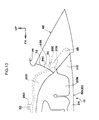
- a device in which an enlarged non-expanding portion 110 as illustrated in Fig. 13 is specified in place of the rear side strap 68 used in the first exemplary embodiment is to be included in the scope of the invention of claim 1.
- the triangular non-expanding portion 110 which serves as the tension imparting member, is integrally formed at the lower rear end side of the rear seat expansion portion 20B.
- the non-expanding portion 110 is formed over a range that contains that of the rear side strap 68.
- a rear end portion of this non-expanding portion 110 is fastened and fixed to the quarter pillar inner panel 28 by the bolt and weld nut 69. Therefore, in this structure, the tension line is formed at exactly the same position as in the first exemplary embodiment, and the same operation and effects are provided.
- using the rear side strap 68 is advantageous for productivity when making the airbag 20.
- the upper expansion portion 20D is folded up by bellows-folding, but this is not limiting.
- the upper expansion portion 20D may be folded up by roll-folding.
- the strap 52 is used as the coupler that couples the quarter pillar garnish 48 with the quarter pillar inner panel 28, but this is not limiting and other structures may be used.
- foldable ring-form members may be provided at the quarter pillar garnish 48 and the quarter pillar inner panel 28.
- the inflator 22 is disposed at the vehicle front-rear direction substantially middle position of the upper edge side of the airbag 20, but this is not limiting.
- the inflator 22 may be disposed at the front end side of the airbag 20 and may be disposed at the rear end side of the airbag 20.
Landscapes
- Engineering & Computer Science (AREA)
- Mechanical Engineering (AREA)
- Air Bags (AREA)
- Body Structure For Vehicles (AREA)
Applications Claiming Priority (1)
| Application Number | Priority Date | Filing Date | Title |
|---|---|---|---|
| PCT/JP2009/051781 WO2010089847A1 (ja) | 2009-02-03 | 2009-02-03 | 乗用車用頭部保護エアバッグ装置 |
Publications (3)
| Publication Number | Publication Date |
|---|---|
| EP2394868A1 true EP2394868A1 (de) | 2011-12-14 |
| EP2394868A4 EP2394868A4 (de) | 2012-07-04 |
| EP2394868B1 EP2394868B1 (de) | 2014-08-13 |
Family
ID=42541771
Family Applications (1)
| Application Number | Title | Priority Date | Filing Date |
|---|---|---|---|
| EP09839625.2A Not-in-force EP2394868B1 (de) | 2009-02-03 | 2009-02-03 | Airbagvorrichtung zum schützen des kopfes in einem auto |
Country Status (6)
| Country | Link |
|---|---|
| US (1) | US8505967B2 (de) |
| EP (1) | EP2394868B1 (de) |
| JP (1) | JP5267579B2 (de) |
| CN (1) | CN102300750B (de) |
| MX (1) | MX2011008189A (de) |
| WO (1) | WO2010089847A1 (de) |
Families Citing this family (16)
| Publication number | Priority date | Publication date | Assignee | Title |
|---|---|---|---|---|
| US8876155B2 (en) * | 2011-04-20 | 2014-11-04 | Autoliv Development Ab | Curtain airbag device for vehicle |
| JP5846643B2 (ja) * | 2012-08-31 | 2016-01-20 | トヨタ車体株式会社 | カーテンシールドエアバッグの取付構造 |
| WO2014132810A1 (ja) | 2013-02-28 | 2014-09-04 | オートリブ ディベロップメント エービー | カーテンエアバッグ |
| JP6294952B2 (ja) | 2013-03-15 | 2018-03-14 | オートリブ エーエスピー,インコーポレイティド | Icのための二重折りにして巻かれたクッション |
| US9266494B2 (en) * | 2013-03-15 | 2016-02-23 | Autoliv Asp, Inc. | Fold over design for small overlap |
| JP6186216B2 (ja) * | 2013-09-09 | 2017-08-23 | セーレン株式会社 | エアバッグ用ベルト |
| JP6299426B2 (ja) * | 2013-09-26 | 2018-03-28 | 豊田合成株式会社 | 頭部保護エアバッグ装置 |
| US9156427B2 (en) * | 2014-01-08 | 2015-10-13 | Autoliv Asp, Inc. | Cost-effective use of one-piece woven fabric for curtain airbags |
| JP6386361B2 (ja) * | 2014-12-12 | 2018-09-05 | トヨタ自動車株式会社 | 車両用カーテンエアバッグを収納したルーフヘッドライニング構造 |
| JP6222156B2 (ja) * | 2015-04-07 | 2017-11-01 | マツダ株式会社 | 車両の乗員保護装置 |
| JP6460070B2 (ja) | 2016-09-14 | 2019-01-30 | トヨタ自動車株式会社 | 車両用カーテンエアバッグ装置 |
| JP6540647B2 (ja) | 2016-10-07 | 2019-07-10 | トヨタ自動車株式会社 | 車両用カーテンエアバッグ装置 |
| JP6831271B2 (ja) * | 2017-03-08 | 2021-02-17 | Joyson Safety Systems Japan株式会社 | カーテンエアバッグ及びカーテンエアバッグ装置 |
| JP6772987B2 (ja) | 2017-08-09 | 2020-10-21 | トヨタ自動車株式会社 | 車両用カーテンエアバッグ装置 |
| DE102018216961B4 (de) * | 2018-10-02 | 2024-12-19 | Volkswagen Aktiengesellschaft | Insassenschutzvorrichtung für ein Kraftfahrzeug sowie Kraftfahrzeug |
| US11912229B2 (en) * | 2021-03-30 | 2024-02-27 | Honda Motor Co., Ltd. | Lid for airbag tether deployment in vehicles |
Family Cites Families (24)
| Publication number | Priority date | Publication date | Assignee | Title |
|---|---|---|---|---|
| JP3560127B2 (ja) | 1998-06-19 | 2004-09-02 | トヨタ自動車株式会社 | 前後席用頭部保護エアバッグ装置 |
| US6371512B1 (en) | 1998-08-03 | 2002-04-16 | Toyota Jidosha Kabushiki Kaisha | Airbag apparatus for head-protecting |
| JP3107072B2 (ja) * | 1998-12-01 | 2000-11-06 | トヨタ自動車株式会社 | 頭部保護エアバッグ装置 |
| JP3499465B2 (ja) | 1999-07-06 | 2004-02-23 | トヨタ自動車株式会社 | 頭部保護エアバッグ装置搭載車両におけるピラーガーニッシュ取付構造 |
| US6375214B1 (en) | 1999-07-12 | 2002-04-23 | Mazda Motor Corporation | Occupant protection device of vehicle |
| JP3812228B2 (ja) | 1999-07-12 | 2006-08-23 | マツダ株式会社 | 車両の乗員保護装置 |
| JP3520507B2 (ja) | 1999-09-14 | 2004-04-19 | 豊田合成株式会社 | 頭部保護エアバッグ |
| JP3506066B2 (ja) | 1999-09-24 | 2004-03-15 | トヨタ自動車株式会社 | 頭部保護エアバッグ装置 |
| JP2001106014A (ja) | 1999-10-14 | 2001-04-17 | Toyota Motor Corp | 頭部保護エアバッグ装置 |
| JP2002187497A (ja) | 2000-12-22 | 2002-07-02 | Kasai Kogyo Co Ltd | 自動車用内装部品構造 |
| US6481743B1 (en) * | 2001-06-01 | 2002-11-19 | Delphi Technologies, Inc. | Side curtain air bag |
| JP3633537B2 (ja) | 2001-09-27 | 2005-03-30 | トヨタ自動車株式会社 | 車両用内装部品の取付構造 |
| JP4063095B2 (ja) | 2002-03-08 | 2008-03-19 | 豊田合成株式会社 | 頭部保護エアバッグ装置 |
| US6830262B2 (en) * | 2002-07-11 | 2004-12-14 | Autoliv Asp, Inc. | Inflatable airbag deployment guide |
| US7077425B2 (en) | 2002-09-19 | 2006-07-18 | Toyoda Gosei Co., Ltd. | Head protecting airbag device |
| JP2004114895A (ja) | 2002-09-27 | 2004-04-15 | Toyoda Gosei Co Ltd | 頭部保護エアバッグ装置 |
| JP2004148853A (ja) | 2002-10-28 | 2004-05-27 | Toyota Motor Corp | 頭部保護エアバッグ装置 |
| JP3759496B2 (ja) * | 2002-12-20 | 2006-03-22 | 本田技研工業株式会社 | 乗員拘束装置 |
| DE102005002085B4 (de) | 2004-03-17 | 2013-09-05 | TAKATA Aktiengesellschaft | Seitenairbageinrichtung |
| JP4622412B2 (ja) * | 2004-09-21 | 2011-02-02 | タカタ株式会社 | カーテンエアバッグ装置及び車両 |
| JP4887696B2 (ja) | 2005-09-06 | 2012-02-29 | 豊田合成株式会社 | 頭部保護エアバッグ装置 |
| JP4619914B2 (ja) | 2005-09-30 | 2011-01-26 | 株式会社イノアックコーポレーション | 車両内装部材 |
| DE102006061968A1 (de) * | 2006-12-21 | 2008-07-03 | Autoliv Development Ab | Vorhang-Gassack |
| US7823922B2 (en) * | 2008-07-16 | 2010-11-02 | Autoliv Asp, Inc. | Tether systems for inflatable cushions |
-
2009
- 2009-02-03 US US13/147,379 patent/US8505967B2/en not_active Expired - Fee Related
- 2009-02-03 MX MX2011008189A patent/MX2011008189A/es active IP Right Grant
- 2009-02-03 EP EP09839625.2A patent/EP2394868B1/de not_active Not-in-force
- 2009-02-03 CN CN200980156046.XA patent/CN102300750B/zh not_active Expired - Fee Related
- 2009-02-03 WO PCT/JP2009/051781 patent/WO2010089847A1/ja not_active Ceased
- 2009-02-03 JP JP2010549290A patent/JP5267579B2/ja not_active Expired - Fee Related
Also Published As
| Publication number | Publication date |
|---|---|
| MX2011008189A (es) | 2011-10-06 |
| JP5267579B2 (ja) | 2013-08-21 |
| WO2010089847A1 (ja) | 2010-08-12 |
| EP2394868A4 (de) | 2012-07-04 |
| CN102300750A (zh) | 2011-12-28 |
| US8505967B2 (en) | 2013-08-13 |
| EP2394868B1 (de) | 2014-08-13 |
| US20110285117A1 (en) | 2011-11-24 |
| CN102300750B (zh) | 2014-10-15 |
| JPWO2010089847A1 (ja) | 2012-08-09 |
Similar Documents
| Publication | Publication Date | Title |
|---|---|---|
| EP2394868B1 (de) | Airbagvorrichtung zum schützen des kopfes in einem auto | |
| CN102089189B (zh) | 安全气囊装置 | |
| JP6386361B2 (ja) | 車両用カーテンエアバッグを収納したルーフヘッドライニング構造 | |
| US9027954B2 (en) | Airbag device | |
| JP5380493B2 (ja) | サイドカーテンエアバッグ | |
| US7673897B2 (en) | Head-protecting airbag apparatus | |
| CN102869549B (zh) | 车用帘式气囊装置 | |
| JPWO2012147490A1 (ja) | カーテンエアバッグ装置 | |
| JP2010052457A (ja) | 車両用ニーエアバッグ装置 | |
| JP6895345B2 (ja) | エアバッグ | |
| JP3353722B2 (ja) | 頭部保護エアバッグ袋体 | |
| CN102463960B (zh) | 帘式安全气囊装置 | |
| US20060202451A1 (en) | Curtain airbag device | |
| JP2010083240A (ja) | エアバッグ及びエアバッグ装置 | |
| JP5151867B2 (ja) | カーテンエアバッグを備えた車両の内装構造 | |
| JP5034552B2 (ja) | カーテンエアバッグ装置を備えた車両の後部構造 | |
| WO2006013955A1 (ja) | カーテンエアバッグ装置 | |
| KR102366814B1 (ko) | 커튼 에어백 및 커튼 에어백의 전개 방법 | |
| JP5092448B2 (ja) | カーテンエアバッグ装置を備えた車両の後部構造 | |
| WO2012124549A1 (ja) | エアバッグ装置 | |
| JP2013249025A (ja) | カーテンエアバッグ | |
| JP2011020492A (ja) | カーテンエアバッグ装置の取付構造 | |
| JP2007261514A (ja) | エアバッグ装置 | |
| KR20170124856A (ko) | 커튼 에어백의 유지 부재 및 커튼 에어백 장치 | |
| JP2007269058A (ja) | カーテンエアバッグ装置を備えた車両の後部構造 |
Legal Events
| Date | Code | Title | Description |
|---|---|---|---|
| PUAI | Public reference made under article 153(3) epc to a published international application that has entered the european phase |
Free format text: ORIGINAL CODE: 0009012 |
|
| 17P | Request for examination filed |
Effective date: 20110824 |
|
| AK | Designated contracting states |
Kind code of ref document: A1 Designated state(s): AT BE BG CH CY CZ DE DK EE ES FI FR GB GR HR HU IE IS IT LI LT LU LV MC MK MT NL NO PL PT RO SE SI SK TR |
|
| DAX | Request for extension of the european patent (deleted) | ||
| A4 | Supplementary search report drawn up and despatched |
Effective date: 20120601 |
|
| RIC1 | Information provided on ipc code assigned before grant |
Ipc: B60R 21/20 20110101AFI20120525BHEP |
|
| RAP1 | Party data changed (applicant data changed or rights of an application transferred) |
Owner name: TOYOTA JIDOSHA KABUSHIKI KAISHA |
|
| 17Q | First examination report despatched |
Effective date: 20130412 |
|
| GRAP | Despatch of communication of intention to grant a patent |
Free format text: ORIGINAL CODE: EPIDOSNIGR1 |
|
| INTG | Intention to grant announced |
Effective date: 20140225 |
|
| GRAS | Grant fee paid |
Free format text: ORIGINAL CODE: EPIDOSNIGR3 |
|
| GRAA | (expected) grant |
Free format text: ORIGINAL CODE: 0009210 |
|
| AK | Designated contracting states |
Kind code of ref document: B1 Designated state(s): AT BE BG CH CY CZ DE DK EE ES FI FR GB GR HR HU IE IS IT LI LT LU LV MC MK MT NL NO PL PT RO SE SI SK TR |
|
| REG | Reference to a national code |
Ref country code: GB Ref legal event code: FG4D |
|
| REG | Reference to a national code |
Ref country code: AT Ref legal event code: REF Ref document number: 682012 Country of ref document: AT Kind code of ref document: T Effective date: 20140815 Ref country code: CH Ref legal event code: EP |
|
| REG | Reference to a national code |
Ref country code: IE Ref legal event code: FG4D |
|
| REG | Reference to a national code |
Ref country code: DE Ref legal event code: R096 Ref document number: 602009026053 Country of ref document: DE Effective date: 20140925 |
|
| REG | Reference to a national code |
Ref country code: DE Ref legal event code: R084 Ref document number: 602009026053 Country of ref document: DE |
|
| REG | Reference to a national code |
Ref country code: DE Ref legal event code: R084 Ref document number: 602009026053 Country of ref document: DE Effective date: 20141117 |
|
| REG | Reference to a national code |
Ref country code: NL Ref legal event code: VDEP Effective date: 20140813 |
|
| REG | Reference to a national code |
Ref country code: AT Ref legal event code: MK05 Ref document number: 682012 Country of ref document: AT Kind code of ref document: T Effective date: 20140813 |
|
| REG | Reference to a national code |
Ref country code: LT Ref legal event code: MG4D |
|
| PG25 | Lapsed in a contracting state [announced via postgrant information from national office to epo] |
Ref country code: FI Free format text: LAPSE BECAUSE OF FAILURE TO SUBMIT A TRANSLATION OF THE DESCRIPTION OR TO PAY THE FEE WITHIN THE PRESCRIBED TIME-LIMIT Effective date: 20140813 Ref country code: PT Free format text: LAPSE BECAUSE OF FAILURE TO SUBMIT A TRANSLATION OF THE DESCRIPTION OR TO PAY THE FEE WITHIN THE PRESCRIBED TIME-LIMIT Effective date: 20141215 Ref country code: NO Free format text: LAPSE BECAUSE OF FAILURE TO SUBMIT A TRANSLATION OF THE DESCRIPTION OR TO PAY THE FEE WITHIN THE PRESCRIBED TIME-LIMIT Effective date: 20141113 Ref country code: LT Free format text: LAPSE BECAUSE OF FAILURE TO SUBMIT A TRANSLATION OF THE DESCRIPTION OR TO PAY THE FEE WITHIN THE PRESCRIBED TIME-LIMIT Effective date: 20140813 Ref country code: GR Free format text: LAPSE BECAUSE OF FAILURE TO SUBMIT A TRANSLATION OF THE DESCRIPTION OR TO PAY THE FEE WITHIN THE PRESCRIBED TIME-LIMIT Effective date: 20141114 Ref country code: BG Free format text: LAPSE BECAUSE OF FAILURE TO SUBMIT A TRANSLATION OF THE DESCRIPTION OR TO PAY THE FEE WITHIN THE PRESCRIBED TIME-LIMIT Effective date: 20141113 Ref country code: ES Free format text: LAPSE BECAUSE OF FAILURE TO SUBMIT A TRANSLATION OF THE DESCRIPTION OR TO PAY THE FEE WITHIN THE PRESCRIBED TIME-LIMIT Effective date: 20140813 Ref country code: SE Free format text: LAPSE BECAUSE OF FAILURE TO SUBMIT A TRANSLATION OF THE DESCRIPTION OR TO PAY THE FEE WITHIN THE PRESCRIBED TIME-LIMIT Effective date: 20140813 |
|
| PG25 | Lapsed in a contracting state [announced via postgrant information from national office to epo] |
Ref country code: HR Free format text: LAPSE BECAUSE OF FAILURE TO SUBMIT A TRANSLATION OF THE DESCRIPTION OR TO PAY THE FEE WITHIN THE PRESCRIBED TIME-LIMIT Effective date: 20140813 Ref country code: AT Free format text: LAPSE BECAUSE OF FAILURE TO SUBMIT A TRANSLATION OF THE DESCRIPTION OR TO PAY THE FEE WITHIN THE PRESCRIBED TIME-LIMIT Effective date: 20140813 Ref country code: CY Free format text: LAPSE BECAUSE OF FAILURE TO SUBMIT A TRANSLATION OF THE DESCRIPTION OR TO PAY THE FEE WITHIN THE PRESCRIBED TIME-LIMIT Effective date: 20140813 Ref country code: IS Free format text: LAPSE BECAUSE OF FAILURE TO SUBMIT A TRANSLATION OF THE DESCRIPTION OR TO PAY THE FEE WITHIN THE PRESCRIBED TIME-LIMIT Effective date: 20141213 Ref country code: LV Free format text: LAPSE BECAUSE OF FAILURE TO SUBMIT A TRANSLATION OF THE DESCRIPTION OR TO PAY THE FEE WITHIN THE PRESCRIBED TIME-LIMIT Effective date: 20140813 |
|
| PG25 | Lapsed in a contracting state [announced via postgrant information from national office to epo] |
Ref country code: NL Free format text: LAPSE BECAUSE OF FAILURE TO SUBMIT A TRANSLATION OF THE DESCRIPTION OR TO PAY THE FEE WITHIN THE PRESCRIBED TIME-LIMIT Effective date: 20140813 |
|
| PG25 | Lapsed in a contracting state [announced via postgrant information from national office to epo] |
Ref country code: IT Free format text: LAPSE BECAUSE OF FAILURE TO SUBMIT A TRANSLATION OF THE DESCRIPTION OR TO PAY THE FEE WITHIN THE PRESCRIBED TIME-LIMIT Effective date: 20140813 Ref country code: CZ Free format text: LAPSE BECAUSE OF FAILURE TO SUBMIT A TRANSLATION OF THE DESCRIPTION OR TO PAY THE FEE WITHIN THE PRESCRIBED TIME-LIMIT Effective date: 20140813 Ref country code: EE Free format text: LAPSE BECAUSE OF FAILURE TO SUBMIT A TRANSLATION OF THE DESCRIPTION OR TO PAY THE FEE WITHIN THE PRESCRIBED TIME-LIMIT Effective date: 20140813 Ref country code: SK Free format text: LAPSE BECAUSE OF FAILURE TO SUBMIT A TRANSLATION OF THE DESCRIPTION OR TO PAY THE FEE WITHIN THE PRESCRIBED TIME-LIMIT Effective date: 20140813 Ref country code: DK Free format text: LAPSE BECAUSE OF FAILURE TO SUBMIT A TRANSLATION OF THE DESCRIPTION OR TO PAY THE FEE WITHIN THE PRESCRIBED TIME-LIMIT Effective date: 20140813 Ref country code: RO Free format text: LAPSE BECAUSE OF FAILURE TO SUBMIT A TRANSLATION OF THE DESCRIPTION OR TO PAY THE FEE WITHIN THE PRESCRIBED TIME-LIMIT Effective date: 20140813 |
|
| PGFP | Annual fee paid to national office [announced via postgrant information from national office to epo] |
Ref country code: DE Payment date: 20150127 Year of fee payment: 7 |
|
| REG | Reference to a national code |
Ref country code: DE Ref legal event code: R097 Ref document number: 602009026053 Country of ref document: DE |
|
| PG25 | Lapsed in a contracting state [announced via postgrant information from national office to epo] |
Ref country code: PL Free format text: LAPSE BECAUSE OF FAILURE TO SUBMIT A TRANSLATION OF THE DESCRIPTION OR TO PAY THE FEE WITHIN THE PRESCRIBED TIME-LIMIT Effective date: 20140813 |
|
| PLBE | No opposition filed within time limit |
Free format text: ORIGINAL CODE: 0009261 |
|
| STAA | Information on the status of an ep patent application or granted ep patent |
Free format text: STATUS: NO OPPOSITION FILED WITHIN TIME LIMIT |
|
| PG25 | Lapsed in a contracting state [announced via postgrant information from national office to epo] |
Ref country code: BE Free format text: LAPSE BECAUSE OF NON-PAYMENT OF DUE FEES Effective date: 20150228 |
|
| 26N | No opposition filed |
Effective date: 20150515 |
|
| PG25 | Lapsed in a contracting state [announced via postgrant information from national office to epo] |
Ref country code: LU Free format text: LAPSE BECAUSE OF FAILURE TO SUBMIT A TRANSLATION OF THE DESCRIPTION OR TO PAY THE FEE WITHIN THE PRESCRIBED TIME-LIMIT Effective date: 20150203 |
|
| REG | Reference to a national code |
Ref country code: CH Ref legal event code: PL |
|
| GBPC | Gb: european patent ceased through non-payment of renewal fee |
Effective date: 20150203 |
|
| PG25 | Lapsed in a contracting state [announced via postgrant information from national office to epo] |
Ref country code: LI Free format text: LAPSE BECAUSE OF NON-PAYMENT OF DUE FEES Effective date: 20150228 Ref country code: CH Free format text: LAPSE BECAUSE OF NON-PAYMENT OF DUE FEES Effective date: 20150228 Ref country code: MC Free format text: LAPSE BECAUSE OF FAILURE TO SUBMIT A TRANSLATION OF THE DESCRIPTION OR TO PAY THE FEE WITHIN THE PRESCRIBED TIME-LIMIT Effective date: 20140813 |
|
| REG | Reference to a national code |
Ref country code: IE Ref legal event code: MM4A |
|
| REG | Reference to a national code |
Ref country code: FR Ref legal event code: ST Effective date: 20151030 |
|
| PG25 | Lapsed in a contracting state [announced via postgrant information from national office to epo] |
Ref country code: SI Free format text: LAPSE BECAUSE OF FAILURE TO SUBMIT A TRANSLATION OF THE DESCRIPTION OR TO PAY THE FEE WITHIN THE PRESCRIBED TIME-LIMIT Effective date: 20140813 |
|
| PG25 | Lapsed in a contracting state [announced via postgrant information from national office to epo] |
Ref country code: GB Free format text: LAPSE BECAUSE OF NON-PAYMENT OF DUE FEES Effective date: 20150203 Ref country code: IE Free format text: LAPSE BECAUSE OF NON-PAYMENT OF DUE FEES Effective date: 20150203 |
|
| PG25 | Lapsed in a contracting state [announced via postgrant information from national office to epo] |
Ref country code: FR Free format text: LAPSE BECAUSE OF NON-PAYMENT OF DUE FEES Effective date: 20150302 |
|
| PG25 | Lapsed in a contracting state [announced via postgrant information from national office to epo] |
Ref country code: BE Free format text: LAPSE BECAUSE OF FAILURE TO SUBMIT A TRANSLATION OF THE DESCRIPTION OR TO PAY THE FEE WITHIN THE PRESCRIBED TIME-LIMIT Effective date: 20140813 |
|
| REG | Reference to a national code |
Ref country code: DE Ref legal event code: R119 Ref document number: 602009026053 Country of ref document: DE |
|
| PG25 | Lapsed in a contracting state [announced via postgrant information from national office to epo] |
Ref country code: MT Free format text: LAPSE BECAUSE OF FAILURE TO SUBMIT A TRANSLATION OF THE DESCRIPTION OR TO PAY THE FEE WITHIN THE PRESCRIBED TIME-LIMIT Effective date: 20140813 |
|
| PG25 | Lapsed in a contracting state [announced via postgrant information from national office to epo] |
Ref country code: DE Free format text: LAPSE BECAUSE OF NON-PAYMENT OF DUE FEES Effective date: 20160901 |
|
| PG25 | Lapsed in a contracting state [announced via postgrant information from national office to epo] |
Ref country code: HU Free format text: LAPSE BECAUSE OF FAILURE TO SUBMIT A TRANSLATION OF THE DESCRIPTION OR TO PAY THE FEE WITHIN THE PRESCRIBED TIME-LIMIT; INVALID AB INITIO Effective date: 20090203 |
|
| PG25 | Lapsed in a contracting state [announced via postgrant information from national office to epo] |
Ref country code: TR Free format text: LAPSE BECAUSE OF FAILURE TO SUBMIT A TRANSLATION OF THE DESCRIPTION OR TO PAY THE FEE WITHIN THE PRESCRIBED TIME-LIMIT Effective date: 20140813 |
|
| PG25 | Lapsed in a contracting state [announced via postgrant information from national office to epo] |
Ref country code: MK Free format text: LAPSE BECAUSE OF FAILURE TO SUBMIT A TRANSLATION OF THE DESCRIPTION OR TO PAY THE FEE WITHIN THE PRESCRIBED TIME-LIMIT Effective date: 20140813 |