EP2356908B1 - Procédé et dispositif de traitement d'une pièce de carcasse de volaille abattue - Google Patents
Procédé et dispositif de traitement d'une pièce de carcasse de volaille abattue Download PDFInfo
- Publication number
- EP2356908B1 EP2356908B1 EP11160228.0A EP11160228A EP2356908B1 EP 2356908 B1 EP2356908 B1 EP 2356908B1 EP 11160228 A EP11160228 A EP 11160228A EP 2356908 B1 EP2356908 B1 EP 2356908B1
- Authority
- EP
- European Patent Office
- Prior art keywords
- harvestable
- tray
- harvestable part
- carcass
- robot
- Prior art date
- Legal status (The legal status is an assumption and is not a legal conclusion. Google has not performed a legal analysis and makes no representation as to the accuracy of the status listed.)
- Active
Links
- 238000000034 method Methods 0.000 title claims description 93
- 238000012545 processing Methods 0.000 title claims description 87
- 244000144977 poultry Species 0.000 title claims description 14
- 210000000481 breast Anatomy 0.000 claims description 42
- 238000004806 packaging method and process Methods 0.000 claims description 23
- 230000033001 locomotion Effects 0.000 claims description 21
- 210000000988 bone and bone Anatomy 0.000 claims description 15
- 238000007689 inspection Methods 0.000 claims description 10
- 238000000926 separation method Methods 0.000 claims description 10
- 238000000151 deposition Methods 0.000 claims description 9
- 229910001220 stainless steel Inorganic materials 0.000 claims description 6
- 239000010935 stainless steel Substances 0.000 claims description 6
- 239000011248 coating agent Substances 0.000 claims description 4
- 238000000576 coating method Methods 0.000 claims description 4
- 238000011179 visual inspection Methods 0.000 claims description 3
- 239000000047 product Substances 0.000 description 65
- 210000002414 leg Anatomy 0.000 description 19
- 210000000689 upper leg Anatomy 0.000 description 13
- 239000000969 carrier Substances 0.000 description 9
- 235000013372 meat Nutrition 0.000 description 7
- 210000000038 chest Anatomy 0.000 description 6
- 239000000284 extract Substances 0.000 description 5
- 238000003307 slaughter Methods 0.000 description 5
- 241001094623 Mindarus obliquus Species 0.000 description 4
- 210000003484 anatomy Anatomy 0.000 description 4
- 210000003205 muscle Anatomy 0.000 description 4
- 241001177022 Mastocarpus latissimus Species 0.000 description 3
- 241000220619 Megaselia pectoralis Species 0.000 description 3
- 241000182542 Microcerotermes serratus Species 0.000 description 3
- 210000003489 abdominal muscle Anatomy 0.000 description 3
- 238000013461 design Methods 0.000 description 3
- 210000001519 tissue Anatomy 0.000 description 3
- 241000271566 Aves Species 0.000 description 2
- 241001465754 Metazoa Species 0.000 description 2
- 241000742855 Metrichia tere Species 0.000 description 2
- 239000007795 chemical reaction product Substances 0.000 description 2
- 230000005484 gravity Effects 0.000 description 2
- 238000010191 image analysis Methods 0.000 description 2
- 235000013622 meat product Nutrition 0.000 description 2
- 238000012856 packing Methods 0.000 description 2
- 208000010392 Bone Fractures Diseases 0.000 description 1
- 208000034656 Contusions Diseases 0.000 description 1
- 241000287828 Gallus gallus Species 0.000 description 1
- 208000006670 Multiple fractures Diseases 0.000 description 1
- 210000000683 abdominal cavity Anatomy 0.000 description 1
- 238000013459 approach Methods 0.000 description 1
- 238000005452 bending Methods 0.000 description 1
- 210000001669 bursa of fabricius Anatomy 0.000 description 1
- 239000006227 byproduct Substances 0.000 description 1
- 238000010276 construction Methods 0.000 description 1
- 230000008021 deposition Effects 0.000 description 1
- 239000011888 foil Substances 0.000 description 1
- 230000003601 intercostal effect Effects 0.000 description 1
- 238000005457 optimization Methods 0.000 description 1
- 229920003023 plastic Polymers 0.000 description 1
- 238000003825 pressing Methods 0.000 description 1
- 235000020995 raw meat Nutrition 0.000 description 1
- 230000000284 resting effect Effects 0.000 description 1
- 238000007789 sealing Methods 0.000 description 1
- 210000005070 sphincter Anatomy 0.000 description 1
- 210000004341 tarsal joint Anatomy 0.000 description 1
- 238000012546 transfer Methods 0.000 description 1
- 238000009966 trimming Methods 0.000 description 1
- 238000011144 upstream manufacturing Methods 0.000 description 1
Images


Classifications
-
- A—HUMAN NECESSITIES
- A22—BUTCHERING; MEAT TREATMENT; PROCESSING POULTRY OR FISH
- A22C—PROCESSING MEAT, POULTRY, OR FISH
- A22C21/00—Processing poultry
- A22C21/0069—Deboning poultry or parts of poultry
-
- A—HUMAN NECESSITIES
- A22—BUTCHERING; MEAT TREATMENT; PROCESSING POULTRY OR FISH
- A22C—PROCESSING MEAT, POULTRY, OR FISH
- A22C21/00—Processing poultry
- A22C21/0023—Dividing poultry
-
- A—HUMAN NECESSITIES
- A22—BUTCHERING; MEAT TREATMENT; PROCESSING POULTRY OR FISH
- A22C—PROCESSING MEAT, POULTRY, OR FISH
- A22C21/00—Processing poultry
- A22C21/0023—Dividing poultry
- A22C21/003—Filleting poultry, i.e. extracting, cutting or shaping poultry fillets
-
- A—HUMAN NECESSITIES
- A22—BUTCHERING; MEAT TREATMENT; PROCESSING POULTRY OR FISH
- A22C—PROCESSING MEAT, POULTRY, OR FISH
- A22C21/00—Processing poultry
- A22C21/0053—Transferring or conveying devices for poultry
Definitions
- the invention relates to processing a carcass part of slaughtered poultry.
- the prior art has disclosed methods of processing carcass parts of slaughtered poultry into products that are attractive for the consumer such as loose inside and/or outer fillets, inside and outer fillets that are still connected to each other, half outer fillets (that is, an outer fillet from one side of the chicken) with or without the inner fillet still attached, wings with one, two or three members, back meat, quarters, drumsticks and the like.
- carcass part depending on the end product required or the group of end products required.
- carcass parts are, for example, whole products (made oven-ready), front halves without wings, front halves with the first member of one or both wings, front halves with the first and second member of one or both wings, front halves with the first, second and third member of one or both wings, front halves of one of the aforementioned types with or without skin, breast caps, breast caps with long rib, breast caps with medium rib, half breast caps, breasts, breasts with short rib, back portions without wings, back portions with one or more wings or parts of wings. Variations of these types of carcass parts are also possible as a starting point for processing.
- a carcass part to be processed is placed on a product carrier; this product carrier advances the carcass part to be processed along a path.
- Processing devices which perform a specific process on the carcass part, are disposed along this path.
- the skilled person generally refers to such processing devices as "modules".
- This patent application relates to several such modules and the processes that they perform.
- the product carriers can engage on the inside of a carcass part that is to be processed. If the carcass part still comprises one or both legs or part of one or both legs, a product carrier can alternatively engage the leg that is present, the legs that are present, the leg parts that are present or the leg part that is present.
- the control system of the slaughterhouse or processing factory where the carcass parts are being processed can, preferably, determine which processes should be carried out for each individual carcass part and which should not.
- the choice of which processes should be carried out can be determined, for example, by the specific characteristics of the individual carcass part or by the required output of specific products on a certain day.
- Not performing a certain process on a carcass part can be effected by guiding the carcass part to be processed past the module concerned in such a way that the carcass part does not come into contact with the processing components (such as blades or scrapers for example) of the associated module.
- every module can be individually switched on or off.
- the user therefore has a large degree of flexibility with regard to which processes are performed and it is also possible to introduce flexibility into the sequence in which certain processes are performed.
- the flexibility with regard to the processing sequence is present in the design, set-up and adjustment to the processing line on account of the ability to select where the modules are disposed in relation to each other along the path.
- EP 1 430 780 describes a method and a device for processing a carcass part of slaughtered poultry.
- the carcass parts to be processed comprise both bone parts and the meat that is naturally present on it.
- EP 1 430 780 describes various optimizations of the processing of such carcass parts, where the emphasis is largely on removing as much meat as possible from the bone parts.
- a disadvantage of this approach is that the meat that is removed still often requires further trimming before it can be put into a tray in a manner that is visually attractive to the consumer.
- US 6,912,434 relates to a method and device for processing a first slaughter product to form a second slaughter product, as takes place in a meat-processing factory. Measures are proposed for carrying out the processing of slaughter animals in a meat-processing factory in such a manner that the supply of slaughter animals is able as far as possible to satisfy the demand for certain quantities and certain qualities for various types of slaughter products.
- US 2002/0157919 relates to a system and method for case-packing articles utilizing an infeed conveyor and spaced apart outfeed conveyors positioned at opposite sides of the infeed conveyor and a robotic operating arm arranged for transverse operation with respect to the longitudinal movement of each of said conveyors.
- the prior art has disclosed systems for automatically packing meat products.
- the known systems comprise a vision-system with a camera; this system determines the position and orientation of each meat product that is to be packed.
- This vision-system is used to control a robot with a considerable number of degrees of freedom to pick up the product and to place the product in the packaging in the manner required.
- the known system is complicated and expensive.
- the object of the invention is to propose an improved method and an improved system for processing a carcass part of slaughtered poultry.
- a method according to independent claim 1 is proposed for processing a carcass part of slaughtered poultry, this method comprising the following steps:
- the feed device receives the harvestable part from the carcass part and deposits it in the tray that serves as the packaging.
- each harvestable part has the same orientation in relation to the feed device.
- the point at which the feed device engages the harvestable part too is always the same, obviously this is apart from the natural variations in the shape and size of the harvestable parts.
- each harvestable is placed in the packaging in the same, reproducible and inviting manner. Because the feed device engages each harvestable part in the same orientation and at the same location the feed motion that the feed device imposes on the harvestable part between the processing device and the tray can be the same in every case. Because of this complex control and complicated regulation are no longer required and the design of the feed device can be very simple.
- harvestable parts that are suitable for use in the method and the system according to the invention are, for instance, fillets (single, double), legs, quarters, skinless thighs, drumsticks, whole wings or parts of wings. Following separation from the rest of the carcass part the harvestable parts can be coated if desired.
- a product carrier can position and orient the carcass part in relation to the processing device.
- the product carrier can, for example, engage in the breast cavity or abdominal cavity of the carcass part or onto one or more leg parts.
- the harvestable part is placed in a buffer between the time that the harvestable part is separated from the rest of the carcass part and the harvestable part being fed into the tray.
- the harvestable part will be placed in the buffer in a predefined orientation so that the feed device that feeds the harvestable part into the tray is again supplied with the harvestable part in a known orientation and in a known position.
- the feed device comprises a conveyor where the harvestable parts come to lie on the conveyor in a predetermined orientation.
- This embodiment can easily be used in combination with a processing device that pulls breast fillets loose from the rib cage of a carcass part such as described in EP 1 430 780 A1 for example.
- the detached fillet is always received in the same manner from the device by the conveyor. All fillets therefore come to lie on the conveyor in the same orientation.
- the conveyor is positioned a short distance from the discharge point where the fillets leave the processing device.
- the conveyor can place the harvestable parts directly in a tray that is disposed at the end of the conveyor.
- Another possibility for getting the harvestable parts from the conveyor into a tray or small tray is a so-called drop conveyor. This is a conveyor that retracts as soon as the harvestable part is above a tray.
- the feed device comprises a robot.
- the robot can take the harvestable part from the conveyor and feed it into the tray, but, for example, it can also take the harvestable part from a buffer.
- the robot already holds the harvestable part before it is separated from the rest of the carcass part by the processing device. As soon as the harvestable part has been disconnected from the rest of the carcass part the feed device is already holding the harvestable part. As a result of this, an additional transfer is avoided and the required position and orientation of the harvestable part in relation to the feed device can be guaranteed with a high degree of accuracy.
- the robot can place the harvestable part directly into the tray, but it can also place it in a buffer. The same robot or another robot can then extract the harvestable product from the buffer again and place it in the tray.
- the robot's design can be very simple. After all, the position in which the harvestable part has to be grasped and the position in which the harvestable part has to placed in the tray are always the same. Therefore the robot does not need to make a range of different movements. The complexity of the movement that the robot needs to make therefore depends on the mutual positions of the processing device, the buffer if any and the place where the tray is disposed in order to be able to receive one or more harvestable parts. If the movement is more or less rectilinear it is possible that a single, extendable and/or pivotable arm will suffice.
- the feed device comprises a gripper to handle the harvestable part while the harvestable part is being fed into the tray. Because of its contact with the raw meat it is preferable that the gripper is made of stainless steel. In an advantageous embodiment the gripper is eccentrically mounted on a robot arm. It is preferable that the gripper is then rotatable relative to the robot arm.
- This advantageous embodiment is particularly suitable for a variation of the method where the feed device grips the harvestable part during separation of the harvestable part from the rest of the carcass part.
- the harvestable parts are checked for unwanted bone parts or broken bones, for example using an X-ray device. It is preferable that this is done after the harvestable part has been deposited in the tray. Because the position and the orientation of the harvestable parts are known all the time, the probable location of any bone parts is also known. This simplifies the inspection considerably.
- the harvestable parts are visually inspected, for example with the aid of a camera.
- the visual inspection can be aimed at the quality of the harvestable parts but can also be carried out as a check of the desired presentation of the harvestable parts in the tray for example.
- the tray within the meaning of this invention can be suitable for holding one or more harvestable parts. It can be a shallow tray in which the harvestable parts are presented to the consumer but it can also be a crate, for example, that is used for transportation to the retailer. In most cases the tray will have one or more raised edges, but this is not a requirement under the concept of the invention.
- the tray is moved relative to the feed device each time prior to the deposition of a following harvestable part such that the following harvestable part can be placed in the correct position.
- the feed device deposits a number of harvestable parts in the tray simultaneously. This may be the case when, for example, the feed device collects several harvestable parts from a buffer or a conveyor at the same time or if several harvestable parts are separated from the rest of the carcass part at the same time.
- the several harvestable parts are placed in a buffer at a predefined position and in a predefined orientation in relation to each other after separation from the rest of the carcass part, and then deposited in the tray as a group in such a way that the mutual positions and orientations are maintained.
- the tray is fed from a destacker to the location at which the feed device will deposit a harvestable part in the tray.
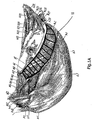
- Fig. 1 shows an example of a carcass part 1 with an incision 110 according to the first aspect of the invention.
- This carcass part 1 of slaughtered poultry comprises at least a part of the back 2.
- Not shown in fig. 1 but present in the carcass part 1 in this example, are at least a part of the rib cage and a part of the spine.
- Fig. 1 shows that the carcass part 1 comprises at least a part of the meat that is naturally present on the back 2 and on the rib cage.
- the meat on the rib cage comprises at least a part of the meat on the breast 3, that is: at least a part of the breast fillet 8.
- the carcass part 1 to be processed in the example in fig. 1 is a front half. It is however also possible to process other types of carcass parts, such as breast caps for example, using the device and method according to the first aspect of the invention.
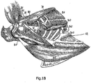
- Fig 1A and fig. 1B show the anatomy of the torso of poultry.
- the hatched part in fig. 1A shows the area in which the abdominal muscle tissue 11 lies. In some circles the muscle tissue in the hatched area in fig 1A is known in professional parlance as "ring muscle".
- the abdominal muscle tissue comprises at least the part of the m. obliquus externus abdominis, at least the part of the m. obliquus internus abdominis and at least the part of the m. transversus abdominis that fall within the hatched area of fig. 1A .
- fig. 1B shows the position of the delta bone 12.
- Fig. 1A and fig 1B are based on figures from the book "Atlas de anatom ⁇ a de las aves domesticas” [Atlas of the anatomy of domestic birds], ISBN 84-283-1138-2, published in 1981 .
- the Latin names of the muscles shown in the figures have been included in a separate list that is appended to this application.
- the carcass part 1 also comprises both wings or least parts 4 of them. This is not, however, a requirement in order to implement the method according to the first aspect of the invention.
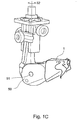
- Fig. 1C shows a product carrier 50 with a front half that has been placed onto it.
- the product carrier 50 shown in fig. 1C can pivot around axis 51 and around axis 52.
- a product carrier of this type is suitable for use in combination with all aspects of the invention that are described in this application. It is not, however, necessary to use a product carrier capable of this type of pivoting. In most cases the processing operations that are described in this application require a relative movement between the carcass part to be processed 1 and the parts of the device that directly engage on the carcass part 1 such as blades or scrapers for example.
- the desired relative movement can be achieved by having the product carrier that is holding the carcass part 1 move while having the processing components of the device remain in a mainly fixed position (naturally this is apart from any resilient moving of certain components and rotation of the rotating blades), but of course also by holding the carcass part 1 in a mainly fixed position while the processing components.
- a combination of a movement of the carcass part 1 and a movement of the processing components of the device according to the various aspects is possible in order to achieve the desired relative movement between the carcass part and the device.
- Fig. 1D and fig. 1E show a breast cap being attached to the product carrier 50.
- the product carrier 50 in fig. 1D and fig 1E is of the same type as shown in fig. 1C .
- the product carrier is provided with a hook 53 that holds the breast cap securely on the product carrier 50.
- a type of product carrier that does not have the pivoting capability of the product carrier shown can also be used when processing a breast cap.
- Fig. 1F shows a side view of an example of an alternative product carrier 50*.
- the product carrier 50* is based on the product carrier that is known from EP0254332 .
- This product carrier is only rotatable according to arrow 52*. This rotation can be controlled by control elements that engage toothed wheel 54*.
- Product carrier 50* is moveable along path 53* in conveying direction T1.
- Each of the product carriers 50* is connected to a trolley 55* that can be guided across a profile 56*.
- the trolleys 55* are mutually connected by a (diagrammatically depicted) chain or cable 57*.
- Fig. 1G shows the alternative product carrier of fig. 1F provided with a breast cap with wings as the carcass part 1 to be processed.
- Fig. 1H shows the alternative product carrier of fig. 1F provided with a breast cap without wings as the carcass part 1 to be processed. Processing of breast caps with or without wings can also take place using a product carrier 50 of the type as shown in figures 1C , 1D and 1E .
- the otherway around the product carrier 50* shown in figures 1F , 1G and 1H can also be used for processing front halves with wings, front halves without wings and the like, for example.
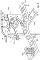
- Fig. 2 shows a first embodiment of the system and the method according to the invention.
- carcass parts 1 are arranged on product carriers 50 such as those that are known according to EP1191582 for example.
- the product carriers are advanced in conveying direction T1 along a path determined by rail 39.
- Each carcass part comprises at least one harvestable part 501.
- the harvestable part comprises breast fillet 8 and wing parts 4.
- the harvestable part 501 of the carcass part 1 is still connected to the bone parts that are present in the carcass part 1, to the rib cage in particular.
- a product carrier 50 feeds a carcass part 1 to a processing device 510.
- the processing device 510 is a filleting device as described in EP 1430780 A1 .
- the breast fillet 8 is pulled loose from the rib cage of the carcass part 1 by pulling on the wing parts 4.
- the processing device 510 then conveys the harvestable part 501, which comprises the breast fillet 8 and the wing parts 4 in this exemplary embodiment, to a pair of rotating blades 511 which separate the wing parts 4 from the breast fillet 8.
- the form of the product carrier 50 is such that the carcass part 1 to be processed only fits on it in one way. Also, guides in the processing device 510 ensure that each carcass part enters the processing device 510 in the same orientation. Consequently, each carcass part 1 that is processed by the processing device 510 arrives in the processing device in the same, predefined orientation in relation to this processing device. Also during processing of the carcass part 1 by processing device 510 the orientation of carcass part 1, and particularly that of its harvestable part 501 remains known and the same as a predefined orientation. The result of this is that the harvestable parts 501 of successive carcass parts 1 always leave the processing device 510 in the same orientation in relation to this processing device.
- the removed breast fillets 8 are received on conveyor 530.
- the orientation of the breast fillets 8 on the conveyor 530 is thus known and defined in advance. This known orientation is used in the subsequent packaging of the breast fillets 8.
- the conveyor 530 discharges onto a drop conveyor 531. This is a conveyor with a variable length in the conveying direction T2 of the conveyor.
- the breast fillet to be packaged arrives on the drop conveyor 531.
- the drop conveyor 531 conveys the breast fillet to the end of the drop conveyor 531 in its extended position.
- a discharge conveyor 552 is disposed under the drop conveyor. This discharge conveyor 552 feeds trays 550 to the location where the breast fillets 8 are placed in trays 550. Once a tray 550 has arrived in this location, it is preferable that it is restrained by a moveable stop 553 that holds the tray in its place until drop conveyor 531 has deposited a fillet 8 in it. When a drop conveyor 531 is applied this location will therefore be under the retracting part of the drop conveyor 531.
- the fillets 8 can be deposited directly from the conveyor 530 into the trays 550.
- the conveyor 530 is positioned such that it passes a short distance from the discharge point 512, where the fillets leave the processing device 510. Further, it is advantageous if the conveyor 530 comprises a part 530a that is arranged at an incline in the immediate vicinity of the discharge point 512, as shown in fig. 2 . This inclined part 530a slopes downwards in the downstream direction. In practice it has been found that the fillets 8 already hang downwards in the processing device under the force of gravity. Consequently, with a conveyor that is positioned at an incline almost the full length of the fillet comes into contact with the conveyor at almost the same time. It has been found in practice that in this way the inclined part 530a of the conveyor makes receiving the fillets in a fixed orientation more reliable.
- the trays 550 are the known shallow trays in which the fillets 8 are offered to the consumer in the supermarket.
- the shallow trays can be conveyed by conveyor 552 to a station where a preferably transparent plastic foil is applied over each filled tray.
- the fillets can also be received into a larger tray or crate which for example is used for transportation to a shop.
- the trays 550 are supplied from a destacker 560. This is of course positioned upstream relative to the drop conveyor 531.
- Fig. 3 shows a variation of the method and the system shown in fig. 2 .
- the conveyor 552 feeds the trays 550 directly to the location where the breast fillets 8 leave the processing device 510, the filleting device in this case.
- This example uses the filleting device known from EP1430780 A1 , which is suitable for use in combination with the invention.
- the conveyor 530 and the drop conveyor 531 are therefore no longer required.
- the trays 550 are fed from a destacker 560.
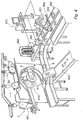
- Fig. 4 shows a second variation of the embodiment shown in fig. 2 and fig. 3 .
- a processing unit 510 removes the breast fillet 8 and the wing parts 4 from carcass part 1.
- the rest of the carcass part 502 remains held by product carrier 50.
- Product carrier 50 conveys the rest 502 of the carcass part 1 to a subsequent processing station. This is, for that matter, also the case in the embodiments shown in figures 2 , 3 and 5 .
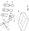
- This conveyor 530 conveys the fillets 8 to robot 520.
- This robot comprises a first arm 523 and a second arm 524. The arms 523, 524 are arranged pivotably relative to each other. At the end of the first arm 523 there is a gripper 522.
- This gripper takes the breast fillet 8 and deposits it in the tray 550.
- a conveyor 552 supplies trays from the destacker 560 to the robot 521. Stop 553 makes that an empty tray 550 cannot pass the robot before a fillet 8 has been deposited in it.
- the robot can always perform the same movement to deposit the fillet 8 in the tray 550 in the desired manner.
- the gripper 522 is made from stainless steel and is preferably arranged eccentrically and rotatable relative to the longitudinal axis of the arm 523. In the example shown the gripper 522 grips the breast fillets 8 using one or more suction pads. As an alternative the gripper 522 could in essence take the form of a hand.
- the system also comprises a checking device 450.
- This checking device can comprise an X-ray device for example, to check that no unwanted bone parts remain in the fillets 8.
- the system can also comprise an inspection station to visually inspect the harvestable part.
- Such an inspection system can have a camera that is connected to an image analysis system. In this way the harvestable parts 501, breast fillets 8 in this case, can be visually inspected for deviations. In this regard, consider, for example, bruises or pieces of skin that have not been successfully removed.
- the wing parts 4 that are separated from the breast fillet 8 are fed to conveyer 530'.
- the wing parts come to lie on the conveyor 530' in a predefined and reproducible manner.
- the right wings and the left wings do not, however, lie on the conveyor 530' in the same manner. This does not, however, have to be a problem during packaging. Good packaging methods are known where the wings lie alternately so that the total forms an attractive presentation.
- a robot can be used to deposit the wing parts 4 in trays 550, during which process the robot takes into account the difference in orientation between left wings and right wings. This is, of course, also the case in the embodiments shown in figs. 2 and 3 .
- Fig. 5 shows a variation of the embodiment shown in fig. 4 .
- the product carrier does not engage on the inside of the carcass part 1 but engages on the legs, which are still present on the carcass part in this variation.
- Fig. 6 shows a second embodiment of the system and the method according to the invention.
- the carcass part 1 to be processed is a leg.
- product carriers 50 advance the carcass parts 1 to be processed to a processing device 510.
- the legs hang next to each other in the product carrier 50, two-by-two.
- the product carrier holds the legs just below the tarsal joint.
- the processing device 510 comprises two rotating blades 511. These rotating blades 511 cut the carcass parts 1 in such a way that the thigh pieces are removed and the drumsticks remain hanging in the product carrier. In this case the thigh pieces, that are also sold as skinless thighs, form the harvestable parts 501 and the drumsticks form the rest 502 of the carcass part.
- a feed device 520 is provided that comprises a robot 521.
- the robot comprises a first arm 523 that is pivotable in a direction that is perpendicular to the longitudinal direction of the robot arm 523.
- a gripper 522 has been fitted to the robot arm 523. This gripper already grips the thigh piece 9 of the carcass part before the thigh piece 9 is separated from the drumstick 6.
- the gripper prevents the thigh piece dropping down.
- the orientation of the thigh piece 9 relative to the gripper is also directly and thereby unequivocally defined.
- the robot can now deposit the thigh piece 9 in a fed tray 550 with a single rotation of the robot arm 523.
- the orientation of the thigh piece 9 is unequivocally defined relative to the gripper, and the robot arm always carries out the same movement, the orientation in which the thigh piece 9 is deposited in the tray 550 is always unequivocally fixed. This consequently achieves an unequivocal presentation of the thigh piece in the tray.
- the trays 550 are supplied empty and removed full by a conveyor 552.
- the system according to fig. 6 therefore comprises two rotating blades 515 disposed opposite to each other and two feed devices 520 that are arranged opposite each other.
- two conveyors 552 that are arranged next to each other are then also present.
- the rotating blades, feed devices and conveyors are positioned in mirror image relative to each other.
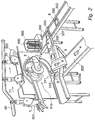
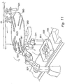
- Fig. 7 shows an overview of the systems and methods according to a third variation of the invention, where various operations are carried out in succession on a carcass part 1 in various processing devices 510.
- Each processing device 510 is provided with a robot which feeds the harvested part 501 to a tray 550 during the operation concerned.
- the trays 550 are supplied empty via a conveyor 552 and removed full.
- the entire system is controlled by a control system 570.
- the conveyors 552 can be arranged perpendicular to the conveying direction T1 of the carcass parts 1 and/or product carriers 50. An arrangement that is parallel to conveying direction T1 is also possible. Other mutual dispositions are of course also possible, depending on the layout of the entire process.
- the described embodiments of the systems and methods according to the invention can be used in the set-up shown in fig. 7 .
- Fig. 8 shows a fourth embodiment of the system and the method according to the invention.
- the harvestable parts 501 in this case drumsticks 6 for example, are placed in a buffer 580 in a predefined orientation.
- a robot 521 extracts the harvestable parts 501 one by one from the buffer and deposits them in a tray 550 in a predefined orientation.
- the robot 521 is provided with a gripper 522 for this purpose.
- the robot 521 also comprises a robot arm 523. This arm can rotate around an axis 525. Should the mutual positions of the buffer 580 and the tray 550 make it necessary, the arm 523 can also have a variable length.
- a number of drumsticks 6 are deposited into a single tray 550.
- An attractive and efficient method of depositing a number of drumsticks 6 into a single tray 550 is to lay the successive drumsticks in the tray alternately rotated 180° relative to each other. In the embodiment according to fig. 8 this is achieved by making the gripper 522 rotatable relative to the robot arm 523.
- the robot 521 in the embodiment of fig. 8 also has a second arm 524. However, it has a fixed mounting relative to the fixed world.
- Fig. 9 shows a variation of the embodiment of fig. 8 .
- two harvestable parts 501 are carried by a single product carrier.
- the harvestable parts are parts of the leg.
- the product carriers slide the harvestable parts into two adjacent slots 581, 582 of a buffer plate.
- the buffer plate 538 comprises a plurality of such slots.
- the robot 521 is provided with a gripper 522 which can take one harvestable part 501 out of a slot 581, 582 each time.
- the robot then takes the extracted harvestable part 501 to a tray 550.
- the tray 550 can receive multiple harvestable parts 501. It is, of course, also possible for the tray to receive only one harvestable part 501. In the example shown in fig. 9 the harvestable parts are each deposited in the tray rotated 180° relative to each other. Naturally another configuration can also be chosen. However, the more complicated the configuration, the greater the number of degrees of freedom the robot 521 requires.
- the system is provided with a camera 541.
- This camera can be used, for example, to check that the harvestable parts 501 come to lie in the correct position in the tray 550. It is preferable that the camera 541 is linked to an image analysis system.
- a conveyor 552 supplies empty trays 550 and removes filled trays 550.
- the variation of fig. 10 strongly resembles the one of fig. 9 .
- the gripper is, however, equipped in such a manner that it can extract two harvestable parts 501 simultaneously from adjacent slots 581, 582.
- the embodiment of fig. 11 expands on this concept.
- the gripper also simultaneously extracts two harvestable parts 501 from adjacent slots in the buffer disk 583.
- the robot now however places the simultaneously extracted harvestable parts 501 in the tray 550 at some distance from each other.
- the distance at which the harvestable parts 501 are placed in the tray relative to each other provides the space to deposit one of the two harvestable parts from a next duo of harvestable parts 501 in the tray between the two previously deposited harvestable parts. In this way a good presentation of the harvestable parts 501 in the tray 550 can be prepared.
- Fig. 12 shows a fifth embodiment of the system and the method according to the invention.
- a gripper extracts two leg parts from a product carrier 50 at the same time. Then the extracted leg parts 501 are again deposited in a tray 550, in the manner that has already been discussed in connection with figures 10 or 11 for example.
- a camera 541 checks that the harvestable parts 501, in this case the legs, have arrived in the tray in the desired manner.
- Fig. 13 shows a variation of the system that can be used for extracting and packaging drumsticks.
- the construction of the system of fig. 13 is the same as the system of fig. 12 .
- Fig. 14 shows the application of the system and the method in combination with a harvestable part 501 that has been coated.
- the presence of the coating requires the use of special product carriers 50' that damage the coating as little as possible.
- the gripper 522 that is mounted on the end of a robot arm 523 is based on the same holding principle as the special product carrier 50'.
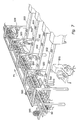
- Figs. 15-17 relate to a destacker that is suitable for use within the method and the system according to the invention.
- Fig. 15 shows an overview of the destacker 560, in which a stack 551 of trays 550 is stacked in a container 561 intended for this purpose.
- the stack of trays 551 is held by a support 562 that comprises two guides 566.
- the guides 566 can move simultaneously in a direction that is substantially perpendicular to the vertical direction of the stack of trays.
- the destacker is provided with a drive 567 to control the guides.
- each guide 566 three bearing plates 562, 563, 564 are attached.
- the front bearing plate 563 and the back bearing plate 565 are arranged at approximately the same height as the guide 566; the middle bearing plate 564 is arranged higher.
- the bearing plates of both guides point towards each other as can be seen in fig. 17 .
- Destacking takes place in the following manner: in the initial situation the stack 551 of trays 550 rests on the first bearing plate 563 (see fig. 17A ). Next both guides 566 are simultaneously moved in their longitudinal direction. The magnitude and direction of this movement are such that the middle bearing plate 564 comes to lie under the container 561. As the middle bearing plate 564 is arranged higher than the first or front bearing plate 563 the bottom tray 550 of the stack 561 is no longer supported; the middle bearing plate now supports the tray one from the bottom of the stack 551. The bottom tray 550 falls onto the conveyor 552 that is positioned under the destacker.
- the guides 566 simultaneously move further so that the stack 551 is supported by the third or back bearing plate 565. To this end the guides 566 are moved further such that the back or third bearing plate 565 moves under the container 561. On the subsequent move of the guides 566 in the opposite direction a tray 550 is once again released from the stack. In this way a tray is released on each stroke (that is a movement of the guides in a single direction).
- the second, middle, bearing plate in an advantageous embodiment, has an edge 568, 568' that presses the bottom tray of the stack downwards when the second bearing plate is moved under the stack. Two variations of the edge 568, 568' are shown in fig. 16B and fig. 16C .
- the edge 568 extends in the axial direction of the guide 566.
- the inclined parts of the edge 568 press the bottom tray in the stack down when the second bearing plate 564 starts to support the stack (except the bottom tray).
- the sides of the second bearing plate 564 that extend transverse to the axial direction of the guide 566 are provided with an inclined edge 568'. This inclined edge 568' can easily be formed by bending down the relevant edges of the bearing plate 564.
- each guide 566 comprises only bearing plates 563 and 564. After the release the guides 566 in this embodiment are not moved further in the same direction, but are moved back in an opposite direction in such a way that the stack which was first resting on the second bearing plate 564 now comes to rest on bearing plate 563 again. A subsequent movement of the guides then again releases the next tray 550. In this embodiment a tray is not released on each stroke but with each forward-and-back movement (so once every two strokes).
- the drive 570 of both guides can be realized in different ways. In practice it has been found that suitable results can be achieved using a pneumatic drive. Other drives, an electric motor combined with a toothed wheel-gear rack for example, are also conceivable.
- the invention involves a method for processing a carcass part of slaughtered poultry, this method comprising the following steps:
- the harvestable part is placed in a buffer in a predefined orientation prior to being deposited in the tray.
- the feed device comprises a conveyor and the harvestable part comes to rest on the conveyor in a predefined orientation.
- the harvestable part is deposited in the tray by means of a drop conveyor.
- the feed device comprises a robot.
- the robot deposits the harvestable part in the tray.
- the robot holds the harvestable part during separation of the harvestable part from the rest of the carcass part. If in this preferred embodiment the robot deposits the harvestable part in the tray and the robot holds the harvestable part during separation of the harvestable part from the rest of the carcass part, preferably the robot holds the harvestable part from separation of the harvestable part from the rest of the carcass part until the harvestable part is deposited in the tray.
- the robot comprises at least a first arm.
- this first arm is rotatable around a first rotation axis, this first rotation axis being arranged substantially perpendicular to the longitudinal direction of the first arm.
- the first arm has a variable length.
- the robot further has a second arm which is hingedly connected to the first arm, this second arm having a fixed, extendable or pivotable mounting.
- the robot In the preferred embodiment of the method according to the invention in which the feed device comprises a robot, preferably the robot always makes the same movement when successively depositing a number of harvestable parts of carcass parts.
- the feed device comprises a gripper, which gripper is used to handle the harvestable part while the harvestable part is fed into the tray.
- the gripper is made of stainless steel.
- the gripper is eccentrically mounted on a robot arm.
- the gripper is eccentrically mounted on a robot arm and the gripper is rotatable relative to the robot arm.
- the gripper holds the harvestable part of the carcass part during separation of the harvestable part from the rest of the carcass part.
- the harvestable part is checked for unwanted bone parts.
- the check for unwanted bone parts is performed using an X-ray device.
- the harvestable part is visually inspected.
- the visual inspection is carried out with the aid of a camera.
- the check or inspection is carried out after the harvestable part has been deposited into the tray.
- a number of harvestable parts from one or more carcass parts are deposited in a tray.
- the harvestable parts are deposited in the tray in a predefined position in relation to each other.
- the tray is moved between a first harvestable part and a subsequent harvestable part being deposited in the tray in order to achieve the desired mutual position of both harvestable parts in the tray.
- a number of harvestable parts are deposited in the tray simultaneously.
- the harvestable part of the carcass part is a breast fillet.
- the harvestable part of the carcass part is a leg or a part of a leg.
- the harvestable part has been provided with a coating.
- the tray also forms the transport packaging of the harvestable part.
- the tray is fed from a destacker to the location at which a harvestable part will be deposited in the tray.
- this method further comprising the following steps:
- the invention further involves a system for processing a carcass part of slaughtered poultry, this system comprising:
- the system also comprises a buffer for receiving one or more harvestable parts prior to their being deposited in the tray, in which the orientation of each harvestable part is known during the stay of the harvestable part in the buffer.
- the feed device comprises a conveyor.
- the feed device also comprises a drop conveyor for depositing the harvestable part in the tray.
- the feed device comprises a robot.
- the robot comprises a first arm and a second arm.
- the second arm is pivotable around a first rotation axis, which first rotation axis is arranged substantially perpendicular to the longtitudinal direction of the second arm.
- at least the second arm is of variable length.
- the first arm of the robot has a fixed mounting.
- the feed device comprises a gripper for handling the harvestable part while the harvestable part is being fed into the tray.
- the gripper is made of stainless steel.
- the gripper is mounted eccentrically on a robot arm.
- the gripper is mounted eccentrically on a robot arm and the gripper is rotable relative to the robot arm.
- the system also comprises a checking device for checking the harvestable part for unwanted bone parts.
- the checking device comprises an X-ray device.
- the system also comprises an inspection station to visually inspect the harvestable part.
- the inspection station comprises a camera.
- the system also comprises a displacing device to displace the tray between a first harvestable part being deposited in the tray and a subsequent harvestable part in order to achieve the desired mutual position of both harvestable parts in the tray.
- the system also comprises a destacker to feed a tray to the location in which a harvestable part will be deposited in the tray.
- the destacker comprises:
- intercostales externi B13 - Mm. subcostales; B14 - M. pectoralis superficialis; B15 - M. pectoralis profundus; B16 - M. coracobrachialis externus; B17 - M. coracobrachialis internus; B18 - M. coracobrachialis dorsalus; B19 - M. subscapularis.
Claims (15)
- Procédé de traitement d'une partie de carcasse (1) de volaille abattue,
ce procédé comprenant l'étape suivante :- exécution d'un traitement sur la partie de carcasse (1) à l'aide d'un dispositif de traitement (510),dans lequel la partie de carcasse (1) a une position et une orientation prédéfinies par rapport au dispositif de traitement (510), traitement au cours duquel au moins une partie récupérable (501) de la partie de carcasse (1) est séparée du reste de la partie de carcasse (1),
caractérisé en ce que le procédé comprend en outre les étapes consistant à :- transporter la partie récupérable (501) vers un plateau (550) en utilisant un dispositif d'alimentation, où l'orientation de la partie récupérable (501) par rapport au dispositif d'alimentation est connue à l'avance sur la base de l'orientation de la partie récupérable (501) par rapport au dispositif de traitement (510), dans lequel le plateau (550) sert d'emballage,- déposer la partie récupérable (501) de la partie de carcasse (1) dans le plateau (550) dans une position prédéfinie et dans une orientation prédéfinie. - Procédé selon la revendication 1,
dans lequel la partie récupérable (501) est placée dans un tampon (580) dans une orientation prédéfinie avant d'être déposée dans le plateau (550),
et/ou
dans lequel le dispositif d'alimentation comprend un convoyeur (530) et la partie récupérable (501) vient se poser sur le convoyeur dans une orientation prédéfinie, dans lequel de préférence, la partie récupérable (501) est déposée dans le plateau (550) au moyen d'un convoyeur de chute (531). - Procédé selon l'une quelconque des revendications précédentes, dans lequel le dispositif d'alimentation comprend un robot (520).
- Procédé selon la revendication 3,
dans lequel le robot (520) dépose la partie récupérable (501) dans le plateau (550),
et/ou dans lequel le robot (520) maintient la partie récupérable (501) pendant la séparation de la partie récupérable (501) du reste de la partie de carcasse (1),
dans lequel procédé, de préférence, le robot (520) maintient la partie récupérable (501) depuis la séparation de la partie récupérable (501) du reste de la partie de carcasse (1) jusqu'à ce que la partie récupérable (501) soit déposée dans le plateau (550). - Procédé selon la revendication 3,
dans lequel le robot (520) comprend au moins un premier bras (523),
lequel premier bras (523) est de préférence rotatif autour d'un premier axe de rotation, ce premier axe de rotation étant disposé sensiblement perpendiculairement à la direction longitudinale du premier bras (523),
dans lequel, de préférence, le premier bras (523) a une longueur variable,
dans lequel procédé, facultativement, le robot (520) comporte en outre un second bras (524) qui est relié de manière articulée au premier bras (523), ce second bras (524) ayant un montage fixe, extensible ou pivotant. - Procédé selon la revendication 3,
dans lequel le robot (520) effectue toujours le même mouvement lorsqu'il dépose successivement un certain nombre de parties récupérables (501) de parties de carcasse (1). - Procédé selon l'une quelconque des revendications précédentes,
dans lequel le dispositif d'alimentation comprend un préhenseur (522), lequel préhenseur (522) est utilisé pour manipuler la partie récupérable (501) pendant que la partie récupérable (501) est alimentée dans le plateau (550),
dans lequel procédé, de préférence, le préhenseur (522) est fabriqué en acier inoxydable,
dans lequel procédé, de préférence, le préhenseur (522) est monté de manière excentrique sur un bras de robot, et le préhenseur (522) pouvant éventuellement tourner par rapport au bras de robot,
dans lequel procédé, de préférence, le préhenseur (522) maintient la partie récupérable (501) de la partie de carcasse (1) pendant la séparation de la partie récupérable (501) du reste de la partie de carcasse (1). - Procédé selon l'une quelconque des revendications précédentes,
dans lequel on contrôle que la partie récupérable (501) ne contient pas de parties osseuses indésirables,
lequel contrôle des parties osseuses indésirables est de préférence effectué à l'aide d'un dispositif à rayons X, lequel contrôle ou inspection est de préférence effectué après que la partie récupérable (501) ait été déposée dans le plateau (550),
et/ou
dans lequel la partie récupérable (501) est inspectée visuellement,
laquelle inspection visuelle est de préférence effectuée à l'aide d'une caméra (541),
dans lequel procédé l'inspection est de préférence effectuée après que la partie récupérable (501) a été déposée dans le plateau (550). - Procédé selon l'une quelconque des revendications précédentes,
dans lequel un certain nombre de parties récupérables (501) provenant d'une ou plusieurs parties de carcasse (1) sont déposées dans un plateau (550),
les parties récupérables (501) étant de préférence déposées dans le plateau (550) dans une position prédéfinie les unes par rapport aux autres,
dans lequel procédé, de préférence, le plateau (550) est déplacé entre une première partie récupérable et une partie récupérable suivante déposées dans le plateau (550) afin d'obtenir la position mutuelle souhaitée des deux parties récupérables (501) dans le plateau (550),
dans lequel procédé, éventuellement, un certain nombre de parties récupérables (501) sont déposées dans le plateau (550) simultanément. - Procédé selon l'une quelconque des revendications précédentes,
dans lequel la partie récupérable (501) de la partie de carcasse (1) est un filet (8), une patte ou une partie de la patte,
et/ou dans lequel procédé la partie récupérable (501) a été pourvue d'un revêtement,
et/ou dans lequel procédé le plateau (550) constitue également l'emballage de transport de la partie récupérable (501) . - Système de traitement d'une partie de carcasse (1) de volaille abattue,
ce système comprenant :- un support de produit destiné à supporter la partie de carcasse (1),- un dispositif de traitement (510) pour effectuer un traitement sur la partie de carcasse (1), dans lequel la partie de carcasse (1) est dans une position et une orientation prédéfinies par rapport à la direction de traitement, traitement au cours duquel au moins une partie récupérable (501) de la partie de carcasse (1) est séparée du reste de la partie de carcasse (1),caractérisé en ce que le système comprend en outre- un dispositif d'alimentation motorisé pour alimenter la partie récupérable (501) de la partie de carcasse (1) dans un plateau (550), où l'orientation de la partie récupérable (501) par rapport au dispositif d'alimentation est connue à l'avance sur la base de l'orientation de la partie récupérable (501) par rapport au dispositif de traitement (510),- une station d'emballage pour tenir un plateau (550) dans lequel le dispositif d'alimentation peut déposer la partie récupérable (501) dans une position prédéfinie et avec une orientation prédéterminée, dans laquelle le plateau (550) sert d'emballage. - Système selon la revendication 11,
dans lequel le système comprend également un tampon (580) pour recevoir une ou plusieurs parties récupérables (501) avant leur dépôt dans le plateau (550), dans lequel l'orientation de chaque partie récupérable (501) est connue pendant le séjour de la partie récupérable (501) dans le tampon (580),
et/ou dans lequel système le dispositif d'alimentation comprend un convoyeur (530), et de préférence le dispositif d'alimentation comprend également un convoyeur de chute (531) pour déposer la partie récupérable (501) dans le plateau (550). - Système selon l'une quelconque des revendications 11 à 12,
dans lequel le dispositif d'alimentation comprend un robot (520), lequel robot (520) comprend de préférence un premier bras (523) et un second bras (524),
dans lequel système, de préférence, le second bras (524) peut pivoter autour d'un premier axe d'orientation,
lequel premier axe d'orientation est disposé sensiblement perpendiculairement à la direction longitudinale du second bras (524),
dans lequel système, de préférence, au moins le second bras (524) est de longueur variable,
dans lequel système, de préférence, le premier bras (523) du robot (520) a un montage fixe. - Système selon l'une quelconque des revendications 11 à 13,
dans lequel le dispositif d'alimentation comprend un préhenseur (522) pour la manipulation de la partie récupérable (501) pendant que la partie récupérable (501) est alimentée dans le plateau (550), le préhenseur (522) étant de préférence réalisée en acier inoxydable,
dans lequel système, de préférence, le préhenseur (522) est montée de manière excentrique sur un bras de robot, et le préhenseur (522) pouvant éventuellement tourner par rapport au bras de robot. - Système selon l'une quelconque des revendications 11 à 14,
dans lequel le système comprend en outre un dispositif de contrôle pour vérifier la présence de parties osseuses indésirables dans la partie récupérable (501), lequel dispositif de contrôle comprend de préférence un dispositif à rayons X,
et/ou
dans lequel le système comprend en outre une station d'inspection pour inspecter visuellement la partie récupérable (501), laquelle station d'inspection comprend de préférence une caméra (541),
et/ou
dans lequel le système comprend également un dispositif de déplacement pour déplacer le plateau (550) entre une première partie récupérable (501) déposée dans le plateau (550) et une partie récupérable (501) suivante afin d'obtenir la position mutuelle souhaitée des deux parties récupérables (501) dans le plateau (550).
Applications Claiming Priority (4)
| Application Number | Priority Date | Filing Date | Title |
|---|---|---|---|
| NL1030638 | 2005-12-09 | ||
| NL1030671A NL1030671C2 (nl) | 2005-12-14 | 2005-12-14 | Werkwijze en inrichting voor het bewerken van een karkasdeel van geslacht gevogelte. |
| EP06835655.9A EP1956919B1 (fr) | 2005-12-09 | 2006-12-11 | Procede et dispositif de traitement d'une carcasse de volaille abattue |
| PCT/NL2006/000632 WO2007067052A2 (fr) | 2005-12-09 | 2006-12-11 | Procede et dispositif de traitement d’une carcasse de volaille abattue |
Related Parent Applications (3)
| Application Number | Title | Priority Date | Filing Date |
|---|---|---|---|
| EP06835655.9 Division | 2006-12-11 | ||
| EP06835655.9A Division EP1956919B1 (fr) | 2005-12-09 | 2006-12-11 | Procede et dispositif de traitement d'une carcasse de volaille abattue |
| EP06835655.9A Division-Into EP1956919B1 (fr) | 2005-12-09 | 2006-12-11 | Procede et dispositif de traitement d'une carcasse de volaille abattue |
Publications (3)
| Publication Number | Publication Date |
|---|---|
| EP2356908A2 EP2356908A2 (fr) | 2011-08-17 |
| EP2356908A3 EP2356908A3 (fr) | 2013-07-03 |
| EP2356908B1 true EP2356908B1 (fr) | 2021-08-25 |
Family
ID=37758745
Family Applications (7)
| Application Number | Title | Priority Date | Filing Date |
|---|---|---|---|
| EP11160174.6A Active EP2332418B1 (fr) | 2005-12-09 | 2006-12-11 | Procédé et dispositif de traitement d'une pièce de carcasse de volaille abattue |
| EP11160158.9A Active EP2332417B1 (fr) | 2005-12-09 | 2006-12-11 | Procédé et dispositif de traitement d'une carcasse de volaille abattue |
| EP11160215.7A Active EP2353396B1 (fr) | 2005-12-09 | 2006-12-11 | Procédé et dispositif de traitement d'une pièce de carcasse de volaille abattue |
| EP11160228.0A Active EP2356908B1 (fr) | 2005-12-09 | 2006-12-11 | Procédé et dispositif de traitement d'une pièce de carcasse de volaille abattue |
| EP06835655.9A Active EP1956919B1 (fr) | 2005-12-09 | 2006-12-11 | Procede et dispositif de traitement d'une carcasse de volaille abattue |
| EP11160202.5A Withdrawn EP2332419A3 (fr) | 2005-12-09 | 2006-12-11 | Procédé et dispositif de traitement d'une pièce de carcasse de volaille abattue |
| EP11160209.0A Pending EP2332420A3 (fr) | 2005-12-09 | 2006-12-11 | Procédé et dispositif de traitement d'une pièce de carcasse de volaille abattue |
Family Applications Before (3)
| Application Number | Title | Priority Date | Filing Date |
|---|---|---|---|
| EP11160174.6A Active EP2332418B1 (fr) | 2005-12-09 | 2006-12-11 | Procédé et dispositif de traitement d'une pièce de carcasse de volaille abattue |
| EP11160158.9A Active EP2332417B1 (fr) | 2005-12-09 | 2006-12-11 | Procédé et dispositif de traitement d'une carcasse de volaille abattue |
| EP11160215.7A Active EP2353396B1 (fr) | 2005-12-09 | 2006-12-11 | Procédé et dispositif de traitement d'une pièce de carcasse de volaille abattue |
Family Applications After (3)
| Application Number | Title | Priority Date | Filing Date |
|---|---|---|---|
| EP06835655.9A Active EP1956919B1 (fr) | 2005-12-09 | 2006-12-11 | Procede et dispositif de traitement d'une carcasse de volaille abattue |
| EP11160202.5A Withdrawn EP2332419A3 (fr) | 2005-12-09 | 2006-12-11 | Procédé et dispositif de traitement d'une pièce de carcasse de volaille abattue |
| EP11160209.0A Pending EP2332420A3 (fr) | 2005-12-09 | 2006-12-11 | Procédé et dispositif de traitement d'une pièce de carcasse de volaille abattue |
Country Status (7)
| Country | Link |
|---|---|
| US (7) | US8192258B2 (fr) |
| EP (7) | EP2332418B1 (fr) |
| JP (7) | JP5197378B2 (fr) |
| BR (4) | BRPI0622404B1 (fr) |
| DK (5) | DK1956919T3 (fr) |
| ES (1) | ES2559271T3 (fr) |
| WO (1) | WO2007067052A2 (fr) |
Families Citing this family (63)
| Publication number | Priority date | Publication date | Assignee | Title |
|---|---|---|---|---|
| BRPI0622404B1 (pt) * | 2005-12-09 | 2015-11-24 | Stork Pmt | dispositivo e método para processar uma parte da carcaça da ave abatida |
| NL1034027C2 (nl) | 2007-06-22 | 2008-12-23 | Stork Pmt | Inrichting en werkwijze voor het in positie brengen en het aanbrengen van een borstkap van een geslacht gevogelte op een productdrager. |
| NL2001534C2 (nl) * | 2008-04-29 | 2009-10-30 | Stork Pmt | Inrichting, systeem en werkwijze voor het schoonmaken van een karkas of karkasdeel van geslacht gevogelte. |
| NL1036646C2 (en) | 2009-02-13 | 2010-08-16 | Meijn Food Proc Technology B V | Filleting device and method for harvesting fillets. |
| NL2003900C2 (en) * | 2009-12-03 | 2011-06-06 | Stork P M T B V | Device and method for processing a carcass part of slaughtered poultry. |
| BR122015030044A2 (pt) * | 2009-12-17 | 2016-05-17 | Marel Meat Processing Bv | dispositivo transportador de partes de perna de porco abatido, e, método para transportar partes individuais de perna de porco |
| DE202009017070U1 (de) * | 2009-12-17 | 2010-04-22 | Janssen, Jörg | Vorrichtung zum Entfernen eines Geflügelbrustknorpels |
| EP2353395A1 (fr) * | 2010-02-07 | 2011-08-10 | Valka Ehf | Appareil de traitement des aliments pour détecter et découper les tissus des articles alimentaires |
| NL2004521C2 (en) * | 2010-04-07 | 2011-10-11 | Marel Stork Poultry Proc Bv | SLAUGHTERING INSTALLATION AND METHOD. |
| NL2004662C2 (en) | 2010-05-04 | 2011-11-08 | Meyn Food Proc Technology Bv | A method for filleting poultry or poultry parts and a filleting system for such poultry or poultry parts. |
| DE102010047660B4 (de) * | 2010-09-30 | 2016-09-01 | Nordischer Maschinenbau Rud. Baader Gmbh + Co. Kg | Vorrichtung und Verfahren zum vollständigen Lösen zumindest eines Teils des Brustknorpels von einer vom Brustfleisch befreiten Geflügelkarkasse |
| WO2012056793A1 (fr) | 2010-10-27 | 2012-05-03 | 株式会社前川製作所 | Procédé de désossage et appareil de désossage de tranches avec os à l'aide de rayons x |
| NL2006313C2 (en) * | 2011-02-28 | 2012-08-29 | Meyn Food Proc Technology Bv | Method and apparatus for harvesting a backmeat of a carcass or carcass part of slaughtered poultry. |
| NL2007492C2 (en) * | 2011-09-28 | 2013-04-02 | Marel Stork Poultry Proc Bv | Carrier for supporting a carcass part of slaughtered poultry. |
| NL2007506C2 (en) * | 2011-09-29 | 2013-04-02 | Meyn Food Proc Technology Bv | Poultry processing device and method for poultry processing. |
| NL2007888C2 (en) † | 2011-11-29 | 2013-05-30 | Meyn Food Proc Technology Bv | Deboner for poultry parts, such as thighs or drumsticks. |
| NL2008001C2 (en) * | 2011-12-20 | 2013-06-24 | Meyn Food Proc Technology Bv | Method and scraper for releasing tissue connections between a fillet and a carcass of slaughtered poultry. |
| ES2528232T3 (es) * | 2011-12-23 | 2015-02-06 | Nordischer Maschinenbau Rud. Baader Gmbh + Co. Kg | Dispositivo y procedimiento para separar completamente de la canal filetes de pechuga ya separados parcialmente de la canal de un cuerpo de ave eviscerado |
| NL2008956C2 (en) * | 2012-06-07 | 2013-12-10 | Meyn Food Proc Technology Bv | Residual fat remover and method for removing residual fat of poultry fillets. |
| US9032615B2 (en) | 2012-07-31 | 2015-05-19 | Freescale Semiconductor, Inc. | Method for forming an electrical connection between metal layers |
| US8535124B1 (en) | 2012-10-17 | 2013-09-17 | Remington Holdings Llc | Poultry tender tendon clipper |
| NL2009782C2 (en) * | 2012-11-09 | 2014-05-12 | Marel Stork Poultry Proc Bv | Device and method for processing carcass parts of slaughtered poultry. |
| PL3102040T3 (pl) | 2014-02-07 | 2018-12-31 | Linco Food Systems A/S | Urządzenie pozycjonujące do pozycjonowania, przenoszonych w szeregu w kierunku przenoszenia wzdłuż odcinka przenoszenia, nóżek drobiowych oraz obejmujący pozycjonowanie sposób zdejmowania mięsa udka z nóżek drobiowych |
| WO2016002631A1 (fr) | 2014-06-30 | 2016-01-07 | 株式会社前川製作所 | Dispositif d'incision d'épaule et procédé d'incision d'épaule |
| EP3162213B1 (fr) | 2014-06-30 | 2018-08-15 | Mayekawa Mfg. Co., Ltd. | Dispositif d'incision scapulaire |
| CA2970065A1 (fr) | 2014-12-08 | 2016-06-16 | Cima Labs Inc. | Formes galeniques en granules a liberation immediate, a effet anti-abus |
| NL2014037B1 (en) * | 2014-12-22 | 2016-10-12 | Meyn Food Proc Technology Bv | Processing line and method for inspecting a poultry carcass and/or a viscera package taken out from the poultry carcass. |
| US11344036B2 (en) | 2015-03-02 | 2022-05-31 | Valka Ehf | Apparatus for processing and grading food articles and related methods |
| US11259531B2 (en) | 2015-03-02 | 2022-03-01 | Valka Ehf | Apparatus for processing and grading food articles and related methods |
| US20220061340A1 (en) | 2015-03-02 | 2022-03-03 | Valka Ehf | Apparatus for processing and grading food articles and related methods |
| NL2014512B1 (en) * | 2015-03-24 | 2017-01-19 | Meyn Food Proc Technology Bv | Apparatus for mechanically processing an organ or organs taken out from slaughtered poultry. |
| USD775932S1 (en) * | 2015-03-24 | 2017-01-10 | Meyn Beheer B.V. | Magnetic carrier for a rehanger |
| US9596863B2 (en) * | 2015-07-24 | 2017-03-21 | Marel Meat Processing Inc. | Automatic leg skinner |
| NL2015235B1 (en) * | 2015-07-29 | 2017-02-20 | Marel Stork Poultry Proc Bv | Device and method for separating a wishbone from a poultry carcass. |
| PL3205213T3 (pl) * | 2016-02-12 | 2019-09-30 | Linco Food Systems A/S | Urządzenie do odcinania skrzydeł i sposób oddzielania skrzydeł lub części skrzydeł |
| NL2016478B1 (en) | 2016-03-23 | 2017-10-06 | Marel Stork Poultry Proc Bv | System for separating breast meat from at least a part of a keel bone of a carcass part of slaughtered poultry. |
| NL2016700B1 (en) * | 2016-04-29 | 2017-11-16 | Marel Stork Poultry Proc Bv | System and method for measuring a shoulder joint position of a carcass part of slaughtered poultry. |
| NL2016723B1 (en) * | 2016-05-03 | 2017-11-10 | Marel Stork Poultry Proc Bv | Back meat harvester for harvesting back meat from a carcass part of slaughtered poultry |
| US9827678B1 (en) * | 2016-05-16 | 2017-11-28 | X Development Llc | Kinematic design for robotic arm |
| US9827677B1 (en) * | 2016-05-16 | 2017-11-28 | X Development Llc | Robotic device with coordinated sweeping tool and shovel tool |
| NL2017236B1 (en) | 2016-07-25 | 2018-01-31 | Meyn Food Processing Tech Bv | Method and device for processing a carcass part of slaughtered poultry in a processing line |
| NL2017244B1 (en) * | 2016-07-27 | 2018-02-01 | Meyn Food Processing Tech Bv | Filleting device |
| WO2019002255A1 (fr) * | 2017-06-27 | 2019-01-03 | Teknologisk Institut | Système de coupe doté d'une lame de couteau incurvée pour désosser de la viande |
| PL3545770T3 (pl) * | 2017-10-06 | 2022-06-13 | Mayekawa Mfg. Co., Ltd. | Urządzenie zaciskowe do mięsa z nogi na kości, urządzenie ładujące do mięsa z nogi na kości i sposób zaciskania mięsa z nogi na kości |
| HUE055804T2 (hu) * | 2017-10-06 | 2021-12-28 | Maekawa Seisakusho Kk | Rendszer csonton lévõ láb-hús betöltéséhez |
| KR101825425B1 (ko) | 2017-11-01 | 2018-02-05 | 이국표 | 닭 가슴살 가공장치 |
| NL2019926B1 (en) * | 2017-11-16 | 2019-05-22 | Meyn Food Processing Tech Bv | Deskinning apparatus and method for deskinning a poultry leg or part of a poultry leg |
| JP7129173B2 (ja) * | 2018-02-14 | 2022-09-01 | 株式会社前川製作所 | 骨付き肢肉の骨肉分離装置及び骨付き肢肉の骨肉分離方法 |
| KR102121650B1 (ko) * | 2018-03-14 | 2020-06-10 | 주식회사 태진 | 도계의 장각 발골시스템 |
| US11388906B2 (en) * | 2018-03-29 | 2022-07-19 | Nordischer Maschinenbau Rud. Baader Gmbh + Co. Kg | Arrangement and method for skinning poultry parts containing the poultry breast |
| BR102019008827A2 (pt) | 2018-04-30 | 2019-11-05 | Remington Holdings Llc | removedor de pele de aves com correia |
| GB201810055D0 (en) | 2018-06-19 | 2018-08-08 | Ishida Europe Ltd | Method and system for processing poultry portions |
| PL3653059T3 (pl) * | 2018-10-05 | 2022-05-16 | Mayekawa Mfg. Co., Ltd. | Urządzenie zaciskające do mięsa z kończyny z kością, urządzenie ładujące do mięsa z kończyny z kością i sposób zaciskania mięsa z kończyny z kością |
| AU2019229374A1 (en) * | 2018-11-02 | 2020-05-21 | Robotic Technologies Limited | A carcass processing assembly |
| EP3689147A1 (fr) | 2019-01-29 | 2020-08-05 | Nordischer Maschinenbau Rud. Baader GmbH + Co. KG | Dispositif et procédé de séparation d'au moins un filet de poitrine d'une carcasse de volaille éviscérée ou d'une partie dudit filet de poitrine avec une carcasse de volaille ou d'un tendon relié à une partie dudit filet de poitrine ainsi qu'unité d'outil correspondant |
| PL3729968T3 (pl) * | 2019-04-25 | 2022-04-11 | Nordischer Maschinenbau Rud. Baader Gmbh + Co. Kg | Urządzenie transportowe do transportu wypatroszonych tuszek drobiowych lub ich części |
| GB201906418D0 (en) | 2019-05-07 | 2019-06-19 | Valka Ehf | Conveyor system and method |
| US11633848B2 (en) | 2019-07-31 | 2023-04-25 | X Development Llc | Independent pan of coaxial robotic arm and perception housing |
| NL2024085B1 (en) * | 2019-10-23 | 2021-07-13 | Meyn Food Processing Tech Bv | Deskinning apparatus and method for deskinning a poultry leg or part of a poultry leg |
| WO2021156522A1 (fr) * | 2020-02-06 | 2021-08-12 | Diseño Y Construccion De Maquinaria Automatizada, S.L. | Station automatisée pour le salage de morceaux de viande et procédé de fonctionnement de celle-ci |
| KR102363078B1 (ko) * | 2020-10-21 | 2022-02-14 | 박의태 | 육계의 타케팅 포지션 분석을 통한 컷팅 콘트롤 시스템 |
| US11599984B2 (en) * | 2021-04-29 | 2023-03-07 | Syscom, Inc. | Methods and apparatus for detecting defects for poultry piece grading |
| JP2024021335A (ja) * | 2022-08-03 | 2024-02-16 | 株式会社前川製作所 | スクレーパ装置 |
Citations (2)
| Publication number | Priority date | Publication date | Assignee | Title |
|---|---|---|---|---|
| EP1430780A1 (fr) * | 2002-12-20 | 2004-06-23 | Stork Pmt B.V. | Procédé et dispositif pour traiter une partie de carcasse de volailles abattues |
| WO2005051812A1 (fr) * | 2003-10-28 | 2005-06-09 | Aew Delford Systems | Organe de prehension et de transfert ameliore |
Family Cites Families (54)
| Publication number | Priority date | Publication date | Assignee | Title |
|---|---|---|---|---|
| US2243951A (en) * | 1939-03-07 | 1941-06-03 | Gehlke Henry Charles | Method of dividing a chicken |
| US3122780A (en) * | 1960-12-30 | 1964-03-03 | Asa B Segur | Poultry meat removal method |
| US3531825A (en) * | 1967-06-14 | 1970-10-06 | Asa B Segur | Apparatus for de-boning raw poultry meat |
| US3570050A (en) * | 1968-03-26 | 1971-03-16 | Pillsbury Co | Process for removing meat from bones |
| US3624863A (en) * | 1970-05-08 | 1971-12-07 | Geno N Gasbarro | Poultry cutting apparatus |
| DE2031875C3 (de) | 1970-06-27 | 1978-11-30 | Gewerkschaft Eisenhuette Westfalia, 4670 Luenen | Kratzer für Kettenkratzförderer |
| US3902221A (en) * | 1972-01-12 | 1975-09-02 | Gainesville Machine Company In | Eviscerator apparatus and method |
| US3787926A (en) * | 1972-05-24 | 1974-01-29 | Pillsbury Co | Apparatus for cutting and packing poultry |
| NL8300907A (nl) * | 1983-03-11 | 1984-10-01 | Stork Pmt | Inrichting voor het afscheiden van de vleesdelen van het borststuk van geslacht gevogelte. |
| NL8402165A (nl) * | 1984-07-06 | 1986-02-03 | Meyn Pieter | Werkwijze en inrichting voor het verwijderen van borstvlees van een gevogeltekarkas. |
| DE3444430C1 (de) * | 1984-12-06 | 1986-04-03 | Nordischer Maschinenbau Rud. Baader GmbH + Co KG, 2400 Lübeck | Verfahren zum Gewinnen des Fleisches von Gefluegel und Vorrichtung zur Durchfuehrung des Verfahrens |
| FR2593676B1 (fr) * | 1986-02-04 | 1990-05-11 | Servajean Roger | Machine pour l'evisceration automatique des volailles |
| NL8601921A (nl) | 1986-07-24 | 1988-02-16 | Stork Pmt | Opzetsteun. |
| EP0390979A1 (fr) * | 1989-04-07 | 1990-10-10 | Linco Holland Engineering B.V. | Méthode et dispositif pour le transport d'objets en circuit fermé |
| DE4008719A1 (de) * | 1990-03-19 | 1991-09-26 | Nordischer Maschinenbau | Verfahren zum filetieren von gefluegelkoerpern |
| JPH0513180U (ja) * | 1991-03-08 | 1993-02-23 | ゴーデツクス株式会社 | 食鳥の手羽付胸肉を手羽と胸肉とに切断分離する装置 |
| JPH0793862B2 (ja) * | 1991-07-16 | 1995-10-11 | リンコ・ジャパン株式会社 | ブレストプロセッサー |
| NL9200037A (nl) * | 1992-01-10 | 1993-08-02 | Stork Pmt | Werkwijze en inrichting voor het fileren van de romp van een geslachte vogel. |
| US5154665A (en) * | 1992-01-22 | 1992-10-13 | Hazenbroek Jacobus E | On-line poultry thigh remover |
| DE4304781C1 (de) * | 1993-02-17 | 1994-09-22 | Nordischer Maschinenbau | Verfahren zum Abtrennen der Flügel von Geflügelkörpern |
| DE4413683C2 (de) * | 1994-04-20 | 1996-07-04 | Nordischer Maschinenbau | Einrichtung zum Bearbeiten der Körper geschlachteten Geflügels |
| NL9401198A (nl) * | 1994-07-21 | 1996-03-01 | Stork Pmt | Werkwijze en inrichting voor het fileren van de romp van geslacht gevogelte. |
| US5466185A (en) * | 1994-08-08 | 1995-11-14 | Foodcraft Equipment Company | Removing breast meat from poultry |
| US5429549A (en) * | 1994-10-05 | 1995-07-04 | Systemate Holland, B.V. | Sequential wing remover |
| US5472377A (en) * | 1995-01-19 | 1995-12-05 | Tyson Holding Company | Poultry processing method, apparatus, and product |
| US5697837A (en) * | 1995-07-17 | 1997-12-16 | Sytemate Holland, B.V. | Poultry breast filleting apparatus |
| NL1000935C2 (nl) * | 1995-08-04 | 1997-02-06 | Stork Pmt | Inrichting en werkwijze voor het bewerken van een slachtdier. |
| NL1002831C2 (nl) * | 1996-04-10 | 1997-10-14 | Meyn Maschf | Inrichting voor het fileren van het borststuk van geslacht gevogelte. |
| GB9712015D0 (en) * | 1997-06-11 | 1997-08-06 | Filar Limited | Procedure and apparatus for deboning poultry |
| FR2780172B1 (fr) | 1998-06-17 | 2000-09-08 | Renault | Dispositif de montage d'une pedale d'un vehicule automobile |
| NL1010930C1 (nl) * | 1998-12-31 | 2000-07-03 | Stork Pmt | Werkwijze en inrichting voor het verwerken van slachtproducten. |
| KR100414611B1 (ko) | 1999-03-09 | 2004-01-07 | 동경 엘렉트론 주식회사 | 반도체 장치의 제조 방법 |
| NL1014845C1 (nl) * | 1999-06-11 | 2000-12-12 | Stork Pmt | Inrichting voor het verwerken van een slachtproduct. |
| US6322438B1 (en) * | 1999-07-15 | 2001-11-27 | Systemate Group, B.V. | Poultry leg and thigh processor |
| NL1012683C2 (nl) | 1999-07-23 | 2001-01-24 | Stork Pmt | Werkwijze voor het winnen van een binnenfilet van een gevogeltekarkasdeel, en inrichting voor het bewerken van het gevogeltekarkasdeel. |
| US6283847B1 (en) * | 2000-02-10 | 2001-09-04 | Allan Todd Berry | Poultry breast cartilage harvesting system |
| EP1351577B1 (fr) * | 2001-01-16 | 2006-06-07 | Scanvaegt International A/S | Table de preparation |
| JP3497476B2 (ja) * | 2001-01-30 | 2004-02-16 | 株式会社前川製作所 | 中抜き屠体のハービング方法とその装置 |
| US6520317B2 (en) * | 2001-04-27 | 2003-02-18 | Abb Inc. | Packaging and casing system |
| DE10125737A1 (de) * | 2001-05-16 | 2002-11-21 | Schill Maja Masch | Vorrichtung zum Abschwarten und Enthäuten von Behandlungsgut |
| DK175567B1 (da) * | 2001-07-03 | 2004-12-06 | Slagteriernes Forskningsinst | Fremgangsmåde og apparat til friskæring af indre knogler i en forende |
| DE10241334B4 (de) | 2002-09-04 | 2017-01-05 | Maja-Maschinenfabrik Hermann Schill Gmbh & Co. Kg | Luftreinigungsvorrichtung für Abschwartungs-, Enthäutungs- und/oder Entvliesmaschinen |
| WO2004052106A1 (fr) * | 2002-12-11 | 2004-06-24 | Mayekawa Mfg.Co.,Ltd. | Equipement de traitement de desossement automatique pour la moitie superieure de corps de poulet abattu |
| JP4327099B2 (ja) * | 2003-02-03 | 2009-09-09 | 株式会社前川製作所 | 食肉脱骨装置 |
| NL1022858C2 (nl) * | 2003-03-06 | 2004-09-16 | Meyn Food Proc Technology Bv | Fileerstraat voor gevogelte. |
| CA2427901A1 (fr) | 2003-05-05 | 2004-11-05 | Brian Hirokane | Procede de desossage de dinde |
| WO2005099463A1 (fr) * | 2004-03-31 | 2005-10-27 | Mayekawa Mfg. Co., Ltd. | Méthode et dispositif pour séparer les ailes de blancs de poulets ayant encore l'aile |
| US7335095B2 (en) * | 2004-03-31 | 2008-02-26 | Mayekawa Mfg. Co., Ltd. | Apparatus and method for separating wings from breast meat of poultry |
| US7029388B2 (en) * | 2004-05-13 | 2006-04-18 | Skippack Creek Corporation | Method of making a food product from the back of a bird and the product produced in accordance with the method |
| NL1029227C2 (nl) * | 2005-06-10 | 2006-12-12 | Meyn Food Proc Technology Bv | Werkwijze en inrichting voor het oogsten van een binnenfilet van gevogelte. |
| BRPI0622404B1 (pt) * | 2005-12-09 | 2015-11-24 | Stork Pmt | dispositivo e método para processar uma parte da carcaça da ave abatida |
| EP2040557A1 (fr) * | 2006-10-17 | 2009-04-01 | Mayekawa Mfg. Co., Ltd. | Procédé de désossement automatique et appareil pour le désossement de viande comprenant des os |
| DK2101591T3 (en) * | 2006-12-20 | 2017-03-06 | Robotic Tech Ltd | Apparatus for pulling a section of a carcass |
| NL2004662C2 (en) * | 2010-05-04 | 2011-11-08 | Meyn Food Proc Technology Bv | A method for filleting poultry or poultry parts and a filleting system for such poultry or poultry parts. |
-
2006
- 2006-12-11 BR BRPI0622404A patent/BRPI0622404B1/pt active IP Right Grant
- 2006-12-11 EP EP11160174.6A patent/EP2332418B1/fr active Active
- 2006-12-11 DK DK06835655.9T patent/DK1956919T3/en active
- 2006-12-11 EP EP11160158.9A patent/EP2332417B1/fr active Active
- 2006-12-11 EP EP11160215.7A patent/EP2353396B1/fr active Active
- 2006-12-11 BR BRPI0622405-9A patent/BRPI0622405B1/pt active IP Right Grant
- 2006-12-11 DK DK11160174.6T patent/DK2332418T3/en active
- 2006-12-11 EP EP11160228.0A patent/EP2356908B1/fr active Active
- 2006-12-11 US US12/086,129 patent/US8192258B2/en active Active
- 2006-12-11 DK DK11160158.9T patent/DK2332417T3/da active
- 2006-12-11 DK DK11160228.0T patent/DK2356908T3/da active
- 2006-12-11 EP EP06835655.9A patent/EP1956919B1/fr active Active
- 2006-12-11 EP EP11160202.5A patent/EP2332419A3/fr not_active Withdrawn
- 2006-12-11 DK DK11160215.7T patent/DK2353396T3/da active
- 2006-12-11 EP EP11160209.0A patent/EP2332420A3/fr active Pending
- 2006-12-11 BR BRPI0622403-2A patent/BRPI0622403B1/pt not_active IP Right Cessation
- 2006-12-11 JP JP2008544280A patent/JP5197378B2/ja active Active
- 2006-12-11 WO PCT/NL2006/000632 patent/WO2007067052A2/fr active Application Filing
- 2006-12-11 BR BRPI0619531-8A patent/BRPI0619531B1/pt active IP Right Grant
- 2006-12-11 ES ES06835655.9T patent/ES2559271T3/es active Active
-
2012
- 2012-04-30 US US13/460,299 patent/US8360832B2/en active Active
- 2012-04-30 US US13/460,335 patent/US8353744B2/en active Active
- 2012-04-30 US US13/460,278 patent/US8388421B2/en active Active
- 2012-04-30 US US13/460,310 patent/US8460072B2/en active Active
- 2012-04-30 US US13/460,325 patent/US8485870B2/en active Active
- 2012-04-30 US US13/460,260 patent/US8348729B2/en active Active
- 2012-11-08 JP JP2012246773A patent/JP5634483B2/ja active Active
- 2012-11-08 JP JP2012246777A patent/JP5492278B2/ja active Active
- 2012-11-08 JP JP2012246775A patent/JP5634485B2/ja active Active
- 2012-11-08 JP JP2012246774A patent/JP5634484B2/ja active Active
- 2012-11-08 JP JP2012246776A patent/JP5492277B2/ja active Active
- 2012-11-08 JP JP2012246779A patent/JP5631375B2/ja active Active
Patent Citations (2)
| Publication number | Priority date | Publication date | Assignee | Title |
|---|---|---|---|---|
| EP1430780A1 (fr) * | 2002-12-20 | 2004-06-23 | Stork Pmt B.V. | Procédé et dispositif pour traiter une partie de carcasse de volailles abattues |
| WO2005051812A1 (fr) * | 2003-10-28 | 2005-06-09 | Aew Delford Systems | Organe de prehension et de transfert ameliore |
Also Published As
Similar Documents
| Publication | Publication Date | Title |
|---|---|---|
| EP2356908B1 (fr) | Procédé et dispositif de traitement d'une pièce de carcasse de volaille abattue | |
| DK2747575T3 (en) | A method and plant for processing of poultry for slaughter | |
| KR20150139853A (ko) | 가금류 지지장치 및 가금류 처리장치를 포함하는 도축되어 털이 제거된 가금류 도체를 처리하기 위한 처리장치 | |
| EP2724618A1 (fr) | Procédé et système pour enlever automatiquement la viande d'extrémité d'un animal | |
| EP1276382B1 (fr) | Procede et appareil de suspension d'animaux d'abattage, notamment de poulets | |
| EP1278425B1 (fr) | Procede et systeme d'inspection de volailles abattues, en particulier de poulets a rotir | |
| US7435167B2 (en) | Apparatus and method for transferring leg quarter from shackle |
Legal Events
| Date | Code | Title | Description |
|---|---|---|---|
| PUAI | Public reference made under article 153(3) epc to a published international application that has entered the european phase |
Free format text: ORIGINAL CODE: 0009012 |
|
| AC | Divisional application: reference to earlier application |
Ref document number: 1956919 Country of ref document: EP Kind code of ref document: P |
|
| AK | Designated contracting states |
Kind code of ref document: A2 Designated state(s): AT BE BG CH CY CZ DE DK EE ES FI FR GB GR HU IE IS IT LI LT LU LV MC NL PL PT RO SE SI SK TR |
|
| PUAL | Search report despatched |
Free format text: ORIGINAL CODE: 0009013 |
|
| AK | Designated contracting states |
Kind code of ref document: A3 Designated state(s): AT BE BG CH CY CZ DE DK EE ES FI FR GB GR HU IE IS IT LI LT LU LV MC NL PL PT RO SE SI SK TR |
|
| RIC1 | Information provided on ipc code assigned before grant |
Ipc: A22C 21/00 20060101AFI20130530BHEP |
|
| 17P | Request for examination filed |
Effective date: 20131217 |
|
| RBV | Designated contracting states (corrected) |
Designated state(s): AT BE BG CH CY CZ DE DK EE ES FI FR GB GR HU IE IS IT LI LT LU LV MC NL PL PT RO SE SI SK TR |
|
| STAA | Information on the status of an ep patent application or granted ep patent |
Free format text: STATUS: EXAMINATION IS IN PROGRESS |
|
| 17Q | First examination report despatched |
Effective date: 20170907 |
|
| STAA | Information on the status of an ep patent application or granted ep patent |
Free format text: STATUS: EXAMINATION IS IN PROGRESS |
|
| GRAP | Despatch of communication of intention to grant a patent |
Free format text: ORIGINAL CODE: EPIDOSNIGR1 |
|
| STAA | Information on the status of an ep patent application or granted ep patent |
Free format text: STATUS: GRANT OF PATENT IS INTENDED |
|
| INTG | Intention to grant announced |
Effective date: 20201016 |
|
| GRAJ | Information related to disapproval of communication of intention to grant by the applicant or resumption of examination proceedings by the epo deleted |
Free format text: ORIGINAL CODE: EPIDOSDIGR1 |
|
| STAA | Information on the status of an ep patent application or granted ep patent |
Free format text: STATUS: EXAMINATION IS IN PROGRESS |
|
| INTC | Intention to grant announced (deleted) | ||
| GRAP | Despatch of communication of intention to grant a patent |
Free format text: ORIGINAL CODE: EPIDOSNIGR1 |
|
| STAA | Information on the status of an ep patent application or granted ep patent |
Free format text: STATUS: GRANT OF PATENT IS INTENDED |
|
| INTG | Intention to grant announced |
Effective date: 20210318 |
|
| GRAS | Grant fee paid |
Free format text: ORIGINAL CODE: EPIDOSNIGR3 |
|
| GRAA | (expected) grant |
Free format text: ORIGINAL CODE: 0009210 |
|
| STAA | Information on the status of an ep patent application or granted ep patent |
Free format text: STATUS: THE PATENT HAS BEEN GRANTED |
|
| AC | Divisional application: reference to earlier application |
Ref document number: 1956919 Country of ref document: EP Kind code of ref document: P |
|
| AK | Designated contracting states |
Kind code of ref document: B1 Designated state(s): AT BE BG CH CY CZ DE DK EE ES FI FR GB GR HU IE IS IT LI LT LU LV MC NL PL PT RO SE SI SK TR |
|
| REG | Reference to a national code |
Ref country code: GB Ref legal event code: FG4D |
|
| RIN1 | Information on inventor provided before grant (corrected) |
Inventor name: VAN DEN NIEUWELAAR, ADRIANUS JOSEPHES Inventor name: VAN BUSSEL, GERARDUS JOHANNES CATHARINA Inventor name: JANSSEN, PETRUS CHRISTIANUS HENDRIKUS |
|
| REG | Reference to a national code |
Ref country code: CH Ref legal event code: EP |
|
| REG | Reference to a national code |
Ref country code: DE Ref legal event code: R096 Ref document number: 602006060164 Country of ref document: DE |
|
| REG | Reference to a national code |
Ref country code: IE Ref legal event code: FG4D Ref country code: AT Ref legal event code: REF Ref document number: 1422863 Country of ref document: AT Kind code of ref document: T Effective date: 20210915 |
|
| REG | Reference to a national code |
Ref country code: DK Ref legal event code: T3 Effective date: 20210915 |
|
| REG | Reference to a national code |
Ref country code: NL Ref legal event code: FP |
|
| REG | Reference to a national code |
Ref country code: LT Ref legal event code: MG9D |
|
| REG | Reference to a national code |
Ref country code: AT Ref legal event code: MK05 Ref document number: 1422863 Country of ref document: AT Kind code of ref document: T Effective date: 20210825 |
|
| PG25 | Lapsed in a contracting state [announced via postgrant information from national office to epo] |
Ref country code: SE Free format text: LAPSE BECAUSE OF FAILURE TO SUBMIT A TRANSLATION OF THE DESCRIPTION OR TO PAY THE FEE WITHIN THE PRESCRIBED TIME-LIMIT Effective date: 20210825 Ref country code: LT Free format text: LAPSE BECAUSE OF FAILURE TO SUBMIT A TRANSLATION OF THE DESCRIPTION OR TO PAY THE FEE WITHIN THE PRESCRIBED TIME-LIMIT Effective date: 20210825 Ref country code: BG Free format text: LAPSE BECAUSE OF FAILURE TO SUBMIT A TRANSLATION OF THE DESCRIPTION OR TO PAY THE FEE WITHIN THE PRESCRIBED TIME-LIMIT Effective date: 20211125 Ref country code: AT Free format text: LAPSE BECAUSE OF FAILURE TO SUBMIT A TRANSLATION OF THE DESCRIPTION OR TO PAY THE FEE WITHIN THE PRESCRIBED TIME-LIMIT Effective date: 20210825 Ref country code: FI Free format text: LAPSE BECAUSE OF FAILURE TO SUBMIT A TRANSLATION OF THE DESCRIPTION OR TO PAY THE FEE WITHIN THE PRESCRIBED TIME-LIMIT Effective date: 20210825 Ref country code: ES Free format text: LAPSE BECAUSE OF FAILURE TO SUBMIT A TRANSLATION OF THE DESCRIPTION OR TO PAY THE FEE WITHIN THE PRESCRIBED TIME-LIMIT Effective date: 20210825 Ref country code: PT Free format text: LAPSE BECAUSE OF FAILURE TO SUBMIT A TRANSLATION OF THE DESCRIPTION OR TO PAY THE FEE WITHIN THE PRESCRIBED TIME-LIMIT Effective date: 20211227 |
|
| PG25 | Lapsed in a contracting state [announced via postgrant information from national office to epo] |
Ref country code: PL Free format text: LAPSE BECAUSE OF FAILURE TO SUBMIT A TRANSLATION OF THE DESCRIPTION OR TO PAY THE FEE WITHIN THE PRESCRIBED TIME-LIMIT Effective date: 20210825 Ref country code: LV Free format text: LAPSE BECAUSE OF FAILURE TO SUBMIT A TRANSLATION OF THE DESCRIPTION OR TO PAY THE FEE WITHIN THE PRESCRIBED TIME-LIMIT Effective date: 20210825 Ref country code: GR Free format text: LAPSE BECAUSE OF FAILURE TO SUBMIT A TRANSLATION OF THE DESCRIPTION OR TO PAY THE FEE WITHIN THE PRESCRIBED TIME-LIMIT Effective date: 20211126 |
|
| REG | Reference to a national code |
Ref country code: DE Ref legal event code: R097 Ref document number: 602006060164 Country of ref document: DE |
|
| PG25 | Lapsed in a contracting state [announced via postgrant information from national office to epo] |
Ref country code: SK Free format text: LAPSE BECAUSE OF FAILURE TO SUBMIT A TRANSLATION OF THE DESCRIPTION OR TO PAY THE FEE WITHIN THE PRESCRIBED TIME-LIMIT Effective date: 20210825 Ref country code: RO Free format text: LAPSE BECAUSE OF FAILURE TO SUBMIT A TRANSLATION OF THE DESCRIPTION OR TO PAY THE FEE WITHIN THE PRESCRIBED TIME-LIMIT Effective date: 20210825 Ref country code: EE Free format text: LAPSE BECAUSE OF FAILURE TO SUBMIT A TRANSLATION OF THE DESCRIPTION OR TO PAY THE FEE WITHIN THE PRESCRIBED TIME-LIMIT Effective date: 20210825 Ref country code: CZ Free format text: LAPSE BECAUSE OF FAILURE TO SUBMIT A TRANSLATION OF THE DESCRIPTION OR TO PAY THE FEE WITHIN THE PRESCRIBED TIME-LIMIT Effective date: 20210825 |
|
| PLBE | No opposition filed within time limit |
Free format text: ORIGINAL CODE: 0009261 |
|
| STAA | Information on the status of an ep patent application or granted ep patent |
Free format text: STATUS: NO OPPOSITION FILED WITHIN TIME LIMIT |
|
| PG25 | Lapsed in a contracting state [announced via postgrant information from national office to epo] |
Ref country code: MC Free format text: LAPSE BECAUSE OF FAILURE TO SUBMIT A TRANSLATION OF THE DESCRIPTION OR TO PAY THE FEE WITHIN THE PRESCRIBED TIME-LIMIT Effective date: 20210825 |
|
| REG | Reference to a national code |
Ref country code: CH Ref legal event code: PL |
|
| 26N | No opposition filed |
Effective date: 20220527 |
|
| PG25 | Lapsed in a contracting state [announced via postgrant information from national office to epo] |
Ref country code: SI Free format text: LAPSE BECAUSE OF FAILURE TO SUBMIT A TRANSLATION OF THE DESCRIPTION OR TO PAY THE FEE WITHIN THE PRESCRIBED TIME-LIMIT Effective date: 20210825 |
|
| REG | Reference to a national code |
Ref country code: BE Ref legal event code: MM Effective date: 20211231 |
|
| PG25 | Lapsed in a contracting state [announced via postgrant information from national office to epo] |
Ref country code: LU Free format text: LAPSE BECAUSE OF NON-PAYMENT OF DUE FEES Effective date: 20211211 Ref country code: IE Free format text: LAPSE BECAUSE OF NON-PAYMENT OF DUE FEES Effective date: 20211211 |
|
| PG25 | Lapsed in a contracting state [announced via postgrant information from national office to epo] |
Ref country code: BE Free format text: LAPSE BECAUSE OF NON-PAYMENT OF DUE FEES Effective date: 20211231 |
|
| PG25 | Lapsed in a contracting state [announced via postgrant information from national office to epo] |
Ref country code: LI Free format text: LAPSE BECAUSE OF NON-PAYMENT OF DUE FEES Effective date: 20211231 Ref country code: CH Free format text: LAPSE BECAUSE OF NON-PAYMENT OF DUE FEES Effective date: 20211231 |
|
| PGFP | Annual fee paid to national office [announced via postgrant information from national office to epo] |
Ref country code: IT Payment date: 20221122 Year of fee payment: 17 |
|
| PG25 | Lapsed in a contracting state [announced via postgrant information from national office to epo] |
Ref country code: HU Free format text: LAPSE BECAUSE OF FAILURE TO SUBMIT A TRANSLATION OF THE DESCRIPTION OR TO PAY THE FEE WITHIN THE PRESCRIBED TIME-LIMIT; INVALID AB INITIO Effective date: 20061211 Ref country code: CY Free format text: LAPSE BECAUSE OF FAILURE TO SUBMIT A TRANSLATION OF THE DESCRIPTION OR TO PAY THE FEE WITHIN THE PRESCRIBED TIME-LIMIT Effective date: 20210825 |
|
| P01 | Opt-out of the competence of the unified patent court (upc) registered |
Effective date: 20230514 |
|
| PGFP | Annual fee paid to national office [announced via postgrant information from national office to epo] |
Ref country code: NL Payment date: 20231121 Year of fee payment: 18 |
|
| PGFP | Annual fee paid to national office [announced via postgrant information from national office to epo] |
Ref country code: GB Payment date: 20231121 Year of fee payment: 18 |
|
| PGFP | Annual fee paid to national office [announced via postgrant information from national office to epo] |
Ref country code: FR Payment date: 20231122 Year of fee payment: 18 Ref country code: DK Payment date: 20231121 Year of fee payment: 18 Ref country code: DE Payment date: 20231121 Year of fee payment: 18 |