EP2339680B1 - Verfahren zur Herstellung eines Materials für eine feste Polymerbrennstoffzelle - Google Patents
Verfahren zur Herstellung eines Materials für eine feste Polymerbrennstoffzelle Download PDFInfo
- Publication number
- EP2339680B1 EP2339680B1 EP11154444.1A EP11154444A EP2339680B1 EP 2339680 B1 EP2339680 B1 EP 2339680B1 EP 11154444 A EP11154444 A EP 11154444A EP 2339680 B1 EP2339680 B1 EP 2339680B1
- Authority
- EP
- European Patent Office
- Prior art keywords
- fuel cell
- polymer electrolyte
- film
- plate
- max
- Prior art date
- Legal status (The legal status is an assumption and is not a legal conclusion. Google has not performed a legal analysis and makes no representation as to the accuracy of the status listed.)
- Expired - Lifetime
Links
Images


Classifications
-
- H—ELECTRICITY
- H01—ELECTRIC ELEMENTS
- H01M—PROCESSES OR MEANS, e.g. BATTERIES, FOR THE DIRECT CONVERSION OF CHEMICAL ENERGY INTO ELECTRICAL ENERGY
- H01M8/00—Fuel cells; Manufacture thereof
- H01M8/02—Details
- H01M8/0202—Collectors; Separators, e.g. bipolar separators; Interconnectors
- H01M8/0204—Non-porous and characterised by the material
- H01M8/0223—Composites
- H01M8/0228—Composites in the form of layered or coated products
-
- H—ELECTRICITY
- H01—ELECTRIC ELEMENTS
- H01M—PROCESSES OR MEANS, e.g. BATTERIES, FOR THE DIRECT CONVERSION OF CHEMICAL ENERGY INTO ELECTRICAL ENERGY
- H01M8/00—Fuel cells; Manufacture thereof
- H01M8/02—Details
- H01M8/0202—Collectors; Separators, e.g. bipolar separators; Interconnectors
- H01M8/0204—Non-porous and characterised by the material
- H01M8/0206—Metals or alloys
-
- H—ELECTRICITY
- H01—ELECTRIC ELEMENTS
- H01M—PROCESSES OR MEANS, e.g. BATTERIES, FOR THE DIRECT CONVERSION OF CHEMICAL ENERGY INTO ELECTRICAL ENERGY
- H01M8/00—Fuel cells; Manufacture thereof
- H01M8/02—Details
- H01M8/0202—Collectors; Separators, e.g. bipolar separators; Interconnectors
- H01M8/0204—Non-porous and characterised by the material
- H01M8/0206—Metals or alloys
- H01M8/0208—Alloys
- H01M8/021—Alloys based on iron
-
- H—ELECTRICITY
- H01—ELECTRIC ELEMENTS
- H01M—PROCESSES OR MEANS, e.g. BATTERIES, FOR THE DIRECT CONVERSION OF CHEMICAL ENERGY INTO ELECTRICAL ENERGY
- H01M8/00—Fuel cells; Manufacture thereof
- H01M8/02—Details
- H01M8/0202—Collectors; Separators, e.g. bipolar separators; Interconnectors
- H01M8/0247—Collectors; Separators, e.g. bipolar separators; Interconnectors characterised by the form
- H01M8/0254—Collectors; Separators, e.g. bipolar separators; Interconnectors characterised by the form corrugated or undulated
-
- H—ELECTRICITY
- H01—ELECTRIC ELEMENTS
- H01M—PROCESSES OR MEANS, e.g. BATTERIES, FOR THE DIRECT CONVERSION OF CHEMICAL ENERGY INTO ELECTRICAL ENERGY
- H01M8/00—Fuel cells; Manufacture thereof
- H01M8/10—Fuel cells with solid electrolytes
- H01M2008/1095—Fuel cells with polymeric electrolytes
-
- Y—GENERAL TAGGING OF NEW TECHNOLOGICAL DEVELOPMENTS; GENERAL TAGGING OF CROSS-SECTIONAL TECHNOLOGIES SPANNING OVER SEVERAL SECTIONS OF THE IPC; TECHNICAL SUBJECTS COVERED BY FORMER USPC CROSS-REFERENCE ART COLLECTIONS [XRACs] AND DIGESTS
- Y02—TECHNOLOGIES OR APPLICATIONS FOR MITIGATION OR ADAPTATION AGAINST CLIMATE CHANGE
- Y02E—REDUCTION OF GREENHOUSE GAS [GHG] EMISSIONS, RELATED TO ENERGY GENERATION, TRANSMISSION OR DISTRIBUTION
- Y02E60/00—Enabling technologies; Technologies with a potential or indirect contribution to GHG emissions mitigation
- Y02E60/30—Hydrogen technology
- Y02E60/50—Fuel cells
-
- Y—GENERAL TAGGING OF NEW TECHNOLOGICAL DEVELOPMENTS; GENERAL TAGGING OF CROSS-SECTIONAL TECHNOLOGIES SPANNING OVER SEVERAL SECTIONS OF THE IPC; TECHNICAL SUBJECTS COVERED BY FORMER USPC CROSS-REFERENCE ART COLLECTIONS [XRACs] AND DIGESTS
- Y02—TECHNOLOGIES OR APPLICATIONS FOR MITIGATION OR ADAPTATION AGAINST CLIMATE CHANGE
- Y02P—CLIMATE CHANGE MITIGATION TECHNOLOGIES IN THE PRODUCTION OR PROCESSING OF GOODS
- Y02P70/00—Climate change mitigation technologies in the production process for final industrial or consumer products
- Y02P70/50—Manufacturing or production processes characterised by the final manufactured product
-
- Y—GENERAL TAGGING OF NEW TECHNOLOGICAL DEVELOPMENTS; GENERAL TAGGING OF CROSS-SECTIONAL TECHNOLOGIES SPANNING OVER SEVERAL SECTIONS OF THE IPC; TECHNICAL SUBJECTS COVERED BY FORMER USPC CROSS-REFERENCE ART COLLECTIONS [XRACs] AND DIGESTS
- Y10—TECHNICAL SUBJECTS COVERED BY FORMER USPC
- Y10T—TECHNICAL SUBJECTS COVERED BY FORMER US CLASSIFICATION
- Y10T428/00—Stock material or miscellaneous articles
- Y10T428/12—All metal or with adjacent metals
- Y10T428/12493—Composite; i.e., plural, adjacent, spatially distinct metal components [e.g., layers, joint, etc.]
- Y10T428/12771—Transition metal-base component
- Y10T428/12861—Group VIII or IB metal-base component
- Y10T428/12875—Platinum group metal-base component
-
- Y—GENERAL TAGGING OF NEW TECHNOLOGICAL DEVELOPMENTS; GENERAL TAGGING OF CROSS-SECTIONAL TECHNOLOGIES SPANNING OVER SEVERAL SECTIONS OF THE IPC; TECHNICAL SUBJECTS COVERED BY FORMER USPC CROSS-REFERENCE ART COLLECTIONS [XRACs] AND DIGESTS
- Y10—TECHNICAL SUBJECTS COVERED BY FORMER USPC
- Y10T—TECHNICAL SUBJECTS COVERED BY FORMER US CLASSIFICATION
- Y10T428/00—Stock material or miscellaneous articles
- Y10T428/12—All metal or with adjacent metals
- Y10T428/12493—Composite; i.e., plural, adjacent, spatially distinct metal components [e.g., layers, joint, etc.]
- Y10T428/12771—Transition metal-base component
- Y10T428/12861—Group VIII or IB metal-base component
- Y10T428/12889—Au-base component
-
- Y—GENERAL TAGGING OF NEW TECHNOLOGICAL DEVELOPMENTS; GENERAL TAGGING OF CROSS-SECTIONAL TECHNOLOGIES SPANNING OVER SEVERAL SECTIONS OF THE IPC; TECHNICAL SUBJECTS COVERED BY FORMER USPC CROSS-REFERENCE ART COLLECTIONS [XRACs] AND DIGESTS
- Y10—TECHNICAL SUBJECTS COVERED BY FORMER USPC
- Y10T—TECHNICAL SUBJECTS COVERED BY FORMER US CLASSIFICATION
- Y10T428/00—Stock material or miscellaneous articles
- Y10T428/12—All metal or with adjacent metals
- Y10T428/12493—Composite; i.e., plural, adjacent, spatially distinct metal components [e.g., layers, joint, etc.]
- Y10T428/12771—Transition metal-base component
- Y10T428/12861—Group VIII or IB metal-base component
- Y10T428/12896—Ag-base component
-
- Y—GENERAL TAGGING OF NEW TECHNOLOGICAL DEVELOPMENTS; GENERAL TAGGING OF CROSS-SECTIONAL TECHNOLOGIES SPANNING OVER SEVERAL SECTIONS OF THE IPC; TECHNICAL SUBJECTS COVERED BY FORMER USPC CROSS-REFERENCE ART COLLECTIONS [XRACs] AND DIGESTS
- Y10—TECHNICAL SUBJECTS COVERED BY FORMER USPC
- Y10T—TECHNICAL SUBJECTS COVERED BY FORMER US CLASSIFICATION
- Y10T428/00—Stock material or miscellaneous articles
- Y10T428/12—All metal or with adjacent metals
- Y10T428/12493—Composite; i.e., plural, adjacent, spatially distinct metal components [e.g., layers, joint, etc.]
- Y10T428/12771—Transition metal-base component
- Y10T428/12861—Group VIII or IB metal-base component
- Y10T428/12944—Ni-base component
-
- Y—GENERAL TAGGING OF NEW TECHNOLOGICAL DEVELOPMENTS; GENERAL TAGGING OF CROSS-SECTIONAL TECHNOLOGIES SPANNING OVER SEVERAL SECTIONS OF THE IPC; TECHNICAL SUBJECTS COVERED BY FORMER USPC CROSS-REFERENCE ART COLLECTIONS [XRACs] AND DIGESTS
- Y10—TECHNICAL SUBJECTS COVERED BY FORMER USPC
- Y10T—TECHNICAL SUBJECTS COVERED BY FORMER US CLASSIFICATION
- Y10T428/00—Stock material or miscellaneous articles
- Y10T428/12—All metal or with adjacent metals
- Y10T428/12493—Composite; i.e., plural, adjacent, spatially distinct metal components [e.g., layers, joint, etc.]
- Y10T428/12771—Transition metal-base component
- Y10T428/12861—Group VIII or IB metal-base component
- Y10T428/12951—Fe-base component
-
- Y—GENERAL TAGGING OF NEW TECHNOLOGICAL DEVELOPMENTS; GENERAL TAGGING OF CROSS-SECTIONAL TECHNOLOGIES SPANNING OVER SEVERAL SECTIONS OF THE IPC; TECHNICAL SUBJECTS COVERED BY FORMER USPC CROSS-REFERENCE ART COLLECTIONS [XRACs] AND DIGESTS
- Y10—TECHNICAL SUBJECTS COVERED BY FORMER USPC
- Y10T—TECHNICAL SUBJECTS COVERED BY FORMER US CLASSIFICATION
- Y10T428/00—Stock material or miscellaneous articles
- Y10T428/12—All metal or with adjacent metals
- Y10T428/12993—Surface feature [e.g., rough, mirror]
Definitions
- the recessed portions on the surface of the noble metal film and portions in the vicinity of the crystal grain boundary will therefore show only a limited corrosion resistance, and this makes the corrosion more likely to proceed from these portions towards the inner portion of the separator.
- US 6 410 178 B1 discloses a separator for polymer electrolyte fuel cells having recessed portions as gas channels.
- the surface roughness of the bottom of the gas channels is controlled in order to reduce gas flow fluctuations.
- the substrate of the separator is austenitic steel.
- the surface has a roughness R max af 0.532 ⁇ m.
- a highly -corrosion-resistant, polymer electrolyte fuel cell material such as metal separator, current collector and so forth, and a method of manufacturing a polymer electrolyte fuel cell material capable of manufacturing the same in a reliable manner is described here.
- the polymer electrolyte fuel cell material disclosed here comprises a plate material composed of an Fe-base alloy, Ni-base alloy, Ti or Ti-base alloy, and a cover film of a noble metal covering the surface thereof, wherein the cover film on the plate material has a surface roughness as expressed in R max of 1.5 ⁇ m or less.
- Examples of the above-described Fe-base alloy include common steel, various special steels, stainless steel and Fe-Ni-base alloys; examples of the above-described Ni-base alloy include Inconel 800, ditto 825, ditto 600, ditto 625, ditto 690, Hastelloy C276 and NCH1 ; and examples of the above-described Ti-base alloy include Ti-22wt%V-4wt%Al, Ti-0.2wt%Pd and Ti-6wt%Al-4wt%V.
- Examples of the noble metal include Au, Ag, Pt, Pd, Rh and Ir, and alloy having any of these elements as a base element.
- the surface of the plate material denotes at least either one of the top surface and back surface.
- Examples of the cell material include separator, current collector plate, processed plate and so forth for the cell.
- the plate material generally has a micro-irregularities formed on the surface thereof, due to transfer of regular roughs on the circumferential surface of the rolling roll, and loss of the metal component caused by surface treatment such as acid cleaning or by heat treatment such as annealing. It is also anticipated that the noble metal film is less adhesive to the grain boundary of the plate material, where deposits such as carbide and sulfide, and impurity elements are condensed.
- the above-described cell material will have the surface of regular rough conforming to the micro-irregularity of the surface of the plate material, and having an emphasized profile, formed once on the surface of the noble metal film, but the surface regular rough is smoothened by compression typically by rolling described later.
- Another possible process is such that the surface of the plate material used as a base is subjected, before being covered with the cover film of a noble metal, electrolytic polishing to thereby smoothen the surface and average the regular rough, and this is successful in obtaining the effect similarly to as described in the above, because the surface of the plate material is planarized together with the noble metal film, after coverage with a noble metal.
- the cell material also includes a polymer electrolyte fuel cell material which shows, in an anti-corrosion test, an amount of Fe ion elution of 0.15 mg/0.4 liter or less, and an amount of Ni ion elution of 0.01 mg/0.4 liter or less.
- the cell material can exhibit an excellent corrosion resistance in a more reliable manner even when it is exposed to an extremely corrosive environment for a long duration of time as a separator or current collector plate of the cell.
- the amount of Fe ion elution exceeding 0.15 mg/0.4 liter or the amount of Ni ion elution exceeding 0.01 mg/0.4 will result in the cell material having only an insufficient corrosion resistance for the practical use, so that the above-described allowable ranges of the elution are determined so as to avoid the undesirable ranges.
- a first method of manufacturing a polymer electrolyte fuel cell material which does not belong to the present invention comprises a coverage step of forming a cover film of a noble metal so as to cover the surface of a plate material composed of an Fe-base alloy, Ni-base alloy, Ti or Ti-base alloy; and a rolling step of rolling the plate material having the surface covered with the cover film of a noble metal, between a pair of rolls having a surface roughness as expressed in R max of 1.5 ⁇ m or less.
- the method makes it possible to fabricate the cell material covered with the noble metal layer and having a smooth surface in a reliable-and-efficient manner.
- the above-described coverage step using a noble metal is carried out by plating, vacuum evaporation and so forth.
- the second method of manufacturing a polymer electrolyte fuel cell material comprises a smoothening step of smoothening a plate material composed of an Fe-base alloy, Ni-base alloy, Ti or Ti-base alloy so as to attain a surface roughness as expressed in R max of 1.5 ⁇ m or less; and a coverage step of forming a noble metal film so as to cover the surface of the plate material. Because the surface of the plate material per se is preliminarily smoothened in this method, the cover film of a noble metal can be formed in a smooth and more uniform manner.
- the above-described smoothening step can adopt electrolytic polishing, which does not belong to the present invention, or rolling using rolls having a surface roughness as expressed in R max of 1.5 ⁇ m or less, and thereby, it is made possible to adjust a surface roughness as expressed in R max of the plate material to as small as 1.5 ⁇ m or less.
- the rolling using the rolls having R max of 1.5 ⁇ m or less, carried out after the smoothening and the coverage with the noble metal film, makes it possible to obtain a film having a more uniform thickness and a more excellent adhesiveness.
- the draft in this case lays between 5 to 50 %.
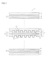
- the main cell unit 5 and the separators 10 composes a unit cell U, and a plurality of the unit cells U are stacked while individually placing a cooling water flowing substrate 11 (composed of a conductive material such as graphite) in between, to thereby configure a fuel cell stack 1.
- the unit cells U are stacked in, for example, the number of 50 to 400 or around, and respectively on both ends of the stack, there are disposed, as viewed from the side in contact with the unit cell U, a conductive sheet 9, a current collector plate 8, an insulating sheet 7, and a tightening plate 6, to thereby configure a fuel cell stack 1.
- the current collector plate 8 and a plurality of separators 10 are connected in series, so as to collect current from a plurality of main cell units 5.
- FIG. 1 shows the individual components, including the conductive sheet 9, current collector plate 8, insulating sheet 7 and tightening plate 6, are illustrated as being departed from each other, but these components in practice are tightened with each other using bolts, for example.
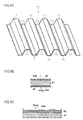
- FIG. 2A and FIG 2B show the outlines of the separator 10.
- the separators 10 are shaped in a plate form, have a regular rough formed on the main surfaces thereof, and are disposed so as to make the end sides of the projected portions 14 of the separators 10 contact with the electrodes 2, 4.
- the recessed portions of each separator 10 serve as gas a flow path 21 (see also FIG. 1 ) through which a fuel gas or an oxidizer gas is supplied to the electrodes 2, 4.
- the gas flow path 21 has openings formed on both ends thereof, which serve as a reaction gas inlet port 22 and a reaction gas outlet port 23, respectively.
- the separators 10 are stacked so that the reaction gas inlet ports 22 and reaction gas outlet ports 23 formed on the individual separators 10 are aligned at the same positions.
- the separator 10 comprises a metal base 13 and an Au film 12 formed on the main surface thereof, wherein the Au film 12 is formed not only on top surfaces 14a of the projected portions 14, but also on the side faces 15a and bottoms 15b of the recessed portions 15 (non-contact regions) which are not planned to contact with the electrodes 2, 4. Thickness of the Au film 12 is adjusted to 1 to 500 nm.
- the Au film 12 is an Au-plated film 12.
- FIG. 9A shows the separator 10 which is another mode of the polymer electrolyte fuel cell material described here.
- the separator 10 has, as shown in the drawing, a plurality of ridges 12, 16 and a plurality of grooves 14, 18 in parallel with each other on the top surface and back surface in an inside-out relation.
- the separator 10 comprises a plate material 41 of approximately 0.2 mm thick composed of an austenitic stainless steel, and cover films 44a, 44b of 1 to 40 nm thick composed of Au (noble metal) formed so as to cover the top surface 42 and back surface 43 thereof.
- the thickness of the cover films 44a, 44b is specified within the above-described range because the thickness smaller than 1 nm degrades the corrosion resistance, and the thickness exceeding 40 nm increases the cost.
- the separator 10 is exposed, for a long duration of time, to a sulfuric-acid and steamy environment of approximately 80°C or above under power generation during which the fuel gas (hydrogen, methanol) or oxidizer gas (air, oxygen) flows through the grooves 14, 18, so as to cause the oxidation and reduction reactions through the polymer electrolyte film disposed in adjacent thereto.
- the separator 10 can exhibit an excellent corrosion resistance in such environment for a long duration of time.
- FIG. 10A shows a section of the plate material 41 of 0.2 mm thick, composed of the austenitic stainless steel (SUS316L; C ⁇ 0.08 wt%, Si ⁇ 1.00 wt%, Mn ⁇ 2.00 wt%, P ⁇ 0.045 wt%, S ⁇ 0.030 wt%, Ni: 12.00 to 15.00 wt%, Cr: 16.00 to 18.00 wt%, Mo: 2.00 to 3.00 wt%, and the balance of Fe), which corresponds with the Fe-base alloy described here.
- the austenitic stainless steel SUS316L; C ⁇ 0.08 wt%, Si ⁇ 1.00 wt%, Mn ⁇ 2.00 wt%, P ⁇ 0.045 wt%, S ⁇ 0.030 wt%, Ni: 12.00 to 15.00 wt%, Cr: 16.00 to 18.00 wt%, Mo: 2.00 to 3.00 wt%, and the balance of Fe), which corresponds
- the top surface 42 and back surface 43 of the plate material 41 are subjected to a publicly-known Au electroplating or Au electroless plating (coverage step). This results in formation of the cover films 44a, 44b of Au (noble metal) of approximately 40 nm thick, respectively on the top surface 42 and back surface 43 of the plate material 41, to thereby obtain a stacked plate 45, as shown in FIG. 10B .
- the surface 44ax of the Au film 44a has a regular rough conforming to the regular rough of the surface 42 of the plate material 41 in the stacked plate 45, with an enhanced profile.
- the regular rough on the surface 42 is produced due to transfer of regular roughs on the circumferential surface of the rolling roll, and loss of the metal component caused by surface treatment such as acid cleaning or by heat treatment such as annealing.
- the Au cover film 44a conforms to the regular rough of the surface 42 but is thicker on the projected portions and thinner on the recessed portions, so that the surface 44ax thereof finally has a more emphasized profile. It is to be noted that also the Au cover film 44b on the back surface 43 of the plate material 41 has a similar regular rough on the surface 44bx thereof.
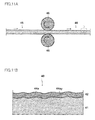
- the stacked plate 45 covered with the Au cover films 44a, 44b on the top and back surfaces 42, 43 thereof is subjected to cold rolling (rolling step) by allowing it to pass between a pair of rolls 46, 46 as shown in FIG. 11A .
- the draft herein is typically set to 1% or above, and more specifically 10%.
- the surface roughness of the circumferential surface of the rolls 46, 46 is 1.5 ⁇ m or less expressed in R max .
- R max This produces the elementary plate 48 slightly thinned as shown on the right hand side of FIG. 11A .
- the Au cover films 44a, 44b which are relatively soft, are preferentially compressed. Average thickness of the cover films 44a, 44b will be reduced nearly in proportion to the draft of the rolling.
- FIG. 11B which is an enlargement of portion B surrounded by a dashed line in FIG. 11A
- the surface 42 of the plate material 41 is slightly compressed, so that also the regular rough thereof is smoothened to a correspondent degree.
- the surface 44ay of the Au cover film 44a newly produced by the rolling is compressed and smoothened to a considerable degree during the rolling. This is consequently successful in suppressing the surface roughness as expressed in R max of the surface 44ay to as small as 1.5 ⁇ m or less.
- the plate material 41 may be composed of any stainless steels other than those described in the above, or other Fe-base alloy, Ni-base alloy, Ti and Ti alloy.
- the noble metal is not limited to Au, but also may be Ag, Pt, Pd, Rh or Ir, or alloys mainly composed of any of these elements.
- it is also allowable to fabricate the elementary plate 48, similarly to the second fabrication method , by forming the cover films 44a, 44b of a noble metal such as Au on the top surface 42 and back surface 43 of the plate material 41 after the smoothening step based on electrolytic polishing or rolling using the rolls having a surface roughness as expressed in R max of 1.5 ⁇ m or less.
- the Au films 44a, 44b were then formed on the top surfaces 42 and back surfaces 43 of eight plate materials 41 to a thickness of 20 nm under the same plating conditions, to thereby obtain eight stacked plates 5.
- Example 5 Of six plate materials not being subjected to the smoothening process, the five subjected to rolling were named Examples 1 to 4 and Comparative Example 1.
- Example 5 The one subjected to both of the smoothening and rolling processes was named Example 5, and the one subjected to the smoothening process but not to the rolling process was named Example 6.
- Example 6 the residual one subjected to neither of the smoothening process nor the rolling process was named Comparative Example 2.
- each of the plates of the individual examples was kept as being dipped in 0.4 liter (L) of a 0.1 % sulfuric acid solution (pH2) boiled under reflux for 168 hours (7 days), and metal ions eluted into the solution was analyzed by atomic absorption spectrometry, and amount thereof was expressed in weight per 0.4 liter (L) of the solution. Also these results were listed by the individual examples in Table 6. Table 6.
- Comparative Example 1 showed both of amounts of Fe ion elution and Ni ion elution slightly exceeding the specified ranges due to a surface roughness (R max ) after rolling of as large as 1.8 ⁇ m, despite a surface roughness (R max ) before Au plating of 2.2 ⁇ m.
- Comparative Example 2 which was subjected only to the Au plating but not to rolling or smoothing was found to be extremely increased both in the amounts of Fe ion elution and Ni ion elution.
- Example 5 which was preliminarily subjected to the smoothening step prior to the Au plating was found to have a surface roughness (R max ) after Au plating of as small as 1.2 ⁇ m, and to have a surface roughness (R max ) after rolling of again as small as 0.2 ⁇ m, and was smallest of all examples in the amounts of Fe ion elution and Ni ion elution.
- Example 6 which was preliminarily smoothened by electrolytic polishing so as to reduce the surface roughness (R max ) to as small as 0.8 ⁇ m, was found to fall in the above-described specified ranges even without the rolling.
- the above-described cell material is also successful in exhibiting an excellent corrosion resistance in a more reliable manner, if it is exposed for a long time, in a form of a separator for example, to an extremely corrosive environment.
- the method of manufacturing the cell material it is made possible to surely smoothen the cover film of a noble metal, which is formed conforming to the micro-irregularity on the surface of the plate material, so as to reduce the surface roughness as expressed in R max to as small as 1.5 ⁇ m or less.
Landscapes
- Chemical & Material Sciences (AREA)
- Chemical Kinetics & Catalysis (AREA)
- Manufacturing & Machinery (AREA)
- Sustainable Development (AREA)
- Sustainable Energy (AREA)
- Engineering & Computer Science (AREA)
- Life Sciences & Earth Sciences (AREA)
- Electrochemistry (AREA)
- General Chemical & Material Sciences (AREA)
- Composite Materials (AREA)
- Fuel Cell (AREA)
- Electroplating Methods And Accessories (AREA)
- Physical Vapour Deposition (AREA)
Claims (1)
- Verfahren zur Herstellung eines Polymerelektrolyt-Brennstoffzellenmaterials, umfassend:- einen Glättungsschritt, in welchem ein Plattenmaterial (41) aus einer Fe-Basis-Legierung, Ni-Basis-Legierung, Ti oder Ti-Basis-Legierung geglättet wird, um eine Oberflächen(42,43)-Rauheit, die durch eine Rmax von 1,5 µm oder weniger ausgedrückt ist, zu erzielen, und zwar durch Walzen mit einer Dickenreduktion von 5 bis 50 % unter Verwendung eines Walzenpaars (46, 46), das eine Oberflächenrauheit von 1,5 µm oder weniger, die in Rmax ausgedrückt ist, aufweist; und- einen Abdeckungsschritt, in welchem eine Deckfolie (44a, 44b) aus einem Edelmetall gebildet wird, um wenigstens eine der Oberflächen obere Oberfläche (42) oder rückwärtige Oberfläche (43) des Plattenmaterials (41) abzudecken.
Applications Claiming Priority (5)
| Application Number | Priority Date | Filing Date | Title |
|---|---|---|---|
| JP2002239723 | 2002-08-20 | ||
| JP2002257259 | 2002-09-03 | ||
| JP2002312226 | 2002-10-28 | ||
| JP2002380581 | 2002-12-27 | ||
| EP03792704.3A EP1557895B1 (de) | 2002-08-20 | 2003-08-19 | Metallische komponente für eine brennstoffzelle und verfahren zu deren herstellung sowie eine brennstoffzelle welche dieselbige enthält |
Related Parent Applications (3)
| Application Number | Title | Priority Date | Filing Date |
|---|---|---|---|
| EP03792704.3A Division-Into EP1557895B1 (de) | 2002-08-20 | 2003-08-19 | Metallische komponente für eine brennstoffzelle und verfahren zu deren herstellung sowie eine brennstoffzelle welche dieselbige enthält |
| EP03792704.3A Division EP1557895B1 (de) | 2002-08-20 | 2003-08-19 | Metallische komponente für eine brennstoffzelle und verfahren zu deren herstellung sowie eine brennstoffzelle welche dieselbige enthält |
| EP03792704.3 Division | 2003-08-19 |
Publications (2)
| Publication Number | Publication Date |
|---|---|
| EP2339680A1 EP2339680A1 (de) | 2011-06-29 |
| EP2339680B1 true EP2339680B1 (de) | 2015-03-25 |
Family
ID=31950734
Family Applications (3)
| Application Number | Title | Priority Date | Filing Date |
|---|---|---|---|
| EP11154444.1A Expired - Lifetime EP2339680B1 (de) | 2002-08-20 | 2003-08-19 | Verfahren zur Herstellung eines Materials für eine feste Polymerbrennstoffzelle |
| EP03792704.3A Expired - Lifetime EP1557895B1 (de) | 2002-08-20 | 2003-08-19 | Metallische komponente für eine brennstoffzelle und verfahren zu deren herstellung sowie eine brennstoffzelle welche dieselbige enthält |
| EP11154448A Ceased EP2339679A1 (de) | 2002-08-20 | 2003-08-19 | Korrosionsbeständige leitfähige Elemente und deren Herstellungsverfahren sowie Brennstoffzelle |
Family Applications After (2)
| Application Number | Title | Priority Date | Filing Date |
|---|---|---|---|
| EP03792704.3A Expired - Lifetime EP1557895B1 (de) | 2002-08-20 | 2003-08-19 | Metallische komponente für eine brennstoffzelle und verfahren zu deren herstellung sowie eine brennstoffzelle welche dieselbige enthält |
| EP11154448A Ceased EP2339679A1 (de) | 2002-08-20 | 2003-08-19 | Korrosionsbeständige leitfähige Elemente und deren Herstellungsverfahren sowie Brennstoffzelle |
Country Status (5)
| Country | Link |
|---|---|
| US (2) | US7597987B2 (de) |
| EP (3) | EP2339680B1 (de) |
| JP (3) | JP4802710B2 (de) |
| CA (3) | CA2729338C (de) |
| WO (1) | WO2004019437A1 (de) |
Families Citing this family (29)
| Publication number | Priority date | Publication date | Assignee | Title |
|---|---|---|---|---|
| JP5403642B2 (ja) * | 2003-11-07 | 2014-01-29 | 大同特殊鋼株式会社 | 耐食性導電部材 |
| JP4792213B2 (ja) * | 2004-07-29 | 2011-10-12 | 東海ゴム工業株式会社 | 固体高分子型燃料電池用セパレータおよびそれを用いた固体高分子型燃料電池用セル |
| US7632592B2 (en) * | 2004-11-01 | 2009-12-15 | Gm Global Technology Operations, Inc. | Method of fabricating corrosion-resistant bipolar plate |
| JP4578280B2 (ja) * | 2005-03-08 | 2010-11-10 | 日新製鋼株式会社 | 自動車給油系部材用オーステナイト系ステンレス鋼 |
| JP2006278172A (ja) * | 2005-03-29 | 2006-10-12 | Nikko Kinzoku Kk | 燃料電池のセパレータ用材料 |
| JP4859189B2 (ja) * | 2005-11-29 | 2012-01-25 | Jx日鉱日石金属株式会社 | 貴金属めっきを施したチタン又はチタン合金材料 |
| JP5082275B2 (ja) * | 2006-04-03 | 2012-11-28 | 大日本印刷株式会社 | 燃料電池用のセパレータおよびその製造方法 |
| JP5205814B2 (ja) * | 2006-08-09 | 2013-06-05 | 大同特殊鋼株式会社 | 燃料電池用金属セパレータおよびこれを用いた燃料電池 |
| JP2008047381A (ja) * | 2006-08-14 | 2008-02-28 | Toyo Seikan Kaisha Ltd | 燃料電池用ステンレス部材 |
| JP5286551B2 (ja) * | 2006-08-14 | 2013-09-11 | 東洋製罐株式会社 | 燃料電池用コイルスプリング |
| JP4762104B2 (ja) * | 2006-10-11 | 2011-08-31 | 日新製鋼株式会社 | オーステナイト鋼 |
| JP5167627B2 (ja) * | 2006-11-15 | 2013-03-21 | 日産自動車株式会社 | 燃料電池 |
| ES2674072T3 (es) * | 2007-02-06 | 2018-06-27 | Nuvera Fuel Cells, LLC | Unidad bipolar para pila de combustible provista de colectores de corriente porosos |
| US20100330389A1 (en) * | 2009-06-25 | 2010-12-30 | Ford Motor Company | Skin pass for cladding thin metal sheets |
| JP5455204B2 (ja) * | 2009-08-05 | 2014-03-26 | Jx日鉱日石金属株式会社 | 燃料電池用セパレータ材料、それを用いた燃料電池スタック |
| JP5419816B2 (ja) * | 2010-07-09 | 2014-02-19 | Jx日鉱日石金属株式会社 | 燃料電池用セパレータ材料、それを用いた燃料電池用セパレータ及び燃料電池スタック |
| US8232026B2 (en) | 2010-10-14 | 2012-07-31 | Ford Global Technologies, Llc | Bipolar plates for electrochemical cells |
| JP5590008B2 (ja) * | 2011-11-14 | 2014-09-17 | 日本軽金属株式会社 | 燃料電池用集電板及びその製造方法 |
| US8778558B2 (en) * | 2012-05-18 | 2014-07-15 | GM Global Technology Operations LLC | Methods for making a thermoformed subgasket and products thereof |
| WO2014010663A1 (ja) * | 2012-07-13 | 2014-01-16 | 東洋鋼鈑株式会社 | 燃料電池用セパレータ、燃料電池セル、燃料電池スタック、および燃料電池用セパレータの製造方法 |
| JP6111058B2 (ja) * | 2012-12-07 | 2017-04-05 | 東洋鋼鈑株式会社 | 燃料電池用セパレータ、燃料電池セル、燃料電池スタック、および燃料電池用セパレータの製造方法 |
| KR101982620B1 (ko) * | 2013-02-26 | 2019-05-27 | 타츠타 전선 주식회사 | 플렉시블 프린트 배선판용 보강 부재, 플렉시블 프린트 배선판, 및 차폐 프린트 배선판 |
| WO2014199526A1 (ja) * | 2013-06-13 | 2014-12-18 | 東洋鋼鈑株式会社 | 金めっき被覆ステンレス材、および金めっき被覆ステンレス材の製造方法 |
| JP6495172B2 (ja) * | 2013-09-20 | 2019-04-03 | 東洋鋼鈑株式会社 | 金属めっき被覆ステンレス材、および金属めっき被覆ステンレス材の製造方法 |
| WO2019082591A1 (ja) * | 2017-10-25 | 2019-05-02 | Jfeスチール株式会社 | 燃料電池のセパレータ用のステンレス鋼板の製造方法 |
| JP7484760B2 (ja) * | 2021-02-10 | 2024-05-16 | トヨタ自動車株式会社 | セパレータの製造方法 |
| CN115172793A (zh) * | 2021-04-07 | 2022-10-11 | 罗伯特·博世有限公司 | 燃料电池的双极板及其制造方法、燃料电池 |
| CN116024530A (zh) * | 2023-01-09 | 2023-04-28 | 西安热工研究院有限公司 | 一种改性铝化物涂层及其制备方法 |
| CN116005079A (zh) * | 2023-01-09 | 2023-04-25 | 西安热工研究院有限公司 | 一种高导电性能的抗高温氧化涂层及其制备方法 |
Family Cites Families (40)
| Publication number | Priority date | Publication date | Assignee | Title |
|---|---|---|---|---|
| JPS597359B2 (ja) * | 1977-12-30 | 1984-02-17 | セイコーエプソン株式会社 | メツキ方法 |
| JPS5735669A (en) | 1980-08-08 | 1982-02-26 | Daido Steel Co Ltd | Free cutting austenite stainless steel |
| JPS57174493A (en) * | 1981-04-20 | 1982-10-27 | Arakawa Kako Kk | Noble metal plating method of austenitic stainless steel |
| JPS6047913B2 (ja) * | 1981-11-18 | 1985-10-24 | 正己 小林 | ステンレス鋼に直接金メツキを施す方法 |
| TW290592B (de) * | 1993-07-08 | 1996-11-11 | Asahi Seiko Co Ltd | |
| JPH07114928A (ja) * | 1993-10-14 | 1995-05-02 | Mitsubishi Materials Corp | すぐれた高温強度を有する溶融炭酸塩燃料電池のセパレータ材 |
| RU2117065C1 (ru) * | 1995-04-21 | 1998-08-10 | Ниппон Стил Корпорейшн | Высокопрочный высокопластичный титановый сплав и способ его изготовления |
| DE19532791A1 (de) * | 1995-09-06 | 1996-12-12 | Mtu Friedrichshafen Gmbh | Kathodenstromkollektor für eine Brennstoffzelle |
| JP3540491B2 (ja) * | 1996-03-07 | 2004-07-07 | 政廣 渡辺 | 燃料電池及び電解セル並びにその冷却・除湿方法 |
| US5851689A (en) * | 1997-01-23 | 1998-12-22 | Bechtel Corporation | Method for operating a fuel cell assembly |
| JP3854682B2 (ja) | 1997-02-13 | 2006-12-06 | アイシン高丘株式会社 | 燃料電池用セパレータ |
| FR2759709B1 (fr) * | 1997-02-18 | 1999-03-19 | Ugine Savoie Sa | Acier inoxydable pour l'elaboration de fil trefile notamment de fil de renfort de pneumatique et procede de realisation dudit fil |
| DE19805674C1 (de) * | 1998-02-12 | 1999-09-02 | Forschungszentrum Juelich Gmbh | Mit Edelmetall lokal belegte bipolare Platte und Verfahren zu deren Herstellung |
| JPH11297338A (ja) | 1998-04-10 | 1999-10-29 | Nisshinbo Ind Inc | 固体高分子型燃料電地用セパレータ及びその製造方法 |
| JPH11329460A (ja) * | 1998-05-08 | 1999-11-30 | Aisin Takaoka Ltd | 燃料電池のセパレータの製造方法 |
| US6410178B1 (en) * | 1998-05-08 | 2002-06-25 | Aisin Takaoka Co., Ltd. | Separator of fuel cell and method for producing same |
| JP3858456B2 (ja) | 1998-06-18 | 2006-12-13 | 住友金属工業株式会社 | 耐硫酸露点腐食性に優れたオーステナイト系ステンレス鋼及びその製造方法 |
| JP2000021418A (ja) * | 1998-06-30 | 2000-01-21 | Matsushita Electric Ind Co Ltd | 固体高分子電解質型燃料電池 |
| JP4276325B2 (ja) | 1999-03-10 | 2009-06-10 | 新日本製鐵株式会社 | 固体高分子型燃料電池用ステンレス鋼 |
| US6251253B1 (en) * | 1999-03-19 | 2001-06-26 | Technic, Inc. | Metal alloy sulfate electroplating baths |
| JP2000328200A (ja) | 1999-05-13 | 2000-11-28 | Sumitomo Metal Ind Ltd | 通電電気部品用オーステナイト系ステンレス鋼および燃料電池 |
| JP3397169B2 (ja) | 1999-04-22 | 2003-04-14 | 住友金属工業株式会社 | 固体高分子型燃料電池セパレータ用オーステナイト系ステンレス鋼および固体高分子型燃料電池 |
| KR100361548B1 (ko) * | 1999-04-19 | 2002-11-21 | 스미토모 긴조쿠 고교 가부시키가이샤 | 고체고분자형 연료전지용 스텐레스 강재 |
| JP2000323151A (ja) | 1999-05-12 | 2000-11-24 | Matsushita Electric Ind Co Ltd | 燃料電池およびその製造法 |
| JP2001068129A (ja) | 1999-08-30 | 2001-03-16 | Aisin Seiki Co Ltd | 燃料電池用セパレータおよびその製造方法および燃料電池 |
| JP4656683B2 (ja) * | 1999-09-02 | 2011-03-23 | パナソニック株式会社 | 高分子電解質型燃料電池 |
| JP4529205B2 (ja) * | 1999-11-30 | 2010-08-25 | 株式会社豊田中央研究所 | 燃料電池用セパレータおよびこれを備えた燃料電池 |
| US6372376B1 (en) * | 1999-12-07 | 2002-04-16 | General Motors Corporation | Corrosion resistant PEM fuel cell |
| JP2001236967A (ja) * | 2000-02-25 | 2001-08-31 | Sumitomo Electric Ind Ltd | 固体高分子電解質型燃料電池用セパレータ |
| JP4604302B2 (ja) | 2000-02-28 | 2011-01-05 | パナソニック株式会社 | 高分子電解質型燃料電池 |
| FR2805829B1 (fr) * | 2000-03-03 | 2002-07-19 | Ugine Savoie Imphy | Acier inoxydable austenitique a haute usinabilite, resulfure, et comportant une resistance a la corrosion amelioree |
| JP4366872B2 (ja) * | 2000-03-13 | 2009-11-18 | トヨタ自動車株式会社 | 燃料電池用ガスセパレータおよび該燃料電池用セパレータの製造方法並びに燃料電池 |
| JP2001297777A (ja) * | 2000-04-13 | 2001-10-26 | Matsushita Electric Ind Co Ltd | 高分子電解質型燃料電池 |
| JP2001345109A (ja) * | 2000-05-31 | 2001-12-14 | Aisin Takaoka Ltd | 燃料電池用セパレータ |
| JP2002075399A (ja) * | 2000-08-30 | 2002-03-15 | Hitachi Ltd | 固体高分子電解質型燃料電池用セパレータ |
| JP2002151097A (ja) * | 2000-11-15 | 2002-05-24 | Suncall Corp | 燃料電池用セパレーター |
| JP3958929B2 (ja) | 2000-12-21 | 2007-08-15 | 新日本製鐵株式会社 | 固体高分子型燃料電池用セパレータ製造装置 |
| JP2002206148A (ja) * | 2001-01-09 | 2002-07-26 | Nisshin Steel Co Ltd | 加工割れ感受性が低いオーステナイト系ステンレス鋼板およびその製造方法 |
| CA2373344C (en) * | 2001-02-28 | 2012-03-20 | Daido Tokushuko Kabushiki Kaisha | Corrosion-resistant metallic member, metallic separator for fuel cell comprising the same, and process for production thereof |
| JP3991701B2 (ja) | 2002-02-08 | 2007-10-17 | 大同特殊鋼株式会社 | 燃料電池用金属セパレータ及びその製造方法 |
-
2003
- 2003-08-19 JP JP2005501228A patent/JP4802710B2/ja not_active Expired - Fee Related
- 2003-08-19 CA CA2729338A patent/CA2729338C/en not_active Expired - Fee Related
- 2003-08-19 EP EP11154444.1A patent/EP2339680B1/de not_active Expired - Lifetime
- 2003-08-19 US US10/525,234 patent/US7597987B2/en not_active Expired - Fee Related
- 2003-08-19 EP EP03792704.3A patent/EP1557895B1/de not_active Expired - Lifetime
- 2003-08-19 WO PCT/JP2003/010428 patent/WO2004019437A1/ja not_active Ceased
- 2003-08-19 CA CA2729418A patent/CA2729418C/en not_active Expired - Fee Related
- 2003-08-19 EP EP11154448A patent/EP2339679A1/de not_active Ceased
- 2003-08-19 CA CA2496339A patent/CA2496339C/en not_active Expired - Fee Related
-
2009
- 2009-10-05 US US12/573,756 patent/US8133632B2/en not_active Expired - Fee Related
-
2010
- 2010-04-13 JP JP2010092644A patent/JP2010236091A/ja active Pending
- 2010-04-13 JP JP2010092610A patent/JP5152537B2/ja not_active Expired - Fee Related
Also Published As
| Publication number | Publication date |
|---|---|
| JPWO2004019437A1 (ja) | 2005-12-15 |
| EP1557895B1 (de) | 2014-04-30 |
| US20060159971A1 (en) | 2006-07-20 |
| CA2729418A1 (en) | 2004-03-04 |
| EP1557895A4 (de) | 2010-05-19 |
| CA2729418C (en) | 2014-08-19 |
| JP2010236091A (ja) | 2010-10-21 |
| EP2339680A1 (de) | 2011-06-29 |
| CA2729338A1 (en) | 2004-03-04 |
| US8133632B2 (en) | 2012-03-13 |
| CA2496339A1 (en) | 2004-03-04 |
| CA2729338C (en) | 2012-04-17 |
| WO2004019437A1 (ja) | 2004-03-04 |
| EP1557895A1 (de) | 2005-07-27 |
| CA2496339C (en) | 2012-03-27 |
| JP4802710B2 (ja) | 2011-10-26 |
| JP2010177212A (ja) | 2010-08-12 |
| JP5152537B2 (ja) | 2013-02-27 |
| US7597987B2 (en) | 2009-10-06 |
| US20100035115A1 (en) | 2010-02-11 |
| EP2339679A1 (de) | 2011-06-29 |
Similar Documents
| Publication | Publication Date | Title |
|---|---|---|
| EP2339680A1 (de) | Material für feste Polymerbrennstoffzelle und deren Herstellungsverfahren sowie Materialelement für Brennstoffzelle und Brennstoffzelle mit dem Material für eine feste Polymerbrennstoffzelle | |
| JP5205814B2 (ja) | 燃料電池用金属セパレータおよびこれを用いた燃料電池 | |
| EP1990855B1 (de) | Separator für festpolymerbrennstoffzelle und verfahren zu dessen herstellung | |
| US8173328B2 (en) | Interconnects for solid oxide fuel cells and ferritic stainless steels adapted for use with solid oxide fuel cells | |
| DE69906860T2 (de) | Separatorplatte für Brennstoffzellen, Verfahren zu deren Herstellung und diese enthaltende Brennstoffzelle | |
| EP1726674B1 (de) | Metallmaterial für stromführendes element, separator für brennstoffzelle damit und brennstoffzelle damit | |
| US7842434B2 (en) | Interconnects for solid oxide fuel cells and ferritic stainless steels adapted for use with solid oxide fuel cells | |
| US20040106029A1 (en) | Corrosion resistant coated fuel cell bipolar plate with filled-in fine scale porosities | |
| EP2849271A1 (de) | Separatoren für Festoxid-Brennstoffzellen und ferritische Edelstähle zu deren Verwendung für Festoxid-Brennstoffzellen | |
| US8231990B2 (en) | Alloy film for a metal separator for a fuel cell, a manufacturing method thereof and a target material for sputtering, as well as a metal separator, and a fuel cell | |
| EP2031687B1 (de) | Reintitan- oder titanlegierungsabscheider für festpolymerbrennstoffzelle und verfahren zu seiner herstellung | |
| EP1906477A1 (de) | Trennglied für eine festpolymerelektrolyt-brennstoffzelle aus rostfreiem stahl, titan oder titanlegierung, herstellungsprozess dafür und verfahren zur bewertung einer verzerrung und verdrehung des trennglieds | |
| US8158057B2 (en) | Interconnects for solid oxide fuel cells and ferritic stainless steels adapted for use with solid oxide fuel cells | |
| EP3181728B1 (de) | Metallmaterial und stromführendes bauteil mit diesem metallmaterial | |
| US20050095489A1 (en) | Metallic separator for fuel cell and manufacturing method therefor | |
| US20030064273A1 (en) | Separator for fuel cell and method for producing the same | |
| EP1492187B1 (de) | Korrosionsbeständiger metall-separator für eine brennstoffzelle | |
| HK1079906A (en) | Metal member for fuel cell and its manufacturing method, austenitic stainless steel for solid polymer fuel cell and metal member for fuel cell using same, material for solid polymer fuel cell and its manufacturing method, corrosion-resistance conductive member and its manufacturing method, and fuel cell | |
| US20050130013A1 (en) | Metal separator for fuel cell and method for producing the same | |
| EP1908854B1 (de) | Legierungen auf Nickelbasis |
Legal Events
| Date | Code | Title | Description |
|---|---|---|---|
| PUAI | Public reference made under article 153(3) epc to a published international application that has entered the european phase |
Free format text: ORIGINAL CODE: 0009012 |
|
| AC | Divisional application: reference to earlier application |
Ref document number: 1557895 Country of ref document: EP Kind code of ref document: P |
|
| AK | Designated contracting states |
Kind code of ref document: A1 Designated state(s): DE FR GB IT |
|
| RIN1 | Information on inventor provided before grant (corrected) |
Inventor name: URA, MIKIO Inventor name: SHINKAWA, MASAKI Inventor name: YAGI, SHINICHI Inventor name: TAKAGI, SHINOBU Inventor name: KANETA, YASUSHI Inventor name: HISADA, TATSUO |
|
| 17P | Request for examination filed |
Effective date: 20111222 |
|
| RIN1 | Information on inventor provided before grant (corrected) |
Inventor name: HISADA, TATSUO Inventor name: KANETA, YASUSHI Inventor name: YAGI, SHINICHI Inventor name: TAKAGI, SHINOBU Inventor name: SHINKAWA, MASAKI Inventor name: URA, MIKIO |
|
| 17Q | First examination report despatched |
Effective date: 20120327 |
|
| R17C | First examination report despatched (corrected) |
Effective date: 20120330 |
|
| GRAP | Despatch of communication of intention to grant a patent |
Free format text: ORIGINAL CODE: EPIDOSNIGR1 |
|
| RIC1 | Information provided on ipc code assigned before grant |
Ipc: H01M 8/02 20060101AFI20140929BHEP Ipc: H01M 8/10 20060101ALN20140929BHEP |
|
| INTG | Intention to grant announced |
Effective date: 20141015 |
|
| RIN1 | Information on inventor provided before grant (corrected) |
Inventor name: TAKAGI, SHINOBU Inventor name: YAGI, SHINICHI Inventor name: KANETA, YASUSHI Inventor name: URA, MIKIO Inventor name: HISADA, TATSUO Inventor name: SHINKAWA, MASAKI |
|
| GRAS | Grant fee paid |
Free format text: ORIGINAL CODE: EPIDOSNIGR3 |
|
| GRAA | (expected) grant |
Free format text: ORIGINAL CODE: 0009210 |
|
| AC | Divisional application: reference to earlier application |
Ref document number: 1557895 Country of ref document: EP Kind code of ref document: P |
|
| AK | Designated contracting states |
Kind code of ref document: B1 Designated state(s): DE FR GB IT |
|
| REG | Reference to a national code |
Ref country code: GB Ref legal event code: FG4D |
|
| REG | Reference to a national code |
Ref country code: DE Ref legal event code: R096 Ref document number: 60347449 Country of ref document: DE Effective date: 20150430 |
|
| REG | Reference to a national code |
Ref country code: FR Ref legal event code: PLFP Year of fee payment: 13 |
|
| PGFP | Annual fee paid to national office [announced via postgrant information from national office to epo] |
Ref country code: FR Payment date: 20150630 Year of fee payment: 13 |
|
| REG | Reference to a national code |
Ref country code: DE Ref legal event code: R097 Ref document number: 60347449 Country of ref document: DE |
|
| PLBE | No opposition filed within time limit |
Free format text: ORIGINAL CODE: 0009261 |
|
| STAA | Information on the status of an ep patent application or granted ep patent |
Free format text: STATUS: NO OPPOSITION FILED WITHIN TIME LIMIT |
|
| 26N | No opposition filed |
Effective date: 20160105 |
|
| PG25 | Lapsed in a contracting state [announced via postgrant information from national office to epo] |
Ref country code: IT Free format text: LAPSE BECAUSE OF FAILURE TO SUBMIT A TRANSLATION OF THE DESCRIPTION OR TO PAY THE FEE WITHIN THE PRESCRIBED TIME-LIMIT Effective date: 20150325 |
|
| PGFP | Annual fee paid to national office [announced via postgrant information from national office to epo] |
Ref country code: GB Payment date: 20160817 Year of fee payment: 14 Ref country code: DE Payment date: 20160816 Year of fee payment: 14 |
|
| REG | Reference to a national code |
Ref country code: FR Ref legal event code: ST Effective date: 20170428 |
|
| PG25 | Lapsed in a contracting state [announced via postgrant information from national office to epo] |
Ref country code: FR Free format text: LAPSE BECAUSE OF NON-PAYMENT OF DUE FEES Effective date: 20160831 |
|
| REG | Reference to a national code |
Ref country code: DE Ref legal event code: R119 Ref document number: 60347449 Country of ref document: DE |
|
| GBPC | Gb: european patent ceased through non-payment of renewal fee |
Effective date: 20170819 |
|
| PG25 | Lapsed in a contracting state [announced via postgrant information from national office to epo] |
Ref country code: DE Free format text: LAPSE BECAUSE OF NON-PAYMENT OF DUE FEES Effective date: 20180301 Ref country code: GB Free format text: LAPSE BECAUSE OF NON-PAYMENT OF DUE FEES Effective date: 20170819 |