EP2292949B1 - Steuervorrichtung und Steuerverfahren für Automatikgetriebe - Google Patents
Steuervorrichtung und Steuerverfahren für Automatikgetriebe Download PDFInfo
- Publication number
- EP2292949B1 EP2292949B1 EP10008060.5A EP10008060A EP2292949B1 EP 2292949 B1 EP2292949 B1 EP 2292949B1 EP 10008060 A EP10008060 A EP 10008060A EP 2292949 B1 EP2292949 B1 EP 2292949B1
- Authority
- EP
- European Patent Office
- Prior art keywords
- condition
- vehicle speed
- friction element
- engaged
- predetermined
- Prior art date
- Legal status (The legal status is an assumption and is not a legal conclusion. Google has not performed a legal analysis and makes no representation as to the accuracy of the status listed.)
- Not-in-force
Links
- 230000005540 biological transmission Effects 0.000 title claims description 35
- 238000000034 method Methods 0.000 title claims description 4
- 230000001133 acceleration Effects 0.000 claims description 33
- 238000012545 processing Methods 0.000 description 35
- 230000001105 regulatory effect Effects 0.000 description 30
- 239000000446 fuel Substances 0.000 description 14
- 101100045633 Arabidopsis thaliana TCX3 gene Proteins 0.000 description 11
- 101150037491 SOL1 gene Proteins 0.000 description 11
- 230000006872 improvement Effects 0.000 description 11
- 101100096184 Alternaria solani sol5 gene Proteins 0.000 description 10
- 101100168642 Arabidopsis thaliana CRN gene Proteins 0.000 description 10
- 101100045632 Arabidopsis thaliana TCX2 gene Proteins 0.000 description 10
- 101150103732 sol2 gene Proteins 0.000 description 10
- 101100096185 Alternaria solani sol6 gene Proteins 0.000 description 9
- 101150032095 SOL3 gene Proteins 0.000 description 8
- 101150090449 sol4 gene Proteins 0.000 description 8
- 230000008878 coupling Effects 0.000 description 3
- 238000010168 coupling process Methods 0.000 description 3
- 238000005859 coupling reaction Methods 0.000 description 3
- 239000012530 fluid Substances 0.000 description 3
- 238000004891 communication Methods 0.000 description 2
- 230000001276 controlling effect Effects 0.000 description 2
- 239000003112 inhibitor Substances 0.000 description 2
- 230000007246 mechanism Effects 0.000 description 2
- 230000004048 modification Effects 0.000 description 2
- 238000012986 modification Methods 0.000 description 2
- 230000009467 reduction Effects 0.000 description 2
- 230000035807 sensation Effects 0.000 description 2
- 230000003068 static effect Effects 0.000 description 2
- 230000008859 change Effects 0.000 description 1
- 230000000052 comparative effect Effects 0.000 description 1
- 238000007796 conventional method Methods 0.000 description 1
- 230000001419 dependent effect Effects 0.000 description 1
- 230000000881 depressing effect Effects 0.000 description 1
- 230000000694 effects Effects 0.000 description 1
- 238000002347 injection Methods 0.000 description 1
- 239000007924 injection Substances 0.000 description 1
- 238000012423 maintenance Methods 0.000 description 1
- 230000002265 prevention Effects 0.000 description 1
- 230000001629 suppression Effects 0.000 description 1
Images





Classifications
-
- F—MECHANICAL ENGINEERING; LIGHTING; HEATING; WEAPONS; BLASTING
- F16—ENGINEERING ELEMENTS AND UNITS; GENERAL MEASURES FOR PRODUCING AND MAINTAINING EFFECTIVE FUNCTIONING OF MACHINES OR INSTALLATIONS; THERMAL INSULATION IN GENERAL
- F16H—GEARING
- F16H61/00—Control functions within control units of change-speed- or reversing-gearings for conveying rotary motion ; Control of exclusively fluid gearing, friction gearing, gearings with endless flexible members or other particular types of gearing
- F16H61/14—Control of torque converter lock-up clutches
- F16H61/143—Control of torque converter lock-up clutches using electric control means
-
- F—MECHANICAL ENGINEERING; LIGHTING; HEATING; WEAPONS; BLASTING
- F16—ENGINEERING ELEMENTS AND UNITS; GENERAL MEASURES FOR PRODUCING AND MAINTAINING EFFECTIVE FUNCTIONING OF MACHINES OR INSTALLATIONS; THERMAL INSULATION IN GENERAL
- F16H—GEARING
- F16H59/00—Control inputs to control units of change-speed- or reversing-gearings for conveying rotary motion
- F16H59/48—Inputs being a function of acceleration
-
- F—MECHANICAL ENGINEERING; LIGHTING; HEATING; WEAPONS; BLASTING
- F16—ENGINEERING ELEMENTS AND UNITS; GENERAL MEASURES FOR PRODUCING AND MAINTAINING EFFECTIVE FUNCTIONING OF MACHINES OR INSTALLATIONS; THERMAL INSULATION IN GENERAL
- F16H—GEARING
- F16H59/00—Control inputs to control units of change-speed- or reversing-gearings for conveying rotary motion
- F16H59/36—Inputs being a function of speed
- F16H59/44—Inputs being a function of speed dependent on machine speed, e.g. the vehicle speed
-
- F—MECHANICAL ENGINEERING; LIGHTING; HEATING; WEAPONS; BLASTING
- F16—ENGINEERING ELEMENTS AND UNITS; GENERAL MEASURES FOR PRODUCING AND MAINTAINING EFFECTIVE FUNCTIONING OF MACHINES OR INSTALLATIONS; THERMAL INSULATION IN GENERAL
- F16H—GEARING
- F16H61/00—Control functions within control units of change-speed- or reversing-gearings for conveying rotary motion ; Control of exclusively fluid gearing, friction gearing, gearings with endless flexible members or other particular types of gearing
- F16H61/10—Controlling shift hysteresis
Definitions
- This invention relates to a control device and method for an automatic transmission which controls an engagement condition of a lockup clutch in a torque converter.
- a torque converter installed in a transmission of a vehicle is provided with a lockup clutch as a friction element.
- a lockup clutch as a friction element.
- JP80-28678A discloses a lockup control device for a fluid coupling that suppresses and prevents hunting by setting a determination value for switching the fluid coupling from a converter condition to a lockup condition and a determination value for switching the fluid coupling from the lockup condition to the converter condition on either side of a hysteresis region has been disclosed as this type of torque converter.
- US 2008/0242501 A1 describes a transmission with a torque converter where the torque converter is controlled to the locked or un-locked condition on the basis of various determination values.
- a lower limit value (second vehicle speed) of the determination value at which it is decided to disengage the lockup clutch is set in order to prevent stalling due to a reduction in an engine rotation speed and secure a minimum volume of discharge pressure from an oil pump.
- a first vehicle speed for engaging the lockup clutch is set higher than the second vehicle speed for disengaging the lockup clutch, and the
- This invention has been designed in consideration of this problem, and an object thereof is to provide a control device for an automatic transmission with which both an improvement in fuel efficiency and suppression of hunting can be realized.
- FIG. 1 is an illustrative view illustrating the constitution of an automatic transmission according to a first embodiment of this invention.
- FIG. 2 is an illustrative view illustrating a hydraulic circuit of a control valve unit according to the first embodiment of this invention.
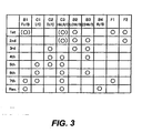
- FIG. 3 is an illustrative view of an engagement operation table according to the first embodiment of this invention.
- FIG. 4 is an illustrative view illustrating operation states of a solenoid valve according to the first embodiment of this invention.
- FIG. 5 is an illustrative view of a shift map according to the first embodiment of this invention.
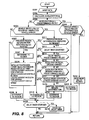
- FIG. 6 is a flowchart showing lockup clutch control executed by an ATCU according to the first embodiment of this invention.
- FIG. 7 is a time chart showing the lockup clutch control executed by the ATCU according to the first embodiment of this invention.
- FIG. 8 is a flowchart showing lockup clutch control executed by an ATCU according to a second embodiment of this invention.
- FIG. 9 is a time chart showing the lockup clutch control executed by the ATCU according to the second embodiment of this invention.
- FIG. 1 is an illustrative view illustrating the constitution of an automatic transmission according to a first embodiment of this invention.
- the automatic transmission according to this embodiment is an automobile transmission having seven forward gear positions and one reverse gear position, which is connected to an engine Eg of a vehicle via a torque converter TC including a lockup clutch LUC.
- Rotation output from the engine Eg is transmitted to a pump impeller and an oil pump OP of the torque converter TC, whereupon oil agitated by rotation of the pump impeller is transmitted to a turbine runner via a stator.
- an input shaft INP is driven.
- the vehicle is further provided with an engine controller (ECU) 10 that controls a driving condition of the engine Eg, an automatic transmission controller (ATCU) 20 that controls a shift condition and so on of the automatic transmission, and a control valve unit (CVU) 30 that executes hydraulic control on a clutch, a brake, and so on based on output signals from the ATCU 20.
- ECU engine controller
- ATCU automatic transmission controller
- CVU control valve unit
- An accelerator opening sensor 1 that detects an accelerator pedal operation amount (accelerator pedal opening) APO generated by a driver, a throttle opening sensor 1a that detects a throttle opening TVO of the engine, and an engine rotation speed sensor 2 that detects an engine rotation speed are connected to the ECU 10.
- the ECU 10 controls a fuel injection amount and the throttle opening, whereby the engine rotation speed and an engine torque are controlled.
- a first turbine rotation speed sensor 3 that detects a rotation speed of a first carrier PC1, a second turbine rotation speed sensor 4 that detects a rotation speed of a first ring gear R1, an output shaft rotation speed sensor 5 that detects a rotation speed of an output shaft OUT, and an inhibitor switch 6 that detects a shift lever operation condition generated by the driver, all of which will be described below, are connected to the ATCU 20.
- the shift lever includes, in addition to P, R, N and D positions, an engine brake range position in which an engine brake is operative and a normal forward travel range position in which the engine brake is inoperative.
- the ATCU 20 includes a rotation speed calculation unit that calculates a rotation speed of the input shaft INP.
- the ATCU 20 sets an optimum target gear position from a shift map of the seven forward speeds, to be described below, on the basis of a vehicle speed Vsp and either the throttle opening TVO or the accelerator pedal opening APO, and outputs a control command to the CVU 30 to realize the target gear position.
- the ATCU 20 performs control to set the lockup clutch LUC of the torque converter TC in an engaged condition or a disengaged condition and outputs a control command to the CVU 30.
- Planetary gear mechanisms are disposed in an axial direction from the input shaft INP side to the output shaft OUT side in order of a first planetary gear set GS1 and a second planetary gear set GS2. Further, a plurality of clutches C1, C2, C3, a plurality of brakes B1, B2, B3, B4, and a plurality of one-way clutches F1, F2 are provided.
- the first planetary gear set GS1 includes two planetary gears G1, G2.
- the first planetary gear G1 is a single pinion planetary gear comprising a first sun gear S1, a first ring gear R1, a first pinion P1 meshed to the two gears S1, R1, and a first carrier PC1 that supports the first pinion P 1 rotationally.
- the second planetary gear G2 is also a single pinion planetary gear and comprises a second sun gear S2, a second ring gear R2, a second pinion P2 meshed to the two gears S2, R2, and a second carrier PC2 that supports the second pinion P2 rotationally.
- the second planetary gear set GS2 includes two planetary gears G3, G4.
- the third planetary gear G3 is a single pinion planetary gear comprising a third sun gear S3, a third ring gear R3, a third pinion P3 meshed to the two gears S3, R3, and a third carrier PC3 that supports the third pinion P3C rotationally.
- the fourth planetary gear G4 similarly to the first to third gear sets, is a single pinion planetary gear comprising a fourth sun gear S4, a fourth ring gear R4, a fourth pinion P4 meshed to the two gears S4, R4, and a fourth carrier PC4 that supports the fourth pinion P4 rotationally.
- the input shaft INP is connected to the second ring gear R2 such that a rotary driving force from the engine Eg is input into the second ring gear R2 via the torque converter TC and so on.
- the output shaft OUT is connected to the third carrier PC3 such that an output rotary driving force is transmitted to a drive wheel via a final gear, not shown in the drawing, and so on.
- the first ring gear R1, second carrier PC2, and fourth ring gear R4 are connected integrally by a first connecting member M1.
- the third ring gear R3 and the fourth carrier PC4 are connected integrally by a second connecting member M2, and the second connecting member M2 is connected to the input shaft INP and the second ring gear R2 via the clutch C1.
- the first sun gear S1 and the second sun gear S2 are connected integrally by a third connecting member M3.
- the first planetary gear G1 and second planetary gear G2 are connected by the first connecting member M1 and the third connecting member M3, and therefore the first planetary gear set GS1 is constituted by four rotary elements.
- the second planetary gear set GS2 the third planetary gear G3 and fourth planetary gear G4 are connected by the second connecting member M2, and therefore the second planetary gear set GS2 is constituted by five rotary elements.
- the first planetary gear set GS1 includes a torque input path for torque input into the second ring gear R2 from the input shaft INP, and the torque input into the first planetary gear set GS1 is output to the second planetary gear set GS2 from the first connecting member M1.
- the second planetary gear set GS2 includes a torque input path for torque input into the second connecting member M2 from the input shaft INP and a torque input path for torque input into the fourth ring gear R4 from the first connecting member M1, and the torque input into the second planetary gear set GS2 is output to the output shaft OUT from the third carrier PC3.
- an input clutch C1 selectively connects and disconnects the input shaft INP and the second connecting member M2, while a direct clutch C2 selectively connects and disconnects the fourth sun gear S4 and the fourth carrier PC4.
- An H&LR clutch C3 selectively connects and disconnects the third sun gear S3 and the fourth sun gear S4.
- a second one-way clutch F2 is disposed between the third sun gear S3 and the fourth sun gear S4.
- the second one-way clutch F2 permits relative rotation between the third sun gear S3 and the fourth sun gear S4 in only one direction and rotates integrally therewith in an opposite direction.
- a front brake B1 selectively halts rotation of the first carrier PC1.
- a first one-way clutch F1 is disposed parallel to the front brake B1.
- a low brake B2 selectively halts rotation of the third sun gear S3.
- a 2346 brake B3 selectively halts rotation of the third connecting member M3 (the first sun gear S1 and second sun gear S2).
- a reverse brake B4 selectively halts rotation of the fourth carrier PC4.
- the input shaft INP is connected to the second ring gear R2 while the first planetary gear G1 and second planetary gear G2 constitute the first planetary gear set GS1 to which two rotary elements are connected, and therefore the rotation speed calculation unit provided in the ATCU 20 detects the rotation speed of the input shaft INP through calculation using the two turbine rotation speed sensors 3, 4.
- the second turbine rotation speed sensor 4 detects the rotation speed of the second carrier PC2, and the first turbine rotation speed sensor 3 detects the rotation speed of a sensor member 63 serving as a turbine sensor member connected to the first carrier PC1.
- the rotation speed of the first carrier PC1 is denoted by N (PC1)
- the rotation speed of the second carrier PC2 is denoted by N (PC2)
- the rotation speed of the second ring gear R2 is denoted by N (R2)
- a gear ratio between the second ring gear R2 and the second carrier PC2 is denoted by 1
- a gear ratio between the first ring gear R1 (second carrier PC2) and the first carrier PC1 is denoted by ⁇
- the rotation speed N (R2) of the second ring gear R2 can be calculated using a following equation.
- the hydraulic circuit is provided with the oil pump OP, which serves as an oil pressure source driven by the engine Eg, a manual valve MV that operates in conjunction with a shift lever operation by the driver to switch an oil passage along which a line pressure PL is supplied, and a pilot valve PV that reduces the line pressure to a predetermined fixed pressure.
- the oil pump OP which serves as an oil pressure source driven by the engine Eg
- a manual valve MV that operates in conjunction with a shift lever operation by the driver to switch an oil passage along which a line pressure PL is supplied
- a pilot valve PV that reduces the line pressure to a predetermined fixed pressure.
- the hydraulic circuit is also provided with a first pressure regulating valve CV1 that regulates an engagement pressure of the low brake B2, a second pressure regulating valve CV2 that regulates an engagement pressure of the input clutch C1, a third pressure regulating valve CV3 that regulates an engagement pressure of the front brake B1, a fourth pressure regulating valve CV4 that regulates an engagement pressure of the H&LR clutch C3, a fifth pressure regulating valve CV5 that regulates an engagement pressure of the 2346 brake B3, and a sixth pressure regulating valve CV6 that regulates an engagement pressure of the direct clutch C2.
- a first pressure regulating valve CV1 that regulates an engagement pressure of the low brake B2
- a second pressure regulating valve CV2 that regulates an engagement pressure of the input clutch C1
- a third pressure regulating valve CV3 that regulates an engagement pressure of the front brake B1
- a fourth pressure regulating valve CV4 that regulates an engagement pressure of the H&LR clutch C3
- a fifth pressure regulating valve CV5 that regulates an engagement pressure of the 2346 brake B
- the hydraulic circuit is further provided with a first switch valve SV1 that switches one of respective oil supply passages 150a, 150b of the low brake B2 and the input clutch C1 to a communicative condition, a second switch valve SV2 that switches one of respective oil supply passages for supplying a D range pressure and an R range pressure to the direct clutch C2 to a communicative condition, a third switch valve SV3 that switches an oil pressure supplied to the reverse brake B4 between an oil pressure supplied from the sixth pressure regulating valve CV6 and an oil pressure supplied from the R range pressure, and a fourth switch valve SV4 that switches an oil pressure output by the sixth pressure regulating valve CV6 between an oil passage 123 and an oil passage 122.
- a first switch valve SV1 that switches one of respective oil supply passages 150a, 150b of the low brake B2 and the input clutch C1 to a communicative condition
- a second switch valve SV2 that switches one of respective oil supply passages for supplying a D range pressure and an R range pressure to the direct clutch
- the hydraulic circuit is further provided with a first solenoid valve SOL1 that outputs a pressure control signal to the first pressure regulating valve CV1, a second solenoid valve SOL2 that outputs a pressure control signal to the second pressure regulating valve CV2, a third solenoid valve SOL3 that outputs a pressure control signal to the third pressure regulating valve CV3, a fourth solenoid valve SOL4 that outputs a pressure control signal to the fourth pressure regulating valve CV4, a fifth solenoid valve SOL5 that outputs a pressure control signal to the fifth pressure regulating valve CV5, a sixth solenoid valve SOL6 that outputs a pressure control signal to the sixth pressure regulating valve CV6, and a seventh solenoid valve SOL7 that outputs a switch signal to the first switch valve SV1 and the third switch valve SV3, on the basis of control signals from the automatic transmission control unit 20.
- a first solenoid valve SOL1 that outputs a pressure control signal to the first pressure regulating valve CV1
- the solenoid valves SOL2, SOL5, SOL6 are respectively constituted by three-way proportioning solenoid valves having three ports, wherein a pilot pressure to be described below is led to a first port, a second port is connected to a drain oil passage, and a third port is connected to a pressure receiving portion of either a pressure regulating valve or a switch valve.
- the solenoid valves SOL1, SOL3, SOL4 are respectively constituted by two-way proportioning solenoid valves having two ports, and the solenoid valve SOL7 is a three-way ON/OFF solenoid valve having three ports.
- the first solenoid valve SOL1, third solenoid valve SOL3, and seventh solenoid valve SOL7 are normally closed (closed when not energized) solenoid valves.
- the second solenoid valve SOL2, fourth solenoid valve SOL4, fifth solenoid valve SOL5, and sixth solenoid valve SOL6, on the other hand, are normally open (open when not energized) solenoid valves.
- An oil passage 105 and an oil passage 106 that supplies the R range pressure, which is selected during reverse travel, are connected to the manual valve MV, and the manual valve MV switches between the oil passage 105 and the oil passage 106 in accordance with the shift lever operation.
- An oil passage 105a that supplies a source pressure of the engagement pressure of the low brake B2, an oil passage 105b that supplies a source pressure of the engagement pressure of the input clutch C1, an oil passage 105c that supplies a source pressure of the engagement pressure of the 2346 brake B3, an oil passage 105d that supplies a source pressure of the engagement pressure of the direct clutch C2, and an oil passage 105e that supplies a switch pressure of the second switch valve SV2, to be described below, are connected to the oil passage 105.
- An oil passage 106a that supplies the switch pressure of the second switch valve SV2, an oil passage 106b that supplies the source pressure of the engagement pressure of the direct clutch C2, and an oil passage 106c that supplies the engagement pressure of the reverse brake B4 are connected to the oil passage 106.
- An oil passage 103 that supplies the pilot pressure via the pilot valve PV is connected to the oil passage 102.
- the oil passage 103 is provided with an oil passage 103a that supplies the pilot pressure to the first solenoid valve SOL1, an oil passage 103b that supplies the pilot pressure to the second solenoid valve SOL2, an oil passage 103c that supplies the pilot pressure to the third solenoid valve SOL3, an oil passage 103d that supplies the pilot pressure to the fourth solenoid valve SOL4, an oil passage 103e that supplies the pilot pressure to the fifth solenoid valve SOL5, an oil passage 103f that supplies the pilot pressure to the sixth solenoid valve SOL6, and an oil passage 103g that supplies the pilot pressure to the seventh solenoid valve SOL7.
- the hydraulic circuit also includes a circuit for supplying oil pressure to a piston oil chamber 62 of the lockup clutch LUC.
- the first speed different clutches and brakes are operated depending on whether the engine brake is operative (an engine brake range position has been selected) or inoperative (a normal forward travel range position has been selected).
- the first speed is obtained by engaging the front brake B1, the low brake B2, and the H&LR clutch C3.
- the first one-way clutch F1 provided parallel to the front brake B1 and the second one-way clutch F2 provided parallel to the H&LR clutch C3 also contribute to torque transmission.
- the front brake B1 and the H&LR clutch C3 are disengaged such that only the low brake B2 is engaged, and torque is transmitted by the first one-way clutch F1 and second one-way clutch F2.
- the front brake B1 In the first speed, the front brake B1 is engaged (engaged by the first one-way clutch F1 when the engine brake is inoperative), and therefore rotation input into the second ring gear R2 from the input shaft INP is reduced by the first planetary gear set GS1. This reduced rotation is output to the fourth ring gear R4 from the first connecting member M1. Further, the low brake B2 and the H&LR clutch C3 are engaged (engaged by the low brake B2 and the second one-way clutch F2 when the engine brake is inoperative), and therefore rotation input into the fourth ring gear R4 is reduced by the second planetary gear set and output from the third carrier PC3.
- first speed torque acts on the front brake B1 (or the first one-way clutch F1), the low brake B2, the H&LR clutch C3 (or the second one-way clutch F2), the first connecting member M1, the second connecting member M2, and the third connecting member M3.
- first planetary gear set GS1 and second planetary gear set GS2 contribute to torque transmission.
- engagement pressure is supplied to the desired clutches and brakes by switching the first to third solenoid valves SOL1 to SOL3 and the sixth and seventh solenoid valves SOL6, SOL7 ON and switching the other solenoid valves OFF.
- the seventh solenoid valve SOL7 is ON, the first switch valve SV1 moves to the left of FIG. 2 such that the first pressure regulating valve CV1 communicates with the low brake B2 and the input clutch C1 is connected to a drain (thus an interlocking condition is prevented). Furthermore, since the D range pressure is exerted on a fourth port c4, the second switch valve SV2 moves to the left in FIG. 2 such that a first port c1 communicates with a third port c3, and therefore the D range pressure acts on the sixth pressure regulating valve CV6. The sixth pressure regulating valve CV6 moves downward in FIG. 2 , and therefore the D range pressure is not supplied to the direct clutch C2 and the fourth switch valve SV4.
- the D range pressure causes the fourth switch valve SV4 to move to the right of FIG. 2 such that the oil passage 121 communicates with the oil passage 123, but this bears no relation to the engagement operation. Further, a signal pressure is supplied to a port d4 from the seventh solenoid valve SOL7, and therefore the third switch valve SV3 moves to the left in FIG. 2 such that a first port d1 communicates with a third port d3, but since no oil pressure is supplied to the oil passage 122, no oil pressure is supplied to the reverse brake B4.
- the second speed different clutches and brakes are engaged depending on whether the engine brake is operative (the engine brake range position has been selected) or inoperative (the normal forward travel range position has been selected).
- the second speed is obtained by engaging the low brake B2, the 2346 brake B3, and the H&LR clutch C3.
- the second one-way clutch F2 provided parallel to the H&LR clutch C3 also contributes to torque transmission.
- the H&LR clutch C3 is disengaged and the low brake B2 and 2346 brake B3 are engaged, and torque is transmitted by the second one-way clutch F2.
- the 2346 brake B3 In the second speed, the 2346 brake B3 is engaged, and therefore the rotation input into the second ring gear R2 from the input shaft INP is reduced by the second planetary gear G2 alone. This reduced rotation is output to the fourth ring gear R4 from the first connecting member M1.
- the low brake B2 and the H&LR clutch C3 are engaged (engaged by the second one-way clutch F2 when the engine brake is inoperative), and therefore the rotation input into the fourth ring gear R4 is reduced by the second planetary gear set and output from the third carrier PC3.
- the first one-way clutch F1 is disengaged at a point where an engagement capacity of the 2346 brake B3 is secured by disengaging the front brake B 1 slightly early and then starting to engage the 2346 brake B3. In so doing, an improvement in shift timing precision can be achieved.
- engagement pressure is supplied to the desired clutches and brakes by switching the first, second, and fifth to seventh solenoid valves SOL1, SOL2, SOL5, SOL6, SOL7 ON and switching the other solenoid valves OFF.
- the third speed is obtained by engaging the 2346 brake B3, the low brake B2, and the direct clutch C2.
- the 2346 brake B3 is engaged, and therefore the rotation input into the second ring gear R2 from the input shaft INP is reduced by the second planetary gear G2.
- This reduced rotation is output to the fourth ring gear R4 from the first connecting member M1.
- the direct clutch C2 is engaged, and therefore the fourth planetary gear G4 rotates integrally.
- the low brake B2 is engaged, and therefore rotation input into the third ring gear R3 from the fourth carrier PC4, which rotates integrally with the fourth ring gear R4, via the second connecting member M2 is reduced by the third planetary gear G3 and output from the third carrier PC3.
- the fourth planetary gear G4 contributes to torque transmission but does not contribute to the reduction operation.
- the third speed is defined by a line linking an engagement point of the 2346 brake B3 that reduces the rotation output from the engine and an engagement point of the low brake B2 that reduces the reduced rotation from the second planetary gear G2, and therefore the rotation input from the input shaft INP is reduced and output from the output shaft OUT.
- the second one-way clutch F2 is disengaged at a point where an engagement capacity of the direct clutch C2 is secured by disengaging the H&LR clutch C3 slightly early and then starting to engage the direct clutch C2. In so doing, an improvement in shift timing precision can be achieved.
- engagement pressure is supplied to the desired clutches and brakes by switching the first, second, fourth, fifth and seventh solenoid valves SOL1, SOL2, SOL4, SOL5, SOL7 ON and switching the other solenoid valves OFF.
- the fourth speed is obtained by engaging the 2346 brake B3, the direct clutch C2, and the H&LR clutch C3.
- the 2346 brake B3 In the fourth speed, the 2346 brake B3 is engaged, and therefore the rotation input into the second ring gear R2 from the input shaft INP is reduced by the second planetary gear G2 alone. This reduced rotation is output to the fourth ring gear R4 from the first connecting member M1.
- the direct clutch C2 and the H&LR clutch C3 are engaged, and therefore the second planetary gear set GS2 rotates integrally. Hence, the rotation input into the fourth ring gear R4 is output from the third carrier PC3 as is.
- engagement pressure is supplied to the desired clutches and brakes by switching the second and fifth solenoid valves SOL2, SOL5 ON and switching the other solenoid valves OFF.
- the seventh solenoid valve SOL7 is OFF, the first switch valve SV1 moves to the right of FIG. 2 such that the low brake B2 communicates with a drain circuit and the second pressure regulating valve CV2 communicates with the input clutch C1 (an interlocking condition is prevented). Furthermore, since the D range pressure is exerted on the fourth port c4, the second switch valve SV2 moves to the left in FIG. 2 such that the first port c1 communicates with the third port c3. The sixth pressure regulating valve CV6 moves upward in FIG. 2 , and therefore regulated oil pressure is supplied to the fourth switch valve SV4.
- the D range pressure acts on the fourth switch valve SV4, and therefore the oil passage 121 communicates with the oil passage 123.
- the oil passage 122 communicates with the drain circuit, and therefore oil pressure is supplied to the direct clutch C2 but not supplied to the third switch valve SV3.
- the signal pressure is not supplied to the port d4 from the seventh solenoid valve SOL7, and therefore the third switch valve SV3 moves to the right in FIG. 2 .
- the second port d2 communicates with the third port d3 but the R range pressure is not supplied to the oil passage 106c (the R range pressure is blocked by the manual valve MV), and therefore no oil pressure is supplied to the reverse brake B4.
- the fifth speed is obtained by engaging the input clutch C1, the direct clutch C2, and the H&LR clutch C3.
- the input clutch C 1 In the fifth speed, the input clutch C 1 is engaged, and therefore the rotation of the input shaft INP is input into the second connecting member M2.
- the direct clutch C2 and the H&LR clutch C3 are engaged, and therefore the third planetary gear G3 rotates integrally. Hence, the rotation of the input shaft INP is output from the third carrier PC3 as is.
- the sixth speed is obtained by engaging the input clutch C1, the H&LR clutch C3, and the 2346 brake B3.
- the input clutch C1 is engaged, and therefore the rotation of the input shaft INP is input into the second ring gear and the second connecting member M2.
- the 2346 brake B3 is engaged, and therefore the rotation reduced by the second planetary gear G2 is output to the fourth ring gear R4 from the first connecting member M1.
- the H&LR clutch C3 is engaged, and therefore the second planetary gear set GS2 outputs rotation defined by the rotation of the fourth ring gear R4 and the rotation of the second connecting member M2* from the third carrier PC3.
- torque acts on the input clutch C1, the H&LR clutch C3, the 2346 brake B3, the first connecting member M1, the second connecting member M2, and the third connecting member M3.
- the second planetary gear G2 and the second planetary gear set GS2 contribute to torque transmission.
- engagement pressure is supplied to the desired clutches and brakes by switching the fifth and sixth solenoid valves SOL5, SOL6 ON and switching the other solenoid valves SOL1, SOL2, SOL3, SOL4, SOL7 OFF.
- the seventh speed is obtained by engaging the input clutch C1, the H&LR clutch C3, and the front brake B1 (the one-way clutch F1).
- the input clutch C1 is engaged, and therefore the rotation of the input shaft INP is input into the second ring gear and the second connecting member M2.
- the front brake B1 is engaged, and therefore the rotation reduced by the first planetary gear set GS1 is output to the fourth ring gear R4 from the first connecting member M1.
- the H&LR clutch C3 is engaged, and therefore the second planetary gear set GS2 outputs rotation defined by the rotation of the fourth ring gear R4 and the rotation of the second connecting member M2* from the third carrier PC3.
- engagement pressure is supplied to the desired clutches and brakes by switching the third and sixth solenoid valves SOL3, SOL6 ON and switching the other solenoid valves SOL1, SOL2, SOL4, SOL5, SOL7 OFF.
- reverse is obtained by engaging the H&LR clutch C3, the front brake B1, and the reverse brake B4.
- the front brake B1 In reverse, the front brake B1 is engaged, and therefore the rotation reduced by the first planetary gear set GS1 is output to the fourth ring gear R4 from the first connecting member M1.
- the H&LR clutch C3 is engaged and the reverse brake B4 is engaged, and therefore the second planetary gear set GS2 outputs rotation defined by the rotation of the fourth ring gear R4 and a fixed condition of the second connecting member M2 from the third carrier PC3.
- reverse is defined by a line linking respective engagement points of the front brake B1 that reduces the rotation output from the engine via the first planetary gear set GS1, the reverse brake B4 that fixes the rotation of the second connecting member M2, and the H&LR clutch C3 constituting the second planetary gear set GS2, and therefore the rotation input from the input shaft INP is reduced in an opposite direction and output from the output shaft OUT.
- first planetary gear set GS1 and second planetary gear set GS2 contribute to torque transmission.
- engagement pressure is supplied to the desired clutches and brakes by switching the second, third and sixth solenoid valves SOL2, SOL3, SOL6 ON and switching the other solenoid valves SOL1, SOL4, SOL5, SOL7 OFF.
- the seventh solenoid valve SOL7 is switched ON at the beginning of an R range switch and switched OFF following engagement completion.
- the R range pressure is supplied to the reverse brake B4 via the third switch valve SV3.
- the R range does not have a dedicated pressure regulating valve, and therefore, at the beginning of engagement, the sixth pressure regulating valve CV6 used in the direct clutch C2 is employed to regulate the engagement pressure of the reverse brake B4.
- the second switch valve SV2 moves to the right in FIG. 2 such that the R range pressure is supplied to the sixth pressure regulating valve CV6.
- the fourth switch valve SV4 moves to the left in FIG. 2 such that the oil passage 121 communicates with the oil passage 122.
- oil pressure regulated by the sixth pressure regulating valve CV6 is led into the oil passage 122.
- the third switch valve SV3 moves to the left in FIG. 2 such that the oil passage 122 communicates with an oil passage 130.
- the engagement pressure of the reverse brake B4 is controlled by oil pressure regulated by the sixth pressure regulating valve CV6.
- the seventh solenoid valve SOL7 is switched OFF. Accordingly, the third switch valve SV3 moves to the right in FIG. 2 such that the oil passage 106c communicates with the oil passage 130, and as a result, the R range pressure is introduced as is, whereby the engaged condition is maintained.
- the engagement pressures of two clutches or brakes can be controlled using a single pressure regulating valve.
- a normal seven speed shift map has the characteristics shown in FIG. 5 , for example, wherein shift regions are defined using the vehicle speed Vsp calculated on the basis of the output shaft rotation speed sensor 5 and the accelerator opening APO obtained by the accelerator opening sensor 1 as parameters and an upshift or a downshift is executed when an upshift line or a downshift line is crossed.
- the ATCU 20 obtains an operating condition of the vehicle and determines whether to set the lockup clutch LUC of the torque converter TC in an engaged condition or a disengaged condition on the basis of the operating condition.
- the engagement condition of the lockup clutch LUC of the torque converter TC is then controlled on the basis of the determination result.
- the ATCU 20 obtains the vehicle speed Vsp as the operating condition.
- the ATCU 20 compares the vehicle speed Vsp to a lockup region determination vehicle speed (Slip L/U region determination vehicle speed) indicated by a dot-dash line on the shift map in FIG. 5 .
- a lockup region is determined, and therefore the ATCU 20 controls the lockup clutch LUC to the engaged condition.
- a torque converter (T/C) region is determined, and therefore the ATCU 20 controls the lockup clutch LUC to the disengaged condition.
- the engagement condition of the lockup clutch LUC includes slip lockup (also referred to as "Slip L/U” hereafter), in which a difference between an input rotation speed and an output rotation speed of the torque converter TC is controlled to a predetermined range (several tens of rpm, for example).
- the engagement condition of the lockup clutch LUC of the torque converter TC is controlled on the basis of the operating condition of the vehicle.
- a determination reference (vehicle speed) at which the lockup clutch LUC is set in the engaged condition and a determination reference (vehicle speed) at which the lockup clutch LUC is set in the disengaged condition are identical, and therefore the engagement region of the lockup clutch LUC is enlarged, leading to an improvement in fuel efficiency.
- hunting is suppressed by executing control to be described below.
- FIG. 6 is a flowchart showing control of the lockup clutch LUC executed by the ATCU 20 according to this embodiment.
- the flowchart of FIG. 6 is executed by the ATCU 20 at predetermined intervals (every 10 ms, for example).
- the ATCU 20 obtains data relating to current operating conditions of the vehicle (S101). More specifically, the ATCU 20 obtains signals from the first turbine rotation speed sensor 3, the second turbine rotation speed sensor 4, the output shaft rotation speed sensor 5, the inhibitor switch 6, and so on. Further, the accelerator pedal opening APO, the engine rotation speed N, and so on are obtained from the ECU 10.
- the ATCU 20 then obtains data (the vehicle speed Vsp, the accelerator pedal opening APO, and so on) relating to the control to be executed on the basis of the signal values obtained from the respective sensors.
- the ATCU 20 refers to a pre-stored shift map ( FIG. 5 ) to determine whether or not the obtained vehicle speed Vsp is in the engagement region, or in other words whether or not the vehicle speed Vsp is equal to or higher than the Slip L/U region determination vehicle speed (S102).
- the routine advances to a step S103.
- the routine advances to a step S109.
- the ATCU 20 determines whether or not a previous region determination result indicates the Slip L/U region.
- the previously determined region is a determination result obtained during control (steps S104, S105, S110, S117) executed immediately before the control according to this flowchart.
- the routine advances to a step S104.
- the routine advances to a step S105.
- the current vehicle speed Vsp is smaller than the Slip L/U region determination vehicle speed and the previous determination result indicates the T/C region, and therefore the ATCU 20 determines that the lockup clutch LUC is to remain in the T/C region.
- the routine then advances to a step S107, in which the ATCU 20 determines whether or not a Slip L/U region determination delay timer has already been started.
- the Slip L/U region determination delay timer is used to measure a time period during which hunting is suppressed following disengagement of the lockup clutch LUC, as will be described below.
- the ATCU 20 counts up the Slip L/U region determination delay timer by adding 1 thereto, whereby the Slip L/U region determination delay timer is updated (S108). The processing according to this flowchart is then temporarily terminated. When the Slip L/U region determination delay timer has not been started, the processing according to this flowchart is temporarily terminated as is.
- the ATCU 20 determines in the step S103 that the previous determination result indicates the Slip L/U region, the current vehicle speed Vsp is smaller than the Slip L/U region determination vehicle speed, and therefore the ATCU 20 determines that the lockup clutch LUC is in the T/C region in the step S105.
- a step S106 the ATCU 20 executes initialization processing accompanying a shift from the Slip L/U region to the T/C region.
- the lockup clutch LUC is not shifted to the Slip L/U region unless a predetermined condition is established, even if the vehicle speed Vsp is equal to or higher than the Slip L/U region determination vehicle speed.
- An initial value for determining establishment of the predetermined condition is set in the step S106.
- the ATCU 20 then starts the Slip L/U region determination delay timer. Further, the ATCU 20 stores the accelerator pedal opening APO obtained in the step S101, information indicating whether or not the accelerator pedal opening APO is fully closed, and the vehicle speed Vsp.
- the routine then advances to a step S107, in which the ATCU 20 determines whether or not the Slip L/U region determination delay timer has already been started.
- the routine advances to the step S107 following the processing of the step S106, the Slip L/U region determination delay timer has already been started, and therefore the routine advances to a step S108, in which the ATCU 20 counts up the Slip L/U region determination delay timer. The processing according to this flowchart is then temporarily terminated.
- the routine advances to a step S109.
- the ATCU 20 determines whether or not the previous region determination result indicates the T/C region.
- the previously determined region is the determination result obtained during the control executed immediately before the control according to this flowchart.
- the routine advances to a step S110.
- the current vehicle speed Vsp is equal to or higher than the Slip L/U region determination vehicle speed and the previous determination result indicates the Slip L/U region, and therefore the ATCU 20 determines that the lockup clutch LUC is to remain in the Slip L/U region.
- the routine then advances to the step S107, and when the Slip L/U region determination delay timer has already been started, the ATCU 20 counts up the Slip L/U region determination delay timer (S108). The processing according to this flowchart is then temporarily terminated. When the Slip L/U region determination delay timer has not been started, the processing according to this flowchart is temporarily terminated as is.
- the routine advances to a step S111.
- the ATCU 20 determines whether or not the Slip L/U region determination delay timer has already been started.
- the routine advances to a step S112.
- the routine advances to the step S110.
- the step S111 corresponds to a case in which the previous determination result indicates the T/C region but the vehicle speed Vsp was determined to be equal to or higher than the Slip L/U region determination vehicle speed in the step S102.
- the slip L/U region determination delay timer when the Slip L/U region determination delay timer has already been started, this indicates that the initialization processing of the step S106 was executed, the processing according to this flowchart was temporarily terminated, and then the processing according to this flowchart was restarted.
- a last but one determination result indicates the Slip L/U condition and the previous determination result obtained in the step S105 indicates the T/C condition. Therefore, if the Slip L/U condition is set immediately thereafter on the basis of the vehicle speed Vsp, hunting will occur.
- the Slip L/U condition is set only when at least one of predetermined conditions defined in steps S112 to S115 is established.
- the lockup clutch condition is not shifted to the Slip L/U condition even if the vehicle speed Vsp is equal to or greater than the Slip L/U region determination vehicle speed, and instead the T/C condition is maintained.
- the predetermined conditions according to this embodiment are that the Slip L/U region determination delay timer has expired (S112), the accelerator pedal opening APO has varied between a fully closed and a non-fully closed condition (S113), the accelerator pedal opening APO has varied by at least a predetermined amount (S114), and the vehicle speed Vsp has varied by at least a predetermined amount (S115).
- S112 the Slip L/U region determination delay timer has expired
- S113 the accelerator pedal opening APO has varied between a fully closed and a non-fully closed condition
- the accelerator pedal opening APO has varied by at least a predetermined amount (S114)
- the vehicle speed Vsp has varied by at least a predetermined amount (S115).
- the ATCU 20 determines whether or not a value of the Slip L/U region determination delay timer equals or exceeds a predetermined value.
- the processing advances to the step S110, in which the Slip L/U condition is set.
- the processing advances to a step S113.
- the Slip L/U region determination delay timer is set as an expiration time such that the timing at which the lockup clutch condition reenters the Slip L/U condition after switching from the Slip L/U condition to the T/C condition is not experienced by the driver as hunting.
- the timing at which a shift is performed following another shift is controlled to or above a predetermined time interval (two seconds, for example) to ensure that the driver does not experience so-called "busy-shift".
- a predetermined time interval two seconds, for example
- the ATCU 20 determines whether or not the condition of the accelerator pedal has varied. More specifically, the ATCU 20 determines whether the condition of the accelerator pedal has varied from a non-fully closed condition to a fully closed condition or from a fully close condition to a non-fully close condition.
- the processing advances to the step S110, in which the Slip L/U condition is set.
- the processing advances to a step S114.
- the driver controls the speed and acceleration of the vehicle by adjusting the opening of the accelerator pedal.
- the driver operates the accelerator pedal intentionally, s/he is able to predict variation in the behavior of the vehicle generated as a result of the operation, and therefore his/her tolerance for hunting is larger than when the pedal is operated unintentionally.
- the ATCU 20 determines in this step S113 that the driver has operated the accelerator pedal intentionally by taking his/her foot off the accelerator pedal or depressing the pedal from a state of release, the tolerance of the driver is large, and therefore, even if the control will cause hunting, the Slip L/U region is set immediately.
- the fuel efficiency can be improved by actively setting the lockup clutch in the engaged condition.
- the ATCU 20 determines whether or not variation in the accelerator pedal opening APO is equal to or greater than a predetermined amount.
- the variation in the accelerator pedal opening APO is calculated from an absolute value of a difference between the accelerator pedal opening APO stored in the step S106 of the control executed in the previous flowchart and the accelerator pedal opening APO obtained in the step S101 of the current control.
- the routine advances to the step S110, in which the Slip L/U condition is set.
- the processing advances to a step S115.
- a case in which variation in the accelerator pedal opening APO is large indicates that the driver actively intends to accelerate or decelerate, and in this case the fuel efficiency can be improved by actively setting the lockup clutch in the engaged condition.
- the ATCU 20 determines whether or not variation in the vehicle speed Vsp is equal to or greater than a predetermined amount.
- the variation in the vehicle speed Vsp is calculated from an absolute value of a difference between the vehicle speed Vsp stored in the step S106 of the control executed in the previous flowchart and the vehicle speed Vsp obtained in the step S101 of the current control.
- the routine advances to the step S110, in which the Slip L/U condition is set.
- the processing advances to a step S116.
- Variation in the vehicle speed Vsp results from an intention of the driver to accelerate or decelerate. Hence, when the driver actively intends to accelerate or decelerate, his/her tolerance for hunting is large. Therefore, when the variation in the vehicle speed Vsp is large, or more specifically equal to or larger than the predetermined amount, the tolerance of the driver is large, and therefore, even if the control will cause hunting, the Slip L/U region is set.
- hysteresis is set between engagement/disengagement determination values of the lockup clutch LCU in order to prevent hunting.
- Hysteresis is also set in relation to gear position modification in a conventional stepped transmission.
- the hysteresis is normally set at approximately 3km/h.
- the processing advances to the step S116, in which the ATCU 20 decides to maintain the previous region determination result.
- the ATCU 20 determines in a step S117 that the lockup clutch LUC is in the T/C region.
- the processing then advances to the step S107, and when the Slip L/U region determination delay timer has already been started, the ATCU 20 counts up the Slip L/U region determination delay timer (S108). The processing according to this flowchart is then temporarily terminated. When the Slip L/U region determination delay timer has not been started, the processing according to this flowchart is terminated as is.
- FIG. 7 is a time chart showing the control performed on the lockup clutch LUC by the ATCU 20 according to this embodiment.
- the time chart in FIG. 7 shows, in descending order, the condition of the lockup clutch LUC, variation in the accelerator pedal opening APO, the result of the comparison between the variation in the accelerator pedal opening APO and the predetermined value, the result of the comparison between the variation in the vehicle speed Vsp and the predetermined value, the accelerator pedal condition, the condition of the Slip L/U region determination delay timer, variation in the accelerator pedal opening APO, and variation in the vehicle speed Vsp.
- condition (command value) of the lockup clutch LUC corresponds to the T/C condition.
- the ATCU 20 determines at a timing t1 that the vehicle speed Vsp is equal to or higher than the Slip L/U region determination vehicle speed ("YES" in the step S102 of FIG. 6 )
- the ATCU 20 determines that the previous region determination indicates T/C ("YES” in the step S109) and that the Slip L/U region determination delay timer has not yet been started ("NO” in the step S111), and therefore the processing advances to the step S110, in which the Slip L/U condition is determined.
- the ATCU 20 determines at a timing t2 that the vehicle speed Vsp is lower than the Slip L/U region determination vehicle speed ("NO" in the step S102 of FIG. 6 ), the ATCU 20 determines that the previous region determination indicates Slip L/U ("YES" in the step S103), and therefore the processing advances to the step S105, in which the T/C condition is determined.
- the ATCU 20 executes the initialization control of the step S106, whereby the Slip L/U region determination delay timer is started.
- the ATCU 20 then stores the accelerator pedal condition, the accelerator pedal opening APO, and the vehicle speed Vsp at the timing t2.
- the ATCU 20 determines at a timing t3 that the vehicle speed Vsp is equal to or higher than the Slip L/U region determination vehicle speed ("YES" in the step S102), the ATCU 20 determines that the previous region determination indicates T/C ("YES" in the step S109) and that the Slip L/U region determination delay timer has already been started (“YES” in the step S111), and therefore the ATCU 20 determines whether or not the predetermined conditions defined in the steps S112 to S115 of FIG. 6 are established.
- the ATCU 20 determines whether or not the Slip L/U region determination delay timer has expired. At the timing t3, the Slip L/U region determination delay timer has not yet expired, and therefore this condition is not established.
- the ATCU 20 determines whether or not the condition of the accelerator pedal has varied to the fully closed condition. At the timing t3, the condition of the accelerator pedal has not varied, and therefore this condition is not established.
- the ATCU 20 determines whether or not the variation in the accelerator pedal opening APO is equal to or greater than the predetermined value. At the timing t3, the variation in the accelerator pedal opening APO is smaller than the predetermined value, and therefore this condition is not established.
- the ATCU 20 determines whether or not the variation in the vehicle speed Vsp is equal to or greater than the predetermined value. At the timing t3, the variation in the vehicle speed Vsp is smaller than the predetermined value, and therefore this condition is not established.
- the ATCU 20 maintains the T/C region even though the vehicle speed Vsp is equal to or greater than the Slip L/U region determination vehicle speed.
- the ATCU 20 repeats the determination as to whether or not the predetermined conditions defined in the steps S112 to S115 of FIG. 6 are established. During this repetition, the Slip L/U region determination delay timer is counted up through the processing of the steps S107 and S108 in FIG. 6 .
- the processing advances to the step S110, in which the lockup clutch LUC is shifted to the Slip L/U region.
- the ATCU 20 executes control to ensure that the driver does not sense hunting.
- the reference value for determining that the lockup clutch LUC of the torque converter TC is to be set in the engaged condition (Slip L/U) and the reference value for determining that the lockup clutch LUC is to be set in the disengaged condition (T/C) are identical, and no hysteresis is set therein. In so doing, the region in which the lockup clutch LUC is engaged can be enlarged, enabling an improvement in fuel efficiency.
- the ATCU 20 stores the vehicle conditions (the condition of the accelerator pedal, the accelerator pedal opening APO and the vehicle speed Vsp), and when the reference value subsequently enters an engagement region, the ATCU 20 compares the stored vehicle conditions with the current vehicle conditions and returns the lockup clutch LUC to the engaged condition only when a predetermined condition is established. In so doing, the unpleasant sensation experienced by the driver due to control hunting occurring when the lockup clutch LUC is switched repeatedly between the engaged condition and the disengaged condition can be reduced.
- vehicle conditions the condition of the accelerator pedal, the accelerator pedal opening APO and the vehicle speed Vsp
- the basic constitution of the second embodiment is identical to that of the first embodiment, and therefore description thereof has been omitted.
- FIG. 8 is a flowchart showing control of the lockup clutch LUC executed by the ATCU 20 according to the second embodiment of this invention.
- the flowchart in FIG. 8 is executed by the ATCU 20 at predetermined intervals (every 10 ms, for example).
- the ATCU 20 obtains data relating to the current operating conditions of the vehicle (the vehicle speed Vsp, the accelerator pedal opening APO, the rotation speeds of the respective rotation speed sensors, and so on) (S201).
- the ATCU 20 calculates a current vehicle acceleration (a) (S202).
- the ATCU 20 determines whether or not the calculated acceleration (a) is equal to or greater than a predetermined value.
- the processing advances to a step S220, and when the acceleration (a) is determined to be smaller than the predetermined value, the processing advances to a step S204.
- the determination relating to establishment of the predetermined conditions is not made, and instead, the engagement determination relating to the lockup clutch LUC is made on the basis of the vehicle speed alone.
- the processing advances to the step S220, in which a determination is made as to whether or not the vehicle speed Vsp is equal to or higher than the Slip L/U region determination vehicle speed.
- the processing advances to a step S221, in which the ATCU 20 determines the T/C region.
- the processing advances to a step S222, in which the ATCU 20 determines the Slip L/U region.
- step S203 When the ATCU 20 determines in the step S203 that the vehicle acceleration (a) is smaller than the predetermined value, the processing advances to the step S204.
- Control executed in steps S204 to S219 is identical to that of the first embodiment, and therefore description thereof has been omitted.
- FIG. 9 is a time chart showing the control performed on the lockup clutch LUC by the ATCU 20 in the second embodiment.
- the time chart in FIG. 9 shows, in descending order, the condition of the lockup clutch LUC, the condition of the accelerator pedal, the condition of the Slip L/U region determination delay timer, the condition of the acceleration (a), variation in the accelerator pedal opening APO, and variation in the vehicle speed Vsp.
- condition (command value) of the lockup clutch LUC corresponds to the T/C condition.
- the ATCU 20 determines at a timing t1 that the acceleration (a) is smaller than the predetermined value ("NO” in the step S203 of FIG. 8 ) and the vehicle speed Vsp is equal to or higher than the Slip L/U region determination vehicle speed ("YES” in the step S204 of FIG. 8 ), the ATCU 20 determines that the previous region determination indicates T/C ("YES" in a step S211 of FIG. 8 ) and that the Slip L/U region determination delay timer has not yet been started ("NO" in a step S213 of FIG. 8 ), and therefore the processing advances to a step S212, in which the Slip L/U condition is determined.
- the ATCU 20 determines at a timing t2 that the acceleration (a) is smaller than the predetermined value ("NO" in the step S203 of FIG. 8 ) and the vehicle speed Vsp is lower than the Slip L/U region determination vehicle speed ("NO" in the step S204), the ATCU 20 determines that the previous region determination indicates Slip L/U ("YES" in the step S205 of FIG. 8 ), and therefore the processing advances to a step S207, in which the T/C condition is determined.
- the ATCU 20 then executes initialization control in a step S208.
- the ATCU 20 determines at a timing t3 that the acceleration (a) is smaller than the predetermined value ("NO” in the step S203 of FIG 8 ) and the vehicle speed Vsp is equal to or greater than the Slip L/U region determination vehicle speed ("YES” in the step S204 of FIG. 8 ), the ATCU 20 determines that the previous region determination indicates T/C ("YES” in the step S211 of FIG. 8 ) and that the Slip L/U region determination delay timer has already been started (“YES” in the step S213 of FIG. 8 ), and therefore the ATCU 20 determines whether or not predetermined conditions defined in steps S214 to S217 of FIG. 8 are established.
- the predetermined conditions are not established at the timing t3, and therefore the ATCU 20 maintains the T/C region even though the vehicle speed Vsp is equal to or higher than the Slip L/U region determination vehicle speed.
- the engagement determination relating to the lockup clutch LUC is made only on the basis of whether or not the vehicle speed Vsp is equal to or higher than the Slip L/U region determination vehicle speed.
- the processing advances to the step S222, in which the lockup clutch LUC is shifted to the Slip L/U region.
- control is performed such that an improvement in fuel efficiency is achieved without causing the driver to sense hunting.
- acceleration is used to determine engagement/disengagement of the lockup clutch LUC of the torque converter TC.
- the determination is made using only the vehicle speed, i.e. without determining whether or not the predetermined conditions are established, and therefore an enlargement in the engagement region can be achieved while improving the fuel efficiency and reducing hunting.
- a seven speed automatic transmission was described as an example, but this invention is not limited thereto and may be applied to another stepped transmission.
- This invention may also be applied to a belt type continuously variable transmission in which a belt, a chain, or similar is sandwiched between pulleys, or a toroidal (full toroidal/half toroidal) continuously variable speed change mechanism in which a power roller is sandwiched between input/output disks.
Landscapes
- Engineering & Computer Science (AREA)
- General Engineering & Computer Science (AREA)
- Mechanical Engineering (AREA)
- Control Of Transmission Device (AREA)
- Control Of Fluid Gearings (AREA)
Claims (4)
- Steuerungsvorrichtung (ATCU) für ein Automatikgetriebe, das einen Drehmomentwandler (TC) umfasst, in welchem eine Ziel-Gangposition basierend auf einer Fahrzeuggeschwindigkeit und einer Motorlast eingestellt wird, umfassend:eine Fahrzeuggeschwindigkeits-Erfassungseinrichtung, die zum Erfassen der Fahrzeuggeschwindigkeit ausgelegt ist;eine Speichereinrichtung, die zum Speichern einer Ermittlungsreferenz für die Fahrzeuggeschwindigkeit ausgelegt ist, die zum Ermitteln verwendet wird, ob ein Reibelement (63) zum Sperren des Drehmomentwandlers (TC) in einen eingerückten Zustand oder einen ausgerückten Zustand versetzt ist;eine Ermittlungseinrichtung, die zum Ermitteln, dass das Reibelement (63) in den eingerückten Zustand zu versetzen ist, falls die Fahrzeuggeschwindigkeit gleichhoch oder höher als die Ermittlungsreferenz für die Fahrzeuggeschwindigkeit ist, und zum Ermitteln ausgelegt ist, dass das Reibelement (63) in den ausgerückten Zustand zu versetzen ist, falls die Fahrzeuggeschwindigkeit niedriger als die Ermittlungsreferenz für die Fahrzeuggeschwindigkeit ist; undeine Einrücksteuerungseinrichtung, die zum Ausführen einer Steuerung zum Einrücken oder Ausrücken des Reibelements (63) basierend auf einer Ermittlung ausgelegt ist, dass das Reibelement in den eingerücktem Zustand oder in den ausgerückten Zustand der Ermittlungseinrichtung zu versetzen ist,wobei die Einrücksteuerungseinrichtung eine Verhinderungseinrichtung aufweist, die zum Verhindern eines Einstellens des Reibelements (63) in den eingerückten Zustand ausgelegt ist, bis ein vorgegebener Zustand eingerichtet ist, wenn die Ermittlungseinrichtung ermittelt hat, dass das Reibelement in den eingerückten Zustand zu versetzen ist, nachdem das Reibelement (63) basierend auf der Fahrzeuggeschwindigkeit vom eingerückten Zustand in den ausgerückten Zustand gesteuert wurde, und- wobei die Einrücksteuerungseinrichtung ermittelt, dass der vorgegebene Zustand eingerichtet ist, falls eine vorgegebene Zeitspanne abgelaufen ist, nachdem das Reibelement (63) in den ausgerückten Zustand vom eingerückten Zustand gesteuert wurde, oder- wobei die Einrücksteuerungseinrichtung ermittelt, dass der vorgegebene Zustand eingerichtet ist, falls eine Gaspedal-Öffnung von einem nicht vollständig geschlossenen Zustand in einem vollständig geschlossenen Zustand, oder von einem vollständig geschlossenen Zustand in einen nicht vollständig geschlossenen Zustand wechselt, nachdem das Reibelement (63) in den ausgerückten Zustand vom eingerückten Zustand gesteuert wurde, oder- wobei die Einrücksteuerungseinrichtung ermittelt, dass der vorgegebene Zustand eingerichtet ist, falls sich die Gaspedal-Öffnung zumindest um eine vorgegebene Öffnung verändert, nachdem das Reibelement (63) in den ausgerücktem Zustand vom eingerücktem Zustand gesteuert wurde, oder- wobei die Einrücksteuerungseinrichtung ermittelt, dass der vorgegebene Zustand eingerichtet ist, falls sich die Fahrzeuggeschwindigkeit mindestens um eine vorgegebene Fahrzeuggeschwindigkeit verändert, nachdem das Reibelement (63) in den ausgerückten Zustand vom eingerückten Zustand gesteuert wurde.
- Steuerungsvorrichtung (ATCU) für ein Automatikgetriebe nach Anspruch 1, die ferner eine Beschleunigungserfassungseinrichtung umfasst, die zum Erfassen einer Beschleunigung des Fahrzeugs ausgelegt ist,
wobei, falls die erfasste Beschleunigung gleichhoch oder höher als eine vorgegebene Beschleunigung ist, die Einrücksteuerungseinrichtung ermöglicht, dass das Reibelement (63) basierend auf dem Ermittlungsergebnis in den eingerückten Zustand versetzt wird, ohne dass die Verhinderungseinrichtung ermittelt hat, ob der vorgegebene Zustand eingerichtet ist, oder nicht. - Steuerungsverfahren für ein Automatikgetriebe das einen Drehmomentwandler (TC) aufweist, in dem eine Ziel-Gangposition basierend auf einer Fahrzeuggeschwindigkeit und einer Motorlast eingestellt wird, umfassend:einen Erfassungsschritt zum Erfassen der Fahrzeuggeschwindigkeit;einen Speicherungsschritt zum Speichern einer Ermittlungsreferenz der Fahrzeuggeschwindigkeit, die zum Ermitteln verwendet wird, ob ein Reibelement (63) zum Sperren des Drehmomentwandlers (TC) in einen eingerückten Zustand oder einen ausgerückten Zustand versetzt ist;einen Ermittlungsschritt zum Ermitteln, dass das Reibelement (63) in den eingerückten Zustand zu versetzen ist, falls die Fahrzeuggeschwindigkeit gleichhoch oder höher als die Ermittlungsreferenz der Fahrzeuggeschwindigkeitswert ist, und zum Ermitteln, dass das Reibelement (63) in den ausgedrückten Zustand zu versetzen ist, falls die Fahrzeuggeschwindigkeit niedriger als die Ermittlungsreferenz der Fahrzeuggeschwindigkeit ist; undeinen Einrücksteuerungsschritt zum Ausführen einer Steuerung zum Einrücken oder Ausrücken des Reibelements (63) basierend auf einer Ermittlung, dass das Reibelement in den eingerückten Zustand oder in den ausgerückten Zustand des Ermittlungsschritts zu versetzen ist, wobei der Einrücksteuerungsschritt einen Verhinderungsschritt zum Verhindern der Einstellung des Reibelements (63) in den eingerückten Zustand aufweist, bis ein vorgegebener Zustand eingerichtet ist, wenn der Ermittlungsschritt ermittelt hat, dass das Reibelement in den eingerückten Zustand zu versetzen ist, nachdem das Reibelement (63) basierend auf der Fahrzeuggeschwindigkeit vom eingerückten Zustand in den ausgerückten Zustand gesteuert wurde, und- wobei der Einrücksteuerungsschritt ermittelt, dass der vorgegebene Zustand eingerichtet ist, falls eine vorgegebene Zeitspanne abgelaufen ist, nachdem das Reibelement (63) in den ausgerückten Zustand vom eingerückten Zustand gesteuert wurde, oder- wobei die Einrücksteuerungsschritt ermittelt, dass der vorgegebene Zustand eingerichtet ist, falls eine Gaspedal-Öffnung von einem nicht vollständig geschlossenen Zustand in einem vollständig geschlossenen Zustand, oder von einem vollständig geschlossenen Zustand in einen nicht vollständig geschlossenen Zustand wechselt, nachdem das Reibelement (63) in den ausgerückten Zustand vom eingerückten Zustand gesteuert wurde, oder- wobei der Einrücksteuerungsschritt ermittelt, dass der vorgegebene Zustand eingerichtet ist, falls sich die Gaspedal-Öffnung zumindest um eine vorgegebene Öffnung verändert, nachdem das Reibelement (63) in den ausgerückten Zustand vom eingerückten Zustand gesteuert wurde, oder- wobei der Einrücksteuerungsschritt ermittelt, dass der vorgegebene Zustand eingerichtet ist, falls sich die Fahrzeuggeschwindigkeit zumindest um eine vorgegebene Fahrzeuggeschwindigkeit verändert, nachdem das Reibelement (63) in den ausgerückten Zustand vom eingerücktem Zustand gesteuert wurde.
- Steuerungsverfahren für ein Automatikgetriebe nach Anspruch 3, das ferner einen Beschleunigungserfassungsschritt zum Erfassen einer Beschleunigung des Fahrzeugs umfasst,
wobei, falls die erfasste Beschleunigung gleichhoch oder höher als eine vorgegebene Beschleunigung ist, der Einrücksteuerungsschritt ermöglicht, dass das Reibelement (63) basierend auf dem Ermittlungsergebnis in den eingerückten Zustand versetzt wird, ohne dass der Verhinderungsschritt ermittelt hat, ob der vorgegebene Zustand eingerichtet ist, oder nicht.
Applications Claiming Priority (1)
| Application Number | Priority Date | Filing Date | Title |
|---|---|---|---|
| JP2009202329A JP4951658B2 (ja) | 2009-09-02 | 2009-09-02 | 自動変速機の制御装置 |
Publications (2)
| Publication Number | Publication Date |
|---|---|
| EP2292949A1 EP2292949A1 (de) | 2011-03-09 |
| EP2292949B1 true EP2292949B1 (de) | 2013-04-10 |
Family
ID=43251096
Family Applications (1)
| Application Number | Title | Priority Date | Filing Date |
|---|---|---|---|
| EP10008060.5A Not-in-force EP2292949B1 (de) | 2009-09-02 | 2010-08-02 | Steuervorrichtung und Steuerverfahren für Automatikgetriebe |
Country Status (5)
| Country | Link |
|---|---|
| US (1) | US8326508B2 (de) |
| EP (1) | EP2292949B1 (de) |
| JP (1) | JP4951658B2 (de) |
| KR (1) | KR101707688B1 (de) |
| CN (1) | CN102003525B (de) |
Families Citing this family (11)
| Publication number | Priority date | Publication date | Assignee | Title |
|---|---|---|---|---|
| WO2009110261A1 (ja) * | 2008-03-06 | 2009-09-11 | ジヤトコ株式会社 | 自動変速機の制御装置および制御方法 |
| JP5193283B2 (ja) * | 2008-03-13 | 2013-05-08 | ジヤトコ株式会社 | 自動変速機の制御装置および制御方法 |
| WO2013073668A1 (ja) * | 2011-11-16 | 2013-05-23 | アイシン・エィ・ダブリュ株式会社 | 自動変速機の制御装置および制御方法 |
| JP5652420B2 (ja) * | 2012-03-28 | 2015-01-14 | アイシン・エィ・ダブリュ株式会社 | 自動変速機の制御装置および制御方法 |
| DE102012216301B4 (de) * | 2012-09-13 | 2024-10-02 | Zf Friedrichshafen Ag | Verfahren zum Betreiben eines Getriebes |
| JP5844916B2 (ja) * | 2012-09-26 | 2016-01-20 | ジヤトコ株式会社 | 自動変速機及びその制御方法 |
| JP6340768B2 (ja) * | 2013-09-30 | 2018-06-13 | アイシン精機株式会社 | ハイブリッド車両用駆動装置 |
| US9020722B1 (en) * | 2013-11-22 | 2015-04-28 | GM Global Technology Operations LLC | Control of power-on downshift in a vehicle with an oncoming binary clutch |
| KR102155178B1 (ko) * | 2014-06-25 | 2020-09-11 | 콘티넨탈 오토모티브 시스템 주식회사 | 차량시스템, 기어변속제어장치 및 기어변속제어장치의 동작 방법 |
| US9739371B1 (en) | 2016-06-14 | 2017-08-22 | Allison Transmission, Inc. | Torque converter lockup clutch slip control |
| CN108692015A (zh) * | 2018-06-12 | 2018-10-23 | 江铃汽车股份有限公司 | 车辆节油的方法及控制系统 |
Family Cites Families (40)
| Publication number | Priority date | Publication date | Assignee | Title |
|---|---|---|---|---|
| JPS57195956A (en) * | 1981-05-27 | 1982-12-01 | Toyota Motor Corp | Control method for automatic speed change gear for cars |
| JPS5828048A (ja) * | 1981-08-07 | 1983-02-18 | Nissan Motor Co Ltd | ロツクアツプ式自動変速機のロツクアツプ制御装置 |
| US4942530A (en) * | 1987-03-02 | 1990-07-17 | Mazda Motor Corporation | Control of vehicle automatic transmission |
| JPH0828678A (ja) | 1994-07-15 | 1996-02-02 | Mazda Motor Corp | 流体継手のロックアップ制御装置 |
| JP3374168B2 (ja) * | 1994-12-01 | 2003-02-04 | ジヤトコ株式会社 | 自動変速機の変速制御装置 |
| JP3684627B2 (ja) | 1994-12-28 | 2005-08-17 | 日産自動車株式会社 | 車両用内燃機関の可変動弁装置 |
| JP3759780B2 (ja) * | 1996-03-07 | 2006-03-29 | 日産自動車株式会社 | 無段変速機のロックアップ制御装置 |
| US6022288A (en) * | 1997-02-26 | 2000-02-08 | Kia Motors Corp. | Five-speed automatic transmission and hydraulic control system thereof |
| JP3284944B2 (ja) * | 1997-10-27 | 2002-05-27 | 日産自動車株式会社 | トルクコンバータのロックアップ制御装置 |
| DE60015440T2 (de) * | 1999-06-30 | 2005-10-20 | Isuzu Motors Ltd. | Vorrichtung zur Steuerung einer Überbrückungskupplung einer Fahrzeugantriebsvorrichtung |
| JP4663840B2 (ja) | 2000-03-03 | 2011-04-06 | いすゞ自動車株式会社 | 自動変速機のエンジンオーバーラン防止装置 |
| EP1201970B1 (de) | 2000-05-22 | 2008-03-12 | Jatco TransTechnology Ltd. | Steuereinheit für automatisches getriebe |
| JP2002031224A (ja) | 2000-07-17 | 2002-01-31 | Hitachi Ltd | 自動変速機の制御方法、および自動変速機の制御装置 |
| JP3954311B2 (ja) | 2001-01-11 | 2007-08-08 | ジヤトコ株式会社 | 自動変速機の変速制御方法および装置 |
| US6575842B2 (en) * | 2001-09-28 | 2003-06-10 | David Tidwell | Putting and chipping training kit |
| JP4008685B2 (ja) | 2001-09-28 | 2007-11-14 | ジヤトコ株式会社 | 自動変速機の油圧制御装置 |
| JP3946504B2 (ja) | 2001-11-29 | 2007-07-18 | 株式会社日立製作所 | 自動車の制御方法,自動車の制御装置,変速機および変速機の制御装置 |
| JP2003247634A (ja) * | 2002-02-21 | 2003-09-05 | Aisin Seiki Co Ltd | 自動変速機の制御方法 |
| JP3899965B2 (ja) | 2002-03-13 | 2007-03-28 | アイシン精機株式会社 | ロックアップクラッチの制御方法 |
| JP2004138192A (ja) | 2002-10-18 | 2004-05-13 | Aisin Seiki Co Ltd | ロックアップクラッチの制御方法 |
| US7220216B2 (en) * | 2003-10-29 | 2007-05-22 | Aisin Seiki Kabushiki Kaisha | Lock-up clutch control device |
| JP4321253B2 (ja) * | 2003-12-18 | 2009-08-26 | 日産自動車株式会社 | トルクコンバータのロックアップ制御装置 |
| JP4334394B2 (ja) * | 2004-03-31 | 2009-09-30 | ジヤトコ株式会社 | 自動変速機の制御装置 |
| JP4023687B2 (ja) * | 2004-05-20 | 2007-12-19 | 日産自動車株式会社 | トルクコンバータのロックアップ容量制御装置 |
| JP4133989B2 (ja) | 2004-10-01 | 2008-08-13 | ジヤトコ株式会社 | 無段変速機の制御装置 |
| US7140993B2 (en) | 2004-10-28 | 2006-11-28 | General Motors Corporation | Fly-by-wire limp home and multi-plex system |
| JP4584856B2 (ja) | 2006-03-29 | 2010-11-24 | ジヤトコ株式会社 | 自動変速機の変速制御装置 |
| JP4283295B2 (ja) | 2006-09-25 | 2009-06-24 | ジヤトコ株式会社 | 自動変速機の変速制御装置 |
| JP4263210B2 (ja) | 2006-12-20 | 2009-05-13 | ジヤトコ株式会社 | 自動変速機 |
| JP4344380B2 (ja) | 2006-12-26 | 2009-10-14 | ジヤトコ株式会社 | 無段変速機の制御装置 |
| JP4404911B2 (ja) | 2007-01-09 | 2010-01-27 | ジヤトコ株式会社 | 自動変速機 |
| JP4358248B2 (ja) | 2007-03-14 | 2009-11-04 | ジヤトコ株式会社 | 自動変速機 |
| JP4400639B2 (ja) | 2007-03-14 | 2010-01-20 | トヨタ自動車株式会社 | 自動変速機の油圧制御装置 |
| JP2008240930A (ja) * | 2007-03-28 | 2008-10-09 | Aisin Seiki Co Ltd | ロックアップクラッチ制御装置 |
| JP4367519B2 (ja) * | 2007-04-26 | 2009-11-18 | トヨタ自動車株式会社 | 自動変速機の制御装置 |
| JP5038804B2 (ja) * | 2007-07-30 | 2012-10-03 | 富士重工業株式会社 | 車両用制御装置 |
| JP5000450B2 (ja) | 2007-10-11 | 2012-08-15 | ジヤトコ株式会社 | トルクコンバータのロックアップ制御装置 |
| JP4623146B2 (ja) | 2008-06-17 | 2011-02-02 | トヨタ自動車株式会社 | 車両の制御装置および制御方法 |
| JP4630355B2 (ja) * | 2008-06-19 | 2011-02-09 | ジヤトコ株式会社 | 自動変速機の変速制御装置 |
| JP4920064B2 (ja) | 2009-09-02 | 2012-04-18 | ジヤトコ株式会社 | 自動変速機の制御装置 |
-
2009
- 2009-09-02 JP JP2009202329A patent/JP4951658B2/ja not_active Expired - Fee Related
-
2010
- 2010-08-02 EP EP10008060.5A patent/EP2292949B1/de not_active Not-in-force
- 2010-08-04 US US12/850,315 patent/US8326508B2/en not_active Expired - Fee Related
- 2010-08-20 CN CN201010260334.4A patent/CN102003525B/zh not_active Expired - Fee Related
- 2010-09-01 KR KR1020100085196A patent/KR101707688B1/ko not_active Expired - Fee Related
Non-Patent Citations (2)
| Title |
|---|
| KUCUKAY F ET AL: "INTELLIGENTE STEUERUNG VON AUTOMATIKGETRIEBEN DURCH DEN EINSATZ DERELEKTRONIK", ATZ AUTOMOBILTECHNISCHE ZEITSCHRIFT, VIEWEG PUBLISHING, WIESBADEN, DE, vol. 96, no. 4, 1 April 1994 (1994-04-01), pages 228 - 235, XP000435289, ISSN: 0001-2785 * |
| NARUMI N ET AL: "TRENDS OF POWERTRAIN CONTROL", VERHICLE ELCTRONICS IN THE 90'S. DEARBORN, OCT. 15 - 17, 1990; [PROCEEDINGS OF THE INTERNATIONAL CONGRESS ON TRANSPORTATION ELECTRONICS], NEW YORK, IEEE, US, vol. -, 1 October 1990 (1990-10-01), pages 313 - 323, XP000223551, ISBN: 978-1-56091-047-3, DOI: 10.1109/ICTE.1990.713027 * |
Also Published As
| Publication number | Publication date |
|---|---|
| US20110054755A1 (en) | 2011-03-03 |
| CN102003525B (zh) | 2015-05-20 |
| US8326508B2 (en) | 2012-12-04 |
| EP2292949A1 (de) | 2011-03-09 |
| JP4951658B2 (ja) | 2012-06-13 |
| JP2011052757A (ja) | 2011-03-17 |
| KR101707688B1 (ko) | 2017-02-16 |
| CN102003525A (zh) | 2011-04-06 |
| KR20110025127A (ko) | 2011-03-09 |
Similar Documents
| Publication | Publication Date | Title |
|---|---|---|
| EP2292949B1 (de) | Steuervorrichtung und Steuerverfahren für Automatikgetriebe | |
| EP2292948B1 (de) | Steuervorrichtung und Steuerverfahren für Automatikgetriebe | |
| US6908413B2 (en) | Driving control apparatus for vehicle and driving control method for vehicle | |
| EP2299147B1 (de) | Automatikgetriebe und Lernmethode dafür | |
| EP1188963B1 (de) | Schalteinrichtung für ein automatisches Getriebe | |
| EP1900977A2 (de) | Fehlerdetektionsvorrichtung und -verfahren für ein Automatikgetriebe | |
| US6843754B2 (en) | Control apparatus for an automatic transmission and a method for controlling the same | |
| EP2133598A2 (de) | Automatikgetriebe und Steuerverfahren dafür | |
| US20050064988A1 (en) | Control apparatus for automatic transmission | |
| JPH01295060A (ja) | 自動変速機の変速制御装置 | |
| KR20070009426A (ko) | 자동 변속기의 제어 장치 | |
| JP5238062B2 (ja) | 自動変速機の制御装置 | |
| KR20080084598A (ko) | 자동 변속기 | |
| JP5096431B2 (ja) | 自動変速機の制御装置およびその制御方法 | |
| JPH0660683B2 (ja) | 自動変速機の変速制御装置 | |
| JPH07103330A (ja) | ロックアップクラッチの制御装置 | |
| JP6561337B2 (ja) | 自動変速機の制御装置 | |
| JP4499053B2 (ja) | 自動変速装置の制御装置 | |
| JP2007100733A (ja) | 自動変速装置の制御装置 | |
| JP2007263187A (ja) | 自動変速装置の制御装置 | |
| JP2004270946A (ja) | 自動変速機の制御装置 | |
| JPH0599313A (ja) | 自動変速機の制御装置 |
Legal Events
| Date | Code | Title | Description |
|---|---|---|---|
| PUAI | Public reference made under article 153(3) epc to a published international application that has entered the european phase |
Free format text: ORIGINAL CODE: 0009012 |
|
| AK | Designated contracting states |
Kind code of ref document: A1 Designated state(s): AL AT BE BG CH CY CZ DE DK EE ES FI FR GB GR HR HU IE IS IT LI LT LU LV MC MK MT NL NO PL PT RO SE SI SK SM TR |
|
| AX | Request for extension of the european patent |
Extension state: BA ME RS |
|
| 17P | Request for examination filed |
Effective date: 20110902 |
|
| 17Q | First examination report despatched |
Effective date: 20120313 |
|
| GRAP | Despatch of communication of intention to grant a patent |
Free format text: ORIGINAL CODE: EPIDOSNIGR1 |
|
| RIN1 | Information on inventor provided before grant (corrected) |
Inventor name: YAMADA, NAOHIRO C/O JATCO LTD. |
|
| GRAS | Grant fee paid |
Free format text: ORIGINAL CODE: EPIDOSNIGR3 |
|
| GRAA | (expected) grant |
Free format text: ORIGINAL CODE: 0009210 |
|
| AK | Designated contracting states |
Kind code of ref document: B1 Designated state(s): AL AT BE BG CH CY CZ DE DK EE ES FI FR GB GR HR HU IE IS IT LI LT LU LV MC MK MT NL NO PL PT RO SE SI SK SM TR |
|
| REG | Reference to a national code |
Ref country code: GB Ref legal event code: FG4D |
|
| REG | Reference to a national code |
Ref country code: AT Ref legal event code: REF Ref document number: 606196 Country of ref document: AT Kind code of ref document: T Effective date: 20130415 Ref country code: CH Ref legal event code: EP |
|
| REG | Reference to a national code |
Ref country code: IE Ref legal event code: FG4D |
|
| REG | Reference to a national code |
Ref country code: DE Ref legal event code: R096 Ref document number: 602010006120 Country of ref document: DE Effective date: 20130606 |
|
| PG25 | Lapsed in a contracting state [announced via postgrant information from national office to epo] |
Ref country code: SI Free format text: LAPSE BECAUSE OF FAILURE TO SUBMIT A TRANSLATION OF THE DESCRIPTION OR TO PAY THE FEE WITHIN THE PRESCRIBED TIME-LIMIT Effective date: 20130410 |
|
| REG | Reference to a national code |
Ref country code: AT Ref legal event code: MK05 Ref document number: 606196 Country of ref document: AT Kind code of ref document: T Effective date: 20130410 |
|
| REG | Reference to a national code |
Ref country code: NL Ref legal event code: VDEP Effective date: 20130410 Ref country code: LT Ref legal event code: MG4D |
|
| PG25 | Lapsed in a contracting state [announced via postgrant information from national office to epo] |
Ref country code: AT Free format text: LAPSE BECAUSE OF FAILURE TO SUBMIT A TRANSLATION OF THE DESCRIPTION OR TO PAY THE FEE WITHIN THE PRESCRIBED TIME-LIMIT Effective date: 20130410 Ref country code: NL Free format text: LAPSE BECAUSE OF FAILURE TO SUBMIT A TRANSLATION OF THE DESCRIPTION OR TO PAY THE FEE WITHIN THE PRESCRIBED TIME-LIMIT Effective date: 20130410 Ref country code: SE Free format text: LAPSE BECAUSE OF FAILURE TO SUBMIT A TRANSLATION OF THE DESCRIPTION OR TO PAY THE FEE WITHIN THE PRESCRIBED TIME-LIMIT Effective date: 20130410 Ref country code: IS Free format text: LAPSE BECAUSE OF FAILURE TO SUBMIT A TRANSLATION OF THE DESCRIPTION OR TO PAY THE FEE WITHIN THE PRESCRIBED TIME-LIMIT Effective date: 20130810 Ref country code: BE Free format text: LAPSE BECAUSE OF FAILURE TO SUBMIT A TRANSLATION OF THE DESCRIPTION OR TO PAY THE FEE WITHIN THE PRESCRIBED TIME-LIMIT Effective date: 20130410 Ref country code: GR Free format text: LAPSE BECAUSE OF FAILURE TO SUBMIT A TRANSLATION OF THE DESCRIPTION OR TO PAY THE FEE WITHIN THE PRESCRIBED TIME-LIMIT Effective date: 20130711 Ref country code: NO Free format text: LAPSE BECAUSE OF FAILURE TO SUBMIT A TRANSLATION OF THE DESCRIPTION OR TO PAY THE FEE WITHIN THE PRESCRIBED TIME-LIMIT Effective date: 20130710 Ref country code: PT Free format text: LAPSE BECAUSE OF FAILURE TO SUBMIT A TRANSLATION OF THE DESCRIPTION OR TO PAY THE FEE WITHIN THE PRESCRIBED TIME-LIMIT Effective date: 20130812 Ref country code: LT Free format text: LAPSE BECAUSE OF FAILURE TO SUBMIT A TRANSLATION OF THE DESCRIPTION OR TO PAY THE FEE WITHIN THE PRESCRIBED TIME-LIMIT Effective date: 20130410 Ref country code: ES Free format text: LAPSE BECAUSE OF FAILURE TO SUBMIT A TRANSLATION OF THE DESCRIPTION OR TO PAY THE FEE WITHIN THE PRESCRIBED TIME-LIMIT Effective date: 20130721 Ref country code: FI Free format text: LAPSE BECAUSE OF FAILURE TO SUBMIT A TRANSLATION OF THE DESCRIPTION OR TO PAY THE FEE WITHIN THE PRESCRIBED TIME-LIMIT Effective date: 20130410 |
|
| PG25 | Lapsed in a contracting state [announced via postgrant information from national office to epo] |
Ref country code: PL Free format text: LAPSE BECAUSE OF FAILURE TO SUBMIT A TRANSLATION OF THE DESCRIPTION OR TO PAY THE FEE WITHIN THE PRESCRIBED TIME-LIMIT Effective date: 20130410 Ref country code: HR Free format text: LAPSE BECAUSE OF FAILURE TO SUBMIT A TRANSLATION OF THE DESCRIPTION OR TO PAY THE FEE WITHIN THE PRESCRIBED TIME-LIMIT Effective date: 20130410 Ref country code: BG Free format text: LAPSE BECAUSE OF FAILURE TO SUBMIT A TRANSLATION OF THE DESCRIPTION OR TO PAY THE FEE WITHIN THE PRESCRIBED TIME-LIMIT Effective date: 20130710 Ref country code: CY Free format text: LAPSE BECAUSE OF FAILURE TO SUBMIT A TRANSLATION OF THE DESCRIPTION OR TO PAY THE FEE WITHIN THE PRESCRIBED TIME-LIMIT Effective date: 20130410 Ref country code: LV Free format text: LAPSE BECAUSE OF FAILURE TO SUBMIT A TRANSLATION OF THE DESCRIPTION OR TO PAY THE FEE WITHIN THE PRESCRIBED TIME-LIMIT Effective date: 20130410 |
|
| REG | Reference to a national code |
Ref country code: DE Ref legal event code: R097 Ref document number: 602010006120 Country of ref document: DE |
|
| PG25 | Lapsed in a contracting state [announced via postgrant information from national office to epo] |
Ref country code: EE Free format text: LAPSE BECAUSE OF FAILURE TO SUBMIT A TRANSLATION OF THE DESCRIPTION OR TO PAY THE FEE WITHIN THE PRESCRIBED TIME-LIMIT Effective date: 20130410 Ref country code: CZ Free format text: LAPSE BECAUSE OF FAILURE TO SUBMIT A TRANSLATION OF THE DESCRIPTION OR TO PAY THE FEE WITHIN THE PRESCRIBED TIME-LIMIT Effective date: 20130410 Ref country code: SK Free format text: LAPSE BECAUSE OF FAILURE TO SUBMIT A TRANSLATION OF THE DESCRIPTION OR TO PAY THE FEE WITHIN THE PRESCRIBED TIME-LIMIT Effective date: 20130410 Ref country code: DK Free format text: LAPSE BECAUSE OF FAILURE TO SUBMIT A TRANSLATION OF THE DESCRIPTION OR TO PAY THE FEE WITHIN THE PRESCRIBED TIME-LIMIT Effective date: 20130410 |
|
| REG | Reference to a national code |
Ref country code: DE Ref legal event code: R082 Ref document number: 602010006120 Country of ref document: DE Representative=s name: HOEFER & PARTNER, DE |
|
| PLBE | No opposition filed within time limit |
Free format text: ORIGINAL CODE: 0009261 |
|
| STAA | Information on the status of an ep patent application or granted ep patent |
Free format text: STATUS: NO OPPOSITION FILED WITHIN TIME LIMIT |
|
| PG25 | Lapsed in a contracting state [announced via postgrant information from national office to epo] |
Ref country code: IT Free format text: LAPSE BECAUSE OF FAILURE TO SUBMIT A TRANSLATION OF THE DESCRIPTION OR TO PAY THE FEE WITHIN THE PRESCRIBED TIME-LIMIT Effective date: 20130410 Ref country code: RO Free format text: LAPSE BECAUSE OF FAILURE TO SUBMIT A TRANSLATION OF THE DESCRIPTION OR TO PAY THE FEE WITHIN THE PRESCRIBED TIME-LIMIT Effective date: 20130410 |
|
| 26N | No opposition filed |
Effective date: 20140113 |
|
| REG | Reference to a national code |
Ref country code: DE Ref legal event code: R082 Ref document number: 602010006120 Country of ref document: DE Representative=s name: HOEFER & PARTNER, DE Effective date: 20140210 Ref country code: DE Ref legal event code: R081 Ref document number: 602010006120 Country of ref document: DE Owner name: NISSAN MOTOR CO., LTD., JP Free format text: FORMER OWNER: JATCO LTD, FUJI, JP Effective date: 20140210 Ref country code: DE Ref legal event code: R081 Ref document number: 602010006120 Country of ref document: DE Owner name: JATCO LTD., JP Free format text: FORMER OWNER: JATCO LTD, FUJI, JP Effective date: 20140210 Ref country code: DE Ref legal event code: R081 Ref document number: 602010006120 Country of ref document: DE Owner name: JATCO LTD., FUJI-SHI, JP Free format text: FORMER OWNER: JATCO LTD, FUJI, SHIZUOKA, JP Effective date: 20140210 Ref country code: DE Ref legal event code: R081 Ref document number: 602010006120 Country of ref document: DE Owner name: NISSAN MOTOR CO., LTD., YOKOHAMA-SHI, JP Free format text: FORMER OWNER: JATCO LTD, FUJI, SHIZUOKA, JP Effective date: 20140210 Ref country code: DE Ref legal event code: R082 Ref document number: 602010006120 Country of ref document: DE Representative=s name: HOEFER & PARTNER PATENTANWAELTE MBB, DE Effective date: 20140210 |
|
| REG | Reference to a national code |
Ref country code: FR Ref legal event code: TQ Owner name: JATCO LTD, JP Effective date: 20140225 Ref country code: FR Ref legal event code: TQ Owner name: NISSAN MOTOR CO., LTD., JP Effective date: 20140225 |
|
| REG | Reference to a national code |
Ref country code: DE Ref legal event code: R097 Ref document number: 602010006120 Country of ref document: DE Effective date: 20140113 |
|
| PG25 | Lapsed in a contracting state [announced via postgrant information from national office to epo] |
Ref country code: MC Free format text: LAPSE BECAUSE OF FAILURE TO SUBMIT A TRANSLATION OF THE DESCRIPTION OR TO PAY THE FEE WITHIN THE PRESCRIBED TIME-LIMIT Effective date: 20130410 |
|
| REG | Reference to a national code |
Ref country code: IE Ref legal event code: MM4A |
|
| PG25 | Lapsed in a contracting state [announced via postgrant information from national office to epo] |
Ref country code: IE Free format text: LAPSE BECAUSE OF NON-PAYMENT OF DUE FEES Effective date: 20130802 |
|
| REG | Reference to a national code |
Ref country code: CH Ref legal event code: PL |
|
| GBPC | Gb: european patent ceased through non-payment of renewal fee |
Effective date: 20140802 |
|
| PG25 | Lapsed in a contracting state [announced via postgrant information from national office to epo] |
Ref country code: CH Free format text: LAPSE BECAUSE OF NON-PAYMENT OF DUE FEES Effective date: 20140831 Ref country code: LI Free format text: LAPSE BECAUSE OF NON-PAYMENT OF DUE FEES Effective date: 20140831 |
|
| PG25 | Lapsed in a contracting state [announced via postgrant information from national office to epo] |
Ref country code: SM Free format text: LAPSE BECAUSE OF FAILURE TO SUBMIT A TRANSLATION OF THE DESCRIPTION OR TO PAY THE FEE WITHIN THE PRESCRIBED TIME-LIMIT Effective date: 20130410 |
|
| PG25 | Lapsed in a contracting state [announced via postgrant information from national office to epo] |
Ref country code: MT Free format text: LAPSE BECAUSE OF FAILURE TO SUBMIT A TRANSLATION OF THE DESCRIPTION OR TO PAY THE FEE WITHIN THE PRESCRIBED TIME-LIMIT Effective date: 20130410 Ref country code: TR Free format text: LAPSE BECAUSE OF FAILURE TO SUBMIT A TRANSLATION OF THE DESCRIPTION OR TO PAY THE FEE WITHIN THE PRESCRIBED TIME-LIMIT Effective date: 20130410 |
|
| PG25 | Lapsed in a contracting state [announced via postgrant information from national office to epo] |
Ref country code: LU Free format text: LAPSE BECAUSE OF NON-PAYMENT OF DUE FEES Effective date: 20130802 Ref country code: GB Free format text: LAPSE BECAUSE OF NON-PAYMENT OF DUE FEES Effective date: 20140802 Ref country code: MK Free format text: LAPSE BECAUSE OF FAILURE TO SUBMIT A TRANSLATION OF THE DESCRIPTION OR TO PAY THE FEE WITHIN THE PRESCRIBED TIME-LIMIT Effective date: 20130410 Ref country code: HU Free format text: LAPSE BECAUSE OF FAILURE TO SUBMIT A TRANSLATION OF THE DESCRIPTION OR TO PAY THE FEE WITHIN THE PRESCRIBED TIME-LIMIT; INVALID AB INITIO Effective date: 20100802 |
|
| REG | Reference to a national code |
Ref country code: FR Ref legal event code: PLFP Year of fee payment: 7 |
|
| REG | Reference to a national code |
Ref country code: FR Ref legal event code: PLFP Year of fee payment: 8 |
|
| REG | Reference to a national code |
Ref country code: FR Ref legal event code: PLFP Year of fee payment: 9 |
|
| PG25 | Lapsed in a contracting state [announced via postgrant information from national office to epo] |
Ref country code: AL Free format text: LAPSE BECAUSE OF FAILURE TO SUBMIT A TRANSLATION OF THE DESCRIPTION OR TO PAY THE FEE WITHIN THE PRESCRIBED TIME-LIMIT Effective date: 20130410 |
|
| PGFP | Annual fee paid to national office [announced via postgrant information from national office to epo] |
Ref country code: DE Payment date: 20180717 Year of fee payment: 9 Ref country code: FR Payment date: 20180712 Year of fee payment: 9 |
|
| REG | Reference to a national code |
Ref country code: DE Ref legal event code: R119 Ref document number: 602010006120 Country of ref document: DE |
|
| PG25 | Lapsed in a contracting state [announced via postgrant information from national office to epo] |
Ref country code: DE Free format text: LAPSE BECAUSE OF NON-PAYMENT OF DUE FEES Effective date: 20200303 Ref country code: FR Free format text: LAPSE BECAUSE OF NON-PAYMENT OF DUE FEES Effective date: 20190831 |