EP2227331B1 - Analyseur automatisé pour laboratoire clinique - Google Patents
Analyseur automatisé pour laboratoire clinique Download PDFInfo
- Publication number
- EP2227331B1 EP2227331B1 EP08847881.3A EP08847881A EP2227331B1 EP 2227331 B1 EP2227331 B1 EP 2227331B1 EP 08847881 A EP08847881 A EP 08847881A EP 2227331 B1 EP2227331 B1 EP 2227331B1
- Authority
- EP
- European Patent Office
- Prior art keywords
- micro
- reagents
- well plate
- reagent
- assays
- Prior art date
- Legal status (The legal status is an assumption and is not a legal conclusion. Google has not performed a legal analysis and makes no representation as to the accuracy of the status listed.)
- Active
Links
Images


Classifications
-
- G—PHYSICS
- G01—MEASURING; TESTING
- G01N—INVESTIGATING OR ANALYSING MATERIALS BY DETERMINING THEIR CHEMICAL OR PHYSICAL PROPERTIES
- G01N35/00—Automatic analysis not limited to methods or materials provided for in any single one of groups G01N1/00 - G01N33/00; Handling materials therefor
- G01N35/02—Automatic analysis not limited to methods or materials provided for in any single one of groups G01N1/00 - G01N33/00; Handling materials therefor using a plurality of sample containers moved by a conveyor system past one or more treatment or analysis stations
- G01N35/028—Automatic analysis not limited to methods or materials provided for in any single one of groups G01N1/00 - G01N33/00; Handling materials therefor using a plurality of sample containers moved by a conveyor system past one or more treatment or analysis stations having reaction cells in the form of microtitration plates
-
- B—PERFORMING OPERATIONS; TRANSPORTING
- B01—PHYSICAL OR CHEMICAL PROCESSES OR APPARATUS IN GENERAL
- B01L—CHEMICAL OR PHYSICAL LABORATORY APPARATUS FOR GENERAL USE
- B01L3/00—Containers or dishes for laboratory use, e.g. laboratory glassware; Droppers
- B01L3/50—Containers for the purpose of retaining a material to be analysed, e.g. test tubes
- B01L3/508—Containers for the purpose of retaining a material to be analysed, e.g. test tubes rigid containers not provided for above
- B01L3/5085—Containers for the purpose of retaining a material to be analysed, e.g. test tubes rigid containers not provided for above for multiple samples, e.g. microtitration plates
-
- G—PHYSICS
- G01—MEASURING; TESTING
- G01N—INVESTIGATING OR ANALYSING MATERIALS BY DETERMINING THEIR CHEMICAL OR PHYSICAL PROPERTIES
- G01N35/00—Automatic analysis not limited to methods or materials provided for in any single one of groups G01N1/00 - G01N33/00; Handling materials therefor
- G01N35/0098—Automatic analysis not limited to methods or materials provided for in any single one of groups G01N1/00 - G01N33/00; Handling materials therefor involving analyte bound to insoluble magnetic carrier, e.g. using magnetic separation
-
- G—PHYSICS
- G01—MEASURING; TESTING
- G01N—INVESTIGATING OR ANALYSING MATERIALS BY DETERMINING THEIR CHEMICAL OR PHYSICAL PROPERTIES
- G01N35/00—Automatic analysis not limited to methods or materials provided for in any single one of groups G01N1/00 - G01N33/00; Handling materials therefor
- G01N35/0099—Automatic analysis not limited to methods or materials provided for in any single one of groups G01N1/00 - G01N33/00; Handling materials therefor comprising robots or similar manipulators
-
- G—PHYSICS
- G01—MEASURING; TESTING
- G01N—INVESTIGATING OR ANALYSING MATERIALS BY DETERMINING THEIR CHEMICAL OR PHYSICAL PROPERTIES
- G01N35/00—Automatic analysis not limited to methods or materials provided for in any single one of groups G01N1/00 - G01N33/00; Handling materials therefor
- G01N35/10—Devices for transferring samples or any liquids to, in, or from, the analysis apparatus, e.g. suction devices, injection devices
- G01N35/1002—Reagent dispensers
-
- G—PHYSICS
- G01—MEASURING; TESTING
- G01N—INVESTIGATING OR ANALYSING MATERIALS BY DETERMINING THEIR CHEMICAL OR PHYSICAL PROPERTIES
- G01N35/00—Automatic analysis not limited to methods or materials provided for in any single one of groups G01N1/00 - G01N33/00; Handling materials therefor
- G01N35/10—Devices for transferring samples or any liquids to, in, or from, the analysis apparatus, e.g. suction devices, injection devices
- G01N35/1065—Multiple transfer devices
-
- B—PERFORMING OPERATIONS; TRANSPORTING
- B01—PHYSICAL OR CHEMICAL PROCESSES OR APPARATUS IN GENERAL
- B01L—CHEMICAL OR PHYSICAL LABORATORY APPARATUS FOR GENERAL USE
- B01L2300/00—Additional constructional details
- B01L2300/08—Geometry, shape and general structure
- B01L2300/0809—Geometry, shape and general structure rectangular shaped
- B01L2300/0829—Multi-well plates; Microtitration plates
-
- G—PHYSICS
- G01—MEASURING; TESTING
- G01N—INVESTIGATING OR ANALYSING MATERIALS BY DETERMINING THEIR CHEMICAL OR PHYSICAL PROPERTIES
- G01N35/00—Automatic analysis not limited to methods or materials provided for in any single one of groups G01N1/00 - G01N33/00; Handling materials therefor
- G01N2035/00465—Separating and mixing arrangements
- G01N2035/00564—Handling or washing solid phase elements, e.g. beads
-
- G—PHYSICS
- G01—MEASURING; TESTING
- G01N—INVESTIGATING OR ANALYSING MATERIALS BY DETERMINING THEIR CHEMICAL OR PHYSICAL PROPERTIES
- G01N35/00—Automatic analysis not limited to methods or materials provided for in any single one of groups G01N1/00 - G01N33/00; Handling materials therefor
- G01N35/02—Automatic analysis not limited to methods or materials provided for in any single one of groups G01N1/00 - G01N33/00; Handling materials therefor using a plurality of sample containers moved by a conveyor system past one or more treatment or analysis stations
- G01N35/04—Details of the conveyor system
- G01N2035/0401—Sample carriers, cuvettes or reaction vessels
- G01N2035/0406—Individual bottles or tubes
-
- G—PHYSICS
- G01—MEASURING; TESTING
- G01N—INVESTIGATING OR ANALYSING MATERIALS BY DETERMINING THEIR CHEMICAL OR PHYSICAL PROPERTIES
- G01N35/00—Automatic analysis not limited to methods or materials provided for in any single one of groups G01N1/00 - G01N33/00; Handling materials therefor
- G01N35/10—Devices for transferring samples or any liquids to, in, or from, the analysis apparatus, e.g. suction devices, injection devices
- G01N2035/1027—General features of the devices
- G01N2035/1048—General features of the devices using the transfer device for another function
- G01N2035/1051—General features of the devices using the transfer device for another function for transporting containers, e.g. retained by friction
-
- Y—GENERAL TAGGING OF NEW TECHNOLOGICAL DEVELOPMENTS; GENERAL TAGGING OF CROSS-SECTIONAL TECHNOLOGIES SPANNING OVER SEVERAL SECTIONS OF THE IPC; TECHNICAL SUBJECTS COVERED BY FORMER USPC CROSS-REFERENCE ART COLLECTIONS [XRACs] AND DIGESTS
- Y02—TECHNOLOGIES OR APPLICATIONS FOR MITIGATION OR ADAPTATION AGAINST CLIMATE CHANGE
- Y02P—CLIMATE CHANGE MITIGATION TECHNOLOGIES IN THE PRODUCTION OR PROCESSING OF GOODS
- Y02P20/00—Technologies relating to chemical industry
- Y02P20/50—Improvements relating to the production of bulk chemicals
- Y02P20/582—Recycling of unreacted starting or intermediate materials
-
- Y—GENERAL TAGGING OF NEW TECHNOLOGICAL DEVELOPMENTS; GENERAL TAGGING OF CROSS-SECTIONAL TECHNOLOGIES SPANNING OVER SEVERAL SECTIONS OF THE IPC; TECHNICAL SUBJECTS COVERED BY FORMER USPC CROSS-REFERENCE ART COLLECTIONS [XRACs] AND DIGESTS
- Y10—TECHNICAL SUBJECTS COVERED BY FORMER USPC
- Y10T—TECHNICAL SUBJECTS COVERED BY FORMER US CLASSIFICATION
- Y10T436/00—Chemistry: analytical and immunological testing
- Y10T436/11—Automated chemical analysis
- Y10T436/113332—Automated chemical analysis with conveyance of sample along a test line in a container or rack
-
- Y—GENERAL TAGGING OF NEW TECHNOLOGICAL DEVELOPMENTS; GENERAL TAGGING OF CROSS-SECTIONAL TECHNOLOGIES SPANNING OVER SEVERAL SECTIONS OF THE IPC; TECHNICAL SUBJECTS COVERED BY FORMER USPC CROSS-REFERENCE ART COLLECTIONS [XRACs] AND DIGESTS
- Y10—TECHNICAL SUBJECTS COVERED BY FORMER USPC
- Y10T—TECHNICAL SUBJECTS COVERED BY FORMER US CLASSIFICATION
- Y10T436/00—Chemistry: analytical and immunological testing
- Y10T436/25—Chemistry: analytical and immunological testing including sample preparation
- Y10T436/2575—Volumetric liquid transfer
Definitions
- This invention relates to automated analyzers for clinical laboratories, more particularly, automated analyzers that can carry out analyses in the fields of clinical chemistry and immunochemistry.
- Automated analyzers are well-known in the field of clinical chemistry and in the field of immunochemistry.
- Representative examples of such automated analyzers include, but are not limited to, PRISM ® analyzers, AxSym ® analyzers, ARCHITECT ® analyzers, all of which are commercially available from Abbott Laboratories, Cobas ® 6000, commercially available from Roche Diagnostics, Advia, commercially available from Siemens AG, Dimension Vista, commercially available from Dade Behring Inc., Unicel ® DxC600i, commercially available from Beckman Coulter Inc., and VITROS, commercially available from Ortho-Clinical Diagnostics.
- PRISM ® analyzers AxSym ® analyzers
- ARCHITECT ® analyzers all of which are commercially available from Abbott Laboratories
- Cobas ® 6000 commercially available from Roche Diagnostics
- Advia commercially available from Siemens AG
- Dimension Vista commercially available from Dade Behring Inc.
- Some of the shortcomings encountered by more than one of these automated analyzers include the use of large volumes of sample, the use of large volumes of reagents, the generation of large volumes of liquid waste and solid waste, and high costs.
- Some of the aforementioned automated analyzers are not designed so as to be able to carry out both clinical chemistry assays and immunoassays.
- Some of the aforementioned automated analyzers are not capable of being modified to suit the demands of certain users. For example, even if a user desires to have more immunoassay reagents on an analyzer and fewer clinical chemistry reagents on the analyzer, or vice versa, the user cannot modify the configuration.
- Users of automated analyzers desire the automated analyzers to have a minimal effect on laboratory operations, i.e., occupancy of small areas of floor space, reduction of quantities of liquid waste and solid waste, reduction of quantities of reagents and samples used, capability of interacting with existing laboratory information management systems, and simplification of ordering of consumable items.
- Users of automated analyzers further desire more automation of processes, i.e., greater integration of immunoassays with clinical chemistry assays, automated loading of reagents, automated loading of other consumable items, automated removal of waste, and automated maintenance.
- Users of automated analyzers still further desire safer and more reliable apparatus, i.e., minimal quantity of unexpected failures, minimal down-time, minimal time required to diagnose and repair unexpected failures.
- Users of automated analyzers still further desire more trustworthy apparatus, i.e., consistent results across a plurality of interconnected analyzers, internal checks for verifying all assay processing steps, and self- diagnosing apparatus. Users of automated apparatus further desire quiet apparatus and environmentally friendly apparatus.
- this invention provides a laboratory automation system according to claim 1.
- the laboratory automation system employs micro-well plates as reactions vessels.
- the use of micro-well plates as reaction vessels enables the laboratory automation system to assume a variety of arrangements, i.e., the laboratory automation system can comprise a variety of functional modules that can be arranged in various ways.
- a technique known as inverse magnetic particle processing can be used to transfer the product(s) of immunoassay reactions from one micro-well of a micro-well plate to another.
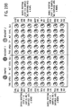
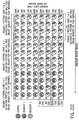
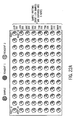
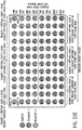
- the product(s) of an immunoassay reaction can be transferred from a first micro-well of a micro-well plate to a second micro-well of the micro-well plate, then from the second micro-well of the micro-well plate to a third micro-well of the micro-well plate, and so forth, up to an eighth micro-well of the micro-well plate, the eight micro-wells being in the same column of the micro-well plate having twelve columns, with eight micro-wells per column. According to this embodiment, twelve immunoassays can be carried out simultaneously.
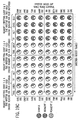
- the products(s) of immunoassay reactions can be transferred from the 96 micro-wells of a first micro-well plate to the 96 micro-wells of a second micro-well plate, then from the 96 micro-wells of the second micro-well plate to the 96 micro-wells of a third micro-well plate, and so forth, up to the 96 micro-wells of an eighth micro-well plate.
- 96 immunoassays can be carried out simultaneously.
- the current ARCHITECT® CMIA (chemiluminescent microparticle immunoassay) protocol can be expanded to utilize 2 ml of sample by harvesting the analyte/antigen across 10 wells having a volume of 200 ⁇ l each.
- the ARCHITECT® CMIA protocol can be expanded to perform a homogeneous protocol by adding reagents without performing separation and wash.
- the method and apparatus described herein can be used to carry out homogeneous assays, because the magnetic particle processing apparatus can be used without a separation step, i.e., the sample and the reagents can merely be mixed, allowed to react, and the separation step used in a heterogeneous assay can merely be eliminated.
- this invention provides a method for carrying out immunoassays and clinical chemistry assays according to claim 4.
- a number of automated protocols can be employed to carry out immunoassays and clinical chemistry assays. These automated protocols include, but are not limited to, such process steps as addition of samples to reactions vessels, addition of reagents to reaction vessels, mixing of the contents of reactions vessels, incubation of reactants in reactions vessels, separating reaction products, and washing reaction products.
- a number of aspirating/dispensing protocols can be employed to carry out immunoassays and clinical chemistry assays. These aspirating/dispensing protocols involve kitting micro-well plates by means of a schedule not constrained by a fixed protocol. Fixed protocols are commonly utilized in conventional automated clinical laboratory analyzers.
- the method of this invention removes limitations upon the order of addition of reagents.
- the kitting protocol is not constrained by limitations relating to addition of reagents. Kitting can be carried out prior to the entry of a micro-well plate into a magnetic particle processing apparatus.
- the protocols eliminate the limitations inherent in the use of a carousel of an automated clinical laboratory analyzer into which conventional sample containers and conventional reagent containers are loaded by an operator. Protocols can be changed with simple updates of software files. Kitting reagents prior to performance of an assay eliminates the requirement for synchronous addition of reagents that is an inherent feature associated with a protocol that requires a device having steps of fixed intervals, such as, for example, a carousel or a process path.
- Devices for aspirating/dispensing can be used for kitting both immunoassays and clinical chemistry assays.
- the aspirating/dispensing protocols enable devices for aspirating/dispensing to be used for dispensing samples and reagents for clinical chemistry assays while immunoassays are being carried out.
- the device for aspirating/dispensing can be used to carry out the step of a clinical chemistry assay, and vice versa.
- This invention provides a novel scheduling system for immunoassays and clinical chemistry assays that enables clinical chemistry assays to be carried out between immunoassays and immunoassays to be carried out between clinical chemistry assays.
- sample containers, reagent containers, and micro-well plates can be lifted, transported, and lowered by a device normally used for aspirating/dispensing.
- Pipettes of the aspirating/dispensing device can be equipped with gripping devices that can grip and transfer sample containers, reagent containers, and micro-well plates from one position to another.
- the gripping devices can be equipped with projections to bring about higher pressure against the sample containers, reagent containers, and micro-well plates.
- surfaces that conform to the cylindrical shape of the container can be adhered to the gripping devices to enable the cylindrical containers to be more readily gripped and transferred from one location to another.
- the method described herein includes a method of reading information from labels.
- radio frequency identification tags conforming to the guidelines of ISO 14443 or ISO 15693 and ISO 18000, are positioned on the items of interest, such as, for example, reagent containers, sample containers, and micro-well plates. These tags can be read by and written to by either a moving antenna of a radio frequency identification reader or a stationary antenna of a radio frequency identification reader. Reading of radio frequency identification tags and writing to radio frequency identification tags are controlled by software.
- the use of radio frequency identification technology provides faster and more reliable readings than do barcodes, and further_eliminates the hazards associated with laser scanning devices.
- the system described herein enables tracking of micro-well plates from the initial dispensing of samples and reagents to the final reading of results from the plates.
- troughs for holding bulk reagents can be employed.
- the use of troughs for holding bulk reagents enables aspirating/dispensing devices having a plurality of pipettes to aspirate and dispense reagents at a high rate of throughput.
- Reagent containers and sample containers can be transferred from a refrigerated storage area to the analysis section of the laboratory automation system by an automated robotic mechanism.
- the laboratory automation system described herein provides a user-friendly graphical user interface for enabling an operator to closely control and monitor numerous immunoassays and/or clinical chemistry assays.
- the graphical user interface can utilize fuel gauge-type liquid level indicators to simplify reading of liquid levels in containers.
- the graphical user interface can utilize instructional balloons to instruct relatively inexperienced operators in proper usage of the laboratory automation system.
- the laboratory automation system and method described herein result in improved sensitivity of assays, reduction of assay processing resources, and improved reliability.
- the laboratory automation system and method described herein improve flexibility of assay processing resources, whereby new assays and new assay protocols can be accommodated with minimal effect upon the design of the laboratory automation system.
- the physical arrangement of the micro-wells in the micro-well plates along with the coloration of the micro-wells in the micro-well plates enables efficient collection of photons when luminescence readers are used.
- the collection of photons is not efficient on account of the geometry of the cuvette and the geometry of the photomultiplier tube.
- Many chemiluminescent readers currently used to read results of immunoassays collect photons from the side of a translucent cuvette. A small portion of the photons emitted from the "sphere of light" enters into a light pipe and eventually arrive at the photomultiplier tube, where they are counted.
- In-track vortexers are vertically movable mixers located underneath the track of a conventional analyzer that utilize fixed interval steps for moving reactions vessels, e.g., a carousel or a process path. After a reagent is dispensed into a reaction vessel, the vertically movable mixers are used to provide mixing of contents within the reaction vessel, typically by means of nutator rotators.
- the apparatus and method described herein greatly simplifies the apparatus and method needed to carry out immunoassays and clinical chemistry assays. Only a single XYZ pipette is required, rather than a plurality of pipettes. By dispensing samples in rows and reagents in columns of a micro-well plate, or vice versa, pipettes can dispense a plurality of aliquots of samples or a plurality of aliquots of reagents without the need for filling the pipette until all of the aliquots are dispensed, thereby both reducing the time needed to move a pipette to and from a sample container and the time needed to move a pipette to and from a reagent container.
- Process path diverters which are used in some automated clinical laboratory analyzers, are not required. Fewer mechanical parts are required to process reactions carried out in micro-wells of micro-well plates, thereby improving the reliability of the laboratory automation system. Positive displacement pumps that are actuated by a stepper motor for dispensing controlled amounts of liquids are not required. Conventional analyzers use positive displacement pumps for washing tips of probes and directly dispensing diluents, wash buffer, and pre-trigger solutions.
- the apparatus and method described herein enable immunoassays to be integrated with clinical chemistry assays, using many of the same resources, such as, for example, pipettes, kitting stations, fluidics, refrigeration equipment, controllers, power supply, capable of being used for both types of assays.
- Other types of assay formats such as, for example, fluorescent polarization immunoassay (FPIA) format can be added to the laboratory automation system.
- FPIA fluorescent polarization immunoassay
- the apparatus and method described herein also enable extraction of nucleic acids from a biological sample and amplification of the nucleic acids thus extracted to be integrated with immunoassays and clinical chemistry assays, using many of the same resources, such as, for example, pipettes, kitting stations, fluidics, refrigeration equipment, controllers, power supply, capable of being used for all three types of assays.
- Micro-well plates can be tracked by means of radio frequency identification, while conventional reaction vessels cannot be so tracked. Many commercially available sub-systems are available to process micro-well plates, which allows the user to incorporate improvements, delay obsolescence, transfer accounts for vendors who go out of business.
- the term "immunoassay” means a biochemical test that measures the concentration of a substance in a biological liquid, typically serum, using the reaction of an antibody or antibodies to its (their) antigen.
- An immunoassay takes advantage of the specific binding of an antibody to its antigen.
- a “chemiluminescent microparticle immunoassay” alternatively referred to as “chemiluminescent magnetic immunoassay” involves a chemiluminescent label conjugated to the antibody or the antigen.
- a magnetic microparticle is coated with antibodies. The assay is intended to look for antigens in the sample.
- a second antibody is labeled with a chemiluminescent label.
- This second antibody is not attached to a magnetic microparticle.
- the magnetic microparticle is then washed off.
- the amount of antibody-antigen-enzyme is measured by adding pre-trigger solution and trigger solution and measuring the light produced.
- This type of immunoassay produces light when combined with its substrate, i.e., a specific binding member.
- the chemiluminescent reaction offers high sensitivity and ease of measurement.
- This type of immunoassay involves a noncompetitive sandwich format that yields results that are directly proportional to the amount of analyte present in the sample.
- the term "magnetic" means paramagnetic.
- the expression "clinical chemistry assay” means a biochemical test that measures the concentration of a substance that occurs naturally within the human body, which concentrations serves to indicate the condition or state of health of the various systems of the body. Such a substance, often referred to as an analyte, exists within certain expected ranges of concentration in a healthy human being.
- Chemical analytes fall into one of three main categories, routine analytes, such as for example, lipids, nutrients, chemical constituents, metabolic products, examples of which include glucose, urea nitrogen triglycerides, uric acid, enzymes, such as, for example, alanine aminotransferase, aspartate aminotransferase, lactate dehydrogenase, and amylase, and electrolytes, such as, for example, sodium, potassium, and chloride.
- routine analytes such as for example, lipids, nutrients, chemical constituents, metabolic products, examples of which include glucose, urea nitrogen triglycerides, uric acid, enzymes, such as, for example, alanine aminotransferase, aspartate aminotransferase, lactate dehydrogenase, and amylase
- electrolytes such as, for example, sodium, potassium, and chloride.
- the expression "laboratory automation system” means a system designed to automate the processing of samples prior
- sample means a material suspected of containing an analyte.
- the sample can be used directly as obtained from the source in an assay or following a pretreatment to modify the character of the sample before undergoing an assay.
- the sample can be derived from any biological source, such as, for example, a physiological fluid, including, but not limited to, blood, saliva, ocular lens fluid, cerebral spinal fluid, sweat, urine, milk, ascites fluid, mucous, synovial fluid, peritoneal fluid, amniotic fluid, or the like.
- the sample can be pretreated prior to use, such as, for example, preparing plasma from blood, diluting viscous fluids, or the like.
- Methods of pretreatment can involve filtration, distillation, concentration, inactivation of interfering components, and the addition of reagents.
- physiological fluids other liquid samples can be used, such as, for example, water, food products, and the like.
- a solid material suspected of containing the analyte can be used as the sample.
- analyte refers to the compound or composition to be detected or measured.
- radio frequency identification is a generic term for technologies that use radio waves to automatically identify objects, such as, for example, containers for biological samples and containers for reagents for analyzing biological samples.
- the most common method of identification is to store a serial number that identifies the object, and perhaps other information relating to the object or contents thereof, on a microchip that is attached to an antenna.
- the microchip and the antenna together are called a radio frequency identification transponder or a radio frequency identification tag.
- the antenna enables the microchip to transmit the identification information and other information to a radio frequency identification reader.
- the radio frequency identification reader converts the radio waves reflected back from the radio frequency identification tag into digital information that can then be passed on to computers that can make use of It.
- the expression "aspirating/dispensing device” means a device that has the dual functions of removing liquids from containers by suction and distributing portions of the liquids aspirated into containers, e.g., micro-wells of micro-well plates.
- An aspiration/dispensing device that is capable of being used for the system described herein is described in U. S. Patent No. 7,033,543 .
- the term “pipette”, also called “pipet”, “pipettor” means a laboratory instrument used to transport a measured volume of liquid.
- micro-well plate also called “microtiter plate”, “microplate” means a flat plate having a plurality of "wells” used as small test tubes.
- XYZ refers to a device that can move in three directions, a first horizontal direction, a second horizontal direction that is perpendicular to the first horizontal direction, and a third direction that is perpendicular to both the first horizontal direction and the second horizontal direction.
- re-use refers to a disposable item that can be used again rather than disposed of a after a single_use.
- the term "fixed protocol” means a protocol for carrying out an assay, wherein the beginning and ending times assigned for the incubation step(s), the beginning and ending times assigned for the mixing step(s), the beginning and ending times assigned for the reagent addition step(s), the beginning and ending times assigned for the washing step(s), and the like for other step(s), must occur at a fixed time after the assay has commenced.
- the expression "analysis section of the laboratory automation system” means that portion of the laboratory automation system in which immunoassays or clinical chemistry assays or both immunoassays and clinical chemistry assays are performed.
- kitting means dispensing samples and reagents in appropriate micro-wells of a micro-well plate prior to commencing chemical reactions.
- the expression “extraction of nucleic acid(s)” and the like means removal of nucleic acid(s) from a biological sample.
- the expression “amplification of nucleic acid(s)”, and the like refers to assays that use purified enzymes to isolate and then replicate specific nucleic acid(s) to levels it (they) can be detected.
- An example of a technique for amplification of nucleic acid(s) is polymerase chain reaction (PCR).
- PCR polymerase chain reaction
- multi-well plate means a plastic tray having an upper surface and a lower surface and a plurality wells depending from the lower surface of the tray, the wells capable of being filled through openings in the upper surface of the tray.
- the wells can be limited in size to contain a relatively small amount of liquid, e.g., less than one mL, and the multi-well plates containing the same are designated as micro-well plates.
- the wells can be expanded in size to contain a relatively large amount of liquid, e.g., greater than one mL, and the multi-well plates containing the same are merely designated as multi-well plates.
- the symbol “(s)” following the name of an item indicates that one or more of the subject items is intended, depending upon the context.
- the expression “and/or” is used to indicate that either the word “and” or the word “or” can be used to connect words, phrases, or clauses.
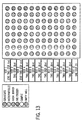
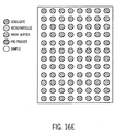
- micro-well plate(s) is indicated by the letter "P". It should be noted the micro-well plates in processors and readers are not actually visible. However, the micro-well plates are inside of the processors and readers and the relative positions of the micro-well plates within the processors and readers are designated by the letter P.
- Laboratory automation systems typically employ aspirating/dispensing devices wherein a pipette (or pipettes) of the aspirating/dispensing device can be moved in three dimensions, i.e., two dimensions in a horizontal plane (i.e., X and Y) and one dimension vertically (i.e., Z).
- the remaining components of laboratory automation systems can be placed near to or be connected with the aspirating/dispensing device to enable the pipette (or pipettes) to obtain access to various components of the laboratory automation system.
- not all components require direct access from an aspiration/dispensing device.
- micro-well plates into which reagents have been dispensed can be moved out of the access range of the aspiration/dispensing device by an optional robotic mechanism and placed in an autonomous subsystem for further processing.
- chemiluminescent microparticle immunoassays do not call for dispensing reagents after kitting has taken place.
- clinical chemistry assays require dispensing reagents between readings.
- laboratory automation sub-systems e.g., various diagnostic assay technologies
- multiple sub-systems can be added to the laboratory automation system to increase throughput, e.g., one or more immunoassay sub-systems can be added to an immunoassay sub-system to increase throughput of immunoassays, or one or more clinical chemistry assay sub-systems can be added to a clinical chemistry assay sub-system to increase throughput of clinical chemistry assays.
- FIG. 1 illustrates a laboratory automation system that can be modified for use with the system and method described herein.
- a track arrangement for enabling the movement of containers containing samples (sample containers) and containers containing reagents (reagent containers) from an input/output module to one or more short-term storage areas for reagent containers and sample containers.
- reagent containers containers containing reagents
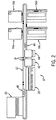
- FIG. 2 illustrates other conventional components of a laboratory automation system that can be placed around the track arrangement.
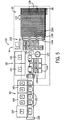
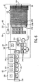
- FIGS. 5 , 6 , and 7 illustrate three of several possible ways of arranging the components of the analysis section of the laboratory automation system, but not including the track system, which can be used with any of the arrangements shown in FIGS. 5 , 6 , and 7 .
- FIGS. 5 , 6 , and 7 illustrate three of several possible ways of arranging the components of the analysis section of the laboratory automation system, but not including the track system, which can be used with any of the arrangements shown in FIGS. 5 , 6 , and 7 .
- FIGS. 5 , 6 , and 7 illustrate three of several possible ways of arranging the components of the analysis section of the laboratory automation system, but not including the track system, which can be used with any of the arrangements shown in FIGS. 5 , 6 , and 7 .
- FIGS. 5 , 6 , and 7 illustrate three of several possible ways of arranging the components of the analysis section of the laboratory automation system, but not including the track system, which can be used with any of the arrangements shown in FIGS. 5 , 6 ,
- 5 , 6 , and 7 show the relative positions of such components as aspirating/dispensing devices, signal detectors, such as, for example, readers, e.g., an absorbance reader, a luminescence reader, an immunoassay processor, e.g., a chemiluminescent microparticle immunoassay (CMIA) processor, a clinical chemistry assay (CC) processor, a micro-well plate rotator, positions for storage of disposable components, positions for storage of reagents, and positions for storage of samples.
- CMIA chemiluminescent microparticle immunoassay
- CC clinical chemistry assay
- FIG. 1 shows a sub-system, i.e., an analysis section of a laboratory automation system, wherein immunoassays are integrated with clinical chemistry assays.
- This sub-system can also perform a relatively high number of assays per unit of time.
- This same sub-system is shown in FIG. 5 .
- This sub-system enables a throughput of about 192 immunoassay tests per hour (when no clinical chemistry tests are run) or 900 clinical chemistry tests per hour (when no immunoassay tests are run) or 600 clinical chemistry tests per hour and 96 immunoassay tests per hour when both types of tests are run together.
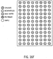
- FIG. 6 shows a sub-system, i.e., an analysis section of a laboratory automation system, similar to that shown in FIGS.
- FIG. 6 shows a sub-system, I.e., an analysis section of a laboratory automation system, wherein only immunoassays are carried out. However, this sub-system can perform a very high number of immunoassays per unit of time. This sub-system enables a throughput of immunoassays of about 1200 immunoassay tests per hour. Other sub-systems can be manufactured.
- certain variations of the sub-systems shown in FIGS. 1 , 5 , and 6 can delete the immunoassay components.
- certain variations of the sub-systems shown in FIGS. 1 , 5 , and 6 can delete the clinical chemistry components.
- a laboratory automation system 10 comprises a track system 12.
- the track system 12 has a first lane 14 and a second lane 16.
- the purpose of the first lane 14 is to transport a container holding a sample (i.e., a sample container) 18 from an input/output module 20 (see FIG. 2 ) to a sample container queue 22.
- a sample container 18 can suitably travel over the track system 12 by means of a sample container carrier 24 (see FIGS. 3A and 3B ).
- Sample container carriers 24 suitable for transporting sample containers 18 on a lane of a track system are commercially available from suppliers such as, for example, Inpeco S. p.
- sample container carrier 24 is described, for example, in U, S. Patent Nos. 5,417,922 ; 5,427,743 ; 5,589,137 ; and 6,343,690 .
- the sample containers 18 can be placed in sample container carriers 24 by means of a suitable robotic mechanism (not shown).
- the sample container carriers 24 travel along the first lane 14 of the track system 12 by means of an endless conveyor belt, or a suitable alternative thereto.
- Such conveyor belts, and suitable alternatives thereto are well known to those having ordinary skill in the art.
- the sample container 18 or adapter sleeve 28 can be equipped with a radio frequency identification tag 26, which can be used to identify and track a given sample container 18.
- the sample container carrier 24 can be equipped with adapter sleeves 28, which enable the sample container carriers 24 to be the same size as reagent container carriers 34 to adapt to sample containers 18 having differing diameters or differing lengths or both of the foregoing.
- the purpose of the second lane 16 is to transport a container holding a reagent (i.e., a reagent container) 30 from the input/output module 20 to a reagent container queue 32.
- a reagent container 30 can suitably travel over the track system 12 by means of a reagent container carrier 34 (see FIG. 4 ).
- a representative example of a reagent container carrier 34 suitable for this purpose is commercially available from Nittobo Boseki Co., Ltd. and Rexam PLC. Such a reagent container carrier 34 is described, for example, in U. S. Patent Nos. 6,074,615 and 6,555,062 .
- the reagent containers 30 can be placed in reagent container carriers 34 by means of a suitable robotic mechanism (not shown).
- the reagent container carriers 34 travel along the second lane 16 of the track system 12 by means of an endless conveyor belt, or a suitable alternative thereto. Such conveyor belts, and suitable alternatives thereto, are well known to those having ordinary skill In the art.
- the reagent container 30 can be equipped with a radio frequency Identification tag 36, which can be used to Identify and track a given reagent container 30. It is also possible to use the same lane of the track system 12 to transport sample container carriers 24 and reagent container carriers 34, as well as to use separate lanes for the sample container carriers 24 and the reagent container carriers 34. The use of the same lane for both sample container carriers 24 and reagent container carriers 34 could reduce the cost of the track system 12. In addition, the use of the same lane for both sample container carriers 24 and reagent container carriers 34 allows sample container carriers 24 and reagent container carriers 34 to be of the same size.
- a system for managing the inventory of reagents can be designed to place reagent containers 30 into reagent container carriers 34, after which placement, these reagent container carriers 34 will be routed to the analysis section of the laboratory automation system 10, where they will be diverted into the correct local queue 32.
- Such placement can be effected by a robotic mechanism (not shown), which will have the capability of picking up a reagent container 30 from a storage location near the track system 12 and placing the reagent container 30 on a reagent container carrier 34.
- a system for providing the samples can be designed to place sample containers 18 into sample container carriers 24 or reagent container carriers 34 having adapter sleeves 28, after which placement, these sample container carriers 24 will be routed to the analysis section of the laboratory automation system 10, where they will be diverted into the correct local queue 22.
- Such placement can be effected by a robotic mechanism (not shown), which will have the capability of picking up a sample container 18 from a storage location near the track system 12 and placing the sample container 18 on a sample container carrier 24 or a reagent container carrier 34 having an adapter sleeve 28.
- Each analysis section of the laboratory automation system 10 will have local queues 22, 32, where the sample container carriers 24 and the reagent container carriers 34, respectively, are diverted from the track system 12 and held for processing.
- Diverters suitable for such a diverting purpose are well-known to those of ordinary skill in the art.
- a diverter is typically an electromechanically actuated gate.
- An example of a diverter suitable for use herein is described in U. S. Patent No. 6,202,829 .
- the reagent containers 30 are merely removed from the reagent container carriers 34 and placed in the reagent storage area located within the analysis section of the laboratory automation system 10.
- the samples are aspirated from a sample container 18, which need not be removed from the sample container carrier 24.
- the samples can be aspirated from a given sample container 18 until all of the samples required for a testing of that sample have been removed from the sample container 18.
- the sample container carriers 24 and the reagent container carriers 34 are released from the local queue(s) 22, 32, and are transported to the track system 12.
- Empty reagent containers 30 are disposed of in solid waste containers.
- the sample containers 18 can be held In the sample container carrier 24 until results and/or orders determine that no retest or additional testing is required.
- the reagent container carriers 34 can simply be recycled for the next reagent transporting operation.
- a reagent inventory management system can be added to the laboratory automation system 10 described herein.
- a typical reagent inventory management system includes an operator interface for the loading of boxes of reagents and other supplies, radio frequency identification system for identification of inventory and tracking, robotic mechanisms for loading containers onto the track system and removing containers from the track system, decapping equipment, refrigeration equipment, and information technology connections to laboratory analyzers and vendors.
- a sample container tray 38 that supports a plurality of sample containers 18 can be used.
- the laboratory automation system 10 would merely have the queues for the reagent container carriers 34 and the sample container carriers 24 replaced by a suitable support for the sample container trays 38. See, for example, FIGS. 5 , 6 , and 7 .
- the track system 12 is not shown. In place of the track system 12 are sample container trays 38. However, fittings for sample container trays 38 can be removed, and the remainder of the laboratory automation system 10 can be connected with a track system 12.
- FIG. 2 which is a commercially available laboratory automation system 10', such components that can also be used in the laboratory automation 10 described herein are positioned along the track system 12'. These components include, but are not limited to, the input/output module 20 for (a) introducing sample containers 18 to the laboratory automation system 10 and (b) removing sample containers 18 from the laboratory automation system 10, and a container storage and retrieval unit 40 for storing samples upon which a set of assays has been performed. Also shown in FIG.
- a first centrifuge system 42 and a second centrifuge system 44 for separating serum from cells in a sample of blood
- a decapper 46 for removing caps from sample containers 18, typically caps from sample tubes
- a resealer 48 for sealing the sample containers 18 after completion of analytical testing
- a refrigerator (not shown) for prolonging the useful life of biological materials, e.g., reagents, samples.
- the reagent containers 30 can be loaded by the operator into the refrigerator, when the reagent containers 30 are received in a shipping carton from a shipping department. This loading process may require removing the top of the shipping carton.
- the radio frequency identification tags 36 affixed to the reagent containers 30 can be read by a radio frequency identification reader (not shown) associated with the refrigerator and the inventory is recorded.
- a radio frequency identification reader (not shown) associated with the refrigerator and the inventory is recorded.
- the system for managing the inventory of reagents typically removes the oldest reagent(s) of the type requested from a shipping carton in the refrigerator, i.e., in a first-in, first-out manner, prepares the reagent container(s) 30 for processing (e.g., caps are removed, septa are installed, etc.) and places the reagent container(s) 30 into reagent container carrier(s) 34.
- Removal of the reagent container 30 from the shipping carton and placement of the reagent container 30 into the reagent container carrier 34 can be carried out by means of a robotic mechanism (not shown).
- the reagent container carriers 34 holding the reagent containers 30 are then diverted onto the appropriate lane of the track system 12 and subsequently routed to the analysis section of the laboratory automation system 10 that requested the reagent(s).
- empty shipping cartons are ejected from the refrigerator into a solid waste container.
- control unit for handling information in the laboratory automation system 10.
- the control unit also provides the commands to the various robotic mechanisms, which carry out the automated functions of the laboratory automation system 10. It is expected that the control unit can be a personal computer. Additional discussion of the conventional components of a simple laboratory automation system can be found in Ikeda et al., "Total Clinical Laboratory Testing System for Laboratory Automation", Hitachi Review, Vol. 41 (1992) No. 4, pages 167-172 . Examples of tube storage and retrieval units, input/output modules, centrifuge systems, decappers, resealers, refrigerators, and other auxiliary components are well-known to those of ordinary skill in the art and are readily commercially available from numerous sources. Also shown in FIG.
- first Immunoassay analyzer 50a a first Immunoassay analyzer 50a
- second immunoassay analyzer 50b a first clinical chemistry analyzer 50c
- second clinical chemistry analyzer 50d a second clinical chemistry analyzer 50d.
- the invention described herein utilizes different types of immunoassay analyzers and different types of clinical chemistry analyzers,
- a central reagent storage area (not shown) can provide a substantial inventory of reagents; these reagents can be transported to the track system 12 or the analysis section of the laboratory automation system 10 as required.
- Means of transportation suitable for transporting reagents from the central storage area to the input/output module 20 include, but are not limited to, gantries, endless conveyor belts, and robotic mechanisms.
- Adjacent to the track system 12 is at least one analysis section 60 of the laboratory automation system 10. Depending upon the size of the track system 12, more than one analysis section 60 can be employed.
- the analysis section 60 has four major sub-sections, namely a sub-section 62 for retaining samples and reagents that are to be used in the assays, a sub-section 64 for retaining disposable components for the equipment needed to introduce and manipulate samples and reagents into reaction vessels, e.g., micro-well plates, a sub-section 66 for supporting instruments needed to carry out immunoassays, and a sub-section 68 for supporting instruments needed to carry out clinical chemistry assays.
- Sub-section 66 is not required to be directly accessible to an aspiration/dispensing device and can utilize kitted micro-well plates.
- Sub-section 68 generally requires an aspiration/device that has direct access to micro-well plates.
- the sub-section 62 of the analysis section 60 is preferably elevated to a level sufficient to accommodate a radio frequency identification reader (not shown) for reading information from radio frequency identification tags 26, 36.
- a radio frequency identification reader is described in U. S. Application Serial No. 11/495,430, filed July 28, 2006 , entitled SYSTEM FOR TRACKING VESSELS IN AUTOMATED LABORATORY ANALYZERS BY RADIO FREQUENCY IDENTIFICATION.
- the radio frequency identification system includes at least one movable radio frequency identification reader.
- the radio frequency Identification reader In order for the radio frequency Identification reader to read the data from the radio frequency identification tag associated with a container, or with a container carrier, the radio frequency identification reader is caused to move to a position proximate to the radio frequency identification tag so that the information from the radio frequency identification tag can be read with an amount of noise and interference from nearby radio frequency identification tags on other containers, or on other container carriers, that are insufficient to adversely affect the integrity of the data read by a radio frequency identification reader.
- a transmission sub-system must be provided to enable the at least one radio frequency identification reader to move among the containers and the carriers for the containers.
- a second reader which is stationary, can be used to read the radio frequency identification tags attached to consumable items that are transported to the vicinity of the second reader.
- the radio frequency identification system includes at least one stationary radio frequency identification reader.
- the container, or the container carrier In order for the at least one radio frequency identification reader to read the data from the radio frequency identification tag associated with a container, or with a container carrier, the container, or the container carrier, is caused to move to a position proximate to, and preferably in register with, the at least one radio frequency identification reader so that the information from the radio frequency identification tag can be read with an amount of noise and interference from nearby radio frequency identification tags on other containers, or on other container carriers, that are insufficient to adversely affect the integrity of the data read by a radio frequency identification reader.
- a transmission sub-system need not be provided to enable the at least one radio frequency identification reader to move among the containers and the container carriers.
- the sample containers and the reagent containers, or the sample container carriers and the reagent container carriers can be transported to a position proximate to at least one stationary radio frequency identification reader, whereby the stationary radio frequency identification reader tags on the containers, or on the container carriers, can be read by the at least one stationary radio frequency identification reader.
- a plurality of antennas which are traces on a printed circuit board, function as separate stationary radio frequency identification readers. These antennas can receive separate collections of data.
- a single printed circuit board has a plurality of antennas under the reagent storage area and the sample storage area.
- the length of the antenna is important, because the length determines the relationship with the radio frequency used.
- the length of the antenna corresponds to some multiple of wavelength of the radio frequency energy, e.g., one-half wavelength, one-quarter wavelength.
- the printed circuit board for the radio frequency identification system can provide connections for remote antennas and a means for selecting those antennas one at a time.
- the radio frequency identification system can have external connections for several remote reading locations, such as the micro-well plate rotator, pre-treatment area, magnetic particle processor, luminescence reader(s), absorbance reader(s), inventory reading locations, and locations on the local queue and transport track. By reading the antennas at these remote locations, a micro-well plate can be tracked throughout the laboratory automation system and provide a chain of custody.
- a radio frequency identification tag can be positioned on the lowermost portion of a container, e.g., a reagent container 30, or on a container carrier, e.g., a sample container carrier 24. It is often desirable to position an encapsulated radio frequency identification tag on the lowermost portion of a container. In the case of sample containers 18, a radio frequency identification tag can be positioned on the sample container carrier 24.
- two high frequency (13.56 MHZ) radio frequency identification readers can be employed.
- One radio frequency identification reader is capable of moving under the area where the reagent containers are positioned.
- the other radio frequency identification reader which is stationary, reads radio frequency identification tags on micro-well plates.
- the use of radio frequency identification readers makes it possible to efficiently and tightly pack reagent containers and sample containers 18 in the laboratory automation system 10.
- the use of radio frequency identification readers and radio frequency identification tags make it possible to include a higher density of data on a container, relative to the amount of data that can be applied by means of barcodes.
- the data on the radio frequency identification tags can be updated to reflect changes that have taken place with respect to the contents of the containers equipped with the radio frequency identification tags.
- the radio frequency identification system can provide an interface to personal computer.
- samples are shared for both immunoassay and clinical chemistry assay technologies.
- the samples can be transported to the sub-section 62 of the analysis section 60 by the track system 12 of the laboratory automation system 10 to minimize the storage of samples on the analysis section 60 of the laboratory automation system 10 and to automate retest and/or reflex testing.
- the samples can be positioned at the sub-section 62 of the analysis section 60 by other means, such as, for example, manually or, if desired, by a robotic mechanism (not shown).
- samples can be transferred to the analysis section 60 of the laboratory automation system 10 by means of a sample container carrier 24 or by means of trays 38 that support sample containers 18.
- a typical sample container tray 38 can hold up to five (5) sample containers 18, a row of sample container trays can typically comprise up to three (3) sample container trays 38, and the sub-section 62 can typically hold up to twelve (12) sample container trays. While the area of the sub-section 62 of the analysis section 60 allocated for sample containers 18 is not critical, it can be seen that up to sixty (60) sample containers 18 can be stored in the sub-section 62. However, more than sixty sample containers 18 can be stored in sub-section 62 of the analysis section 60, if the dimensions of the analysis section 60 are increased.
- the sub-section 62 of the analysis section 60 provides sufficient space for temporary storage for reagent containers 30 for clinical chemistry assays, temporary storage of reagent containers 30 for immunoassays, along with equipment for stirring reagents for immunoassays, and temporary storage of sample containers 18.
- the sub-section 62 can be designed to include reagent containers 30 for clinical chemistry assays only, reagent containers 30 for immunoassays only, or a combination of reagent containers 30 for both types of assays.
- the sub-section 62 is preferably equipped to provide refrigeration and evaporation control for the reagents and the samples.
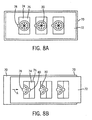
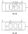
- FIGS. 8A, 8B , 8C, and 8D illustrate a system for minimizing the exposure of reagent containers 30 to the environment.
- a system of sliding reagent covers 70, 72 can be used to insulate the reagent containers 30 from the exterior environment. Reagents can be preserved for longer periods of time through the use of the sliding reagent cover embodiment described herein.
- a first sliding reagent cover 70 is positioned above a plurality of reagent containers 30 located in the sub-section 62.
- a second sliding reagent cover 72 is positioned above the plurality of reagent containers 30 and also above the first sliding reagent cover 70.
- the first sliding reagent cover 70 is substantially rectangular in shape, as is the second sliding reagent cover 72.
- the first sliding reagent cover 70 is inserted into a track (not shown) in which the first sliding reagent cover 70 can slide in a horizontal direction, as shown by the arrow "A".
- the second sliding reagent cover 72 is inserted into a track (not shown), which is in register with the track into which the first sliding reagent cover 70 is inserted, in which the second sliding reagent cover 72 can slide in a horizontal direction, as shown by the arrow "A”.
- the first sliding reagent cover 70 has a plurality of openings 74 formed therein, which can be placed in register with a plurality of reagent containers 30.
- the second sliding reagent cover 72 has a plurality of openings 76 formed therein, which can be placed in register with a plurality of reagent containers 30.
- the openings 74 and the openings 76 are rectangular in shape.
- This semi-circular notch 78 has its open portion facing the right.
- At the right edge of each opening 74 in the first sliding reagent cover 70 is a semi-circular notch 80.
- This semi-circular notch 80 has its open portion facing the left.
- the first sliding reagent cover 70 and the second sliding reagent cover 72 can be moved relative to one another so that the notches 80 in the first sliding reagent cover 70 and the notches 78 in the second sliding reagent cover 72 join to form a small opening, through which the tip of a pipette can be inserted to aspirate a liquid reagent from a reagent container 30.
- the first sliding reagent cover 70 and the second sliding reagent cover 72 can be moved relative to one another so that the small opening is closed, thereby enabling the first sliding reagent cover 70 and the second sliding reagent cover 72 to reduce the effect of the environment on the reagents, thereby resulting in a longer useful life for the reagent.
- the individual reagent containers 30 for clinical chemistry assays and the individual reagent containers 30 for immunoassays can be removed from reagent container carriers 34, inserted at the appropriate locations of sub-section 62 of the analysis section 60 by means of a robotic system, wherein gripping devices 92 can be affixed to a device 94 that can aspirate and dispense liquids, hereinafter alternatively referred to as an aspirating/dispensing device 94. See FIGS. 9A, 9B , 9C, 9D , 9E, and 9F for schematic diagrams illustrating gripping devices suitable for use herein.
- the aspirating/dispensing device 94 is capable of aspirating liquids from a container and dispensing liquids into a micro-well of a micro-well plate,
- the aspirating/dispensing device 94 has a head 96 that can be equipped with a plurality of pipettes 98.
- a commercially available robotic system suitable for use herein typically has from four to twelve pipettes.
- the gripping devices 92 are capable of gripping reagent containers 30, sample containers 18, and micro-well plates, raising the gripped container or the gripped micro-well plate in a vertical direction, and lowering the gripped container or the gripped micro-well plate in a vertical direction.
- the aspirating /dispensing device 94 is capable of moving in the two horizontal directions that are perpendicular to one another.
- the range of movement in either direction is unlimited. However, for the sake of economics, it is preferred that the analysis sections be as small as possible. Accordingly, It is expected that a typical range of movement for the aspirating/dispensing device 94 be from about two feet to about eight feet, preferably from about two feet to about six feet, more preferably from about two feet to about four feet in both horizontal directions.
- a robotic system suitable for use with the apparatus and method described herein is commercially available from Hamilton Company. In this system, two pipettes 98 of the aspirating/dispensing device 94 are capable of receiving the gripping devices 92.
- the gripping devices 92 can be securely attached to the stems of the pipettes 98 of the aspirating/dispensing device 94 by means of an expandable O-ring locking mechanism.
- the expandable O-ring locking mechanism is described in U. S. Patent No. 7,033,543 .
- the gripping devices 92 are typically rectangular parallelepipeds, e.g., in the shape of paddles, and are typically made of metal, e.g., stainless steel.
- FIGS. 9A and 9B illustrate gripping devices 92 that are suitable for gripping micro-well plates.
- Each paddle-shaped gripping device 92 has at least one projection, preferably two or more projections, on the major surface thereof that contacts the edge of a micro-well plate.
- This same expandable O-ring can be used to retain a pipette tip, which can be slipped over the discharging end of a pipette 98.
- This expandable O-ring mechanism holds the pipette tip securely, while the pipette is being used to aspirate and dispense fluids and even when the pipette tip is penetrating the septum of a container, which activity would typically cause a friction-staked pipette tip to be pulled off the discharging end of the pipette.
- the micro-well plate In order for the aspirating/dispensing device 94 to grip a micro-well plate, two pipettes of the aspirating/dispensing device 94 to which the gripping devices 92 are attached are moved toward each other, whereby the micro-well plate can be gripped between the paddle-shaped gripping devices 92.
- the micro-well plate When being gripped, the micro-well plate can be either in the portrait or landscape orientation, i.e., the micro-well plate can be gripped via either the two longer sides of the micro-well plate or by the two shorter sides of the micro-well plate.
- the gripping devices 92 can be used for gripping cylindrical-shaped containers, such as, for example, reagent containers 30, sample containers 18.
- the gripping devices 92 are preferably rectangular parallelepipeds, as shown and described previously, to which are attached adapters 92a of such a size and shape that the adapters 92a can substantially conform to the shape of the container.
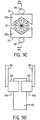
- FIGS. 9C and 9D illustrate gripping devices 92 that are suitable for gripping cylindrical-shaped containers.
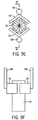
- Another embodiment of a gripping device 92 that carries out the same function as the gripping device 92 illustrated in FIGS. 9C and 9D is the gripping device 92 illustrated in FIGS. 9E and 9F .
- FIGS. 9E and 9F In the gripping device 92 illustrated in FIGS.
- the paddles instead of being straight, are substantially L-shaped.
- a pipette 98 equipped with the L-shaped gripping device 92 can readily grip, lift, transfer, lower, and place cylindrical containers 30 from any location to any other location in the analysis section 60 of the laboratory automation system 10.
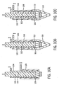
- FIGS. 10A, 10B, 10C , 10D, and 10E illustrate the operation of the expandable O-ring locking mechanism.
- the pipette 98 comprises a cylindrical tube having an interior wall 100 and an exterior wall 102. Encircling a significant portion of the exterior wall 102 of the pipette 98 is an O-ring actuator sleeve 104.
- An expandable O-ring 106 is positioned around the exterior wall 102 of the pipette 98 and immediately below the lower end of the O-ring actuator sleeve 104.
- the expandable O-ring 106 is typically made from a resilient polymeric material.
- Encircling a significant portion of the O-ring actuator sleeve 104 is an ejector sleeve 108.
- FIG. 10A, 10B, 10C , 10D, and 10E illustrate the operation of the expandable O-ring locking mechanism.
- FIG. 10A neither a gripping device 92 nor a pipette tip 110 is mounted to the pipette 98.
- FIG. 10B either a gripping device 92 or a pipette tip 110 is mounted to the pipette 98 by means of a slip fit, wherein there is little or no insertion force.
- FIG. 10C the expandable O-ring 106 is compressed and expanded by means of the O-ring actuator sleeve 104, which is moved vertically by a small motor (not shown).
- a small motor not shown
- the gripping device 92 or the pipette tip 110 is locked onto the cylindrical tube of the pipette 98 via the expandable O-ring 106 and a groove 112 in the interior wall of the pipette tip 110.
- the expandable O-ring 106 is decompressed and retracted radially by raising the O-ring actuator sleeve 104, by reversing the direction of the aforementioned motor.
- the gripping device 92 or the pipette tip 110 is removed for disposal or reuse by means of the ejector sleeve 108, which is moved relative to the main tube of the pipette by a small motor (not shown).
- robotic mechanisms for gripping micro-well plates can also be employed.
- the robotic mechanism can grip a micro-well plate, raise and lower the micro-well plate vertically, and rotate the micro-well plate while it is being transported.
- This type of robotic mechanism while useful for such operations as rotating micro-well plates to facilitate insertion of the plates into various types of assay processors and readers of results of assays, moves micro-well plates above the deck of the laboratory automation system 10 only. It should be noted that in FIGS. 1 , 5 , 6 , and 7 , the components shown therein are positioned on only a single level.
- Another alternative embodiment of robotic mechanism in addition to exhibiting all of the features of the previously mentioned embodiments, is further capable of transporting micro-well plates from a position above the deck of the laboratory automation system 10 to a position below the deck of the laboratory automation system 10, thereby providing another option for transporting micro-well plates from the pipette, then to an assay processor, then to a reader, and finally to a container for waste.
- This embodiment provides an alternative to three-dimensional transport in a limited vertical space. This embodiment will be described in greater detail following the discussion of FIG. 23 .
- a pipette such as a Hamilton pipette
- a pipette eliminates pumps and lines by using dry air displacement syringes.
- Such a pipette provides asymmetric pipette spread for more efficient dispensing of liquids.
- An asymmetric pipette spread means that the dispensing of liquids can be carried out from variable locations, i.e., the pipettes need not be spaced equidistant from one another.
- such a pipette provides capacitative and pressure liquid level sense along with pressure monitoring during aspirating and dispensing.
- the use of expandable O-rings also eliminates the necessity of mounting pipette tips by means of frictional force, which frictional force typically results in the deformation of the pipette tips.
- the reagent containers 30 are preferably contained in a refrigerated area, e.g., an area where the temperature can range from about 2 °C to about 8 °C.
- the reagent containers 30, as well as the sample containers 18 or adapter sleeves 28 for sample containers 18, can be equipped with radio frequency identification tags, which can be read by an automated radio frequency identification reader (not shown) positioned below the sub-section 62 of the analysis section 60.
- a radio frequency identification reader can read and update radio frequency identification tags on reagent containers 30 and on sample containers 18 (or on sample container carriers 24) when aspiration of a portion of the reagent or a portion of the sample is carried out or an operation for scanning the items in inventory is initiated.
- TABLE 1 Class of data Specific data Tag identifier Unique identifier for container Manufacturing data (a) Revision number(s) of reagent(s) (b) Serial number(s) of reagent(s) (d) Component Identifier(s) (e) Lot number(s) of reagent(s) (f) Stability/expiration data for reagent(s) (g) Times/dates of manufacture of reagent(s) (h) Configuration(s) of assay(s) (e.g., number of reagent containers needed) (i) Number of tests in container(s) (j) Associated components of assay(s) (k) Calibration data for assay(s) Shipping and storage data (a) Temperature(s) of reagent during shipping (b) Times/dates of shipping movements and storage periods (c) Locations and dates of storage periods Analyzer and usage data (a) Times/dates of opening
- An area located in front of the analysis section 60 can be used as a radio frequency identification read zone for micro-well plates.
- a system for utilizing radio frequency identification tags and radio frequency identification readers is described in U. S. Application Serial No. 11/495,430, filed July 28, 2006 .
- the sub-section 62 of the analysis section 60 can typically accommodate thirty-four (34) reagent containers 30 for dispersible magnetic microparticles, thirty-four (34) reagent containers 30 for conjugate, i.e., the component that contains the label for the assay, e.g., a chemiluminescent conjugate, and thirty-four (34) reagent containers 30 for diluent.
- the reagent containers for the dispersible magnetic particles, the reagent containers for the conjugate, and the reagent containers for the diluent can be the same or they can differ from one another, so long as they are compatible with the analysis section 60 of the laboratory automation system 10.
- Each reagent container 30 that contains dispersible magnetic microparticles is placed on a seat (not shown) that is equipped with a shaft (not shown) journaled in a bearing (not shown), thereby allowing rotation of the seat by means of rotation of the shaft in the bearing.
- the shaft is rotated by a small gear (not shown) positioned on the shaft beneath the bearing.
- the small gear of a given reagent container 30 engages the small gear of a reagent container 30 adjacent thereto.
- the gear of the reagent container 30 positioned at an end of a row of reagent containers 30 is engaged by a drive gear 114 attached to a dispersing motor (not shown), e.g., a stepper motor.
- the drive gear 114 causes the small gear of the reagent container 30 positioned at the end of the row of reagent containers 30 to rotate, which in turn causes the small gear of the next adjacent reagent container 30 thereto to rotate, which further in turn causes the small gear of the next adjacent reagent container 30 thereto to rotate, and so forth, thereby causing all of the small gears of the reagent containers in the row to rotate, with the result that all of the reagent containers 30 are caused to rotate.
- Such rotation of all of the reagent containers 30 brings about the dispersing of the magnetic microparticles in all of the reagent containers 30 containing magnetic microparticles in the row at the end of which is the motor.
- the reagent containers 30 for immunoassays can be keyed to prevent incorrect loading of the containers.
- Such keying can be effected by designing the reagent containers 30 in such a manner that the reagent containers 30 can be inserted in only a single orientation.
- Such keying is not generally used for automated loading of reagent containers 30.
- keying is desirable for preventing an inferior container of a competitor to be used with the apparatus described herein.
- Another type of keying feature involves adapter plates or guides (not shown) on the printed circuit board of the radio frequency identification system to prevent racks for reagent containers for Immunoassays from being placed in racks for reagents for clinical chemistry assays.
- racks for reagent containers for immunoassays cannot be loaded backwards if blind mate connectors are employed, because, if these racks are loaded backwards, these racks will not properly conform to the blind mate connectors, whereby the dispersing motor will not be connected, and an error will be signaled.
- the racks for reagent containers for clinical chemistry assays can be installed in any direction, and will work properly, because printed circuit board of the radio frequency identification system identifies each container individually.
- the reagent containers 30 containing dispersible microparticles are rotated continuously (except during an aspirating step) in the same manner as employed by the ARCHITECT ® instrument, i.e., 360° in one direction and then 225° in the opposite direction. See, for example, U. S. Patent Nos. 5,580,524 ; 6,436,349 ; and 6,498,037 .
- the sub-section 62 of the analysis section 60 can typically accommodate sixty-eight (68) reagent containers 30 for various reagents.
- the number of reagent containers 30 that can be accommodated by the sub-section 62 of the analysis section 60 is not critical. The numbers set forth previously are merely representative examples for a typical arrangement.
- Bulk liquids such as, for example, a pre-trigger solution for certain types of immunoassays, wash buffer, and deionized water, are preferably contained In troughs 116a, 116b, 116c, etc., so that a plurality of pipette tips 110 can aspirate a specific liquid simultaneously.
- the purpose of the pre-trigger solution is to enable the release of a chemiluminescent material, e.g., acridinium, from the conjugate that has bound to the magnetic microparticles in an immunoassay.
- the pre-trigger solution adds hydrogen peroxide and lowers the pH to a level so that no photons are emitted from the chemiluminescent material.
- a trigger solution complementary to the pre-trigger solution raises the pH back to neutral by means of a basic solution, e.g., sodium hydroxide solution, and allows the hydrogen peroxide to generate photons from the chemiluminescent material.
- Dispensing of bulk liquids can also be performed by a sub-system on the analysis section 60 in order to reduce the burden of the aspirating/dispensing device 94.
- the sub-section 62 of the analysis section 60 can accommodate six (6) troughs.
- the number of troughs that can be accommodated by the sub-section 62 of the analysis section 60 is not critical. The numbers set forth previously are merely representative examples for a typical arrangement.
- the trigger solution for certain types of immunoassays which is used in conjunction with the pre-trigger solution, can be stored in a reader, such as, for example, a luminescence reader, whereby the trigger solution is released at the point when the results of the assay are to be read.
- the trigger solution enables photons to be emitted from the label of the reaction product of the immunoassay within from about 3 to about 5 seconds.
- a storage area 120 for pipette tips (both unused pipette tips and pipette tips for reuse) and a temperature controllable micro-well plate rotator 122 or stationary aspirating/dispensing locations 124 are positioned at the sub-section 64 of the analysis section 60. If stationary aspirating/dispensing devices are used, a plate rotator need not be used.
- Racks 126 for disposable pipette tips and containers 128 for solid waste can be located at or near the center of the analysis section 60, thereby minimizing travel distances of the aspirating/dispensing device 94 over the clean laboratory equipment, e.g., pipette tips, micro-well plates, for aspirating/dispensing operations.
- These racks 126 for disposable pipette tips are used to store disposable pipette tips for immunoassays and clinical chemistry assays prior to the use thereof.
- Racks 130 for tip combs i.e., a disposable item used in inverse magnetic particle processing, are used to store tip combs prior to the use thereof. Used tip combs can be disposed of in a rack 132 for used tip combs.
- Re-use racks 134 for pipette tips can be used to store pipette tips allocated to specific reagent containers 30 or bulk liquids in order to reduce the consumption of pipette tips.
- a rack stacker 136 for disposable tips is capable of storing a large number of racks of disposable tips in a dispenser that dispenses racks of disposable tips.
- the rack stacker 136 can be an elongated container wherein a spring or motor drive urges the stored racks toward the surface of the analysis section 60.
- Other "re-use" racks (not shown) for pipette tips can be used to store pipette tips allocated to specific samples when those samples are tested in the immunoassay mode and the clinical chemistry assay mode in order to reduce the consumption of pipette tips.
- a pipette tip can be reused if the pipette tip repeats the use of the same sample or the same reagent, i.e., so long as there is no carryover from another sample or another reagent.
- the pipette tip for the sample is ejected to solid waste in a container 128 for solid waste located in an appropriate position near the analysis section 60.
- the aforementioned racks can be designed to be compatible with the expected contents thereof. Such racks are commercially available and are well-known to those of ordinary skill in the art.
- a pre-treatment and dilution area is located at the stationary aspirating/dispensing location 124. At this location, if desired, the micro-well plate can be maintained in a stationary position, i.e., incapable of rotation. Pre-treatment steps and/or dilution steps are performed prior to immunoassay processing and clinical chemistry assay processing.
- an immunoassay processor 140 is positioned at the sub-section 66 of the analysis section 60.
- This immunoassay processor is designated by the reference numeral 140a. More than one immunoassay processor 140 can be utilized.
- a clinical chemistry assay processor 142 is positioned at the sub-section 68 of the analysis section 60. More than one clinical chemistry assay processor can be utilized.
- Storage racks 144 for micro-well plates are positioned at or near the sub-section 68 of the analysis section 60.
- Stackers 146 for micro-well plates are used to store micro-well plates for immunoassays and clinical chemistry assays prior to kitting the micro-well plates for immunoassays or clinical chemistry assays.
- the laboratory automation system described herein can function with a clinical chemistry assay processor(s) without any immunoassay processor or can function with an immunoassay processor(s) without any clinical chemistry processor.
- the immunoassay processor 140 provides the following functions: incubation of reaction mixtures, mixing of reaction mixtures, separation of components from reaction mixtures, washing of reaction product(s), and release of label to enable reading of the results of immunoassays.
- An immunoassay processor 140 that can be modified for use herein Is a KingFisherTM magnetic particle processor, commercially available from Thermo Fisher Scientific, Inc., Waltham, MA, and described In U. S. Application Serial No. 11/923,828, filed October 25,2007 , and entitled METHOD OF PERFORMING ULTRA-SENSITIVE IMMUNOASSAYS.
- KingFisherTM 96 magnetic particle processor commercially available from Thermo Fisher Scientific, Inc., Waltham, MA. This type of immunoassay processor is depicted in FIG. 7 , and designated by the reference numeral 140a.
- the KingFisherTM Flex magnetic particle processor can provide rapid and reproducible purification of high-quality DNA, RNA, proteins, and cells from various starting materials, such as, for example, blood, cell cultures, tissue lysates, soil, and faces.
- the KingFisherTM Flex magnetic particle processor uses magnetic rods that move particle through the various purification phases, i.e., binding, missing, washing, elution.
- the KingFisherTM Flex magnetic particle processor uses a 24-rod magnet head and 24-well deep well plate.
- the volume of sample can be as high as 5 mL.
- 96 samples can be processed in different working volumes (20-1000 ⁇ L) using 96-rod magnet head and appropriate 96-well plates. Details relating to the KingFisherTM Flex magnetic particle processor can be found at the website http://www.thermo.com/com/cda/product/detail/1,,10136240,00.html.
- the KingFisherTM Flex magnetic particle processor can be incorporated Into a modified embodiment of the type illustrated in FIG. 7 .
- the release of label is carried out in a manner similar to that used in the ARCHITECT ® analyzer, as described in U. S. Patent Nos. 5,795,784 and 5,856,194 .
- the trigger solution Is dispensed during the reading of a reaction product in a well.
- a luminescence reader 150 separate from the immunoassay processor 140 is positioned at the sub-section 68 of the analysis section 60 to read the results of the immunoassay from the micro-well plates after the reaction mixtures are processed.
- the micro-well plates can be moved from the Immunoassay processor 140 to the luminescence reader 150 by means of a conveyor belt 151.
- the micro-well plates can be moved from the immunoassay processor 140 to the luminescence reader 150 by means of a robotic mechanism, such as, for example, a robotic mechanism of the type illustrated in FIG. 23 and described in connection with an embodiment of a multiple-level analysis section.
- a one channel, 96-position luminescence reader 150 can be housed in an enclosure in which light and temperature can be controlled.
- the addition of the trigger solution and the readings are carried out in the micro-well plate by means of a stationary dispenser/reader and a moving micro-well plate.
- the micro-well plate moves inside of the luminescence reader 150, whereby the light-collecting aspect of reading takes place in one column at a time.
- the trigger solution is dispensed during the reading of a reaction product in a micro-well.
- the collection lens of the luminescence reader 150 is positioned over the micro-well of interest, and the photons are counted as the trigger solution is being injected.
- the micro-wells of the micro-well plates are reflective of light so that more of the light generated by the chemiluminescent reaction can be detected.
- the micro-wells typically bear a pigment, usually white.
- the trigger solution is direct vertically aligned with the micro-wells and injected by means of a positive displacement pump.
- a luminescence reader 150 suitable for use with apparatus described herein is commercially available from Molecular Devices Corporation under the trademark LMax II 384. This reader 150 has a sensitivity of 0.6 attomole (T3 tracer acridinium). This reader 150 can operate at wavelengths ranging from about 380 nm to about 630 nm. This reader 150 has a dynamic range of greater than 5 decades, I.e., 1 to 100,000. This reader 150 can provide incubation of micro-well plates. This reader 150 can further provide accommodate a micro-well plate having 384 micro-wells, thereby enabling the reduction of volume of the reagent.
- the single level analysis section 60 is divided into three levels, whereby the quantity of floor area required for the components of the analysis section 60 of the laboratory automation system 10 can be reduced.
- the sample containers 18 and reagent containers 30 are positioned on the upper level 60a.
- the luminescence reader(s) 150 is (are) positioned on the middle level 60b and the immunoassay processor(s) 140 is (are) positioned on the lower level 60c.
- a robotic gripping device 152 is capable of moving vertically by means of a threaded screw 154. Attached to the robotic gripping device 152 is a nut (not shown) that enables the robotic gripping device 152 to move vertically along the threaded screw 154.
- Movement of the nut can be actuated by a motor (not shown), typically a stepper motor.
- the robotic gripping device 152 is further capable of moving in a horizontal direction along tracks 156a, 156b, which are dedicated to the robotic gripping device 152.
- the robotic gripping device 152 can be designed to have features to enable telescoping movement and rotational movement.
- the telescoping feature enables the robotic gripping device 152 to have the reach thereof extended or retracted.
- the rotational feature facilitates the gripping, raising, lowering, and placing of micro-well plates in positions desired.
- the analysis section can employ more than two levels 60a, 60b. Also shown in FIG.
- the aspirating/dispensing device 160 need not have the capability of functioning as a gripping device for reagent containers or micro-well plates or both containers and micro-well plates. However, this capability can enhance the automated features of the laboratory automation system 10.
- Immunoassays can be carried out by means of an immunoassay processor 140 known as a magnetic particle processor.
- a magnetic particle processor A representative example of a magnetic particle processor that can be modified for use with the laboratory automation system described herein is the KingFisherTM magnetic particle processor, commercially available from Thermo Fisher Scientific, Inc., Waltham, MA, and described in U. S. Application Serial No. 11/928,828, filed October 25, 2007 , and entitled METHOD OF PERFORMING ULTRA-SENSITIVE IMMUNOASSAYS.
- Other magnetic particle processors that can be X modified for use in certain embodiments described herein include KingFisherTM 96 magnetic particle processor, commercially available from Thermo Fisher Scientific.
- the KingFisherTM magnetic particle processor 140 is designed for the automated transfer and processing of magnetic particles at volumes on the order of up to 300 microliters for clinical chemistry assays and up to 200 microliters.
- the principle of the KingFisherTM magnetic particle processor is based on the use of magnetic rods 162 covered with disposable, specially designed tip combs 164 and micro-wells (as reaction vessels).
- the KingFisherTM magnetic particle processor 140 functions without any aspirating or dispensing components or aspirating/dispensing devices.
- Samples and reagents including magnetic particles are dispensed into the micro-wells in a micro-well plate.
- the use of a micro-well plate format allows the use of volumes on the order of up to 300 microliters for clinical chemistry assays and up to 200 microliters for chemiluminescent microparticle immunoassays.
- the steps of the protocol can be preloaded in embedded software, which can be selected by the user by means of the graphical user interface, which will be described later.
- the magnetic particle processor 140 can process one, or possibly two, micro-well plates in order to process twelve (12) to twenty-four (24) immunoassay tests substantially simultaneously.
- the temperature of the magnetic particle processor 140 can be controlled in the magnetic particle processing area.
- the target temperature of the liquid is 37 °C; the temperature of the temperature controlling circuit Is set at a point slightly higher to account for heat loss.
- the magnetic particle processor can utilize an entire 96 micro-well plate to constitute a single step of the process.
- 96 immunoassay tests can be processed substantially simultaneously.
- U. S. Patent Nos. 6,448,092 and 6,596,162 describe the operation of a KingFisherTM magnetic particle processor 140 and a KingFisherTM magnetic particle processor 140a.
- Attorney's Docket No. 9141.US.O1 entitled SYSTEM FOR AUTOMATICALLY LOADING LABORATORY ANALYZER, which has been filed as a non-provisional United States Patent Application on October 24, 2008, and which claims priority from United States Provisional Application Serial No. 60/985,794, filed November 6, 2007 , illustrates useful modifications of the KingFisherTM magnetic particle processor.
- the KingFisherTM magnetic particle processor 140 is designed for a maximum of two micro-well plates, each of which has 96 micro-wells, which micro-well plates are compatible with the tip combs 164.
- the micro-well plates are maintained stationary and the only moving assembly is a processing head 168 with tip combs 164 and magnetic rods 162.
- the processing head 168 consists of two vertically moving platforms 170,172.
- One platform 170 is needed for the magnetic rods 162 (2 x 12 rods) and the other platform 172 is needed for the plastic tip combs 164.
- the platforms are rectangular metal frames that can be moved in both a horizontal direction, to move from one micro-well to another, and in a vertical direction to enter or exit a micro-well and to agitate magnetic particles in a micro-well.
- the platforms 170 and 172 are shown in FIG. 11 .
- One micro-well plate contains twelve columns and eight rows of micro-wells and processing of one sample typically uses up to eight micro-wells of a given column. In certain embodiments two micro-well plates can be employed, whereby more than eight micro-wells can be used to carry out an immunoassay.
- One tip comb 164 containing twelve tips 164a, as shown in FIG. 12 is used for processing twelve samples at a time within one micro-well plate, each sample requiring a separate column.
- the samples and the reagents are dispensed into the wells of the micro-well plate at the plate rotator 122.
- Kitting a micro-well plate for up to twelve immunoassays can be carried out at the plate rotator 122.
- the sample(s), the reagent(s), the buffer(s), and the other materials are added at the plate rotator 122.
- the plate rotator 122 can be used to rotate the micro-well plate 90° to place the micro-well plate in the appropriate orientation for introducing the micro-well plate into the magnetic particle processor.
- the reactions mixtures can be incubated at the plate rotator 122.
- Incubation can be carried out by means of an overheating technique, whereby the micro-well plate is heated rapidly to a temperature of from about 42 °C to about 47 °C, whereupon the source of heat is removed.
- the incubation step of the process can keep pace with the speed of the pipette.
- the rate of change of temperature is proportional to the difference of the temperature between the object being cooled or heated, and the agent performing the cooling or heating. It is desired to have the temperature of the liquid in a micro-well in a micro-well plate to be at temperature of 37° C during the time required to kit the micro-well plate for an immunoassay or dispense a sample into a micro-well plate for carrying out clinical chemistry assays.
- the temperature of the plate rotator 122 is increased.
- the temperature of the plate rotator 122 will be set (via RS-232) so that the final temperature of the first liquids dispensed into the micro-wells of the micro-well plate reaches a temperature of 37° C in the time required to dispense the remaining liquids. In other words, the liquids wherein temperature is critical are dispensed first.
- a movable tray capable of holding two separate micro-well plates can be moved into the magnetic particle processor 140 and out of the magnetic particle processor 140.
- the movement of the movable tray can be carried out manually, but is preferably be carried out by means of a motor-driven mechanism, such as, for example, a loader analogous to the type of loader used to load a compact disc into a compact disc player.
- An endless belt conveyor 151 can be used to transport micro-well plates from the magnetic particle processor 140 to the luminescence reader 150.
- the tip comb(s) 164 is (are) loaded into its (their) slots 178, which are located in the platform 172.
- the kitted micro-well plate(s) is (are) placed onto the movable tray in the correct position and the movable tray is pushed into the position required for magnetic particle processing of an immunoassay.
- the front lid (not shown) and the top lid (not shown) of the magnetic particle processor 140 can be closed or can remain open. Closed lids protect the processing against environmental contamination and loss of heat.
- FIG. 13 illustrates the kitting of chemiluminescent microparticle immunoassays utilizing a single micro-well plate having 96 micro-wells. Incubation of the sample and the magnetic microparticles are performed in the second row of the micro-well plate. Wash buffer is dispensed in the third, fourth, sixth, and seventh rows of the micro-well plate. The conjugate is dispensed in the fifth row of the micro-well plate. Pre-trigger solution is dispensed in the eighth row of the micro-well plate.
- FIG. 14 illustrates the kitting of chemiluminescent microparticle immunoassays utilizing two micro-well plates, each micro-well plate having 96 micro-wells. Incubation of the initial sample and the magnetic microparticles are performed in the first row of the micro-well plate on the left. Nine subsequent rows (seven rows in the micro-well plate on the left and the first two rows in the micro-well plate on the right) can be used to accumulate additional antigen from the remaining volume of the sample. The processing requires two micro-well plates, but can utilize the same set of tip combs 164. Wash buffer is dispensed in the third, fourth, sixth, and seventh rows of the micro-well plate on the right.
- Conjugate is dispensed in the fifth row of the micro-well plate on the right.
- Pre-trigger solution is dispensed in the eight row of the micro-well plate on the right.
- kitting arrangements can be used in place of the kitting arrangements shown in FIGS. 13 and 14 .
- the principle of the operation of the magnetic particle processor 140 is based on the use of (a) magnetic rods 162 that can be covered with the tips or sheaths of disposable tip combs 164 and (b) micro-well plates.
- New tip combs 164 are installed in the magnetic particle processor 140 prior to processing each micro-well plate.
- a tip comb 164 comprises a strip of non-magnetic material that joins a plurality of tips, or sheaths, made of non-magnetic material, which tips, or sheaths, cover the magnetic rods 162.
- Commercially available tip combs comprise twelve tips for the KingFisherTM magnetic particle processor and 96 tips for the KingFisherTM 96 magnetic particle processor.
- the magnetic particle processor 140 is capable of functioning without any aspirating and/or dispensing devices or components.
- the magnetic particle processor 100 is designed for a maximum of 96 micro-wells in a micro-well plate.
- the dimensions of the micro-wells are compatible with the dimensions of the tip comb 164 and the tips, or the sheaths, thereof, with the result that the tips can be used to mix or agitate the contents of the micro-well.
- a single sample processing for an immunoassay can be carried out in a single micro-well plate containing 96 micro-wells.
- One tip comb 164 containing twelve (12) tips 164a, or sheaths, can be used for processing twelve (12) samples at one time.
- the operating principle employed by the magnetic particle processor is inverse magnetic particle processing technology, commonly referred to as MPP.
- MPP inverse magnetic particle processing technology
- the magnetic particles are moved from one micro-well to another micro-well, e.g., from a micro-well in a given column and row of a micro-well plate to a micro-well in the same column and in another row of the micro-well plate, at least one micro-well containing reagent(s) required for the immunoassay.
- This principle stands in contrast to the external magnet method, which is used in such automated analyzers as the ARCHITECT ® analyzer, commercially available from Abbott Laboratories, Abbott Park, IL.
- magnetic particles are transferred with the aid of the magnetic rods 162 covered with the disposable, specially designed plastic tip combs 164.
- the magnetic rods 162 are fully enclosed by the tips, or the sheaths, of the tip comb 164.
- the magnetic rods 162 together with the tip comb 164 move slowly up and down in the micro-wells, and the magnetic particles are collected onto the walls of the tips, or the sheaths, of the tip comb 164.
- the magnetic rod 162 together with the tip comb 164, having collected the magnetic particles, can be lifted out of one column of micro-wells and transferred into the next column of micro-wells required by the process, etc.
- the magnetic rods 162 together with the tip comb 164 are lifted from the micro-wells, the magnetic rods 162 are lifted out of the tips, or the sheaths, and the tips, or the sheaths, of the tip comb 164 are lowered into the next micro-well containing a reagent.
- Magnetic particles are released by moving the tip comb 164 up and down several times at considerably high speed until all the particles have been mixed with the contents located in the succeeding row of micro-wells of the micro-well plate. This process can be carried out for twelve (12), twenty-four (24), or ninety-six (96) immunoassay reactions simultaneously.
- Washing the magnetic particles is a frequent and an important phase of the magnetic particle processing activity. Washing is a combination of the release step and the collection step in a micro-well filled with a washing solution.
- the magnetic rods 162 together with the tip comb 164 are designed to have minimized liquid-carrying properties.
- the tip comb 164 can be moved up and down from time to time.
- Inverse magnetic particle processing provides a micro-well plate format. Inverse magnetic particle processing eliminates the need for a process path of the type use in an ARCHITECT ® analyzer, eliminates loaders for reaction vessels, eliminates mixers, and eliminates process path washing mechanisms, which typically operate in accordance with a fixed protocol. Inverse magnetic particle processing allows kitting and eliminates the need for time-dependent additions of critical reagents and other liquids.
- FIGS. 15A, 15B, 15C, 15D, 15E, and 15F illustrate schematically basic elements of the inverse magnetic particle processing.
- FIG. 15A shows a suspension of magnetic particles in a micro-well before collection.
- FIG. 15B shows the collection of magnetic particles.
- FIG. 15C shows the transfer of magnetic particles from one micro-well to another micro-well.
- FIG. 15D shows the magnetic particles on the surface of a tip of the tip comb.
- FIG. 15E shows the release of magnetic particles in the micro-well.
- FIG. 15F shows a suspension.
- the clinical chemistry assay processor 142 provides the following functions: incubation of reaction mixtures, mixing of reaction mixtures, performing a reading with a blank, performing a reading of a reaction mixture.
- An absorbance reader built Into the clinical chemistry assay processor 142 is positioned at the sub-section 68 of the analysis section 60 to read the results of the clinical chemistry assay from the micro-well plates after the reaction mixtures are processed.
- the clinical chemistry assay processor 142 provides incubation of reaction mixture, mixing of reaction mixtures, and absorbance readings.
- An eight-channel, 16-wavelength reader (340-850 nm) can be used to interleave reading with additions of a first reagent and a second reagent.
- a shaker/mixer is utilized for the addition of all reagents.
- Light and temperature are controlled in the reading area.
- An absorbance reader suitable for use in the apparatus described herein is commercially available from Molecular Devices under the trademark SpectraMax ® II 384. See also, U. S. Patent Nos. 6,188,476 and 5,959,738 . This reader can operate at wavelengths ranging from about 190 nm to about 1000 nm. This reader can read an optical density of 0 to 4.0.
- a baseline read is performed on a fresh micro-well plate for each wavelength and each micro-well prior to any addition of liquid. Together with an offset value, which Is based on a reading of water, the "blank read” can be calculated.
- the "water read” Is an attempt to provide a background reference for the reading of a signal after reagents are added to the micro-well plate.
- the absorbance reading of the micro-well plate and the water Is minimal, but still has some measurable value. By subtracting this measurable value for the signal read, the actual differential related to the concentration of the antigen can be determined.
- the difference between the signal read and the blank read is used to calculate absorbance and the concentration of analyte.
- This type of calibration information is amenable to storage on a radio frequency identification tag that is attached to the micro-well plate.
- This reader is equipped with a PathCheck ® sensor.
- the PathCheck ® sensor measures the depth (optical path length) of samples in a micro-well plate.
- SoftMax ® Pro software can automatically normalize the well absorbance to a cuvette equivalent path length of 1 cm.
- This reader provides mixing and incubation of micro-well plates. This readerfurther enables the reading of a micro-well plate having 384 micro-wells, which can lead to reduction of the volume of liquid introduced into each micro-well.
- Fluorescence polarization immunoassay (FPIA) capability can be added to the analyzer system described herein.
- a plate reader for fluorescence polarization immunoassay can be added and homogeneous assays performed.
- Equipment for carrying out fluorescence polarization immunoassays is well-known to those of ordinary skill in the art.
- Homogeneous assays can be performed in a manner that is substantially to the manner in which clinical chemistry assays are performed.
- Sensing of levels of bulk liquids can be performed by the XYZ pipette.
- the XYZ pipette can determine the height of the liquid in a container in terms of motor steps and can then actuate replenishment of these liquids when the level of same is below a certain height.
- the XYZ pipette can sense the level of liquid in reagent containers 30. Empty reagent containers 30 can be disposed of into containers for solid waste. Reagent containers 30 for replenishing the supplies of reagents by means of transfer by the XYZ pipette can be supplied by the reagent inventory management system, described previously.
- Liquid height sensors attached directly to containers for bulk liquids can also determine the height of the liquid in the container and can actuate the replenishment of these bulk liquids when the level of the same is below a specified height.
- the analysis section shown in FIGS. 1 and 5 is substantially similar to the analysis section shown in FIG. 6 with certain exceptions, all of which cause the analysis section shown in FIG. 6 to have a lower maximum throughput than the analysis section shown in FIGS. 1 and 5 .
- Some of the differences between the analysis section shown in FIGS. 1 and 5 and the analysis section shown in FIG. 6 can include, for example, the number of immunoassay processors, the number of clinical chemistry assay processors, variations in number of racks for disposable tips, variations in number of racks for reusable tips, variations in number of stackers for disposable tips, variations in positioning of components in the analysis section 60 of the laboratory automation system 10.
- Other differences relate primarily to the placement of components in the analysis section 60 of the laboratory automation system 10.
- the major factors that determine throughput are the numbers of immunoassay processors and clinical chemistry assay processors.
- the analysis section shown in FIG. 7 carries out immunoassays, but does not carry out clinical chemistry assays. However, immunoassay throughput is greatly increased relative to the analysis sections shown in FIGS. 1 , 5 and 6 .
- the analysis section shown in FIG. 7 exhibits some significant differences relative to the analysis sections shown in FIGS. 1 , 5 , and 6 .
- Sub-sections 62 and 64 are substantially similar to those sub-sections shown in FIGS. 1 , 5 , and 6 ._However, the sub-section 66a of FIG. 7 utilizes six magnetic particle processors 140a that can be derived by modifying the KingFisherTM 96 magnetic particle processor and a plurality of luminescence readers 150, e.g., four luminescence readers.
- the stackers 146a for micro-well plates are located at or near sub-section 66a.
- Samples and reagents are kitted at the area 124a by means of the aspirating/dispensing device 94a, typically having twelve (12) pipettes.
- the kitting area 124b for the wash buffer and the pre-trigger solution is located near the stackers 146a.
- a high-speed reagent dispenser 94b is used to kit the micro-well plates with the wash buffer and the pre-trigger solution. Movement of the micro-well plates to the luminescence readers150 can be carried out by a conveyor belt 151a.
- the aspirating/dispensing protocols, assay processing protocols, and reading protocols are functionally equivalent (i.e., same relative timing) to immunoassay assay protocols as are employed on the ARCHITECT ® apparatus.
- FIGS. 16A , 16B , 16C , 16D , 16E , 16F , and 16G illustrate micro-well plates to be kitted for immunoassays.
- FIGS. 16A , 16B , 16C , 16D , 16E , 16F , and 16G each row of the micro-well plate for an immunoassay of the type illustrated in FIG. 13 is expanded to encompass an entire micro-well plate. However, no micro-well plate is employed to account for the row illustrated in FIG. 13 that is characterized by empty micro-wells.
- one complete micro-well plate is used for the introduction of samples along with microparticles
- four complete micro-well plates are used for washing the reaction product with wash buffer
- one complete micro-well plate is used for introducing conjugate
- one complete micro-well plate is used for introducing pre-trigger solution
- a total of seven micro-well plates is used, each micro-well plate corresponding to a row of the micro-well plate shown in FIG. 13 .
- the column illustrated in FIG. 13 involving TEST 12 is not represented by any of the micro-well plates illustrated in FIGS. 16A , 16B , 16C , 16D , 16E , 16F , and 16G .
- three micro-well plates are kitted with wash buffer.
- the three micro-well plates containing wash buffer are placed into each of three immunoassay processors, one micro-well plate containing wash buffer per immunoassay processor, as shown in FIG. 7 .
- the three micro-well plates containing conjugate are placed into the aforementioned three immunoassay processors, as shown in FIG. 7 , one micro-well plate containing conjugate per immunoassay processor.
- micro-well plates While nine additional micro-well plates are being kitted with wash buffer and placed into the aforementioned three immunoassay processors (three micro-well plates containing wash buffer per processor), three additional micro-well plates are being kitted with samples and microparticles and placed into the aforementioned three immunoassay processors (one micro-well plate containing samples and microparticles per processor). Finally, three additional micro-well plates are kitted with pre-trigger solution and placed into the aforementioned three immunoassay processors (one-micro-well plate containing pre-trigger solution per processor). This entire process can be repeated for a second set of three immunoassay processors. A high-speed reagent dispenser 94b can be employed to kit the immunoassays rapidly.
- FIG. 18B shows how these operations can be interleaved. Interleaving is intended to mean the switching the utilization of a given resource, e.g., an aspiration/dispensing device, when the next step in an assay protocol does not require that resource.
- a given resource e.g., an aspiration/dispensing device
- the aspiration/dispensing device is utilized for kitting micro-well plates for immunoassays until the kitting for the immunoassays is complete. Then the aspiration/dispensing device is used to process two micro-well plates designated for clinical chemistry assays.
- one resource is used for two different types of assay technologies.
- aspiration/dispensing devices are dedicated to either immunoassays or to clinical chemistry assay, not to both types of assays.
- Possibilities for modes of interleaving include, for example, (a) aspirating and dispensing samples and reagents for immunoassays and clinical chemistry assays, (b) reading clinical chemistry assays and adding reagents to micro-well plates for clinical chemistry assays, (c) incubating immunoassay mixtures in micro-well plates and adding reagents for homogeneous assays to micro-well plates, and (d) moving micro-well plates, dispensing bulk liquids, and_aspirating and dispensing samples and reagents.
- the aforementioned description involves the situation wherein the protocols for aspirating/dispensing for immunoassays and the protocols for aspirating/dispensing for clinical chemistry assays are interleaved.
- the description is based on the assumption that there are sufficient consumable materials and at least one test order for both immunoassays and clinical chemistry assays. In the event that there are no test orders or insufficient consumable materials for immunoassays, then only the aspirating/dispensing protocols for clinical chemistry assays will be performed. Similarly, if there are no test orders or insufficient consumable materials for clinical chemistry assays, then only the aspirating/dispensing protocols for immunoassays will be performed.
- a sample dispensing area for clinical chemistry assays can be positioned at or near the sub-section 68 of the analysis section 60. Samples for from four to sixteen patients can be introduced to a micro-well plate to constitute one batch. Aspirating sufficient quantities of samples or reagents or both samples and reagents enables dispensing of a plurality of aliquots of samples or reagents or both samples and reagents without refilling the aspirating/dispensing device, thereby minimizing movement of the aspirating/dispensing device.
- the plate rotator 122 can be used to rotate the micro-well plate 90° for addition of clinical chemistry reagents.
- Rotation of the micro-well plate facilitates kitting of the clinical chemistry assays because the standard micro-well plate, which contains 96 micro-wells in an eight (8) micro-well by twelve (12) micro-well arrangement, is typically kitted by pipettes 98 driven by the head 96 of the aspirating/dispensing device 94, which moves in only one horizontal direction.
- the head 96 of the aspirating/dispensing device 94 can only move in one horizontal direction, for example, from left to right or from right to left.
- the samples are perpendicular to the assays.
- the micro-well plate must be rotated 90° so that the same pipette head can be used to introduce samples into micro-wells and introduce reagents into micro-wells.
- the head 96 of the aspirating/dispensing device 94 were rotatable, the micro-well plate would not have to be rotated.
- the following discussion involves a single cycle of operation that includes both immunoassays and clinical chemistry assays.
- the operator loads sample containers 18 into the input/output module 20 and reagent containers 30 into the refrigerator.
- a robotic mechanism inserts reagent containers 30 into reagent container carriers 34 and sample containers 18 into sample container carriers 24.
- the laboratory automation system 10 by means of conveyors introduces the sample container carriers 24 into the appropriate queue 22 and the reagent container carriers 34 into the appropriate queue 32.
- the reagent containers 30 are placed in a temporary storage location by means of a robotic mechanism (not shown).
- a micro-well plate is furnished for inverse magnetic particle processing by means of the aspirating/dispensing device 94.
- Another micro-well plate is furnished for clinical chemistry processing by means of the aspirating/dispensing device 94.
- Reagent(s) are aspirated and dispensed from a reagent container(s) 30 for kitting for the inverse magnetic particle processing procedure by means of the aspirating/dispensing device 94.
- Reagent(s) are aspirated and dispensed from a reagent container(s) 30 for kitting for the clinical chemistry assays by means of the aspirating/dispensing device 94.
- Samples are aspirated from a sample container(s) 18 and dispensed into a first micro-well plate for the inverse magnetic particle processing procedure by means of the aspirating/dispensing device 94; samples are also aspirated from a sample container(s) 18 and dispensed into a second micro-well plate for clinical chemistry assays by means_of the aspirating/dispensing device 94.
- the micro-well plate that has been kitted for the inverse magnetic particle processing procedure is inserted into the magnetic particle processor 140 by means of the aspirating/dispensing device 94.
- the micro-well plate that has been kitted for the clinical chemistry assays is inserted into the clinical chemistry assay processor 142 by means of the aspirating/dispensing device 94.
- the clinical chemistry reactions are carried out in the clinical chemistry assay processor 142 and the results of the clinical chemistry assays are read by the clinical chemistry assay processor 142.
- the inverse magnetic particle process is carried out by the magnetic particle processor 140.
- the micro-well plate from the magnetic particle processor 140 is removed from the magnetic particle processor 140 by the aspirating/dispensing device 94, placed on the conveyor belt 151, or delivered to a robotic mechanism, and transferred into the luminescence reader 150 to read the results of the immunoassays.
- the aspirating/dispensing device 94 removes the micro-well plate from the luminescence reader 150 and disposes the micro-well plate into waste or recycles the micro-well plate, if desired.
- the aspirating/dispensing device 94 removes the micro-well plate from the absorbance reader 142 and disposes the micro-well plate into waste or recycles the micro-well plate, if desired.
- the aspirating/dispensing protocols, the assay processing protocols, and the reading protocols for immunoassays can be the same as those employed by the ARCHITECT ® system, with respect to timing. See U. S. Patent Nos. 5,795,784 and 5,856,194 .
- the magnetic particle processing technique described herein is extremely_different from the immunoassay technique used in the ARCHITECT ® system.
- Protocols for aspirating and dispensing the samples and the reagents can be interleaved in the method described herein, thereby maximizing the utilization of the aspirating/dispensing device and the efficiency of the aspirating/dispensing device and reducing redundant aspirating/dispensing resources for both immunoasssays and clinical chemistry assays. Furthermore, through the use of interleaving, a collision between one aspirating/dispensing device and another aspirating/dispensing device can be eliminated.
- the general procedure for interleaving immunoassays and clinical chemistry assays involves at least the following steps:
- FIGS. 18A and 18B illustrates how the aforementioned interleaving feature can be carried out.
- FIG. 18A shows how interleaving can be used in a situation where both immunoassays and clinical chemistry assays are involved.
- FIG. 18B shows how interleaving can be used in a situation where only immunoassays are involved.
- processes for extracting nucleic acid(s) from samples and processes for amplifying nucleic acid(s) can also be integrated with immunoassays and clinical chemistry assays.
- interleaving can be carried out for (a) a plurality of immunoassays, or (b) a plurality of clinical chemistry assays, or (c) a plurality of extractions of nucleic acid(s) and a plurality of amplifications of nucleic acid(s), or (d) any combination of two or more of the foregoing (a) immunoassays, (b) clinical chemistry assays, and (c) extractions of nucleic acid(s) and amplifications of nucleic acid(s).
- This example illustrates how an immunoassay can be performed by means of inverse magnetic particle processing followed by reading results by means of a luminescence reader.
- the magnetic particle processing steps can be carried out by means of inverse magnetic particle processing, with the steps of binding, collecting, washing, mixing, separating, and incubating being carried out in the micro-wells of a micro- well plate.
- FIG. 13 a micro-well plate having eight (8) rows and twelve (12) columns is illustrated. A different assay is carried out in each column. A different process step is carried out in each row. In some rows, the process steps are varied on account of variations in the protocol of the assay. For each assay, the micro-well in the first row is blank.
- each micro-well in the second row of the first eleven assays the sample is combined with the magnetic microparticle reagent.
- a wash buffer is present in each micro-well in the third row, the fourth row, the sixth row, and the seventh row for the first eleven assays.
- the conjugate is present in each micro-well in the fifth row for the first eleven assays.
- the pre-trigger solution is present in each micro-well in the eighth row for the first eleven assays.
- the micro-wells in the first, second, third, and fourth rows are blank.
- the sample, the magnetic microparticle reagent, and the conjugate are present in each micro-well in the fifth row.
- a wash buffer is present in the twelfth assay.
- the pre-trigger solution is present in the twelfth assay. Required incubation steps are performed on the entire micro-well plate. The amount of time that magnetic microparticles remain in a micro-well is deemed the incubation time or a portion thereof.
- chemiluminescent microparticle immunoassays By moving and incubating the magnetic microparticles through the various micro-wells containing the sample, the wash buffer, the conjugate, and the pre-trigger solution, chemiluminescent microparticle immunoassays can be processed in the same manner, with respect to functional steps, as they are in chemiluminescent microparticle immunoassays carried out by an ARCHITECT ® analyzer.
- the luminescent material e.g., acridinium
- the micro-well plate can be transferred from the inverse magnetic particle processor to the luminescence reader by means of a conveyor belt or a suitable alternative thereof.
- Various robotic devices can be employed to move the micro-well plates into and out of the inverse magnetic particle processor(s) and the luminescence reader(s).
- a robotic device selects a micro-well plate, grips the micro-well plate, raises the micro-well plate, transfers the micro-well plate to the area where it is required to be placed, and then places the micro-well plate in the appropriate position.
- a homogeneous immunoassay is an immunoassay that does not require a separation step.
- An immunoassay for choline can be a homogeneous immunoassay, i.e., the immunoassay does not require magnetic separation and washing steps.
- FIGS. 17A , 17B , and 17C represent micro-well plates to be kitted for immunoassays.
- FIG. 17A shows the sample and a first reagent in each micro-well of the micro-well plate.
- FIG. 17A shows the sample and a first reagent in each micro-well of the micro-well plate.
- FIG. 17B shows the sample, the first reagent, and the addition of the enzyme choline oxidase in each micro-well of a micro-well plate.
- FIG. 17C shows the sample, the first reagent, the enzyme choline oxidase, and the addition of the acridinium signal generator in each micro-well of the micro-well plate.
- FIGS. 19A , 19B , 19C , 19D , 19E , and 19F illustrate micro-well plates to be kitted for clinical chemistry assays.
- the micro-well plate has eight (8) rows and twelve (12) columns. Columns 1-6 from the left involve assays for glucose (Glu), cholesterol (Chol), alanine transaminase or alanine aminotranferase (ALT), troponin (TP), Urea (Urea), and triglycerides (Trig), respectively.
- Rows 1-8 and columns 1-6 involve assays for eight (8) samples from different sources, i.e., sources John Doe, Jane Doe, Tom Doe, Mary Doe, Jim Doe, Beth Doe, Mike Doe, and Sue Doe.
- Rows 1-8 and columns 7-12 involve assays for another eight (8) samples from eight different sources, i.e., sources Carl Doe, Cindy Doe, Hank Doe, Julie Doe, Bob Doe, Pam Doe, Paul Doe, and Kim Doe.
- the absorbance reader travels from the right to the left in this example and the succeeding examples.
- FIGS. 19A , 19B , 19C , 19D , 19E , and 19F illustrate, in a sequential manner, the dispensing of samples and reagents for six assays for 16 patients.
- the third set of four different samples from four different patients (Carl Doe, Cindy Doe, Hank Doe, and Julie Doe) are aspirated and dispensed by means of the aforementioned four-channel XYZ pipette into four rows of six columns to provide a total of 24 tests.
- the fourth set of four different samples from four different patients (Bob Doe, Pam Doe, Paul Doe, and Kim Doe) are aspirated and dispensed by means of the aforementioned four-channel XYZ pipette into four rows of six columns to provide a total of 24 tests.
- TABLE 2 indicates typical time required for each of the steps needed to kit the clinical chemistry assays.
- the micro-well plate is rotated 90° to enable dispensing of reagents in the appropriate micro-wells of the micro-well plate.
- Volumes of four (4) R1 reagents are aspirated (at a volume of each R1 reagent sufficient for four assays) into a four-channel XYZ pipette.
- the R1 reagents are then dispensed into four rows of four columns.
- the patients who received this first batch of R1 reagents are John Doe, Jane Doe, Tom Doe, Mary Doe, and the reagents are for the assays for TP, ALT, Chol, and Glu.
- the micro-well plate is positioned inside the absorbance reader.
- the absorbance reader reads the micro-well plate. Immediately following this read, the micro-well plate is repositioned outside the absorbance reader, and the reagents are dispensed into four rows of four columns.
- the patients who received this second batch of R1 reagents are Jim Doe, Beth Doe, Mike Doe, Sue Doe, and the reagents are for the assays for TP, ALT, Chol, and Glu.
- the micro-well plate is positioned inside the absorbance reader.
- the absorbance reader reads the micro-well plate. Immediately following this read, the micro-well plate is repositioned outside the absorbance reader, and the reagents are dispensed into four rows of four columns.
- the patients who received this third batch of R1 reagents are John Doe, Jane Doe, Tom Doe, Mary Doe, and the reagents are for the assays for Trig and Urea.
- the patients who also received this third batch of R1 reagents are Carl Doe, Cindy Doe, Hank Doe, Julie Doe, and the reagents are for the assays for Chol, and Glu.
- the micro-well plate is positioned inside the absorbance reader. While the volumes of the same four (4) R1 reagents are being aspirated into a four-channel XYZ pipette (at a volume of each R1 reagent sufficient for four assays), the absorbance reader reads the micro-well plate. Immediately following this read, the micro-well plate is repositioned outside the absorbance reader, and the reagents are dispensed into four rows of four columns.
- the patients who received this fourth batch of R1 reagents are Jim Doe, Beth Doe, Mike Doe, Sue Doe, and the reagents are for the assays for Trig and Urea.
- the patients who also received this fourth batch of R1 reagents are Bob Doe, Pam Doe, Paul Doe, and Kim Doe, and the reagents are for the assays for Chol, and Glu.
- the micro-well plate is positioned inside the absorbance reader. While the volumes of four (4) R1 reagents are being aspirated into a four-channel XYZ pipette (at a volume of each R1 reagent sufficient for four assays), the absorbance reader reads the micro-well plate.
- the micro-well plate is repositioned outside the absorbance reader, and the reagents are dispensed into four rows of four columns.
- the patients who received this fifth batch of R1 reagents are Carl Doe, Cindy Doe, Hank Doe, Julie Doe, and the reagents are for the assays for Trig, Urea, TP, and ALT.
- the micro-well plate is positioned inside the absorbance reader. While the volumes of the same four (4) R1 reagents are being aspirated into a four-channel XYZ pipette (at a volume of each R1 reagent sufficient for four assays), the absorbance reader reads the micro-well plate.
- the micro-well plate is repositioned outside the absorbance reader, and the reagents are dispensed into four rows of four columns.
- the patients who received this sixth batch of R1 reagents are Bob Doe, Pam Doe, Paul Doe, and Kim Doe, and the reagents are for the assays for Trig, Urea, TP, and ALT.
- the micro-well plate is positioned inside the absorbance reader. TABLE 3 indicates typical time required for certain steps needed to kit clinical chemistry assays.
- the micro-well plate While the volumes of four (4) complementary R2 reagents are being aspirated into a four-channel XYZ pipette (at a volume of each complementary R2 reagent sufficient for four assays), the micro-well plate is read by the absorbance reader. Immediately following the reading, the micro-well plate is repositioned outside the absorbance reader, and the reagents are dispensed into four rows of four columns. The patients who received this first batch of complementary R2 reagents are John Doe, Jane Doe, Tom Doe, Mary Doe, and the reagents are for the assays for TP, ALT, Chol, and Glu. Immediately following these dispensings, the micro-well plate is positioned inside the absorbance reader.
- the micro-well plate While the volumes of the same four (4) complementary R2 reagents are being aspirated into a four-channel XYZ pipette (at a volume of each complementary R2 reagent sufficient for four assays), the micro-well plate is read by the absorbance reader. Immediately following the reading, the micro-well plate is repositioned outside the absorbance reader, and the reagents are dispensed into four rows of four columns. The patients who received this second batch of complementary R2 reagents are Jim Doe, Beth Doe, Mike Doe, Sue Doe, and the reagents are for the assays for TP, ALT, Chol, and Glu. Immediately following these dispensings, the micro-well plate is positioned inside the absorbance reader.
- the micro-well plate While the volumes of four (4) complementary R2 reagents are being aspirated into a four-channel XYZ pipette (at a volume of each complementary R2 reagent sufficient for four assays), the micro-well plate is read by the absorbance reader. Immediately following the reading, the micro-well plate is repositioned outside the absorbance reader, and the reagents are dispensed into four rows of four columns.
- the patients who received this third batch of complementary R2 reagents are John Doe, Jane Doe, Tom Doe, Mary Doe, and the reagents are for the assays for Trig and Urea.
- the patients who also received this third batch of complementary R2 reagents are Carl Doe, Cindy Doe, Hank Doe, Julie Doe, and the reagents are for the assays for Chol, and Glu.
- the micro-well plate is positioned inside the absorbance reader. While the volumes of the same four (4) complementary R2 reagents are being aspirated into a four-channel XYZ pipette (at a volume of each complementary R2 reagent sufficient for four assays), the micro-well plate is read by the absorbance reader. Immediately following the reading, the micro-well plate is repositioned outside the absorbance reader, and the reagents are dispensed into four rows of four columns.
- the patients who received this fourth batch of complementary R2 reagents are Jim Doe, Beth Doe, Mike Doe, Sue Doe, and the reagents are for the assays for Trig and Urea.
- the patients who also received this fourth batch of complementary R2 reagents are Bob Doe, Pam Doe, Paul Doe, and Kim Doe, and the reagents are for the assays for Chol, and Glu.
- the micro-well plate is positioned inside the absorbance reader.
- the micro-well plate While the volumes of four (4) complementary R2 reagents are being aspirated into a four-channel XYZ pipette (at a volume of each complementary R2 reagent sufficient for four assays), the micro-well plate is read by the absorbance reader. Immediately following the reading, the micro-well plate is repositioned outside the absorbance reader, and the reagents are dispensed into four rows of four columns. The patients who received this fifth batch of complementary R2 reagents are Carl Doe, Cindy Doe, Hank Doe, Julie Doe, and the reagents are for the assays for Trig, Urea, TP, and ALT. Immediately following these dispensings, the micro-well plate is positioned inside the absorbance reader.
- the micro-well plate While the volumes of the same four (4) complementary R2 reagents are being aspirated into a four-channel XYZ pipette (at a volume of each complementary R2 reagent sufficient for four assays), the micro-well plate is read by the absorbance reader. Immediately following the reading, the micro-well plate is repositioned outside the absorbance reader, and the reagents are dispensed into four rows of four columns.
- the patients who received this sixth batch of complementary R2 reagents are Bob Doe, Pam Doe, Paul Doe, and Kim Doe, and the reagents are for the assays for Trig, Urea, TP, and ALT. Immediately following these dispensings, the micro-well plate is positioned inside the absorbance reader.
- micro-well plate remains in the absorbance reader, being read, for another 5 minutes (or whatever period is required by the protocols). Flexibility of protocols would allow for additional reagent additions, and/or modified reading windows.
- the assays for the clinical chemistry assays are arranged on the micro-well plate such that assays requiring both R1 and the complementary R2 reagent are dispensed before the assays that require R1 reagent only.
- the reader moves from right to left.
- the micro-well plate is oriented such that the 12-member rows are parallel to the direction that the pipette is moving.
- the micro-well plate is oriented such that the 8-member columns are parallel to the to the direction that the pipette is moving.
- the orientation of the micro-well plate can be altered by means of a turntable that is capable of rotating 90°.
- FIGS. 20A, 20B, 20C, 20D, 20E, and 20F illustrate micro-well plates to be kitted for clinical chemistry assays.
- FIGS. 20A, 20B, 20C, 20D, 20E, and 20F illustrate, in a sequential manner, the dispensing of samples and reagents for twelve assays for eight patients.
- the micro-well plate is rotated 90° to enable dispensing of reagents in the appropriate micro-wells of the micro-well plate.
- Volumes of four (4) R1 reagents are aspirated (at a volume of each R1 reagent sufficient for four assays) into a four-channel XYZ pipette.
- the R1 reagents are then dispensed into four rows of four columns.
- the patients who received this first batch of R1 reagents are John Doe, Jane Doe, Tom Doe, Mary Doe, and the reagents are for the assays for A1, A2, A3, and A4.
- the micro-well plate is positioned inside the absorbance reader.
- the micro-well plate While the volumes of the same four (4) R1 reagents are being aspirated into a four-channel XYZ pipette (at a volume of each R1 reagent sufficient for four assays), the micro-well plate is read by the absorbance reader. Immediately following the reading, the micro-well plate is repositioned outside the absorbance reader, and the reagents are dispensed into four rows of four columns. The patients who received this second batch of R1 reagents are Jim Doe, Beth Doe, Mike Doe, Sally Doe, and the reagents are for the assays for A1, A2, A3, and A4. Immediately following these dispensings, the micro-well plate is positioned inside the absorbance reader.
- the micro-well plate While the volumes of four (4) different R1 reagents are being aspirated into a four-channel XYZ pipette (at a volume of each R1 reagent sufficient for four assays), the micro-well plate is read by the absorbance reader. Immediately following the reading, the micro-well plate is repositioned outside the absorbance reader, and the reagents are dispensed into four rows of four columns. The patients who received this third batch of R1 reagents are John Doe, Jane Doe, Tom Doe, Mary Doe, and the reagents are for the assays for A5, A6, A7, and A8. Immediately following these dispensings, the micro-well plate is positioned inside the absorbance reader.
- the micro-well plate While the volumes of the same four (4) R1 reagents are being aspirated into a four-channel XYZ pipette (at a volume of each R1 reagent sufficient for four assays), the micro-well plate is read by the absorbance reader. Immediately following the reading, the micro-well plate is repositioned outside the absorbance reader, and the reagents are dispensed into four rows of four columns. The patients who received this fourth batch of R1 reagents are Jim Doe, Beth Doe, Mike Doe, Sally Doe, and the reagents are for the assays for A5, A6, A7, and A8. Immediately following these dispensings, the micro-well plate is positioned inside the absorbance reader.
- the micro-well plate While the volumes of four (4) different R1 reagents are being aspirated into a four-channel XYZ pipette (at a volume of each R1 reagent sufficient for four assays), the micro-well plate is read by the absorbance reader. Immediately following the reading, the micro-well plate is repositioned outside the absorbance reader, and the reagents are dispensed into four rows of four columns. The patients who received this fifth batch of R1 reagents are John Doe, Jane Doe, Tom Doe, Mary Doe, and the reagents are for the assays for A9, A10, A11, and A12. Immediately following these dispensings, the micro-well plate is positioned inside the absorbance reader.
- the micro-well plate While the volumes of the same four (4) R1 reagents are being aspirated into a four-channel XYZ pipette (at a volume of each R1 reagent sufficient for four assays), the micro-well plate is read by the absorbance reader. Immediately following the reading, the micro-well plate is repositioned outside the absorbance reader, and the reagents are dispensed into four rows of four columns. The patients who received this sixth batch of R1 reagents are Jim Doe, Beth Doe, Mike Doe, Sally Doe, and the reagents are for the assays for A9, A10, A11, and A12. Immediately following these dispensings, the micro-well plate is positioned inside the absorbance reader.
- TABLE 6 indicates typical time required for certain steps needed to kit clinical chemistry assays.
- Action Time (sec) Move to next tip 3 Attach tip 2 Move to reagent (27 inches) 5 Aspirate reagent 1 Move and aspirate reagent (3 times) 15 Move to micro-well plate (22 inches) 5 Dispense and mover reagent (4 times) 14 Move to reagent (22 inches) 5 Aspirate reagent 1 Move and aspirate reagent (3 times) 15 Move to micro-well plate (22 inches) 5 Dispense and move reagent (4 times) 14 Move to tips (22 inches) 5 Drop tip 2 Total time 92
- the micro-well plate While the volumes of four (4) complementary R2 reagents are being aspirated into a four-channel XYZ pipette (at a volume of each complementary R2 reagent sufficient for four assays), the micro-well plate is read by the absorbance reader. Immediately following the reading, the micro-well plate is repositioned outside the absorbance reader, and the reagents are dispensed into four rows of four columns. The patients who received this first batch of complementary R2 reagents are John Doe, Jane Doe, Tom Doe, Mary Doe, and the reagents are for the assays for A1, A2, A3, and A4. Immediately following these dispensings, the micro-well plate is positioned inside the absorbance reader.
- the micro-well plate While the volumes of the same four (4) complementary R2 reagents are being aspirated into a four-channel XYZ pipette (at a volume of each complementary R2 reagent sufficient for four assays), the micro-well plate is read by the absorbance reader. Immediately following the reading, the micro-well plate is repositioned outside the absorbance reader, and the reagents are dispensed into four rows of four columns. The patients who received this second batch of complementary R2 reagents are Jim Doe, Beth Doe, Mike Doe, Sally Doe, and the reagents are for the assays for A1, A2, A3, and A4. Immediately following these dispensings, the micro-well plate is positioned inside the absorbance reader.
- the micro-well plate While the volumes of four (4) different complementary R2 reagents are being aspirated into a four-channel XYZ pipette (at a volume of each complementary R2 reagent sufficient for four assays), the micro-well plate is read by the absorbance reader. Immediately following the reading, the micro-well plate is repositioned outside the absorbance reader, and the reagents are dispensed into four rows of four columns. The patients who received this third batch of complementary R2 reagents are John Doe, Jane Doe, Tom Doe, Mary Doe, and the reagents are for the assays for A5, A6, A7, and A8. Immediately following these dispensings, the micro-well plate is positioned inside the absorbance reader.
- the micro-well plate While the volumes of the same four (4) complementary R2 reagents are being aspirated into a four-channel XYZ pipette (at a volume of each complementary R2 reagent sufficient for four assays), the micro-well plate is read by the absorbance reader. Immediately following the reading, the micro-well plate is repositioned outside the absorbance reader, and the reagents are dispensed into four rows of four columns. The patients who received this fourth batch of complementary R2 reagents are Jim Doe, Beth Doe, Mike Doe, Sally Doe, and the reagents are for the assays for A5, A6, A7, and A8. Immediately following these dispensings, the micro-well plate is positioned inside the absorbance reader.
- the micro-well plate While the volumes of four (4) different complementary R2 reagents are being aspirated into a four-channel XYZ pipette (at a volume of each complementary R2 reagent sufficient for four assays), the micro-well plate is read by the absorbance reader. Immediately following the reading, the micro-well plate is repositioned outside the absorbance reader, and the reagents are dispensed into four rows of four columns. The patients who received this fifth batch of complementary R2 reagents are John Doe, Jane Doe, Tom Doe, Mary Doe, and the reagents are for the assays for A9, A10, A11, and A12. Immediately following these dispensings, the micro-well plate is positioned inside the absorbance reader.
- the micro-well plate While the volumes of the same four (4) complementary R2 reagents are being aspirated into a four-channel XYZ pipette (at a volume of each complementary R2 reagent sufficient for four assays), the micro-well plate is read by the absorbance reader. Immediately following the reading, the micro-well plate is repositioned outside the absorbance reader, and the reagents are dispensed into four rows of four columns. The patients who received this sixth batch of complementary R2 reagents are Jim Doe, Beth Doe, Mike Doe, Sally Doe, and the reagents are for the assays for A9, A10, A11, and A12. Immediately following these dispensings, the micro-well plate is positioned inside the absorbance reader.
- FIGS. 21A, 21B, 21C, 21 D, 21 E, and 21 F illustrate micro-well plates to be kitted for clinical chemistry assays.
- FIGS. 21A, 21B, 21C, 21 D, 21 E, and 21 F illustrate, in a sequential manner, the dispensing of samples and reagents for 16 assays for six patients.
- the micro-well plate is rotated 90° to enable dispensing of reagents in the appropriate micro-wells of the micro-well plate.
- Volumes of four (4) R1 reagents are aspirated (at a volume of each R1 reagent sufficient for four assays) into a four-channel XYZ pipette.
- the R1 reagents are then dispensed into four rows of four columns.
- the patients who received this first batch of R1 reagents are John Doe, Jane Doe, Tom Doe, Mary Doe, and the reagents are for the assays for A1, A2, A3, and A4.
- the micro-well plate is positioned inside the absorbance reader.
- the micro-well plate While the volumes of the same four (4) R1 reagents are being aspirated into a four-channel XYZ pipette (at a volume of each R1 reagent sufficient for two assays), the micro-well plate is read by the absorbance reader. Immediately following the reading, the micro-well plate is repositioned outside the absorbance reader, and the reagents are dispensed into two rows of four columns. The patients who received this second batch of R1 reagents are Jim Doe, and Beth Doe, and the reagents are for the assays for A1, A2, A3, and A4. Immediately following these dispensings, the micro-well plate is positioned inside the absorbance reader.
- the micro-well plate While the volumes of four (4) different R1 reagents are being aspirated into a four-channel XYZ pipette (at a volume of each R1 reagent sufficient for four assays), the micro-well plate is read by the absorbance reader. Immediately following the reading, the micro-well plate is repositioned outside the absorbance reader, and the reagents are dispensed into four rows of four columns. The patients who received this third batch of R1 reagents are John Doe, Jane Doe, Tom Doe, Mary Doe, and the reagents are for the assays for A5, A6, A7, and A8. Immediately following these dispensings, the micro-well plate is positioned inside the absorbance reader.
- the micro-well plate While the volumes of the same four (4) R1 reagents are being aspirated into a four-channel XYZ pipette (at a volume of each R1 reagent sufficient for two assays), the micro-well plate is read by the absorbance reader. Immediately following the reading, the micro-well plate is repositioned outside the absorbance reader, and the reagents are dispensed into two rows of four columns. The patients who received this fourth batch of R1 reagents are Jim Doe, and Beth Doe, and the reagents are for the assays for A5, A6, A7, and A8. Immediately following these dispensings, the micro-well plate is positioned inside the absorbance reader.
- the micro-well plate While the volumes of four (4) different R1 reagents are being aspirated into a four-channel XYZ pipette (at a volume of each R1 reagent sufficient for four assays), the micro-well plate is read by the absorbance reader. Immediately following the reading, the micro-well plate is repositioned outside the absorbance reader, and the reagents are dispensed into four rows of four columns. The patients who received this fifth batch of R1 reagents are John Doe, Jane Doe, Tom Doe, Mary Doe, and the reagents are for the assays for A9, A10, A11, and A12. Immediately following these dispensings, the micro-well plate is positioned inside the absorbance reader.
- the micro-well plate While the volumes of the same four (4) R1 reagents are being aspirated into a four-channel XYZ pipette (at a volume of each R1 reagent sufficient for two assays), the micro-well plate is read by the absorbance reader. Immediately following the reading, the micro-well plate is repositioned outside the absorbance reader, and the reagents are dispensed into two rows of four columns. The patients who received this sixth batch of R1 reagents are Jim Doe, and Beth Doe, and the reagents are for the assays for A9, A10, A11, and A12. Immediately following these dispensings, the micro-well plate is positioned inside the absorbance reader.
- the micro-well plate While the volumes of four (4) different R1 reagents are being aspirated into a four-channel XYZ pipette (at a volume of each R1 reagent sufficient for four assays), the micro-well plate is read by the absorbance reader. Immediately following the reading, the micro-well plate is repositioned outside the absorbance reader, and the reagents are dispensed into four rows of four columns. The patients who received this seventh batch of R1 reagents are John Doe, Jane Doe, Tom Doe, Mary Doe, and the reagents are for the assays for A13, A14, A15, and A16. Immediately following these dispensings, the micro-well plate is positioned inside the absorbance reader.
- the micro-well plate While the volumes of the same four (4) R1 reagents are being aspirated into a four-channel XYZ pipette (at a volume of each R1 reagent sufficient for two assays), the micro-well plate is read by the absorbance reader. Immediately following the reading, the micro-well plate is repositioned outside the absorbance reader, and the reagents are dispensed into two rows of four columns. The patients who received this eighth batch of R1 reagents are Jim Doe, and Beth Doe, and the reagents are for the assays for A13, A14, A15, and A16. Immediately following these dispensings, the micro-well plate is positioned inside the absorbance reader.
- TABLE 9 indicates typical time required for certain steps needed to kit clinical chemistry assays.
- Action Time (sec) Move to next tip 3 Attach tip 2 Move to reagent (27 inches) 5 Aspirate reagent 1 Move and aspirate reagent (3 times) 15 Move to micro-well plate (22 inches) 5 Dispense and mover reagent (4 times) 14 Move to reagent (22 inches) 5 Aspirate reagent 1 Move and aspirate reagent (3 times) 15 Move to micro-well plate (22 inches) 5 Dispense and move reagent (2 times) 6 Move to tips (22 inches) 5 Drop tip 2 Total time 84
- the micro-well plate While the volumes of four (4) complementary R2 reagents are being aspirated into a four-channel XYZ pipette (at a volume of each complementary R2 reagent sufficient for four assays), the micro-well plate is read by the absorbance reader. Immediately following the reading, the micro-well plate is repositioned outside the absorbance reader, and the reagents are dispensed into four rows of four columns. The patients who received this first batch of complementary R2 reagents are John Doe, Jane Doe, Tom Doe, Mary Doe, and the reagents are for the assays for A1, A2, A3, and A4. Immediately following these dispensings, the micro-well plate is positioned inside the absorbance reader.
- the micro-well plate While the volumes of the same four (4) complementary R2 reagents are being aspirated into a four-channel XYZ pipette (at a volume of each complementary R2 reagent sufficient for two assays), the micro-well plate is read by the absorbance reader. Immediately following the reading, the micro-well plate is repositioned outside the absorbance reader, and the reagents are dispensed into two rows of four columns. The patients who received this second batch of complementary R2 reagents are Jim Doe, and Beth Doe, and the reagents are for the assays for A1, A2, A3, and A4. Immediately following these dispensings, the micro-well plate is positioned inside the absorbance reader.
- the micro-well plate While the volumes of four (4) different complementary R2 reagents are being aspirated into a four-channel XYZ pipette (at a volume of each complementary R2 reagent sufficient for four assays), the micro-well plate is read by the absorbance reader. Immediately following the reading, the micro-well plate is repositioned outside the absorbance reader, and the reagents are dispensed into four rows of four columns. The patients who received this third batch of complementary R2 reagents are John Doe, Jane Doe, Tom Doe, Mary Doe, and the reagents are for the assays for A5, A6, A7, and A8. Immediately following these dispensings, the micro-well plate is positioned inside the absorbance reader.
- the micro-well plate While the volumes of the same four (4) complementary R2 reagents are being aspirated into a four-channel XYZ pipette (at a volume of each complementary R2 reagent sufficient for two assays), the micro-well plate is read by the absorbance reader. Immediately following the reading, the micro-well plate is repositioned outside the absorbance reader, and the reagents are dispensed into two rows of four columns. The patients who received this fourth batch of complementary R2 reagents are Jim Doe, and Beth Doe, and the reagents are for the assays for A5, A6, A7, and A8. Immediately following these dispensings, the micro-well plate is positioned inside the absorbance reader.
- the micro-well plate While the volumes of four (4) different complementary R2 reagents are being aspirated into a four-channel XYZ pipette (at a volume of each complementary R2 reagent sufficient for four assays), the micro-well plate is read by the absorbance reader. Immediately following the reading, the micro-well plate is repositioned outside the absorbance reader, and the reagents are dispensed into four rows of four columns. The patients who received this fifth batch of complementary R2 reagents are John Doe, Jane Doe, Tom Doe, Mary Doe, and the reagents are for the assays for A9, A10, A11, and A12. Immediately following these dispensings, the micro-well plate is positioned inside the absorbance reader.
- the micro-well plate While the volumes of the same four (4) complementary R2 reagents are being aspirated into a four-channel XYZ pipette (at a volume of each complementary R2 reagent sufficient for two assays), the micro-well plate is read by the absorbance reader. Immediately following the reading, the micro-well plate is repositioned outside the absorbance reader, and the reagents are dispensed into two rows of four columns.
- the patients who received this sixth batch of complementary R2 reagents are Jim Doe, and Beth Doe, and the reagents are for the assays for A9, A10, A11, and A12. Immediately following these dispensings, the micro-well plate is positioned inside the absorbance reader.
- the micro-well plate While the volumes of four (4) different complementary R2 reagents are being aspirated into a four-channel XYZ pipette (at a volume of each complementary R2 reagent sufficient for four assays), the micro-well plate is read by the absorbance reader. Immediately following the reading, the micro-well plate is repositioned outside the absorbance reader, and the reagents are dispensed into four rows of four columns. The patients who received this seventh batch of complementary R2 reagents are John Doe, Jane Doe, Tom Doe, Mary Doe, and the reagents are for the assays for A13, A14, A15, and A16. Immediately following these dispensings, the micro-well plate is positioned inside the absorbance reader.
- the micro-well plate While the volumes of the same four (4) complementary R2 reagents are being aspirated into a four-channel XYZ pipette (at a volume of each complementary R2 reagent sufficient for two assays), the micro-well plate is read by the absorbance reader. Immediately following the reading, the micro-well plate is repositioned outside the absorbance reader, and the reagents are dispensed into two rows of four columns.
- the patients who received this eighth batch of complementary R2 reagents are Jim Doe, and Beth Doe, and the reagents are for the assays for A13, A14, A15, and A16. Immediately following these dispensings, the micro-well plate is positioned inside the absorbance reader.
- Protocol flexibility would allow for additional reagent additions, and/or modified reading windows. TABLE 10 indicates typical time required for certain steps needed to kit clinical chemistry assays.
- FIGS. 22A, 22B, 22C,22D, 22E, and 22F represent micro-well plates to be kitted for clinical chemistry assays.
- FIGS. 22A, 22B, 22C,22D, 22E, and 22F illustrate, in a sequential manner, the dispensing of samples and reagents for 24 assays for four patients
- the third set of four samples from the same four patients are aspirated into a four-channel XYZ pipette and dispensed into four rows of six columns to provide a total of 24 tests.
- the fourth set of four samples from the same four patients are aspirated into a four-channel XYZ pipette and dispensed into four rows of six columns to provide a total of 24 tests.
- TABLE 11 indicates typical time required for certain steps needed to kit clinical chemistry assays.
- the micro-well plate is rotated 90° to enable dispensing of reagents in the appropriate micro-wells of the micro-well plate.
- Volumes of four (4) R1 reagents are aspirated (at a volume of each R1 reagent sufficient for four assays) into a four-channel XYZ pipette.
- the R1 reagents are then dispensed into four rows of four columns, but every other row so that it corresponds to the correct test.
- the patients who received this first batch of R1 reagents are John Doe, Jane Doe, Tom Doe, Mary Doe, and the reagents are for the assays for A1, A2, A3, and A4.
- the micro-well plate is positioned inside the absorbance reader. While the volumes of four (4) different R1 reagents are being aspirated into a four-channel XYZ pipette (at a volume of each R1 reagent sufficient for four assays), the micro-well plate is read by the absorbance reader. Immediately following the reading, the micro-well plate is repositioned outside the absorbance reader, and the reagents are dispensed into four rows of four columns, but every other row so that it corresponds to the correct test.
- the patients who received this second batch of R1 reagents are John Doe, Jane Doe, Tom Doe, Mary Doe, and the reagents are for the assays for A5, A6, A7, and A8.
- the micro-well plate is positioned inside the absorbance reader. While the volumes of four (4) different R1 reagents are being aspirated into a four-channel XYZ pipette (at a volume of each R1 reagent sufficient for four assays), the micro-well plate is read by the absorbance reader.
- the micro-well plate is repositioned outside the absorbance reader, and the reagents are dispensed into four rows of four columns, but every other row so that it corresponds to the correct test.
- the patients who received this third batch of R1 reagents are John Doe, Jane Doe, Tom Doe, Mary Doe, and the reagents are for the assays for A9, A10, A11, and A12.
- the micro-well plate is positioned inside the absorbance reader.
- the micro-well plate While the volumes of four (4) different R1 reagents are being aspirated into a four-channel XYZ pipette (at a volume of each R1 reagent sufficient for four assays), the micro-well plate is read by the absorbance reader. Immediately following the reading, the micro-well plate is repositioned outside the absorbance reader, and the reagents are dispensed into four rows of four columns, but every other row so that it corresponds to the correct test.
- the patients who received this fourth batch of R1 reagents are John Doe, Jane Doe, Tom Doe, Mary Doe, and the reagents are for the assays for A13, A14, A15, and A16.
- the micro-well plate is positioned inside the absorbance reader. While the volumes of four (4) different R1 reagents are being aspirated into a four-channel XYZ pipette (at a volume of each R1 reagent sufficient for four assays), the micro-well plate is read by the absorbance reader. Immediately following the reading, the micro-well plate is repositioned outside the absorbance reader, and the reagents are dispensed into four rows of four columns, but every other row so that it corresponds to the correct test.
- the patients who received this fifth batch of R1 reagents are John Doe, Jane Doe, Tom Doe, Mary Doe, and the reagents are for the assays for A17, A18, A19, and A20.
- the micro-well plate is positioned inside the absorbance reader. While the volumes of four (4) different R1 reagents are being aspirated into a four-channel XYZ pipette (at a volume of each R1 reagent sufficient for four assays), the micro-well plate is read by the absorbance reader.
- the micro-well plate is repositioned outside the absorbance reader, and the reagents are dispensed into four rows of four columns, but every other row so that it corresponds to the correct test.
- the patients who received this sixth batch of R1 reagents are John Doe, Jane Doe, Tom Doe, Mary Doe, and the reagents are for the assays for A21, A22, A23, and A24.
- the micro-well plate is positioned inside the absorbance reader. TABLE 12 indicates typical time required for certain steps needed to kit clinical chemistry assays.
- the micro-well plate While the volumes of four (4) complementary R2 reagents are being aspirated into a four-channel XYZ pipette (at a volume of each complementary R2 reagent sufficient for four assays), the micro-well plate is read by the absorbance reader. Immediately following the reading, the micro-well plate is repositioned outside the absorbance reader, and the reagents are dispensed into four rows of four columns, but every other row so that it corresponds to the correct test.
- the patients who received this first batch of complementary R2 reagents are John Doe, Jane Doe, Tom Doe, Mary Doe, and the reagents are for the assays for A1, A2, A3, and A4.
- the micro-well plate is positioned inside the absorbance reader. While the volumes of four (4) different complementary R2 reagents are being aspirated into a four-channel XYZ pipette (at a volume of each complementary R2 reagent sufficient for four assays), the micro-well plate is read by the absorbance reader. Immediately following the reading, the micro-well plate is repositioned outside the absorbance reader, and the reagents are dispensed into four rows of four columns, but every other row so that it corresponds to the correct test.
- the patients who received this second batch of complementary R2 reagents are John Doe, Jane Doe, Tom Doe, Mary Doe, and the reagents are for the assays for A5, A6, A7, and A8.
- the micro-well plate is positioned inside the absorbance reader. While the volumes of four (4) different complementary R2 reagents are being aspirated into a four-channel XYZ pipette (at a volume of each complementary R2 reagent sufficient for four assays), the micro-well plate is read by the absorbance reader.
- the micro-well plate is repositioned outside the absorbance reader, and the reagents are dispensed into four rows of four columns, but every other row so that it corresponds to the correct test.
- the patients who received this third batch of complementary R2 reagents are John Doe, Jane Doe, Tom Doe, Mary Doe, and the reagents are for the assays for A9, A10, A11, and A12.
- the micro-well plate is positioned inside the absorbance reader.
- the micro-well plate While the volumes of four (4) different complementary R2 reagents are being aspirated into a four-channel XYZ pipette (at a volume of each complementary R2 reagent sufficient for four assays), the micro-well plate is read by the absorbance reader. Immediately following the reading, the micro-well plate is repositioned outside the absorbance reader, and the reagents are dispensed into four rows of four columns, but every other row so that it corresponds to the correct test.
- the patients who received this fourth batch of complementary R2 reagents are John Doe, Jane Doe, Tom Doe, Mary Doe, and the reagents are for the assays for A13, A14, A15, and A16.
- the micro-well plate is positioned inside the absorbance reader. While the volumes of four (4) different complementary R2 reagents are being aspirated into a four-channel XYZ pipette (at a volume of each complementary R2 reagent sufficient for four assays), the micro-well plate is read by the absorbance reader. Immediately following the reading, the micro-well plate is repositioned outside the absorbance reader, and the reagents are dispensed into four rows of four columns, but every other row so that it corresponds to the correct test.
- the patients who received this fifth batch of complementary R2 reagents are John Doe, Jane Doe, Tom Doe, Mary Doe, and the reagents are for the assays for A17, A18, A19, and A20.
- the micro-well plate is positioned inside the absorbance reader. While the volumes of four (4) different complementary R2 reagents are being aspirated into a four-channel XYZ pipette (at a volume of each complementary R2 reagent sufficient for four assays), the micro-well plate is read by the absorbance reader.
- the micro-well plate is repositioned outside the absorbance reader, and the reagents are dispensed into four rows of four columns, but every other row so that it corresponds to the correct test.
- the patients who received this sixth batch of complementary R2 reagents are John Doe, Jane Doe, Tom Doe, Mary Doe, and the reagents are for the assays for A21, A22, A23, and A24.
- the micro-well plate is positioned inside the absorbance reader. Although no further reagent dispensings are required, the micro-well plate remains in the absorbance reader, being read, for another 5 minutes (or whatever period is required by the protocols).
- Protocol flexibility would allow for additional reagent additions, and/or modified reading windows.
- TABLE 13 indicates typical time required for certain steps needed to kit clinical chemistry assays.
- TABLE 13 Action Time (sec) Move to next tip 3 Attach tip 2 Move to reagent (27 inches) 5 Aspirate reagent 1 Move and aspirate reagent (3 times) 15 Move to micro-well plate (22 inches) 5 Dispense and mover reagent (4 times) 14 Move to tips (22 inches) 5 Drop tip 2 Total time 52
- This example illustrates the kitting of multi-well plates for use in a KingFisherTM Flex magnetic particle processor for extraction of nucleic acids.
- a substantially similar embodiment of the laboratory automation system as was described with respect to FIG. 7 can be used for the kitting of multi-well plates, magnetic particle processing, and analysis of nucleic acids.
- the KingFisherTM Flex magnetic particle processor can provide rapid and reproducible purification of high-quality DNA, RNA, proteins, and cells from various starting materials, such as, for example, blood, cell cultures, tissue lysates, soil, and faeces. Like the KingFisherTM magnetic particle processors described previously, the KingFisherTM Flex magnetic particle processor uses magnetic rods that move particle through the various purification phases, i.e., binding, missing, washing, elution. The KingFisherTM Flex magnetic particle processor uses a 24-rod magnet head and 24-well deep well plate. The volume of sample can be as high as 5 mL.
- 96 samples can be processed in different working volumes (20-1000 ⁇ L) using 96-rod magnet head and appropriate 96-well plates. Additional details relating to the KingFisherTM Flex magnetic particle processor can be found at the website http://www.thermo.com/com/cda/product/detail/1,,10136240,00.html.
- FIGS. 25A, 25B, 25C, 25D, 25E, and 25F represent multi-well plates to be kitted for extraction of a nucleic acid from a sample.
- each deep well plate for extraction of RNA encompasses an entire step of the protocol for the magnetic particle processor.
- one complete deep well multi-well plate is used for the introduction of samples along with microparticles and appropriate buffer
- two complete deep well multi-well plates are used for diluted lysis buffer
- two complete deep well multi-well plates are used for water
- one complete deep well multi-well plate is used for phosphate buffer.
- a total of six deep well multi-well plates are used for a given magnetic separation process for the aforementioned antigen. After the samples, the magnetic microparticles, and the buffers are introduced to the deep well multi-well plates and the appropriate incubation procedures have been carried out, the deep well multi-well plates are transferred to a KingFisherTM Flex magnetic particle processor.
- RNA lysis buffer suitable for use herein (RNA) comprises a mixture of 4.66M guanidine isothiocyanate, 2-amino-2-(hydroxymethyl)-1,3-propanediol (Trizma ® , pH 8.0), and polyoxyethylenesorbitan monolaurate (Tween ® 20, 10%).
- a representative example of diluted lysis buffer suitable for use herein comprises 2M guanidine isothiocyanate, polyoxyethylenesorbitan monolaurate (Tween ® 20, 5%), and 50 mM potassium acetate (pH 6.0).
- a representative example of a phosphate buffer suitable for use herein comprises 20 mM potassium phosphate (pH 8.5).
- Magnetic microparticles are typically particles comprising iron oxide.
- TABLE 14 lists the materials, amounts, time and temperature conditions for each deep well of the multi-well plate, and an approximate time for kitting. The table also lists the figure that illustrates the deep well multi-well plate.
- FIG. 14 Material in each well Quantity of material ( ⁇ L) Temperature (°C) Time (minutes) Time for kitting (minutes) 25A Magnetic microparticles 100 50 20 14.5 25A Lysis buffer 2400 50 20 14.5 25A Sample 1000 50 20 14.5 25B Diluted lysis buffer 700 25 1 25C Diluted lysis buffer 700 25 1 25D Water 700 25 1 25E Water 700 25 1 25F Phosphate buffer* 25 75 20 2 * Water (63 ⁇ L) is added to each well of the multi-well plate prior to the step of transferring the extracted nucleic acid to the wells of a PCR plate.
- the lysis buffer disrupts cell membranes, thereby exposing nucleic acid and enabling the nucleic acid to attach to magnetic microparticles.
- the material in the multi-well plates shown in FIGS. 25B, 25C, 25D, and 25E i.e., diluted lysis buffer, water, operate to wash away the lysis buffer, because the lysis buffer interferes with the polymerase chain reaction for amplifying nucleic acids.
- the phosphate buffer elutes, i.e., releases the nucleic acid from the magnetic microparticles.
- a high-speed reagent dispenser can be employed to kit the multi-well plates shown in FIGS. 25B, 25C, 25D, 25E, and 25F at the same time that the multi-well plate shown In FIG, 25A is being kitted by a different dispensing device, in which case a saving of 5.5 minutes of kitting time can be realized.
- the nucleic acid can be aspirated from the deep wells of the multi-well plate and transferred to the wells of a 96-well PCR plate.
- This transfer step is referred to herein as master mixing and activating.
- An example of the transfer step involves the transfer of samples from four magnetic particle processing operations from one or more KingFisherTM Flex magnetic particle processors to the 96-well PCR plate, After the samples that have been processed by the magnetic particle processor have been introduced to the 96-well PCR plate, the appropriate reagents are introduced to each well of the 96-well PCR plate, the 96-well PCR plate is sealed, and the sealed 96-well PCR plate is transferred to the thermal cycler for further processing.
- the amplification of the nucleic acid can be carried out in a thermal cycler, also known as a thermocycler, PCR machine, or DNA amplifier.
- a thermal cycler also known as a thermocycler, PCR machine, or DNA amplifier.
- This device can be used to amplify segments of DNA via the polymerase chain reaction (PCR) process.
- the device has thermal block with holes where tubes holding the PCR reaction mixtures can be inserted.
- the cycler then raises and lowers the temperature of the block in discrete, pre-programmed steps.
- Thermal cyclers are described, for example, in articles, such as, for example, Thermal cycler, http://en.wikipedia.org/wiki/Therma_cycler.
- thermal cyclers can be found, for example, in articles, such as, for example, Polymerase chain reaction, http://en.wikipedia.org/wiki/Polymerasae_chain_reaction.
- Representative examples of thermal cyclers suitable for use herein include ABI7500 Thermocycler/Reader, Bio-Rad ® i-Cycler ® , Stratagene MX4000TM.
- Kitting of the multi-well plates can be carried out at the aspirating/dispensing locations 124a and 124b of FIG. 7 , magnetic particle processing can be carried out in the areas 140a of FIG. 7 , transfer of the nucleic acid from the multi-well plate to the PCR plate can be carried out near the area 124b of FIG. 7 , and the PCR process can be carried out in an area of FIG. 7 where thermal cyclers can be positioned, typically within the analysis section 60 of the laboratory automation system.
- the estimated processing time for the KingFisherTM Flex magnetic particle processor is 44 minutes.
- the estimated time for thermal cycling and reading is three hours.
- the estimated time for master mixing and activating is 32 minutes.
- the estimated time for achieving the first result is approximately four hours and 46 minutes.
- the approximate throughput is 94 tests per hour.
- This example illustrates the kitting of multi-well plates for use in a KingFisherTM Flex magnetic particle processor for extraction of nucleic acids.
- a substantially similar embodiment of the laboratory automation system as was described with respect to FIG. 7 can be used for the kitting of multi-well plates, magnetic particle processing, and analysis of nucleic acids.
- FIGS. 26A, 26B, 26C, 26D, 26E, 26F, and 26G illustrate multi-well plates to be kitted for extraction of a nucleic acid from a sample.
- each deep well plate for extraction of DNA (0.5 mL HBV) encompasses an entire step of the protocol for the magnetic particle processor.
- one complete deep well multi-well plate is used for the introduction of samples along with microparticles and appropriate buffers
- two complete deep well multi-well plates are used for lysis buffer
- three complete deep well multi-well plates are used for ethanol buffer
- one complete deep well multi-well plate is used for water.
- a total of seven deep well multi-well plates are used for a given magnetic separation process for the aforementioned antigen.
- the deep well multi-well plates are transferred to a KingFisherTM Flex magnetic particle processor.
- the KingFisherTM Flex magnetic particle processor can be used to carry out the magnetic particle processing in substantially the same manner that was used in EXAMPLE 7.
- the sample is typically serum. Serum is also typically used in both immunoassay analyzers and clinical chemistry analyzers. Other samples, such as, for example, sputum or tissue scrapings, will be eluted in a volume of liquid that would be equivalent to a volume of serum.
- a representative example of lysis buffer suitable for use herein (DNA) comprises a mixture of 2M guanidine isothiocyanate, polyoxyethylenesorbitan monolaurate (Tween ® 20, 5%), and 50 mM potassium acetate (pH 6.0).
- a representative example of a phosphate buffer suitable for use herein comprises 20 mM potassium phosphate (pH 8.5).
- a representative example of ethanol buffer suitable for use herein (DNA) comprises 70% ethanol.
- a representative example of PK reagent suitable for use herein (DNA) comprises proteinase K buffer.
- TABLE 15 lists the materials, amounts, time and temperature conditions for each deep well plate, and an approximate range of time for kitting. The table also lists the figure that illustrates the deep well plate.
- FIG. 15 FIG. Material in each well Quantity of material Temperature (°C) Time (minutes) Range of time for kitting (minutes) First incubation* 26A Lysis buffer 150 ⁇ L 58 15 31.5 26A PK buffer 400 ⁇ L 58 15 31.5 26A Sample 500 ⁇ L 58 15 31.5 Second incubation* 26A Lysis buffer 1950 ⁇ L 58 15 31.5 26A Magnetic microparticles 60 ⁇ L 58 15 31.5 26B Lysis buffer 700 ⁇ L 58 5 1 26C Lysis buffer 700 ⁇ L 25 1 26D Ethanol buffer 750 ⁇ L 25 1 26E E Ethanol buffer 500 ⁇ L 25 1 26F Ethanol buffer 500 ⁇ L 25 1 26G Water 110 ⁇ L 80 8** 1 * Lysis buffer, PK buffer, and sample were incubated
- the lysis buffer disrupts cell membranes, thereby exposing nucleic acid and enabling the nucleic acid to attach to magnetic microparticles.
- the material In the multi-well plates shown In FIGS. 26B, 26C, 26D, 26E, and 26F i.e., diluted lysis buffer, ethanol buffer, operate to wash away the lysis buffer, because the lysis buffer interferes with the polymerase chain reaction for amplifying nucleic acids.
- FIG. 26G shows a multi-well plate in which the nucleic acid is eluted in water for 15 minutes. The materials in the wells in the multi-well plate in FIG. 26G are then cooled down for three minutes.
- a high-speed reagent dispenser can be employed to kit the multi-well plates shown in FIGS. 26B, 26C, 26D, 26E, 26F, and 26G at the same time that the multi-well plate shown in FIG. 26A is being kitted by a different dispensing device, in which case a saving of 21 minutes of kitting time can be realized.
- the nucleic acid can be aspirated from the deep wells of the multi-well plate and transferred to the wells of a 96-well PCR plate.
- This transfer step is referred to herein as master mixing and activating.
- An example of the transfer step involves the transfer of samples from four magnetic particle processing operations from one or more KingFisherTM Flex magnetic particle processors to the 96-weli PCR plate.
- the appropriate reagents are introduced to each well of the 96-well PCR plate, the 96-well PCR plate is sealed, and the sealed 96-well PCR plate is transferred to the thermal cycler for further processing.
- the amplification of nucleic acid can be carried out in a thermal cycler, also known as a thermocycler, PCR machine, or DNA amplifier.
- a thermal cycler also known as a thermocycler, PCR machine, or DNA amplifier.
- This device can be used to amplify segments of DNA via the polymerase chain reaction (PCR) process.
- the device has thermal block with holes where tubes holding the PCR reaction mixtures can be inserted.
- the cycler then raises and lowers the temperature of the block in discrete, pre-programmed steps.
- Thermal cyclers are described, for example, in articles, such as, for example, Thermal cycler, http://en.wikipedia.org/wiki/Thermal_cycler.
- thermal cyclers can be found, for example, in articles, such as, for example, Polymerase chain reaction, http://en.wikipedia,org/wiki/Polymerasae_chain_reaction.
- Representative examples of thermal cyclers suitable for use herein include ABI7500 Thermocycler/Reader, Bio-Rad ® i-Cycler ® , Stratagene MX4000TM.
- Kitting of the multi-well plates can be carried out at the aspirating/dispensing locations 124a and 124b of FIG. 7 , magnetic particle processing can be carried out in the areas 140a of FIG. 7 , transfer of the nucleic acid from the multi-well plate to the PCR plate can be carried out near the area 124b of FIG. 7 , and the PCR process can be carried out in an area of FIG. 7 where thermal cyclers can be positioned, typically within the analysis section 60 of the laboratory automation system.
- the estimated processing time for the KingFisherTM Flex magnetic particle processor is 52 minutes.
- the estimated time for thermal cycling and reading is two hours and 15 minutes.
- the estimated time for master mixing and activating is 32 minutes.
- the estimated time for achieving the first result is approximately four hours and 25 minutes.
- the approximate throughput is 89 tests per hour.
- the operations of the laboratory automation system 10 can be controlled by a personal computer, using commercially available interfaces. These interfaces are identified in FIG. 24 .
- the graphical user interface can use features and controls that are common to modern personal computer graphical user interfaces. For example, drop down menus and tree-views can be used for multiple choices. Radio buttons, checkboxes, and slider controls can provide selection options that are intuitive to the operator. Splash screens, progress bars, and highlighted controls can provide status reports that are intuitive to the operator. Hot-links can provide access to web sites or local information such as help, maintenance procedures, training, etc.
- the graphical user interface can be provided with the capability to make views semi-transparent to prevent views at the top of the screen from completely obscuring views underneath.
- the graphical user interface can be provided with the capability to zoom in or zoom out to provide details for selected items, rather than requiring the operator to select a lower level "details screen”.
- the graphical user interface can be provided with widgets to allow the operator to move small windows around the screen for customizing displays (such as a clock, or test counter, etc.).
- the graphical user interface can be provided with the capability to view and interact with a graphical depiction of the instrument. The area under a cursor can be highlighted and/or magnified for selection, information, zoomed viewing, etc.
- the graphical user interface can have instructional pop-up balloons for providing details and/or information for selected items, rather than requiring the operator to select a lower level “details screen” or "help screen”.
- the graphical user interface can be equipped with fuel gauge-type icons to quickly indicate low levels of consumable items and/or reagents.
- a touch screen can be used to allow an alternative for a keyboard and/or a mouse.
- the components illustrated in FIG. 24 include a software module for absorbance readers, software for luminescence readers, software for magnetic particle processing, software for motor controllers, and software for dispensing devices.
- the foregoing programs are connected to the system software.
- the components also include appropriate connectors for interconnecting the aforementioned software.
- FIG. 24 Other components illustrated in FIG. 24 that are connected to the software module include an 8-axis motion controller, which is used to control the micro-well plate rotator, the apparatus for dispersing microparticles, the magnetic particle processing tray, and the radio frequency reader/writer, which can move in two directions in one plane.
- a temperature controller is connected to the plate rotator.
- the components also include appropriate electrical connectors for connecting to the aforementioned software module.
- Still other components illustrated in FIG. 24 that can be connected to the software module include at least one radio frequency identification antenna section board, at least one radio frequency identification reader/writer, at least one magnetic particle processor, at least one luminescence reader, at least one absorbance reader, at least one dispensing device platform.
- a temperature controller is connected to the at least one magnetic particle processor.
- the components also include appropriate electrical connectors for connecting to the aforementioned software module. It should be noted that the system does not require both at least one radio frequency identification antenna section board and at least one radio frequency identification reader/writer. One or the other or both of the foregoing radio frequency identification components can be used.
- FIG. 24 The components illustrated in FIG. 24 are commercially available and are capable of being connected in a proper manner by one having ordinary skill in the art.
- the operator or laboratory information system will download test orders to the system, for samples that will eventually be presented to the system for testing.
- the operator or a system for managing the inventory of reagents will load the required consumables on to the system.
- the operator or the laboratory automation system will present the required samples to the system.
- the system will determine and report the analyte (i.e., antigen or antibody) in a sample, according to the downloaded test order for that sample.
- the operator or the laboratory automation system will remove the samples from the system.
- the operator or the laboratory information system will review/release test results to the origin of the test order.
- the apparatus and method described herein allow a reduction in volume of reaction mixture, volume of reagent, volume of liquid waste, and resultant assay costs by performing assays within a micro-well plate.
- the apparatus and method described herein allow an improvement in readable sensitivity of five (5) times (compared to existing analyzers with translucent reaction vessels), by using micro-well plates for reading chambers.
- the apparatus and method described herein allows the consolidation of workflow, the complete integration of immunoassay and clinical chemistry processing, and increased efficiency of resources by utilizing similar consumable materials, modular subsystems, and different assay technologies within one system, by using an aspirating/dispensing device and performing assays within a micro-well plate.
- the apparatus and method described herein enable immunoassays to be integrated with clinical chemistry assays by using many of the same resources, such as, for example, pipettes, kitting stations, fluidics, refrigeration equipment, controllers, power supply, that can be used for both types of assays.
- the apparatus and method described herein allows resultant analyzers to be smaller, more reliable, and less complex than existing analyzers, by performing assays within a micro-well plate, using an aspirating/dispensing device.
- the apparatus and method described herein allow new assays protocols to be accommodated with minimal effect on analyzer design, by using an aspirating/dispensing device and micro-well plates.
- micro-well plates facilitates miniaturization, smaller system footprint, and bench-top implementation.
- Micro-well plates enable the use of simpler mechanisms and fewer mechanisms, thereby lowering the cost of the system over its life and increasing reliability.
- the aspirating/dispensing device and micro-well plates facilitate new protocols, and new timing requirements for these protocols
- the laboratory automation system can be rearranged and scaled by using modular subsystems as building blocks (for new assays) that can be added or subtracted from the aspirating/dispensing device.
- Micro-well plate washers are available; consequently the micro-well plates can be re-used.
- the invention enables chain of custody techniques/checks, kitting of reaction vessels, and management of consumable items and disposable items that span a multiplicity of diagnostic testing technologies within a centralized control and resource scheduling design.
- mixing of the reaction mixtures can be carried out by shaking the micro-well plate, compared to the invasive mixing procedure performed on the ARCHITECT ® apparatus.
- Absorbance reading is performed with a sweeping photodiode array and stationary source, compared with the moving cuvette method performed on the ARCHITECT ® apparatus.
- Incubation is performed on the entire clinical chemistry micro-well plate.
- the separation, washing, and mixing can be performed by means of magnetic rods encased in sleeves.
- This manner of separation, washing, and mixing stands in contrast to the moving cuvettes, process path magnets, direct aspirating/dispense, and in-track vortexing methods performed on the ARCHITECT ® apparatus.
- Incubation is performed on the entire micro-well plate in which the immunoassay is conducted. The magnetic microparticles remain in a micro-well during the complete incubation period.
- immunoassays are performed by moving and incubating the microparticles through micro-wells of the sample, the wash buffer, the conjugate, and the pre-trigger solutions, immunoassays can continue to processed according to the fundamental procedure used for immunoassays performed on the ARCHITECT ® apparatus.
Claims (9)
- Système automatisé de laboratoire (10) adapté à réaliser des dosages de chimie clinique et des immunodosages, ledit système comprenant :- des plaques à micro-puits (P) en tant que récipients réactionnels,- un ou plusieurs processeurs d'immunodosage (140, 140a), conçus sous la forme de processeurs de particules magnétiques, placés dans une première sous-section (66) d'une section d'analyse (60) du système, ledit processeur de particules magnétiques comprenant des tiges magnétiques (162) recouvertes par les embouts ou les gaines des peignes terminaux jetables (164) pour déplacer les particules magnétiques d'un micro-puits à un autre micro-puits, ledit processeur de particules magnétiques comprenant des tiges magnétiques (162) adaptées à déplacer des particules magnétiques d'un micro-puits à un autre micro-puits en étant recouvertes par les embouts ou les gaines des peignes terminaux jetables (164),- un ou plusieurs processeurs de dosage de chimie clinique (142) placé dans une deuxième sous-section (68), différente de la première sous-section, de la section d'analyse du système, et- le même dispositif d'aspiration/de distribution (94) destiné à l'aspiration et à la distribution des liquides pour la fois les immunodosages et les dosages de chimie clinique,- des casiers de stockage (144) pour les plaques à micro-puits placés dans ou près de la seconde sous-section de la section d'analyse,- des empileurs (146) pour les plaques à micro-puits afin de stocker les plaques à micro-puits pour les immunodosages et les dosages de chimie clinique avant de monter les plaques à micro-puits pour les immunodosages ou les dosages de chimie clinique, et- un lecteur d'absorbance intégré au processeur de dosage de chimie clinique placé dans la seconde sous-section de la section d'analyse pour lire les résultats du dosage de chimie clinique sur les plaques à micro-puits après traitement du mélange réactionnel,- des récipients (128) pour les déchets solides et des casiers (126) pour des embouts de pipette jetables placés au centre ou près du centre de la section d'analyse (60),- une troisième sous-section (62) de la section d'analyse (60) comprenant des récipients destinées à conserver des échantillons et des réactifs à utiliser dans les dosages, des cuvettes (116a, 116b, 116c) destinées à contenir des liquides en vrac de telle sorte que les embouts de pipette (110) puissent aspirer simultanément un liquide,- une quatrième sous-section (64) de la section d'analyse (60) comprenant une zone de stockage (120) pour les embouts de pipette et un appareil de rotation de plaques à micro-puits contrôlable en température (122) ou des emplacements d'aspiration/de distribution stationnaires (124) et des casiers (130) pour les peignes terminaux (164), des casiers (132) pour les peignes terminaux usagés (164), des casiers (134) pour les embouts de pipette et un empileur de casiers (136) pour les embouts jetables,- un lecteur de luminescence (150) séparé du processeur d'immunodasage placé dans la première sous-section (66) de la section d'analyse pour lire les résultats de l'immunodosage sur les plaques à micro-puits une fois les mélanges réactionnels traités,- une bande transporteuse sans fin (151) pour déplacer les plaques à micro-puits depuis le processeur de particules magnétiques jusqu'au lecteur de luminescence (150),dans lequel les un ou plusieurs processeurs d'immunodosage sont adaptés à assurer les fonctions suivantes :incubation des mélanges réactionnels, mixage des mélanges réactionnels, séparation des composants vis-à-vis des mélanges réactionnels, lavage du ou des produits réactionnels et libération du marqueur pour permettre la lecture des résultats des immunodosages, etdans lequel les un ou plusieurs processeurs de dosage de chimie clinique sont adaptés à assurer les fonctions suivantes :incubation des mélanges réactionnels, mixage des mélanges réactionnels, réalisation d'une lecture avec un blanc, réalisation d'une lecture d'un mélange réactionnel.
- Système selon la revendication 1, qui est adapté à aspirer et à distribuer des échantillons et des réactifs pour des immunodosages et des dosages de chimie clinique.
- Système selon les revendications 1 à 2, dans lequel le système est en outre adapté à permettre l'extraction des acides nucléiques à partir d'un échantillon biologique et l'amplification des acides nucléiques ainsi extraits.
- Procédé de réalisation d'immunodosages et de dosages de chimie clinique dans un système automatisé de laboratoire (10) selon la revendication 1, dans lequel un ou plusieurs processeurs d'immunodosage incubent des mélanges réactionnels, mixent des mélanges réactionnels, séparent des composants vis-à-vis de mélanges réactionnels, lavent un ou des produits réactionnels et libèrent un marqueur pour permettre la lecture des résultats des immunodosages, et
dans lequel un ou plusieurs processeurs de dosage de chimie clinique incubent des mélanges réactionnels, mixent des mélanges réactionnels, réalisent une lecture avec un blanc, et réalisent une lecture d'un mélange rédactionnel, et dans lequel le même dispositif d'aspiration/de distribution (94) aspire et distribue des liquides pour à la fois des immunodosages et des dosages de chimie clinique. - Procédé selon la revendication 4, dans lequel des protocoles d'aspiration/de distribution permettent l'utilisation de dispositif pour l'aspiration/la distribution destinés à distribuer des échantillons et des réactifs pour les dosages de chimie clinique tout en réalisant des immunodosages.
- Procédé selon les revendications 4 à 5, dans lequel les immunodosages et les dosages de chimie clinique sont programmés de telle sorte que les dosages de chimie clinique sont réalisés entre les immunodosages et les immunodosages sont réalisés entre les dosages de chimie clinique.
- Procédé selon les revendications 4 à 6, dans lequel un processeur de particules magnétiques réalise un immunodosage homogène.
- Procédé selon les revendications 4 à 7, qui implique la réalisation de l'extraction d'acide nucléique depuis un échantillon biologique et l'amplification de l'acide nucléique.
- Procédé selon les revendications 4 à 8, dans lequel les immunodosages sont intégrés aux dosages de chimie clinique, en utilisant les ressources incluant les pipettes, les stations de montage, la fluidique, le dispositif de réfrigération, les contrôleurs et l'alimentation électrique pour les deux dosages.
Priority Applications (1)
| Application Number | Priority Date | Filing Date | Title |
|---|---|---|---|
| EP10166320A EP2305384A1 (fr) | 2007-11-05 | 2008-10-29 | Analyseur automatique pour un laboratoire clinique |
Applications Claiming Priority (3)
| Application Number | Priority Date | Filing Date | Title |
|---|---|---|---|
| US98537307P | 2007-11-05 | 2007-11-05 | |
| US12/257,495 US8222048B2 (en) | 2007-11-05 | 2008-10-24 | Automated analyzer for clinical laboratory |
| PCT/US2008/081494 WO2009061641A2 (fr) | 2007-11-05 | 2008-10-29 | Analyseur automatisé pour laboratoire clinique |
Related Child Applications (2)
| Application Number | Title | Priority Date | Filing Date |
|---|---|---|---|
| EP10166320A Division-Into EP2305384A1 (fr) | 2007-11-05 | 2008-10-29 | Analyseur automatique pour un laboratoire clinique |
| EP10166320.1 Division-Into | 2010-06-17 |
Publications (2)
| Publication Number | Publication Date |
|---|---|
| EP2227331A2 EP2227331A2 (fr) | 2010-09-15 |
| EP2227331B1 true EP2227331B1 (fr) | 2017-07-12 |
Family
ID=40588463
Family Applications (2)
| Application Number | Title | Priority Date | Filing Date |
|---|---|---|---|
| EP10166320A Withdrawn EP2305384A1 (fr) | 2007-11-05 | 2008-10-29 | Analyseur automatique pour un laboratoire clinique |
| EP08847881.3A Active EP2227331B1 (fr) | 2007-11-05 | 2008-10-29 | Analyseur automatisé pour laboratoire clinique |
Family Applications Before (1)
| Application Number | Title | Priority Date | Filing Date |
|---|---|---|---|
| EP10166320A Withdrawn EP2305384A1 (fr) | 2007-11-05 | 2008-10-29 | Analyseur automatique pour un laboratoire clinique |
Country Status (6)
| Country | Link |
|---|---|
| US (3) | US8222048B2 (fr) |
| EP (2) | EP2305384A1 (fr) |
| JP (1) | JP5642551B2 (fr) |
| CA (1) | CA2704682C (fr) |
| ES (1) | ES2638443T3 (fr) |
| WO (1) | WO2009061641A2 (fr) |
Families Citing this family (113)
| Publication number | Priority date | Publication date | Assignee | Title |
|---|---|---|---|---|
| US7682565B2 (en) | 2002-12-20 | 2010-03-23 | Biotrove, Inc. | Assay apparatus and method using microfluidic arrays |
| US8703492B2 (en) | 2007-04-06 | 2014-04-22 | Qiagen Gaithersburg, Inc. | Open platform hybrid manual-automated sample processing system |
| US7985375B2 (en) * | 2007-04-06 | 2011-07-26 | Qiagen Gaithersburg, Inc. | Sample preparation system and method for processing clinical specimens |
| US8357538B2 (en) | 2007-04-06 | 2013-01-22 | Qiagen Gaithersburg, Inc. | Automated assay and system |
| US20090181359A1 (en) * | 2007-10-25 | 2009-07-16 | Lou Sheng C | Method of performing ultra-sensitive immunoassays |
| US8691149B2 (en) * | 2007-11-06 | 2014-04-08 | Abbott Laboratories | System for automatically loading immunoassay analyzer |
| US9297820B2 (en) * | 2008-02-13 | 2016-03-29 | Hitachi High-Technologies Corporation | Automatic analyzer |
| EP2784508B1 (fr) | 2008-12-25 | 2017-06-14 | Universal Bio Research Co., Ltd. | Vorrichtung zur automatischen analyse von nukleinsäuren |
| US9464319B2 (en) | 2009-03-24 | 2016-10-11 | California Institute Of Technology | Multivolume devices, kits and related methods for quantification of nucleic acids and other analytes |
| US9447461B2 (en) | 2009-03-24 | 2016-09-20 | California Institute Of Technology | Analysis devices, kits, and related methods for digital quantification of nucleic acids and other analytes |
| US10196700B2 (en) | 2009-03-24 | 2019-02-05 | University Of Chicago | Multivolume devices, kits and related methods for quantification and detection of nucleic acids and other analytes |
| JP5766178B2 (ja) | 2009-03-24 | 2015-08-19 | ザ・ユニバーシティ・オブ・シカゴThe University Of Chicago | SlipChip装置および方法 |
| US8318499B2 (en) | 2009-06-17 | 2012-11-27 | Abbott Laboratories | System for managing inventories of reagents |
| US8715574B2 (en) | 2009-06-19 | 2014-05-06 | Abbott Laboratories | System for managing inventory of bulk liquids |
| WO2011008972A1 (fr) * | 2009-07-17 | 2011-01-20 | Ibis Biosciences, Inc. | Systèmes pour l'identification d'un bioagent |
| US9953141B2 (en) | 2009-11-18 | 2018-04-24 | Becton, Dickinson And Company | Laboratory central control unit method and system |
| JP5623888B2 (ja) | 2009-12-10 | 2014-11-12 | エフ.ホフマン−ラ ロシュアーゲーF.Hoffmann−La Roche Aktiengesellschaft | 分析対象物を分離して検出する方法 |
| US8211313B2 (en) * | 2009-12-21 | 2012-07-03 | Abbott Laboratories | System for processing magnetic particles |
| CN102713639B (zh) * | 2010-01-21 | 2015-02-04 | 希森美康株式会社 | 样本分析装置 |
| US8318094B1 (en) * | 2010-06-18 | 2012-11-27 | Pacific Biosciences Of California, Inc. | Substrate analysis systems |
| JP5846773B2 (ja) * | 2010-06-29 | 2016-01-20 | エフ.ホフマン−ラ ロシュ アーゲーF. Hoffmann−La Roche Aktiengesellschaft | サンプルの分配 |
| EP2749887A3 (fr) | 2010-07-23 | 2014-10-01 | Beckman Coulter, Inc. | Système ou procédé comprenant des unités analytiques |
| JP5393610B2 (ja) * | 2010-07-28 | 2014-01-22 | 株式会社日立ハイテクノロジーズ | 核酸分析装置 |
| EP2455765A1 (fr) | 2010-11-22 | 2012-05-23 | F. Hoffmann-La Roche AG | Stockage des réactifs |
| US8975087B2 (en) | 2010-11-24 | 2015-03-10 | Inanovate, Inc. | Longitudinal assay |
| US9207251B2 (en) * | 2011-04-19 | 2015-12-08 | Roche Molecular Systems, Inc. | User interaction with automated analytical apparatus |
| US9665956B2 (en) | 2011-05-27 | 2017-05-30 | Abbott Informatics Corporation | Graphically based method for displaying information generated by an instrument |
| WO2013009654A1 (fr) * | 2011-07-08 | 2013-01-17 | Life Technologies Corporation | Procédés et appareils de manipulation automatisée d'échantillons |
| US9446418B2 (en) | 2011-11-07 | 2016-09-20 | Beckman Coulter, Inc. | Robotic arm |
| EP3373015A1 (fr) * | 2011-11-07 | 2018-09-12 | Beckman Coulter Inc. | Système d'aliquote et flux de travail |
| JP2014532881A (ja) | 2011-11-07 | 2014-12-08 | ベックマン コールター, インコーポレイテッド | 標本輸送システムのための磁気制動 |
| BR112014011043A2 (pt) | 2011-11-07 | 2017-06-13 | Beckman Coulter Inc | detecção de recipiente de espécime |
| US9482684B2 (en) | 2011-11-07 | 2016-11-01 | Beckman Coulter, Inc. | Centrifuge system and workflow |
| BR112014010955A2 (pt) * | 2011-11-07 | 2017-06-06 | Beckman Coulter Inc | sistema e método para processar amostras |
| FR2986617B1 (fr) * | 2012-02-02 | 2015-03-27 | Horiba Abx Sas | Dispositif et procede pour effectuer des mesures hematologiques et biochimiques a partir d'un echantillon biologique |
| WO2013116638A1 (fr) * | 2012-02-03 | 2013-08-08 | Siemens Healthcare Diagnostics Inc | Transporteur multifonction bidirectionnel intelligent et système d'automatisation intégré pour distribution et transport de matières |
| EP2830772B1 (fr) * | 2012-03-29 | 2022-11-09 | Siemens Healthcare Diagnostics Inc. | Système de transport modulaire qui peut être combiné pour former un système d'automatisation |
| ITMI20120975A1 (it) * | 2012-06-05 | 2013-12-06 | Inpeco Ip Ltd | Apparato di interfacciamento tra un impianto di automazione di laboratorio e una piattaforma per la movimentazione di consumabili e liquidi nell'ambito della biologia molecolare. |
| US10467594B2 (en) * | 2012-08-03 | 2019-11-05 | Label Independent, Inc. | Systems and methods for designing, developing, and sharing assays |
| WO2014059134A1 (fr) * | 2012-10-11 | 2014-04-17 | Siemens Healthcare Diagnostics Inc. | Porteur de maintenance d'automatisation |
| ES2747428T3 (es) * | 2012-11-12 | 2020-03-10 | Siemens Healthcare Diagnostics Products Gmbh | Estación de reactivos para un aparato de análisis automático |
| US9645159B2 (en) | 2013-01-14 | 2017-05-09 | Siemens Healthcare Diagnostics Inc. | Test menu expansion system and method |
| CA2897979C (fr) * | 2013-01-15 | 2021-01-26 | Siemens Healthcare Diagnostics Inc. | Methodologie de positionnement de tube a automatisation |
| CN105378450B (zh) * | 2013-02-18 | 2022-06-07 | 赛拉诺斯知识产权有限责任公司 | 用于多元分析的系统和方法 |
| US10401373B1 (en) | 2013-02-18 | 2019-09-03 | Theranos Ip Company, Llc | Systems and methods for analyte testing and laboratory oversight |
| US11008628B1 (en) | 2013-02-18 | 2021-05-18 | Labrador Diagnostics Llc | Systems and methods for analyte testing and laboratory oversight |
| AU2013202805B2 (en) | 2013-03-14 | 2015-07-16 | Gen-Probe Incorporated | System and method for extending the capabilities of a diagnostic analyzer |
| JP6625519B2 (ja) * | 2013-03-15 | 2019-12-25 | イナノベイト, インコーポレイテッド | アッセイシステムおよびカートリッジデバイス |
| US9724692B2 (en) | 2013-06-27 | 2017-08-08 | Quark Biosciences, Inc. | Multiplex slide plate |
| US10415084B2 (en) | 2013-06-27 | 2019-09-17 | Quark Biosciences Taiwan, Inc. | Multiplex slide plate device and operation method thereof |
| US10222375B2 (en) | 2013-07-17 | 2019-03-05 | Gold Standard Diagnostics | Process and machine for automated agglutination assays with image automated evaluation |
| US20150309025A1 (en) * | 2013-07-17 | 2015-10-29 | Gold Standard Diagnostics | Process and machine for automated agglutination assays |
| DE202013012177U1 (de) | 2013-08-06 | 2015-08-20 | Yantai Ausbio Laboratories Co., Ltd. | Zentrifuge zum Zentrifugieren einer Reaktionsgefäßeinheit |
| EP2835178B1 (fr) | 2013-08-06 | 2017-04-12 | Yantai AusBio Laboratories Co., Ltd. | Centrifugeuse et procédé pour la centrifugation d'une unité de récipient de réaction |
| JP6453219B2 (ja) * | 2013-08-09 | 2019-01-16 | 株式会社日立ハイテクノロジーズ | 自動分析装置 |
| JP2016537627A (ja) * | 2013-11-15 | 2016-12-01 | ラジオメーター・メディカル・アー・ペー・エス | 医療分析器ユーザインターフェースのオペレータ固有の適合 |
| EP2881740B1 (fr) * | 2013-12-03 | 2019-02-13 | Immunodiagnostic Systems Limited | Procédé de quantification d'un analyte et dispositif d'analyse automatique configuré pour mettre en oeuvre ledit procédé |
| ITRE20130095A1 (it) * | 2013-12-27 | 2015-06-28 | Spire S R L | Macchina diagnostica automatica e metodo di funzionamento della stessa |
| US11360107B1 (en) | 2014-02-25 | 2022-06-14 | Labrador Diagnostics Llc | Systems and methods for sample handling |
| WO2015138343A1 (fr) | 2014-03-10 | 2015-09-17 | Click Diagnostics, Inc. | Thermocycleur à base de cartouches |
| JP6391949B2 (ja) * | 2014-03-10 | 2018-09-19 | キヤノンメディカルシステムズ株式会社 | 反応管の洗浄方法および自動分析装置 |
| AP2017009708A0 (en) * | 2014-07-11 | 2017-01-31 | Abbott Molecular Inc | Automated hiv-1 viral load testing procedure for dried spots |
| WO2016010584A1 (fr) * | 2014-07-17 | 2016-01-21 | Gold Standard Diagnostics, Inc. | Procédé et machine pour essais d'agglutination automatisés |
| GB201415329D0 (en) | 2014-07-21 | 2014-10-15 | Ge Healthcare Bio Sciences | Parallel cell processing method and facility |
| US20160091520A1 (en) * | 2014-09-30 | 2016-03-31 | Institute of Nuclear Energy Research, Atomic Energy Council, Executive Yuan, R.O.C. | Automatic Apparatus of Screening Disease/Cancer in Vitro |
| CN107429281B (zh) | 2014-12-31 | 2022-05-27 | 维斯比医学公司 | 用于分子诊断测试的装置和方法 |
| WO2016130962A1 (fr) | 2015-02-13 | 2016-08-18 | Abbott Laboratories | Modules de stockage automatisés pour liquides d'analyseur de diagnostic et systèmes et procédés associés |
| CA3129007A1 (fr) * | 2015-04-06 | 2016-10-13 | Eli N. Glezer | Systeme a haut rendement permettant de realiser des essais par electrochimioluminescence comprenant un agitateur secoueur consommable |
| WO2016201193A1 (fr) * | 2015-06-11 | 2016-12-15 | MeasureMeNow, Inc. | Système de laboratoire à distance transportable et à fonctionnement autonome |
| WO2016210420A1 (fr) * | 2015-06-26 | 2016-12-29 | Abbott Laboratories | Dispositif d'échangeur de cuve de réaction pour un analyseur de diagnostic |
| EP3314224A4 (fr) | 2015-06-26 | 2019-05-15 | Abbott Laboratories | Élément de déplacement de cuve de réaction pour déplacer des cuves de réaction d'une voie de traitement vers un dispositif rotatif dans un analyseur de diagnostic |
| EP3112874A1 (fr) * | 2015-07-02 | 2017-01-04 | Roche Diagnostics GmbH | Module de stockage, procédé d'exploitation d'un système d'automatisation de laboratoire et système d'automatisation de laboratoire |
| CN112881728A (zh) | 2015-07-15 | 2021-06-01 | Hycor生物医学有限责任公司 | 可定制仪器 |
| AU2016297652A1 (en) * | 2015-07-23 | 2018-02-15 | Meso Scale Technologies, Llc. | Integrated consumable data management system and platform |
| WO2017015662A1 (fr) * | 2015-07-23 | 2017-01-26 | Hycor Biomedical, Inc | Équipement embarqué |
| US10334830B2 (en) * | 2015-11-20 | 2019-07-02 | Anthony Constantin Demetrescu | Robotics system for culturing and conducting experiments on caenorhabditis elegans |
| CN109562374B (zh) * | 2016-03-15 | 2021-09-07 | 雅培分子公司 | 样品制备架和其使用方法 |
| DK179325B1 (en) * | 2016-03-17 | 2018-04-30 | Itu Business Dev A/S | A robot and a method of controlling a robot |
| WO2017197040A1 (fr) * | 2016-05-11 | 2017-11-16 | Click Diagnostics, Inc. | Compositions et méthodes d'extraction d'acides nucléiques |
| WO2017216270A1 (fr) | 2016-06-15 | 2017-12-21 | Grabmayr Heinrich | Idenfication et quantification de molécules individuelles par la nanotechnologie en adn |
| CN110325652A (zh) | 2016-06-29 | 2019-10-11 | 易捷仪器诊断股份有限公司 | 使用流动池检测分子的装置和方法 |
| IT201600069410A1 (it) * | 2016-07-04 | 2018-01-04 | Alifax Srl | Apparato integrato per analisi diagnostiche |
| USD870309S1 (en) * | 2016-07-12 | 2019-12-17 | Siemens Healthcare Diagnostics Inc. | Track for a diagnostic system |
| EP3488248A4 (fr) * | 2016-07-21 | 2019-09-11 | Siemens Healthcare Diagnostics Inc. | Système d'analyseur clinique automatisé et procédé |
| US10989724B1 (en) * | 2016-07-29 | 2021-04-27 | Labrador Diagnostics Llc | Systems and methods for multi-analysis |
| WO2018045193A1 (fr) | 2016-08-31 | 2018-03-08 | Abbott Laboratories | Systèmes, appareil et procédés associés pour évaluer l'intégrité d'un échantillon biologique |
| TW201832726A (zh) * | 2016-11-01 | 2018-09-16 | 美商海科生醫有限責任公司 | 可基於輸入數據建議檢測之免疫檢測系統 |
| US10427162B2 (en) | 2016-12-21 | 2019-10-01 | Quandx Inc. | Systems and methods for molecular diagnostics |
| BR112019025313A2 (pt) | 2017-05-30 | 2020-06-23 | Abbott Laboratories | Métodos para auxílio no diagnóstico e avaliação de uma lesão cerebral traumática leve em um indivíduo humano usando troponina cardíaca i |
| EP3649474A1 (fr) | 2017-07-03 | 2020-05-13 | Abbott Laboratories | Procédés améliorés de mesure de niveaux d'hydrolase à terminaison carboxy d'ubiquitine l1 dans le sang |
| US11162130B2 (en) | 2017-11-09 | 2021-11-02 | Visby Medical, Inc. | Portable molecular diagnostic device and methods for the detection of target viruses |
| SG11201903333SA (en) | 2017-12-29 | 2019-08-27 | Clear Labs Inc | Automated priming and library loading services |
| JP7319762B2 (ja) | 2018-01-17 | 2023-08-02 | 横河電機株式会社 | 顕微鏡観察用培養装置 |
| WO2019151973A1 (fr) * | 2018-01-30 | 2019-08-08 | Hewlett-Packard Development Company, L.P. | Systèmes d'éjection fluidique dotés de facteurs de forme de plaque de titrage |
| US20210247357A1 (en) | 2018-03-26 | 2021-08-12 | National Institute For Materials Science | Electrochemical measurement system, electrochemical search method, reactor, and microplate |
| KR102110197B1 (ko) * | 2018-08-03 | 2020-05-14 | 바디텍메드(주) | 자동화된 액상 면역반응 분석 장치 및 그 방법 |
| CN113316724A (zh) * | 2018-11-16 | 2021-08-27 | 爱新诺有限公司 | 用于自动化的生物系统的处理模块 |
| CN113015907B (zh) * | 2018-12-28 | 2023-12-05 | 深圳迈瑞生物医疗电子股份有限公司 | 一种样本分析装置及其维护系统和方法 |
| US11768215B2 (en) | 2019-01-04 | 2023-09-26 | Funai Electric Co., Ltd. | Digital dispense system cartridge |
| US11474007B2 (en) | 2019-01-04 | 2022-10-18 | Funai Electric Co., Ltd. | Digital dispense system |
| US11331660B2 (en) * | 2019-01-04 | 2022-05-17 | Funai Electric Co. Ltd. | Digital dispense system |
| US11471879B2 (en) | 2019-01-04 | 2022-10-18 | Funai Electric Co., Ltd. | Volume data representation and processing for liquid dispensing devices |
| CN109490561A (zh) * | 2019-01-07 | 2019-03-19 | 上海奥普生物医药有限公司 | 发光免疫分析仪及发光免疫分析方法 |
| CN110275036B (zh) * | 2019-05-23 | 2023-07-18 | 中国人民解放军第五七一九工厂 | 一种离线式油液颗粒度检测系统及检测方法 |
| CN110850083B (zh) * | 2019-10-31 | 2023-06-02 | 浙江卫未生物医药科技有限公司 | 一种批量外泌体浓度检测试剂盒及操作方法 |
| US11352675B2 (en) | 2020-01-03 | 2022-06-07 | Visby Medical, Inc. | Devices and methods for antibiotic susceptability testing |
| JP2021135261A (ja) * | 2020-02-28 | 2021-09-13 | キヤノンメディカルシステムズ株式会社 | 試薬管理装置及び試薬管理システム |
| WO2021219067A1 (fr) * | 2020-04-30 | 2021-11-04 | 杭州杰毅生物技术有限公司 | Appareil de traitement en pipeline de test d'acide nucléique et appareil de diagnostic moléculaire en pipeline |
| CN111795939B (zh) * | 2020-07-21 | 2023-06-23 | 郑州安图生物工程股份有限公司 | 一种监测磁微粒混悬液分装均匀度的方法 |
| JP7415908B2 (ja) * | 2020-12-15 | 2024-01-17 | 株式会社島津製作所 | 試料前処理装置 |
| CN112526149A (zh) * | 2020-12-30 | 2021-03-19 | 倍仪昇智能科技(苏州)有限公司 | 病毒自动化检测前处理系统 |
| US20230258673A1 (en) * | 2021-03-17 | 2023-08-17 | Hangzhou Bioer Technology Co., Ltd. | Full-automatic gene analysis apparatus and gene analysis method |
| RU210215U1 (ru) * | 2021-10-15 | 2022-04-01 | Федеральное государственное бюджетное учреждение «Федеральный научно-клинический центр физико-химической медицины Федерального медико-биологического агентства» | Анализатор для проведения изотермической амплификации нуклеиновых кислот |
Family Cites Families (176)
| Publication number | Priority date | Publication date | Assignee | Title |
|---|---|---|---|---|
| US4275149A (en) | 1978-11-24 | 1981-06-23 | Syva Company | Macromolecular environment control in specific receptor assays |
| DE3133191C2 (de) * | 1980-08-22 | 1986-01-16 | Olympus Optical Co., Ltd., Tokio/Tokyo | Automatisches chemisches Analysiergerät |
| JPS5940167Y2 (ja) | 1980-09-10 | 1984-11-13 | 小松ゼノア株式会社 | チエンソ−の緊急停止装置 |
| JPS58102161A (ja) | 1981-12-15 | 1983-06-17 | Olympus Optical Co Ltd | 自動血液検査装置 |
| JPS58102161U (ja) | 1981-12-29 | 1983-07-12 | 昭和アルミニウム株式会社 | 太陽熱利用窓付き暖房壁体 |
| JPS5940167A (ja) | 1982-08-30 | 1984-03-05 | Shimadzu Corp | 自動化学分析装置 |
| JPS59116044A (ja) | 1982-12-22 | 1984-07-04 | Olympus Optical Co Ltd | 分析装置のデ−タ処理方法 |
| JPS59116044U (ja) | 1983-01-28 | 1984-08-06 | 株式会社竹中工務店 | 安全帯 |
| FR2554016B1 (fr) | 1983-10-27 | 1986-08-08 | Pasteur Institut | Perfectionnements apportes aux moyens magnetiques destines a retirer des billes de gel magnetique d'un fluide de dosage |
| SE8601143L (sv) | 1986-03-12 | 1987-09-13 | Carbematrix Ab | Sett och anordning for samling och spridning av ferromagnetiska partiklar i ett fluidformigt medium |
| US5707559A (en) | 1986-07-17 | 1998-01-13 | Tropix, Inc. | Chemiluminescent 1,2-dioxetane compounds |
| EP0275260B1 (fr) | 1986-07-24 | 1993-11-18 | Tropix, Inc. | Procede de detection d'une substance utilisant une decomposition de dioxetanes induite par enzyme |
| US4804519A (en) | 1987-03-06 | 1989-02-14 | Thermo Jarrell Ash Corporation | Sample analysis apparatus |
| DE3841961A1 (de) | 1988-12-14 | 1990-06-21 | Dynatech Ag Branch Denkendorf | Geraet zur analyse von physiologischen oder anderen fluessigkeiten in den vertiefungen einer mikrotestplatte |
| GB9020352D0 (en) * | 1990-09-18 | 1990-10-31 | Anagen Ltd | Assay or reaction apparatus |
| ES2106023T3 (es) * | 1989-12-22 | 1997-11-01 | Alfa Biotech Spa | Aparato para la agitacion selectiva de componentes de reaccion. |
| US5082631A (en) | 1990-06-07 | 1992-01-21 | Transpan Company | Transport tray with pivotal circular cam ramp for biological samples |
| US5206171A (en) | 1990-12-17 | 1993-04-27 | Her Majesty The Queen In Right Of Canada | Programmable automated inoculator/replicator |
| DE4041080A1 (de) | 1990-12-21 | 1992-06-25 | Behringwerke Ag | Verfahren zur bestimmung eines analyten |
| US6436349B1 (en) * | 1991-03-04 | 2002-08-20 | Bayer Corporation | Fluid handling apparatus for an automated analyzer |
| US6498037B1 (en) * | 1991-03-04 | 2002-12-24 | Bayer Corporation | Method of handling reagents in a random access protocol |
| CA2384514C (fr) * | 1991-03-04 | 2006-07-25 | Bayer Corporation | Analyseur automatise |
| US5376313A (en) * | 1992-03-27 | 1994-12-27 | Abbott Laboratories | Injection molding a plastic assay cuvette having low birefringence |
| JP2561367Y2 (ja) * | 1992-04-03 | 1998-01-28 | 東亞医用電子株式会社 | 試料吸排装置 |
| DE69434867T2 (de) | 1993-02-01 | 2007-05-16 | Thermo Electron Oy | Gerät zur Bestimmung eines Analyten in einer Probe |
| US5466416A (en) * | 1993-05-14 | 1995-11-14 | Ghaed; Ali | Apparatus and methods for carrying out electrochemiluminescence test measurements |
| US5417922A (en) * | 1993-05-14 | 1995-05-23 | Board Of Regents - University Of Nebraska | Specimen carrier |
| US5427743A (en) * | 1993-05-14 | 1995-06-27 | Board Of Regents - Univ. Of Nebraska | Specimen carrier |
| US5542575A (en) | 1993-07-09 | 1996-08-06 | Dade Interantional Inc. | Liquid reagent container having a primary and secondary closure mechanism |
| EP1205756B1 (fr) | 1993-09-24 | 2006-04-12 | Abbott Laboratories | Dispositif et méthode de détection du niveau d'un liquide |
| JPH07270428A (ja) | 1994-03-30 | 1995-10-20 | Shimadzu Corp | 自動化学分析装置 |
| US5959738A (en) * | 1994-07-25 | 1999-09-28 | Molecular Devices Corporation | Determination of light absorption pathlength in a vertical-beam photometer |
| FI944938A0 (fi) | 1994-10-20 | 1994-10-20 | Labsystems Oy | Foerflyttningsanordning |
| FI944939A0 (fi) | 1994-10-20 | 1994-10-20 | Labsystems Oy | Foerfarande foer separering av partiklar |
| FI944937A0 (fi) | 1994-10-20 | 1994-10-20 | Labsystems Oy | Separeringsanordning |
| FI944940A0 (fi) | 1994-10-20 | 1994-10-20 | Labsystems Oy | Tvaofasigt separeringsfoerfarande |
| CN1661115A (zh) * | 1995-03-10 | 2005-08-31 | 梅索磅秤技术有限公司 | 多阵列、多特异性的电化学发光检验 |
| US5578270A (en) | 1995-03-24 | 1996-11-26 | Becton Dickinson And Company | System for nucleic acid based diagnostic assay |
| US5589137A (en) * | 1995-04-07 | 1996-12-31 | Lab-Interlink, Inc. | Specimen carrier |
| US5604130A (en) | 1995-05-31 | 1997-02-18 | Chiron Corporation | Releasable multiwell plate cover |
| US6277332B1 (en) | 1995-12-18 | 2001-08-21 | Solid Phase Sciences Corporation | Reaction plenum with magnetic separation and/or ultrasonic agitation |
| US5795784A (en) * | 1996-09-19 | 1998-08-18 | Abbott Laboratories | Method of performing a process for determining an item of interest in a sample |
| US5856194A (en) * | 1996-09-19 | 1999-01-05 | Abbott Laboratories | Method for determination of item of interest in a sample |
| US5817458A (en) | 1996-10-15 | 1998-10-06 | The Avriel Group, Amcas Division Inc. | Reagent system for detecting HIV-infected peripheral blood lymphocytes in whole blood |
| US6042789A (en) * | 1996-10-23 | 2000-03-28 | Glaxo Group Limited | System for parallel synthesis of organic compounds |
| AU6898398A (en) | 1997-04-08 | 1998-10-30 | Akzo Nobel N.V. | Method and apparatus for optimizing assay sequencing on a random access clinicallaboratory instrument |
| US6902703B2 (en) | 1999-05-03 | 2005-06-07 | Ljl Biosystems, Inc. | Integrated sample-processing system |
| US6838051B2 (en) * | 1999-05-03 | 2005-01-04 | Ljl Biosystems, Inc. | Integrated sample-processing system |
| AU9786798A (en) * | 1997-10-10 | 1999-05-03 | Biosepra Inc. | Aligned multiwell multiplate stack and method for processing biological/chemicalsamples using the same |
| DE69837962T2 (de) | 1997-11-05 | 2008-02-28 | Caliper Life Sciences, Inc., Mountain View | Robotersystem zur Verarbeitung von chemischen Erzeugnissen |
| US6202829B1 (en) * | 1997-11-14 | 2001-03-20 | Bayer Corporation | Conveyor system for clinical test apparatus |
| AR017411A1 (es) * | 1997-11-19 | 2001-09-05 | Grifols Sa | Aparato para la realizacion automatica de pruebas de laboratorio |
| IL123210A0 (en) | 1998-02-06 | 1998-09-24 | Gombinsky Moshe | A device and system for the collection of magnetic particles |
| US5936527A (en) * | 1998-02-10 | 1999-08-10 | E-Tag Systems, Inc. | Method and apparatus for locating and tracking documents and other objects |
| FI102906B (fi) * | 1998-02-23 | 1999-03-15 | Bio Nobile Oy | Menetelmä ja väline aineen siirtämiseksi |
| WO1999047922A2 (fr) * | 1998-03-18 | 1999-09-23 | Massachusetts Institute Of Technology | Ensemble de micro-tissus et de micro-organes vascularises et perfuses |
| DE69942220D1 (de) * | 1998-07-27 | 2010-05-20 | Hitachi Ltd | Verfahren zur Handhabung von Körperflüssigkeitsproben und Analysevorrichtung. die diese verwendet |
| DE19835071A1 (de) * | 1998-08-04 | 2000-02-10 | Zeiss Carl Jena Gmbh | Transportsystem zum Handling von Mikrotiterplatten |
| US6159368A (en) * | 1998-10-29 | 2000-12-12 | The Perkin-Elmer Corporation | Multi-well microfiltration apparatus |
| FI990082A0 (fi) | 1999-01-18 | 1999-01-18 | Labsystems Oy | Puhdistusprosessi magneettipartikkeleita käyttäen |
| CA2359310A1 (fr) * | 1999-01-29 | 2000-08-03 | Scott P. Hunicke-Smith | Centrifugeuse de groupements ordonnes d'echantillons |
| WO2000045164A1 (fr) | 1999-01-29 | 2000-08-03 | Genomic Instrumentation Services, Inc. | Station de travail robotique |
| DE19917375C2 (de) * | 1999-04-16 | 2001-09-27 | Hamilton Bonaduz Ag Bonaduz | Pipettiereinheit |
| US7423750B2 (en) | 2001-11-29 | 2008-09-09 | Applera Corporation | Configurations, systems, and methods for optical scanning with at least one first relative angular motion and at least one second angular motion or at least one linear motion |
| US6343690B1 (en) * | 1999-10-18 | 2002-02-05 | Coulter International Corp. | Specimen carrier for automated transport system and method and apparatus for identifying same |
| US6309889B1 (en) * | 1999-12-23 | 2001-10-30 | Glaxo Wellcome Inc. | Nano-grid micro reactor and methods |
| JP4141608B2 (ja) | 2000-01-17 | 2008-08-27 | プレシジョン・システム・サイエンス株式会社 | 容器搬送処理システム |
| US7169355B1 (en) * | 2000-02-02 | 2007-01-30 | Applera Corporation | Apparatus and method for ejecting sample well trays |
| FI20000583A0 (fi) * | 2000-03-14 | 2000-03-14 | Labsystems Oy | Astia ja sauva |
| DE60143657D1 (de) * | 2000-07-21 | 2011-01-27 | Beckman Coulter Inc | Arbeitsplatz zum verbinden von automatischen chemischen analysatoren |
| US6353774B1 (en) | 2000-09-22 | 2002-03-05 | Virtek Engineering Sciences Inc. | High precision vision guided positioning device |
| CA2422856C (fr) | 2000-09-25 | 2012-02-07 | Abbott Laboratories | Methodes et trousses permettant de diminuer les interferences des echantillons de tests biologiques contenant du plasma ou du serum dans des tests biologiques specifiques d'immunodetection par polycation etendue |
| DE10058108A1 (de) | 2000-11-23 | 2002-06-06 | Evotec Ag | Probenträger, Deckel für Probenträger und Verfahren zur Untersuchungsvorbereitung |
| US20040248093A1 (en) | 2000-11-27 | 2004-12-09 | Coombs James Howard | Magneto-optical bio-discs and systems including related methods |
| US6818392B2 (en) | 2000-12-06 | 2004-11-16 | Abbott Laboratories | Monoclonal antibodies to human immunodeficiency virus and uses thereof |
| JP3603019B2 (ja) | 2000-12-15 | 2004-12-15 | 株式会社日立製作所 | 生化学自動分析装置 |
| JP3800011B2 (ja) * | 2001-02-02 | 2006-07-19 | 株式会社日立製作所 | 分析装置で使用される試薬の管理方法および管理装置 |
| ATE313805T1 (de) * | 2001-03-09 | 2006-01-15 | Hamilton Bonaduz Ag | Verfahren und vorrichtung zur beurteilung eines flüssigkeitsdosierungsvorgangs |
| US20030069699A1 (en) * | 2001-05-16 | 2003-04-10 | Sean Ekins | Device for drug-drug interaction testing sample preparation |
| DE10127045C2 (de) | 2001-06-02 | 2003-10-30 | November Ag Molekulare Medizin | Verfahren zum Nachweis einer Substanz und Mikrotiterplatte |
| US6936224B2 (en) * | 2001-06-21 | 2005-08-30 | Perseptive Biosystems, Inc. | Apparatus and process for transporting sample plates |
| CA2451789C (fr) * | 2001-06-29 | 2012-03-27 | Meso Scale Technologies, Llc. | Plaques d'epreuve, systemes lecteurs et methodes de mesures de tests par luminescence |
| JP5193408B2 (ja) * | 2001-09-13 | 2013-05-08 | ベックマン コールター, インコーポレイテッド | 自動分析装置 |
| CN1249440C (zh) * | 2001-09-14 | 2006-04-05 | 古野电气株式会社 | 分析装置 |
| JP4101505B2 (ja) | 2001-12-05 | 2008-06-18 | 松下冷機株式会社 | 密閉型圧縮機 |
| US7232547B2 (en) * | 2002-03-22 | 2007-06-19 | Marshfield Clinic | Apparatus and method for testing and continuously reading low-volume samples |
| EP2500076B1 (fr) | 2002-04-26 | 2017-11-01 | Abbott Laboratories | Structure et procédé de manipulation de particules magnétiques dans des analyses biologiques |
| JP3839349B2 (ja) | 2002-05-15 | 2006-11-01 | 株式会社堀場製作所 | 化学発光酵素免疫測定装置 |
| JP3931110B2 (ja) * | 2002-05-29 | 2007-06-13 | 株式会社日立ハイテクノロジーズ | 自動分析装置 |
| US7208125B1 (en) * | 2002-06-28 | 2007-04-24 | Caliper Life Sciences, Inc | Methods and apparatus for minimizing evaporation of sample materials from multiwell plates |
| JP3990943B2 (ja) * | 2002-06-28 | 2007-10-17 | 株式会社日立ハイテクノロジーズ | 自動分析システム |
| JP3990944B2 (ja) * | 2002-06-28 | 2007-10-17 | 株式会社日立ハイテクノロジーズ | 自動分析装置 |
| US20040018611A1 (en) | 2002-07-23 | 2004-01-29 | Ward Michael Dennis | Microfluidic devices for high gradient magnetic separation |
| US7341865B1 (en) * | 2002-10-25 | 2008-03-11 | Perlegen Sciences, Inc. | Liquid delivery devices and methods |
| JP4016811B2 (ja) * | 2002-11-15 | 2007-12-05 | 日立工機株式会社 | 自動分注装置 |
| JP2004170159A (ja) * | 2002-11-18 | 2004-06-17 | Hitachi Koki Co Ltd | 自動分注装置 |
| EP1422650A3 (fr) | 2002-11-21 | 2007-06-06 | Hitachi High-Technologies Corporation | Système destiné à la prévention de la contamination croisée et analyseur automatisé |
| US7169602B2 (en) * | 2002-12-04 | 2007-01-30 | Applera Corporation | Sample substrate for use in biological testing and method for filling a sample substrate |
| US7309603B2 (en) * | 2002-12-13 | 2007-12-18 | Corning Incorporated | Multiwell plate lid with vents |
| EP1443330A1 (fr) * | 2003-02-03 | 2004-08-04 | Gilson Sas | Méthode, rack et dispositif de préparation d'échantillons à des fins d'analyse |
| DE202004021226U1 (de) | 2003-03-27 | 2007-07-26 | The General Hospital Corp., Boston | Gerät für die dermatologische Behandlung und fraktionale Oberflächenerneuerung der Haut |
| US20040241044A1 (en) * | 2003-06-02 | 2004-12-02 | Vladimir Mordekhay | System for processing sample plates with built-in electronic memory for high throughput sample processing and a processing method |
| CA2527342A1 (fr) | 2003-06-05 | 2004-12-16 | Bioprocessors Corp. | Systeme et procede destines a une automatisation |
| US7178416B2 (en) * | 2003-07-08 | 2007-02-20 | Alexeter Technologies, Llc. | Radio frequency identification (RFID) test information control and tracking system |
| DE602004016009D1 (de) * | 2003-09-03 | 2008-10-02 | Cedi Diagnostics B V | Verfahren zur erfassung von mehreren analyten |
| US20050220675A1 (en) | 2003-09-19 | 2005-10-06 | Reed Mark T | High density plate filler |
| FI20040159A0 (fi) * | 2003-10-20 | 2004-02-02 | Bio Mobile Oy | Magneettinen siirtomenetelmä, mikropartikkelien siirtolaite, ja reaktioyksikkö |
| US7510681B2 (en) | 2003-10-28 | 2009-03-31 | BIO MéRIEUX, INC. | Transport system for test sample carrier |
| US7578978B2 (en) | 2003-10-28 | 2009-08-25 | BIOMéRIEUX, INC. | Carrier for holding test samples |
| FI20031635A0 (fi) | 2003-11-11 | 2003-11-11 | Thermo Electron Oy | Partikkelien erotusväline |
| JP3950972B2 (ja) | 2003-11-14 | 2007-08-01 | 国立大学法人名古屋大学 | 生物試料の生物発光測定装置 |
| GB0328887D0 (en) * | 2003-12-12 | 2004-01-14 | Glaxo Group Ltd | Object holding tool and object supporting unit |
| WO2005059929A2 (fr) | 2003-12-12 | 2005-06-30 | Xing-Xiang Li | Appareil a tige magnetique et procede permettant de manipuler des particules magnetiques afin de detecter des analytes |
| US7187286B2 (en) * | 2004-03-19 | 2007-03-06 | Applera Corporation | Methods and systems for using RFID in biological field |
| JP4813462B2 (ja) | 2004-04-07 | 2011-11-09 | テカン・トレーディング・アクチェンゲゼルシャフト | 対象物を特定し配置する実験システム及びその方法 |
| JP3823980B2 (ja) | 2004-04-07 | 2006-09-20 | 松下電器産業株式会社 | マイクロプレート処理装置およびマイクロプレート搬送方法 |
| US7350703B2 (en) | 2004-04-23 | 2008-04-01 | Ambartsoumian Gourgen | Low temperature radio frequency identification tracking system |
| EP2315163A1 (fr) | 2004-05-12 | 2011-04-27 | Research Instruments Limited | Identification d'échantillons cryo-conservés |
| EP1726362A1 (fr) | 2005-05-24 | 2006-11-29 | IVF Limited | Dispositive pour la communication avec une puce mémoire et avec une surface pour contrôler la témperature |
| WO2005121746A1 (fr) * | 2004-06-09 | 2005-12-22 | The University Of British Columbia | Appareil et procedes de distribution de reactifs |
| WO2005124366A1 (fr) | 2004-06-14 | 2005-12-29 | Parker-Hannifin Corporation | Systeme et procede de manipulation robotique a outils detachables fonctionnant separement |
| CA2512353A1 (fr) * | 2004-07-16 | 2006-01-16 | Stemcell Technologies Inc. | Machine a pipette automatisee |
| WO2006009251A1 (fr) * | 2004-07-22 | 2006-01-26 | Wako Pure Chemical Industries, Ltd. | Procédé d'assistance d'analyse, analyseur, ordinateur distant, procédé d'analyse de données, programme et conteneur de réactif |
| JP4762240B2 (ja) | 2004-07-27 | 2011-08-31 | プロテダイン・コーポレーション | マルチウェルプレートのウェルの中の内容物を動かすための方法と装置 |
| DE102004041941B4 (de) | 2004-08-30 | 2007-01-11 | P.A.L.M. Microlaser Technologies Ag | Verfahren zur Gewinnung von biologischen Objekten mit einer Aufnahmeeinheit |
| AU2005290314A1 (en) * | 2004-09-28 | 2006-04-06 | Singulex, Inc. | System and method for spectroscopic analysis of single particles |
| JP2008519285A (ja) | 2004-11-05 | 2008-06-05 | インヴィトロジェン コーポレーション | 生物科学において無線周波数識別子を使用するための組成物および方法 |
| DE102004057450B4 (de) * | 2004-11-24 | 2013-07-25 | Cybio Ag | Automatisches Pipetier- und Analysegerät |
| JP2008534915A (ja) | 2005-01-19 | 2008-08-28 | アイアールエム・リミテッド・ライアビリティ・カンパニー | 複数窪み容器の位置決め装置、システム、コンピュータ・プログラム生成物、及び方法 |
| US7274294B2 (en) * | 2005-01-26 | 2007-09-25 | Rf Technologies, Inc. | Mobile locator system and method |
| US8057756B2 (en) * | 2005-01-28 | 2011-11-15 | Parker-Hannifin Corporation | Sampling probe, gripper and interface for laboratory sample management systems |
| EP1866653A4 (fr) * | 2005-03-07 | 2009-08-26 | Novx Systems Inc | Analyseur automatise |
| US7275682B2 (en) * | 2005-03-24 | 2007-10-02 | Varian, Inc. | Sample identification utilizing RFID tags |
| US20070036686A1 (en) * | 2005-05-31 | 2007-02-15 | Mehdi Hatamian | Systems for tracking and testing of medical specimens and data |
| US7411508B2 (en) | 2005-06-17 | 2008-08-12 | Perkinemer Las, Inc. | Methods and systems for locating and identifying labware using radio-frequency identification tags |
| WO2007002580A2 (fr) | 2005-06-23 | 2007-01-04 | Bioveris Corporation | Dispositif de detection et procedes associes a ce dispositif |
| US7338249B1 (en) * | 2005-06-30 | 2008-03-04 | Thermo Finnigan Llc | Sample plate gripping mechanism |
| JP4208864B2 (ja) | 2005-06-30 | 2009-01-14 | 日本テキサス・インスツルメンツ株式会社 | チューナー用半導体装置及びダイバーシティ受信機 |
| WO2007011844A1 (fr) | 2005-07-19 | 2007-01-25 | Physical Sciences, Inc. | Reseau de micropuits pour mise en image de vue de profil |
| US7551087B2 (en) * | 2005-08-19 | 2009-06-23 | Adasa, Inc. | Handheld and cartridge-fed applicator for commissioning wireless sensors |
| WO2007024540A1 (fr) | 2005-08-25 | 2007-03-01 | Coldtrack, Llc | Systeme de codage et de stockage hierarchique d'echantillons |
| US8163238B2 (en) * | 2005-09-12 | 2012-04-24 | Let 's Go Robotics, Inc. | Automated micro-well plate handling device |
| US7544330B2 (en) * | 2005-09-28 | 2009-06-09 | Idexx Laboratories, Inc. | Microplate sample tracking system |
| JP4630786B2 (ja) | 2005-10-04 | 2011-02-09 | キヤノン株式会社 | 生化学処理装置、dna増幅精製装置、該装置を含むdna検査装置 |
| DE102005049920A1 (de) * | 2005-10-17 | 2007-04-19 | Manz Automation Ag | Roboteranordnung |
| JP2007111654A (ja) | 2005-10-21 | 2007-05-10 | Jsr Corp | マイクロプレート、マイクロプレートキット、および、マイクロプレートキットの操作方法 |
| US20070092410A1 (en) | 2005-10-26 | 2007-04-26 | Ricker Robert D | Device for pipetting solution from one plate format to a different plate platform using movable position pipette tips |
| GB0523019D0 (en) | 2005-11-11 | 2005-12-21 | Dunex Technologies Inc | Automated immunoassay apparatus |
| US20070150219A1 (en) * | 2005-12-22 | 2007-06-28 | Cawker Gordon M | Method of validating and applying radio frequency tags to an object |
| US8062900B2 (en) * | 2005-12-30 | 2011-11-22 | Corning Incorporated | Optically readable microplate |
| FI20060031A0 (fi) | 2006-01-13 | 2006-01-13 | Finnzymes Oy | Mikrotiitterilevy, menetelmä sen valmistamiseksi ja sarja |
| US8084005B2 (en) * | 2006-01-26 | 2011-12-27 | Lawrence Livermore National Security, Llc | Multi-well sample plate cover penetration system |
| US7516934B2 (en) | 2006-02-24 | 2009-04-14 | Bio-Rad Laboratories, Inc. | Sample plate support of adjustable angular orientation |
| US20070255506A1 (en) * | 2006-04-26 | 2007-11-01 | Affymetrix, Inc. | System, Method, and Computer Product for Instrument Control and Management of Consumable Resources |
| US20070258858A1 (en) | 2006-05-03 | 2007-11-08 | Brian Rasnow | Robotic gripper for transporting multiple object types |
| EP1854541A1 (fr) | 2006-05-12 | 2007-11-14 | F. Hoffmann-la Roche AG | Plaque à puits multiples |
| JP5226508B2 (ja) | 2006-05-16 | 2013-07-03 | ローツェ株式会社 | シャトル型搬送装置 |
| KR100874519B1 (ko) | 2006-07-13 | 2008-12-16 | 포항공과대학교 산학협력단 | 모바일 로봇 및 이를 이용한 임상 시험 장치 |
| US20080020467A1 (en) * | 2006-07-20 | 2008-01-24 | Lawrence Barnes | Fluid metering in a metering zone |
| DE102006034245C5 (de) * | 2006-07-21 | 2014-05-28 | Stratec Biomedical Systems Ag | Positioniereinrichtung zur Positionierung von Pipetten |
| US7688207B2 (en) * | 2006-07-28 | 2010-03-30 | Abbott Laboratories Inc. | System for tracking vessels in automated laboratory analyzers by radio frequency identification |
| US8012767B2 (en) * | 2006-08-07 | 2011-09-06 | Amgen Inc. | Pipette tip loading assembly |
| JP4980671B2 (ja) * | 2006-08-18 | 2012-07-18 | シスメックス株式会社 | 血液試料分析装置 |
| WO2008024483A2 (fr) | 2006-08-25 | 2008-02-28 | U.S. Genomics, Inc. | Procédé de détection d'analytes à partir d'un jeu d'échantillons |
| JP2008058163A (ja) * | 2006-08-31 | 2008-03-13 | Hitachi High-Technologies Corp | 自動分析装置 |
| JP4758307B2 (ja) * | 2006-09-07 | 2011-08-24 | 株式会社日立ハイテクノロジーズ | 検体搬送用ラック及び分析システム |
| US7670555B2 (en) * | 2006-09-08 | 2010-03-02 | Rex A. Hoover | Parallel gripper for handling multiwell plate |
| JP4861787B2 (ja) | 2006-10-10 | 2012-01-25 | シスメックス株式会社 | 試薬収容具および試薬容器保持具 |
| US7628085B2 (en) * | 2006-11-17 | 2009-12-08 | Sru Biosystems, Inc. | Simultaneous aspirator and dispenser for multiwell plates and similar devices |
| US7867768B2 (en) * | 2007-02-08 | 2011-01-11 | Ortho-Clinical Diagnostics, Inc. | Two dimensional sample handler |
| FI20075439A0 (fi) * | 2007-06-12 | 2007-06-12 | Wallac Oy | Automatisoitu instrumentointi ja menetelmä näytteiden mittaamiseksi |
| US8133671B2 (en) | 2007-07-13 | 2012-03-13 | Handylab, Inc. | Integrated apparatus for performing nucleic acid extraction and diagnostic testing on multiple biological samples |
| US8691149B2 (en) * | 2007-11-06 | 2014-04-08 | Abbott Laboratories | System for automatically loading immunoassay analyzer |
| JP5134931B2 (ja) * | 2007-12-03 | 2013-01-30 | 株式会社日立ハイテクノロジーズ | 自動分析装置 |
| US9297820B2 (en) * | 2008-02-13 | 2016-03-29 | Hitachi High-Technologies Corporation | Automatic analyzer |
| JP5081715B2 (ja) | 2008-05-09 | 2012-11-28 | 矢崎総業株式会社 | 圧力スイッチ |
-
2008
- 2008-10-24 US US12/257,495 patent/US8222048B2/en not_active Expired - Fee Related
- 2008-10-29 JP JP2010532187A patent/JP5642551B2/ja not_active Expired - Fee Related
- 2008-10-29 CA CA2704682A patent/CA2704682C/fr not_active Expired - Fee Related
- 2008-10-29 WO PCT/US2008/081494 patent/WO2009061641A2/fr active Application Filing
- 2008-10-29 EP EP10166320A patent/EP2305384A1/fr not_active Withdrawn
- 2008-10-29 EP EP08847881.3A patent/EP2227331B1/fr active Active
- 2008-10-29 ES ES08847881.3T patent/ES2638443T3/es active Active
-
2012
- 2012-07-16 US US13/550,240 patent/US9329194B2/en active Active
-
2016
- 2016-05-02 US US15/144,457 patent/US20160320422A1/en not_active Abandoned
Also Published As
| Publication number | Publication date |
|---|---|
| US9329194B2 (en) | 2016-05-03 |
| US20090117620A1 (en) | 2009-05-07 |
| US20120282684A1 (en) | 2012-11-08 |
| US8222048B2 (en) | 2012-07-17 |
| CA2704682C (fr) | 2016-08-02 |
| EP2227331A2 (fr) | 2010-09-15 |
| US20160320422A1 (en) | 2016-11-03 |
| EP2305384A1 (fr) | 2011-04-06 |
| JP5642551B2 (ja) | 2014-12-17 |
| CA2704682A1 (fr) | 2009-05-14 |
| WO2009061641A2 (fr) | 2009-05-14 |
| WO2009061641A3 (fr) | 2009-08-27 |
| JP2011503544A (ja) | 2011-01-27 |
| ES2638443T3 (es) | 2017-10-20 |
Similar Documents
| Publication | Publication Date | Title |
|---|---|---|
| EP2227331B1 (fr) | Analyseur automatisé pour laboratoire clinique | |
| US8691149B2 (en) | System for automatically loading immunoassay analyzer | |
| US8951805B2 (en) | System for managing inventory of bulk liquids | |
| EP2192411B1 (fr) | Système et procédé de traitment d'échantillons liquids | |
| EP2817606B1 (fr) | Appareil de prétraitement d'échantillons cellulaires | |
| US8628971B2 (en) | Systems and methods for managing inventories of reagents | |
| US9733264B2 (en) | Supply module for an automated analyzer | |
| US20080026472A1 (en) | Instrument For Efficient Treatment Of Analytical Devices | |
| CN101881780A (zh) | 用于体外诊断的多学科自动分析仪 | |
| US8211313B2 (en) | System for processing magnetic particles | |
| EP4361643A1 (fr) | Système d'analyse automatisé utilisant des dispositifs biologiques actionnés individuellement, procédé d'analyse et support de stockage | |
| Wendel | Development of Automation in Sample Management |
Legal Events
| Date | Code | Title | Description |
|---|---|---|---|
| PUAI | Public reference made under article 153(3) epc to a published international application that has entered the european phase |
Free format text: ORIGINAL CODE: 0009012 |
|
| 17P | Request for examination filed |
Effective date: 20100531 |
|
| AK | Designated contracting states |
Kind code of ref document: A2 Designated state(s): AT BE BG CH CY CZ DE DK EE ES FI FR GB GR HR HU IE IS IT LI LT LU LV MC MT NL NO PL PT RO SE SI SK TR |
|
| AX | Request for extension of the european patent |
Extension state: AL BA MK RS |
|
| 17Q | First examination report despatched |
Effective date: 20111220 |
|
| GRAP | Despatch of communication of intention to grant a patent |
Free format text: ORIGINAL CODE: EPIDOSNIGR1 |
|
| INTG | Intention to grant announced |
Effective date: 20170126 |
|
| GRAS | Grant fee paid |
Free format text: ORIGINAL CODE: EPIDOSNIGR3 |
|
| GRAA | (expected) grant |
Free format text: ORIGINAL CODE: 0009210 |
|
| AK | Designated contracting states |
Kind code of ref document: B1 Designated state(s): AT BE BG CH CY CZ DE DK EE ES FI FR GB GR HR HU IE IS IT LI LT LU LV MC MT NL NO PL PT RO SE SI SK TR |
|
| AX | Request for extension of the european patent |
Extension state: AL BA MK RS |
|
| REG | Reference to a national code |
Ref country code: GB Ref legal event code: FG4D |
|
| REG | Reference to a national code |
Ref country code: CH Ref legal event code: EP |
|
| REG | Reference to a national code |
Ref country code: AT Ref legal event code: REF Ref document number: 907829 Country of ref document: AT Kind code of ref document: T Effective date: 20170715 |
|
| REG | Reference to a national code |
Ref country code: IE Ref legal event code: FG4D |
|
| REG | Reference to a national code |
Ref country code: DE Ref legal event code: R096 Ref document number: 602008051108 Country of ref document: DE |
|
| REG | Reference to a national code |
Ref country code: FR Ref legal event code: PLFP Year of fee payment: 10 |
|
| REG | Reference to a national code |
Ref country code: ES Ref legal event code: FG2A Ref document number: 2638443 Country of ref document: ES Kind code of ref document: T3 Effective date: 20171020 |
|
| PGFP | Annual fee paid to national office [announced via postgrant information from national office to epo] |
Ref country code: FR Payment date: 20170922 Year of fee payment: 10 Ref country code: GB Payment date: 20170925 Year of fee payment: 10 |
|
| REG | Reference to a national code |
Ref country code: NL Ref legal event code: MP Effective date: 20170712 |
|
| REG | Reference to a national code |
Ref country code: LT Ref legal event code: MG4D |
|
| REG | Reference to a national code |
Ref country code: AT Ref legal event code: MK05 Ref document number: 907829 Country of ref document: AT Kind code of ref document: T Effective date: 20170712 |
|
| PG25 | Lapsed in a contracting state [announced via postgrant information from national office to epo] |
Ref country code: AT Free format text: LAPSE BECAUSE OF FAILURE TO SUBMIT A TRANSLATION OF THE DESCRIPTION OR TO PAY THE FEE WITHIN THE PRESCRIBED TIME-LIMIT Effective date: 20170712 Ref country code: NO Free format text: LAPSE BECAUSE OF FAILURE TO SUBMIT A TRANSLATION OF THE DESCRIPTION OR TO PAY THE FEE WITHIN THE PRESCRIBED TIME-LIMIT Effective date: 20171012 Ref country code: FI Free format text: LAPSE BECAUSE OF FAILURE TO SUBMIT A TRANSLATION OF THE DESCRIPTION OR TO PAY THE FEE WITHIN THE PRESCRIBED TIME-LIMIT Effective date: 20170712 Ref country code: SE Free format text: LAPSE BECAUSE OF FAILURE TO SUBMIT A TRANSLATION OF THE DESCRIPTION OR TO PAY THE FEE WITHIN THE PRESCRIBED TIME-LIMIT Effective date: 20170712 Ref country code: LT Free format text: LAPSE BECAUSE OF FAILURE TO SUBMIT A TRANSLATION OF THE DESCRIPTION OR TO PAY THE FEE WITHIN THE PRESCRIBED TIME-LIMIT Effective date: 20170712 Ref country code: NL Free format text: LAPSE BECAUSE OF FAILURE TO SUBMIT A TRANSLATION OF THE DESCRIPTION OR TO PAY THE FEE WITHIN THE PRESCRIBED TIME-LIMIT Effective date: 20170712 Ref country code: HR Free format text: LAPSE BECAUSE OF FAILURE TO SUBMIT A TRANSLATION OF THE DESCRIPTION OR TO PAY THE FEE WITHIN THE PRESCRIBED TIME-LIMIT Effective date: 20170712 |
|
| PGFP | Annual fee paid to national office [announced via postgrant information from national office to epo] |
Ref country code: DE Payment date: 20171027 Year of fee payment: 10 |
|
| PG25 | Lapsed in a contracting state [announced via postgrant information from national office to epo] |
Ref country code: BG Free format text: LAPSE BECAUSE OF FAILURE TO SUBMIT A TRANSLATION OF THE DESCRIPTION OR TO PAY THE FEE WITHIN THE PRESCRIBED TIME-LIMIT Effective date: 20171012 Ref country code: PL Free format text: LAPSE BECAUSE OF FAILURE TO SUBMIT A TRANSLATION OF THE DESCRIPTION OR TO PAY THE FEE WITHIN THE PRESCRIBED TIME-LIMIT Effective date: 20170712 Ref country code: IS Free format text: LAPSE BECAUSE OF FAILURE TO SUBMIT A TRANSLATION OF THE DESCRIPTION OR TO PAY THE FEE WITHIN THE PRESCRIBED TIME-LIMIT Effective date: 20171112 Ref country code: GR Free format text: LAPSE BECAUSE OF FAILURE TO SUBMIT A TRANSLATION OF THE DESCRIPTION OR TO PAY THE FEE WITHIN THE PRESCRIBED TIME-LIMIT Effective date: 20171013 Ref country code: LV Free format text: LAPSE BECAUSE OF FAILURE TO SUBMIT A TRANSLATION OF THE DESCRIPTION OR TO PAY THE FEE WITHIN THE PRESCRIBED TIME-LIMIT Effective date: 20170712 |
|
| PGFP | Annual fee paid to national office [announced via postgrant information from national office to epo] |
Ref country code: ES Payment date: 20171107 Year of fee payment: 10 Ref country code: IT Payment date: 20171016 Year of fee payment: 10 |
|
| REG | Reference to a national code |
Ref country code: DE Ref legal event code: R082 Ref document number: 602008051108 Country of ref document: DE Representative=s name: FARAGO PATENTANWALTS- UND RECHTSANWALTSGESELLS, DE Ref country code: DE Ref legal event code: R082 Ref document number: 602008051108 Country of ref document: DE Representative=s name: FARAGO PATENTANWAELTE, DE |
|
| REG | Reference to a national code |
Ref country code: DE Ref legal event code: R097 Ref document number: 602008051108 Country of ref document: DE |
|
| PG25 | Lapsed in a contracting state [announced via postgrant information from national office to epo] |
Ref country code: CZ Free format text: LAPSE BECAUSE OF FAILURE TO SUBMIT A TRANSLATION OF THE DESCRIPTION OR TO PAY THE FEE WITHIN THE PRESCRIBED TIME-LIMIT Effective date: 20170712 Ref country code: RO Free format text: LAPSE BECAUSE OF FAILURE TO SUBMIT A TRANSLATION OF THE DESCRIPTION OR TO PAY THE FEE WITHIN THE PRESCRIBED TIME-LIMIT Effective date: 20170712 Ref country code: DK Free format text: LAPSE BECAUSE OF FAILURE TO SUBMIT A TRANSLATION OF THE DESCRIPTION OR TO PAY THE FEE WITHIN THE PRESCRIBED TIME-LIMIT Effective date: 20170712 |
|
| PLBE | No opposition filed within time limit |
Free format text: ORIGINAL CODE: 0009261 |
|
| STAA | Information on the status of an ep patent application or granted ep patent |
Free format text: STATUS: NO OPPOSITION FILED WITHIN TIME LIMIT |
|
| PG25 | Lapsed in a contracting state [announced via postgrant information from national office to epo] |
Ref country code: EE Free format text: LAPSE BECAUSE OF FAILURE TO SUBMIT A TRANSLATION OF THE DESCRIPTION OR TO PAY THE FEE WITHIN THE PRESCRIBED TIME-LIMIT Effective date: 20170712 Ref country code: MC Free format text: LAPSE BECAUSE OF FAILURE TO SUBMIT A TRANSLATION OF THE DESCRIPTION OR TO PAY THE FEE WITHIN THE PRESCRIBED TIME-LIMIT Effective date: 20170712 Ref country code: SK Free format text: LAPSE BECAUSE OF FAILURE TO SUBMIT A TRANSLATION OF THE DESCRIPTION OR TO PAY THE FEE WITHIN THE PRESCRIBED TIME-LIMIT Effective date: 20170712 |
|
| REG | Reference to a national code |
Ref country code: CH Ref legal event code: PL |
|
| 26N | No opposition filed |
Effective date: 20180413 |
|
| REG | Reference to a national code |
Ref country code: IE Ref legal event code: MM4A |
|
| PG25 | Lapsed in a contracting state [announced via postgrant information from national office to epo] |
Ref country code: LI Free format text: LAPSE BECAUSE OF NON-PAYMENT OF DUE FEES Effective date: 20171031 Ref country code: CH Free format text: LAPSE BECAUSE OF NON-PAYMENT OF DUE FEES Effective date: 20171031 Ref country code: LU Free format text: LAPSE BECAUSE OF NON-PAYMENT OF DUE FEES Effective date: 20171029 |
|
| REG | Reference to a national code |
Ref country code: BE Ref legal event code: MM Effective date: 20171031 |
|
| PG25 | Lapsed in a contracting state [announced via postgrant information from national office to epo] |
Ref country code: BE Free format text: LAPSE BECAUSE OF NON-PAYMENT OF DUE FEES Effective date: 20171031 Ref country code: SI Free format text: LAPSE BECAUSE OF FAILURE TO SUBMIT A TRANSLATION OF THE DESCRIPTION OR TO PAY THE FEE WITHIN THE PRESCRIBED TIME-LIMIT Effective date: 20170712 |
|
| PG25 | Lapsed in a contracting state [announced via postgrant information from national office to epo] |
Ref country code: MT Free format text: LAPSE BECAUSE OF NON-PAYMENT OF DUE FEES Effective date: 20171029 |
|
| PG25 | Lapsed in a contracting state [announced via postgrant information from national office to epo] |
Ref country code: IE Free format text: LAPSE BECAUSE OF NON-PAYMENT OF DUE FEES Effective date: 20171029 |
|
| REG | Reference to a national code |
Ref country code: DE Ref legal event code: R119 Ref document number: 602008051108 Country of ref document: DE |
|
| GBPC | Gb: european patent ceased through non-payment of renewal fee |
Effective date: 20181029 |
|
| PG25 | Lapsed in a contracting state [announced via postgrant information from national office to epo] |
Ref country code: HU Free format text: LAPSE BECAUSE OF FAILURE TO SUBMIT A TRANSLATION OF THE DESCRIPTION OR TO PAY THE FEE WITHIN THE PRESCRIBED TIME-LIMIT; INVALID AB INITIO Effective date: 20081029 |
|
| PG25 | Lapsed in a contracting state [announced via postgrant information from national office to epo] |
Ref country code: DE Free format text: LAPSE BECAUSE OF NON-PAYMENT OF DUE FEES Effective date: 20190501 |
|
| PG25 | Lapsed in a contracting state [announced via postgrant information from national office to epo] |
Ref country code: FR Free format text: LAPSE BECAUSE OF NON-PAYMENT OF DUE FEES Effective date: 20181031 |
|
| PG25 | Lapsed in a contracting state [announced via postgrant information from national office to epo] |
Ref country code: GB Free format text: LAPSE BECAUSE OF NON-PAYMENT OF DUE FEES Effective date: 20181029 Ref country code: IT Free format text: LAPSE BECAUSE OF NON-PAYMENT OF DUE FEES Effective date: 20181029 Ref country code: CY Free format text: LAPSE BECAUSE OF NON-PAYMENT OF DUE FEES Effective date: 20170712 |
|
| REG | Reference to a national code |
Ref country code: ES Ref legal event code: FD2A Effective date: 20191204 |
|
| PG25 | Lapsed in a contracting state [announced via postgrant information from national office to epo] |
Ref country code: ES Free format text: LAPSE BECAUSE OF NON-PAYMENT OF DUE FEES Effective date: 20181030 |
|
| PG25 | Lapsed in a contracting state [announced via postgrant information from national office to epo] |
Ref country code: TR Free format text: LAPSE BECAUSE OF FAILURE TO SUBMIT A TRANSLATION OF THE DESCRIPTION OR TO PAY THE FEE WITHIN THE PRESCRIBED TIME-LIMIT Effective date: 20170712 |
|
| PG25 | Lapsed in a contracting state [announced via postgrant information from national office to epo] |
Ref country code: PT Free format text: LAPSE BECAUSE OF FAILURE TO SUBMIT A TRANSLATION OF THE DESCRIPTION OR TO PAY THE FEE WITHIN THE PRESCRIBED TIME-LIMIT Effective date: 20170712 |