EP2197069A1 - Wiederaufladbare batterie mit einem wasserfreien elektrolyt und prozess zur herstellung der wiederaufladbaren batterie - Google Patents
Wiederaufladbare batterie mit einem wasserfreien elektrolyt und prozess zur herstellung der wiederaufladbaren batterie Download PDFInfo
- Publication number
- EP2197069A1 EP2197069A1 EP08790378A EP08790378A EP2197069A1 EP 2197069 A1 EP2197069 A1 EP 2197069A1 EP 08790378 A EP08790378 A EP 08790378A EP 08790378 A EP08790378 A EP 08790378A EP 2197069 A1 EP2197069 A1 EP 2197069A1
- Authority
- EP
- European Patent Office
- Prior art keywords
- positive electrode
- battery
- current collector
- heat treatment
- nonaqueous electrolyte
- Prior art date
- Legal status (The legal status is an assumption and is not a legal conclusion. Google has not performed a legal analysis and makes no representation as to the accuracy of the status listed.)
- Withdrawn
Links
Images


Classifications
-
- H—ELECTRICITY
- H01—ELECTRIC ELEMENTS
- H01M—PROCESSES OR MEANS, e.g. BATTERIES, FOR THE DIRECT CONVERSION OF CHEMICAL ENERGY INTO ELECTRICAL ENERGY
- H01M4/00—Electrodes
- H01M4/02—Electrodes composed of, or comprising, active material
-
- H—ELECTRICITY
- H01—ELECTRIC ELEMENTS
- H01M—PROCESSES OR MEANS, e.g. BATTERIES, FOR THE DIRECT CONVERSION OF CHEMICAL ENERGY INTO ELECTRICAL ENERGY
- H01M4/00—Electrodes
- H01M4/02—Electrodes composed of, or comprising, active material
- H01M4/13—Electrodes for accumulators with non-aqueous electrolyte, e.g. for lithium-accumulators; Processes of manufacture thereof
-
- H—ELECTRICITY
- H01—ELECTRIC ELEMENTS
- H01M—PROCESSES OR MEANS, e.g. BATTERIES, FOR THE DIRECT CONVERSION OF CHEMICAL ENERGY INTO ELECTRICAL ENERGY
- H01M10/00—Secondary cells; Manufacture thereof
- H01M10/05—Accumulators with non-aqueous electrolyte
- H01M10/058—Construction or manufacture
-
- H—ELECTRICITY
- H01—ELECTRIC ELEMENTS
- H01M—PROCESSES OR MEANS, e.g. BATTERIES, FOR THE DIRECT CONVERSION OF CHEMICAL ENERGY INTO ELECTRICAL ENERGY
- H01M10/00—Secondary cells; Manufacture thereof
- H01M10/04—Construction or manufacture in general
- H01M10/0431—Cells with wound or folded electrodes
-
- H—ELECTRICITY
- H01—ELECTRIC ELEMENTS
- H01M—PROCESSES OR MEANS, e.g. BATTERIES, FOR THE DIRECT CONVERSION OF CHEMICAL ENERGY INTO ELECTRICAL ENERGY
- H01M10/00—Secondary cells; Manufacture thereof
- H01M10/05—Accumulators with non-aqueous electrolyte
- H01M10/052—Li-accumulators
-
- H—ELECTRICITY
- H01—ELECTRIC ELEMENTS
- H01M—PROCESSES OR MEANS, e.g. BATTERIES, FOR THE DIRECT CONVERSION OF CHEMICAL ENERGY INTO ELECTRICAL ENERGY
- H01M10/00—Secondary cells; Manufacture thereof
- H01M10/36—Accumulators not provided for in groups H01M10/05-H01M10/34
- H01M10/38—Construction or manufacture
-
- H—ELECTRICITY
- H01—ELECTRIC ELEMENTS
- H01M—PROCESSES OR MEANS, e.g. BATTERIES, FOR THE DIRECT CONVERSION OF CHEMICAL ENERGY INTO ELECTRICAL ENERGY
- H01M4/00—Electrodes
- H01M4/02—Electrodes composed of, or comprising, active material
- H01M4/62—Selection of inactive substances as ingredients for active masses, e.g. binders, fillers
- H01M4/621—Binders
- H01M4/622—Binders being polymers
- H01M4/623—Binders being polymers fluorinated polymers
-
- H—ELECTRICITY
- H01—ELECTRIC ELEMENTS
- H01M—PROCESSES OR MEANS, e.g. BATTERIES, FOR THE DIRECT CONVERSION OF CHEMICAL ENERGY INTO ELECTRICAL ENERGY
- H01M4/00—Electrodes
- H01M4/02—Electrodes composed of, or comprising, active material
- H01M4/64—Carriers or collectors
- H01M4/66—Selection of materials
- H01M4/661—Metal or alloys, e.g. alloy coatings
-
- H—ELECTRICITY
- H01—ELECTRIC ELEMENTS
- H01M—PROCESSES OR MEANS, e.g. BATTERIES, FOR THE DIRECT CONVERSION OF CHEMICAL ENERGY INTO ELECTRICAL ENERGY
- H01M50/00—Constructional details or processes of manufacture of the non-active parts of electrochemical cells other than fuel cells, e.g. hybrid cells
- H01M50/40—Separators; Membranes; Diaphragms; Spacing elements inside cells
- H01M50/489—Separators, membranes, diaphragms or spacing elements inside the cells, characterised by their physical properties, e.g. swelling degree, hydrophilicity or shut down properties
-
- H—ELECTRICITY
- H01—ELECTRIC ELEMENTS
- H01M—PROCESSES OR MEANS, e.g. BATTERIES, FOR THE DIRECT CONVERSION OF CHEMICAL ENERGY INTO ELECTRICAL ENERGY
- H01M4/00—Electrodes
- H01M4/02—Electrodes composed of, or comprising, active material
- H01M2004/021—Physical characteristics, e.g. porosity, surface area
-
- Y—GENERAL TAGGING OF NEW TECHNOLOGICAL DEVELOPMENTS; GENERAL TAGGING OF CROSS-SECTIONAL TECHNOLOGIES SPANNING OVER SEVERAL SECTIONS OF THE IPC; TECHNICAL SUBJECTS COVERED BY FORMER USPC CROSS-REFERENCE ART COLLECTIONS [XRACs] AND DIGESTS
- Y02—TECHNOLOGIES OR APPLICATIONS FOR MITIGATION OR ADAPTATION AGAINST CLIMATE CHANGE
- Y02E—REDUCTION OF GREENHOUSE GAS [GHG] EMISSIONS, RELATED TO ENERGY GENERATION, TRANSMISSION OR DISTRIBUTION
- Y02E60/00—Enabling technologies; Technologies with a potential or indirect contribution to GHG emissions mitigation
- Y02E60/10—Energy storage using batteries
-
- Y—GENERAL TAGGING OF NEW TECHNOLOGICAL DEVELOPMENTS; GENERAL TAGGING OF CROSS-SECTIONAL TECHNOLOGIES SPANNING OVER SEVERAL SECTIONS OF THE IPC; TECHNICAL SUBJECTS COVERED BY FORMER USPC CROSS-REFERENCE ART COLLECTIONS [XRACs] AND DIGESTS
- Y02—TECHNOLOGIES OR APPLICATIONS FOR MITIGATION OR ADAPTATION AGAINST CLIMATE CHANGE
- Y02P—CLIMATE CHANGE MITIGATION TECHNOLOGIES IN THE PRODUCTION OR PROCESSING OF GOODS
- Y02P70/00—Climate change mitigation technologies in the production process for final industrial or consumer products
- Y02P70/50—Manufacturing or production processes characterised by the final manufactured product
-
- Y—GENERAL TAGGING OF NEW TECHNOLOGICAL DEVELOPMENTS; GENERAL TAGGING OF CROSS-SECTIONAL TECHNOLOGIES SPANNING OVER SEVERAL SECTIONS OF THE IPC; TECHNICAL SUBJECTS COVERED BY FORMER USPC CROSS-REFERENCE ART COLLECTIONS [XRACs] AND DIGESTS
- Y10—TECHNICAL SUBJECTS COVERED BY FORMER USPC
- Y10T—TECHNICAL SUBJECTS COVERED BY FORMER US CLASSIFICATION
- Y10T29/00—Metal working
- Y10T29/49—Method of mechanical manufacture
- Y10T29/49002—Electrical device making
- Y10T29/49108—Electric battery cell making
- Y10T29/49115—Electric battery cell making including coating or impregnating
Definitions
- the present invention relates to nonaqueous electrolyte secondary batteries and methods for fabricating the batteries, and particularly relates to a nonaqueous electrolyte secondary battery capable of suppressing occurrence of short-circuit caused by crush and a method for fabricating such a battery.
- nonaqueous electrolyte secondary battery employing, as a negative electrode material, an active material such as lithium metal or a lithium alloy or a lithium intercalation compound in which lithium ions are intercalated in carbon serving as a host substance (which is herein a substance capable of intercalating or deintercalating lithium ions), and also employing, as an electrolyte, an aprotic organic solvent in which lithium salt such as LiClO 4 or LiPF 6 is dissolved.
- This nonaqueous electrolyte secondary battery generally includes: a negative electrode in which the negative electrode material described above is supported on a negative electrode current collector; a positive electrode in which a positive electrode active material, e.g., lithium cobalt composite oxide, electrochemically reacting with lithium ions reversibly is supported on a positive electrode current collector; and a porous insulating layer carrying an electrolyte thereon and interposed between the negative electrode and the positive electrode to prevent short-circuit from occurring between the negative electrode and the positive electrode.
- a negative electrode in which the negative electrode material described above is supported on a negative electrode current collector
- a positive electrode active material e.g., lithium cobalt composite oxide
- Patent Document 1 Japanese Unexamined Patent Publication No. 5-182692 .
- occurrence of short-circuit in a nonaqueous electrolyte secondary battery causes large current to flow in the battery, resulting in a temperature rise in the battery.
- a rapid temperature rise in the battery might cause excessive heating of the battery.
- improvement in safety of the nonaqueous electrolyte secondary battery is required.
- excessive heating is highly likely to occur and, therefore, improvement in safety is strongly required.
- Short-circuit in the nonaqueous electrolyte secondary battery occurs for some reasons including destruction of the battery by, for example, crush and entering of a foreign material in the battery.
- short-circuit caused by crushing of the battery in a fully-charged state produces high energy in the shortest instant, resulting in that excessive heating is most likely to occur.
- battery destruction might occur in some applications, and thus the presence of short-circuit caused by battery crush is an important factor for evaluating the safety.
- each of a positive electrode, a negative electrode, and a porous insulating layer constituting an electrode group is subjected to tensile stress and extends according to the deformation of a battery case.
- the positive electrode having the lowest tensile extension percentage among the positive and negative electrodes and the porous insulating layer is broken first. Then, the broken portion of the positive electrode penetrates the porous insulating layer, resulting in that the positive electrode and the negative electrode are short-circuited. In other words, short-circuit occurs in the nonaqueous electrolyte secondary battery.
- the inventors concluded that it is necessary for suppression of short-circuit caused by crush to suppress first breakage of the positive electrode and that an increase in tensile extension percentage of the positive electrode is an important factor for the suppression of the first breakage.
- the inventors further intensively studied for means for increasing the tensile extension percentage of the positive electrode, to find that heat treatment performed at a given temperature in a given period of time after rolling can increase the tensile extension percentage of the positive electrode.
- a current collector based on aluminium such as JIS 1085 or 1N30 having high purity is used as a positive electrode current collector and, in the case of, for example, a nonaqueous electrolyte secondary battery employing PVDF as a binder contained in a positive electrode mixture layer (hereinafter, such a battery being referred to as a reference battery), the positive electrode is subjected to heat treatment at a high temperature for a long time after rolling. Then, although the tensile extension percentage of the positive electrode can be increased, a new problem, i.e., a decrease in capacity of the nonaqueous electrolyte secondary battery, arises. It should be noted that, in the case of using a current collector based on aluminium such as JIS 3003 containing copper as a positive electrode current collector, even subjecting the positive electrode to heat treatment after rolling cannot increase the tensile extension percentage of the positive electrode.
- an object of the present invention to increase the tensile extension percentage of a positive electrode without a decrease in capacity of a nonaqueous electrolyte secondary battery so that occurrence of short-circuit in the battery can be suppressed even upon destruction of the battery by crush.
- a nonaqueous electrolyte secondary battery includes: a positive electrode including a positive electrode current collector and a positive electrode mixture layer containing a positive electrode active material and a binder, the positive electrode mixture layer being provided on the positive electrode current collector; a negative electrode; a porous insulating layer interposed between the positive electrode and the negative electrode; and a nonaqueous electrolyte.
- the positive electrode has a tensile extension percentage of equal to or higher than 3.0%.
- the positive electrode current collector is preferably made of aluminium containing iron.
- the tensile extension percentage of the positive electrode is increased to 3% or more. Accordingly, even when the battery is destroyed by crush, the positive electrode is not broken first, thus suppressing occurrence of short-circuit in the battery. As a result, the safety of the battery can be enhanced.
- the use of a current collector made of iron-containing aluminium as the positive electrode current collector can suppress covering of the positive electrode active material with a melted binder, thus avoiding a decrease in battery capacity. Therefore, the resultant battery may exhibit excellent discharge performance.
- the negative electrode has a tensile extension percentage of equal to or higher than 3.0%
- the porous insulating layer has a tensile extension percentage of equal to or higher than 3.0%.
- the tensile extension percentage of the positive electrode is preferably calculated from a length of a sample positive electrode formed out of the positive electrode and having a width of 15 mm and a length of 20 mm immediately before the sample positive electrode is broken with one end of the sample positive electrode fixed and the other end of the sample positive electrode extended along a longitudinal direction thereof at a speed of 20 mm/min, and from a length of the sample positive electrode before the sample positive electrode is extended.
- the positive electrode current collector has a dynamic hardness of equal to or less than 70
- the positive electrode mixture layer has a dynamic hardness of equal to or less than 5.
- the positive electrode is easily deformed according to the shape of the foreign material during charge or discharge, thus suppressing penetration of the foreign material into the separator. As a result, the safety of the battery can be further enhanced.
- measurement of stress on a sample positive electrode whose circumferential surface is being pressed at a given speed shows that no inflection point of stress arises until a gap corresponding to the sample positive electrode crushed by the pressing reaches 3 mm, inclusive, and the sample positive electrode is formed out of the positive electrode, has a circumference of 100 mm, and is rolled up in the shape of a single complete circle.
- the given speed is preferably 10 mm/min
- an electrode group can be formed by employing the positive electrode for which the sample positive electrode shows an inflection point of stress in a stiffness test with a gap of 3 mm or less. Accordingly, even when the positive electrode becomes thicker, breakage of the positive electrode during formation of the electrode group is suppressed. Thus, the resultant battery has high productivity.
- an amount of iron contained in the positive electrode current collector is preferably in the range from 1.20 wt% to 1.70 wt%, both inclusive.
- the binder is preferably one of poly vinylidene fluoride and a derivative of poly vinylidene fluoride.
- the binder is preferably a rubber-based binder.
- an amount of the binder contained in the positive electrode mixture layer is preferably in the range from 3.0 vol% to 6.0 vol%, both inclusive, with respect to 100.0 vol% of the positive electrode active material.
- the positive electrode active material preferably has an average particle diameter in the range from 5 ⁇ m to 20 ⁇ m, both inclusive.
- a method for fabricating a nonaqueous electrolyte secondary battery according to the present invention is a method for fabricating a nonaqueous electrolyte secondary battery including: a positive electrode including a positive electrode current collector and a positive electrode mixture layer containing a positive electrode active material and a binder, the positive electrode mixture layer being provided on the positive electrode current collector; a negative electrode; a porous insulating layer interposed between the positive electrode and the negative electrode; and a nonaqueous electrolyte.
- step (a) includes the steps of: (a1) coating the positive electrode current collector with positive electrode material mixture slurry containing the positive electrode active material and the binder, and drying the slurry; (a2) rolling the positive electrode current collector coated with the dried positive electrode material mixture slurry, thereby forming the positive electrode having a given thickness; and (a3) performing heat treatment on the positive electrode at a given temperature, after step (a2).
- the positive electrode current collector is preferably made of aluminium containing iron.
- an amount of iron contained in the positive electrode current collector is preferably in the range from 1.20 wt% to 1.70 wt%, both inclusive.
- the tensile extension percentage of the positive electrode can be increased to 3% or more in the heat treatment.
- the dynamic hardness of the positive electrode current collector can be reduced to 70 or less and the dynamic hardness of the positive electrode mixture layer can be reduced to 5 or less.
- a sample positive electrode showing an inflection point of stress in a stiffness test with a gap of 3 mm or less can be provided.
- a current collector made of iron-containing aluminium as a positive electrode current collector can increase the tensile extension percentage of the positive electrode to 3% or more even when the heat treatment is performed at a lower temperature for a shorter period of time. Furthermore, the reductions in temperature and time of the heat treatment suppress covering of the positive electrode active material with the binder melted during the heat treatment. Accordingly, a decrease in battery capacity can be avoided.
- the given temperature is preferably higher than a softening temperature of the positive electrode current collector.
- the given temperature is preferably lower than a decomposition temperature of the binder.
- an amount of the binder contained in the positive electrode material mixture slurry is preferably in the range from 3.0 vol% to 6.0 vol%, both inclusive, with respect to 100.0 vol% of the positive electrode active material.
- step (a3) the heat treatment is preferably performed on the positive electrode at the given temperature with hot air subjected to low humidity treatment.
- the given temperature is in the range from 250°C to 350°C, both inclusive, and the heat treatment is performed in a period of time ranging from 10 seconds to 120 seconds, both inclusive.
- the given temperature is in the range from 220°C to 250°C, both inclusive, and the heat treatment is performed in a period of time ranging from 2 minutes to 60 minutes, both inclusive.
- the given temperature is in the range from 160°C to 220°C, both inclusive, and the heat treatment is performed in a period of time ranging from 60 minutes to 600 minutes, both inclusive.
- step (a3) the heat treatment is performed on the positive electrode by bringing a heated roll heated at the given temperature into contact with the positive electrode.
- the use of heat treatment with a heated roll allows reduction in time of the heat treatment, as compared to heat treatment with hot air. Accordingly, the productivity can be enhanced.
- the given temperature is 280°C
- the heat treatment is performed in a period of time equal to or less than 10 seconds.
- a nonaqueous electrolyte secondary battery and a method for fabricating the battery according to the present invention heat treatment performed at a low temperature for a short period of time after rolling can increase the tensile extension percentage of a positive electrode without a decrease in battery capacity.
- the hardness of the positive electrode can be reduced.
- the increase in tensile extension percentage of the positive electrode in this manner can suppress occurrence of short-circuit caused by crush.
- the reduction in hardness of the positive electrode can suppress occurrence of short-circuit caused by entering of a foreign material and also suppress breakage of an electrode plate during formation of an electrode group. Accordingly, a nonaqueous electrolyte secondary battery excellent in discharge performance, safety, and productivity can be provided.
- a new problem i.e., a decrease in battery capacity
- a reference battery specifically, a nonaqueous electrolyte secondary battery employing a current collector based on JIS 1085 or 1N30 as a positive electrode current collector and PVDF as a binder contained in a positive electrode mixture layer
- the problem is caused by covering of the positive electrode active material with the binder melted during heat treatment performed at a high temperature for a long period of time after rolling.
- the heat treatment was performed at a lower temperature for a shorter time, the battery capacity did not decrease, but the tensile extension percentage of the positive electrode could not be increased.
- the inventors further intensively studied for the structure of a positive electrode capable of increasing its tensile extension percentage even with heat treatment performed at a lower temperature for a shorter time after rolling, to find that the use of a current collector made of iron-containing aluminium (e.g., a current collector based on JIS 8000) as a positive electrode current collector can sufficiently increase the tensile extension percentage of the positive electrode even with the heat treatment performed at a lower temperature for a shorter time.
- a current collector made of iron-containing aluminium e.g., a current collector based on JIS 8000
- the increase in tensile extension percentage of the positive electrode is considered to be achieved because heat treatment performed on the positive electrode at a temperature higher than the softening temperature of the positive electrode current collector and lower than the decomposition temperature of the binder causes crystal forming the positive electrode current collector to grow and become coarse.
- the reductions in temperature and time of the heat treatment are considered to be achieved because inclusion of iron in the positive electrode current collector accelerates the growth of crystal forming the positive electrode current collector.
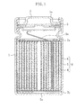
- FIG. 1 is a vertical cross-sectional view illustrating a structure of the nonaqueous electrolyte secondary battery of the first embodiment.
- the nonaqueous electrolyte secondary battery of this embodiment includes a battery case 1 made of, for example, stainless steel and an electrode group 8 placed in the battery case 1.
- An opening 1a is formed in the upper face of the battery case 1.
- a sealing plate 2 is crimped to the opening 1a with a gasket 3 interposed therebetween, thereby sealing the opening 1a.
- the electrode group 8 includes a positive electrode 4, a negative electrode 5, and a porous insulating layer (separator) 6 made of, for example, polyethylene.
- the positive electrode 4 and the negative electrode 5 are wound in a spiral with the separator 6 interposed therebetween.
- An upper insulating plate 7a is placed on top of the electrode group 8.
- a lower insulating plate 7b is placed on the bottom of the electrode group 8.
- One end of a positive electrode lead 4a made of aluminium is attached to the positive electrode 4.
- the other end of the positive electrode lead 4a is attached to the sealing plate 2 also serving as a positive electrode terminal.
- One end of a negative electrode lead 5a made of nickel is attached to the negative electrode 5.
- the other end of the negative electrode lead 5a is connected to the battery case 1 also serving as a negative electrode terminal.
- FIG. 2 is an enlarged cross-sectional view illustrating the structure of the electrode group 8.
- the positive electrode 4 includes a positive electrode current collector 4A and a positive electrode mixture layer 4B.
- the positive electrode current collector 4A is a conductive member in the shape of a plate, specifically is made of aluminium containing iron.
- the positive electrode mixture layer 4B is provided on the surface of the positive electrode current collector 4A, contains a positive electrode active material (e.g., lithium composite oxide), and preferably contains a binder or a conductive agent in addition to the positive electrode active material.
- the tensile extension percentage of the positive electrode 4 is 3% or more. In this manner, since the positive electrode 4 subjected to heat treatment after rolling is used in this embodiment, the tensile extension percentage of the positive electrode 4 is increased to 3% or more.
- the negative electrode 5 includes a negative electrode current collector 5A and a negative electrode mixture layer 5B.
- the negative electrode current collector 5A is a conductive member in the shape of a plate.
- the negative electrode mixture layer 5B is provided on the surface of the negative electrode current collector 5A, contains a negative electrode active material, and preferably contains a binder or a conductive agent in addition to the negative electrode active material.
- the tensile extension percentage of the negative electrode 5 is 3% or more. In general, the tensile extension percentage of a negative electrode using copper foil as a negative electrode current collector is in the range from 3% to 7%.
- the separator 6 is interposed between the positive electrode 4 and the negative electrode 5.
- the tensile extension percentage of the separator 6 is 3% or more.
- the tensile extension percentage of a film separator mainly made of polyethylene is in the range from 8% to 12%.
- the positive electrode according to this disclosure is a positive electrode in which a current collector of aluminium containing iron is employed as a positive electrode current collector and which has an increased tensile extension percentage of 3% or more due to heat treatment performed at a low temperature for a short time after rolling.
- a current collector made of iron-containing aluminium as a positive electrode current collector in this manner can increase the tensile extension percentage of the positive electrode to 3% or more even with heat treatment performed at a lower temperature for a shorter time.
- the positive electrode according to this disclosure i.e., the positive electrode subjected to heat treatment after rolling, has a feature 1) of a tensile extension percentage of 3% or more.
- the positive electrode of this disclosure has two features 2) and 3) as follows:
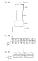
- the "tensile extension percentage of a positive electrode” herein is measured as follows: First, a positive electrode is cut to have a width of 15 mm and an effective length (i.e., the length of an effective portion) of 20 mm, thereby forming a sample positive electrode 19 as illustrated in FIG. 3(a) . Then, one end of the sample positive electrode 19 is placed on a lower chuck 20b supported by a base 21, whereas the other end of the sample positive electrode 19 is placed at an upper chuck 20a connected to a load mechanism (not shown) via a load cell (a load converter, not shown, for converting a load into an electrical signal), thereby holding the sample positive electrode 19.
- a load mechanism not shown
- a load cell a load converter, not shown, for converting a load into an electrical signal
- the upper chuck 20a is moved along the length of the sample positive electrode 19 at a speed of 20 mm/min to extend the sample positive electrode 19.
- the length of the sample positive electrode immediately before the sample positive electrode is broken is measured.
- the tensile extension percentage of the positive electrode is calculated.
- the tensile load on the sample positive electrode 19 is detected from information obtained from the load cell.
- FIGS. 3(b) and (c) are cross-sectional views schematically illustrating the positive electrode in the measurement of the tensile extension percentage. Specifically, FIG. 3(b) shows the positive electrode of this disclosure and FIG. 3(c) shows a conventional positive electrode.
- the positive electrode current collector 9A extends first with fine cracks 10 occurring in the positive electrode mixture layer 9B as illustrated in FIG. 3(b) before the positive electrode current collector 9A is finally broken. In this manner, in the positive electrode 9 of this disclosure, a first crack occurs in the positive electrode mixture layer 9B and, for a short period of time after the first crack, the positive electrode current collector 9A is not broken, and continues to extend with cracks occurring in the positive electrode mixture layer 9B.
- the "dynamic hardness" herein is measured in the following manner: An indenter is pressed into the positive electrode under a given test pressure P (mN) so that the indent depth (the depth of penetration) D ( ⁇ m) at this time can be measured. The obtained indent depth D is introduced to [Equation 1] below, thereby calculating a dynamic hardness DH.
- a Berkovich indenter i.e., a three-sided pyramid indenter with a ridge angle of 115° was used in this case.
- the dynamic hardness herein is hardness calculated based on the indent depth of the indenter into a specimen and differs from, for example, Vickers hardness and Knoop hardness which are widely used for measuring the hardness of metals and for other purposes.
- the dynamic hardness herein differs from hardness calculated based on the surface area of a bump formed by applying a test pressure to a specimen (e.g., a metal) and then removing the test pressure (where the surface area of the bump is calculated from the diagonal length of the bump).
- the "stiffness test” herein is a test in which the circumferential surface of a sample positive electrode having a circumference of 100 mm and rolled up in the shape of a single complete circle is pressed at a given speed. Specifically, a positive electrode is cut to have a width of 10 mm and a length of 100 mm, and the resultant electrode is rolled up to form a single complete circle with both ends thereof placed on top of each other (see an overlapping portion 13a in FIG. 4(a) ), thereby completing a sample positive electrode 13 with a circumference of 100 mm. Then, as shown in FIG.
- the overlapping portion 13a of the sample positive electrode 13 is fixed by a fixing jig (not shown) placed on a lower flat plate 14b, and the sample positive electrode 13 is sandwiched between an upper flat plate 14a and the lower flat plate 14b. Thereafter, the upper flat plate 14a is moved downward at a speed of 10 mm/min, thereby pressing the circumferential surface of the sample positive electrode 13. At this time, stress applied to the sample positive electrode 13 is measured, and the position of the downwardly-moved upper flat plate 14a at the time (see points 16a and 16b in FIG.
- the stiffness test is performed in order to create indexes for easiness of deformation of the positive electrode. As the gap at which an inflection point of stress is observed decreases, the positive electrode is more easily deformed without breakage.
- the positive electrode is not broken first, and thus, short-circuit is not likely to occur in the battery even when the battery is destroyed by crush. Accordingly, the safety of the battery can be enhanced.
- the tensile extension percentages of the negative electrode and the separator also need to be 3% or more as the positive electrode because of the following reasons: First, a negative electrode having a tensile extension percentage less than 3% is broken first upon destruction of the battery by crush, and thus, short-circuit occurs in the battery even though the tensile extension percentages of the positive electrode and the separator are 3% or more, for example.
- a separator having a tensile extension percentage less than 3% is broken first upon destruction of the battery by crush, and thus, short-circuit occurs in the battery even though the tensile extension percentages of the positive electrode and the negative electrode are 3% or more, for example.
- the tensile extension percentage of each of the negative electrode and the separator is 3% or more in this embodiment.
- the use of a current collector of iron-containing aluminium as a positive electrode current collector can increase the tensile extension percentage of the positive electrode to 3% or more even in a case where heat treatment is performed at a lower temperature for a shorter time.
- the reductions in temperature and time of the heat treatment suppress covering of the positive electrode active material with the binder melted during the heat treatment, and thus can avoid a decrease in battery capacity. As a result, a battery exhibiting excellent discharge performance may be provided.
- the dynamic hardness of the positive electrode current collector is 70 or less and the dynamic hardness of the positive electrode mixture layer is 5 or less as described in 2)
- the positive electrode is easily deformed according to the shape of the foreign material. Accordingly, penetration of the foreign material can be suppressed. As a result, the safety of the battery can be further enhanced.
- the advantage of suppression of short-circuit caused by crush in this embodiment. Moreover, the following advantage can be obtained.
- the electrode group employs a positive electrode for which the gap at which an inflection point of stress is observed in a stiffness test is 3 mm or less. Accordingly, although the positive electrode may become thick, breakage of the positive electrode during formation of the electrode group can be suppressed. As a result, a battery exhibiting high productivity can be provided.
- the positive electrode 4 of this embodiment is a positive electrode which employs, as the positive electrode current collector 4A, a current collector of iron-containing aluminium, and which has been subjected to heat treatment at a low temperature for a short time after rolling.
- the positive electrode 4 has the above-mentioned features 1), 2), and 3). Accordingly, the nonaqueous electrolyte secondary battery of this embodiment can exhibit the advantage of suppression of short-circuit caused by crush, the advantage of suppression of short-circuit caused by entering of a foreign material, and the advantage of suppression of breakage of the electrode plate during formation of the group, without a decrease in battery capacity.
- the positive electrode 4, the negative electrode 5, the separator 6, and a nonaqueous electrolyte forming the nonaqueous electrolyte secondary battery of this embodiment are now described in detail.
- a positive electrode current collector 4A and a positive electrode mixture layer 4B constituting the positive electrode 4 are described in order.
- the positive electrode current collector 4A uses a long conductor substrate having a porous or non-porous structure.
- the positive electrode current collector 4A is made of iron-containing aluminium.
- the iron content in the positive electrode current collector is preferably in the range from 1.20 wt% (weight %) to 1.70 wt%, both inclusive.
- the thickness of the positive electrode current collector 4A is not specifically limited, but is preferably in the range from 1 ⁇ m to 500 ⁇ m, both inclusive, and more preferably in the range from 10 ⁇ m to 20 ⁇ m, both inclusive. In this manner, the thickness of the positive electrode current collector 4A is set in the range described above, thus making it possible to reduce the weight of the positive electrode 4 while maintaining the strength of the positive electrode 4.
- the positive electrode mixture layer 4B preferably contains a binder or a conductive agent, in addition to the positive electrode active material.
- the positive electrode active material, the binder, and the conductive agent contained in the positive electrode mixture layer 4B are now described in order.
- the positive electrode active material examples include LiCoO 2 , LiNiO 2 , LiMnO 2 , LiCoNiO 2 , LiCoMO z , LiNiMO z , LiMn 2 O 4 , LiMnMO 4 , LiMePO 4 , Li 2 MePO 4 F (where M is at least one of Na, Mg, Sc, Y, Mn, Fe, Co, Ni, Cu, Zn, Al, Cr, Pb, Sb, and B). In these lithium-containing compounds, an element may be partially substituted with an element of a different type.
- the positive electrode active material may be a positive electrode active material subjected to a surface process using a metal oxide, a lithium oxide, or a conductive agent, for example. Examples of this surface process include hydrophobization.
- the average particle diameter of the positive electrode active material is preferably in the range from 5 ⁇ m to 20 ⁇ m, both inclusive.
- the positive electrode active material is greatly affected by heat treatment performed on the positive electrode, resulting in a rapid decrease in battery capacity (see battery 20 in Table 1 below). It was confirmed that the battery capacity decreases with a decrease in average particle diameter of the positive electrode active material (see batteries 20 to 22 in Table 1 below). This is considered to be because of the following reasons. Since the surface area of the positive electrode active material decreases with a decrease in average particle diameter of the positive electrode active material, the entire surface of the positive electrode active material is more likely to be covered with the binder melted during heat treatment after rolling.
- the average particle diameter of the positive electrode active material is preferably in the range from 5 ⁇ m to 20 ⁇ m, both inclusive.
- binder examples include poly vinylidene fluoride (PVDF), polytetrafluoroethylene, polyethylene, polypropylene, aramid resin, polyamide, polyimide, polyamide-imide, polyacrylonitrile, polyacrylic acid, polyacrylic acid methyl ester, polyacrylic acid ethyl ester, polyacrylic acid hexyl ester, polymethacrylic acid, polymethacrylic acid methyl ester, polymethacrylic acid ethyl ester, polymethacrylic acid hexyl ester, polyvinyl acetate, polyvinyl pyrrolidone, polyether, polyether sulphone, hexafluoropolypropylene, styrene-butadiene rubber, and carboxymethyl cellulose.
- PVDF poly vinylidene fluoride
- aramid resin polyamide, polyimide, polyamide-imide, polyacrylonitrile
- polyacrylic acid polyacrylic acid methyl ester
- binder examples include a copolymer of two or more materials selected from the group consisting of tetrafluoroethylene, hexafluoroethylene, hexafluoropropylene, perfluoroalkylvinylether, vinylidene fluoride, chlorotrifluoroethylene, ethylene, propylene, pentafluoropropylene, fluoromethylvinylether, acrylic acid, and hexadiene, and a mixture of two or more materials selected from these materials.
- a copolymer of two or more materials selected from the group consisting of tetrafluoroethylene, hexafluoroethylene, hexafluoropropylene, perfluoroalkylvinylether, vinylidene fluoride, chlorotrifluoroethylene, ethylene, propylene, pentafluoropropylene, fluoromethylvinylether, acrylic acid, and hexadiene, and a mixture of two or more materials selected
- PVDF and a derivative thereof are particularly chemically stable in a nonaqueous electrolyte secondary battery, and each sufficiently bonds the positive electrode mixture layer 4B and the positive electrode current collector 4A together, and also bonds the positive electrode active material, the binder, and the conductive agent constituting the positive electrode mixture layer 4B. Accordingly, excellent cycle characteristics and high discharge performance can be obtained.
- PVDF or a derivative thereof is preferably used as the binder of this disclosure.
- PVDF and a derivative thereof are available at low cost and, therefore, are preferable.
- PVDF may be dissolved in N methylpyrrolidone, or PVDF powder may be dissolved in positive electrode material mixture slurry, for example, during the formation of the positive electrode.
- rubber-based binders e.g., fluorocarbon rubber and acrylic rubber
- PVDF polyvinylene
- acrylic rubber e.g., polymethyl methacrylate
- rubber-based binders are chemically unstable in a nonaqueous electrolyte secondary battery as compared to PVDF and a derivative thereof, and are unsatisfactory in terms of cycle characteristics and discharge performance.
- the use of a rubber-based binder as a binder makes the tensile extension percentage of the positive electrode higher than that in the case of using PVDF and a derivative thereof as a binder (see batteries 15 to 19 in Table 1 below). Accordingly, short-circuit by crush can be effectively suppressed.
- the dynamic hardness of the positive electrode mixture layer can be lower than that in the case of using PVDF and a derivative thereof as a binder (see batteries 15 to 19 in Table 1 below). Accordingly, short-circuit caused by entering of a foreign material can be effectively suppressed.
- Examples of the conductive agent include graphites such as natural graphite and artificial graphite, carbon blacks such as acetylene black (AB), Ketjen black, channel black, furnace black, lamp black, and thermal black, conductive fibers such as carbon fiber and metal fiber, metal powders such as carbon fluoride and aluminium, conductive whiskers such as zinc oxide and potassium titanate, conductive metal oxides such as titanium oxide, and organic conductive materials such as a phenylene derivative.
- carbon blacks such as acetylene black (AB), Ketjen black, channel black, furnace black, lamp black, and thermal black
- conductive fibers such as carbon fiber and metal fiber
- metal powders such as carbon fluoride and aluminium
- conductive whiskers such as zinc oxide and potassium titanate
- conductive metal oxides such as titanium oxide
- organic conductive materials such as a phenylene derivative.
- a negative electrode current collector 5A and a negative electrode mixture layer 5B constituting the negative electrode 5 are now described in order.
- the negative electrode current collector 5A a long conductive substrate having a porous or non-porous structure is used.
- the negative electrode current collector 5A is made of, for example, stainless steel, nickel, or copper.
- the thickness of the negative electrode current collector 5A is not specifically limited, but is preferably in the range from 1 ⁇ m to 500 ⁇ m, both inclusive, and more preferably in the range from 10 ⁇ m to 20 ⁇ m, both inclusive. In this manner, the thickness of the negative electrode current collector 5A is set in the range described above, thus making it possible to reduce the weight of the negative electrode 5 while maintaining the strength of the negative electrode 5.
- the negative electrode mixture layer 5B preferably contains a binder or a conductive agent, in addition to the negative electrode active material.
- the negative electrode active material contained in the negative electrode mixture layer 5B is now described.
- Examples of the negative electrode active material include metal, metal fiber, a carbon material, oxide, nitride, a silicon compound, a tin compound, and various alloys.
- Examples of the carbon material include various natural graphites, coke, partially-graphitized carbon, carbon fiber, spherical carbon, various artificial graphites, and amorphous carbon.
- the negative electrode active material since simple substances such as silicon (Si) and tin (Sn), silicon compounds, and tin compounds have high capacitance density, it is preferable to use such materials as the negative electrode active material.
- the silicon compound include SiO X (where 0.05 ⁇ x ⁇ 1.95) and a silicon alloy and a silicon solid solution obtained by substituting part of Si with at least one of the elements selected from the group consisting of B, Mg, Ni, Ti, Mo, Co, Ca, Cr, Cu, Fe, Mn, Nb, Ta, V, W, Zn, C, N, and Sn.
- Example of the tin compound include Ni 2 Sn 4 , Mg 2 Sn, SnO X (where 0 ⁇ x ⁇ 2), SnO 2 , and SnSiO 3 .
- One of the examples of the negative electrode active material may be used solely or two or more of them may be used in combination.
- Examples of the separator 6 interposed between the positive electrode 4 and the negative electrode 5 include a microporous thin film, woven fabric, and nonwoven fabric which have high ion permeability, a given mechanical strength, and a given insulation property.
- polyolefin such as polypropylene or polyethylene is preferably used as the separator 6. Since polyolefin has high durability and a shutdown function, the safety of the lithium ion secondary battery can be enhanced.
- the thickness of the separator 6 is generally in the range from 10 ⁇ m to 300 ⁇ m, both inclusive, and preferably in the range from 10 ⁇ m to 40 ⁇ m, both inclusive.
- the thickness of the separator 6 is more preferably in the range from 15 ⁇ m to 30 ⁇ m, both inclusive, and much more preferably in the range from 10 ⁇ m to 25 ⁇ m, both inclusive.
- this microporous thin film may be a single-layer film made of a material of one type, or may be a composite film or a multilayer film made of one or more types of materials.
- the porosity of the separator 6 is preferably in the range from 30% to 70%, both inclusive, and more preferably in the range from 35% to 60%, both inclusive.
- the porosity herein is the volume ratio of pores to the total volume of the separator.
- the nonaqueous electrolyte may be a liquid nonaqueous electrolyte, a gelled nonaqueous electrolyte, or a solid nonaqueous electrolyte.
- the liquid nonaqueous electrolyte i.e., the nonaqueous electrolyte
- contains an electrolyte e.g., lithium salt
- a nonaqueous solvent in which this electrolyte is to be dissolved.
- the gelled nonaqueous electrolyte contains an nonaqueous electrolyte and a polymer material supporting the nonaqueous electrolyte.
- this polymer material include polyvinylidene fluoride, polyacrylonitrile, polyethylene oxide, polyvinyl chloride, polyacrylate, and polyvinylidene fluoride hexafluoropropylene.
- the solid nonaqueous electrolyte contains a solid polymer electrolyte.
- nonaqueous solvent in which an electrolyte is to be dissolved
- a known nonaqueous solvent may be used as a nonaqueous solvent in which an electrolyte is to be dissolved.
- the type of this nonaqueous solvent is not specifically limited, and examples of the nonaqueous solvent include cyclic carbonate, chain carbonate, and cyclic carboxylate.
- Cyclic carbonate may be propylene carbonate (PC) or ethylene carbonate (EC).
- Chain carbonate may be diethyl carbonate (DEC), ethylmethyl carbonate (EMC), or dimethyl carbonate (DMC).
- Cyclic carboxylate may be ⁇ -butyrolactone (GBL) or ⁇ -valerolactone (GVL).
- GBL ⁇ -butyrolactone
- VTL ⁇ -valerolactone
- One of the examples of the nonaqueous solvent may be used solely or two or more of them may be used in combination.
- Examples of the electrolyte to be dissolved in the nonaqueous solvent include LiClO 4 , LiBF 4 , LiPF 6 , LiAlCl 4 , LiSbF 6 , LiSCN, LiCF 3 SO 3 , LiCF 3 CO 2 , LiAsF 6 , LiB 10 Cl 10 , lower aliphatic lithium carboxylate, LiCl, LiBr, LiI, chloroborane lithium, borates, and imidates.
- borates examples include bis(1,2-benzene diorate(2-)-O,O')lithium borate, bis(2,3-naphthalene diorate(2-)-O,O')lithium borate, bis(2,2'-biphenyl diorate(2-)-O,O')lithium borate, and bis(5-fluoro-2-orate-l-benzenesulfonic acid-O,O')lithium borate.
- Examples of the imidates include lithium bistr-ifluoromethanesulfonimide ((CF 3 SO 2 ) 2 NLi), lithium trifluoromethanesulfonate nonafluorobutanesulfonimide (LiN(CF 3 SO 2 )(C 4 F 9 SO 2 )), and lithium bispentafluoroethanesulfonimide ((C 2 F 5 SO 2 ) 2 NLi).
- One of these electrolytes may be used solely or two or more of them may be used in combination.
- the amount of the electrolyte dissolved in the nonaqueous solvent is preferably in the range from 0.5 mol/m 3 to 2 mol/m 3 , both inclusive.
- the nonaqueous electrolyte may contain an additive which is decomposed on the negative electrode and forms thereon a coating having high lithium ion conductivity to enhance the charge-discharge efficiency, for example, in addition to the electrolyte and the nonaqueous solvent.
- Examples of the additive having such a function include vinylene carbonate (VC), 4-methylvinylene carbonate, 4,5-dimethylvinylene carbonate, 4-ethylvinylene carbonate, 4,5-diethylvinylene carbonate, 4-propylvinylene carbonate, 4,5-dipropylvinylene carbonate, 4-phenylvinylene carbonate, 4,5-diphenylvinylene carbonate, vinyl ethylene carbonate (VEC), and divinyl ethylene carbonate.
- One of the additives may be used solely or two or more of them may be used in combination.
- at least one selected from the group consisting of vinylene carbonate, vinyl ethylene carbonate, and divinyl ethylene carbonate is preferable.
- hydrogen atoms may be partially substituted with fluorine atoms.
- the nonaqueous electrolyte may further contain, for example, a known benzene derivative which is decomposed during overcharge and forms a coating on the electrode to inactivate the battery, in addition to the electrolyte and the nonaqueous solvent.
- the benzene derivative having such a function preferably includes a phenyl group and a cyclic compound group adjacent to the phenyl group. Examples of the benzene derivative include cyclohexylbenzene, biphenyl, and diphenyl ether.
- Examples of the cyclic compound group included in the benzene derivative include a phenyl group, a cyclic ether group, a cyclic ester group, a cycloalkyl group, and a phenoxy group.
- One of the benzene derivatives may be used solely or two or more of them may be used in combination. However, the content of the benzene derivative is preferably 10 vol% or less of the total volume of the nonaqueous solvent.
- the structure of the nonaqueous electrolyte secondary battery of this embodiment is not limited to the structure illustrated in FIG. 1 .
- the nonaqueous electrolyte secondary battery of this embodiment is not limited to a cylindrical shape as shown in FIG. 1 , and may be prism-shaped or a high-power lithium ion secondary battery.
- the structure of the electrode group 8 is not limited to the spiral provided by wounding the positive electrode 4 and the negative electrode 5 with the separator 6 interposed therebetween (see FIG. 1 ).
- the positive and negative electrodes may be stacked with the separator interposed therebetween.
- a positive electrode 4 is formed in the following manner: For example, a positive electrode active material, a binder (which is preferably made of PVDF or a derivative thereof or a rubber-based binder as described above), and a conductive agent are first mixed in a liquid component, thereby preparing positive electrode material mixture slurry. Then, this positive electrode material mixture slurry is applied onto the surface of a positive electrode current collector 4A made of iron-containing aluminium, and is dried. Thereafter, the resultant positive electrode current collector 4A is rolled, thereby forming a positive electrode having a given thickness. Subsequently, the positive electrode is subjected to heat treatment at a given temperature for a given period of time. The given temperature herein is higher than the softening temperature of the positive electrode current collector 4A and lower than the decomposition temperature of the binder.
- the heat treatment performed on the positive electrode is carried out by using hot air subjected to low humidity treatment at a given temperature or by bringing a heated roll at a given temperature into contact with the positive electrode, for example.
- the amount of the binder contained in the positive electrode material mixture slurry is preferably in the range from 3.0 vol% to 6.0 vol%, both inclusive, with respect to 100.0 vol% of the positive electrode active material.
- the amount of the binder contained in the positive electrode mixture layer is preferably in the range from 3.0 vol% to 6.0 vol%, both inclusive, with respect to 100.0 vol% of the positive electrode active material.
- the battery capacity When the amount of the binder contained in the positive electrode material mixture slurry exceeds 6.0 vol%, the battery capacity rapidly decreases (see batteries 14 and 19 in Table 1 below). It was confirmed that when the amount of the binder contained in the positive electrode material mixture slurry is 3.0 vol% or more, the battery capacity decreases with an increase in amount of the binder (see batteries 12 to 14 and batteries 16 to 19 in Table 1 below). This is considered to be because of the following reasons. It is thought that with an increase in amount of the binder contained in the positive electrode material mixture slurry, the amount of the binder melted during heat treatment after rolling increases, and thus, the positive electrode active material is more likely to be covered with the melted binder.
- the amount of the binder contained in the positive electrode material mixture slurry is preferably in the range from 3 vol% to 6 vol%, both inclusive.
- a first heat treatment condition is preferably that the given temperature is in the range from 250°C to 350°C, both inclusive, and the heat treatment time is in the range from 10 seconds to 120 seconds, both inclusive, for example.
- a second heat treatment condition is preferably that the given temperature is in the range from 220°C to 250°C, both inclusive, and the heat treatment time is in the range from 2 minutes to 60 minutes, both inclusive, for example.
- a third heat treatment condition is preferably that the given temperature is in the range from 160°C to 220°C, both inclusive, and the heat treatment time is in the range from 60 minutes to 600 minutes, both inclusive, for example.
- first heat treatment condition 10 seconds
- second heat treatment condition 2 minutes
- third heat treatment condition 60 minutes
- the heat treatment time is longer than the upper limit of the above-mentioned range (i.e., first heat treatment condition: 120 seconds, second heat treatment condition: 60 minutes, and third heat treatment condition: 600 minutes) in the first through third heat treatment conditions
- the heat treatment time is longer than the upper limit of the above-mentioned range (i.e., first heat treatment condition: 120 seconds, second heat treatment condition: 60 minutes
- third heat treatment condition 600 minutes
- the heat treatment time can be shorter than that in the case of performing heat treatment on the positive electrode with hot air. Accordingly, productivity can be enhanced.
- the positive electrode may employ a positive electrode current collector having a relatively large thickness. Specifically, if a positive electrode current collector with a thickness of 15 ⁇ m (which is used for fabricating a commonly-used 18650-size lithium ion secondary battery) is used in forming a positive electrode, it is easy to increase the tensile extension percentage of the positive electrode to 3% or more, but it is relatively difficult to increase this percentage to 6% or more. On the other hand, if a positive electrode current collector with a thickness of 30 ⁇ m is used in forming a positive electrode, the tensile extension percentage of the positive electrode can be increased to as high as 13%.
- a negative electrode 5 is formed in the following manner: For example, a negative electrode active material and a binder are first mixed in a liquid component, thereby preparing negative electrode material mixture slurry. Then, this negative electrode material mixture slurry is applied onto the surface of a negative electrode current collector 5A, and is dried. Thereafter, the resultant negative electrode current collector 5A is rolled up, thereby forming a negative electrode having a given thickness. After rolling, the negative electrode may be subjected to heat treatment at a given temperature for a given time.
- a battery is fabricated in the following manner: For example, as illustrated in FIG. 1 , an aluminium positive electrode lead 4a is attached to a positive electrode current collector (see 4A in FIG. 2 ), and a nickel negative electrode lead 5a is attached to a negative electrode current collector (see 5A in FIG. 2 ). Then, a positive electrode 4 and a negative electrode 5 are wound with a separator 6 interposed therebetween, thereby forming an electrode group 8. Thereafter, an upper insulating plate 7a is placed on the upper end of the electrode group 8, and a lower insulating plate 7b is placed on the lower end of the electrode group 8.
- the negative electrode lead 5a is welded to a battery case 1, and the positive electrode lead 4a is welded to a sealing plate 2 including a safety valve operated with inner pressure, thereby housing the electrode group 8 in the battery case 1.
- a nonaqueous electrolyte is poured in the battery case 1 under a reduced pressure.
- an opening end of the battery case 1 is crimped to the sealing plate 2 with a gasket 3 interposed therebetween, thereby completing a battery.
- heat treatment on the positive electrode is performed after rolling. This can increase the tensile extension percentage of the positive electrode to 3% or more.
- it is possible to reduce the hardness of the positive electrode specifically, to reduce the dynamic hardness of the positive electrode current collector to 70 or less and the dynamic hardness of the positive electrode mixture layer to 5 or less). It is also possible to obtain a sample positive electrode which is not broken until the gap (see 15 in FIG. 4(a) ) reaches 3 mm, inclusive, in a stiffness test.
- a current collector made of iron-containing aluminium is employed as the positive electrode current collector.
- heat treatment for increasing the tensile extension percentage of the positive electrode needs to be performed after rolling. If heat treatment is performed before rolling, the tensile extension percentage of the positive electrode can be increased during the heat treatment, but this percentage decreases during subsequent rolling. Consequently, the resultant tensile extension percentage of the positive electrode cannot be increased.
- heat treatment is performed on the positive electrode at a given temperature for a given time after rolling. This can increase the tensile extension percentage of the positive electrode to 3% or more. Accordingly, even when the battery is destroyed by crush, the positive electrode is not broken first, and thus, short-circuit is not likely to occur in the battery. As a result, the safety of the battery can be enhanced.
- the current collector made of iron-containing aluminium is employed as the positive electrode current collector. Accordingly, it is possible to increase the tensile extension percentage of the positive electrode to 3% or more even with heat treatment performed at a lower temperature for a shorter time. As a result, no decrease in battery capacity can be avoided.
- the dynamic hardness of the positive electrode current collector is 70 or less, and the dynamic hardness of the positive electrode mixture layer is 5 or less. Accordingly, even with entering of a foreign material into the electrode group, the positive electrode is easily deformed according to the shape of the foreign material during charge or discharge, thus suppressing penetration of the foreign material into the separator. As a result, the safety of the battery may be further enhanced.
- the electrode group is formed by using the positive electrode for which the gap where an inflection point of stress is observed in a stiffness test is 3 mm or less. Accordingly, breakage of the positive electrode in forming the electrode group can be suppressed even when the positive electrode becomes thicker.
- heat treatment is performed on the positive electrode after rolling and before formation of the electrode group in this embodiment. This can suppress short-circuit caused by crush, short-circuit caused by entering of a foreign material, and breakage of the electrode plate in formation of the electrode group without a decrease in battery capacity.
- the separator has a tensile extension percentage of 3% or more, whereas the negative electrode does not have a tensile extension percentage of 3% or more in some cases, although having a tensile extension percentage of 3% or more in most cases.
- This embodiment employs a negative electrode having a tensile extension percentage of 3% or more.
- heat treatment may be performed on the negative electrode at a given temperature for a given time after rolling and before formation of the electrode group in forming the negative electrode. Then, the negative electrode has a tensile extension percentage of 3% or more without fail.
- heat treatment performed on the negative electrode is not specifically described in this embodiment, the inventors intensively studied to fined the followings: First, in the case of using copper foil as the negative electrode current collector, heat treatment performed on the negative electrode at, for example, about 200 °C may increase the tensile extension percentage of the negative electrode. Second, in the case of using rolled-up copper foil as the negative electrode current collector, the tensile extension percentage of the negative electrode may be effectively increased, as compared to the case of using electrolytic copper foil.
- Example 1 (batteries 1 to 4), Example 2 (batteries 5 to 7), Example 3 (batteries 8 to 10), Example 4 (batteries 11 to 14), Example 5 (batteries 15 to 19), Example 6 (batteries 20 to 22), Example 7 (battery 23), and Comparative Example (batteries 24 and 25) are specifically described.
- Each of the batteries 1 to 25 employs a separator having a tensile extension percentage of 8% (i.e., 3% or more) and a negative electrode having a tensile extension percentage of 5% (i.e., 3% or more).
- Example 1 batteries 1 to 4 were fabricated.
- Each of the batteries 1 to 4 is characterized in that a current collector made of iron-containing aluminium was used as a positive electrode current collector, that PVDF was used as a binder, and that a positive electrode subjected to heat treatment with hot air at 280 °C for a given time (specifically, battery 1: 20 seconds, battery 2: 120 seconds, battery 3: 180 seconds, and battery 4: 10 seconds) was employed.
- a method for fabricating a battery 1 is now specifically described.
- LiNi 0.82 Co 0.15 Al 0.03 O 2 having an average particle diameter of 10 ⁇ m was prepared.
- the resultant positive electrode current collector whose both surfaces were coated with the dried positive electrode material mixture slurry was rolled, thereby obtaining a positive electrode plate in the shape of a plate having a thickness of 0.157 mm.
- This positive electrode plate was then subjected to heat treatment at 280°C for 20 seconds by using hot air subjected to low humidity treatment at -30°C. Subsequently, the positive electrode plate was cut to have a width of 57 mm and a length of 564 mm, thereby obtaining a positive electrode having a thickness of 0.157 mm, a width of 57 mm, and a length of 564 mm.
- This negative electrode plate was subjected to heat treatment with hot air in a nitrogen atmosphere at 190°C for 8 hours.
- the negative electrode plate was then cut to have a width of 58.5 mm and a length of 750 mm, thereby obtaining a negative electrode having a thickness of 0.156 mm, a width of 58.5mm, and a length of 750 mm.
- a positive electrode lead made of aluminium was attached to the positive electrode current collector, and a negative electrode lead made of nickel was attached to the negative electrode current collector. Then, the positive electrode and the negative electrode were wound with a polyethylene separator interposed therebetween, thereby forming an electrode group. Thereafter, an upper insulating plate was placed at the upper end of the electrode group, and a lower insulating plate was placed at the bottom end of the electrode group. Subsequently, the negative electrode lead was welded to a battery case, and the positive electrode lead was welded to a sealing plate including a safety valve operated with inner pressure, thereby housing the electrode group in the battery case. Then, the nonaqueous electrolyte was poured in the battery case under reduced pressure. Lastly, an opening end of the battery case was crimped to the sealing plate with a gasket interposed therebetween.
- the battery including the positive electrode subjected to heat treatment at 280°C for 20 seconds in the foregoing manner is hereinafter referred to as the battery 1.
- a battery 2 was fabricated in the same manner as for the battery 1 except for that the positive electrode plate of the battery 2 was subjected to heat treatment at 280°C for 120 seconds in (Formation of Positive Electrode).
- a battery 3 was fabricated in the same manner as for the battery 1 except for that the positive electrode plate of the battery 3 was subjected to heat treatment at 280°C for 180 seconds in (Formation of Positive Electrode).
- a battery 4 was fabricated in the same manner as for the battery 1 except for that the positive electrode plate of the battery 4 was subjected to heat treatment at 280°C for 10 seconds in (Formation of Positive Electrode).
- Example 2 batteries 5 to 7 were fabricated.
- Each of the batteries 5 to 7 is characterized in that a current collector made of iron-containing aluminium was used as a positive electrode current collector, that PVDF was used as a binder, and that a positive electrode subjected to heat treatment with hot air at 230 °C for a given time (specifically, battery 5: 15 minutes, battery 6: 1 minute, and battery 7: 240 minutes).
- a battery 5 was fabricated in the same manner as for the battery 1 except for that the positive electrode plate of the battery 5 was subjected to heat treatment at 230°C for 15 minutes in (Fabrication of Positive Electrode).
- a battery 6 was fabricated in the same manner as for the battery 1 except for that the positive electrode plate of the battery 6 was subjected to heat treatment at 230°C for 1 minute in (Fabrication of Positive Electrode).
- a battery 7 was fabricated in the same manner as for the battery 1 except for that the positive electrode plate of the battery 7 was subjected to heat treatment at 230°C for 240 minutes in (Fabrication of Positive Electrode).
- Example 3 batteries 8 to 10 were fabricated.
- Each of the batteries 8 to 10 is characterized in that a current collector made of iron-containing aluminium was used as a positive electrode current collector, that PVDF was used as a binder, and that a positive electrode subjected to heat treatment with hot air at 180 °C for a given time (specifically, battery 8: 60 minutes, battery 9: 180 minutes, and battery 10: 1200 minutes).
- a battery 8 was fabricated in the same manner as for the battery 1 except for that the positive electrode plate of the battery 8 was subjected to heat treatment at 180°C for 60 minutes in (Fabrication of Positive Electrode).
- a battery 9 was fabricated in the same manner as for the battery 1 except for that the positive electrode plate of the battery 9 was subjected to heat treatment at 180°C for 180 minutes in (Fabrication of Positive Electrode).
- a battery 10 was fabricated in the same manner as for the battery 1 except for that the positive electrode plate of the battery 10 was subjected to heat treatment at 180°C for 1200 minutes in (Fabrication of Positive Electrode).
- Example 4 batteries 11 to 14 were fabricated.
- Each of the batteries 11 to 14 is characterized in that a current collector made of iron-containing aluminium was used as a positive electrode current collector, that a positive electrode subjected to heat treatment with hot air at 280 °C for 20 seconds was used, and that the amount of a binder (PVDF) contained in the positive electrode differs among the batteries.
- a current collector made of iron-containing aluminium was used as a positive electrode current collector
- a positive electrode subjected to heat treatment with hot air at 280 °C for 20 seconds was used
- the amount of a binder (PVDF) contained in the positive electrode differs among the batteries.
- the batteries of this example differ from the battery 1 in that positive electrode material mixture slurry in (Fabrication of Positive Electrode) contains 2.5 vol%, 3.0 vol%, 6.0 vol%, or 6.5 vol% of PVDF in the batteries of this example, but contains 4.7 vol% of PVDF in the battery 1, with respect to 100.0 vol% of the positive electrode active material.
- a battery 11 was fabricated in the same manner as for the battery 1 except for that positive electrode material mixture slurry containing 2.5 vol% of PVDF with respect to 100.0 vol% of the positive electrode active material was used in (Fabrication of Positive Electrode).
- a battery 12 was fabricated in the same manner as for the battery 1 except for that positive electrode material mixture slurry containing 3.0 vol% of PVDF with respect to 100.0 vol% of the positive electrode active material was used in (Fabrication of Positive Electrode).
- a battery 13 was fabricated in the same manner as for the battery 1 except for that positive electrode material mixture slurry containing 6.0 vol% of PVDF with respect to 100.0 vol% of the positive electrode active material was used in (Fabrication of Positive Electrode).
- a battery 14 was fabricated in the same manner as for the battery 1 except for that positive electrode material mixture slurry containing 6.5 vol% of PVDF with respect to 100.0 vol% of the positive electrode active material was used in (Fabrication of Positive Electrode).
- Example 5 batteries 15 to 19 were fabricated.
- Each of the batteries 15 to 19 is characterized in that a current collector made of iron-containing aluminium was used as a positive electrode current collector, that a positive electrode subjected to heat treatment with hot air at 280 °C for 20 seconds, that a PVDF was replaced by a rubber binder (BM500B produced by Zeon Corporation) as a binder, and that the amount of the binder (rubber binder) contained in the positive electrode differs among the batteries.
- BM500B produced by Zeon Corporation
- a battery 15 was fabricated in the same manner as for the battery 1 except for that a rubber binder was used instead of PVDF and that positive electrode material mixture slurry containing 2.5 vol% of the rubber binder with respect to 100.0 vol% of the positive electrode active material was used in (Fabrication of Positive Electrode).
- a battery 16 was fabricated in the same manner as for the battery 1 except for that a rubber binder was used instead of PVDF and that positive electrode material mixture slurry containing 3.0 vol% of the rubber binder with respect to 100.0 vol% of the positive electrode active material was used in (Fabrication of Positive Electrode).
- a battery 17 was fabricated in the same manner as for the battery 1 except for that a rubber binder was used instead of PVDF and that positive electrode material mixture slurry containing 4.5 vol% of the rubber binder with respect to 100.0 vol% of the positive electrode active material was used in (Fabrication of Positive Electrode).
- a battery 18 was fabricated in the same manner as for the battery 1 except for that a rubber binder was used instead of PVDF and that positive electrode material mixture slurry containing 6.0 vol% of the rubber binder with respect to 100.0 vol% of the positive electrode active material was used in (Fabrication of Positive Electrode).
- a battery 19 was fabricated in the same manner as for the battery 1 except for that a rubber binder was used instead of PVDF and that positive electrode material mixture slurry containing 6.5 vol% of the rubber binder with respect to 100.0 vol% of the positive electrode active material was used in (Fabrication of Positive Electrode).
- Example 6 batteries 20 to 22 were fabricated.
- Each of batteries 20 to 22 is characterized in that a current collector made of iron-containing aluminium was used as a positive electrode current collector, that PVDF was used as a binder, that a positive electrode subjected to heat treatment with hot air at 280 °C for 20 seconds was used, and that the average particle diameter of a positive electrode active material differs among the batteries (specifically battery 20: 1 ⁇ m, battery 21: 5 ⁇ m, and battery 22: 20 ⁇ m).
- the batteries of this example differ from the battery 1 in that the average particle diameter of the positive electrode active material in (Fabrication of Positive Electrode) is 1 ⁇ m, 5 ⁇ m, or 20 ⁇ m in the batteries of this example, but is 10 ⁇ m in the battery 1.
- a battery 20 was fabricated in the same manner as for the battery 1 except for that a positive electrode active material having an average particle diameter of 1 ⁇ m was used in (Fabrication of Positive Electrode).
- a battery 21 was fabricated in the same manner as for the battery 1 except for that a positive electrode active material having an average particle diameter of 5 ⁇ m was used in (Fabrication of Positive Electrode).
- a battery 22 was fabricated in the same manner as for the battery 1 except for that a positive electrode active material having an average particle diameter of 20 ⁇ m was used in (Fabrication of Positive Electrode).
- Example 7 a battery 23 was fabricated.
- the battery 23 is characterized in that a current collector made of iron-containing aluminium was used as a positive electrode current collector, that PVDF was used as a binder, and that a positive electrode subjected to heat treatment performed by using a heated roll, instead of hot air, after rolling was used.
- a battery 23 was fabricated in the same manner as for the battery 1 except for that the heat treatment performed with hot air at 280 °C for 20 seconds was replaced by heat treatment with a heated roll in (Fabrication of Positive Electrode).
- the heat treatment with a heated roll is performed by bringing a heated roll at 280°C into contact with the surface of the positive electrode plate for 2 seconds. In this manner, only by setting, at a short time (e.g., 2 seconds), the contact time (i.e., heat treatment time) during which the surface of the positive electrode plate is in contact with the heated roll, the surface temperature of the positive electrode plate can reach 250°C.
- a battery 24 was fabricated in the same manner as for the battery 1 except for that no heat treatment was performed on a positive electrode plate after rolling in (Fabrication of Positive Electrode).
- a battery 25 was fabricated in the same manner as for the battery 1 except for that no heat treatment was performed on a positive electrode plate after rolling using a rubber binder (BM500B produced by Zeon Corporation), instead of PVDF, as a binder in (Fabrication of Positive Electrode).
- BM500B rubber binder produced by Zeon Corporation
- each of the batteries 1 to 25 was charged to a voltage of 4.25 V at a constant current of 1.45 A, and was charged to a current of 50 mA at a constant voltage. Then, each of the resultant batteries 1 to 25 was disassembled, and a positive electrode was taken out. This positive electrode was then cut to have a width of 15 mm and an effective length of 20 mm, thereby forming a sample positive electrode. Thereafter, one end of the sample positive electrode was fixed, and the other end of the sample positive electrode was extended along the longitudinal direction thereof at a speed of 20 mm/min. At this time, the length of the sample positive electrode immediately before breakage was measured.
- the tensile extension percentage of the positive electrode was calculated.
- the tensile extension percentages of the positive electrodes of the batteries 1 to 25 are shown in Table 1 below.
- the tensile extension percentages of the negative electrode and the separator were also measured in the same manner as for measurement of the tensile extension percentage of the positive electrode.
- the tensile extension percentage of the negative electrode (or the separator) was calculated. Although the tensile extension percentages of the negative electrode and the separator of each of the batteries 1 to 25 are not shown in Table 1, the tensile extension percentage of the negative electrode is 5% and the tensile extension percentage of the separator is 8% in each of the batteries 1 to 25.
- each of the batteries 1 to 25 was charged to a voltage of 4.25 V at a constant current of 1.45 A, and was charged to a current of 50 mA at a constant voltage. Then, each of the resultant batteries 1 to 25 was disassembled, and a positive electrode was taken out. For this positive electrode, the dynamic hardness of the positive electrode current collector and the dynamic hardness of the positive electrode mixture layer were measured with Shimadzu Dynamic Ultra Micro Hardness Tester DUH-W201. The dynamic hardnesses of the current collector and the mixture layer of the positive electrode in each of the batteries 1 to 25 are shown in Table 1 below.
- each of the batteries 1 to 25 was charged to a voltage of 4.25 V at a constant current of 1.45 A, and was charged to a current of 50 mA at a constant voltage. Then, each of the resultant batteries 1 to 25 was disassembled, and a positive electrode was taken out. This positive electrode was cut to have a width of 10 mm and a length of 100 mm. The resultant positive electrode was rolled up to form a single complete circle with both ends thereof placed on top of each other, thereby forming a sample positive electrode (see 13 in FIG. 4(a) ). The overlapping portion (i.e., 13a in FIG.
- the "inflection point of stress” herein means that the sample positive electrode which was being deformed by crush according to the movement of the upper flat plate could not be deformed any more and was broken. Results of the stiffness tests on the positive electrodes of the batteries 1 to 25 are shown in Table 1 below.
- the battery capacity was measured for each of the batteries 1 to 25 in the following manner:
- Each of the batteries 1 to 25 was charged to a voltage of 4.2 V at a constant current of 1.4 A in an atmosphere of 25°C, and was charged to a current of 50 mA at a constant voltage of 4.2 V. Then, the battery was discharged to a voltage of 2.5 V at a constant current of 0.56 A, and the capacity of the battery at this time was measured.
- each of the batteries 1 to 25 was charged to a voltage of 4.25 V at a constant current of 1.45 A, and was charged to a current of 50 mA at a constant voltage. Then, a round bar with a diameter of 6 ⁇ was brought into contact with each of the batteries 1 to 25 at a battery temperature of 30°C, and was moved in the depth direction of the battery at a speed of 0.1 mm/sec. In this manner, each of the batteries 1 to 25 was crushed. The amount of deformation of the battery along the depth thereof at the time of occurrence of short-circuit in the battery was measured with a displacement sensor. Results of the crush test on each of the batteries 1 to 25 are shown in Table 1 below.
- each of the batteries 1 to 25 was charged to a voltage of 4.25 V at a constant current of 1.45 A, and was charged to a current of 50 mA at a constant voltage. Then, the electrode group was taken out from the battery case. Subsequently, a nickel plate 17 having a thickness of 0.1 mm (see a in FIG. 5(a) ), a length of 2 mm (see b in FIG. 5(a) ), and a width of 0.2 mm (see c in FIG.
- a nickel plate 18 in the shape of L in cross section having a thickness of 0.1 mm (see A in FIG. 5(b) ) and a height of 0.2 mm (see C in FIG. 5(b) ).
- This nickel plate 18 was interposed between the positive electrode and the separator at respective portions thereof closest to the circumference of the electrode group with the height direction of the nickel plate 18 oriented perpendicularly to the surfaces of the positive electrode and the separator (i.e., the thickness direction of the nickel plate 18 being in parallel with the surfaces of the positive electrode and the separator).
- the positive electrode and the negative electrode were wound with the separator interposed therebetween with a tension of 1.2 kg applied, thereby preparing 50 cells of each of the batteries 1 to 25.
- the number of broken positive electrodes among the 50 cells i.e., the number of broken positive electrodes per 50 cells
- Results of the electrode plate breakage evaluation on each of the batteries 1 to 25 are shown in Table 1 below.
- Table 1 shows characteristics of the positive electrode of each of the batteries 1 to 25 (specifically, “tensile extension percentage of positive electrode”, “dynamic hardness of current collector”, “dynamic hardness of mixture layer”, and “gap in stiffness test”).
- Table 1 shows the "battery capacities" of the batteries 1 to 25, the crush test results of the batteries 1 to 25 (see “short-circuit depth” in Table 1), the foreign material entering test results (see “short-circuit number” in Table 1), and the electrode plate breakage evaluation results (see “breakage number” in Table 1).
- the batteries 1 to 23 of Examples 1 to 7 and the batteries 24 and 25 of Comparative Example are now compared with each other based on Table 1.
- Each of the batteries 1 to 23 employs a positive electrode subjected to heat treatment after rolling, whereas each of the batteries 24 and 25 employs a positive electrode subjected to no heat treatment after rolling.
- Table 1 shows that the tensile extension percentage of the positive electrode subjected to heat treatment after rolling is increased to 3% or more. Table 1 also shows that the batteries 1 to 23 employing positive electrodes whose tensile extension percentages are 3% or more can suppress short-circuit caused by crush.
- Table 1 shows that in the positive electrode subjected to heat treatment after rolling, the dynamic hardness of the current collector is reduced to 70 or less and the dynamic hardness of the mixture layer is reduced to 5 or less.
- Table 1 also shows that the batteries 1 to 23 employing the positive electrodes in each of which the dynamic hardness of the current collector is 70 or less and the dynamic hardness of the mixture layer is 5 or less can suppress short-circuit caused by entering of a foreign material.
- Table 1 shows that in the positive electrode subjected to heat treatment after rolling, the gap in the stiffness test is reduced to 3 mm or less. Table 1 also shows that the batteries 1 to 23 employing the positive electrodes for each of which the gap is 3 mm or less can suppress electrode plate breakage during formation of the electrode group.
- the batteries 1 to 4 of Example 1 employ positive electrodes subjected to heat treatment with hot air at an identical temperature (specifically, 280°C) for different heat treatment times (i.e., battery 1: 20 seconds, battery 2: 120 seconds, battery 3: 180 seconds, and battery 4: 10 seconds).
- Table 1 shows that, with an increase in heat treatment time, the tensile extension percentage of the positive electrode increases, the dynamic hardness of the current collector decreases, the dynamic hardness of the mixture layer decreases, and the gap in the stiffness test decreases in the batteries 1 to 4. This demonstrates that characteristics of the positive electrode are affected by the time of heat treatment after rolling.
- Table 1 also shows that, with an increase in heat treatment time, the short-circuit depth tends to increase and the number of batteries showing occurrence of short-circuit in the foreign material entering test tends to decrease in the batteries 1 to 4. This demonstrates that the batteries 1 to 4 effectively suppress short-circuit caused by crush and short-circuit caused by entering of a foreign material, with an increase in heat treatment time.
- the heat treatment time of the battery 3 is 180 seconds, i.e., longer than those of the batteries 1, 2, and 4 (specifically, battery 1: 20 seconds, battery 2: 120 seconds, battery 4: 10 seconds).
- the battery capacity of the battery 3 is smaller than those of the batteries 1, 2, and 4.
- the binder is melted during the heat treatment to cover the positive electrode active material, resulting in a decrease in battery capacity.
- heat treatment at 280°C is preferably performed for a heat treatment time less than 180 seconds (preferably, 120 seconds or less).
- the heat treatment time of the battery 4 is 10 seconds, and is shorter than those of the batteries 1 and 2 (specifically, battery 1: 20 seconds, and battery 2: 120 seconds).
- the short-circuit depth of the battery 4 is smaller than those of the batteries 1 and 2, and the short-circuit number of the battery 4 is greater than those of the batteries 1 and 2. Since the heat treatment time after rolling for the battery 4 is shorter than those for the batteries 1 and 2 as described above, it is difficult to effectively suppress short-circuit caused by crush and short-circuit caused by entering of a foreign material in the case of the battery 4.
- the batteries 5 to 7 of Example 2 employ positive electrodes subjected to heat treatment with hot air at an identical temperature (specifically, 230°C) for different heat treatment times (i.e., battery 5: 15 minutes, battery 6: 1 minute, and battery 7: 240 minutes).
- Table 1 shows that, with an increase in heat treatment time, the tensile extension percentage of the positive electrode increases and the gap in the stiffness test decreases in the batteries 5 to 7. This demonstrates that characteristics of the positive electrode are affected by heat treatment time after rolling.
- Table 1 also shows that, with an increase in heat treatment time, the short-circuit depth tends to increase and the number of batteries showing occurrence of short-circuit in the foreign material entering test tends to decrease in the batteries 5 to 7. This demonstrates that the batteries 5 to 7 effectively suppresses short-circuit caused by crush and short-circuit caused by entering of a foreign material, with an increase in heat treatment time.
- the heat treatment time of the battery 7 is 240 minutes, i.e., longer than those of the batteries 5 and 6 (specifically, battery 5: 15 minutes and battery 6: 1 minute).
- the battery capacity of the battery 7 is lower than those of the batteries 5 and 6.
- the binder is melted during the heat treatment to cover the positive electrode active material, resulting in a decrease in battery capacity.
- heat treatment at 230°C is preferably performed for a heat treatment time less than 240 minutes (preferably, 60 minutes or less).
- the heat treatment time of the battery 6 is 1 minute, i.e., shorter than that of the battery 5 (specifically, battery 5: 15 minutes).
- the short-circuit depth of the battery 6 is smaller than that of the battery 5 and, moreover, the short-circuit number of the battery 6 is greater than that of the battery 5. Since the heat treatment time after rolling for the battery 6 is short as described above, it is difficult for the battery 6 to sufficiently suppress short-circuit caused by crush and short-circuit caused by entering of a foreign material, as compared to the battery 5.
- heat treatment at 230°C is preferably performed for a heat treatment time exceeding 1 minute (preferably, 2 minutes or more).
- the batteries 8 to 10 of Example 3 employ positive electrodes subjected to heat treatment with hot air at an identical temperature (specifically, 180°C) for different heat treatment times (i.e., battery 8: 60 minutes, battery 9: 180 minutes, and battery 10: 1200 minutes).
- Table 1 shows that, with an increase in heat treatment time, the tensile extension percentage of the positive electrode increases and the gap in the stiffness test decreases in the batteries 8 to 10. This demonstrates that characteristics of the positive electrode are affected by the heat treatment time after rolling.
- Table 1 also shows that, with an increase in heat treatment time, the short-circuit depth tends to increase and the number of batteries showing occurrence of short-circuit in the foreign material entering test tends to decrease in the batteries 8 to 10. This demonstrates that the batteries 8 to 10 effectively suppress short-circuit caused by crush and short-circuit caused by entering of a foreign material, with an increase in heat treatment time.
- the heat treatment time of the battery 10 is 1200 minutes, and is longer than those of the batteries 8 and 9 (specifically, battery 8: 60 minutes and battery 9: 180 minutes).
- the battery capacity of the battery 10 is lower than those of the batteries 8 and 9.
- the binder is melted during the heat treatment to cover the positive electrode active material, resulting in a decrease in battery capacity.
- heat treatment at 180°C is preferably performed for a heat treatment time less than 1200 minutes (preferably, 600 minutes or less).
- the batteries 11 to 14 of Example 4 employ positive electrodes subjected to heat treatment with hot air at 280°C for 20 seconds, and exhibit different amounts of binders (PVDF) contained in the positive electrodes.
- the batteries 11 to 14 employ positive electrode material mixture slurry containing binders in different amounts (specifically, battery 11: 2.5 vol%, battery 12: 3.0 vol%, battery 13: 6.0 vol%, and battery 14: 6.5 vol%) in forming the positive electrodes.
- Table 1 shows that no significant differences in characteristics of the positive electrode are observed among the batteries 11 to 14. This demonstrates that characteristics of the positive electrode are not greatly affected by the amount of the binder contained in the positive electrode.
- the batteries 11 to 14 suppress short-circuit caused by crush, short-circuit caused by entering of a foreign material, and electrode plate breakage during formation of the electrode group, independently of the amount of the binder contained in the positive electrode.
- the battery capacity of the battery 14 is lower than those of the batteries 12 and 13.
- the amount of the binder contained in the positive electrode material mixture slurry is preferably 6.0 vol% or less.
- the battery 11 employing positive electrode material mixture slurry containing less than 3.0 vol% (i.e., 2.5 vol%) of a binder exhibits a lower battery capacity than those of the batteries 12 and 13.
- the amount of the binder (PVDF) contained in the positive electrode material mixture slurry is preferably in the range from 3.0 vol% to 6.0 vol%, both inclusive, with respect to 100.0 vol% of the positive electrode active material.
- the batteries 15 to 19 of Example 5 employ positive electrodes subjected to heat treatment with hot air at 280°C for 20 seconds, and exhibit different amounts of binders (rubber binders) contained in the positive electrodes.
- the batteries 15 to 19 employ positive electrode material mixture slurry containing binders in different amounts (specifically, battery 15: 2.5 vol%, battery 16: 3.0 vol%, battery 17: 4.5 vol%, battery 18: 6.0 vol%, and battery 19: 6.5 vol%) in forming the positive electrodes.
- Table 1 shows that no significant differences are observed in characteristics (except for the dynamic hardness of the mixture layer) of the positive electrode among the batteries 15 to 19, and that the dynamic hardness of the mixture layer decreases as the amount of the binder (the rubber binder) contained in the positive electrode increases. This demonstrates that characteristics (except for the dynamic hardness of the mixture layer) of the positive electrode are not greatly affected by the amount of the binder contained in the positive electrode.
- the batteries 15 to 19 suppress short-circuit caused by crush, short-circuit caused by entering of a foreign material, and electrode plate breakage during formation of the electrode group, independently of the amount of the binder contained in the positive electrode.
- the amount of the binder contained in the positive electrode material mixture slurry is preferably 6.0 vol% or less.
- the battery 15 employing positive electrode material mixture slurry containing less than 3.0 vol% (i.e., 2.5 vol%) of the binder exhibits a lower battery capacity than those of the batteries 16 to 18.
- the amount of the binder (rubber binder) contained in the positive electrode material mixture slurry is preferably in the range from 3.0 vol% to 6.0 vol%, both inclusive, with respect to 100.0 vol% of the positive electrode active material.
- the batteries 20 to 22 of Example 6 employ positive electrodes subjected to heat treatment with hot air at 280°C for 20 seconds, and exhibit different average particle diameters of the positive electrode active materials (specifically, battery 20: 1 ⁇ m, battery 21: 5 ⁇ m, and battery 22: 20 ⁇ m).
- Table 1 shows that no significant differences are observed in characteristics of the positive electrode among the batteries 20 to 22. This demonstrates that characteristics of the positive electrode are not greatly affected by the average particle diameter of the positive electrode active material.
- the batteries 20 to 22 suppress short-circuit caused by crush, short-circuit caused by entering of a foreign material, and electrode plate breakage during formation of the electrode group, independently of the average particle diameter of the positive electrode active material.
- Table 1 shows that the battery capacity decreases as the average particle diameter of the positive electrode active material decreases in the batteries 20 to 22.
- Table 1 also shows that the battery capacity of the battery 20 is lower than those of the batteries 21 and 22.
- the positive electrode active material in the case of using a positive electrode active material having an average particle diameter of 1 ⁇ m (i.e., less than 5 ⁇ m), the positive electrode active material is small in size and, therefore, has a small surface area, and thus, a binder melted during heat treatment is more likely to cover the entire surface of the positive electrode active material to cause a decrease in battery capacity.
- the binder melted during heat treatment does not cover the entire surface of the positive electrode active material, but covers only a portion of the surface of the positive electrode active material, the battery capacity does not decrease.
- the positive electrode active material In the case of using a positive electrode active material having an average particle diameter exceeding 20 ⁇ m, the positive electrode active material is large, resulting in that coating streak occurs during coating the positive electrode current collector with the positive electrode material mixture slurry.
- the average particle diameter of the positive electrode active material is preferably in the range from 5 ⁇ m to 20 ⁇ m, both inclusive.
- the battery 23 of Example 7 employs a positive electrode subjected to heat treatment with a heated roll, instead of heat treatment with hot air.
- Table 1 shows that the tensile extension percentage of the positive electrode is 3% or more, the dynamic hardness of the current collector is 70 or less, the dynamic hardness of the mixture layer is 5 or less, and the gap in the stiffness test is 3 mm or less in the battery 23.
- the positive electrode subjected to heat treatment with a heated roll exhibits similar characteristics to those of the positive electrodes subjected to heat treatment with hot air.
- the battery 23 suppresses short-circuit caused by crush, short-circuit caused by entering of a foreign material, and electrode plate breakage during formation of the electrode group without a decrease in battery capacity, as shown in Table 1.
- the time of contact with the heated roll i.e., the heat treatment time with the heated roll
- the heat treatment time with hot air is shorter (e.g., 2 seconds) than that of the heat treatment time with hot air, similar characteristics to those of the positive electrodes subjected to heat treatment with hot air are exhibited.
- heat treatment with a heated roll allows reduction of the heat treatment time, as compared to heat treatment with hot air.
- the heat treatment employing a heated roll at 280°C provides sufficient advantages even if the heat treatment time (i.e., the time of contact with the heated roll) is 10 seconds or less.
- the battery 25 of Comparative Example employs a rubber binder as the binder, and thus shows a lower dynamic hardness of the mixture layer than that of the battery 24 employing PVDF as the binder, resulting in that the short-circuit number and the breakage number are smaller than those of the battery 24.
- the present invention may be useful for devices such as household power supplies with, for example, higher energy density, power supplies to be installed in vehicles, and power supplies for large tools.
Applications Claiming Priority (3)
| Application Number | Priority Date | Filing Date | Title |
|---|---|---|---|
| JP2007207594 | 2007-08-09 | ||
| JP2007323217A JP4560079B2 (ja) | 2007-08-09 | 2007-12-14 | 非水電解質二次電池用正極の製造方法 |
| PCT/JP2008/002114 WO2009019861A1 (ja) | 2007-08-09 | 2008-08-05 | 非水電解質二次電池及びその製造方法 |
Publications (2)
| Publication Number | Publication Date |
|---|---|
| EP2197069A1 true EP2197069A1 (de) | 2010-06-16 |
| EP2197069A4 EP2197069A4 (de) | 2012-04-18 |
Family
ID=40341102
Family Applications (1)
| Application Number | Title | Priority Date | Filing Date |
|---|---|---|---|
| EP08790378A Withdrawn EP2197069A4 (de) | 2007-08-09 | 2008-08-05 | Wiederaufladbare batterie mit einem wasserfreien elektrolyt und prozess zur herstellung der wiederaufladbaren batterie |
Country Status (6)
| Country | Link |
|---|---|
| US (2) | US20100068627A1 (de) |
| EP (1) | EP2197069A4 (de) |
| JP (1) | JP4560079B2 (de) |
| KR (1) | KR101236027B1 (de) |
| CN (1) | CN101569051B (de) |
| WO (1) | WO2009019861A1 (de) |
Cited By (1)
| Publication number | Priority date | Publication date | Assignee | Title |
|---|---|---|---|---|
| EP2330662A4 (de) * | 2008-09-09 | 2011-09-07 | Panasonic Corp | Batterie mit nichtwässrigem elektrolyten und verfahren zu ihrer herstellung |
Families Citing this family (34)
| Publication number | Priority date | Publication date | Assignee | Title |
|---|---|---|---|---|
| KR20100133419A (ko) * | 2008-04-01 | 2010-12-21 | 파나소닉 주식회사 | 비수 전해질 이차전지와 그 제조방법 |
| KR20110022735A (ko) * | 2008-09-09 | 2011-03-07 | 파나소닉 주식회사 | 비수성 전해질 이차전지 및 그 제조방법 |
| JP2010165564A (ja) * | 2009-01-15 | 2010-07-29 | Panasonic Corp | 非水電解質二次電池の製造方法及び非水電解質二次電池 |
| CN101842922A (zh) * | 2009-01-22 | 2010-09-22 | 松下电器产业株式会社 | 非水电解质二次电池及其制造方法 |
| JP5369120B2 (ja) * | 2009-01-30 | 2013-12-18 | パナソニック株式会社 | 非水電解質二次電池用正極及びその製造方法、並びに該非水電解質二次電池用正極を備えた非水電解質二次電池及びその製造方法 |
| EP2393147A1 (de) * | 2009-02-02 | 2011-12-07 | Panasonic Corporation | Sekundärbatterie mit nichtwässrigem elektrolyten und verfahren zu ihrer herstellung |
| CN102265445A (zh) * | 2009-02-05 | 2011-11-30 | 松下电器产业株式会社 | 二次电池和具备二次电池的电池包、以及二次电池的制造方法 |
| JP5325227B2 (ja) * | 2009-03-16 | 2013-10-23 | パナソニック株式会社 | 非水電解質二次電池用電極板及びその製造方法、並びに非水電解質二次電池 |
| KR20110063662A (ko) | 2009-05-15 | 2011-06-13 | 파나소닉 주식회사 | 비수성 전해질 이차전지 및 그 제조방법 |
| WO2010134258A1 (ja) * | 2009-05-18 | 2010-11-25 | パナソニック株式会社 | 非水電解質二次電池用電極板及び非水電解質二次電池 |
| JPWO2011001636A1 (ja) * | 2009-06-30 | 2012-12-10 | パナソニック株式会社 | 非水電解質二次電池及びその製造方法 |
| KR20110063655A (ko) * | 2009-07-21 | 2011-06-13 | 파나소닉 주식회사 | 각형 비수 전해질 이차전지 및 그 제조방법 |
| JP5097184B2 (ja) * | 2009-09-25 | 2012-12-12 | パナソニック株式会社 | 非水電解質二次電池およびその製造方法 |
| BR112012010448A2 (pt) | 2009-11-05 | 2016-03-08 | Umicore Nv | pó de óxido de metal de transição de lítio para uso em uma bateria recarregável, processo para cobrir o mesmo, e, uso de um pó de óxido de metal de transição de lítio |
| JP5232813B2 (ja) * | 2010-02-09 | 2013-07-10 | パナソニック株式会社 | リチウムイオン二次電池の充電方法 |
| WO2012039041A1 (ja) * | 2010-09-22 | 2012-03-29 | トヨタ自動車株式会社 | 非水電解質二次電池 |
| KR101326628B1 (ko) * | 2010-12-02 | 2013-11-07 | 주식회사 엘지화학 | 신규한 노칭 장치 및 이를 사용하여 생산되는 이차전지 |
| US20120251871A1 (en) * | 2011-03-29 | 2012-10-04 | Tohoku University | All-solid-state battery |
| JP6092567B2 (ja) * | 2012-05-31 | 2017-03-08 | トヨタ自動車株式会社 | 硫化物系固体電池用正極用スラリー、硫化物系固体電池用正極及びその製造方法、並びに、硫化物系固体電池及びその製造方法 |
| WO2014119248A1 (ja) * | 2013-01-31 | 2014-08-07 | 三洋電機株式会社 | 巻回型電池 |
| JP6164289B2 (ja) * | 2013-03-26 | 2017-07-19 | 日産自動車株式会社 | 非水電解質二次電池 |
| TW201349633A (zh) * | 2013-04-23 | 2013-12-01 | Yih Shan New Tech Co Ltd | 鋰離子電池、其陰極、其陰極材料及該陰極材料之製造方法 |
| JP6413351B2 (ja) * | 2013-06-19 | 2018-10-31 | 株式会社Gsユアサ | 蓄電素子 |
| JP6179499B2 (ja) | 2014-11-27 | 2017-08-16 | トヨタ自動車株式会社 | リチウムイオン二次電池用正極の製造方法 |
| JP6592506B2 (ja) * | 2015-03-31 | 2019-10-16 | 富士フイルム株式会社 | アルミニウム板および蓄電デバイス用集電体 |
| KR102022582B1 (ko) * | 2015-09-21 | 2019-09-18 | 주식회사 엘지화학 | 안전성이 향상된 전극 및 이를 포함하는 이차전지 |
| TWI796499B (zh) * | 2018-06-27 | 2023-03-21 | 日商日鐵化學材料股份有限公司 | 二次電池正極用不鏽鋼箔集電體 |
| CN109524670A (zh) * | 2018-11-12 | 2019-03-26 | 溧阳中科海钠科技有限责任公司 | 一种二次电池正极浆料、正极极片和二次电池 |
| EP4040563A1 (de) * | 2019-09-30 | 2022-08-10 | SANYO Electric Co., Ltd. | Verfahren zur herstellung einer sekundärbatterie mit wasserfreiem elektrolyt und sekundärbatterie mit wasserfreiem elektrolyt |
| JP7393200B2 (ja) | 2019-12-25 | 2023-12-06 | パナソニックエナジー株式会社 | 円筒形電池 |
| KR20210112079A (ko) | 2020-03-04 | 2021-09-14 | 주식회사 엘지에너지솔루션 | 박막 시편의 물성 평가방법 및 인장시험 테스트용 박막 시편 |
| CN113299878B (zh) * | 2021-05-21 | 2023-12-19 | 珠海冠宇电池股份有限公司 | 一种负极片及其应用 |
| WO2023176548A1 (ja) * | 2022-03-18 | 2023-09-21 | パナソニックエナジ-株式会社 | 非水電解質二次電池 |
| WO2024071949A1 (ko) * | 2022-09-26 | 2024-04-04 | 주식회사 엘지에너지솔루션 | 접착력의 개선을 위한 전극 제조 시스템 및 전극 제조 방법 |
Citations (1)
| Publication number | Priority date | Publication date | Assignee | Title |
|---|---|---|---|---|
| EP1383197A1 (de) * | 2001-03-30 | 2004-01-21 | Toray Engineering Co., Ltd. | Sekundärbatterie und verfahren zu ihrer herstellung und herstellungseinrichtung für eine sekundärbatterie |
Family Cites Families (23)
| Publication number | Priority date | Publication date | Assignee | Title |
|---|---|---|---|---|
| US3639174A (en) * | 1970-04-22 | 1972-02-01 | Du Pont | Voltaic cells with lithium-aluminum alloy anode and nonaqueous solvent electrolyte system |
| JPH03214562A (ja) | 1990-01-18 | 1991-09-19 | Japan Storage Battery Co Ltd | 非水電解液二次電池用の正極の製造方法 |
| JP3066161B2 (ja) | 1991-12-27 | 2000-07-17 | 三洋電機株式会社 | 非水系電解液電池の製造方法 |
| JP3182856B2 (ja) * | 1992-04-09 | 2001-07-03 | 松下電器産業株式会社 | 鉛蓄電池用極板の製造法 |
| JPH076752A (ja) * | 1993-06-15 | 1995-01-10 | Toray Ind Inc | 電極およびその製造方法、およびその電極を用いた二次電池 |
| JP3669646B2 (ja) * | 1995-10-13 | 2005-07-13 | 松下電器産業株式会社 | 非水電解質二次電池 |
| JPH09129241A (ja) | 1995-10-31 | 1997-05-16 | Matsushita Electric Ind Co Ltd | 非水電解液二次電池 |
| CA2229725A1 (en) * | 1997-02-18 | 1998-08-18 | Sumitomo Chemical Company, Limited | Cathode for lithium secondary battery |
| JP4441933B2 (ja) | 1997-02-18 | 2010-03-31 | 住友化学株式会社 | リチウム二次電池用正極およびリチウム二次電池 |
| JP3547959B2 (ja) * | 1997-11-21 | 2004-07-28 | 三洋電機株式会社 | リチウム電池及びその製造方法 |
| JP3928756B2 (ja) | 1998-05-15 | 2007-06-13 | 日立マクセル株式会社 | 非水二次電池 |
| KR100667052B1 (ko) * | 1999-02-19 | 2007-01-10 | 토넨 케미칼 코퍼레이션 | 폴리올레핀 미세다공성 막과 그의 제조방법 |
| JP3916116B2 (ja) | 1999-05-12 | 2007-05-16 | 日立マクセル株式会社 | 非水二次電池 |
| JP2001135305A (ja) | 1999-11-01 | 2001-05-18 | Matsushita Electric Ind Co Ltd | 非水電解液二次電池用正極板の製造法 |
| JP3615491B2 (ja) * | 2001-03-05 | 2005-02-02 | 松下電器産業株式会社 | 非水電解質二次電池およびその製造法 |
| JP4667242B2 (ja) * | 2003-07-29 | 2011-04-06 | パナソニック株式会社 | リチウムイオン二次電池 |
| JP2005268206A (ja) * | 2004-02-16 | 2005-09-29 | Sony Corp | 正極合剤、非水電解質二次電池およびその製造方法 |
| JP4649937B2 (ja) * | 2004-10-12 | 2011-03-16 | トヨタ自動車株式会社 | 非水電解液二次電池用極板の製造方法 |
| JP4882220B2 (ja) * | 2004-11-08 | 2012-02-22 | ソニー株式会社 | 二次電池 |
| WO2006068143A1 (ja) * | 2004-12-24 | 2006-06-29 | Matsushita Electric Industrial Co., Ltd. | 非水電解質二次電池 |
| JP4876535B2 (ja) * | 2005-11-01 | 2012-02-15 | パナソニック株式会社 | リチウム二次電池用正極板の製造方法およびこの製造方法による正極を用いたリチウム二次電池 |
| JP4530289B2 (ja) * | 2006-03-08 | 2010-08-25 | 日立マクセル株式会社 | 非水二次電池 |
| CN100459236C (zh) * | 2006-09-29 | 2009-02-04 | 天津大学 | 锂水电池和钠水电池正极材料 |
-
2007
- 2007-12-14 JP JP2007323217A patent/JP4560079B2/ja active Active
-
2008
- 2008-08-05 WO PCT/JP2008/002114 patent/WO2009019861A1/ja active Application Filing
- 2008-08-05 US US12/517,135 patent/US20100068627A1/en not_active Abandoned
- 2008-08-05 KR KR1020097013705A patent/KR101236027B1/ko active IP Right Grant
- 2008-08-05 CN CN2008800012251A patent/CN101569051B/zh active Active
- 2008-08-05 EP EP08790378A patent/EP2197069A4/de not_active Withdrawn
-
2014
- 2014-07-25 US US14/341,630 patent/US9705159B2/en active Active
Patent Citations (1)
| Publication number | Priority date | Publication date | Assignee | Title |
|---|---|---|---|---|
| EP1383197A1 (de) * | 2001-03-30 | 2004-01-21 | Toray Engineering Co., Ltd. | Sekundärbatterie und verfahren zu ihrer herstellung und herstellungseinrichtung für eine sekundärbatterie |
Non-Patent Citations (3)
| Title |
|---|
| A. H. WHITEHEAD AND M. SCHREIBER: 'Current collectors for positive electrodes for lithium based batteries', [Online] 08 September 2005, Retrieved from the Internet: <URL:http://jes.ecsdl.org/content/152/11/A2105.abstract> [retrieved on 2013-03-05] * |
| HATCH J E ED - HATCH J E: "Aluminium, Properties and Physical Metallurgy, passage", 1 January 1987 (1987-01-01), ALUMINUM. PROPERTIES AND PHYSICAL METALLURGY, OHIO, AMERICAN SOCIETY FOR METALS, US, PAGE(S) 224 - 241, XP002441131, * the whole document * * |
| See also references of WO2009019861A1 * |
Cited By (1)
| Publication number | Priority date | Publication date | Assignee | Title |
|---|---|---|---|---|
| EP2330662A4 (de) * | 2008-09-09 | 2011-09-07 | Panasonic Corp | Batterie mit nichtwässrigem elektrolyten und verfahren zu ihrer herstellung |
Also Published As
| Publication number | Publication date |
|---|---|
| CN101569051B (zh) | 2012-02-01 |
| EP2197069A4 (de) | 2012-04-18 |
| US20140331485A1 (en) | 2014-11-13 |
| WO2009019861A1 (ja) | 2009-02-12 |
| JP4560079B2 (ja) | 2010-10-13 |
| KR101236027B1 (ko) | 2013-02-21 |
| US9705159B2 (en) | 2017-07-11 |
| US20100068627A1 (en) | 2010-03-18 |
| JP2009064770A (ja) | 2009-03-26 |
| KR20090086457A (ko) | 2009-08-12 |
| CN101569051A (zh) | 2009-10-28 |
Similar Documents
| Publication | Publication Date | Title |
|---|---|---|
| US9705159B2 (en) | Method for fabricating a nonaqueous electrolyte secondary battery | |
| KR102417200B1 (ko) | 리튬 이차전지용 음극, 이의 제조방법 및 상기 리튬 이차전지용 음극을 포함하는 리튬 이차전지 | |
| EP2330662A1 (de) | Batterie mit nichtwässrigem elektrolyten und verfahren zu ihrer herstellung | |
| US20110111276A1 (en) | Electrode plate for nonaqueous electrolyte secondary battery and nonaqueous electrolyte secondary battery | |
| JP5325227B2 (ja) | 非水電解質二次電池用電極板及びその製造方法、並びに非水電解質二次電池 | |
| US20110183173A1 (en) | Rectangular nonaqueous electrolyte secondary battery and method for manufacturing the same | |
| JP2010267540A (ja) | 非水電解質二次電池 | |
| EP2323201A1 (de) | Batterie mit nichtwässrigem elektrolyten und verfahren zu ihrer herstellung | |
| KR20030091741A (ko) | 비수성 전해질 전지 및 그 제조 방법 | |
| US20140020242A1 (en) | Method for fabricating a nonaqueous electrolyte secondary battery | |
| JPWO2013145768A1 (ja) | 円筒型電池 | |
| JP5137924B2 (ja) | 非水電解質二次電池及びその製造方法、並びに非水電解質二次電池用正極 | |
| EP2432049A1 (de) | Sekundärbatterie mit nicht wässrigem elektrolyt und verfahren zu ihrer herstellung | |
| JP2008262777A (ja) | 二次電池 | |
| US8389161B2 (en) | Nonaqueous electrolyte secondary battery and method for fabricating the same | |
| JP4333103B2 (ja) | 非水電解質電池及びその製造方法 |
Legal Events
| Date | Code | Title | Description |
|---|---|---|---|
| PUAI | Public reference made under article 153(3) epc to a published international application that has entered the european phase |
Free format text: ORIGINAL CODE: 0009012 |
|
| 17P | Request for examination filed |
Effective date: 20090617 |
|
| AK | Designated contracting states |
Kind code of ref document: A1 Designated state(s): AT BE BG CH CY CZ DE DK EE ES FI FR GB GR HR HU IE IS IT LI LT LU LV MC MT NL NO PL PT RO SE SI SK TR |
|
| AX | Request for extension of the european patent |
Extension state: AL BA MK RS |
|
| DAX | Request for extension of the european patent (deleted) | ||
| A4 | Supplementary search report drawn up and despatched |
Effective date: 20120319 |
|
| STAA | Information on the status of an ep patent application or granted ep patent |
Free format text: STATUS: THE APPLICATION HAS BEEN WITHDRAWN |
|
| 18W | Application withdrawn |
Effective date: 20130304 |