EP2194298A1 - Vorrichtung zur Steuerung eines Automatikgetriebes - Google Patents
Vorrichtung zur Steuerung eines Automatikgetriebes Download PDFInfo
- Publication number
- EP2194298A1 EP2194298A1 EP10002553A EP10002553A EP2194298A1 EP 2194298 A1 EP2194298 A1 EP 2194298A1 EP 10002553 A EP10002553 A EP 10002553A EP 10002553 A EP10002553 A EP 10002553A EP 2194298 A1 EP2194298 A1 EP 2194298A1
- Authority
- EP
- European Patent Office
- Prior art keywords
- transmission
- changing
- gear
- vehicle
- clutch
- Prior art date
- Legal status (The legal status is an assumption and is not a legal conclusion. Google has not performed a legal analysis and makes no representation as to the accuracy of the status listed.)
- Granted
Links
Images


Classifications
-
- B—PERFORMING OPERATIONS; TRANSPORTING
- B60—VEHICLES IN GENERAL
- B60W—CONJOINT CONTROL OF VEHICLE SUB-UNITS OF DIFFERENT TYPE OR DIFFERENT FUNCTION; CONTROL SYSTEMS SPECIALLY ADAPTED FOR HYBRID VEHICLES; ROAD VEHICLE DRIVE CONTROL SYSTEMS FOR PURPOSES NOT RELATED TO THE CONTROL OF A PARTICULAR SUB-UNIT
- B60W10/00—Conjoint control of vehicle sub-units of different type or different function
- B60W10/04—Conjoint control of vehicle sub-units of different type or different function including control of propulsion units
- B60W10/06—Conjoint control of vehicle sub-units of different type or different function including control of propulsion units including control of combustion engines
-
- B—PERFORMING OPERATIONS; TRANSPORTING
- B60—VEHICLES IN GENERAL
- B60W—CONJOINT CONTROL OF VEHICLE SUB-UNITS OF DIFFERENT TYPE OR DIFFERENT FUNCTION; CONTROL SYSTEMS SPECIALLY ADAPTED FOR HYBRID VEHICLES; ROAD VEHICLE DRIVE CONTROL SYSTEMS FOR PURPOSES NOT RELATED TO THE CONTROL OF A PARTICULAR SUB-UNIT
- B60W10/00—Conjoint control of vehicle sub-units of different type or different function
- B60W10/02—Conjoint control of vehicle sub-units of different type or different function including control of driveline clutches
-
- B—PERFORMING OPERATIONS; TRANSPORTING
- B60—VEHICLES IN GENERAL
- B60W—CONJOINT CONTROL OF VEHICLE SUB-UNITS OF DIFFERENT TYPE OR DIFFERENT FUNCTION; CONTROL SYSTEMS SPECIALLY ADAPTED FOR HYBRID VEHICLES; ROAD VEHICLE DRIVE CONTROL SYSTEMS FOR PURPOSES NOT RELATED TO THE CONTROL OF A PARTICULAR SUB-UNIT
- B60W10/00—Conjoint control of vehicle sub-units of different type or different function
- B60W10/10—Conjoint control of vehicle sub-units of different type or different function including control of change-speed gearings
- B60W10/11—Stepped gearings
- B60W10/111—Stepped gearings with separate change-speed gear trains arranged in series
-
- B—PERFORMING OPERATIONS; TRANSPORTING
- B60—VEHICLES IN GENERAL
- B60W—CONJOINT CONTROL OF VEHICLE SUB-UNITS OF DIFFERENT TYPE OR DIFFERENT FUNCTION; CONTROL SYSTEMS SPECIALLY ADAPTED FOR HYBRID VEHICLES; ROAD VEHICLE DRIVE CONTROL SYSTEMS FOR PURPOSES NOT RELATED TO THE CONTROL OF A PARTICULAR SUB-UNIT
- B60W30/00—Purposes of road vehicle drive control systems not related to the control of a particular sub-unit, e.g. of systems using conjoint control of vehicle sub-units, or advanced driver assistance systems for ensuring comfort, stability and safety or drive control systems for propelling or retarding the vehicle
- B60W30/18—Propelling the vehicle
- B60W30/18009—Propelling the vehicle related to particular drive situations
- B60W30/18054—Propelling the vehicle related to particular drive situations at stand still, e.g. engine in idling state
-
- B—PERFORMING OPERATIONS; TRANSPORTING
- B60—VEHICLES IN GENERAL
- B60W—CONJOINT CONTROL OF VEHICLE SUB-UNITS OF DIFFERENT TYPE OR DIFFERENT FUNCTION; CONTROL SYSTEMS SPECIALLY ADAPTED FOR HYBRID VEHICLES; ROAD VEHICLE DRIVE CONTROL SYSTEMS FOR PURPOSES NOT RELATED TO THE CONTROL OF A PARTICULAR SUB-UNIT
- B60W30/00—Purposes of road vehicle drive control systems not related to the control of a particular sub-unit, e.g. of systems using conjoint control of vehicle sub-units, or advanced driver assistance systems for ensuring comfort, stability and safety or drive control systems for propelling or retarding the vehicle
- B60W30/18—Propelling the vehicle
- B60W30/1819—Propulsion control with control means using analogue circuits, relays or mechanical links
-
- F—MECHANICAL ENGINEERING; LIGHTING; HEATING; WEAPONS; BLASTING
- F16—ENGINEERING ELEMENTS AND UNITS; GENERAL MEASURES FOR PRODUCING AND MAINTAINING EFFECTIVE FUNCTIONING OF MACHINES OR INSTALLATIONS; THERMAL INSULATION IN GENERAL
- F16H—GEARING
- F16H61/00—Control functions within control units of change-speed- or reversing-gearings for conveying rotary motion ; Control of exclusively fluid gearing, friction gearing, gearings with endless flexible members or other particular types of gearing
- F16H61/70—Control functions within control units of change-speed- or reversing-gearings for conveying rotary motion ; Control of exclusively fluid gearing, friction gearing, gearings with endless flexible members or other particular types of gearing specially adapted for change-speed gearing in group arrangement, i.e. with separate change-speed gear trains arranged in series, e.g. range or overdrive-type gearing arrangements
- F16H61/702—Control functions within control units of change-speed- or reversing-gearings for conveying rotary motion ; Control of exclusively fluid gearing, friction gearing, gearings with endless flexible members or other particular types of gearing specially adapted for change-speed gearing in group arrangement, i.e. with separate change-speed gear trains arranged in series, e.g. range or overdrive-type gearing arrangements using electric or electrohydraulic control means
-
- F—MECHANICAL ENGINEERING; LIGHTING; HEATING; WEAPONS; BLASTING
- F16—ENGINEERING ELEMENTS AND UNITS; GENERAL MEASURES FOR PRODUCING AND MAINTAINING EFFECTIVE FUNCTIONING OF MACHINES OR INSTALLATIONS; THERMAL INSULATION IN GENERAL
- F16H—GEARING
- F16H63/00—Control outputs from the control unit to change-speed- or reversing-gearings for conveying rotary motion or to other devices than the final output mechanism
- F16H63/40—Control outputs from the control unit to change-speed- or reversing-gearings for conveying rotary motion or to other devices than the final output mechanism comprising signals other than signals for actuating the final output mechanisms
- F16H63/46—Signals to a clutch outside the gearbox
-
- B—PERFORMING OPERATIONS; TRANSPORTING
- B60—VEHICLES IN GENERAL
- B60W—CONJOINT CONTROL OF VEHICLE SUB-UNITS OF DIFFERENT TYPE OR DIFFERENT FUNCTION; CONTROL SYSTEMS SPECIALLY ADAPTED FOR HYBRID VEHICLES; ROAD VEHICLE DRIVE CONTROL SYSTEMS FOR PURPOSES NOT RELATED TO THE CONTROL OF A PARTICULAR SUB-UNIT
- B60W2510/00—Input parameters relating to a particular sub-units
- B60W2510/06—Combustion engines, Gas turbines
- B60W2510/0638—Engine speed
-
- B—PERFORMING OPERATIONS; TRANSPORTING
- B60—VEHICLES IN GENERAL
- B60W—CONJOINT CONTROL OF VEHICLE SUB-UNITS OF DIFFERENT TYPE OR DIFFERENT FUNCTION; CONTROL SYSTEMS SPECIALLY ADAPTED FOR HYBRID VEHICLES; ROAD VEHICLE DRIVE CONTROL SYSTEMS FOR PURPOSES NOT RELATED TO THE CONTROL OF A PARTICULAR SUB-UNIT
- B60W2520/00—Input parameters relating to overall vehicle dynamics
- B60W2520/10—Longitudinal speed
-
- B—PERFORMING OPERATIONS; TRANSPORTING
- B60—VEHICLES IN GENERAL
- B60W—CONJOINT CONTROL OF VEHICLE SUB-UNITS OF DIFFERENT TYPE OR DIFFERENT FUNCTION; CONTROL SYSTEMS SPECIALLY ADAPTED FOR HYBRID VEHICLES; ROAD VEHICLE DRIVE CONTROL SYSTEMS FOR PURPOSES NOT RELATED TO THE CONTROL OF A PARTICULAR SUB-UNIT
- B60W2540/00—Input parameters relating to occupants
- B60W2540/10—Accelerator pedal position
-
- F—MECHANICAL ENGINEERING; LIGHTING; HEATING; WEAPONS; BLASTING
- F16—ENGINEERING ELEMENTS AND UNITS; GENERAL MEASURES FOR PRODUCING AND MAINTAINING EFFECTIVE FUNCTIONING OF MACHINES OR INSTALLATIONS; THERMAL INSULATION IN GENERAL
- F16H—GEARING
- F16H61/00—Control functions within control units of change-speed- or reversing-gearings for conveying rotary motion ; Control of exclusively fluid gearing, friction gearing, gearings with endless flexible members or other particular types of gearing
- F16H61/04—Smoothing ratio shift
- F16H2061/047—Smoothing ratio shift by preventing or solving a tooth butt situation upon engagement failure due to misalignment of teeth
-
- F—MECHANICAL ENGINEERING; LIGHTING; HEATING; WEAPONS; BLASTING
- F16—ENGINEERING ELEMENTS AND UNITS; GENERAL MEASURES FOR PRODUCING AND MAINTAINING EFFECTIVE FUNCTIONING OF MACHINES OR INSTALLATIONS; THERMAL INSULATION IN GENERAL
- F16H—GEARING
- F16H2306/00—Shifting
- F16H2306/18—Preparing coupling or engaging of future gear
-
- F—MECHANICAL ENGINEERING; LIGHTING; HEATING; WEAPONS; BLASTING
- F16—ENGINEERING ELEMENTS AND UNITS; GENERAL MEASURES FOR PRODUCING AND MAINTAINING EFFECTIVE FUNCTIONING OF MACHINES OR INSTALLATIONS; THERMAL INSULATION IN GENERAL
- F16H—GEARING
- F16H2306/00—Shifting
- F16H2306/20—Timing of gear shifts
-
- F—MECHANICAL ENGINEERING; LIGHTING; HEATING; WEAPONS; BLASTING
- F16—ENGINEERING ELEMENTS AND UNITS; GENERAL MEASURES FOR PRODUCING AND MAINTAINING EFFECTIVE FUNCTIONING OF MACHINES OR INSTALLATIONS; THERMAL INSULATION IN GENERAL
- F16H—GEARING
- F16H2306/00—Shifting
- F16H2306/40—Shifting activities
- F16H2306/44—Removing torque from current gears
-
- F—MECHANICAL ENGINEERING; LIGHTING; HEATING; WEAPONS; BLASTING
- F16—ENGINEERING ELEMENTS AND UNITS; GENERAL MEASURES FOR PRODUCING AND MAINTAINING EFFECTIVE FUNCTIONING OF MACHINES OR INSTALLATIONS; THERMAL INSULATION IN GENERAL
- F16H—GEARING
- F16H2306/00—Shifting
- F16H2306/40—Shifting activities
- F16H2306/46—Uncoupling of current gear
-
- F—MECHANICAL ENGINEERING; LIGHTING; HEATING; WEAPONS; BLASTING
- F16—ENGINEERING ELEMENTS AND UNITS; GENERAL MEASURES FOR PRODUCING AND MAINTAINING EFFECTIVE FUNCTIONING OF MACHINES OR INSTALLATIONS; THERMAL INSULATION IN GENERAL
- F16H—GEARING
- F16H2306/00—Shifting
- F16H2306/40—Shifting activities
- F16H2306/50—Coupling of new gear
-
- F—MECHANICAL ENGINEERING; LIGHTING; HEATING; WEAPONS; BLASTING
- F16—ENGINEERING ELEMENTS AND UNITS; GENERAL MEASURES FOR PRODUCING AND MAINTAINING EFFECTIVE FUNCTIONING OF MACHINES OR INSTALLATIONS; THERMAL INSULATION IN GENERAL
- F16H—GEARING
- F16H2306/00—Shifting
- F16H2306/40—Shifting activities
- F16H2306/52—Applying torque to new gears
-
- F—MECHANICAL ENGINEERING; LIGHTING; HEATING; WEAPONS; BLASTING
- F16—ENGINEERING ELEMENTS AND UNITS; GENERAL MEASURES FOR PRODUCING AND MAINTAINING EFFECTIVE FUNCTIONING OF MACHINES OR INSTALLATIONS; THERMAL INSULATION IN GENERAL
- F16H—GEARING
- F16H2312/00—Driving activities
-
- F—MECHANICAL ENGINEERING; LIGHTING; HEATING; WEAPONS; BLASTING
- F16—ENGINEERING ELEMENTS AND UNITS; GENERAL MEASURES FOR PRODUCING AND MAINTAINING EFFECTIVE FUNCTIONING OF MACHINES OR INSTALLATIONS; THERMAL INSULATION IN GENERAL
- F16H—GEARING
- F16H2312/00—Driving activities
- F16H2312/02—Driving off
-
- F—MECHANICAL ENGINEERING; LIGHTING; HEATING; WEAPONS; BLASTING
- F16—ENGINEERING ELEMENTS AND UNITS; GENERAL MEASURES FOR PRODUCING AND MAINTAINING EFFECTIVE FUNCTIONING OF MACHINES OR INSTALLATIONS; THERMAL INSULATION IN GENERAL
- F16H—GEARING
- F16H2312/00—Driving activities
- F16H2312/16—Coming to a halt
Definitions
- the present invention relates to an apparatus for controlling a gear type automatic transmission, and in particular, to an improvement in the speed of response of an automatic transmission provided with a clutch. Furthermore, the present invention relates to a technique for stopping a vehicle smoothly during idle-up control. Moreover, the present invention especially relates to a technique for eliminating batting states of a synchromesh mechanism in a sub transmission, in a gear change control device of a multi-stage transmission in which the sub transmission is connected to the output side of a main transmission.
- the friction clutch is disengaged and engaged using an actuator. Therefore, at the time when the vehicle should be stopped, if when the gear type transmission is changed to the neutral position and the friction clutch is engaged, then even if an acceleration operation is performed in order to reaccelerate, the friction clutch needs to be disengaged again in order to change the gear. Hence the speed of response is not satisfactory.
- the present invention makes it an object thereof to provide an apparatus for controlling an automatic transmission that does not require the friction clutch to be disengaged at the time of reacceleration, by maintaining a state in which the friction clutch is disengaged after a gear type transmission is changed to the neutral position when stopping a vehicle from the drive stage, so that the speed of response is improved.
- a vehicle engine is provided with an idle-up device in order to stabilize the engine rotation during the time that the water temperature is low, and to complete warming up quickly.
- the idle-up device there is a manual idle-up device that increases the engine rotational speed at the time of idling by the driver controlling the idle volume, and an automatic idle-up device that increases the engine rotational speed at the time of idling up to a predetermined value (idle-up rotational speed) automatically depending on the temperature of the cooling water.
- a predetermined value idle-up rotational speed
- the idle-up rotational speed is set to be greater than the rotational speed at which changing to the neutral position takes place, when idle-up control is performed, even if the driver operates the brake in order to stop the vehicle from the drive stage, the engine rotational speed does not become less than or equal to the rotational speed at which changing to the neutral position takes place, and the gear type transmission does not go into the neutral position.
- the present invention makes it an object thereof to provide an apparatus for controlling a mechanical automatic transmission that, in a vehicle provided with an idle-up device, determines that an engine is in an idle-up state based on the engine torque, when stopping the vehicle from the drive stage, and changes the gear to the neutral position, so that the vehicle stops smoothly.
- an example of a multi-stage transmission is one in which a splitter and a range are linked to a main transmission on its input side and output side respectively as sub transmissions, each gear of the main transmission is shifted by a half stage, and the gear ratio is expanded to multiple stages.
- gear change control is performed in which the range is changed when the main transmission is in its neutral, and after the range change is completed, the main transmission is changed to a predetermined gear.
- the present invention makes it an object thereof to provide a gear change control apparatus of a multi-stage transmission that, in a multi-stage transmission in which a sub transmission is connected to an output side of a main transmission, eliminates batting states of the synchromesh mechanism in the sub transmission by changing the content of the gear change control.
- an apparatus for controlling an automatic transmission comprises: a vehicle drive system in which a gear type transmission and a friction clutch are connected in series; a gear changing device for changing the gear type transmission; a clutch drive device for disengaging and engaging the friction clutch; an operating condition detecting device for detecting an operating condition of an engine; and a control unit for inputting therein detected signals from the operating condition detecting device, and outputting control signals to the gear changing device and the clutch drive device based on the detected signals, and is characterized in that the control unit determines whether a stop intention condition of a driver is satisfied or not, and performs first gear change control for, if the stop intention condition is determined to be satisfied, disengaging the friction clutch and changing the gear type transmission to a neutral position, and second gear change control for, when an accelerator opening becomes greater than or equal to a predetermined value, after the friction clutch is disengaged and the gear type transmission is changed to the neutral position by the first gear change control, changing the gear type
- the friction clutch is disengaged by the clutch drive device, and this state is maintained while the gear type transmission is changed to the neutral position by the gear changing device. Then, the accelerator pedal is pressed down by the driver, and when the accelerator opening becomes greater than or equal to the predetermined value, the gear type transmission is changed to a gear according to the vehicle speed, and the friction clutch is engaged.
- the second gear change control can determine that, when the vehicle speed is less than a first predetermined value, reacceleration (starting moving again) from an extremely low speed just before stopping is to be made. Then, by engaging the friction clutch gradually via a half clutch state, it prevents a shock and engine stall, at the time of the engagement, for example.
- the control unit can be constructed such that the gear type transmission is changed to a departure gear. In this case, when the vehicle stops, since the gear type transmission is changed to the departure gear, and the friction clutch is disengaged, it can depart by merely engaging the friction clutch.
- the control unit can also perform a fourth gear change control for engaging the friction clutch if the accelerator opening is less than the aforementioned predetermined value, and the vehicle speed is less than a third predetermined value.
- the fourth gear change control can perform control such that after the friction clutch is disengaged and the gear type transmission is changed to the neutral position by the first gear change control, when a state in which the accelerator opening is less than the aforementioned predetermined value is maintained for a predetermined time, the friction clutch is engaged.
- the stop intention determination can determine that stop intention conditions are satisfied when the gear type transmission is changed to a drive gear, a brake is operated, and an engine rotational speed is less than a predetermined value, or a vehicle speed is less than a fourth predetermined value.
- An apparatus for controlling an automatic transmission comprises: a gear change stage detecting device for detecting a gear change stage of a gear type transmission; a gear changing device for changing the gear of the gear type transmission; an operating condition detecting device for detecting an operating condition of an engine; and a control unit for inputting detected signals from the operating condition detecting device, and outputting control signals to the gear changing device based on the detected signals, and is characterized in that the control unit determines whether a driver has an intention to decelerate or not based on a value detected by the operating condition detecting device, and determines whether the engine is in an idle-up state or not based on an engine torque detected by the operating condition detecting device, and performs gear change control to change the gear type transmission to a neutral position when determined that a gear change stage detected by the gear change stage detecting device is a drive gear, and that there is an intention to decelerate by the deceleration intention determination, and determined that the vehicle speed detected by the operating condition detecting device is less than
- the deceleration intention determination it can be determined based on the detected value of the operating condition detecting device that the driver has an intention to decelerate when a brake is operated, or an accelerator opening is less than a second predetermined value.
- the above-mentioned idle-up determination can determine that, when the amount of fuel supplied to the engine, which is approximately proportional to the engine torque detected by the operating condition detecting device, is greater than or equal to a third predetermined value, the engine is in an idle-up state. Thus it can avoid an increase in the control load.
- a gear change control apparatus of a multi-stage transmission wherein a sub transmission is connected to a main transmission on its output side, comprises: a gearshift device for changing the sub transmission; a main transmission changing unit for changing the main transmission; a sub transmission changing unit for changing the sub transmission; an operating condition detecting device for detecting an operating condition of an engine; and a control unit for inputting detected signals from the operating condition detecting device, and outputting control signals to the main transmission changing unit and the sub transmission changing unit based on the detected signals.
- the control unit determines whether a vehicle is stopped or not based on the detected value of the operating condition detecting device. Next, it is determined whether a gear change operation to change said sub transmission to a drive gear by the gearshift device is performed or not.
- changing of the sub transmission changing unit is started, and afterwards, when the changing of the sub transmission is completed, or when the changing of the sub transmission is not completed even though a predetermined time has elapsed since changing started, the changing of the main transmission is started by the main transmission changing unit.
- batting state means a state in which the synchronizing side and the side to be synchronized of a synchromesh mechanism are stopped completely, and the chamfered ends of a synchronizer sleeve and a synchronizer ring interfere.
- the main transmission When changing of the main transmission starts while changing of the sub transmission is incomplete, the main transmission is changed in a state in which the synchronizer sleeve of the synchromesh mechanism in the sub transmission is pushed away in the direction of the gear to be synchronized.
- the clutch When the clutch is engaged in this state, the main shaft of the main transmission and the counter shaft of the sub transmission rotate due to the output from the engine, and relative rotation occurs between them and the synchronizer sleeve of the synchromesh mechanism in the sub transmission.
- the batting state in the sub transmission is cancelled, thus enabling it to be changed.
- the main shaft is shaken by the shock accompanying the changing of the main transmission, so that the batting state in the sub transmission is cancelled.
- the vehicle stop determination it may be determined whether the vehicle is stopped or not based on the vehicle speed detected by the operating condition detecting device.
- a clutch is further connected to the input side of the main transmission, and there is provided a change state detecting device for detecting a change state of the main transmission, and an operating condition detecting device for detecting an operating condition of the clutch.
- the gear change operation determination can determine whether or not a gear change operation to change said sub transmission to a drive gear is performed. As a result, it is possible to detect the driver's intention to start moving the vehicle correctly, and hence appropriate gear change control of a multi-stage transmission is performed, which is consistent with the intention.
- FIG. 1 shows a control apparatus of an automatic transmission according to a first embodiment of the present invention.
- a vehicle drive system is constructed in which an engine 10 is fitted in series with a gear type transmission (referred to hereunder as “transmission”) 14 via a friction clutch (referred to hereunder as “clutch”) 12.
- transmission gear type transmission
- clutch friction clutch
- the engine 10 is fitted with a fuel injection pump 18 capable of controlling the fuel injection amount by an engine control unit 16 incorporating a microcomputer, and an engine rotational speed sensor 20 for detecting the engine rotational speed Ne.
- the clutch 12 has an output shaft of a clutch booster 22 connected thereto as a clutch drive device, and a clutch stroke sensor 24 for detecting its stroke L is fitted thereto.
- the transmission 14 is fitted with an actuator (transmission changing device) 30 which changes the gear using a working fluid, via a solenoid valve 28 which is controlled to open and close by a transmission control unit 26 incorporating a microcomputer.
- the transmission 14 is fitted with a position sensor 32 for detecting the gear change stages, a vehicle speed sensor 34 for detecting the vehicle speed V from the rotational speed of the output shaft thereof, and a counter rotational speed sensor 36 for detecting the rotational speed Nc of the counter shaft.
- Stop intention condition determination, first gear change control, second gear change control, third gear change control, and fourth gear change control are respectively realized by the transmission control unit 26.
- an accelerator opening sensor 40 for detecting the accelerator opening amount ⁇ via the amount that an accelerator pedal 38 is pressed down, a brake switch 44 for detecting that a brake pedal 42 is pressed down, a shift lever 46 for inputting gear change instructions for the transmission 14, and a display monitor 48 for displaying the gear change stage of the transmission 14.
- An informing device such as a buzzer may also be included in the display monitor 48, for informing gear change completion, occurrence of abnormalities, and the like.
- the signal from the accelerator opening sensor 40 is input to the engine control unit 16, and the fuel injection pump 18 is controlled according to the accelerator opening amount ⁇ .
- the respective signals from the engine rotational speed sensor 20, the clutch stroke sensor 24, the position sensor 32, the vehicle speed sensor 34, the counter rotational speed sensor 36, the brake switch 44, and the shift lever 46 are input to the transmission control unit 26, and the clutch booster 22 and the solenoid valve 28 are controlled such that automatic gear change control or manual gear change control is performed while intercommunicating with the engine control unit 16.
- FIG. 2 through FIG. 4 show a first embodiment of the content of gear change control by the transmission control unit 26.
- the gear change control is performed repeatedly at predetermined intervals after the engine 10 starts running.
- step 1 it is determined whether or not the transmission 14 is changed to other than the neutral position, meaning a drive gear (forward gear or reverse gear), based on a signal from the position sensor 32. If the transmission 14 is changed to other than the neutral position, control proceeds to step 2 (Yes), while if the transmission 14 is changed to the neutral position, control goes to standby (No).
- step 2 based on a signal from the brake switch 44, it is determined whether the brake is ON (operating) or not. If the brake is operating, control proceeds to step 3 (Yes), while if the brake is not operating, control returns to step 1 (No).
- step 3 based on a signal from the engine rotational speed sensor 20, it is determined whether the engine rotational speed Ne is less than a predetermined value or not. If the engine rotational speed Ne is less than the predetermined value, control proceeds to step 4 (Yes), while if the engine rotational speed Ne is greater than or equal to the predetermined value, control returns to step 1 (No).
- the arrangement may also be such that based on a signal from the vehicle speed sensor 34, it is determined whether the vehicle speed V is less than the predetermined value or not, instead of the engine rotational speed Ne.
- step 1 to step 3 corresponds to the determination of a stop intention condition.
- step 4 the clutch booster 22 is controlled to disengage the clutch 12. After the clutch 12 is disengaged, the state is maintained.
- step 5 the solenoid valve 28 is operated to supply working fluid to the actuator 30, then gear change to the neutral position of the transmission 14 starts.
- step 6 based on a signal from the position sensor 32, it is determined whether the gear change to the neutral position of the transmission 14 is completed or not. If the gear change to the neutral position is completed, control proceeds to step 7 (Yes), while if the gear change to the neutral position is not completed, control returns to step 5 (No).
- step 4 to step 6 corresponds to the first gear change control.
- step 7 based on a signal from the vehicle speed sensor 34, it is determined whether the vehicle speed V is greater than or equal to 2 km/h (second predetermined value) or not. If the vehicle speed V is greater than or equal to 2 km/h, control proceeds to step 8 (Yes), while if the vehicle speed V is less than 2 km/h, control proceeds to step 14 (No).
- step 8 based on a signal from the accelerator opening sensor 40, it is determined whether the accelerator opening amount ⁇ is greater than or equal to a predetermined value or not. If the accelerator opening amount ⁇ is greater than or equal to the predetermined value, control proceeds to step 9 (Yes), while if the accelerator opening ⁇ is less than the predetermined value, control proceeds to step 15 (No).
- step 9 by reference to an optimum gear change map, which is not shown in the figure, the gear (including the neutral position) corresponding to the vehicle speed V detected by the vehicle speed sensor 34 is determined.
- step 10 a gear setting instruction corresponding to the gear determined in step 9 is output.
- the solenoid valve 28 is operated to supply working fluid to the actuator 30, and the transmission 14 is changed to the determined gear.
- step 11 based on a signal from the vehicle speed sensor 34, it is determined whether the vehicle speed V is greater than or equal to 5 km/h (first predetermined value) or not. If the vehicle speed V is greater than or equal to 5 km/h, control proceeds to step 12 (Yes), while if the vehicle speed V is less than 5 km/h, control proceeds to step 13 (No).
- step 12 the clutch booster 22 is controlled to engage the clutch 12.
- step 13 a subroutine as shown in FIG. 3 is called in order to perform departure clutch control at the time of departing.
- step 8 to step 13 corresponds to the second gear change control.
- step 14 the solenoid valve 28 is operated to supply working fluid to the actuator 30, and the transmission 14 is changed to the gear (departure gear) at the time of departing.
- the departure gear is preferably determined according to, for example, the loading weight of the vehicle.
- step 7 to step 14 corresponds to the third gear change control.
- step 15 it is determined whether the clutch 12 is disengaged, and a predetermined time has elapsed since the transmission 14 was changed to the neutral position, or not. If the predetermined time has elapsed, it is determined that the vehicle is stopping, and control proceeds to step 12 in order to engage the clutch 12 (Yes). On the other hand, if the predetermined time has not elapsed, control returns to step 7 (No).
- the arrangement may also be such that instead of determining whether the predetermined time has elapsed or not, it is determined that the vehicle is stopping when the vehicle speed V is less than a predetermined value.
- step 8 corresponds to the fourth gear change control.
- FIG. 3 shows the content of the processing of a subroutine that performs departure clutch control.
- step 21 based on a signal from the accelerator opening sensor 40, it is determined whether the accelerator opening amount ⁇ is greater than or equal to a predetermined value or not. If the accelerator opening amount ⁇ is greater than or equal to the predetermined value, control proceeds to step 22 (Yes), while if the accelerator opening ⁇ is less than the predetermined value, control goes to standby (No).
- step 22 the clutch booster 22 is controlled to engage the clutch 12 quickly.
- step 23 based on a signal from the clutch stroke sensor 24, it is determined whether the clutch stroke L is less than or equal to a predetermined value or not.
- the predetermined value is a value at which it is determined whether the clutch 12 is in a half clutch state or not, and is set to an appropriate value according to the characteristics of the clutch 12. If the clutch stroke L is less than or equal to the predetermined value, control proceeds to step 24 (Yes), while if the clutch stroke L is greater than the predetermined value, control returns to step 22 (No).
- step 24 a subroutine (refer to FIG. 4 ), in which the clutch 12 is engaged gently according to the driving conditions, is called in order to engage the clutch 12 completely from the half clutch state.
- step 25 based on signals from the engine rotational speed sensor 20 and the counter rotational speed sensor 36, it is determined whether the engine rotational speed Ne and the counter rotational speed Nc are almost matched or not. If the engine rotational speed Ne and the counter rotational speed Nc almost coincide with each other, control proceeds to step 26 (Yes), while if the engine rotational speed Ne and the counter rotational speed Nc are not almost in coincidence with one another, control returns to step 24 (No).
- step 26 the clutch booster 22 is controlled to engage the clutch 12 completely.
- FIG. 4 shows the content of the processing of a subroutine that performs gentle clutch engagement control.
- step 31 the engine rotational speed Ne is read from the engine rotational speed sensor 20.
- step 32 based on the rate of change of the engine speed Ne, the engine rotational acceleration ⁇ is calculated.
- step 33 it is determined whether or not the engine rotational speed Ne is relatively low and the engine rotational acceleration a is low or negative. If the conditions are satisfied, the processing of the present subroutine is terminated (Yes), while if the conditions are not satisfied, control proceeds to step 34 (No).
- step 34 it is determined whether or not either a condition that "the engine rotational speed Ne is relatively high and the engine rotational acceleration ⁇ is low” is satisfied, or another condition that "the engine rotational speed Ne is relatively low and the engine rotational acceleration ⁇ is high” is satisfied. If the conditions are satisfied, control proceeds to step 35 (Yes), while if the conditions are not satisfied, control proceeds to step 36 (No).
- step 35 the clutch booster 22 is controlled to engage the clutch 12 gently, or reduce the amount of engagement.
- step 36 the clutch booster 22 is controlled to engage the clutch 12 quickly, or increase the amount of engagement slightly.
- gear change control when the transmission 14 is in the drive gear, if the brake operates, and the engine rotational speed Ne falls to less than a predetermined value, it is possible to determine that the conditions of stopping the vehicle are satisfied. If the conditions of stopping the vehicle are satisfied, the clutch 12 is disengaged, and while maintaining this state, the transmission 14 is changed to the neutral position. Then if the vehicle speed V is greater than or equal to 2 km/h, and the accelerator opening amount ⁇ is greater than or equal to a predetermined value, gear change is performed according to the vehicle speed V at the time. If the vehicle speed V is greater than or equal to 5 km/h after the gear change is performed, it is determined to be reacceleration from low speed, and the clutch 12 is engaged.
- FIG. 5 shows another embodiment of the content of gear change control by the transmission control unit 26.
- step 1 to step 7 are the same as in the previous embodiment, so only control content that differs is described.
- step 41 based on a signal from the accelerator opening sensor 40, it is determined whether the accelerator opening ⁇ is greater than or equal to a predetermined value or not. If the accelerator opening ⁇ is greater than or equal to the predetermined value, control proceeds to step 42 (Yes), while if the accelerator opening ⁇ is less than the predetermined value, control proceeds to step 45 (No).
- step 42 by reference to an optimum gear change map, which is not shown in the figure, the gear (including the neutral position) corresponding to the vehicle speed V detected by the vehicle speed sensor 34 is determined.
- step 43 a gear setting instruction corresponding to the gear determined in step 42 is output. More specifically, the solenoid valve 28 is operated to supply working fluid to the actuator 30, and the transmission 14 is changed to the determined gear.
- step 44 the clutch booster 22 is controlled to engage the clutch 12.
- step 45 based on a signal from the vehicle speed sensor 34, it is determined whether the vehicle speed V is less than a predetermined value or not. If the vehicle speed V is less than the predetermined value, it is determined that the vehicle is stopping, and control proceeds to step 44 (Yes). On the other hand, if the vehicle speed V is greater than or equal to the predetermined value, control returns to step 7 (No).
- the arrangement may also be such that it is determined that the vehicle is stopping when a predetermined time has elapsed since the clutch 12 was disengaged, and the transmission 14 was changed to the neutral position, instead of using the vehicle speed V.
- step 41 corresponds to the fourth gear change control.
- gear change control is performed to stop the vehicle, the clutch 12 is disengaged, the transmission 12 is changed to the neutral position, and afterwards, if the accelerator opening mount ⁇ becomes greater than or equal to a predetermined value, it is changed to a gear according to the vehicle speed V at that time, and the clutch 12 is engaged. Therefore, if the accelerator pedal 38 is pressed down while moving at a low speed for stopping, gear change is performed in a state where the clutch 12 is disengaged, so that the clutch 12 does not need to be disengaged again for reacceleration, and hence it is possible to improve the speed of response. Furthermore, if the accelerator opening amount ⁇ is less than the predetermined value, it is determined that the vehicle is stopping, and the clutch 12 is engaged.
- FIG. 6 shows a block diagram of a vehicle that is provided with an apparatus for controlling an automatic transmission according to a second embodiment of the present invention.
- the components corresponding to the constituent components in the first embodiment shown in FIG. 1 have the same numerals but with 100 added.
- a gear type transmission (referred to hereunder as “transmission”) 114 is fitted to an engine 110 via a friction clutch (referred to hereunder as “clutch) 112. Furthermore, the engine 110 is fitted with a fuel injection pump 118 capable of controlling the fuel injection amount by an engine control unit 116 incorporating a microcomputer, and an engine rotational speed sensor 120 for detecting the engine rotational speed.
- the clutch 112 has an output shaft of a clutch booster 122 connected thereto as a clutch drive actuator.
- a transmission 114 is fitted with an actuator (transmission changing device) 130 that changes the gear using pneumatic pressure via a solenoid valve 128, which is controlled to open and close by an automatic gear change control unit 126 incorporating a microcomputer.
- the transmission 114 is fitted with a position sensor 132 (gear change stage detecting device) for detecting the gear change stage, and a vehicle speed sensor 134 for detecting the vehicle speed from the rotational speed of the output shaft.
- an accelerator opening sensor 140 for detecting the accelerator opening amount via the amount that an accelerator pedal 138 is pressed down, a brake operation switch 144 for detecting that a brake pedal 142 is pressed down, and a shift lever 146 for inputting gear change instructions for the transmission 114.
- the signal from the accelerator opening sensor 140 is input to the engine control unit 116, and the fuel injection pump 118 is controlled according to the accelerator opening.
- the respective signals from the engine rotational speed sensor 120, the position sensor 132, the vehicle speed sensor 134, the brake switch 144, and the shift lever 146 are input to the automatic gear change control unit 126, and the clutch booster 122 and the solenoid valve 128 are controlled such that automatic gear change control is performed while intercommunicating with the engine control unit 116.
- the sensors or the detecting devices constitute operating condition detecting devices.
- the automatic gear change control unit 126 is controlled according to a flow chart as shown in FIG. 7 .
- the control by the flow chart shown in the figure is performed repeatedly at predetermined intervals.
- step 101 it is determined whether the gear change stage of the transmission 114 detected by the position sensor 132, is other than the neutral position (whether it is a drive gear) or not. If it is determined to be other than the neutral position, control proceeds to step 102. If it is determined not to be other than the neutral position, step 101 is repeated.
- step 102 based on a signal from the brake operation switch 144, it is determined whether the brake pedal 142 is pressed down (the brake is operating) or not. If it is determined that the brake pedal 142 is pressed down, control proceeds to step 104. If it is determined that the brake pedal 142 is not pressed down, control proceeds to step 103.
- step 103 it is determined whether the accelerator opening detected by the accelerator opening sensor 140 is less than a predetermined value (a second predetermined value) or not.
- a predetermined value is set to 10 percent of the accelerator opening when the accelerator is fully open. If it is determined that the accelerator opening is less than the predetermined value, control proceeds to step 104. If it is determined that the accelerator opening is not less than the predetermined value, control returns to step 101.
- the series of processing of steps 102 and 103 corresponds to a deceleration intention determination means. This is because when the vehicle stops from the drive stage, a braking operation is performed, or an operation is performed to release the accelerator pedal from being pressed down. Therefore, it is possible to determine that the driver has an intention to decelerate when these conditions are satisfied.
- step 104 it is determined whether the vehicle speed detected by the vehicle speed sensor 134 is less than a predetermined value (a first predetermined value) or not. If it is determined that the vehicle speed is less than the predetermined value, control proceeds to step 105. If it is determined that the vehicle speed is not less than the predetermined value, control returns to step 101.
- a predetermined value a first predetermined value
- step 105 it is determined whether the engine rotational speed detected by the engine rotational speed sensor 120 is within a predetermined range or not.
- this predetermined range is set to the engine rotational speed at which idling is stable, for example from 650 rpm to 950 rpm. If it is determined that the engine rotational speed is within the predetermined range, control proceeds to step 106. If it is determined that the engine rotational speed is not within the predetermined range, control returns to step 101.
- step 106 it is determined whether the fuel injection amount to the engine 110, controlled by the engine control unit 116, is greater than or equal to a predetermined value (a third predetermined value) or not.
- a predetermined value is set to the fuel injection amount at which the torque of the engine 110 is 30 percent of its maximum torque. If it is determined that the fuel injection amount is greater than or equal to the predetermined value, control proceeds to step 107. If it is determined that the fuel injection amount is not greater than or equal to the predetermined value, control returns to step 101. It is to be noted that the processing of step 106 corresponds to the idle-up determination means.
- step 107 a control signal is transmitted to the clutch booster 122 to disengage the clutch 112. Then control proceeds to step 108.
- step 108 a control signal is transmitted to the solenoid valve 128 to control operation of the actuator 130, and the gear change stage of the transmission 114 is changed to the neutral position. Afterwards, control proceeds to END, and terminates. It is to be noted that the series of processing of steps 107 and 108 corresponds to a gear change control means.
- the automatic gear change control unit 126 constructed as described above, firstly, depending on whether the gear change stage is other than the neutral position or not, it is determined whether control according to the present invention is required or not. In the case where control according to the present invention is required, when the brake pedal is pressed down or the accelerator opening amount is less than the second predetermined value, it is determined that the driver has an intention to decelerate. At this time, if the vehicle speed is less than the first predetermined value, the engine rotational speed is within the predetermined range, and the fuel injection amount is greater than or equal to the third predetermined value, it is determined to be in an idle-up state, and the transmission 114 is changed to the neutral position automatically.
- FIG. 8 shows a timing chart for a vehicle incorporating the present embodiment being driven in an experiment.
- the idle-up rotational speed is set to 900 rpm
- the rotational speed at which changing to the neutral position takes place is set to 690 rpm.
- the gear is changed to the neutral position at the point in time that the engine torque exceeds 30 percent of its maximum torque.
- the gear is changed to the neutral position when the vehicle stops from the drive stage.
- it is not necessary to press the brake pedal down more than necessary to operate the brake, thus enabling a smooth stop.
- FIG. 9 shows the configuration of a vehicle containing a gear change control apparatus of a multi-stage transmission according to a third embodiment of the present invention.
- An engine 210 is fitted with a multi-stage transmission 214 via a mechanical clutch (referred to hereunder as "clutch") 212.
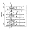
- the multi-stage transmission 214 as shown in FIG. 10 , has a construction in which a splitter 214B and a range 214C, serving as sub transmissions for changing to at least a high speed gear or a low speed gear, are connected to a main transmission 214A on its input side and output side respectively.
- a splitter gear Zm5 for switching the splitter 214B to a high speed gear is fitted such that it can rotate freely on an input shaft 322 to which the output from the engine 210 is input, and a synchronizer hub 324A constituting a synchromesh mechanism 324 is fixed to the tip end thereof.
- a drive gear Zm4, a 3 rd speed gear Zm3, a 2 nd speed gear Zm2, a 1 st speed gear Zm1, and a reverse gear ZmR, which constitute the each gear of the main transmission 214A, are fitted on the main shaft 326 located on the same axis as the input shaft 322, such that they can rotate freely, and a high range gear Zr1 for switching the range 214C to a high speed gear is fixed to the tip end thereof.
- Synchronizer hubs 324A constituting synchromesh mechanisms 324 are fixed to the main shaft 326 between the drive gear Zm4 and the 3 rd speed gear Zm3, the 2 nd speed gear Zm2 and the 1 st speed gear Zm1, and the 1 st speed gear Zm1 and the reverse gear ZmR respectively.
- a counter splitter gear Zc5, a counter drive gear Zc4, a counter 3 rd speed gear Zc3, a counter 2 nd speed gear Zc2, and a counter 1 st speed gear Zc1, which are always engaged with the splitter gear Zm5, the drive gear Zm4, the 3 rd speed gear Zm3, the 2 nd speed gear Zm2, and the 1 st speed gear Zm1 respectively, are fixed to a main counter shaft 328 arranged in parallel to the input shaft 322 and the main shaft 326.
- a counter reverse gear ZcR which is always engaged with the reverse gear ZmR via a reverse idler gear ZmR1, is fixed to the main counter shaft 328.
- a range low gear Zr2 for switching the range 214C to a low speed gear is fitted on the output shaft 330 located on the same axis as the main shaft 326, such that it can rotate freely about the output shaft 330, and a synchronizer hub 324A constituting a synchromesh mechanism 324 is fixed on one end of the output shaft 330.
- a range counter high gear Zcr1 and a range counter low gear Zcr2, which are always engaged with the range high gear Zr1 and the range low gear Zr2, are respectively fixed on a counter range shaft 332 arranged in parallel to the output shaft 330.
- a synchronizer sleeve 324B which slides backward and forward in the direction of its axis due to an actuator, which is not shown in the figure, is connected using a spline on the periphery of each of the synchronizer hubs 324A constituting the synchromesh mechanisms 324.
- a synchronizer ring which is not shown in the figure, is pressed onto the friction surface of the gear to be synchronized, and relative rotation between the synchronizing gear and the gear to be synchronized is eliminated by the friction, so that the two are synchronized.
- a multi-stage transmission 214 with such a constitution, six shift stages are formed using the main transmission 214A and the range 214C, and twelve forward shift stages and two reverse shift stages as indicated in Table 1, below are realized by shifting each of the shift stages by a half stage using the splitter 214B.
- Table 1 Shift Stage Splitter Main Transmission Range 1L L 1 L 1H H 1 L 2L L 2 L 2H H 2 L 3L L 1 H 3H H 1 H 4L L 2 H 4H H 2 H 5L L 3 H 5H H 3 H 6L L 4 H 6H H 4 H Rev L L Rev L Rev L Rev H H Rev L
- the engine 210 is fitted with a fuel injection pump 218 capable of controlling the fuel injection amount by an engine control unit 226 incorporating a microcomputer, and a rotational speed sensor 245 for detecting the engine rotational speed. Furthermore, a clutch 212 has the output shaft of a clutch booster 222 connected thereto as a clutch drive actuator, and a clutch stroke sensor 224 (operating condition detecting means) for detecting the disengagement and engagement of the clutch based on the stroke amount is fitted thereto.
- the multi-stage transmission 214 is fitted with a main actuator 230, a splitter actuator 254, and a range actuator 256, which switch the main transmission 214A, the splitter 214B, and the range 214C respectively using pneumatic pressure via a solenoid valve 228 which is controlled to open and close by a control unit 226.
- the multi-stage transmission 214 is fitted with a main position sensor 232 (switching condition detecting means), a splitter position sensor 260, and a range position sensor 262, which detect the shift stages of the main transmission 214A, the splitter 214B, and the range 214C respectively.
- the multi-stage transmission 214 is fitted with a vehicle speed sensor 234 for detecting the vehicle speed from the rotational speed of the output shaft thereof, a main rotational speed sensor 236 for detecting the rotational speed of the main counter shaft 328, and a range rotational speed sensor 268 for detecting the rotational speed of the counter range shaft 332.
- an accelerator opening sensor 240 for detecting the amount that an accelerator pedal 238 is pressed down
- a clutch pedal sensor 244 for detecting that the clutch pedal 242 is pressed
- a shift lever 246 for inputting gear change instructions for the multi-stage transmission 214.
- a twelve speed switch 246A for designating whether the splitter 214B is switched to twelve stages or not is installed in the shift lever 246.
- a display monitor 248 for displaying the shift stage of the multi-stage transmission 214, a buzzer 282 for informing gear change completion, and the like, are provided in the driver's cab.
- each of the sensors each of which constitutes an operating condition detecting device
- the processing by the control unit 226 realizes vehicle stop determination, gear change operation determination, starting changing of the sub transmission, and starting changing of the main transmission.
- FIG. 11 and FIG. 12 show the content of the control in the multi-stage transmission 214 at the time of departure of a vehicle, which is performed at predetermined intervals in the control unit 226.
- step 201 (abbreviated to "S201" in the figure, and similarly below), based on the output from the vehicle speed sensor 234, it is determined whether the vehicle is stopped or not. That is, it is determined whether the rotation of the synchronizer sleeve 324B of the synchromesh mechanism 324 in the range 214C is stopped or not. If it is determined that the vehicle is stopped, control proceeds to step 202 (Yes), while if it is determined that the vehicle is not stopped (it is moving), the processing terminates (No). It is to be noted that the processing of step 201 corresponds to the vehicle stop determination means.
- step 202 based on the output from the clutch stroke sensor 224, it is determined whether the clutch 212 is disengaged or not. If it is determined that the clutch 212 is disengaged, control proceeds to step 203 (Yes), while if it is determined that the clutch 212 is engaged, the processing terminates (No).
- step 203 based on an output from the shift lever 246, it is determined whether gear change has started or not. If it is determined that gear change has started, control proceeds to step 204 (Yes), while if it is determined that gear change has not started, the processing terminates (No).
- step 204 based on an output from the main position sensor 232, it is determined whether the main transmission 214A is in the neutral state or not. If it is determined that the main transmission 214A is in the neutral state, control proceeds to step 205 (Yes), while if it is determined that the main transmission 214A is not in the neutral state, the processing terminates (No).
- step 205 based on outputs from the main position sensor 232 and the shift lever 246, it is determined whether the range is switching or not. If it is determined that the range is switching, control proceeds to step 206 (Yes), while if it is determined that the range is not switching, the processing terminates (No). It is to be noted that the series of processing of step 201 to step 205 corresponds to the gear change operation determination means.
- step 206 in order to switch the range, a solenoid valve 228 is operated to control the drive of the range actuator 256.
- step 207 based on an output from the range position sensor 262, it is determined whether the range switching is completed or not. If it is determined that the range switching is completed, control proceeds to step 209 (Yes), while if it is determined that the range switching is not completed, control proceeds to step 208 (No).
- step 208 based on a timer incorporated in the control unit 226, it is determined whether a predetermined time has elapsed since the range switching started or not. If it is determined that the predetermined time has elapsed, control proceeds to step 209 (Yes), while if it is determined that the predetermined time has not elapsed, control returns to step 207 (No).
- step 209 in order to change the main transmission 214A, the solenoid valve 228 is operated to control the drive of the main actuator 230.
- step 210 based on the timer incorporated in the control unit 226, it is determined whether a predetermined time has elapsed since the changing of the main transmission 214A started. If it is determined that the predetermined time has elapsed, control proceeds to step 213 (Yes), while if it is determined that the predetermined time has not elapsed, control proceeds to step 211 (No).
- step 211 based on an output from the main position sensor 232, it is determined whether the changing of the main transmission 214A is completed or not. If it is determined that the changing of the main transmission 214A is completed, control proceeds to step 212 (Yes), and control goes to standby for a predetermined time. On the other hand, if it is determined that the changing of the main transmission 214A is not completed, control returns to step 210 (No).
- step 213 in order to stop the changing of the main transmission 214A and the range 214C, the operation of the solenoid valve 228 for controlling the drive of the main actuator 230 and the range actuator 256 is stopped.
- step 201 to step 213 when an operation is performed to change the gear to the drive gear while the vehicle is stopped, causing the range 214C to switch, switching of the range 214C starts prior to changing the main transmission 214A. Then, when the switching of the range 214C starts, and is then completed, changing of the main transmission 214A starts. On the other hand, when the change is not completed even though the predetermined time has elapsed since switching of the range 214C started, it is determined that a batting state has occurred in the synchromesh mechanism 324 of the range 214C, and changing of the main transmission 214A starts while the switching of the range is incomplete.
- the main transmission 214A When changing of the main transmission 214A starts, the main transmission 214A is changed in a state in which the synchronizer sleeve 324B of the synchromesh mechanism 324 in the range 214C is pushed away toward the direction of the gear to be synchronized. Then when the clutch 212 is engaged in this state, the main shaft 326 and the counter range shaft 332 rotate due to the output from the engine 210, and relative rotation occurs between them and the synchronizer sleeve 324B of the synchromesh mechanism 324 in the range 214C. As a result, the batting state in the range 214C is cancelled, thus enabling the range to be switched. Furthermore, there is also a possibility that the main shaft 326 is shaken by the shock accompanying the changing of the main transmission 214A, so that the batting state in the range 214C is cancelled.
- a gear change control apparatus of a multi-stage transmission according to the present invention can be realized by only a small variation or modification to the existing control content. Therefore, there is little possibility of human errors accompanying a change in the control content, thus enabling an increase in cost, a drop in reliability, and the like, to be kept to a minimum.
- an apparatus for controlling an automatic transmission according to the present invention has an excellent response in the case where a vehicle decelerates and is stopping, but then cancels it and tries to reaccelerate. Furthermore, it is possible to stop the vehicle smoothly even in an idle-up state. Moreover, in a multi-stage automatic transmission, even in a state in which the changing of a sub transmission does not progress smoothly, it is possible to eliminate batting states in the sub transmission by changing the main transmission. Therefore, gear changing by the automatic transmission is performed excellently in either case, and hence the controlling apparatus is extremely useful.
Applications Claiming Priority (4)
| Application Number | Priority Date | Filing Date | Title |
|---|---|---|---|
| JP2002306177A JP2004144108A (ja) | 2002-10-21 | 2002-10-21 | 多段変速機の変速制御装置 |
| JP2002313374A JP4289865B2 (ja) | 2002-10-28 | 2002-10-28 | 自動変速機の制御装置 |
| JP2002313373A JP2004150464A (ja) | 2002-10-28 | 2002-10-28 | 自動変速機の制御装置 |
| EP03756739A EP1555461B1 (de) | 2002-10-21 | 2003-10-21 | Steuerung für automatischen gangwechsler |
Related Parent Applications (1)
| Application Number | Title | Priority Date | Filing Date |
|---|---|---|---|
| EP03756739.3 Division | 2003-10-21 |
Publications (2)
| Publication Number | Publication Date |
|---|---|
| EP2194298A1 true EP2194298A1 (de) | 2010-06-09 |
| EP2194298B1 EP2194298B1 (de) | 2012-05-09 |
Family
ID=32110652
Family Applications (3)
| Application Number | Title | Priority Date | Filing Date |
|---|---|---|---|
| EP10002554A Expired - Fee Related EP2208916B1 (de) | 2002-10-21 | 2003-10-21 | Vorrichtung zur Steuerung eines Automatikgetriebes |
| EP10002553A Expired - Fee Related EP2194298B1 (de) | 2002-10-21 | 2003-10-21 | Vorrichtung zur Steuerung eines Automatikgetriebes |
| EP03756739A Expired - Fee Related EP1555461B1 (de) | 2002-10-21 | 2003-10-21 | Steuerung für automatischen gangwechsler |
Family Applications Before (1)
| Application Number | Title | Priority Date | Filing Date |
|---|---|---|---|
| EP10002554A Expired - Fee Related EP2208916B1 (de) | 2002-10-21 | 2003-10-21 | Vorrichtung zur Steuerung eines Automatikgetriebes |
Family Applications After (1)
| Application Number | Title | Priority Date | Filing Date |
|---|---|---|---|
| EP03756739A Expired - Fee Related EP1555461B1 (de) | 2002-10-21 | 2003-10-21 | Steuerung für automatischen gangwechsler |
Country Status (3)
| Country | Link |
|---|---|
| US (1) | US7261673B2 (de) |
| EP (3) | EP2208916B1 (de) |
| WO (1) | WO2004036091A1 (de) |
Families Citing this family (25)
| Publication number | Priority date | Publication date | Assignee | Title |
|---|---|---|---|---|
| EP1790546B1 (de) | 2004-07-01 | 2014-09-24 | Yamaha Hatsudoki Kabushiki Kaisha | Fahrzeug des sattelaufsitztyps |
| WO2006003879A1 (ja) | 2004-07-01 | 2006-01-12 | Yamaha Hatsudoki Kabushiki Kaisha | 作動力伝達機構および鞍乗型車両 |
| ES2456942T3 (es) | 2004-07-26 | 2014-04-24 | Yamaha Hatsudoki Kabushiki Kaisha | Controlador de cambio de vehículo del tipo de montar a horcajadas |
| JP4608298B2 (ja) | 2004-12-10 | 2011-01-12 | ヤマハ発動機株式会社 | 変速制御装置、変速制御方法及び鞍乗型車両 |
| ATE491099T1 (de) * | 2006-02-24 | 2010-12-15 | Yamaha Motor Co Ltd | Gangwechselverfahren für eine automatisierte schaltgetriebeeinheit und automatisiertes getriebe für ein fahrzeug |
| JP4789688B2 (ja) | 2006-04-18 | 2011-10-12 | ヤマハ発動機株式会社 | クラッチ用アクチュエータ、エンジンユニットおよび鞍乗型車両 |
| JP5121159B2 (ja) | 2006-04-18 | 2013-01-16 | ヤマハ発動機株式会社 | 自動変速制御装置および車両 |
| JP4873542B2 (ja) | 2006-04-18 | 2012-02-08 | ヤマハ発動機株式会社 | 自動変速制御装置および車両 |
| JP4972334B2 (ja) | 2006-04-18 | 2012-07-11 | ヤマハ発動機株式会社 | クラッチ用アクチュエータ、エンジンユニットおよび鞍乗型車両 |
| JP4873543B2 (ja) | 2006-04-18 | 2012-02-08 | ヤマハ発動機株式会社 | 自動変速制御装置および車両 |
| JP4931464B2 (ja) | 2006-04-18 | 2012-05-16 | ヤマハ発動機株式会社 | クラッチ制御装置および車両 |
| JP5164337B2 (ja) | 2006-04-18 | 2013-03-21 | ヤマハ発動機株式会社 | 自動変速制御装置および鞍乗型車両 |
| JP4863755B2 (ja) | 2006-04-18 | 2012-01-25 | ヤマハ発動機株式会社 | クラッチ用アクチュエータ、エンジンユニットおよび鞍乗型車両 |
| JP5089056B2 (ja) | 2006-02-24 | 2012-12-05 | ヤマハ発動機株式会社 | クラッチ異常検出装置、自動クラッチ装置および鞍乗型車両 |
| TWI293603B (en) | 2006-04-18 | 2008-02-21 | Yamaha Motor Co Ltd | Shift actuator, vehicle, and method of integrating vehicle |
| JP4247646B2 (ja) * | 2007-08-31 | 2009-04-02 | 三菱自動車工業株式会社 | 車両の制御装置 |
| DE102007041571A1 (de) * | 2007-09-01 | 2009-03-05 | Zf Friedrichshafen Ag | Verfahren zum Steuern und/oder Regeln einer Hybridantriebsanordnung |
| US8527162B2 (en) * | 2009-03-12 | 2013-09-03 | Toyota Jidosha Kabushiki Kaisha | Control apparatus for an automatic transmission |
| SE534581C2 (sv) * | 2010-02-01 | 2011-10-11 | Scania Cv Ab | Förfarande och system vid koppling |
| US8712651B2 (en) * | 2012-06-18 | 2014-04-29 | Chrysler Group Llc | Control strategies for a multi-mode drive system |
| DE102013003345A1 (de) * | 2013-02-27 | 2014-08-28 | Daimler Ag | Verfahren zum Lösen einer Zahn-auf-Zahn-Stellung und/oder einer Verklemmung in einer Nachschaltgruppe eines Gruppengetriebes eines Nutzkraftfahrzeugs |
| US10265068B2 (en) | 2015-12-30 | 2019-04-23 | Ethicon Llc | Surgical instruments with separable motors and motor control circuits |
| KR102286735B1 (ko) * | 2017-04-07 | 2021-08-05 | 현대자동차 주식회사 | 차량 주행 제어 장치 및 방법 |
| KR102080816B1 (ko) * | 2018-10-18 | 2020-02-24 | 엘에스엠트론 주식회사 | 농업용 작업차량의 변속기 제어장치 및 농업용 작업차량의 변속기 제어방법 |
| WO2021244729A1 (en) | 2020-06-01 | 2021-12-09 | Volvo Truck Corporation | Method and system for disengaging a clutch during engine shutdown and vehicle comprising such a system |
Citations (10)
| Publication number | Priority date | Publication date | Assignee | Title |
|---|---|---|---|---|
| JPS631840A (ja) * | 1986-06-23 | 1988-01-06 | Toyota Motor Corp | 副変速機を備えた車両用変速装置 |
| EP0449499A2 (de) * | 1990-03-26 | 1991-10-02 | Eaton Corporation | Anfahr-Steuerungsverfahren |
| US6128974A (en) * | 1999-09-03 | 2000-10-10 | Eaton Corporation | Start gear engagement control for controller-assisted, manually shifted, synchronized, compound transmission with splitter section |
| JP2001092119A (ja) | 1999-09-22 | 2001-04-06 | Toray Ind Inc | 感光性ペースト、ディスプレイおよびディスプレイ用部材 |
| EP1092894A2 (de) * | 1999-10-12 | 2001-04-18 | Eaton Corporation | Anfahrtssteuerung für ein servounterstütztes, manuell geschaltetes Splitter-Verbundgetriebe |
| JP2001165294A (ja) | 1999-12-14 | 2001-06-19 | Nissan Diesel Motor Co Ltd | 車両の自動変速装置 |
| JP2001227630A (ja) | 2000-02-15 | 2001-08-24 | Nissan Diesel Motor Co Ltd | 車両の自動変速装置 |
| JP2001241542A (ja) * | 2000-02-25 | 2001-09-07 | Mitsubishi Motors Corp | 副変速機の変速制御装置 |
| JP2001254813A (ja) * | 2000-03-14 | 2001-09-21 | Isuzu Motors Ltd | 車両の変速装置 |
| JP2002283882A (ja) * | 2001-03-28 | 2002-10-03 | Nissan Diesel Motor Co Ltd | 車両の自動変速装置 |
Family Cites Families (36)
| Publication number | Priority date | Publication date | Assignee | Title |
|---|---|---|---|---|
| JPS52147936A (en) | 1976-06-02 | 1977-12-08 | Mitsubishi Electric Corp | Random logic circuit using reading exclusive memory |
| JPS5481461A (en) * | 1977-12-08 | 1979-06-28 | Daikin Mfg Co Ltd | Fully automatic control method and apparatus for gear transmission |
| JPS58196237A (ja) | 1982-05-13 | 1983-11-15 | Daicel Chem Ind Ltd | ポリカ−ボネ−ト成形品の表面処理法 |
| JPS59113551A (ja) | 1982-12-21 | 1984-06-30 | Mitsubishi Electric Corp | 磁気記録再生装置 |
| JPS59113551U (ja) * | 1983-01-21 | 1984-07-31 | トヨタ自動車株式会社 | 電子制御式自動変速機 |
| JPS6017781A (ja) | 1983-07-12 | 1985-01-29 | Fuji Xerox Co Ltd | 除電装置 |
| JPS60103748A (ja) | 1983-11-09 | 1985-06-08 | Sony Corp | デイジタル信号伝送方式 |
| JPS60108819A (ja) | 1983-11-18 | 1985-06-14 | Matsushita Electric Ind Co Ltd | 光学プリンタ |
| JPS60103748U (ja) * | 1983-12-22 | 1985-07-15 | 日産ディーゼル工業株式会社 | 車両の自動変速装置 |
| JPS6163369A (ja) | 1984-09-04 | 1986-04-01 | Daihen Corp | 分離形ア−ク溶接機 |
| JPS61146334A (ja) | 1984-12-17 | 1986-07-04 | Mikasa Kagaku Kogyo Kk | 多層粉粒体の製法 |
| JPS61179250A (ja) | 1985-02-04 | 1986-08-11 | New Japan Chem Co Ltd | 塩化ビニル系樹脂組成物 |
| JPH0434105Y2 (de) * | 1985-02-13 | 1992-08-14 | ||
| WO1986005747A1 (en) * | 1985-03-29 | 1986-10-09 | Mitsubishi Jidosha Kogyo Kabushiki Kaisha | Starting control apparatus for automatic speed change gears |
| JPS6217436A (ja) | 1985-07-15 | 1987-01-26 | Horikiri Bane Seisakusho:Kk | コイルばね |
| JPH0519234Y2 (de) * | 1985-07-18 | 1993-05-20 | ||
| JPS62218245A (ja) * | 1986-03-20 | 1987-09-25 | Mazda Motor Corp | 車両用自動変速機の制御装置 |
| JPS62227824A (ja) * | 1986-03-28 | 1987-10-06 | Isuzu Motors Ltd | 自動クラツチ搭載車両のクラツチ制御装置 |
| JPS639922A (ja) | 1986-06-30 | 1988-01-16 | Toshiba Corp | ウエハ接合装置 |
| JPS6334249A (ja) * | 1986-07-29 | 1988-02-13 | Toyota Autom Loom Works Ltd | 車両のギアシフト制御装置 |
| JPH01114328U (de) * | 1988-01-28 | 1989-08-01 | ||
| JPH02203535A (ja) | 1989-02-01 | 1990-08-13 | Toshiba Corp | 半導体装置の製造方法 |
| JPH0487841A (ja) * | 1990-07-31 | 1992-03-19 | Hino Motors Ltd | 半自動変速制御装置 |
| JPH0622658A (ja) | 1991-01-04 | 1994-02-01 | Iseki & Co Ltd | ラベンダー胚様体カルスの製造方法 |
| JPH0622658U (ja) * | 1992-08-24 | 1994-03-25 | 日産ディーゼル工業株式会社 | 変速機の変速制御装置 |
| GB9312013D0 (en) * | 1993-06-10 | 1993-07-28 | Eaton Corp | Clutch disengage logic |
| JP3157656B2 (ja) | 1993-07-30 | 2001-04-16 | 日産ディーゼル工業株式会社 | 車両の自動変速装置 |
| JPH07236884A (ja) | 1994-02-28 | 1995-09-12 | Toshiharu Tsukada | 水の浄化及び滅菌処理装置 |
| JP3198886B2 (ja) * | 1995-09-14 | 2001-08-13 | 三菱自動車工業株式会社 | 変速装置 |
| JP2629659B2 (ja) | 1996-04-22 | 1997-07-09 | 株式会社ニコン | 回路パターン形成方法 |
| JPH11509612A (ja) * | 1996-05-11 | 1999-08-24 | ルーク ゲトリーベ−ジステーメ ゲゼルシャフト ミット ベシュレンクテル ハフツング | 自動車 |
| JPH11354349A (ja) | 1998-06-08 | 1999-12-24 | Sony Corp | ロータリトランス製造装置 |
| JP3327257B2 (ja) | 1998-06-18 | 2002-09-24 | 日本電気株式会社 | ネッティングサービスシステム |
| JP2000037097A (ja) | 1998-07-15 | 2000-02-02 | Matsushita Seiko Co Ltd | 風力発電装置 |
| JP4090213B2 (ja) * | 2001-03-28 | 2008-05-28 | 日産ディーゼル工業株式会社 | 機械式変速機の制御装置 |
| JP2002295517A (ja) | 2001-03-29 | 2002-10-09 | Aisin Seiki Co Ltd | クラッチの制御装置 |
-
2003
- 2003-10-21 EP EP10002554A patent/EP2208916B1/de not_active Expired - Fee Related
- 2003-10-21 EP EP10002553A patent/EP2194298B1/de not_active Expired - Fee Related
- 2003-10-21 US US10/531,917 patent/US7261673B2/en not_active Expired - Fee Related
- 2003-10-21 EP EP03756739A patent/EP1555461B1/de not_active Expired - Fee Related
- 2003-10-21 WO PCT/JP2003/013445 patent/WO2004036091A1/ja active Application Filing
Patent Citations (10)
| Publication number | Priority date | Publication date | Assignee | Title |
|---|---|---|---|---|
| JPS631840A (ja) * | 1986-06-23 | 1988-01-06 | Toyota Motor Corp | 副変速機を備えた車両用変速装置 |
| EP0449499A2 (de) * | 1990-03-26 | 1991-10-02 | Eaton Corporation | Anfahr-Steuerungsverfahren |
| US6128974A (en) * | 1999-09-03 | 2000-10-10 | Eaton Corporation | Start gear engagement control for controller-assisted, manually shifted, synchronized, compound transmission with splitter section |
| JP2001092119A (ja) | 1999-09-22 | 2001-04-06 | Toray Ind Inc | 感光性ペースト、ディスプレイおよびディスプレイ用部材 |
| EP1092894A2 (de) * | 1999-10-12 | 2001-04-18 | Eaton Corporation | Anfahrtssteuerung für ein servounterstütztes, manuell geschaltetes Splitter-Verbundgetriebe |
| JP2001165294A (ja) | 1999-12-14 | 2001-06-19 | Nissan Diesel Motor Co Ltd | 車両の自動変速装置 |
| JP2001227630A (ja) | 2000-02-15 | 2001-08-24 | Nissan Diesel Motor Co Ltd | 車両の自動変速装置 |
| JP2001241542A (ja) * | 2000-02-25 | 2001-09-07 | Mitsubishi Motors Corp | 副変速機の変速制御装置 |
| JP2001254813A (ja) * | 2000-03-14 | 2001-09-21 | Isuzu Motors Ltd | 車両の変速装置 |
| JP2002283882A (ja) * | 2001-03-28 | 2002-10-03 | Nissan Diesel Motor Co Ltd | 車両の自動変速装置 |
Also Published As
| Publication number | Publication date |
|---|---|
| EP2208916B1 (de) | 2012-05-16 |
| EP1555461A1 (de) | 2005-07-20 |
| US20070087897A1 (en) | 2007-04-19 |
| US7261673B2 (en) | 2007-08-28 |
| EP1555461B1 (de) | 2011-11-16 |
| EP2194298B1 (de) | 2012-05-09 |
| EP1555461A4 (de) | 2010-01-06 |
| WO2004036091A1 (ja) | 2004-04-29 |
| EP2208916A1 (de) | 2010-07-21 |
Similar Documents
| Publication | Publication Date | Title |
|---|---|---|
| EP2194298B1 (de) | Vorrichtung zur Steuerung eines Automatikgetriebes | |
| EP2035727B1 (de) | System und verfahren zum anpassen der motordrehzahl an die fahrzeuggeschwindigkeit mit einem handschaltgetriebe | |
| KR100316750B1 (ko) | 변속제어방법및장치 | |
| US8070652B2 (en) | Method for overcoming tooth butt conditions when engaging gears in transmissions | |
| US7503876B2 (en) | Apparatus for and method of controlling automatic transmission | |
| JP3826888B2 (ja) | 多段式自動変速機の変速制御装置 | |
| JPH0868460A (ja) | 変速装置のシフト制御方法および装置 | |
| US6254508B1 (en) | Engine torque control during multiple speed changes of an automatic transmission | |
| JPH08268123A (ja) | ニュートラル到達へのシフト制御方法及びその装置 | |
| JP2003074683A (ja) | 車輌の制御装置 | |
| EP1174646A2 (de) | Steuerungsverfahren und Steuerung für ein automatisches Getriebe | |
| JP2004144108A (ja) | 多段変速機の変速制御装置 | |
| EP1400732A2 (de) | Steuersystem und -verfahren für Automatikgetriebe | |
| JPH08184368A (ja) | 車両用油圧作動式変速機の油圧制御装置 | |
| JP4529334B2 (ja) | 車輌の制御装置 | |
| JP4289865B2 (ja) | 自動変速機の制御装置 | |
| JPH0243048B2 (de) | ||
| JP3622355B2 (ja) | 自動変速機の制御装置 | |
| JPH08233090A (ja) | 油圧作動式変速機の制御装置 | |
| JP2001271921A (ja) | 変速機とその自動変速制御方法 | |
| JPH0533805Y2 (de) | ||
| JPS6226131A (ja) | 自動トランスミツシヨン | |
| JPH0320581Y2 (de) | ||
| JPH032414Y2 (de) | ||
| JPH02229922A (ja) | クラッチの制御装置および方法 |
Legal Events
| Date | Code | Title | Description |
|---|---|---|---|
| PUAI | Public reference made under article 153(3) epc to a published international application that has entered the european phase |
Free format text: ORIGINAL CODE: 0009012 |
|
| AC | Divisional application: reference to earlier application |
Ref document number: 1555461 Country of ref document: EP Kind code of ref document: P |
|
| AK | Designated contracting states |
Kind code of ref document: A1 Designated state(s): DE FR |
|
| 17P | Request for examination filed |
Effective date: 20101209 |
|
| 17Q | First examination report despatched |
Effective date: 20110525 |
|
| GRAP | Despatch of communication of intention to grant a patent |
Free format text: ORIGINAL CODE: EPIDOSNIGR1 |
|
| RIC1 | Information provided on ipc code assigned before grant |
Ipc: B60W 30/18 20060101ALN20111019BHEP Ipc: B60W 10/02 20060101ALN20111019BHEP Ipc: B60W 10/10 20060101ALN20111019BHEP Ipc: F16H 61/70 20060101AFI20111019BHEP Ipc: F16H 63/46 20060101ALN20111019BHEP Ipc: B60W 10/06 20060101ALN20111019BHEP |
|
| RIN1 | Information on inventor provided before grant (corrected) |
Inventor name: HAYASHI, AKIHISA Inventor name: ISOBE, OSAMU Inventor name: KITAMURA, TOSHIO Inventor name: OKAMOTO, ISAO Inventor name: ICHIKAWA, YUUICHI |
|
| GRAS | Grant fee paid |
Free format text: ORIGINAL CODE: EPIDOSNIGR3 |
|
| GRAA | (expected) grant |
Free format text: ORIGINAL CODE: 0009210 |
|
| AC | Divisional application: reference to earlier application |
Ref document number: 1555461 Country of ref document: EP Kind code of ref document: P |
|
| AK | Designated contracting states |
Kind code of ref document: B1 Designated state(s): DE FR |
|
| REG | Reference to a national code |
Ref country code: DE Ref legal event code: R096 Ref document number: 60340936 Country of ref document: DE Effective date: 20120705 |
|
| PLBE | No opposition filed within time limit |
Free format text: ORIGINAL CODE: 0009261 |
|
| STAA | Information on the status of an ep patent application or granted ep patent |
Free format text: STATUS: NO OPPOSITION FILED WITHIN TIME LIMIT |
|
| 26N | No opposition filed |
Effective date: 20130212 |
|
| REG | Reference to a national code |
Ref country code: DE Ref legal event code: R097 Ref document number: 60340936 Country of ref document: DE Effective date: 20130212 |
|
| PGFP | Annual fee paid to national office [announced via postgrant information from national office to epo] |
Ref country code: FR Payment date: 20141029 Year of fee payment: 12 Ref country code: DE Payment date: 20141010 Year of fee payment: 12 |
|
| REG | Reference to a national code |
Ref country code: DE Ref legal event code: R119 Ref document number: 60340936 Country of ref document: DE |
|
| PG25 | Lapsed in a contracting state [announced via postgrant information from national office to epo] |
Ref country code: DE Free format text: LAPSE BECAUSE OF NON-PAYMENT OF DUE FEES Effective date: 20160503 |
|
| REG | Reference to a national code |
Ref country code: FR Ref legal event code: ST Effective date: 20160630 |
|
| PG25 | Lapsed in a contracting state [announced via postgrant information from national office to epo] |
Ref country code: FR Free format text: LAPSE BECAUSE OF NON-PAYMENT OF DUE FEES Effective date: 20151102 |