EP1092894A2 - Anfahrtssteuerung für ein servounterstütztes, manuell geschaltetes Splitter-Verbundgetriebe - Google Patents
Anfahrtssteuerung für ein servounterstütztes, manuell geschaltetes Splitter-Verbundgetriebe Download PDFInfo
- Publication number
- EP1092894A2 EP1092894A2 EP00121888A EP00121888A EP1092894A2 EP 1092894 A2 EP1092894 A2 EP 1092894A2 EP 00121888 A EP00121888 A EP 00121888A EP 00121888 A EP00121888 A EP 00121888A EP 1092894 A2 EP1092894 A2 EP 1092894A2
- Authority
- EP
- European Patent Office
- Prior art keywords
- splitter
- section
- ratio
- clutch
- main transmission
- Prior art date
- Legal status (The legal status is an assumption and is not a legal conclusion. Google has not performed a legal analysis and makes no representation as to the accuracy of the status listed.)
- Granted
Links
Images


Classifications
-
- F—MECHANICAL ENGINEERING; LIGHTING; HEATING; WEAPONS; BLASTING
- F16—ENGINEERING ELEMENTS AND UNITS; GENERAL MEASURES FOR PRODUCING AND MAINTAINING EFFECTIVE FUNCTIONING OF MACHINES OR INSTALLATIONS; THERMAL INSULATION IN GENERAL
- F16H—GEARING
- F16H61/00—Control functions within control units of change-speed- or reversing-gearings for conveying rotary motion ; Control of exclusively fluid gearing, friction gearing, gearings with endless flexible members or other particular types of gearing
- F16H61/70—Control functions within control units of change-speed- or reversing-gearings for conveying rotary motion ; Control of exclusively fluid gearing, friction gearing, gearings with endless flexible members or other particular types of gearing specially adapted for change-speed gearing in group arrangement, i.e. with separate change-speed gear trains arranged in series, e.g. range or overdrive-type gearing arrangements
- F16H61/702—Control functions within control units of change-speed- or reversing-gearings for conveying rotary motion ; Control of exclusively fluid gearing, friction gearing, gearings with endless flexible members or other particular types of gearing specially adapted for change-speed gearing in group arrangement, i.e. with separate change-speed gear trains arranged in series, e.g. range or overdrive-type gearing arrangements using electric or electrohydraulic control means
-
- F—MECHANICAL ENGINEERING; LIGHTING; HEATING; WEAPONS; BLASTING
- F16—ENGINEERING ELEMENTS AND UNITS; GENERAL MEASURES FOR PRODUCING AND MAINTAINING EFFECTIVE FUNCTIONING OF MACHINES OR INSTALLATIONS; THERMAL INSULATION IN GENERAL
- F16H—GEARING
- F16H59/00—Control inputs to control units of change-speed-, or reversing-gearings for conveying rotary motion
- F16H59/68—Inputs being a function of gearing status
- F16H2059/6823—Sensing neutral state of the transmission
-
- F—MECHANICAL ENGINEERING; LIGHTING; HEATING; WEAPONS; BLASTING
- F16—ENGINEERING ELEMENTS AND UNITS; GENERAL MEASURES FOR PRODUCING AND MAINTAINING EFFECTIVE FUNCTIONING OF MACHINES OR INSTALLATIONS; THERMAL INSULATION IN GENERAL
- F16H—GEARING
- F16H61/00—Control functions within control units of change-speed- or reversing-gearings for conveying rotary motion ; Control of exclusively fluid gearing, friction gearing, gearings with endless flexible members or other particular types of gearing
- F16H61/02—Control functions within control units of change-speed- or reversing-gearings for conveying rotary motion ; Control of exclusively fluid gearing, friction gearing, gearings with endless flexible members or other particular types of gearing characterised by the signals used
- F16H61/0202—Control functions within control units of change-speed- or reversing-gearings for conveying rotary motion ; Control of exclusively fluid gearing, friction gearing, gearings with endless flexible members or other particular types of gearing characterised by the signals used the signals being electric
- F16H61/0204—Control functions within control units of change-speed- or reversing-gearings for conveying rotary motion ; Control of exclusively fluid gearing, friction gearing, gearings with endless flexible members or other particular types of gearing characterised by the signals used the signals being electric for gearshift control, e.g. control functions for performing shifting or generation of shift signal
- F16H61/0213—Control functions within control units of change-speed- or reversing-gearings for conveying rotary motion ; Control of exclusively fluid gearing, friction gearing, gearings with endless flexible members or other particular types of gearing characterised by the signals used the signals being electric for gearshift control, e.g. control functions for performing shifting or generation of shift signal characterised by the method for generating shift signals
- F16H2061/023—Drive-off gear selection, i.e. optimising gear ratio for drive off of a vehicle
-
- F—MECHANICAL ENGINEERING; LIGHTING; HEATING; WEAPONS; BLASTING
- F16—ENGINEERING ELEMENTS AND UNITS; GENERAL MEASURES FOR PRODUCING AND MAINTAINING EFFECTIVE FUNCTIONING OF MACHINES OR INSTALLATIONS; THERMAL INSULATION IN GENERAL
- F16H—GEARING
- F16H2306/00—Shifting
- F16H2306/40—Shifting activities
- F16H2306/46—Uncoupling of current gear
-
- F—MECHANICAL ENGINEERING; LIGHTING; HEATING; WEAPONS; BLASTING
- F16—ENGINEERING ELEMENTS AND UNITS; GENERAL MEASURES FOR PRODUCING AND MAINTAINING EFFECTIVE FUNCTIONING OF MACHINES OR INSTALLATIONS; THERMAL INSULATION IN GENERAL
- F16H—GEARING
- F16H2312/00—Driving activities
- F16H2312/02—Driving off
- F16H2312/022—Preparing to drive off
-
- F—MECHANICAL ENGINEERING; LIGHTING; HEATING; WEAPONS; BLASTING
- F16—ENGINEERING ELEMENTS AND UNITS; GENERAL MEASURES FOR PRODUCING AND MAINTAINING EFFECTIVE FUNCTIONING OF MACHINES OR INSTALLATIONS; THERMAL INSULATION IN GENERAL
- F16H—GEARING
- F16H59/00—Control inputs to control units of change-speed-, or reversing-gearings for conveying rotary motion
- F16H59/36—Inputs being a function of speed
- F16H59/44—Inputs being a function of speed dependent on machine speed of the machine, e.g. the vehicle
-
- F—MECHANICAL ENGINEERING; LIGHTING; HEATING; WEAPONS; BLASTING
- F16—ENGINEERING ELEMENTS AND UNITS; GENERAL MEASURES FOR PRODUCING AND MAINTAINING EFFECTIVE FUNCTIONING OF MACHINES OR INSTALLATIONS; THERMAL INSULATION IN GENERAL
- F16H—GEARING
- F16H61/00—Control functions within control units of change-speed- or reversing-gearings for conveying rotary motion ; Control of exclusively fluid gearing, friction gearing, gearings with endless flexible members or other particular types of gearing
- F16H61/70—Control functions within control units of change-speed- or reversing-gearings for conveying rotary motion ; Control of exclusively fluid gearing, friction gearing, gearings with endless flexible members or other particular types of gearing specially adapted for change-speed gearing in group arrangement, i.e. with separate change-speed gear trains arranged in series, e.g. range or overdrive-type gearing arrangements
-
- Y—GENERAL TAGGING OF NEW TECHNOLOGICAL DEVELOPMENTS; GENERAL TAGGING OF CROSS-SECTIONAL TECHNOLOGIES SPANNING OVER SEVERAL SECTIONS OF THE IPC; TECHNICAL SUBJECTS COVERED BY FORMER USPC CROSS-REFERENCE ART COLLECTIONS [XRACs] AND DIGESTS
- Y10—TECHNICAL SUBJECTS COVERED BY FORMER USPC
- Y10S—TECHNICAL SUBJECTS COVERED BY FORMER USPC CROSS-REFERENCE ART COLLECTIONS [XRACs] AND DIGESTS
- Y10S477/00—Interrelated power delivery controls, including engine control
- Y10S477/908—In series transmission
-
- Y—GENERAL TAGGING OF NEW TECHNOLOGICAL DEVELOPMENTS; GENERAL TAGGING OF CROSS-SECTIONAL TECHNOLOGIES SPANNING OVER SEVERAL SECTIONS OF THE IPC; TECHNICAL SUBJECTS COVERED BY FORMER USPC CROSS-REFERENCE ART COLLECTIONS [XRACs] AND DIGESTS
- Y10—TECHNICAL SUBJECTS COVERED BY FORMER USPC
- Y10T—TECHNICAL SUBJECTS COVERED BY FORMER US CLASSIFICATION
- Y10T74/00—Machine element or mechanism
- Y10T74/19—Gearing
- Y10T74/19219—Interchangeably locked
- Y10T74/19251—Control mechanism
Definitions
- the present invention relates to a controller-assisted, manually shifted vehicular transmission system including a splitter-type compound transmission.
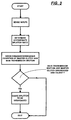
- the system will sense very low vehicle speed, master clutch disengagement, and a shift into main section neutral and will automatically shift the splitter section into neutral, allowing the main section to be engaged into a target start ratio without excess wear on, or the need for, a clutch brake.
- the splitter section Upon sensing completion of the main section shift into a target start ratio, the splitter section will be caused to engage in an appropriate splitter ratio.
- a splitter or combined splitter-and-range-type compound synchronized transmission for heavy-duty vehicles is provided with controls and actuators for manually performed main section start ratio engagement shifting without requiring excessive wear on or the use of a clutch brake.
- ECU electronice control unit
- Clutch brakes also called start brakes, are known in the prior art, as may be seen by reference to U.S. Pat. No. 5,713,443, the disclosure of which is incorporated herein by reference. Clutch brakes are used to retard spinning of the transmission input shaft caused by inertia and/or random clutch engagement when the master clutch is fully disengaged to allow engaging of a start ratio in a stopped or substantially stopped vehicle. In manual systems, actuation of the clutch brake is often by overtravel of the clutch pedal.
- the provision, installation, maintenance and/or adjustment of a clutch brake can involve considerable time and expense.
- the clutch brake can be misused as an upshift brake to allow for more rapid dynamic upshifts, which may result in excessive wear and/or damage to the clutch brake.
- a preferred embodiment of the present invention involves a computer-assisted mechanical compound transmission system wherein the main section is provided with jaw clutches and is shifted by a manually controlled shift lever, and the engine is fueled and/or the auxiliary sections are shifted by actuators at least partially controlled by an ECU to enhance shifting.
- the ECU uses sensed and/or calculated inputs indicative of system operating parameters, such as vehicle speed, master clutch condition, position and/or rate of change of position of the shift lever, engaged gear ratio, engine speed, output shaft speed and/or throttle pedal position, to assist shifting by controlling the three-position splitter actuator shift actuator and, preferably, also engine fueling and/or operation of the range shift actuator.
- the drawbacks of the prior art are minimized or overcome by the provision of a control method/system that includes logic rules or an algorithm using a number of inputs to determine when the vehicle is at rest, the master clutch is disengaged and the main transmission section is in neutral, and to automatically cause the splitter section to be shifted into splitter section neutral.
- This will minimize the wear on and/or the need for a clutch brake by reducing the inertia of the rotating elements being clutched by the main section jaw clutches, allowing the main section to be engaged in a start ratio considerably out of synchronous, while not causing an objectionable amount of wear or harshness to the vehicle operator.
- a computer-assisted (i.e. , microprocessor-based, controller-assisted) vehicular compound mechanical transmission system 10, particularly well suited to utilize the shift control of the present invention, may be seen by reference to Figs. 1-2.
- System 10 is of the type commonly utilized in heavy-duty vehicles, such as the conventional tractors of tractor/semi-trailer vehicles, and includes an engine, typically a diesel engine 12, a master friction clutch 14 contained within a clutch housing, a multiple-speed compound transmission 16, and a drive axle assembly (not shown).
- the transmission 16 includes an output shaft 20 drivingly coupled to a vehicle drive shaft by a universal joint for driving the drive axle assembly.
- the transmission 16 is housed within a transmission housing to which is directly mounted the shift tower of the shift lever assembly 30.
- the present system is equally applicable to remotely mounted shift levers, as are used in cab-over-engine types of vehicles.
- system 10 is illustrated with a manual shift lever and manual clutch pedal, this is for illustrative purposes only and not intended to be limiting.
- the shift lever assembly 30 will include a shift finger or the like (not shown) extending downwardly into a shifting mechanism, such as a multiple-rail shift bar housing assembly or a single shift shaft assembly, as is well known in the prior art and as is illustrated in aforementioned U.S. Pats. No. 4,455,883; 4,550,627; 4,920,815 and 5,272,931.
- Shifting of transmission 16 comprising non-synchronized main section 16A coupled in series to auxiliary section 16B, is semi-automatically implemented/assisted by the vehicular transmission system 10.
- Main section 16A includes an input shaft 26, which is operatively coupled to the drive or crank shaft 28 of the vehicle engine 12 by master clutch 14, and output shaft 20 of auxiliary section 16B is operatively coupled, commonly by means of a drive shaft, to the drive wheels of the vehicle.
- the auxiliary section 16B is a splitter type, preferably a combined range-and-splitter type, as illustrated in U.S. Pats. No. 4,754,665 and 5,390,561.
- the change-gear ratios available from main transmission section 16 are manually selectable by manually positioning the shift lever according to the shift pattern prescribed to engage the particular desired gear ratio.
- the system may include sensors 30 (for sensing engine rotational speed (ES)), 32 (for sensing input shaft rotational speed (IS)), and 34 (for sensing output shaft rotational speed (OS)), and providing signals indicative thereof.
- ES engine rotational speed
- IS input shaft rotational speed
- OS output shaft rotational speed
- Engine 12 is electronically controlled, including an electronic controller 36 communicating over an electronic data link (DL) operating under an industry standard protocol such as SAE J-1922, SAE J-1939, ISO 11898 or the like.
- Throttle position (operator demand) is a desirable parameter for selecting shifting points and in other control logic.
- a separate throttle position sensor (not shown) may be provided or throttle position (THL) may be sensed from the data link.
- Gross engine torque (T EG ) and base engine friction torque (T BEF ) also are available on the data link.
- a manual clutch pedal 40 controls the master clutch 14, and a sensor 42 provides a signal (CL) indicative of clutch-engaged or -disengaged condition.
- CL signal indicative of clutch-engaged or -disengaged condition.
- the condition of the clutch also may be determined by comparing engine speed to input shaft speed if both signals are available.
- An auxiliary section actuator 44 including a range shift actuator and a splitter actuator 46 is provided for operating the range clutch and the splitter section clutch in accordance with command output signals from ECU 48.
- a clutch brake 27 may be used to selectively retard the rotational speed in input shaft 26.
- Clutch brakes are typically relatively low-capacity friction devices operated automatically or by overtravel of the clutch pedal. The clutch brake is intended for use during engaging a start ratio with the vehicle at rest.
- Clutch pedal 40 has anormal range of travel 40A for engaging and disengaging the normally engaged clutch 14 and an overtravel range 40B by which the driver may select operation of the clutch brake 27.
- a mechanical switch 40C may be used to sense overtravel of clutch pedal 40.
- the system includes a control unit or ECU 48, preferably a microprocessor-based control unit of the type illustrated in U.S. Pats. No. 4,595,986; 4,361,056 and 5,335,566, the disclosures of which are incorporated herein by reference, for receiving input signals 68 and processing same according to predetermined logic rules to issue command ouptut signals 70 to system actuators, such as the splitter section actuator 46, the engine controller 36, the range shift actuator and/or a display.
- system actuators such as the splitter section actuator 46, the engine controller 36, the range shift actuator and/or a display.
- a separate system controller may be utilized, or the engine controller, ECU 36, communicating over an electronic data link, may be utilized.
- the splitter actuator 46 is, preferably, a three-position device, allowing a selectable and maintainable splitter-section-neutral.
- a "pseudo" splitter-neutral may be provided by de-energizing the splitter actuator when the splitter clutch is in an intermediate, non-engaged position.
- the structure of the 10-forward-speed combined range-and-splitter-type synchronized transmission 16 is schematically illustrated in Fig. 2.
- Transmissions of this general type are disclosed in aforementioned U.S. Pats. No. 5,000,060; 5,370,013 and 5,390,561.
- Transmission 16 includes a non-synchronized main section 16A and an auxiliary section 14B, both contained within a housing including a forward end wall 16C, which may be defined by the clutch housing, and a rearward end wall 16D, but (in this particular embodiment) not an intermediate wall.
- Input shaft 26 carries input gear 76 fixed for rotation therewith.
- the mainshaft 82 carries synchronized mainshaft clutches 84 and 86, and the mainshaft splitter clutch 88. Shift forks (not shown) are provided for shifting clutches 84 and 86 and are controlled by shift lever 31 acting on the shift assembly 32.
- Mainshaft 82 is independently rotatable relative to input shaft 26 and output shaft 20 and preferably is free for limited radial movement relative thereto.
- clutches 84 and 86 are double-acting devices movable fore and aft from the centered positions thereof to engage a selected main section ratio.
- a first jaw clutch 84A is defined by a first array of clutch teeth 84B carried by the leftward end of clutch member 84, which are engageable with a second array of clutch teeth 84C carried by input gear 78.
- the main section 16A includes two substantially identical main section countershaft assemblies 94, each comprising a main section countershaft 96 carrying countershaft gears 98, 100, 102, 104 and 106 fixed thereto. Gear pairs 98, 102, 104 and 106 are constantly meshed with input gear 76, mainshaft gears 108 and 110 and an idler gear (not shown), which is meshed with reverse mainshaft gear 112, respectively.
- Countershaft gear 100 is provided for driving a PTO or the like.
- the auxiliary section 16B of transmission 16 includes a splitter section 16E and a range section 16F.
- Auxiliary section 16B includes two substantially identical auxiliary countershaft assemblies 114, each including an auxiliary countershaft 116 carrying auxiliary countershaft gears 118, 120 and 122 for rotation therewith.
- Auxiliary countershaft gear pairs 118, 120 and 122 are constantly meshed with splitter gear 124, splitter/range gear 126 and range gear 128, respectively.
- Splitter clutch 88 is fixed to mainshaft 82 for selectively clutching either gear 124 or 126 thereto, while synchronized range clutch 130 is fixed to output shaft 20 for selectively clutching either gear 126 or gear 128 thereto.
- the splitter jaw clutch 88 is a double-sided, non-synchronized clutch assembly which may be selectively positioned in the rightwardmost or leftwardmost positions for engaging either gear 126 or gear 124, respectively, to the mainshaft 82 or to an intermediate position wherein neither gear 124 or 126 is clutched to the main shaft.
- Splitter jaw clutch 88 is axially positioned by means of a shift fork 98 controlled by a three-position actuator, such as a piston actuator, which is responsive to a driver selection switch such as a button or the like on the shift knob, as is known in the prior art and to control signals from ECU 48 (see U.S. Pat. No. 5,661,998).
- Two-position synchronized range clutch assembly 130 is a two-position clutch which may be selectively positioned in either the rightwardmost or leftwardmost positions thereof for selectively clutching either gear 128 or 126, respectively, to output shaft 20.
- Clutch assembly 130 is positioned by means of a shift fork (not shown) operated by means of a two-position piston device.
- Either piston actuator may be replaced by a functionally equivalent actuator, such as a ball screw mechanism, ball ramp mechanism or the like.
- auxiliary transmission section 16B is a three-layer auxiliary section of the combined range and splitter type providing four selectable speeds or drive ratios between the input (mainshaft 82) and output (output shaft 20) thereof.
- the main section 16A provides a reverse and three potentially selectable forward speeds.
- one of the selectable main section forward gear ratios, the low-speed gear ratios associated with mainshaft gear 110, is not utilized in the high range.
- transmission 16 is properly designated as a "(2 + 1) ⁇ (2 ⁇ 2)" type transmission providing nine or ten selectable forward speeds, depending upon the desirability and practicality of splitting the low gear ratio.
- splitter shifting of transmission 16 is accomplished responsive to initiation by a vehicle operator-actuated splitter button or the like, usually a button located at the shift lever knob, while operation of the range clutch shifting assembly is an automatic response to movement of the gear shift lever between the central and rightwardmost legs of the shift pattern, as illustrated in Fig. 2.
- splitter shifting may be automated (see U.S. Pat. No. 5,435,212).
- Range shift devices of this general type are known in the prior art and may be seen by reference to aforementioned U.S. Pats. No. 3,429,202; 4,455,883; 4,561,325 and 4,663,725.
- the shift knob will include a sensor or an intent-to-shift button by which the driver will indicate that he intends to initiate a lever shift sequence.
- the controller Upon receiving the intent-to-shift signal, the controller will issue commands to the engine controller to relieve torque lock by fuel manipulations and possibly to auxiliary section actuator to preselect the required splitter shift. This will allow easy shifting from the engaged ratio into neutral without operator throttle manipulation or clutch disengagement. Engine manipulations to relieve torque lock without requiring clutch disengagement are described in greater detail in aforementioned U.S. Pats. No. 4,850,236 and 5,105,357.
- the interengaging clutch teeth provided on splitter clutch 88 and on splitter gear 124 and splitter/range gear 126 are of a relatively large backlash (i.e., about .020-.060 inches for a 3.6-inch pitch diameter clutch), which will assure that almost any attempted splitter shift under full force will be completed.
- Actuator assembly 44 may be a conventional three-position actuator (see U.S. Pat. No. 5,054,591, the disclosure of which is incorporated herein by reference) or an actuator of the type illustrated in U.S. Pat. No. 5,682,790 or 5,661,998 (the disclosures of which are incorporated herein by reference), wherein pulse width modulation of a selectively pressurized and exhausted chamber 144 may be used to achieve the three splitter positions (L, N, H) of the shift fork.
- the splitter clutch actuator 44 will be capable of applying a variable force, such as by pulse width modulation, of supply pressure.
- a force lesser than full force may be utilized when disengaging and/or when synchronous conditions cannot be verified.
- the position of the shift lever or other shifting mechanism controlled thereby may be sensed by a position sensor device.
- Various positioning sensing assemblies are known in the prior art, with a preferred type illustrated in U.S. Pat. No. 5,743,143, assigned to the assignee of this application, the disclosure of which is incorporated herein by reference.
- the master clutch disengaged and the main section in neutral
- the splitter section is shifted to and maintained in splitter-neutral. After the main section is engaged in an appropriate start ratio, the splitter section is then engaged in the appropriate splitter ratio.
- the main shaft is disconnected from the input shaft 26 and associated gearing (gears 76, 98, 102, 104, 106, 108, 110 and 112) and also from the output shaft 20 and its associated gearing (gears 118, 120, 122, 124, 126 and 128).
- the clutches would be exposed to the inertia of the countershafts, the gearing, the input shaft and certain master clutch components. This inertia would be around 0.21 pound-feet/second 2 , while with the present invention, the inertia of the main shaft, main shaft washers and portions of the synchronizers carried by the main shaft is only about 0.007 pound-feet/second 2 .
- a main section jaw clutch associated with a target start ratio may be engaged considerably out of synchronous without causing undue wear, damage or harshness. Accordingly, the need for a clutch brake 27 is minimized or eliminated.
- allowable relative rotational speed at which the positive clutches will properly engaged is a directly proportional function of the total effective backlash in the clutch system.
- the interengaging clutch teeth provided on at least clutch 86 and gear 110 may be of a relatively large backlash (i.e., about .020-.060 inches for a 3.6-inch pitch diameter clutch), which will assure that almost any attempted shift will be completed.
- the main shaft 82 is not connected to either the input shaft 26 and associated gearing (gears 76, 98, 102, 104, 106, 108, 110 and 112) or the output shaft 20 and associated gearing (gears 118, 120, 122, 124, 126 and 128).
- the controller 48 Upon sensing engagement of the main section in a selected ratio, the controller 48 will cause the splitter section 16E to be engaged in the appropriate splitter ratio.
- the appropriate ratio may be determined by shaft speeds, sensed shift lever position and/or by signals from a switch which may provide up/down and/or splitter-high/splitter-low shift signals.
- control of the present invention may be seen in flow chart format by reference to Fig. 3.
Landscapes
- Engineering & Computer Science (AREA)
- General Engineering & Computer Science (AREA)
- Mechanical Engineering (AREA)
- Control Of Transmission Device (AREA)
- Gear-Shifting Mechanisms (AREA)
Applications Claiming Priority (2)
| Application Number | Priority Date | Filing Date | Title |
|---|---|---|---|
| US41639399A | 1999-10-12 | 1999-10-12 | |
| US416393 | 1999-10-12 |
Publications (3)
| Publication Number | Publication Date |
|---|---|
| EP1092894A2 true EP1092894A2 (de) | 2001-04-18 |
| EP1092894A3 EP1092894A3 (de) | 2004-01-07 |
| EP1092894B1 EP1092894B1 (de) | 2007-01-03 |
Family
ID=23649789
Family Applications (1)
| Application Number | Title | Priority Date | Filing Date |
|---|---|---|---|
| EP00121888A Expired - Lifetime EP1092894B1 (de) | 1999-10-12 | 2000-10-06 | Anfahrtssteuerung für ein servounterstütztes, manuell geschaltetes Splitter-Verbundgetriebe |
Country Status (6)
| Country | Link |
|---|---|
| US (1) | US6463823B2 (de) |
| EP (1) | EP1092894B1 (de) |
| JP (1) | JP2001132830A (de) |
| CN (1) | CN1291564A (de) |
| BR (1) | BR0004927A (de) |
| DE (1) | DE60032701T2 (de) |
Cited By (6)
| Publication number | Priority date | Publication date | Assignee | Title |
|---|---|---|---|---|
| WO2004048817A1 (de) * | 2002-11-28 | 2004-06-10 | Zf Friedrichshafen Ag | Verfahren zur reduzierung der servounterstützung an einer schalteinheit für ein fahrzeuggetriebe |
| EP1662185A1 (de) | 2004-11-26 | 2006-05-31 | ZF FRIEDRICHSHAFEN Aktiengesellschaft | Verfahren und Steuerungsvorrichtung zum sicheren Trennen eines Antriebsstranges |
| EP1726502A3 (de) * | 2005-05-25 | 2007-04-04 | Robert Bosch Gmbh | Verfahren zur Bestimmung einer Größe bei einem Kraftfahrzeug |
| WO2007134936A1 (de) * | 2006-05-19 | 2007-11-29 | Zf Friedrichshafen Ag | Verfahren zum reduzieren des kraftstoffverbrauchs durch fahren im leerlauf bei automatisierten getrieben in mehrgruppenbauweise |
| US7350431B2 (en) | 2004-11-26 | 2008-04-01 | Zf Friedrichshafen Ag | Device for reducing movement of the main shaft |
| EP2194298A1 (de) * | 2002-10-21 | 2010-06-09 | Nissan Diesel Motor Co., Ltd. | Vorrichtung zur Steuerung eines Automatikgetriebes |
Families Citing this family (12)
| Publication number | Priority date | Publication date | Assignee | Title |
|---|---|---|---|---|
| DE10152857A1 (de) * | 2001-10-25 | 2003-05-15 | Zahnradfabrik Friedrichshafen | Schaltverfahren für Mehrgruppengetriebe |
| DE10217482A1 (de) * | 2002-04-19 | 2003-11-06 | Zahnradfabrik Friedrichshafen | Elektro-pneumatische Schalteinheit |
| US20080171632A1 (en) * | 2007-01-16 | 2008-07-17 | Sauer-Danfoss Inc. | Electric input clutch for a vehicle and method for using the same |
| US7905812B2 (en) * | 2007-02-02 | 2011-03-15 | Eaton Corporation | PTO brake |
| US8046140B2 (en) * | 2008-01-18 | 2011-10-25 | Eaton Corporation | PTO overspeed protection strategy |
| DE102009012223A1 (de) * | 2009-03-07 | 2010-09-09 | Daimler Ag | Gruppengetriebevorrichtung |
| KR101219939B1 (ko) * | 2010-04-22 | 2013-01-08 | 엘에스엠트론 주식회사 | 차량용 자동화 변속 장치 |
| WO2012054015A1 (en) * | 2010-10-18 | 2012-04-26 | Mack Trucks, Inc. | Heavy duty truck transmission with triple overdrive |
| CN102635692B (zh) * | 2012-01-16 | 2015-05-20 | 浙江吉利汽车研究院有限公司 | 一种汽车自动变速器离合器空挡停止装置 |
| DE102012005675A1 (de) * | 2012-03-21 | 2013-09-26 | Daimler Ag | Kraftfahrzeugantriebsstrangvorrichtung mit einem Mehrgruppengetriebe |
| FR3038684B1 (fr) * | 2015-07-07 | 2019-06-07 | Renault S.A.S | Procede de controle de position d'un actionneur de boite de vitesses |
| DE102022214070B3 (de) * | 2022-12-20 | 2024-03-14 | Zf Friedrichshafen Ag | Verfahren und Steuergerät zum Betreiben eines Getriebes eines Kraftfahrzeugs |
Citations (5)
| Publication number | Priority date | Publication date | Assignee | Title |
|---|---|---|---|---|
| EP0612642A1 (de) * | 1993-02-25 | 1994-08-31 | ZF FRIEDRICHSHAFEN Aktiengesellschaft | Verfahren und Vorrichtung zum Gangwechsel bei einem mechanischen Stufengetriebe mit einem Hauptgetriebe und wenigstens einem Vorgelege |
| EP0867643A2 (de) * | 1997-03-24 | 1998-09-30 | Eaton Corporation | Halbautomatische Schaltdurchführung eines Splitterverbundgetriebes |
| EP0931686A1 (de) * | 1998-01-20 | 1999-07-28 | Eaton Corporation | Begrenzung des Motordrehmoments beim Anfahrvorgang eines Kraftfahrzeuges |
| EP0947371A2 (de) * | 1998-04-01 | 1999-10-06 | Eaton Corporation | Adaptive Schaltkraftsteuerung eines Stellglieds für ein Splittergetriebe |
| EP0947737A2 (de) * | 1998-04-01 | 1999-10-06 | Eaton Corporation | Adaptive Leerlauferfassung |
Family Cites Families (21)
| Publication number | Priority date | Publication date | Assignee | Title |
|---|---|---|---|---|
| US4754665A (en) | 1986-02-05 | 1988-07-05 | Eaton Corporation | Auxiliary transmission section |
| US5081588A (en) | 1990-03-26 | 1992-01-14 | Eaton Corporation | Start from stop control method |
| US5390561A (en) | 1993-05-20 | 1995-02-21 | Eaton Corporation | Compound transmission |
| US5436833A (en) | 1993-09-07 | 1995-07-25 | Eaton Corporation | Shift-to-neutral reminder prompt system/method |
| JP3417505B2 (ja) | 1995-05-12 | 2003-06-16 | アイシン・エィ・ダブリュ株式会社 | 自動変速機の制御装置 |
| US5661998A (en) | 1996-02-06 | 1997-09-02 | Eaton Corporation | Three-position actuator piston assembly and actuator system utilizing same |
| US5673592A (en) | 1996-04-02 | 1997-10-07 | Eaton Corporation | Manually shifted transmission with enhanced automatic range shift |
| US5651292A (en) | 1996-04-30 | 1997-07-29 | Eaton Corporation | Splitter shift mechanism and control |
| US5755639A (en) | 1996-04-30 | 1998-05-26 | Eaton Corporation | Semi-automatic shift implementation with automatic splitter shifting |
| US5682790A (en) | 1996-04-30 | 1997-11-04 | Eaton Corporation | Synchronizing and gear engagement sensing logic for automated mechanical transmission system |
| US5735771A (en) | 1996-04-30 | 1998-04-07 | Eaton Corporation | Semi-automatic shift implementation |
| US5743143A (en) | 1996-08-09 | 1998-04-28 | Eaton Corporation | Transmission shifting mechanism and position sensor |
| US5713443A (en) | 1996-08-30 | 1998-02-03 | Mack Trucks, Inc. | Transmission clutch brake |
| US5964121A (en) | 1997-02-05 | 1999-10-12 | Eaton Corporation | Automated transmission system power-down |
| US5803869A (en) | 1997-03-17 | 1998-09-08 | General Motors Corporation | Automatic transmission auto neutral clutch controls with intermittent slip and a method of control |
| US6117046A (en) | 1997-09-13 | 2000-09-12 | Honda Giken Kogyo Kabushiki Kaisha | Electric-power-assist clutch and transmission and its control method |
| US5974906A (en) | 1998-04-01 | 1999-11-02 | Eaton Corporation | Jaw clutch engagement control for assisted, manually shifted, splitter-type transmission system |
| US6109126A (en) * | 1998-05-27 | 2000-08-29 | Transmission Technologies Corporation | Shift control system for an auxiliary section of a compound vehicular transmission |
| US6095003A (en) * | 1998-09-08 | 2000-08-01 | Eaton Corporation | Control for controller-assisted, manually shifted, synchronized, splitter type compound transmissions |
| US6044721A (en) | 1998-09-08 | 2000-04-04 | Eaton Corporation | Control for controller-assisted large backlash jaw clutches in main and auxiliary sections |
| US6128974A (en) * | 1999-09-03 | 2000-10-10 | Eaton Corporation | Start gear engagement control for controller-assisted, manually shifted, synchronized, compound transmission with splitter section |
-
2000
- 2000-10-06 DE DE60032701T patent/DE60032701T2/de not_active Expired - Fee Related
- 2000-10-06 EP EP00121888A patent/EP1092894B1/de not_active Expired - Lifetime
- 2000-10-11 BR BR0004927-1A patent/BR0004927A/pt not_active IP Right Cessation
- 2000-10-12 JP JP2000312316A patent/JP2001132830A/ja active Pending
- 2000-10-12 CN CN00130500A patent/CN1291564A/zh active Pending
-
2001
- 2001-08-01 US US09/920,373 patent/US6463823B2/en not_active Expired - Lifetime
Patent Citations (5)
| Publication number | Priority date | Publication date | Assignee | Title |
|---|---|---|---|---|
| EP0612642A1 (de) * | 1993-02-25 | 1994-08-31 | ZF FRIEDRICHSHAFEN Aktiengesellschaft | Verfahren und Vorrichtung zum Gangwechsel bei einem mechanischen Stufengetriebe mit einem Hauptgetriebe und wenigstens einem Vorgelege |
| EP0867643A2 (de) * | 1997-03-24 | 1998-09-30 | Eaton Corporation | Halbautomatische Schaltdurchführung eines Splitterverbundgetriebes |
| EP0931686A1 (de) * | 1998-01-20 | 1999-07-28 | Eaton Corporation | Begrenzung des Motordrehmoments beim Anfahrvorgang eines Kraftfahrzeuges |
| EP0947371A2 (de) * | 1998-04-01 | 1999-10-06 | Eaton Corporation | Adaptive Schaltkraftsteuerung eines Stellglieds für ein Splittergetriebe |
| EP0947737A2 (de) * | 1998-04-01 | 1999-10-06 | Eaton Corporation | Adaptive Leerlauferfassung |
Cited By (9)
| Publication number | Priority date | Publication date | Assignee | Title |
|---|---|---|---|---|
| EP2194298A1 (de) * | 2002-10-21 | 2010-06-09 | Nissan Diesel Motor Co., Ltd. | Vorrichtung zur Steuerung eines Automatikgetriebes |
| WO2004048817A1 (de) * | 2002-11-28 | 2004-06-10 | Zf Friedrichshafen Ag | Verfahren zur reduzierung der servounterstützung an einer schalteinheit für ein fahrzeuggetriebe |
| CN100395472C (zh) * | 2002-11-28 | 2008-06-18 | 腓特烈斯港齿轮工厂股份公司 | 用来减少在汽车变速器的换挡装置上的伺服支持的方法 |
| US7526975B2 (en) | 2002-11-28 | 2009-05-05 | Zf Friedrichshafen Ag | Method for reducing the power assistance for a gearshifting unit of a vehicle transmission |
| EP1662185A1 (de) | 2004-11-26 | 2006-05-31 | ZF FRIEDRICHSHAFEN Aktiengesellschaft | Verfahren und Steuerungsvorrichtung zum sicheren Trennen eines Antriebsstranges |
| US7350431B2 (en) | 2004-11-26 | 2008-04-01 | Zf Friedrichshafen Ag | Device for reducing movement of the main shaft |
| US7681703B2 (en) | 2004-11-26 | 2010-03-23 | Zf Friedrichshafen Ag | Procedure and a control apparatus for the safe division of a drivetrain |
| EP1726502A3 (de) * | 2005-05-25 | 2007-04-04 | Robert Bosch Gmbh | Verfahren zur Bestimmung einer Größe bei einem Kraftfahrzeug |
| WO2007134936A1 (de) * | 2006-05-19 | 2007-11-29 | Zf Friedrichshafen Ag | Verfahren zum reduzieren des kraftstoffverbrauchs durch fahren im leerlauf bei automatisierten getrieben in mehrgruppenbauweise |
Also Published As
| Publication number | Publication date |
|---|---|
| JP2001132830A (ja) | 2001-05-18 |
| EP1092894B1 (de) | 2007-01-03 |
| DE60032701T2 (de) | 2007-11-08 |
| US6463823B2 (en) | 2002-10-15 |
| BR0004927A (pt) | 2001-05-29 |
| CN1291564A (zh) | 2001-04-18 |
| DE60032701D1 (de) | 2007-02-15 |
| US20020032100A1 (en) | 2002-03-14 |
| EP1092894A3 (de) | 2004-01-07 |
Similar Documents
| Publication | Publication Date | Title |
|---|---|---|
| US6095947A (en) | Control for controller-assisted, manually shifted, synchronized, splitter-type compound transmissions | |
| EP0947744B1 (de) | Klauenkupplung-Eingriffskontrolle für ein servounterstütztes, manuell geschaltetes Splitter-Getriebe | |
| US5911787A (en) | Dynamic range shift actuation | |
| US6042504A (en) | Range shift control | |
| US6463823B2 (en) | Control for engaging start ratios in controller-assisted, manually shifted, splitter-type compound transmission | |
| US5904635A (en) | Partially automated lever-shifted mechanical transmission system | |
| US5894758A (en) | Assisted lever-shifted transmission | |
| EP0867643B1 (de) | Halbautomatische Schaltdurchführung eines Splitterverbundgetriebes | |
| US5989155A (en) | Engine fuel control for completing shifts in controller-assisted, manually shifted transmission | |
| US6044721A (en) | Control for controller-assisted large backlash jaw clutches in main and auxiliary sections | |
| US6128974A (en) | Start gear engagement control for controller-assisted, manually shifted, synchronized, compound transmission with splitter section | |
| US5950491A (en) | Adaptive neutral sensing | |
| EP0947371B1 (de) | Adaptive Schaltkraftsteuerung eines Stellglieds für ein Splittergetriebe | |
| US5984831A (en) | Adaptive upshift jaw clutch engagement control | |
| US6997074B2 (en) | Prediction of destination gear for progressive shift feature | |
| US6840126B1 (en) | Automatic range up-shift control and method of operation | |
| EP0931686B1 (de) | Begrenzung des Motordrehmoments beim Anfahrvorgang eines Kraftfahrzeuges | |
| US6185494B1 (en) | Start-from-stop engine torque limiting |
Legal Events
| Date | Code | Title | Description |
|---|---|---|---|
| PUAI | Public reference made under article 153(3) epc to a published international application that has entered the european phase |
Free format text: ORIGINAL CODE: 0009012 |
|
| AK | Designated contracting states |
Kind code of ref document: A2 Designated state(s): AT BE CH CY DE DK ES FI FR GB GR IE IT LI LU MC NL PT SE |
|
| AX | Request for extension of the european patent |
Free format text: AL;LT;LV;MK;RO;SI |
|
| PUAL | Search report despatched |
Free format text: ORIGINAL CODE: 0009013 |
|
| RIC1 | Information provided on ipc code assigned before grant |
Ipc: 7F 16H 59:44 Z Ipc: 7F 16H 61/00 A Ipc: 7F 16H 61/02 B |
|
| AK | Designated contracting states |
Kind code of ref document: A3 Designated state(s): AT BE CH CY DE DK ES FI FR GB GR IE IT LI LU MC NL PT SE |
|
| AX | Request for extension of the european patent |
Extension state: AL LT LV MK RO SI |
|
| 17P | Request for examination filed |
Effective date: 20040607 |
|
| AKX | Designation fees paid |
Designated state(s): DE FR GB IT |
|
| 17Q | First examination report despatched |
Effective date: 20050126 |
|
| GRAP | Despatch of communication of intention to grant a patent |
Free format text: ORIGINAL CODE: EPIDOSNIGR1 |
|
| RIC1 | Information provided on ipc code assigned before grant |
Ipc: F16H 61/02 20060101ALI20051222BHEP Ipc: F16H 61/00 20060101AFI20051222BHEP Ipc: F16H 59/44 20060101ALI20051222BHEP |
|
| GRAS | Grant fee paid |
Free format text: ORIGINAL CODE: EPIDOSNIGR3 |
|
| GRAA | (expected) grant |
Free format text: ORIGINAL CODE: 0009210 |
|
| AK | Designated contracting states |
Kind code of ref document: B1 Designated state(s): DE FR GB IT |
|
| REG | Reference to a national code |
Ref country code: GB Ref legal event code: FG4D |
|
| REF | Corresponds to: |
Ref document number: 60032701 Country of ref document: DE Date of ref document: 20070215 Kind code of ref document: P |
|
| ET | Fr: translation filed | ||
| PLBE | No opposition filed within time limit |
Free format text: ORIGINAL CODE: 0009261 |
|
| STAA | Information on the status of an ep patent application or granted ep patent |
Free format text: STATUS: NO OPPOSITION FILED WITHIN TIME LIMIT |
|
| 26N | No opposition filed |
Effective date: 20071005 |
|
| PGFP | Annual fee paid to national office [announced via postgrant information from national office to epo] |
Ref country code: GB Payment date: 20080915 Year of fee payment: 9 |
|
| PGFP | Annual fee paid to national office [announced via postgrant information from national office to epo] |
Ref country code: DE Payment date: 20081031 Year of fee payment: 9 |
|
| PGFP | Annual fee paid to national office [announced via postgrant information from national office to epo] |
Ref country code: IT Payment date: 20081018 Year of fee payment: 9 |
|
| PGFP | Annual fee paid to national office [announced via postgrant information from national office to epo] |
Ref country code: FR Payment date: 20081006 Year of fee payment: 9 |
|
| REG | Reference to a national code |
Ref country code: FR Ref legal event code: ST Effective date: 20100630 |
|
| PG25 | Lapsed in a contracting state [announced via postgrant information from national office to epo] |
Ref country code: FR Free format text: LAPSE BECAUSE OF NON-PAYMENT OF DUE FEES Effective date: 20091102 Ref country code: DE Free format text: LAPSE BECAUSE OF NON-PAYMENT OF DUE FEES Effective date: 20100501 |
|
| PG25 | Lapsed in a contracting state [announced via postgrant information from national office to epo] |
Ref country code: GB Free format text: LAPSE BECAUSE OF NON-PAYMENT OF DUE FEES Effective date: 20091006 |
|
| PG25 | Lapsed in a contracting state [announced via postgrant information from national office to epo] |
Ref country code: IT Free format text: LAPSE BECAUSE OF NON-PAYMENT OF DUE FEES Effective date: 20091006 |