EP2123194A1 - Scharnier mit einstellbarer Angel - Google Patents
Scharnier mit einstellbarer Angel Download PDFInfo
- Publication number
- EP2123194A1 EP2123194A1 EP08021369A EP08021369A EP2123194A1 EP 2123194 A1 EP2123194 A1 EP 2123194A1 EP 08021369 A EP08021369 A EP 08021369A EP 08021369 A EP08021369 A EP 08021369A EP 2123194 A1 EP2123194 A1 EP 2123194A1
- Authority
- EP
- European Patent Office
- Prior art keywords
- axis
- wedge
- portions
- pair
- gear
- Prior art date
- Legal status (The legal status is an assumption and is not a legal conclusion. Google has not performed a legal analysis and makes no representation as to the accuracy of the status listed.)
- Granted
Links
- 230000010355 oscillation Effects 0.000 claims description 44
- 230000002093 peripheral effect Effects 0.000 claims description 8
- 238000010276 construction Methods 0.000 claims description 5
- 239000004744 fabric Substances 0.000 description 7
- 239000000428 dust Substances 0.000 description 5
- 230000007547 defect Effects 0.000 description 2
- 239000010985 leather Substances 0.000 description 2
- 230000007257 malfunction Effects 0.000 description 2
- 238000005452 bending Methods 0.000 description 1
- 230000001419 dependent effect Effects 0.000 description 1
- 238000000034 method Methods 0.000 description 1
- 230000000630 rising effect Effects 0.000 description 1
- 238000003466 welding Methods 0.000 description 1
Images


Classifications
-
- B—PERFORMING OPERATIONS; TRANSPORTING
- B60—VEHICLES IN GENERAL
- B60N—SEATS SPECIALLY ADAPTED FOR VEHICLES; VEHICLE PASSENGER ACCOMMODATION NOT OTHERWISE PROVIDED FOR
- B60N2/00—Seats specially adapted for vehicles; Arrangement or mounting of seats in vehicles
- B60N2/02—Seats specially adapted for vehicles; Arrangement or mounting of seats in vehicles the seat or part thereof being movable, e.g. adjustable
- B60N2/22—Seats specially adapted for vehicles; Arrangement or mounting of seats in vehicles the seat or part thereof being movable, e.g. adjustable the back-rest being adjustable
- B60N2/235—Seats specially adapted for vehicles; Arrangement or mounting of seats in vehicles the seat or part thereof being movable, e.g. adjustable the back-rest being adjustable by gear-pawl type mechanisms
-
- A—HUMAN NECESSITIES
- A47—FURNITURE; DOMESTIC ARTICLES OR APPLIANCES; COFFEE MILLS; SPICE MILLS; SUCTION CLEANERS IN GENERAL
- A47C—CHAIRS; SOFAS; BEDS
- A47C7/00—Parts, details, or accessories of chairs or stools
- A47C7/50—Supports for the feet or the legs coupled to fixed parts of the chair
- A47C7/506—Supports for the feet or the legs coupled to fixed parts of the chair of adjustable type
- A47C7/5066—Supports for the feet or the legs coupled to fixed parts of the chair of adjustable type by rotation
-
- A—HUMAN NECESSITIES
- A47—FURNITURE; DOMESTIC ARTICLES OR APPLIANCES; COFFEE MILLS; SPICE MILLS; SUCTION CLEANERS IN GENERAL
- A47C—CHAIRS; SOFAS; BEDS
- A47C1/00—Chairs adapted for special purposes
- A47C1/02—Reclining or easy chairs
- A47C1/022—Reclining or easy chairs having independently-adjustable supporting parts
- A47C1/024—Reclining or easy chairs having independently-adjustable supporting parts the parts, being the back-rest, or the back-rest and seat unit, having adjustable and lockable inclination
- A47C1/026—Reclining or easy chairs having independently-adjustable supporting parts the parts, being the back-rest, or the back-rest and seat unit, having adjustable and lockable inclination by means of peg-and-notch or pawl-and-ratchet mechanism
-
- A—HUMAN NECESSITIES
- A47—FURNITURE; DOMESTIC ARTICLES OR APPLIANCES; COFFEE MILLS; SPICE MILLS; SUCTION CLEANERS IN GENERAL
- A47C—CHAIRS; SOFAS; BEDS
- A47C7/00—Parts, details, or accessories of chairs or stools
- A47C7/36—Support for the head or the back
- A47C7/38—Support for the head or the back for the head
-
- A—HUMAN NECESSITIES
- A47—FURNITURE; DOMESTIC ARTICLES OR APPLIANCES; COFFEE MILLS; SPICE MILLS; SUCTION CLEANERS IN GENERAL
- A47C—CHAIRS; SOFAS; BEDS
- A47C7/00—Parts, details, or accessories of chairs or stools
- A47C7/50—Supports for the feet or the legs coupled to fixed parts of the chair
- A47C7/506—Supports for the feet or the legs coupled to fixed parts of the chair of adjustable type
-
- A—HUMAN NECESSITIES
- A47—FURNITURE; DOMESTIC ARTICLES OR APPLIANCES; COFFEE MILLS; SPICE MILLS; SUCTION CLEANERS IN GENERAL
- A47C—CHAIRS; SOFAS; BEDS
- A47C7/00—Parts, details, or accessories of chairs or stools
- A47C7/54—Supports for the arms
- A47C7/541—Supports for the arms of adjustable type
-
- B—PERFORMING OPERATIONS; TRANSPORTING
- B60—VEHICLES IN GENERAL
- B60N—SEATS SPECIALLY ADAPTED FOR VEHICLES; VEHICLE PASSENGER ACCOMMODATION NOT OTHERWISE PROVIDED FOR
- B60N2/00—Seats specially adapted for vehicles; Arrangement or mounting of seats in vehicles
- B60N2/02—Seats specially adapted for vehicles; Arrangement or mounting of seats in vehicles the seat or part thereof being movable, e.g. adjustable
- B60N2/22—Seats specially adapted for vehicles; Arrangement or mounting of seats in vehicles the seat or part thereof being movable, e.g. adjustable the back-rest being adjustable
- B60N2/235—Seats specially adapted for vehicles; Arrangement or mounting of seats in vehicles the seat or part thereof being movable, e.g. adjustable the back-rest being adjustable by gear-pawl type mechanisms
- B60N2/2352—Seats specially adapted for vehicles; Arrangement or mounting of seats in vehicles the seat or part thereof being movable, e.g. adjustable the back-rest being adjustable by gear-pawl type mechanisms with external pawls
-
- B—PERFORMING OPERATIONS; TRANSPORTING
- B60—VEHICLES IN GENERAL
- B60N—SEATS SPECIALLY ADAPTED FOR VEHICLES; VEHICLE PASSENGER ACCOMMODATION NOT OTHERWISE PROVIDED FOR
- B60N2/00—Seats specially adapted for vehicles; Arrangement or mounting of seats in vehicles
- B60N2/02—Seats specially adapted for vehicles; Arrangement or mounting of seats in vehicles the seat or part thereof being movable, e.g. adjustable
- B60N2/22—Seats specially adapted for vehicles; Arrangement or mounting of seats in vehicles the seat or part thereof being movable, e.g. adjustable the back-rest being adjustable
- B60N2/235—Seats specially adapted for vehicles; Arrangement or mounting of seats in vehicles the seat or part thereof being movable, e.g. adjustable the back-rest being adjustable by gear-pawl type mechanisms
- B60N2/2356—Seats specially adapted for vehicles; Arrangement or mounting of seats in vehicles the seat or part thereof being movable, e.g. adjustable the back-rest being adjustable by gear-pawl type mechanisms with internal pawls
- B60N2/236—Seats specially adapted for vehicles; Arrangement or mounting of seats in vehicles the seat or part thereof being movable, e.g. adjustable the back-rest being adjustable by gear-pawl type mechanisms with internal pawls linearly movable
Definitions
- This invention relates to an angle-adjustable hinge with which an angle formed by members on one side and another side can be set to a desired angle.
- an angle-adjustable hinge which can adjust oscillation angle as to set an angle of a back portion of a chair and a seat portion as a user desires
- an hinge that holds the angle of the back portion to a desired position and restrict an oscillation in an inclining direction of the back portion by engagement of a toothed piece to a gear portion is known.
- attachment positions of the angle-adjustable hinge having large gear portion and toothed piece are limited. And, when the hinge is embedded in a sofa or a chair, a protrusion is generated and design of the furniture is spoiled. And, simply making the gear portion thin, the gear portion may not be able to support the load of the person, and slip or damage may be generated on the engagement portion.
- angle-adjustable hinge including features of claim 1, 2, 3, or 4. Furthermore detailed embodiments are described in the dependent claims 5, 6, 7, and 8.
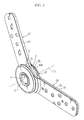
- Figure 1 is a side view of a principal portion showing a first embodiment of an angle-adjustable hinge of the present invention.
- Figure 2 is an exploded perspective view.
- Figure 3 is a perspective view of an assembled state.
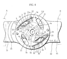
- Figure 4 is a side view of a principal portion showing a state after an oscillation.
- the angle-adjustable hinge of the present invention is, for example, used as a hinge with which inclination angle of a back portion and armrest can be adjusted.
- the hinge may be used to oscillatably connect two members such as in opening and closing doors.
- the hinge is provided with a pair of parallel wall portions 2 formed circular of which center is the first axis C 1 , the center of oscillation (pivot) of members forming the angle to be adjusted, four wedge-shaped window portions 21 disposed rotationally symmetric for every 90° around the first axis C 1 as the axis of symmetry, a pair of floating wedge members 3 disposed rotationally symmetric for 180 ° around the first axis C 1 as the axis of symmetry, a pair of gear portions 4 disposed rotationally symmetric for 180° around the first axis C 1 as the axis of symmetry, spring wires 5 elastically pushing the floating wedge members 3 to the gear portions 4, cover members 6 holding the wall portions 2 from the first axis C 1 directions, and an attachment shaft 7 to concentrically pivot the wall portions 2, the gear portions 4, and the cover members 6.
- Each of the pair of wall portions 2 is formed as a circular plate.
- the four wedge-shaped window portions 21 penetrate each of the pair of wall portions 2 on rotationally symmetric positions for every 90 ° around the first axis C 1 as the axis of symmetry.
- a contact pin portion 22 which contacts an end 5a of the spring wire 5, and an axis pin portion 23, to which another end 5b of the spring wire 5 is supported, are protruding from a position near the both ends in a peripheral direction of each of the wedge-shaped window portion 21 on an outer side faces 2a (the outer faces in the first axis C 1 ) of the wall portions 2.
- a central hole is formed concentrically with the first axis C 1 .
- the interval between the pair of wall portions 2 is set to be an interval dimension T, in which the gear portion 4 can be disposed, serves as a case portion which stores the gear portion 4.
- a plate-shaped attachment piece portion 25 protrudes from the wall portion 2 in an outer radial direction of the first axis C 1 .
- the wall portions 2 and the attached portions 25 are facing and the attached portions 25 are unitedly fixed by face contact and spot welding.
- the attached portion 25 has attachment through holes 25b for attachment of members to be oscillated.
- the unitedly fixed attached portion 25 form an attachment arm portion.
- the present invention is provided with an oscillation case member 20, in which the pair of wall portions (case portion) being able to include the gear portion 4 and the attachment piece portion (the attachment arm portion) to which the member to be oscillated is attached, by fixing two plate-shaped members having the wall portion 2 and the attachment piece portion 25. And, the contact pin portion 22 and the axis pin portion 23 are formed by press-fitting of pin members into the wall portion 2.
- an arc-shaped wedge face 21a is formed on an outer side when the side near the first axis C 1 is defined as an inner side.
- the wedge face 21a is formed serially as to have a second axis C 2 , eccentric from the first axis C 1 and rotation symmetric for every 90 ° around the first axis C 1 as the axis of symmetry, as the center, and as to come close to the gear portion 4. That is to say, the interval between the wedge face 21a and the gear portion 4 becomes gradually small (diminishes) as being formed in an arrow N 1 direction shown in Figure 1 .
- a floating staged portion 21b is formed as to protrude from an arc face 21c and guide the floating wedge member 3.
- the wedge-shaped window portion 21 has a retreat space 21d to store the floating wedge member 3 when not engaged to the gear portion 4 (unengaged state).
- the arrow N 1 direction is the same rotational direction as the peripheral direction in which the oscillation of the gear portion 4 should be restricted.
- the floating wedge members 3 are disposed to be rotation symmetric for 180 ° around the first axis C 1 as the axis of symmetry, and inserted to the wedge-shaped window portions 21 on the positions rotationally symmetric for 180° .
- the floating wedge member 3 is formed to have a second width dimension W 2 slightly larger than the first width dimension W 1 of the wall portions 2.
- the floating wedge member 3 partially (on both end sides) protrudes from the outer side faces 2a of the wall portions 2 when inserted to the wedge-shaped window portion 21.
- the floating wedge member 3 is disposed as to move within the wedge-shaped window portion 21.
- One side of the floating wedge member 3 is formed into a toothed face 31 to engage to the gear portion 4.
- Another side of the floating wedge member 3 is formed into an arc-shaped contact face 32 to contact the wedge face 21a.
- the contact face 32 is formed as to be guided by the wedge face 21a to place the floating wedge member 3 between the gear portion 4 and the wedge face 21a when the gear portion 4 oscillates and the floating wedge member 3 is moved by the engagement of the toothed face 31 to the gear portion 4.
- the floating wedge member 3 restricts the oscillation of the gear portion 4. That is to say, the floating wedge member 3 restricts the oscillation of the gear portion 4 in one direction by the engagement of the toothed face 31 to the gear portion 4 and the contact of the contact face 32 with the wedge face 21a.
- the floating wedge member 3 has a guiding slope 33 which contacts the floating staged portion 21b and guides itself in a direction parting from the gear portion 4.
- the guiding slope 33 is formed on a rear edge portion of the toothed face 31.
- Each of the pair of gear portions 4 is formed arc-shaped of which center is the first axis C 1 .
- the pair of gear portions 4 is formed as a plate having teeth on the outer side and pivoted between the pair of wall portions 2 as to oscillate around the first axis C 1 .
- the gear portions 4 are formed on positions in rotation symmetry for 180° of which axis of symmetry is the first axis C 1 .
- a plate-shaped attachment piece portion 45 protrudes from the pair of gear portions 4 in an outer radial direction of the first axis C 1 .
- the pair of gear portions are surrounded by a ring protection portion 42, formed circular of which center is the first axis C 1 , through escape window portions 43 to which the floating wedge member 3 is inserted.
- a connecting portion 44 to connect the ring protection portion 42 protrudes from the opposite side to the protrusion of the attachment piece portion 45.
- the present invention is provided with an oscillation gear member 40 of a plate in which the gear portions 4, the ring protection portion 42, the escape window portions 43, the connecting portion 44, and the attachment piece portion 45 are unitedly formed.
- This configuration hardly generates stress concentration on the base end portion 45a.
- a central through hole is formed concentrically with the first axis C 1 .
- the attachment piece portion 45 has plural attachment through holes 45b to which the member to be oscillated is attached.
- a push-out protrusion 4b for pushing out the floating wedge member 3 stored within the retreat space 21d, is formed on another end portion (a beginning side of the engagement) opposite to the end side of the gear portion 4 on which the push-in protrusion 4a is formed.
- a second radius dimension r of the ring protection portion 42 on outer periphery of which center is the first axis C 1 is set to be the same as a first radius dimension R of the pair of wall portions 2 on outer periphery of which center is the first axis C 1 .
- a thickness dimension t of the ring protection portion 42 in the first axis C 1 direction is set to be approximately same as the interval dimension T between the wall portions 2.
- First peripheral faces 2b of the wall portions 2 and second peripheral faces 44b of the ring protection portion 42 are formed to make a united face (having only slight difference and gaps within the assembly and working tolerance). Foreign matter is prevented from getting between the wall portions and the gear portion 4. The engaged portion and sliding portion of the gear portion 4 and the floating wedge member 3 are protected.
- the spring wire 5 is cut into a predetermined length and formed straight.
- the end 5a is formed straight, and the other end 5b is bent into a hook or circle as to fit to the axis pin portion 23.
- the spring wire 5 is made arc when touched by the contact face 32 of the floating wedge member 3 exposed on (protruding from) the outer faces 2a of the wall portions 2.
- the recovering force from the arc to the straight configuration is used as elastic pushing force. That is to say, the spring wire 5 is disposed as to elastically push the floating wedge member 3 toward the gear portion 4.
- two units of the spring wire 5 are provided for one floating wedge member 3 through the wall portions 2 in the first axis C 1 . Four units of the spring wire 5 are provided in all.
- Each of the cover members 6 is formed in a thin circle (disc) as to cover the outer face 2a of the wall portion 2.
- a third radius dimension L on the periphery is set to be the same as the first radius dimension R and the second radius dimension r.
- the cover members 6 are disposed as to cover the floating wedge member 3, the spring wire 5, and the gear portion 4 exposed from the wedge-shaped window portion 21 on the both sides in the first axis C 1 direction.
- the cover members 6 protect the floating wedge member 3, the spring wire 5, and the gear portion 4 exposed from the wedge-shaped window portion 21 against foreign matters.
- the exposed working portion (the gear portion 4, the floating wedge member 3, the spring wire 5) does not damage fabric and cushion of sofas.
- a through hole is concentrically formed with the first axis C 1 .
- the floating wedge member 3 engages to the gear portion 4, and the contact face 32 contacts the wedge face 21a of the wedge-shaped window portion 21 to stop the oscillation of the gear portion 4 by wedge work.
- the gear portion 4 oscillates in a direction to make the wedge face 21a and the gear portion 4 apart (in an arrow N 2 direction).
- the contact face 32 of the floating wedge member 3 is departed from the wedge face 21a to make a slight gap d.
- the gear portion 4 (the back B) slightly oscillates until the contact face 32 of the engaged floating wedge member 3 contacts the wedge face 21a in an arrow N 3 direction opposite to the arrow N 2 direction. After the slight oscillation in the arrow N 3 direction, the oscillation of the gear portion 4 (the back B) is restricted by the wedge work. The back B is held with the desired reclining (inclination) angle to the seat A.
- the push-in protrusion 4a of the gear portion 4 contacts the floating wedge member 3, and the floating wedge member 3 presses the gear portion 4 when the gear portion 4 (the back B) is oscillated for a predetermined amount (to the end portion of the gear portion 4).
- the guiding slope 33 slides on the floating staged portion 21b, the floating wedge member 3 is guided (lead) to and stored in the retreat space 21d formed on the rear end of the wedge-shaped window portion 21 as shown in Figure 1 and Figure 5E .
- the oscillation of the gear portion 4 in the arrow N 2 direction is restricted.
- the gear portion 4 becomes able to freely oscillate in the arrow N 2 direction when the floating wedge member 3 is stored in the retreat space 21d and the engagement is released.
- the push-out protrusion 4b of the gear portion 4 contacts the floating wedge member 3, and the floating wedge member 3 is pushed out of the retreat space 21d when the gear portion 4 (the back B) is oscillated for a predetermined amount (to the beginning portion of the gear portion 4) in the arrow N 3 direction.
- the floating wedge member 3 engages to the gear portion 4 and restricts the oscillation of the gear portion 4 (the back B) in the arrow N 3 direction by wedge work.
- the state of Figure 5A is made again, the oscillation of the gear portion 4 (the back B) in the arrow N 3 direction is made possible, and the back B can be maintained (held) on a desired position. That is to say, the floating wedge member 3 restricts the oscillation of the gear portion 4 in one direction (the arrow N 3 direction) by the engagement of the toothed face 31 to the gear and the contact of the contact face 32 with the wedge face 21a.
- the pair of floating wedge members 3 hold the pair of gear portions 4. If the gear portions 4 are made oscillate by the load, one of the floating wedge members 3 escapes in a direction to release the engagement to one of the gear portions 4. The escaping force will let the other floating wedge member 3, on the position of rotation symmetry for 180° , bite to the gear portion 4 through the wall portion 2. The floating wedge member 3 is not departed from the gear portion 4 by the load, and the engagement state is always kept when the load is supported. And, equal load (pressure) is generated on the position of rotation symmetry for 180° and extreme stress concentration on the wedge-shaped window portions 21, the floating wedge members 3, and the gear portions 4 is prevented. The wedge-shaped window portions 21, the floating wedge members 3, and the gear portions 4 are made small and thin.
- each of the floating wedge members 3, and each of the gear portions 4 smoothly contacts and parts from. If the gear portion 4 escapes as to depart from one of the floating wedge members 3, the escape is restricted by the other of the floating wedge members 3 on the position of rotation symmetry for 180 ° .
- the ring protection portion 42 protects members within the wall portions 2. Rags of cushion member of the sofa and dust are prevented from intruding to the gear portions 4, the engagement portion of the gear portions 4 and the floating wedge members 3, and the contact and sliding portions of the floating wedge members 3 and the wedge-shaped window portions 21.
- the toothed face 31 is engaged to the gear portion 4 by the outer side face 2a as a guiding face without dislocation when the floating wedge member 3 is elastically pushed on the both sides because the spring wire 5 is disposed on both of the outer side faces 2a of the wall portions 2.
- the interval dimension T can be set smaller because the spring wire 5 is disposed on the outer side of the wall portions 2.
- the oscillation case member 20 and the oscillation gear member 40 can be made thin.
- the floating wedge members 3 restrict the oscillation from the bent state to the straight state.
- the floating wedge members 3 are moved to the wedge-shaped window portions 21 where the floating wedge members 3 are not inserted in Figure 1 and Figure 4 (when each of the floating wedge members 3 is respectively inserted to each of the wedge-shaped window portions 21 disposed on the positions of rotation symmetry for 90 ° of which axis of symmetry is the first axis C 1 )
- the oscillation from the straight state to the bent (inclined) state is restricted, and switched to adjustable state for the oscillation (reclining) angle.
- the reclining angle of the armrest portion C becomes adjustable from the state of Figure 6A , where the side wall portion D is upright and the armrest portion C is horizontal, to the state of Figure 6B where the armrest portion C is rising.
- the armrest portion C (the oscillation gear member 40) receives load from a person sitting on the sofa and leaning toward an outer direction of the sofa, the oscillation of the armrest portion C (the gear portion 4) is restricted by the floating wedge member 3.
- the direction of restriction and starting posture of the angle adjustment are switched by selection of two wedge-shaped window portions 21 on the positions in rotation symmetry for 180 ° among the four wedge-shaped window portions 21 on the positions in rotation symmetry for every 90 ° to insert (transfer) the floating wedge members 3.
- the switching is conducted between the state shown in Figure 1 and Figure 4 , where the starting posture for angle adjustment is straight and the reclining (oscillation) angle can be set until the hinge is folded to be L-shaped, and the state shown in Figure 6A where the starting posture is inverted L-shaped and the reclining angle can be set until the hinge is made straight.
- the transfer of the floating wedge members 3 can correspond to various oscillating portions such as backs of sofas, armrests, headrests, etc.
- the embodiment is provided with a pair of wall portions 2, a pair of gear portions 4, and a pair of floating wedge members 3, and two wedge-shaped window portions 21 are disposed on each of the wall portions 2 on positions in rotation symmetry for 180° of which axis of symmetry is first axis C 1 .
- the floating wedge members 3 are respectively inserted to the wedge-shaped window portions 21.
- the wedge face 21a of the wedge-shaped window portion 21 is formed arc-shaped as to serially have the second axis C 2 , eccentric from the first axis C 1 and rotation symmetric for every 180 ° around the first axis C 1 as the axis of symmetry.
- force (load) working on the gear portion 4 and the floating wedge member 3 is supported by the pair of gear portions 4 and the pair of floating wedge members 3 disposed on the positions in rotation symmetry for 180° .
- Pressure is reduced by letting the floating wedge members 3 contact the gear portion 4 as to hold and restrict the oscillation with good balance.
- Each of the floating wedge members 3 contacts and departs from each of the gear portions 4 to adjust the oscillation angle.
- the oscillation case member 20 may be formed by bending one plate member, and screw holes may be formed on the attachment piece portion 25 and the attachment piece portion 45.
- the force (load) working on the gear portion 4 and the floating wedge member 3 is uniformly dispersed and reduced, because the pair of arc-shaped gear portions 4 oscillatable around the first axis C 1 and formed outward from the first axis C 1 as the center, four wedge-shaped window portions 21 disposed on positions in rotation symmetry for every 90 ° of which axis of symmetry is the first axis C 1 , and the pair of floating wedge members 3, disposed movably within the wedge-shaped window portions 21, of which one face side is the toothed face 31 to engage with the gear portion 4 and another face side is the contact face 32 to contact the wedge face 21a on the outer side of the wedge-shaped window portion 21 to restrict the gear portion 4 to oscillate in a direction, are provided, the pair of floating wedge members 3 are disposed on positions in rotation symmetry for 180 ° of which axis of symmetry is the first axis C 1 , and the wedge faces 21a of the four wedge-shaped window portions 21 are formed serially on
- the gear portion 4 and the floating wedge member 3 and the entire angle-adjustable hinge can be small and thin.
- the floating wedge members 3 contact and hold the gear portions 4 to restrict the oscillation with good balance.
- the load is uniformly working and certainly supported.
- Durability of the hinge is improved.
- the direction of the oscillation to be restricted is switchable.
- the starting posture, in which the angle can be adjusted, can be switched for 90° .
- the hinge can correspond to various oscillation portions.
- the force (load) working on the gear portion 4 and the floating wedge member 3 is uniformly dispersed and reduced, because the pair of arc-shaped gear portions 4 oscillatable around the first axis C 1 and formed outward from the first axis C 1 as the center, two wedge-shaped window portions 21 disposed on positions in rotation symmetry for 180 ° of which axis of symmetry is the first axis C 1 , and the pair of floating wedge members 3, disposed movably within the wedge-shaped window portions 21, of which one face side is the toothed face 31 to engage with the gear portion 4 and another face side is the contact face 32 to contact the wedge face 21a on the outer side of the wedge-shaped window portion 21 to restrict the gear portion 4 to oscillate in a direction, are provided, the pair of floating wedge members 3 are disposed on positions in rotation symmetry for 180 ° of which axis of symmetry is the first axis C 1 , and the wedge faces 21a of the two wedge-shaped window portions 21 are formed serially on arcs each of which center is the
- the gear portion 4 and the floating wedge member 3 and the entire angle-adjustable hinge can be small and thin.
- the floating wedge members 3 contact and hold the gear portions 4 to restrict the oscillation with good balance.
- the load is uniformly working and certainly supported. Durability of the hinge is improved.
- the force (load) working on the gear portion 4 and the floating wedge member 3 is uniformly dispersed and reduced, because the pair of parallel and plate-shaped wall portions 2, the pair of arc-shaped gear portions 4 disposed between the wall portions 2 and oscillatable around the first axis C 1 and formed outward from the first axis C 1 as a center, four wedge-shaped window portions 21 disposed on each of the wall portions 2 on positions in rotation symmetry for every 90° of which axis of symmetry is the first axis C 1 , and the pair of floating wedge members 3, disposed movably within the wedge-shaped window portions 21, of which one face side is the toothed face 31 to engage with the gear portion 4 and another face side is the contact face 32 to contact the wedge face 21a on the outer side of the wedge-shaped window portion 21 to restrict the gear portion 4 to oscillate in a direction, are provided, the pair of floating wedge members 3 are disposed on positions in rotation symmetry for 180 ° of which axis of symmetry is the first axis C 1 , and the
- the gear portion 4 and the floating wedge member 3 and the entire angle-adjustable hinge can be small and thin.
- the floating wedge members 3 contact and hold the gear portions 4 to restrict the oscillation with good balance.
- the load is uniformly working and certainly supported.
- Durability of the hinge is improved.
- the direction of the oscillation to be restricted is switchable.
- the starting posture, in which the angle can be adjusted, can be switched for 90 ° .
- the hinge can correspond to various oscillation portion.
- the force (load) working on the gear portion 4 and the floating wedge member 3 is uniformly dispersed and reduced, because the pair of parallel and plate-shaped wall portions 2, the pair of arc-shaped gear portions 4 disposed between the wall portions 2 and oscillatable around the first axis C 1 and formed outward from the first axis C 1 as a center, two wedge-shaped window portions 21 disposed on each of the wall portions 2 on positions in rotation symmetry for 180° of which axis of symmetry is the first axis C 1 , and the pair of floating wedge members 3, disposed movably within the wedge-shaped window portions 21, of which one face side is the toothed face 31 to engage with the gear portion 4 and another face side is the contact face 32 to contact the wedge face 21a on the outer side of the wedge-shaped window portion 21 to restrict the gear portion 4 to oscillate in a direction, are provided, the pair of floating wedge members 3 are disposed on positions in rotation symmetry for 180 ° of which axis of symmetry is the first axis C 1 , and the wedge
- the gear portion 4 and the floating wedge member 3 and the entire angle-adjustable hinge can be small and thin.
- the floating wedge members 3 contact and hold the gear portions 4 to restrict the oscillation with good balance.
- the load is uniformly working and certainly supported. Durability of the hinge is improved.
- the gear portion 4 and the base end portion 45a of the attachment piece portion 45 can be improved, because the oscillation gear member 40, in which the pair of gear portions 4, the attachment piece portion 45 protruding from the pair of gear portions 4, the ring protection portion 42, of which center is the first axis C 1 , circularly surrounding the pair of gear portions 4 through the escape window portions 43 to which the floating wedge members 3 are inserted, and the connecting portion 44 protruding from the opposite side to the attachment piece portion 45 and connecting the pair of gear portions 4 and the ring protection portion 42, are unitedly formed, is provided. And, durability can be improved.
- the gear portion 4 can be protected.
- the hinge can be made easily and economically by press-working. THe hinge can be attached to small limited spaces such as inside a sofa.
- the floating wedge member 3 can be engaged to the gear portion 4 without dislocation, because the contact pin portion 22, which one end 5a of the spring wire 5 formed straight of a predetermined length contacts, and the axis pin portion 23, on which another end 5b of the spring wire 5 is supported, protrude from the outer side face 2a of the wall portion 2 and near both ends of each of the wedge-shaped window portions 21 in peripheral direction, and, the spring wire 5 contacts and elastically pushes the floating wedge member 3, exposed of the wedge-shaped window portion 21, as to be pressed to the gear portion 4.
- the interval dimension T can be set small for the spring wire 5 not disposed within the pair of wall portions 2, and the thickness dimension t of te gear portion 4 can be thin.
- the spring wire 5 can be attached only with slight protrusions of the contact pin portion 22 and the axis pin portion 23. That is to say, the entire angle-adjustable hinge can be made thin. And, the spring wire 5 can be made easily and economically.
Landscapes
- Engineering & Computer Science (AREA)
- Aviation & Aerospace Engineering (AREA)
- Transportation (AREA)
- Mechanical Engineering (AREA)
- Health & Medical Sciences (AREA)
- Dentistry (AREA)
- General Health & Medical Sciences (AREA)
- Chairs For Special Purposes, Such As Reclining Chairs (AREA)
- Pivots And Pivotal Connections (AREA)
Applications Claiming Priority (1)
| Application Number | Priority Date | Filing Date | Title |
|---|---|---|---|
| JP2008135829A JP4296223B1 (ja) | 2008-05-23 | 2008-05-23 | 角度調整金具 |
Publications (2)
| Publication Number | Publication Date |
|---|---|
| EP2123194A1 true EP2123194A1 (de) | 2009-11-25 |
| EP2123194B1 EP2123194B1 (de) | 2010-11-17 |
Family
ID=40791635
Family Applications (1)
| Application Number | Title | Priority Date | Filing Date |
|---|---|---|---|
| EP08021369A Active EP2123194B1 (de) | 2008-05-23 | 2008-12-09 | Winkelverstellbares Scharnier |
Country Status (5)
| Country | Link |
|---|---|
| US (1) | US8104141B2 (de) |
| EP (1) | EP2123194B1 (de) |
| JP (1) | JP4296223B1 (de) |
| CN (1) | CN101584536B (de) |
| DE (1) | DE602008003532D1 (de) |
Cited By (7)
| Publication number | Priority date | Publication date | Assignee | Title |
|---|---|---|---|---|
| EP2617323A1 (de) * | 2012-01-19 | 2013-07-24 | Hettich Franke GmbH & Co. KG | Schwenkbeschlag für ein Möbel, insbesondere ein Polstermöbel |
| EP2708411A1 (de) * | 2012-09-14 | 2014-03-19 | Grammer Ag | Sitz, insbesondere Fahrzeugsitz, mit Schwenkachse |
| EP2708406A1 (de) * | 2012-09-14 | 2014-03-19 | Grammer Ag | Sitz mit einer Arretierungseinrichtung |
| EP2708412A1 (de) * | 2012-09-14 | 2014-03-19 | Grammer Ag | Sitz mit am Boden abgestützter Rückenlehne |
| WO2014180764A1 (de) * | 2013-05-07 | 2014-11-13 | Ferdinand Lusch Gmbh & Co. Kg | Schwenkbeschlag für sitz- und/oder liegemöbel |
| DE102017100697A1 (de) * | 2016-12-16 | 2018-06-21 | F.S. Fehrer Automotive Gmbh | Rücksitzlehnenelement |
| EP3569105A1 (de) * | 2018-05-14 | 2019-11-20 | Ferdinand Lusch Gmbh & Co. Kg. | Schwenkgelenk zum verstellen eines funktionsteils eines möbels |
Families Citing this family (45)
| Publication number | Priority date | Publication date | Assignee | Title |
|---|---|---|---|---|
| KR100911572B1 (ko) * | 2007-10-18 | 2009-08-10 | 현대자동차주식회사 | 테일게이트 글래스의 힌지장치 |
| JP4418519B1 (ja) * | 2009-05-22 | 2010-02-17 | 直伸 山下 | 角度調整金具 |
| JP2011020616A (ja) * | 2009-07-17 | 2011-02-03 | Suzuki Motor Corp | ウィンドスクリーン装置 |
| CN101633332B (zh) * | 2009-08-19 | 2014-07-30 | 浙江天成自控股份有限公司 | 车辆座椅靠背安全保护锁止机构 |
| JP4624479B1 (ja) | 2010-05-26 | 2011-02-02 | 直伸 山下 | 角度調整金具 |
| CN201718842U (zh) * | 2010-06-30 | 2011-01-26 | 梁华春 | 二挡合页 |
| CN201814188U (zh) * | 2010-06-30 | 2011-05-04 | 梁华春 | 三挡焊接合页 |
| JP5498327B2 (ja) * | 2010-09-13 | 2014-05-21 | 直伸 山下 | 角度調整金具及び角度調整金具セット |
| US9145072B2 (en) * | 2010-11-24 | 2015-09-29 | Everett Sollars | Power disc style seat recliner |
| US8550559B2 (en) * | 2010-11-24 | 2013-10-08 | Everett Sollars | Power disc style seat recliner |
| JP4831713B1 (ja) | 2011-04-25 | 2011-12-07 | 直伸 山下 | 角度調整金具 |
| CN103185192A (zh) * | 2011-12-28 | 2013-07-03 | 富泰华工业(深圳)有限公司 | 折叠型支架 |
| PL2803296T3 (pl) * | 2012-01-11 | 2017-09-29 | Wei Lu | Regulator zawiasu |
| DE102012013208B4 (de) | 2012-05-07 | 2019-07-25 | Adient Luxembourg Holding S.À R.L. | Sitzteil eines Fahrzeugsitzes |
| IN2014DN08535A (de) | 2012-05-07 | 2015-05-15 | Johnson Controls Tech Co | |
| US9199658B2 (en) * | 2012-06-22 | 2015-12-01 | Khai Gan Chuah | Baby stroller folding mechanism |
| JP2014004049A (ja) * | 2012-06-22 | 2014-01-16 | Naonobu Yamashita | 揺動金具の取付ソケット |
| ITMI20120390U1 (it) * | 2012-10-31 | 2014-05-01 | Motion S R L | Dispositivo di movimentazione a cricchetto |
| CN102989146B (zh) * | 2012-12-18 | 2015-07-15 | 黄虎生 | 可折叠框架 |
| US8875347B2 (en) * | 2012-12-21 | 2014-11-04 | Taco Metals; Inc. | Hinge employing a ratchet for an upholstery seat |
| US9249827B2 (en) * | 2012-12-21 | 2016-02-02 | Taco Metals, Inc. | Hinge employing a ratchet for an upholstery seat |
| JP5555341B1 (ja) * | 2013-02-15 | 2014-07-23 | 直伸 山下 | 角度調整金具及び座椅子 |
| JP5611416B1 (ja) * | 2013-05-20 | 2014-10-22 | 山下 直伸 | 角度調整金具 |
| JP5498608B1 (ja) * | 2013-05-20 | 2014-05-21 | 直伸 山下 | ソファー |
| CN103671474B (zh) * | 2013-12-13 | 2015-10-28 | 江苏大学 | 一种带有旋钮开关的角度调节器 |
| US9315205B2 (en) * | 2014-09-18 | 2016-04-19 | Khai Gan Chuah | Folding mechanism of baby stroller |
| CN104887451A (zh) * | 2015-06-25 | 2015-09-09 | 安徽久工健业股份有限公司 | 按摩椅扶手 |
| US9399421B2 (en) * | 2015-10-19 | 2016-07-26 | Dongguan Weihong Hardware And Plastic Products Co., Ltd. | Hinge |
| US10138664B2 (en) | 2016-03-21 | 2018-11-27 | Taylor Made Group, Llc | Hinge with adjustable axis location and locking mechanism |
| SE541067C2 (en) * | 2016-06-03 | 2019-03-26 | Husqvarna Ab | Floor grinding machine and method of setting a handle for a floor grinding machine |
| JP2018000381A (ja) | 2016-06-29 | 2018-01-11 | 向陽技研株式会社 | 角度調整金具およびこれを用いたソファー |
| CN106523516B (zh) * | 2016-11-14 | 2019-01-15 | 苏州三星电子电脑有限公司 | 自锁转轴与具有该自锁转轴的笔记本电脑 |
| US10337223B2 (en) * | 2016-11-23 | 2019-07-02 | Kohler Co. | Shower door hinge assembly |
| JP2018179289A (ja) * | 2017-04-20 | 2018-11-15 | 山下 直伸 | 角度調整具 |
| DE102017110246A1 (de) * | 2017-05-11 | 2018-11-15 | Hettich Franke Gmbh & Co. Kg | Schwenkbeschlag und Möbel |
| DE102017110253A1 (de) * | 2017-05-11 | 2018-11-15 | Hettich Franke Gmbh & Co. Kg | Schwenkbeschlag und Möbel |
| JP6404400B1 (ja) * | 2017-05-11 | 2018-10-10 | 向陽技研株式会社 | 角度調整金具およびこれを用いた家具 |
| DE102017110249A1 (de) * | 2017-05-11 | 2018-11-15 | Hettich Franke Gmbh & Co. Kg | Schwenkbeschlag und Möbel |
| FR3066241B1 (fr) * | 2017-05-12 | 2019-07-26 | Tournadre Sa Standard Gum | Dispositif d'articulation ameliore pour meuble de couchage ou d'assise |
| US20190255979A1 (en) * | 2018-02-22 | 2019-08-22 | Lear Corporation | Recliner retention ring and method of making the same |
| US11371804B2 (en) * | 2018-11-02 | 2022-06-28 | Edge-Works Manufacturing Company | Adjustable fastening system |
| US10765584B2 (en) * | 2019-01-03 | 2020-09-08 | Shanq-Ching Shieh | Foldable frame construction for mobility aids |
| DE102019119307A1 (de) * | 2019-07-16 | 2021-01-21 | Hettich Franke Gmbh & Co. Kg | Möbel und Verfahren zur Montage eines Möbels |
| CN210902243U (zh) * | 2019-09-09 | 2020-07-03 | 东莞市伟宏智能家居科技有限公司 | 头枕角度调节器 |
| US11918500B1 (en) | 2020-03-31 | 2024-03-05 | Preferred Prescription, Inc. | Hinged knee brace with double upper strap arrangement |
Citations (3)
| Publication number | Priority date | Publication date | Assignee | Title |
|---|---|---|---|---|
| JPS5920118Y2 (ja) | 1981-02-05 | 1984-06-11 | 善伸 山下 | 座椅子用ラチエット金具 |
| DE10009038A1 (de) * | 1999-02-25 | 2000-09-07 | Faure Bertrand Equipements Sa | Gelenkmechanismus für Fahrzeugsitz und mit einem solchen Mechanismus ausgestatteter Sitz |
| DE20112976U1 (de) * | 2001-08-13 | 2001-10-18 | Franke Gmbh & Co Kg | Schwenkbeschlag |
Family Cites Families (19)
| Publication number | Priority date | Publication date | Assignee | Title |
|---|---|---|---|---|
| US3586355A (en) * | 1969-01-13 | 1971-06-22 | Dominion Auto Access | Hinge joint assemblies |
| JPS5247180B2 (de) * | 1972-06-07 | 1977-11-30 | ||
| DE2328908C3 (de) * | 1973-06-06 | 1980-05-14 | Metallwerk Max Brose Gmbh & Co, 8630 Coburg | Gelenkbeschlag für Sitze, insbesondere Kraftfahrzeugsitze |
| US3961497A (en) * | 1975-07-28 | 1976-06-08 | Sphero International Company | Universal joint |
| US4082352A (en) * | 1977-01-13 | 1978-04-04 | Lear Siegler, Inc. | Seat back recliner |
| US4087885A (en) * | 1977-07-05 | 1978-05-09 | Rockwell International Corporation | Adjustable hinge |
| US4890950A (en) * | 1988-11-08 | 1990-01-02 | Yoo Hoe G | Positioning joint for a folding ladder |
| JP2631760B2 (ja) * | 1990-06-28 | 1997-07-16 | 星野楽器株式会社 | 角度調節機構 |
| KR100269846B1 (ko) * | 1997-10-02 | 2000-10-16 | 김영조 | 도어클로즈용 도어의 걸림장치 |
| JP3436501B2 (ja) * | 1999-02-03 | 2003-08-11 | 向陽技研株式会社 | 角度調整具 |
| JP4374657B2 (ja) * | 1999-06-08 | 2009-12-02 | アイシン精機株式会社 | シートリクライニング装置 |
| US6993808B1 (en) * | 2000-09-18 | 2006-02-07 | Lenjoy Medical Engineering, Inc. | Adjustable hinges for orthopedic splints |
| US6711780B2 (en) * | 2001-08-22 | 2004-03-30 | Sinclair Worldwide, Inc. | Hinge for collapsible ladders |
| DE10338413A1 (de) * | 2002-08-19 | 2005-03-24 | Grammer Ag | Armlehne |
| JP3766669B2 (ja) * | 2003-08-29 | 2006-04-12 | 直伸 山下 | 角度調整金具 |
| US7093321B2 (en) * | 2004-06-07 | 2006-08-22 | Cosco Management, Inc. | Lockable hinge |
| JP2006207756A (ja) * | 2005-01-31 | 2006-08-10 | Kokuyo Co Ltd | ラチェット機構、椅子 |
| JP4418382B2 (ja) * | 2005-02-25 | 2010-02-17 | 直伸 山下 | 角度調整金具 |
| JP4778733B2 (ja) * | 2005-06-09 | 2011-09-21 | 富士機工株式会社 | 車両用シートリクライニング装置 |
-
2008
- 2008-05-23 JP JP2008135829A patent/JP4296223B1/ja active Active
- 2008-12-09 DE DE602008003532T patent/DE602008003532D1/de active Active
- 2008-12-09 US US12/330,990 patent/US8104141B2/en not_active Expired - Fee Related
- 2008-12-09 EP EP08021369A patent/EP2123194B1/de active Active
- 2008-12-22 CN CN200810190863.4A patent/CN101584536B/zh active Active
Patent Citations (3)
| Publication number | Priority date | Publication date | Assignee | Title |
|---|---|---|---|---|
| JPS5920118Y2 (ja) | 1981-02-05 | 1984-06-11 | 善伸 山下 | 座椅子用ラチエット金具 |
| DE10009038A1 (de) * | 1999-02-25 | 2000-09-07 | Faure Bertrand Equipements Sa | Gelenkmechanismus für Fahrzeugsitz und mit einem solchen Mechanismus ausgestatteter Sitz |
| DE20112976U1 (de) * | 2001-08-13 | 2001-10-18 | Franke Gmbh & Co Kg | Schwenkbeschlag |
Cited By (9)
| Publication number | Priority date | Publication date | Assignee | Title |
|---|---|---|---|---|
| EP2617323A1 (de) * | 2012-01-19 | 2013-07-24 | Hettich Franke GmbH & Co. KG | Schwenkbeschlag für ein Möbel, insbesondere ein Polstermöbel |
| EP2708411A1 (de) * | 2012-09-14 | 2014-03-19 | Grammer Ag | Sitz, insbesondere Fahrzeugsitz, mit Schwenkachse |
| EP2708406A1 (de) * | 2012-09-14 | 2014-03-19 | Grammer Ag | Sitz mit einer Arretierungseinrichtung |
| EP2708412A1 (de) * | 2012-09-14 | 2014-03-19 | Grammer Ag | Sitz mit am Boden abgestützter Rückenlehne |
| WO2014180764A1 (de) * | 2013-05-07 | 2014-11-13 | Ferdinand Lusch Gmbh & Co. Kg | Schwenkbeschlag für sitz- und/oder liegemöbel |
| US9683397B2 (en) | 2013-05-07 | 2017-06-20 | Ferdinand Lusch Gmbh & Co. Kg | Pivot fitting for pieces of furniture for sitting and/or lying on |
| DE102017100697A1 (de) * | 2016-12-16 | 2018-06-21 | F.S. Fehrer Automotive Gmbh | Rücksitzlehnenelement |
| DE102017100697B4 (de) | 2016-12-16 | 2021-09-16 | F.S. Fehrer Automotive Gmbh | Rücksitzlehnenelement |
| EP3569105A1 (de) * | 2018-05-14 | 2019-11-20 | Ferdinand Lusch Gmbh & Co. Kg. | Schwenkgelenk zum verstellen eines funktionsteils eines möbels |
Also Published As
| Publication number | Publication date |
|---|---|
| US20090288270A1 (en) | 2009-11-26 |
| CN101584536A (zh) | 2009-11-25 |
| CN101584536B (zh) | 2014-05-14 |
| JP4296223B1 (ja) | 2009-07-15 |
| EP2123194B1 (de) | 2010-11-17 |
| DE602008003532D1 (de) | 2010-12-30 |
| JP2009279262A (ja) | 2009-12-03 |
| US8104141B2 (en) | 2012-01-31 |
Similar Documents
| Publication | Publication Date | Title |
|---|---|---|
| EP2123194B1 (de) | Winkelverstellbares Scharnier | |
| CN110612047B (zh) | 枢转配件和家具 | |
| EP2767188B1 (de) | Winkeleinstellbares Scharnier und Sofa | |
| EP2389839B1 (de) | Scharnier mit einstellbarer Winkel | |
| WO2011155557A1 (ja) | 椅子 | |
| EP2532275B1 (de) | Scharnier mit einstellbarem Winkel | |
| KR101593116B1 (ko) | 의자 등받이 틸팅장치 | |
| JP2011161123A (ja) | 椅子 | |
| KR20190135813A (ko) | 의자용 등받이 회전장치 | |
| US7052089B2 (en) | Multi-position headrest and mechanism therefor | |
| KR100633346B1 (ko) | 의자의 등판 설치구조 | |
| KR200469537Y1 (ko) | 의자 등받이에 있어서, 요추 받침장치 | |
| KR200436739Y1 (ko) | 헤드레스트 | |
| JP2011201526A (ja) | ヘッドレスト付車両用シート | |
| CN212815352U (zh) | 靠背椅调节结构 | |
| KR102078745B1 (ko) | 등받이용 좌우 틸트 모듈 | |
| JP6777281B2 (ja) | 椅子 | |
| KR200426287Y1 (ko) | 의자용 헤드레스트 | |
| JP7121600B2 (ja) | 椅子 | |
| JP5650491B2 (ja) | 椅子 | |
| JP5571353B2 (ja) | 椅子 | |
| KR101722316B1 (ko) | 등받이 이동 의자 | |
| KR100515954B1 (ko) | 의자 | |
| JP2017192775A (ja) | 椅子の背支持構成要素およびこれを備える椅子 | |
| KR20190011032A (ko) | 리클라이닝 체어 |
Legal Events
| Date | Code | Title | Description |
|---|---|---|---|
| PUAI | Public reference made under article 153(3) epc to a published international application that has entered the european phase |
Free format text: ORIGINAL CODE: 0009012 |
|
| AK | Designated contracting states |
Kind code of ref document: A1 Designated state(s): AT BE BG CH CY CZ DE DK EE ES FI FR GB GR HR HU IE IS IT LI LT LU LV MC MT NL NO PL PT RO SE SI SK TR |
|
| AX | Request for extension of the european patent |
Extension state: AL BA MK RS |
|
| 17P | Request for examination filed |
Effective date: 20100108 |
|
| 17Q | First examination report despatched |
Effective date: 20100205 |
|
| GRAP | Despatch of communication of intention to grant a patent |
Free format text: ORIGINAL CODE: EPIDOSNIGR1 |
|
| AKX | Designation fees paid |
Designated state(s): DE IT |
|
| GRAS | Grant fee paid |
Free format text: ORIGINAL CODE: EPIDOSNIGR3 |
|
| GRAA | (expected) grant |
Free format text: ORIGINAL CODE: 0009210 |
|
| AK | Designated contracting states |
Kind code of ref document: B1 Designated state(s): DE IT |
|
| REF | Corresponds to: |
Ref document number: 602008003532 Country of ref document: DE Date of ref document: 20101230 Kind code of ref document: P |
|
| PLBE | No opposition filed within time limit |
Free format text: ORIGINAL CODE: 0009261 |
|
| STAA | Information on the status of an ep patent application or granted ep patent |
Free format text: STATUS: NO OPPOSITION FILED WITHIN TIME LIMIT |
|
| 26N | No opposition filed |
Effective date: 20110818 |
|
| REG | Reference to a national code |
Ref country code: DE Ref legal event code: R097 Ref document number: 602008003532 Country of ref document: DE Effective date: 20110818 |
|
| PGFP | Annual fee paid to national office [announced via postgrant information from national office to epo] |
Ref country code: IT Payment date: 20231221 Year of fee payment: 16 Ref country code: DE Payment date: 20231206 Year of fee payment: 16 |