EP2115356B1 - Anlage zum trocknen von organischen massen - Google Patents
Anlage zum trocknen von organischen massen Download PDFInfo
- Publication number
- EP2115356B1 EP2115356B1 EP08707144.5A EP08707144A EP2115356B1 EP 2115356 B1 EP2115356 B1 EP 2115356B1 EP 08707144 A EP08707144 A EP 08707144A EP 2115356 B1 EP2115356 B1 EP 2115356B1
- Authority
- EP
- European Patent Office
- Prior art keywords
- mixing
- mixer
- mixing blade
- installation according
- heating device
- Prior art date
- Legal status (The legal status is an assumption and is not a legal conclusion. Google has not performed a legal analysis and makes no representation as to the accuracy of the status listed.)
- Active
Links
Images

Classifications
-
- F—MECHANICAL ENGINEERING; LIGHTING; HEATING; WEAPONS; BLASTING
- F23—COMBUSTION APPARATUS; COMBUSTION PROCESSES
- F23G—CREMATION FURNACES; CONSUMING WASTE PRODUCTS BY COMBUSTION
- F23G5/00—Incineration of waste; Incinerator constructions; Details, accessories or control therefor
- F23G5/02—Incineration of waste; Incinerator constructions; Details, accessories or control therefor with pretreatment
- F23G5/04—Incineration of waste; Incinerator constructions; Details, accessories or control therefor with pretreatment drying
-
- B—PERFORMING OPERATIONS; TRANSPORTING
- B01—PHYSICAL OR CHEMICAL PROCESSES OR APPARATUS IN GENERAL
- B01F—MIXING, e.g. DISSOLVING, EMULSIFYING OR DISPERSING
- B01F27/00—Mixers with rotary stirring devices in fixed receptacles; Kneaders
- B01F27/05—Stirrers
- B01F27/11—Stirrers characterised by the configuration of the stirrers
- B01F27/114—Helically shaped stirrers, i.e. stirrers comprising a helically shaped band or helically shaped band sections
- B01F27/1142—Helically shaped stirrers, i.e. stirrers comprising a helically shaped band or helically shaped band sections of the corkscrew type
-
- B—PERFORMING OPERATIONS; TRANSPORTING
- B01—PHYSICAL OR CHEMICAL PROCESSES OR APPARATUS IN GENERAL
- B01F—MIXING, e.g. DISSOLVING, EMULSIFYING OR DISPERSING
- B01F27/00—Mixers with rotary stirring devices in fixed receptacles; Kneaders
- B01F27/60—Mixers with rotary stirring devices in fixed receptacles; Kneaders with stirrers rotating about a horizontal or inclined axis
- B01F27/72—Mixers with rotary stirring devices in fixed receptacles; Kneaders with stirrers rotating about a horizontal or inclined axis with helices or sections of helices
- B01F27/726—Mixers with rotary stirring devices in fixed receptacles; Kneaders with stirrers rotating about a horizontal or inclined axis with helices or sections of helices with two helices with opposite pitch on the same shaft; with two helices on the same axis, driven in opposite directions or at different speeds
-
- B—PERFORMING OPERATIONS; TRANSPORTING
- B01—PHYSICAL OR CHEMICAL PROCESSES OR APPARATUS IN GENERAL
- B01F—MIXING, e.g. DISSOLVING, EMULSIFYING OR DISPERSING
- B01F33/00—Other mixers; Mixing plants; Combinations of mixers
- B01F33/70—Mixers specially adapted for working at sub- or super-atmospheric pressure, e.g. combined with de-foaming
-
- B—PERFORMING OPERATIONS; TRANSPORTING
- B01—PHYSICAL OR CHEMICAL PROCESSES OR APPARATUS IN GENERAL
- B01F—MIXING, e.g. DISSOLVING, EMULSIFYING OR DISPERSING
- B01F35/00—Accessories for mixers; Auxiliary operations or auxiliary devices; Parts or details of general application
- B01F35/45—Closures or doors specially adapted for mixing receptacles; Operating mechanisms therefor
- B01F35/451—Closures or doors specially adapted for mixing receptacles; Operating mechanisms therefor by rotating them about an axis parallel to the plane of the opening
-
- C—CHEMISTRY; METALLURGY
- C10—PETROLEUM, GAS OR COKE INDUSTRIES; TECHNICAL GASES CONTAINING CARBON MONOXIDE; FUELS; LUBRICANTS; PEAT
- C10L—FUELS NOT OTHERWISE PROVIDED FOR; NATURAL GAS; SYNTHETIC NATURAL GAS OBTAINED BY PROCESSES NOT COVERED BY SUBCLASSES C10G OR C10K; LIQUIFIED PETROLEUM GAS; USE OF ADDITIVES TO FUELS OR FIRES; FIRE-LIGHTERS
- C10L5/00—Solid fuels
- C10L5/40—Solid fuels essentially based on materials of non-mineral origin
- C10L5/44—Solid fuels essentially based on materials of non-mineral origin on vegetable substances
-
- C—CHEMISTRY; METALLURGY
- C10—PETROLEUM, GAS OR COKE INDUSTRIES; TECHNICAL GASES CONTAINING CARBON MONOXIDE; FUELS; LUBRICANTS; PEAT
- C10L—FUELS NOT OTHERWISE PROVIDED FOR; NATURAL GAS; SYNTHETIC NATURAL GAS OBTAINED BY PROCESSES NOT COVERED BY SUBCLASSES C10G OR C10K; LIQUIFIED PETROLEUM GAS; USE OF ADDITIVES TO FUELS OR FIRES; FIRE-LIGHTERS
- C10L5/00—Solid fuels
- C10L5/40—Solid fuels essentially based on materials of non-mineral origin
- C10L5/46—Solid fuels essentially based on materials of non-mineral origin on sewage, house, or town refuse
-
- F—MECHANICAL ENGINEERING; LIGHTING; HEATING; WEAPONS; BLASTING
- F26—DRYING
- F26B—DRYING SOLID MATERIALS OR OBJECTS BY REMOVING LIQUID THEREFROM
- F26B1/00—Preliminary treatment of solid materials or objects to facilitate drying, e.g. mixing or backmixing the materials to be dried with predominantly dry solids
- F26B1/005—Preliminary treatment of solid materials or objects to facilitate drying, e.g. mixing or backmixing the materials to be dried with predominantly dry solids by means of disintegrating, e.g. crushing, shredding, milling the materials to be dried
-
- F—MECHANICAL ENGINEERING; LIGHTING; HEATING; WEAPONS; BLASTING
- F26—DRYING
- F26B—DRYING SOLID MATERIALS OR OBJECTS BY REMOVING LIQUID THEREFROM
- F26B11/00—Machines or apparatus for drying solid materials or objects with movement which is non-progressive
- F26B11/12—Machines or apparatus for drying solid materials or objects with movement which is non-progressive in stationary drums or other mainly-closed receptacles with moving stirring devices
- F26B11/16—Machines or apparatus for drying solid materials or objects with movement which is non-progressive in stationary drums or other mainly-closed receptacles with moving stirring devices the stirring device moving in a vertical or steeply-inclined plane
-
- F—MECHANICAL ENGINEERING; LIGHTING; HEATING; WEAPONS; BLASTING
- F26—DRYING
- F26B—DRYING SOLID MATERIALS OR OBJECTS BY REMOVING LIQUID THEREFROM
- F26B25/00—Details of general application not covered by group F26B21/00 or F26B23/00
- F26B25/005—Treatment of dryer exhaust gases
- F26B25/006—Separating volatiles, e.g. recovering solvents from dryer exhaust gases
-
- F—MECHANICAL ENGINEERING; LIGHTING; HEATING; WEAPONS; BLASTING
- F26—DRYING
- F26B—DRYING SOLID MATERIALS OR OBJECTS BY REMOVING LIQUID THEREFROM
- F26B5/00—Drying solid materials or objects by processes not involving the application of heat
- F26B5/04—Drying solid materials or objects by processes not involving the application of heat by evaporation or sublimation of moisture under reduced pressure, e.g. in a vacuum
- F26B5/048—Drying solid materials or objects by processes not involving the application of heat by evaporation or sublimation of moisture under reduced pressure, e.g. in a vacuum in combination with heat developed by electro-magnetic means, e.g. microwave energy
-
- C—CHEMISTRY; METALLURGY
- C02—TREATMENT OF WATER, WASTE WATER, SEWAGE, OR SLUDGE
- C02F—TREATMENT OF WATER, WASTE WATER, SEWAGE, OR SLUDGE
- C02F11/00—Treatment of sludge; Devices therefor
- C02F11/12—Treatment of sludge; Devices therefor by de-watering, drying or thickening
- C02F11/13—Treatment of sludge; Devices therefor by de-watering, drying or thickening by heating
- C02F11/131—Treatment of sludge; Devices therefor by de-watering, drying or thickening by heating using electromagnetic or ultrasonic waves
-
- F—MECHANICAL ENGINEERING; LIGHTING; HEATING; WEAPONS; BLASTING
- F23—COMBUSTION APPARATUS; COMBUSTION PROCESSES
- F23G—CREMATION FURNACES; CONSUMING WASTE PRODUCTS BY COMBUSTION
- F23G2201/00—Pretreatment
- F23G2201/80—Shredding
-
- F—MECHANICAL ENGINEERING; LIGHTING; HEATING; WEAPONS; BLASTING
- F23—COMBUSTION APPARATUS; COMBUSTION PROCESSES
- F23G—CREMATION FURNACES; CONSUMING WASTE PRODUCTS BY COMBUSTION
- F23G2900/00—Special features of, or arrangements for incinerators
- F23G2900/50206—Pelletising waste before combustion
-
- F—MECHANICAL ENGINEERING; LIGHTING; HEATING; WEAPONS; BLASTING
- F23—COMBUSTION APPARATUS; COMBUSTION PROCESSES
- F23K—FEEDING FUEL TO COMBUSTION APPARATUS
- F23K2201/00—Pretreatment of solid fuel
- F23K2201/10—Pulverizing
- F23K2201/1006—Mills adapted for use with furnaces
-
- F—MECHANICAL ENGINEERING; LIGHTING; HEATING; WEAPONS; BLASTING
- F23—COMBUSTION APPARATUS; COMBUSTION PROCESSES
- F23K—FEEDING FUEL TO COMBUSTION APPARATUS
- F23K2201/00—Pretreatment of solid fuel
- F23K2201/20—Drying
-
- Y—GENERAL TAGGING OF NEW TECHNOLOGICAL DEVELOPMENTS; GENERAL TAGGING OF CROSS-SECTIONAL TECHNOLOGIES SPANNING OVER SEVERAL SECTIONS OF THE IPC; TECHNICAL SUBJECTS COVERED BY FORMER USPC CROSS-REFERENCE ART COLLECTIONS [XRACs] AND DIGESTS
- Y02—TECHNOLOGIES OR APPLICATIONS FOR MITIGATION OR ADAPTATION AGAINST CLIMATE CHANGE
- Y02E—REDUCTION OF GREENHOUSE GAS [GHG] EMISSIONS, RELATED TO ENERGY GENERATION, TRANSMISSION OR DISTRIBUTION
- Y02E50/00—Technologies for the production of fuel of non-fossil origin
- Y02E50/10—Biofuels, e.g. bio-diesel
-
- Y—GENERAL TAGGING OF NEW TECHNOLOGICAL DEVELOPMENTS; GENERAL TAGGING OF CROSS-SECTIONAL TECHNOLOGIES SPANNING OVER SEVERAL SECTIONS OF THE IPC; TECHNICAL SUBJECTS COVERED BY FORMER USPC CROSS-REFERENCE ART COLLECTIONS [XRACs] AND DIGESTS
- Y02—TECHNOLOGIES OR APPLICATIONS FOR MITIGATION OR ADAPTATION AGAINST CLIMATE CHANGE
- Y02E—REDUCTION OF GREENHOUSE GAS [GHG] EMISSIONS, RELATED TO ENERGY GENERATION, TRANSMISSION OR DISTRIBUTION
- Y02E50/00—Technologies for the production of fuel of non-fossil origin
- Y02E50/30—Fuel from waste, e.g. synthetic alcohol or diesel
Definitions
- the invention relates to a plant for drying organic matter, in particular kitchen and food waste or other biomasses, including those containing packaging residues, napkins, straws or the like., According to the preamble of claim 1.
- biomasses e.g. B. sewage sludge accumulating sewage sludge, liquid manure and other microbiological and renewable biomasses, especially after fermentation, after pressing in Drying ovens and burning the remaining solid components in heating plants. It is also from the DE 28 33 731 A1 It is known to mix biomass from the group of municipal solid waste, agricultural waste, food waste, paper waste, shredded wood, wood waste or other cellulosic materials with binders from the group water, sewage sludge, waste liquors, tar oil condensate, residual molasses or other starchy waste materials and to compress them into briquettes ,
- a process for producing a fuel by drying a slurry dewatered to a dry matter content of at least 15% to 30% is known.
- the dewatered sludge is mixed prior to drying with a combustible material having a lower water content than the sludge to form a composite product.
- a drying plant for heating the mixture is dried to a desired, combustible dry mass.
- the troak plant is a drum plant with a heater at one end.
- the composite product is fed directly to the heater and largely mechanically and pneumatically formed into a fuel.
- the fuel can be traded for example in the form of pellets.
- a vacuum mixer for dental applications and the like Is from the DE-AS 1 607 783 known to mix casting and / or Knetmassen together.
- apparatus for mixing and kneading of organic or inorganic masses or dough in various designs are known. These can according to U.S. Patent 3,194,504 ; Have outer mixing blades and internal mixer discs.
- U.S. Patent 1,825,261 is a coffee bean mixing machine known in which in a closed cylinder housing helical mixing blades are provided throughout to mix the coffee beans together.
- Equipment for drying organic matter are large plants. They are not suitable for hygienic processing of kitchen waste, leftovers and other waste from catering, canteen areas and food processing, so that they can be incinerated or disposed of as a dried product without release of odors. So far, the waste was collected over days or weeks in containers as malodorous mass and then disposed of in the household waste or after extensive sterilization.
- an apparatus for mixing or kneading organic or inorganic masses or dough with an elongated housing having a substantially horizontal longitudinal axis is known.
- outer and inner mixing blades are stored and driven.
- the mixing blades are designed and driven so that the outer mixing blade promotes the mix in the one longitudinal direction and the inner mixing blades the mix in the opposite direction or vice versa or the same direction promotion takes place.
- WO 00/52405 A is a plant for hygienic treatment and drying of organic waste known. This waste is traded by means of stirring elements in a vertical reactor, where it is heated in the vertical reactor by externally introduced microwave energy. Furthermore, this reactor can be evacuated.
- the invention is based on the issue to provide a system to organic matter, especially biomass as they are contaminated as kitchen and food waste, or not contaminated with napkins, drinking straws, packaging remnants, almost, odorless to be able to prepare a dry mass, which can be disposed of with household waste or incineration in a heating system or other uses or disposed of without hesitation.
- This system can be realized as a compact unit in different sizes.
- the mixer can be a 20-, 50-, 100-, 150-, 200-, 500- or 1000-liter mixer and larger, which can be mounted together with the other components on a platform or assembled into a structural unit ,
- Such a compact system can be installed, for example, in the waste rooms of a restaurant or canteen. But even larger mixers or mixers with other volumes can be used.
- the design and dimensioning are dependent on the particular application.
- a cooling unit which is electrically driven, for example, cooler tap water or other cool service water can be used in the condenser for the condensation process of the vaporized air mixture sucked out of the mixer with the vacuum pump.
- the operation is increased when an electrically driven cooling unit is used to allow the condenser to flow around the condensation tube cooled cooling liquid can.
- Any known vacuum pump can be used in the system to suck in the exhaust air from the organic matter, including any digester gas. This moisture-containing air or water vapor is then condensed in the condenser and introduced the condensate as waste water in the sewer.
- the bottom and / or side and end walls of the housing of the mixer and / or at least one mixing blade in the mixer heat the introduced organic mass by means of suitable heating devices.
- electrical heating elements may be provided, which are inserted into corresponding channels of the components.
- water-bearing channels must be provided in the building parts in a known manner or hollow, and feed lines and distributors and discharge lines with collectors must be provided in order to close the heating water circuit.
- mixer blades since they are hollow or have ducts, the supply via a hollow shaft, as well as the derivative.
- the mixer wing is then mounted on both sides of the end walls of the mixer via manifolds.
- a microwave heating device may also be used. It has been found that when introducing a Mikrowavehgenerators z. B. in the hood and when generating microwaves in the range of 2.5 GHz efficient internal heating of the mix in the mixer is also achievable, even if the mixing vanes are made of metal. Experiments by means of infrared light heating devices have furthermore shown that rapid intensive heating of the mixed material can also be achieved hereby. The best efficiency has been achieved with infrared light in the wavelength range of 2 to .6 microns. The power of the microwave generator or the infrared heat source should be adapted to the size of the mixer. Due to the closed design of the mixer with the hood of metal is in the use of radiant Heat sources at the same time given a secure shielding to the outside.
- the mixer can then be emptied through the discharge opening, wherein the organic, dried masses are crushed by the continuous mixing process on the one hand and on the other dried by the permanent removal of the gas and moisture-containing air.
- This process is virtually odorless, whereby the condensate can be routed directly into the sewer drain.
- the emptying can be done in a receptacle (mobile or stationary), in a container of a conveyor or a container of a bottling plant with which the dry mass can be filled in bags, which can be subsequently vacuum-sealed, for example, and then sealed.
- the condensate can also drain into a condensate collection, which is controlled by a controlled valve device z. B. to the sewer system is selectively connectable.
- a special embodiment of the mixer is given when two drives are provided for two centrally mounted wing assemblies or a centric flyer blade assembly, which cause in the case of mixing an opposite direction of transport of the mixed material, so that the outer mixing blades always the mix to one end of the mixing trough move, while the inner mixing blade or the beater blade to move the mix opposite in the outer mixing blades, so that with simultaneous rotation of a circular motion of the mixed material is effected from one side to the other side in the mixing trough.
- This ensures optimal mixing and release of water vapor even during a short mixing time.
- the use of a fly knife to achieve this suction to one side also causes the mix is additionally crushed.
- the propeller-like blade positions cause as well as the use of helical wings as a centric wing assembly - a suction and a pressure towards the front side.
- the pressure is released by the external worm wipers, which convey the material in the opposite direction. So it creates a mixing effect.
- the mixing effect by a mixing blade assembly according to the invention is also given when both the inner mixing blade and the outer mixing blade rotate unidirectionally.
- the mixing intensity can be substantially increased and the Mixing time can be significantly reduced when the inner and outer mixing blades rotate in opposite directions, so that the circulating flow effect described is achieved and at the same time raised parts are included in this stream.
- an accelerated mixing effect is achieved when the mixing vanes are switched in the interval, wherein expediently the interval circuits of the inner and outer wing are time-delayed.
- an inner mixing blade is fully functional even if it consists for example only of a circular arc segment, which is slightly rotated in itself.
- Such an internal mixing blade can be used both as a one-armed spiral and as a double-armed spiral.
- several such beater blades can also be mounted on a shaft which is arranged centrally within the outer mixing blade and mounted on both sides.
- the flywheel assembly is a flow direction achievable.
- the striking knives offset in the same direction, but different Flow directions causing, or even oppositely driven on different waves that are inserted into one another, be arranged to accelerate the crushing and mixing effect.
- the invention enables the person skilled in the art various possible embodiments of the optimization.
- a mixer for a plant according to the invention can thus be used as a single mixer in a conventional manner. However, it can also be done using a fly-knife assembly, which may consist of a single knife or a plurality of aligned knives, e.g. sitting distributed on a shaft over the entire length of the mixing trough, used as a crushing mixer. In addition, it is possible to be able to use the mixer as a controlled continuous mixer in a large system by appropriate coordination of the drives of the outer wing and the inner wing.
- a continuous mixer When designed as a continuous mixer, it is necessary that a part of the blade assembly of the mixer is present in a cylindrical part and a particularly long conveying blade assembly is provided to cause a mixture within this cylindrical part before the outer wings of the mixed and dried or Partially dried Carry well over the outlet opening to the next mixer.
- a continuous mixer can also be set up such that the feed of mix material takes place automatically during normal execution, as soon as a mixing process or a drying process is completed, and the mixer is emptied again.
- the mixer If the mixer to be emptied, it is only necessary to put the drive of the inner wing assembly or knife assembly out of operation or to have such transporting in the same direction, so addaddierend to control the conveying movement of the outer wing that faster emptying over the emptying opening takes place. Moreover, it is possible, during the emptying process, to let the inner arrangement of the blades or the blades rotate in a pulsed manner, so that adhesive. Mixture is thrown outwards and is detected there by the scrapers of the outer mixing blades. In the same way, the speed of the outer vanes can be increased even at the end of a discharge process, so that also adhering mixed material slides in an optimal manner to the outer edges of the outer mixing vanes.
- the ends of the mixing vanes may be interconnected to stabilize and increase mechanical strength in a paired arrangement or with uniform circumferential distribution of multiple vanes. If the connection consists of a transverse, propeller-like clearing blade extending transversely in the mixer housing, the mixed and dried masses are cleared out of the housing more quickly.
- the ends of the inner wings can be connected to each other. Instead of one of the paired wing arrangements, three or more wings may be provided, which may also be equipped with heating systems.
- the mixture is advanced from one side to the other side during mixing and is sucked back through the inner mixing vanes and at the same time also circulated.
- the mixing blades upwardly transported mix falls into the interior, so that in addition to the flow a steady admixture also good is still attached to the mixing blades good.
- an optimal mixture is also given when the feed space above the mixing blades is open.
- the mix is also not hurled outwards when the protruding housing walls are designed to extend upward above the mixing trough.
- the mixing trough may be adapted in length and / or height to desired mixer sizes, as well as the mixing blades. So mixer sizes of 100 l to 1000 l can be achieved in a simple manner only by extension or broadening.
- the rotational speed of the mixing blades can be adapted to the respective mix, eg coarse or fine.
- any desired working height can be adjusted. This is an advantage when loading manually or when loading from another machine automatically.
- the working height can be lowered so far, so that an automatic inlet from relatively low processing machines is possible or the mix can be entered by hand. In the raised position, it is possible to easily push a trolley under the side of the mixer, on which the outlet of the discharge opening is provided.
- the closure element for closing the emptying opening may be in a simple embodiment, a pivotable flap or a slider with rubber seal, which is attached to an upper horizontal pivot axis pivotally mounted on the outside of an end wall.
- the emptying opening is located in the front side.
- a toggle mechanism which is known to consist of a first lever which is pivotally mounted on the flap and pivotally connected to an actuating lever which is mounted about a fixed pivot bearing in the housing. This lever is extended beyond the pivot bearing to operate the lever, which is connected to the first pivotally mounted.
- This embodiment has the advantage that with appropriate dimensioning of the two hingedly connected levers in a lower position an over-center position can be taken, i. that the joint below the connecting line between the two linkages on the housing on the one hand and on the flap on the other hand can be spent, so that a secure, airtight closing the flap without further aids is possible.
- the wiper lip to be provided on the outer wings can be easily screwed by means of a holder.
- a wiper lip can also be pushed into a tubular receptacle provided on the outer edge.
- the lip protrudes from a slot and is held in the tubular opening, for example.
- the wiper lip may have a rear profile that corresponds to the cross section of the tubular receptacle, so that a sealed insertion is made possible, which is particularly advantageous when using organic materials has that at the mixer blades and the sealing lip and at the transition region no residues of organic matter can settle and they can be easily removed by a steam jet.
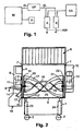
- Fig. 1 indicates a plant according to the invention schematically in the form of a block diagram.
- the mixer M is designed as a vacuum mixer. It is, for example, top loadable and, as described with reference to the other figures, hermetically sealed by a hood and is connected to an exhaust duct AL, which is connected to a vacuum pump VP. Furthermore, a heating device H is provided, with which the introduced mixture is heated, for example to about 80 ° C. With the vacuum pump VP, a vacuum is generated in the mixer housing, for example between 100 and 2 mbar. The extracted air is supplied via the exhaust air line AL to the two capacitors K, in which condenses the steam contained wastewater AW.
- This waste water AW can then be collected directly into a sewer connection or in a condensate tank and then fed to a sewer with the aid of valve technology.
- the capacitors are commercially available capacitors that are connected to a cooling system KA, generated by the cooling liquid is, which flows around the condensation tube in the condenser K and cools.
- a particularly suitable mixer is in Fig. 2 shown.
- This has a base 1, which is displaceable by means of wheels 22 on the ground.
- This can also be mounted a support plate for the other units.
- an attached housing of the mixer is arranged vertically adjustable in the vertical direction. This makes it possible to spend the mixer housing in different working heights relative to the ground or in different height positions relative to the underframe 1.
- the marking of the heating channels and the supply line for the heating medium has been dispensed with.
- no extraction nozzles are shown, which are connected via the exhaust duct to the vacuum pump, which in turn is connected to the capacitors.
- the carrying element of the mixer is the mixing trough 25, which is part of the housing and at the bottom of a semicircular bottom trough 5 and straight or slightly conically opening upwardly extending walls.
- the mixing trough is closed at the front by an end wall 3 and at the rear by an end wall 4 and is made of stainless steel, for example.
- the outer round coiled mixing vanes 17, 17 ' are introduced, which are rotatably mounted on the end faces 3 and 4, in such a way that the mixing vanes are guided at a small distance above the half-shell-shaped base 5 or adjacent, so that For example, scheduled scrapers can slide along the bottom wall.
- the mixing vanes 17, 17 ' are fastened on both sides to connecting rods 19 or a respective flange 19, 22, which is mounted centrally.
- a shaft such as a hollow shaft
- a controllable electric motor 11 for example via a transmission, or is directly coupled thereto.
- the motor puts in the bearings in the end faces 3 and 4 mounted outer wings 17, 17 'in a rotary motion.
- the wings are helical, with the pitch of the helix, the length and the total length of the wings are based on the capacity of the mixing trough.
- the rotating helical wings for example, the filled mix is transported from left to right in the mixing trough 25 in the right turn; opposes in reverse rotation.
- the wings throw up the mix, so that even upwards taken Mischgut, eg meat chunks, in the interior of the outer mixing vanes 17, 17 'may fall.
- the outer mixing blade assembly 17, 17 ' which in this case consists of two wings, a further inner wing assembly is provided, which in the embodiment according to Fig. 2 also consists of continuous helical mixing blades 18, which are each turned twice in itself, consist of flat material and have an inclination.
- This holding webs or annular flanges 20, 21 are rotatably mounted centrally and may include Bankwasswasserverteiler or collector, the right wing ends mounted with the annular flange 20 rotatably mounted on the holder 19 and there provided annular flange for the outer wing or rotatable on the shaft are mounted, which drives the outer mixing vanes, while the mixing vanes are mounted on the left side with the support flange 21 at a through the support assembly or the annular flange 22 inserted through shaft, which transmits the rotational movement to the inner mixing vanes.
- the shaft is part of the drive motor 12, which is mounted laterally. Also, this engine should be conveniently a controllable engine.
- the control motor 12 is housed in a housing 10 which is laterally attached to the end wall 4.
- the speeds of the outer mixing vanes between approx. 5 to 40 rpm and that of the inner vanes between approx. 10 to 80 rpm.
- the inner mixing vanes 18 and 18 ' should rotate faster than the outer mixing vanes in the opposite direction thereto, so that the mix, as it is transported from left to right through the outer mixing vanes, is transported through the inner from right to left or at reverse rotation in the opposite direction. As a result, a longitudinal flow and backflow of the mixed material are ensured with simultaneous moisture release.
- the housing has at the top pivot bearing 7, which serve to pivotally support a vacuum hood 6.
- This vacuum hood 6 may, for example, have a vacuum indicator, as well as the connecting piece for the exhaust air line. It can also be provided a viewing window to allow insight during the mixing and drying process in the mixing drum. Also, a protective grid can be interposed, through which the mix can be filled. This can also be carried out with aufaufklappbar. For loading, the vacuum hood 6 can be opened and the material entered.
- the vacuum hood 6 also offers the possibility that with the closing or opening electrical switching devices can be controlled, which can only start the engines when the vacuum hood 6 is in the closed position, so that access to the rotating mixing blades is not possible.
- a microwave generator can also be arranged in the vacuum hood as an additional or sole heating device. This can also be integrated in the side walls be arranged. It has been shown that when the microwave generator generates microwaves in the range of 2.5 GHz, a rapid heating of the mixed material, and above all, an internal heating is optimally possible, even if the mixing blades or shafts are made of metal.
- an infrared radiation source can also be used, which can be integrated in the vacuum hood 6 or positioned at another location of the housing. It has proven to be particularly advantageous to generate infrared light waves in the range from 2 to 6 ⁇ m, in order to achieve good heat introduction into the mix.
- Fig. 3 is schematically illustrated a variant in which a motor or a motor coupling is provided on one side of the housing.
- the other parts of the housing and the base are not shown.
- the outer wings 17 and 17 ' act in the same way as in accordance with Fig. 2
- the inner wing in this case consists of a beater blade, which rotates much faster, but nevertheless is able to suck the material in the same way as the inner mixing blades 18, 18 'according to FIG Fig.
- the wings are rotatably mounted in a housing with a cylindrical shape, for example, has an opening for loading.
- a change holder 27 can be provided for the impact knife 26, so that other knife arrangements or wing arrangements can also be plugged on if necessary.
- Such a change device can serve to be able to make a quick change of the wing arrangements.
- the nested central bearings for the rotary drive of the outer wings 17 and 17 'and the impact blade 26 are also shown schematically.
- the embodiment in FIG. 3 further shows that the shaft 38 for the flywheel 26 can be arranged continuously.
- On the shaft different beater blades 26 are arranged.
- the left beater blade is shown opposite directed, which should symbolize that the knife can be arranged not only acting in a direction of flow, but also opposite, for example, to achieve a vortex flow with simultaneous crushing.
- Fig. 4 is partially in section the area of the mixer according to Fig. 2 shown, in which the discharge opening 13 is provided in the end wall 3 of the mixing trough 25. From the figure it can also be seen that the deflector plate 15 is provided in extension to the bottom 5 of the mixing trough 25.
- the flap 14 Before the discharge opening 13, the flap 14 is located in Verschier ein. This flap is pivotally mounted about an upper pivot bearing 37, which extends horizontally, and can be pivoted to the left. Deviating from the embodiment according to Fig. 2 the flap 14 is actuated via a toggle lever lock.
- This toggle closure consists of a first lever 31 which is pivotally mounted via a pivot bearing 30 on the flap 14 and is pivotally connected at its other end via a bearing 32 to a lever arm 33 which is part of an angled actuating rod 34 which is a pivot bearing 35th in the angular range on the inside of the outer wall of the Attachment 8 is hinged.
- the actuating rod if it is bow-shaped and has two rods, engages through bearing slots 36 in the outer wall.
- a slider for closing the opening 13 may be provided, which is then to operate via a corresponding mechanism.
- a pivoting slide, which is moved via a rotating mechanism may be provided, which releases the opening 13, for example, in a round design.
- a collecting container of a filling installation or packing installation can be brought into position under the emptying opening. It is also possible To fill the emptying material directly in hermetically sealed bags directly, which are then sealed, for example, vacuum sealed. Again, the expert opens up various possibilities to pack the dried masses and / or continue to transport and process.
- a system according to the invention can be electronically controlled in a fully controlled manner such that the heating process, the vacuum pump and the condensate drain are controlled on the one hand and controlled on the other hand, for example, when opening the vacuum hood, the processes interrupted and then continued again after closing or during the emptying process the processing processes are terminated.
Landscapes
- Engineering & Computer Science (AREA)
- Chemical & Material Sciences (AREA)
- General Engineering & Computer Science (AREA)
- Mechanical Engineering (AREA)
- Chemical Kinetics & Catalysis (AREA)
- Organic Chemistry (AREA)
- Oil, Petroleum & Natural Gas (AREA)
- Molecular Biology (AREA)
- Life Sciences & Earth Sciences (AREA)
- Health & Medical Sciences (AREA)
- Drying Of Solid Materials (AREA)
- Processing Of Solid Wastes (AREA)
- Mixers Of The Rotary Stirring Type (AREA)
- Accessories For Mixers (AREA)
- Crushing And Pulverization Processes (AREA)
Priority Applications (1)
| Application Number | Priority Date | Filing Date | Title |
|---|---|---|---|
| PL08707144T PL2115356T3 (pl) | 2007-01-25 | 2008-01-21 | Instalacja do suszenia mas organicznych |
Applications Claiming Priority (2)
| Application Number | Priority Date | Filing Date | Title |
|---|---|---|---|
| DE202007001123U DE202007001123U1 (de) | 2007-01-25 | 2007-01-25 | Anlage zum Trocknen von organischen Massen |
| PCT/EP2008/000411 WO2008089931A1 (de) | 2007-01-25 | 2008-01-21 | Anlage zum trocknen von organischen massen |
Publications (2)
| Publication Number | Publication Date |
|---|---|
| EP2115356A1 EP2115356A1 (de) | 2009-11-11 |
| EP2115356B1 true EP2115356B1 (de) | 2013-07-03 |
Family
ID=38170373
Family Applications (1)
| Application Number | Title | Priority Date | Filing Date |
|---|---|---|---|
| EP08707144.5A Active EP2115356B1 (de) | 2007-01-25 | 2008-01-21 | Anlage zum trocknen von organischen massen |
Country Status (11)
| Country | Link |
|---|---|
| US (1) | US8561314B2 (pl) |
| EP (1) | EP2115356B1 (pl) |
| JP (1) | JP2010516454A (pl) |
| CN (1) | CN101680658B (pl) |
| BR (1) | BRPI0806726A2 (pl) |
| DE (1) | DE202007001123U1 (pl) |
| MX (1) | MX2009007706A (pl) |
| PL (1) | PL2115356T3 (pl) |
| RU (1) | RU2450225C2 (pl) |
| UA (1) | UA71078U (pl) |
| WO (1) | WO2008089931A1 (pl) |
Families Citing this family (67)
| Publication number | Priority date | Publication date | Assignee | Title |
|---|---|---|---|---|
| WO2009013761A1 (en) * | 2007-07-23 | 2009-01-29 | Satbir Singh | Smart double ribbon screw mixer |
| KR20090099802A (ko) * | 2008-03-18 | 2009-09-23 | 모영환 | 농업용 비닐피복기 |
| KR100903745B1 (ko) * | 2008-03-18 | 2009-06-19 | 웅진코웨이주식회사 | 배출장치 및 이를 구비한 음식물 처리기의 건조로 |
| WO2010108930A2 (en) * | 2009-03-23 | 2010-09-30 | Engin Hasan Hueseyin | Laboratory type quick film drying oven |
| US9435585B2 (en) * | 2010-07-23 | 2016-09-06 | Kwok Fai Lam | Microwave dryer and microwave drying method |
| DK3369723T3 (da) * | 2011-03-02 | 2021-01-11 | Bayer Cropscience Ag | Fremgangsmåde til fremstilling af aryl- og heteroaryleddikesyrederivater |
| JP2013086028A (ja) * | 2011-10-18 | 2013-05-13 | Kansai Electric Power Co Inc:The | 食品廃棄物処理装置 |
| US9462895B2 (en) * | 2011-12-08 | 2016-10-11 | Mixmo AB | Dispensing device |
| RU2488434C1 (ru) * | 2012-02-13 | 2013-07-27 | Государственное научное учреждение Зональный научно-исследовательский институт сельского хозяйства Северо-Востока имени Н.В. Рудницкого Российской академии сельскохозяйственных наук | Смеситель |
| EP2689833A3 (en) | 2012-07-27 | 2015-05-13 | Marion Mixers, Inc. | Mixing apparatus |
| KR101491133B1 (ko) * | 2012-09-28 | 2015-02-05 | 손정기 | 마이크로웨이브를 사용하여 음식물쓰레기를 건조처리하는 장치 |
| DE102012112497A1 (de) | 2012-12-18 | 2014-07-03 | Debraqco Handels Gmbh | Verfahren, Vorrichtung und Anordnung zur Schlammtrockung |
| FR2999388B1 (fr) * | 2012-12-18 | 2016-01-01 | Lutetia | Procede de sechage de produits alimentaires |
| FR3006915B1 (fr) | 2013-06-13 | 2015-06-26 | Serveco Sa Soc | Systeme de traitement destine a deshydrater des dechets alimentaires |
| KR101501480B1 (ko) * | 2013-08-07 | 2015-03-12 | 장현지 | 음식물쓰레기 진공건조처리시스템 |
| RU2567315C2 (ru) * | 2013-12-26 | 2015-11-10 | Государственное бюджетное образовательное учреждение высшего профессионального образования Нижегородский государственный инженерно-экономический институт (НГИЭИ) | Смеситель-ферментатор |
| BR102014007763A2 (pt) * | 2014-03-31 | 2015-12-08 | Topema Cozinhas Profissionais Ind E Comerciais Ltda | aperfeiçoamento em reator para redução de resíduos alimentares orgânicos |
| EP2930153A1 (en) * | 2014-04-07 | 2015-10-14 | Nest S.r.l. | Device for the treatment of organic material |
| ES2798122T3 (es) * | 2014-05-29 | 2020-12-09 | Themis S P A | Método para transformar residuos y sistema para llevar a cabo dicho método |
| WO2017023169A2 (en) * | 2015-08-05 | 2017-02-09 | Etekin B.V. | Manure processing apparatus for the processing of poultry manure to a fertilizer |
| CL2015002875A1 (es) * | 2015-09-25 | 2016-06-10 | Hornos Ind Oven Spa | Un sistema y método en las modalidades de cilindro rotatorio, cilindro con tornillo sin fin y batea o poliedro para deshidratar, secar y/o desinfectar deshechos de las industrias: pesquera, de alimentos (en base a productos animales o vegetales), riles, relaves, lodos y todo tipo de desechos domésticos y/o todo tipo de material, basura o desecho. |
| CN106839693A (zh) * | 2015-12-04 | 2017-06-13 | 潘珺珺 | 一种颗粒物料烘干机 |
| DK3414505T3 (da) * | 2016-02-10 | 2021-04-12 | Hedinn Hf | Mekanisk damprekompressionsindretning |
| RU2638978C2 (ru) * | 2016-02-15 | 2017-12-19 | Федеральное государственное бюджетное научное учреждение "Зональный научно-исследовательский институт сельского хозяйства Северо-Востока имени Н.В. Рудницкого" | Смеситель |
| USD1027351S1 (en) | 2016-03-09 | 2024-05-14 | Whirlpool Corporation | Food recycler |
| US9895726B1 (en) | 2016-07-27 | 2018-02-20 | Whirlpool Corporation | Method for cleaning a food waste recycling bin of a food waste recycling appliance |
| RU2655351C2 (ru) * | 2016-07-01 | 2018-05-25 | Государственное бюджетное образовательное учреждение высшего образования Нижегородский государственный инженерно-экономический университет (НГИЭУ) | Смеситель сухих сыпучих и влажных рассыпных кормов |
| US20180017323A1 (en) * | 2016-07-13 | 2018-01-18 | John Potee Whitney | Heat exchanger with thermal fluid-containing shaft and shaft-riding auger for solids and slurries |
| CN107772196A (zh) * | 2016-08-30 | 2018-03-09 | 东钜能源科技实业有限公司 | 真空干燥萃取系统及其操作方法 |
| EP3535535B1 (en) * | 2016-11-02 | 2021-05-19 | Hedinn Hf. | Combined cooker and dryer device |
| KR101796760B1 (ko) | 2017-07-31 | 2017-11-10 | 이도경 | 음식물 쓰레기 건조처리장치 |
| JP7211708B2 (ja) * | 2018-01-30 | 2023-01-24 | 水ing株式会社 | 汚泥乾燥システム |
| RU2705692C1 (ru) * | 2018-02-12 | 2019-11-11 | Сергей Анатольевич Ермаков | Комплекс для вакуумной сублимационной сушки |
| EP3755164A1 (en) * | 2018-02-20 | 2020-12-30 | Société des Produits Nestlé S.A. | Food processing system and associated method |
| RU2681387C1 (ru) * | 2018-03-05 | 2019-03-06 | Владислав Григорьевич Вохмянин | Сушилка барабанного типа |
| US11369937B2 (en) | 2019-02-10 | 2022-06-28 | Dwight Eric Kinzer | Electromagnetic reactor |
| US12550233B2 (en) | 2019-02-10 | 2026-02-10 | Dwight Kinzer | Method of operating an electromagnetic reactor |
| KR20210135486A (ko) | 2019-03-08 | 2021-11-15 | 샤크닌자 오퍼레이팅 엘엘씨 | 진공 식품 가공 시스템 |
| JP2022516278A (ja) | 2019-03-08 | 2022-02-25 | シャークニンジャ オペレーティング エルエルシー | 真空食品加工システム |
| US11304565B2 (en) | 2019-03-08 | 2022-04-19 | Sharkninja Operating Llc | Vacuum food processing system |
| DE102019108869A1 (de) | 2019-04-04 | 2020-10-08 | Maschinenfabrik Gustav Eirich Gmbh & Co. Kg | Mischer mit Verschlussdeckel |
| CN110094949B (zh) * | 2019-05-29 | 2024-02-23 | 福建省轻工机械设备有限公司 | 一种物料干燥设备 |
| USD925270S1 (en) | 2019-06-06 | 2021-07-20 | Sharkninja Operating Llc | Blender |
| USD940500S1 (en) | 2019-06-06 | 2022-01-11 | Sharkninja Operating Llc | Lid |
| USD927256S1 (en) | 2019-06-06 | 2021-08-10 | Sharkninja Operating Llc | Blender |
| USD924007S1 (en) | 2019-06-06 | 2021-07-06 | Sharkninja Operating Llc | Strainer blender accessory |
| JP6956966B2 (ja) * | 2019-08-30 | 2021-11-02 | マイクロ波化学株式会社 | 焙煎カカオ豆、および生カカオ豆の焙煎方法 |
| CN111595107A (zh) * | 2020-05-08 | 2020-08-28 | 上海悠漪环保科技有限公司 | 一种滚动式远红外烘干机 |
| CN111765722A (zh) * | 2020-06-18 | 2020-10-13 | 张斌 | 一种用于煤化工的智能烘干设备 |
| CN111872047B (zh) * | 2020-07-30 | 2023-06-30 | 合肥海闻自动化设备有限公司 | 微波预处理系统和具有该系统的餐厨垃圾处理设备 |
| CN112254436A (zh) * | 2020-10-01 | 2021-01-22 | 李洪伟 | 一种混凝土膨胀剂生产用烘干设备 |
| CN112197547B (zh) * | 2020-10-25 | 2022-08-30 | 宜昌兴越新材料有限公司 | 一种新材料干燥机 |
| CN112755832A (zh) * | 2020-12-28 | 2021-05-07 | 宜都国阳机电设备有限公司 | 一种搅拌翻转装置 |
| GB202100276D0 (en) * | 2021-01-08 | 2021-02-24 | Uplifting Priducts Ltd | Rotational device |
| JP2022151041A (ja) * | 2021-03-26 | 2022-10-07 | 株式会社北川鉄工所 | ミキサ及び被混合物の混合方法 |
| CN113019189A (zh) * | 2021-03-26 | 2021-06-25 | 湖南钐河科技有限公司 | 纸箱加工用制糊装置 |
| CN113154800B (zh) * | 2021-04-26 | 2023-08-01 | 南京三美农业发展有限公司 | 一种有机肥料无公害处理装置及其处理方法 |
| RU207286U1 (ru) * | 2021-07-09 | 2021-10-21 | Общество с ограниченной ответственностью «МИРРИКО» | Сушильный модуль |
| CN113856854A (zh) * | 2021-09-26 | 2021-12-31 | 山东省农业机械科学研究院 | 一种机收膜杂混合物组合刀式破碎装置及方法 |
| US20230288141A1 (en) * | 2022-03-13 | 2023-09-14 | Jason Womack | Food Waste Dehydrator Apparatus and Methods of Use |
| CN114754564B (zh) * | 2022-05-13 | 2023-05-30 | 江苏格兰特干燥浓缩设备有限公司 | 一种低能耗管束干燥机及其使用方法 |
| CN115069721B (zh) * | 2022-05-13 | 2023-12-26 | 华电电力科学研究院有限公司 | 一种可燃废弃物处理装置及方法 |
| CN115430338A (zh) * | 2022-08-10 | 2022-12-06 | 山东克曼特新能源科技发展有限公司 | 一种基于真空技术的新材料生产装置 |
| CN115597340A (zh) * | 2022-10-17 | 2023-01-13 | 北京国润伟业科技中心(有限合伙)(Cn) | 一种水洗飞灰间接干燥的系统和方法 |
| CN116123862B (zh) * | 2023-01-10 | 2025-11-07 | 扬州日发生物设备有限公司 | 一种u形弯列管换热器及流化床 |
| CN116832693A (zh) * | 2023-06-09 | 2023-10-03 | 华中科技大学 | 基于气化渣、固废热解半焦的多源燃料掺配系统及方法 |
| CN120172625B (zh) * | 2025-03-24 | 2025-09-19 | 北控(杭州)生态环境投资有限公司 | 一种微波热解干化污泥方法 |
Family Cites Families (105)
| Publication number | Priority date | Publication date | Assignee | Title |
|---|---|---|---|---|
| US1825261A (en) * | 1928-04-12 | 1931-09-29 | Jabez Burns & Sons Inc | Mixing apparatus |
| US2858795A (en) * | 1954-05-24 | 1958-11-04 | British Insulated Callenders | Apparatus for drying and impregnating small articles |
| US3142546A (en) * | 1962-01-22 | 1964-07-28 | John N Coats | Kiln disintegrator |
| US3194504A (en) * | 1962-09-07 | 1965-07-13 | Patterson Ind Inc | Mixing machine |
| DE1985834U (de) | 1967-02-09 | 1968-05-22 | Fernando Fina | Vakuummischer, insbesondere fuer zahntechnische anwendungen. |
| FR2006889A1 (pl) * | 1968-04-25 | 1970-01-02 | Leybold Heraeus Verwaltung | |
| US3497452A (en) * | 1968-09-09 | 1970-02-24 | Kostas Savas Arvanitakis | Method and apparatus for clarifying a liquid |
| US3672958A (en) * | 1970-02-09 | 1972-06-27 | Mc Graw Edison Co | Industrial dry cleaning cooker-still |
| US3759879A (en) * | 1971-05-28 | 1973-09-18 | Firestone Tire & Rubber Co | Continuous bulk polymerization process for vinyl chloride copolymers |
| US3777095A (en) * | 1972-05-15 | 1973-12-04 | Tokyo Shibaura Electric Co | Microwave heating apparatus |
| US3997406A (en) * | 1973-10-19 | 1976-12-14 | Kostas Savas Arvanitakis | Evaporating apparatus |
| GB1484643A (en) * | 1975-03-27 | 1977-09-01 | Jude Eng Inc | Heat exchange apparatus |
| GB1585584A (en) * | 1976-06-08 | 1981-03-04 | Kobe Steel Ltd | Process and apparatus for heating solid materials containing volatile matter |
| US4410433A (en) * | 1977-06-22 | 1983-10-18 | Arvanitakis Kostas S | Vertical filter system |
| US4177575A (en) * | 1977-09-19 | 1979-12-11 | Cannon Limited | Organic material treatment process |
| US4330946A (en) * | 1980-09-23 | 1982-05-25 | Ralph S. Tillitt | High efficiency material drying |
| US4389794A (en) * | 1980-12-23 | 1983-06-28 | Bitterly Jack G | Vacuum chamber and method of creating a vacuum |
| US4876802A (en) * | 1983-12-21 | 1989-10-31 | Gerhard Gergely | Process and means for the heat treatment of powdery or granulate material |
| DK155468C (da) * | 1984-10-04 | 1989-08-14 | Atlas As | Toerreapparat omfattende et stationaert hus og en rotor med et antal ringformede toerrelegemer |
| US4615801A (en) * | 1984-10-29 | 1986-10-07 | Lee Chung Y | Rotary filtration means in the filth condensation-dehydration apparatus |
| GB8517798D0 (en) * | 1985-07-15 | 1985-08-21 | Din Eng Ltd | Reaction chamber conveyor |
| US4733607A (en) * | 1985-10-07 | 1988-03-29 | Star Leonard J | Food processing machine |
| US4698917A (en) * | 1986-05-02 | 1987-10-13 | Italvacuum Di Ing. P. Debolini & C. S.A.S. | Rotary drier for drying heat-sensitive products and pharmaceuticals |
| US4882851A (en) * | 1987-04-13 | 1989-11-28 | The Fitzpatrick Co. | Apparatus and method for batch drying using a microwave vacuum system |
| CN87210067U (zh) * | 1987-07-11 | 1988-04-13 | 长春市英俊工商公司 | 家畜禽废弃物熔炼装置 |
| US4856203A (en) * | 1988-01-15 | 1989-08-15 | The Fitzpatrick Company | Microwave vacuum dryer |
| US4954681A (en) * | 1988-05-31 | 1990-09-04 | Kawata Co., Ltd. | Drying and crystallizing apparatus for granules, which employs a microwave device |
| KR0140525B1 (ko) * | 1989-02-03 | 1998-06-01 | 미다 가쓰시게 | 고점성물질의 제조장치 및 제조방법 |
| US5228987A (en) * | 1989-06-09 | 1993-07-20 | Hydro-Tek, Inc. | Method and apparatus for clarifying liquids |
| US5047123A (en) * | 1989-06-09 | 1991-09-10 | Hydro-Tek, Inc. | Apparatus for clarifying liquids |
| US5078836A (en) * | 1989-07-21 | 1992-01-07 | Hogan Jim S | Method and apparatus for retorting material |
| JPH03135491A (ja) * | 1989-10-19 | 1991-06-10 | Arima Moderu:Kk | ドライディスポーザ |
| US5142998A (en) * | 1989-11-28 | 1992-09-01 | Feitel Frederick E | Apparatus and method for treating contaminated gas emissions |
| US5080581A (en) * | 1991-04-10 | 1992-01-14 | Combustion Design Corporation | Method and apparatus for drying waste materials |
| US5143626A (en) * | 1990-07-10 | 1992-09-01 | Sludge Drying Systems, Inc. | Sludge dehydrater having specially designed augers and infrared heater elements |
| US5121699A (en) * | 1991-02-12 | 1992-06-16 | Frank Lowell C | Reclamation method and apparatus for soil and other products |
| US5083506A (en) * | 1991-03-06 | 1992-01-28 | Blentech Corporation | Continuous compartmented mixer |
| US5229010A (en) * | 1991-07-01 | 1993-07-20 | Progressive Recovery, Inc. | Rotating microwave contaminated materials treating apparatus and method of using thereof |
| US5117771A (en) * | 1991-08-23 | 1992-06-02 | Vanguard Environmental, Inc. | Method and apparatus to decontaminate soil |
| DK170944B1 (da) | 1991-10-14 | 1996-03-25 | Cour Administration A S Pindst | Fremgangsmåde til fremstilling af et brændselsprodukt ved tørring af et blandingsprodukt bestående af slam og et brændbart materiale samt anlæg til brug ved fremgangsmåden |
| JP2649131B2 (ja) * | 1992-11-18 | 1997-09-03 | 神鋼パンテツク株式会社 | 攪拌装置及びこれに使用するボトムリボン翼 |
| US5433020A (en) * | 1993-04-29 | 1995-07-18 | Altos Engineering, Inc. | Apparatus and method for vacuum drying |
| US5299865A (en) * | 1993-05-03 | 1994-04-05 | Hayes & Stolz Industrial Manufacturing Company Inc. | Counterpoise helical ribbon mixer |
| US7001629B1 (en) * | 1993-05-11 | 2006-02-21 | Archimex | Method and plant for solvent-free microwave extraction of natural products |
| US5852882A (en) * | 1993-09-02 | 1998-12-29 | Riviana Foods, Inc. | Food drying apparatus |
| FI962764A7 (fi) * | 1994-01-07 | 1996-08-07 | Thermtech As | Menetelmä ja laite orgaanisten ja/tai epäorgaanisten materiaalien kuiv atuksessa |
| IT1273100B (it) * | 1994-03-31 | 1997-07-04 | Paolo Debolini | Essicatore, in particolare per prodotti granulari o polverulenti |
| DE4430951C1 (de) * | 1994-08-31 | 1996-05-23 | Bayer Ag | Verfahren und Vorrichtung zur Abtrennung eines festen Rückstandes aus seiner Lösung im gerührten Gutbett |
| JPH08136137A (ja) * | 1994-11-14 | 1996-05-31 | Tousei Denki Kk | 含水物乾燥処理装置 |
| DE19507181C2 (de) | 1995-03-02 | 1998-07-30 | Guenter Krueger | Vorrichtung zum Mischen oder Kneten von organischen oder anorganischen Massen oder Teig |
| US5681481A (en) * | 1995-05-18 | 1997-10-28 | Rdp Company | Process and apparatus for liquid sludge stabilization |
| US5869810A (en) * | 1995-05-23 | 1999-02-09 | Victor Reynolds | Impedance-heated furnace |
| US5987770A (en) * | 1995-10-31 | 1999-11-23 | Kajima Corporation | Steam recompression type vacuum drying apparatus |
| US5886326A (en) * | 1996-01-19 | 1999-03-23 | Thermotrex Corporation | Microwave waste incinerator |
| US5741066A (en) * | 1996-10-15 | 1998-04-21 | Hayes & Stolz Industrial Manufacturing Company Inc. | Helical ribbon mixer |
| US5851361A (en) * | 1996-11-25 | 1998-12-22 | Hogan; Jim S. | Apparatus for processing an organic solid |
| JPH10258265A (ja) * | 1996-11-30 | 1998-09-29 | Shiiratsuku Corp:Kk | 有機性廃棄物の高速真空乾燥発酵方法 |
| JP3347963B2 (ja) * | 1996-12-11 | 2002-11-20 | 株式会社松本機械製作所 | 真空回転乾燥機 |
| US5839674A (en) * | 1997-02-05 | 1998-11-24 | Ellis; C. Mitchell | Apparatus and process for decompressing blocks of particulate materials such as blocks of compressed horticultural materials |
| US5869817A (en) * | 1997-03-06 | 1999-02-09 | General Mills, Inc. | Tunable cavity microwave applicator |
| US5924861A (en) * | 1997-08-28 | 1999-07-20 | Maumee Research & Engineering, Incorporated | Furnace discharge assembly |
| US6139793A (en) * | 1997-09-05 | 2000-10-31 | Hydroclave Systems Corporation | Waste treatment control system |
| US6079118A (en) * | 1998-01-23 | 2000-06-27 | Kiyokawa; Shin | Continuous drying system |
| RU2127627C1 (ru) * | 1998-07-21 | 1999-03-20 | Открытое акционерное общество "Научно-исследовательский и конструкторский институт химического машиностроения" | Система и вакуумный центробежный дистиллятор для регенерации воды из мочи на борту космического летательного аппарата |
| US6012447A (en) * | 1998-07-29 | 2000-01-11 | Stimsonite Corporation | Heated mixing kettle with dual acting agitators |
| JP3773675B2 (ja) * | 1998-10-28 | 2006-05-10 | 株式会社松井製作所 | 粉粒体材料の真空式自動連続除湿乾燥装置 |
| US6092301A (en) * | 1998-11-13 | 2000-07-25 | Komanowsky; Michael | Microwave drying of hides under vacuum in tanning equipment |
| JP2000202413A (ja) * | 1999-01-14 | 2000-07-25 | Shoji Kurosawa | 生ごみ処理装置 |
| SE518999C2 (sv) * | 1999-03-01 | 2002-12-17 | Milproc Miljoeprocesser Ab | Förfarande för att hygienisera och torka organiskt material |
| US6270708B1 (en) * | 1999-03-12 | 2001-08-07 | Tamer International, Ltd. | Agglomerating and drying apparatus |
| US6143221A (en) * | 1999-03-12 | 2000-11-07 | Tamer International, Ltd. | Agglomerating and drying apparatus |
| GB9909630D0 (en) * | 1999-04-28 | 1999-06-23 | Zeneca Ltd | Reactor |
| US6380517B2 (en) * | 1999-06-21 | 2002-04-30 | Cabot Corporation | High temperature rotating vacuum kiln and method for heat treating solid particulate material under a vacuum |
| ATE266324T1 (de) * | 1999-11-06 | 2004-05-15 | Darrell C Horn | Kontinuierlicher misch- oder ruehrfrittierkocher |
| RU2168921C1 (ru) * | 1999-12-06 | 2001-06-20 | Кубанский государственный технологический университет | Сушильный барабан для табачного волокна |
| JP4545880B2 (ja) * | 2000-05-16 | 2010-09-15 | 株式会社泉精器製作所 | 固液分離装置 |
| US6299774B1 (en) * | 2000-06-26 | 2001-10-09 | Jack L. Ainsworth | Anaerobic digester system |
| US6619214B2 (en) * | 2001-06-20 | 2003-09-16 | Karen Meyer Bertram | Method and apparatus for treatment of waste |
| RU2280500C2 (ru) * | 2001-07-06 | 2006-07-27 | Вейнберг Вениамин Яковлевич | Технологическая установка |
| US6754978B1 (en) * | 2001-10-13 | 2004-06-29 | Micronics, L.L.C. | Vacuum treatment of waste stream |
| US7140122B1 (en) * | 2001-10-13 | 2006-11-28 | Micronics, Llc | Vacuum treatment of waste stream with anti-incrustation measures |
| US6470593B1 (en) * | 2001-11-01 | 2002-10-29 | Delta Medical Co., Ltd. | Ejector device for vacuum drying |
| DE10359379B4 (de) * | 2002-12-28 | 2010-10-28 | Backhaus, Martin, Dipl.-Ing. | Schraubenbandmischer |
| CN2611841Y (zh) * | 2003-04-02 | 2004-04-14 | 卢顺从 | 真空萃取冷冻干燥机 |
| US6892471B2 (en) * | 2003-07-02 | 2005-05-17 | Anders T. Ragnarsson | Sludge dryer |
| DE102004005961B4 (de) * | 2003-12-11 | 2005-11-24 | Hecht Anlagenbau Gmbh | Verfahren zur kontaminationsvermeidenden Entleerung bzw. Befüllung von Schüttgutbehältern |
| US7669349B1 (en) * | 2004-03-04 | 2010-03-02 | TD*X Associates LP | Method separating volatile components from feed material |
| JP4474506B2 (ja) * | 2004-04-12 | 2010-06-09 | 財団法人北九州産業学術推進機構 | マイクロ波を用いた減圧乾燥方法及びその装置 |
| CN2706725Y (zh) * | 2004-05-24 | 2005-06-29 | 卢顺从 | 真空冷冻搅拌干燥装置 |
| DE102004034395A1 (de) * | 2004-07-16 | 2006-02-16 | Bayer Technology Services Gmbh | Dynamischer Mischer |
| WO2006117934A1 (ja) * | 2005-04-27 | 2006-11-09 | Mitsubishi Kakoki Kaisha, Ltd. | 有機性廃棄物の処理設備および処理方法 |
| KR20050046706A (ko) * | 2005-04-28 | 2005-05-18 | 김수동 | 마이크로웨이브를 이용한 음식물쓰레기 처리장치 |
| JP2007160581A (ja) * | 2005-12-12 | 2007-06-28 | Star Seiki Co Ltd | 樹脂ペレットの除湿乾燥装置及びその方法 |
| MX2008007748A (es) * | 2005-12-14 | 2009-02-10 | Mobilestream Oil Inc | Recuperacion a base de microondas de hidrocarburos y comestibles fosiles. |
| US7585105B2 (en) * | 2006-06-05 | 2009-09-08 | Apache Stainless Equipment Corporation | Scraper assembly |
| CN200958892Y (zh) * | 2006-08-24 | 2007-10-10 | 天水华圆制药设备科技有限责任公司 | 多层连续式真空微波干燥设备 |
| US8015841B2 (en) * | 2006-09-08 | 2011-09-13 | Praxair Technology, Inc. | Cryogenic refrigeration system for lyophilization |
| US8065815B2 (en) * | 2006-10-10 | 2011-11-29 | Rdp Technologies, Inc. | Apparatus, method and system for treating sewage sludge |
| JP4435799B2 (ja) * | 2007-03-19 | 2010-03-24 | 東京エレクトロン株式会社 | 開閉バルブ及び該開閉バルブを備えた処理装置 |
| EP2028258A1 (en) * | 2007-08-01 | 2009-02-25 | N.V. Desmet Ballestra Engineering S.A. | Process for equipment for desolventising under reduced pressure |
| MX355861B (es) * | 2007-10-15 | 2018-05-03 | Enwave Corp | Aparato y método para el secado en vacío de materiales orgánicos con microondas. |
| US20090113751A1 (en) * | 2007-11-01 | 2009-05-07 | Shi-Yu Teng | Infrared dryer |
| US8168043B2 (en) * | 2008-08-29 | 2012-05-01 | Eau-Viron Incorporated | Retort apparatus and method for continuously processing liquid and solid mixtures and for recovering products therefrom |
| US8020314B2 (en) * | 2008-10-31 | 2011-09-20 | Corning Incorporated | Methods and apparatus for drying ceramic green bodies with microwaves |
| EP2424970A4 (en) * | 2009-04-28 | 2014-08-13 | Enwave Corp | DEVICE AND METHOD FOR DRAINING BIOLOGICAL MATERIALS |
-
2007
- 2007-01-25 DE DE202007001123U patent/DE202007001123U1/de not_active Expired - Lifetime
-
2008
- 2008-01-21 CN CN2008800026998A patent/CN101680658B/zh not_active Expired - Fee Related
- 2008-01-21 RU RU2009124099/03A patent/RU2450225C2/ru not_active IP Right Cessation
- 2008-01-21 WO PCT/EP2008/000411 patent/WO2008089931A1/de not_active Ceased
- 2008-01-21 US US12/524,291 patent/US8561314B2/en active Active
- 2008-01-21 JP JP2009546678A patent/JP2010516454A/ja active Pending
- 2008-01-21 PL PL08707144T patent/PL2115356T3/pl unknown
- 2008-01-21 BR BRPI0806726-0A patent/BRPI0806726A2/pt not_active IP Right Cessation
- 2008-01-21 EP EP08707144.5A patent/EP2115356B1/de active Active
- 2008-01-21 MX MX2009007706A patent/MX2009007706A/es active IP Right Grant
- 2008-01-21 UA UAA200906422U patent/UA71078U/ru unknown
Also Published As
| Publication number | Publication date |
|---|---|
| PL2115356T3 (pl) | 2013-11-29 |
| DE202007001123U1 (de) | 2007-06-06 |
| CN101680658A (zh) | 2010-03-24 |
| MX2009007706A (es) | 2009-10-12 |
| US8561314B2 (en) | 2013-10-22 |
| RU2009124099A (ru) | 2011-02-27 |
| UA71078U (ru) | 2012-07-10 |
| BRPI0806726A2 (pt) | 2011-09-06 |
| US20100132210A1 (en) | 2010-06-03 |
| EP2115356A1 (de) | 2009-11-11 |
| WO2008089931A1 (de) | 2008-07-31 |
| CN101680658B (zh) | 2013-07-10 |
| RU2450225C2 (ru) | 2012-05-10 |
| JP2010516454A (ja) | 2010-05-20 |
Similar Documents
| Publication | Publication Date | Title |
|---|---|---|
| EP2115356B1 (de) | Anlage zum trocknen von organischen massen | |
| DE69312690T2 (de) | Verfahren, vorrichtung und anlage zur extraktion, durch verdampfung eines festen rückstandes aus einem fliessfähigen material | |
| DE602004002884T2 (de) | Vorrichtung zum Behandeln von Müll und dafür vorgesehene Schneideinrichtung | |
| DE69314430T2 (de) | Trocknungsvorrichtung | |
| DE69413283T2 (de) | Müllbehandlungsvorrichtung | |
| EP2831198B1 (de) | Vorrichtung und verfahren zur katalytischen depolymerisation von kohlenwasserstoff enthaltendem material | |
| WO2013127792A1 (de) | Verfahren und vorrichtung zur grosstechnischen aufbereitung von biomasse für die energiegewinnung | |
| EP0277507A2 (de) | Desinfektionsanlage für kontaminierten Krankenhausmüll | |
| EP4208431B1 (de) | Kompostiervorrichtung | |
| DE4315074B4 (de) | Verfahren und Vorrichtung zum Entwässern von Schlämmen | |
| EP1162260A2 (de) | Kofermentationsanlage | |
| DE19507181C2 (de) | Vorrichtung zum Mischen oder Kneten von organischen oder anorganischen Massen oder Teig | |
| DE69903845T2 (de) | Verfahren und vorrichtung zur zersetzung organischer abfälle | |
| DE19523842C2 (de) | Abfallbeseitigungsvorrichtung, insbesondere zur Beseitigung von biologisch abbaubaren Küchen- und Haushaltsabfällen | |
| CN116967197B (zh) | 一种黄芩除草剂的制备装置及制备方法 | |
| EP0543097B1 (de) | Verfahren und Vorrichtung zur biologischen Umwandlung organischer Stoffe in Biomasse | |
| EP4311821B1 (de) | Komposter und verfahren zur umwandlung von organischem material in kompost in einem komposter | |
| DE2456134C2 (de) | Vorrichtung zur Beseitigung und Verwertung von Müll und Klärschlamm | |
| CN220111920U (zh) | 垃圾粉碎设备和厨余垃圾桶 | |
| KR100269858B1 (ko) | 음식물 쓰레기 가공처리장치 | |
| AT523084A1 (de) | Vorrichtung zum Zerkleinern von Abfällen | |
| KR200469115Y1 (ko) | 음식물 쓰레기 중량 감소장치 | |
| KR20020088129A (ko) | 음식물 쓰레기 건조기 | |
| DE2419835A1 (de) | Zerkleinerungsmaschine | |
| DE202022102467U1 (de) | Heizeinrichtung und Heizsystem |
Legal Events
| Date | Code | Title | Description |
|---|---|---|---|
| PUAI | Public reference made under article 153(3) epc to a published international application that has entered the european phase |
Free format text: ORIGINAL CODE: 0009012 |
|
| 17P | Request for examination filed |
Effective date: 20090811 |
|
| AK | Designated contracting states |
Kind code of ref document: A1 Designated state(s): AT BE BG CH CY CZ DE DK EE ES FI FR GB GR HR HU IE IS IT LI LT LU LV MC MT NL NO PL PT RO SE SI SK TR |
|
| DAX | Request for extension of the european patent (deleted) | ||
| 17Q | First examination report despatched |
Effective date: 20101123 |
|
| REG | Reference to a national code |
Ref country code: DE Ref legal event code: R079 Ref document number: 502008010229 Country of ref document: DE Free format text: PREVIOUS MAIN CLASS: F23G0005040000 Ipc: F26B0005040000 |
|
| GRAP | Despatch of communication of intention to grant a patent |
Free format text: ORIGINAL CODE: EPIDOSNIGR1 |
|
| RIC1 | Information provided on ipc code assigned before grant |
Ipc: C10L 5/46 20060101ALI20130111BHEP Ipc: B01F 15/00 20060101ALI20130111BHEP Ipc: C10L 5/44 20060101ALI20130111BHEP Ipc: F26B 5/04 20060101AFI20130111BHEP Ipc: F26B 11/16 20060101ALI20130111BHEP Ipc: B01F 7/08 20060101ALI20130111BHEP Ipc: F26B 1/00 20060101ALI20130111BHEP Ipc: F26B 25/00 20060101ALI20130111BHEP Ipc: B01F 13/06 20060101ALI20130111BHEP Ipc: F23G 5/04 20060101ALI20130111BHEP |
|
| GRAS | Grant fee paid |
Free format text: ORIGINAL CODE: EPIDOSNIGR3 |
|
| GRAA | (expected) grant |
Free format text: ORIGINAL CODE: 0009210 |
|
| AK | Designated contracting states |
Kind code of ref document: B1 Designated state(s): AT BE BG CH CY CZ DE DK EE ES FI FR GB GR HR HU IE IS IT LI LT LU LV MC MT NL NO PL PT RO SE SI SK TR |
|
| REG | Reference to a national code |
Ref country code: GB Ref legal event code: FG4D Free format text: NOT ENGLISH |
|
| REG | Reference to a national code |
Ref country code: AT Ref legal event code: REF Ref document number: 620016 Country of ref document: AT Kind code of ref document: T Effective date: 20130715 Ref country code: CH Ref legal event code: EP |
|
| REG | Reference to a national code |
Ref country code: IE Ref legal event code: FG4D Free format text: LANGUAGE OF EP DOCUMENT: GERMAN |
|
| REG | Reference to a national code |
Ref country code: DE Ref legal event code: R096 Ref document number: 502008010229 Country of ref document: DE Effective date: 20130829 |
|
| PG25 | Lapsed in a contracting state [announced via postgrant information from national office to epo] |
Ref country code: SI Free format text: LAPSE BECAUSE OF FAILURE TO SUBMIT A TRANSLATION OF THE DESCRIPTION OR TO PAY THE FEE WITHIN THE PRESCRIBED TIME-LIMIT Effective date: 20130703 |
|
| REG | Reference to a national code |
Ref country code: PL Ref legal event code: T3 |
|
| REG | Reference to a national code |
Ref country code: NL Ref legal event code: VDEP Effective date: 20130703 |
|
| REG | Reference to a national code |
Ref country code: LT Ref legal event code: MG4D |
|
| PG25 | Lapsed in a contracting state [announced via postgrant information from national office to epo] |
Ref country code: CY Free format text: LAPSE BECAUSE OF FAILURE TO SUBMIT A TRANSLATION OF THE DESCRIPTION OR TO PAY THE FEE WITHIN THE PRESCRIBED TIME-LIMIT Effective date: 20130814 Ref country code: NO Free format text: LAPSE BECAUSE OF FAILURE TO SUBMIT A TRANSLATION OF THE DESCRIPTION OR TO PAY THE FEE WITHIN THE PRESCRIBED TIME-LIMIT Effective date: 20131003 Ref country code: HR Free format text: LAPSE BECAUSE OF FAILURE TO SUBMIT A TRANSLATION OF THE DESCRIPTION OR TO PAY THE FEE WITHIN THE PRESCRIBED TIME-LIMIT Effective date: 20130703 Ref country code: SE Free format text: LAPSE BECAUSE OF FAILURE TO SUBMIT A TRANSLATION OF THE DESCRIPTION OR TO PAY THE FEE WITHIN THE PRESCRIBED TIME-LIMIT Effective date: 20130703 Ref country code: IS Free format text: LAPSE BECAUSE OF FAILURE TO SUBMIT A TRANSLATION OF THE DESCRIPTION OR TO PAY THE FEE WITHIN THE PRESCRIBED TIME-LIMIT Effective date: 20131103 Ref country code: PT Free format text: LAPSE BECAUSE OF FAILURE TO SUBMIT A TRANSLATION OF THE DESCRIPTION OR TO PAY THE FEE WITHIN THE PRESCRIBED TIME-LIMIT Effective date: 20131104 Ref country code: LT Free format text: LAPSE BECAUSE OF FAILURE TO SUBMIT A TRANSLATION OF THE DESCRIPTION OR TO PAY THE FEE WITHIN THE PRESCRIBED TIME-LIMIT Effective date: 20130703 |
|
| PG25 | Lapsed in a contracting state [announced via postgrant information from national office to epo] |
Ref country code: GR Free format text: LAPSE BECAUSE OF FAILURE TO SUBMIT A TRANSLATION OF THE DESCRIPTION OR TO PAY THE FEE WITHIN THE PRESCRIBED TIME-LIMIT Effective date: 20131004 Ref country code: NL Free format text: LAPSE BECAUSE OF FAILURE TO SUBMIT A TRANSLATION OF THE DESCRIPTION OR TO PAY THE FEE WITHIN THE PRESCRIBED TIME-LIMIT Effective date: 20130703 Ref country code: LV Free format text: LAPSE BECAUSE OF FAILURE TO SUBMIT A TRANSLATION OF THE DESCRIPTION OR TO PAY THE FEE WITHIN THE PRESCRIBED TIME-LIMIT Effective date: 20130703 Ref country code: ES Free format text: LAPSE BECAUSE OF FAILURE TO SUBMIT A TRANSLATION OF THE DESCRIPTION OR TO PAY THE FEE WITHIN THE PRESCRIBED TIME-LIMIT Effective date: 20131014 Ref country code: FI Free format text: LAPSE BECAUSE OF FAILURE TO SUBMIT A TRANSLATION OF THE DESCRIPTION OR TO PAY THE FEE WITHIN THE PRESCRIBED TIME-LIMIT Effective date: 20130703 |
|
| PG25 | Lapsed in a contracting state [announced via postgrant information from national office to epo] |
Ref country code: CY Free format text: LAPSE BECAUSE OF FAILURE TO SUBMIT A TRANSLATION OF THE DESCRIPTION OR TO PAY THE FEE WITHIN THE PRESCRIBED TIME-LIMIT Effective date: 20130703 |
|
| PG25 | Lapsed in a contracting state [announced via postgrant information from national office to epo] |
Ref country code: EE Free format text: LAPSE BECAUSE OF FAILURE TO SUBMIT A TRANSLATION OF THE DESCRIPTION OR TO PAY THE FEE WITHIN THE PRESCRIBED TIME-LIMIT Effective date: 20130703 Ref country code: RO Free format text: LAPSE BECAUSE OF FAILURE TO SUBMIT A TRANSLATION OF THE DESCRIPTION OR TO PAY THE FEE WITHIN THE PRESCRIBED TIME-LIMIT Effective date: 20130703 Ref country code: CZ Free format text: LAPSE BECAUSE OF FAILURE TO SUBMIT A TRANSLATION OF THE DESCRIPTION OR TO PAY THE FEE WITHIN THE PRESCRIBED TIME-LIMIT Effective date: 20130703 Ref country code: DK Free format text: LAPSE BECAUSE OF FAILURE TO SUBMIT A TRANSLATION OF THE DESCRIPTION OR TO PAY THE FEE WITHIN THE PRESCRIBED TIME-LIMIT Effective date: 20130703 Ref country code: SK Free format text: LAPSE BECAUSE OF FAILURE TO SUBMIT A TRANSLATION OF THE DESCRIPTION OR TO PAY THE FEE WITHIN THE PRESCRIBED TIME-LIMIT Effective date: 20130703 |
|
| PLBE | No opposition filed within time limit |
Free format text: ORIGINAL CODE: 0009261 |
|
| STAA | Information on the status of an ep patent application or granted ep patent |
Free format text: STATUS: NO OPPOSITION FILED WITHIN TIME LIMIT |
|
| 26N | No opposition filed |
Effective date: 20140404 |
|
| REG | Reference to a national code |
Ref country code: DE Ref legal event code: R097 Ref document number: 502008010229 Country of ref document: DE Effective date: 20140404 |
|
| BERE | Be: lapsed |
Owner name: INOTEC G.M.B.H. & CO. HOLDING UND HANDELS KG Effective date: 20140131 |
|
| PG25 | Lapsed in a contracting state [announced via postgrant information from national office to epo] |
Ref country code: MC Free format text: LAPSE BECAUSE OF FAILURE TO SUBMIT A TRANSLATION OF THE DESCRIPTION OR TO PAY THE FEE WITHIN THE PRESCRIBED TIME-LIMIT Effective date: 20130703 Ref country code: LU Free format text: LAPSE BECAUSE OF FAILURE TO SUBMIT A TRANSLATION OF THE DESCRIPTION OR TO PAY THE FEE WITHIN THE PRESCRIBED TIME-LIMIT Effective date: 20140121 |
|
| REG | Reference to a national code |
Ref country code: CH Ref legal event code: PL |
|
| PG25 | Lapsed in a contracting state [announced via postgrant information from national office to epo] |
Ref country code: LI Free format text: LAPSE BECAUSE OF NON-PAYMENT OF DUE FEES Effective date: 20140131 Ref country code: CH Free format text: LAPSE BECAUSE OF NON-PAYMENT OF DUE FEES Effective date: 20140131 |
|
| REG | Reference to a national code |
Ref country code: IE Ref legal event code: MM4A |
|
| REG | Reference to a national code |
Ref country code: FR Ref legal event code: PLFP Year of fee payment: 8 |
|
| PG25 | Lapsed in a contracting state [announced via postgrant information from national office to epo] |
Ref country code: BE Free format text: LAPSE BECAUSE OF NON-PAYMENT OF DUE FEES Effective date: 20140131 Ref country code: IE Free format text: LAPSE BECAUSE OF NON-PAYMENT OF DUE FEES Effective date: 20140121 |
|
| REG | Reference to a national code |
Ref country code: AT Ref legal event code: MM01 Ref document number: 620016 Country of ref document: AT Kind code of ref document: T Effective date: 20140121 |
|
| PG25 | Lapsed in a contracting state [announced via postgrant information from national office to epo] |
Ref country code: AT Free format text: LAPSE BECAUSE OF NON-PAYMENT OF DUE FEES Effective date: 20140121 |
|
| PGFP | Annual fee paid to national office [announced via postgrant information from national office to epo] |
Ref country code: FR Payment date: 20150122 Year of fee payment: 8 Ref country code: GB Payment date: 20150121 Year of fee payment: 8 |
|
| REG | Reference to a national code |
Ref country code: DE Ref legal event code: R082 Ref document number: 502008010229 Country of ref document: DE Representative=s name: PATENTANWAELTE UND RECHTSANWALT DR. WEISS, ARA, DE Ref country code: DE Ref legal event code: R082 Ref document number: 502008010229 Country of ref document: DE Representative=s name: PATENTANWAELTE UND RECHTSANWALT WEISS, ARAT & , DE |
|
| PG25 | Lapsed in a contracting state [announced via postgrant information from national office to epo] |
Ref country code: MT Free format text: LAPSE BECAUSE OF FAILURE TO SUBMIT A TRANSLATION OF THE DESCRIPTION OR TO PAY THE FEE WITHIN THE PRESCRIBED TIME-LIMIT Effective date: 20130703 |
|
| PG25 | Lapsed in a contracting state [announced via postgrant information from national office to epo] |
Ref country code: BG Free format text: LAPSE BECAUSE OF FAILURE TO SUBMIT A TRANSLATION OF THE DESCRIPTION OR TO PAY THE FEE WITHIN THE PRESCRIBED TIME-LIMIT Effective date: 20130703 |
|
| PG25 | Lapsed in a contracting state [announced via postgrant information from national office to epo] |
Ref country code: TR Free format text: LAPSE BECAUSE OF FAILURE TO SUBMIT A TRANSLATION OF THE DESCRIPTION OR TO PAY THE FEE WITHIN THE PRESCRIBED TIME-LIMIT Effective date: 20130703 Ref country code: HU Free format text: LAPSE BECAUSE OF FAILURE TO SUBMIT A TRANSLATION OF THE DESCRIPTION OR TO PAY THE FEE WITHIN THE PRESCRIBED TIME-LIMIT; INVALID AB INITIO Effective date: 20080121 |
|
| GBPC | Gb: european patent ceased through non-payment of renewal fee |
Effective date: 20160121 |
|
| REG | Reference to a national code |
Ref country code: FR Ref legal event code: ST Effective date: 20160930 |
|
| PG25 | Lapsed in a contracting state [announced via postgrant information from national office to epo] |
Ref country code: GB Free format text: LAPSE BECAUSE OF NON-PAYMENT OF DUE FEES Effective date: 20160121 |
|
| PG25 | Lapsed in a contracting state [announced via postgrant information from national office to epo] |
Ref country code: FR Free format text: LAPSE BECAUSE OF NON-PAYMENT OF DUE FEES Effective date: 20160201 |
|
| REG | Reference to a national code |
Ref country code: DE Ref legal event code: R082 Ref document number: 502008010229 Country of ref document: DE Representative=s name: PATENTANWAELTE UND RECHTSANWALT WEISS, ARAT & , DE Ref country code: DE Ref legal event code: R081 Ref document number: 502008010229 Country of ref document: DE Owner name: INOTEC GMBH MASCHINENENTWICKLUNG UND VERTRIEB, DE Free format text: FORMER OWNER: INOTEC GMBH & CO. HOLDING UND HANDELS-KG, 72770 REUTLINGEN, DE |
|
| PGFP | Annual fee paid to national office [announced via postgrant information from national office to epo] |
Ref country code: DE Payment date: 20250326 Year of fee payment: 18 |
|
| PGFP | Annual fee paid to national office [announced via postgrant information from national office to epo] |
Ref country code: PL Payment date: 20250120 Year of fee payment: 18 |
|
| PGFP | Annual fee paid to national office [announced via postgrant information from national office to epo] |
Ref country code: IT Payment date: 20250128 Year of fee payment: 18 |