EP2115356B1 - Installation for drying organic matter - Google Patents
Installation for drying organic matter Download PDFInfo
- Publication number
- EP2115356B1 EP2115356B1 EP08707144.5A EP08707144A EP2115356B1 EP 2115356 B1 EP2115356 B1 EP 2115356B1 EP 08707144 A EP08707144 A EP 08707144A EP 2115356 B1 EP2115356 B1 EP 2115356B1
- Authority
- EP
- European Patent Office
- Prior art keywords
- mixing
- mixer
- mixing blade
- installation according
- heating device
- Prior art date
- Legal status (The legal status is an assumption and is not a legal conclusion. Google has not performed a legal analysis and makes no representation as to the accuracy of the status listed.)
- Active
Links
- 238000001035 drying Methods 0.000 title claims description 14
- 238000009434 installation Methods 0.000 title claims description 14
- 239000005416 organic matter Substances 0.000 title claims description 10
- 238000002156 mixing Methods 0.000 claims description 119
- 238000010438 heat treatment Methods 0.000 claims description 29
- 239000000463 material Substances 0.000 claims description 18
- XLYOFNOQVPJJNP-UHFFFAOYSA-N water Substances O XLYOFNOQVPJJNP-UHFFFAOYSA-N 0.000 claims description 10
- 238000001816 cooling Methods 0.000 claims description 7
- 239000010794 food waste Substances 0.000 claims description 5
- 239000010806 kitchen waste Substances 0.000 claims description 5
- 238000011049 filling Methods 0.000 claims description 4
- 239000002028 Biomass Substances 0.000 claims description 3
- 238000004806 packaging method and process Methods 0.000 claims description 3
- 239000010902 straw Substances 0.000 claims description 3
- 238000000605 extraction Methods 0.000 claims description 2
- 230000005855 radiation Effects 0.000 claims description 2
- 238000007790 scraping Methods 0.000 claims 1
- 239000000203 mixture Substances 0.000 description 33
- 238000000034 method Methods 0.000 description 16
- 230000008569 process Effects 0.000 description 16
- 241000196324 Embryophyta Species 0.000 description 11
- 230000000694 effects Effects 0.000 description 7
- 230000008901 benefit Effects 0.000 description 6
- 230000008859 change Effects 0.000 description 6
- 239000002699 waste material Substances 0.000 description 6
- 238000011068 loading method Methods 0.000 description 5
- 239000003990 capacitor Substances 0.000 description 4
- 238000013461 design Methods 0.000 description 4
- 230000033001 locomotion Effects 0.000 description 4
- 238000012545 processing Methods 0.000 description 4
- 239000002351 wastewater Substances 0.000 description 4
- 238000009833 condensation Methods 0.000 description 3
- 230000005494 condensation Effects 0.000 description 3
- 239000000446 fuel Substances 0.000 description 3
- 239000008236 heating water Substances 0.000 description 3
- 230000007246 mechanism Effects 0.000 description 3
- 239000002184 metal Substances 0.000 description 3
- 235000019645 odor Nutrition 0.000 description 3
- 239000010801 sewage sludge Substances 0.000 description 3
- 241000533293 Sesbania emerus Species 0.000 description 2
- 238000004140 cleaning Methods 0.000 description 2
- 239000002131 composite material Substances 0.000 description 2
- 239000000110 cooling liquid Substances 0.000 description 2
- 230000008878 coupling Effects 0.000 description 2
- 238000010168 coupling process Methods 0.000 description 2
- 238000005859 coupling reaction Methods 0.000 description 2
- 230000001419 dependent effect Effects 0.000 description 2
- 238000010586 diagram Methods 0.000 description 2
- 239000010791 domestic waste Substances 0.000 description 2
- 238000001704 evaporation Methods 0.000 description 2
- 230000008020 evaporation Effects 0.000 description 2
- 238000002474 experimental method Methods 0.000 description 2
- 238000004898 kneading Methods 0.000 description 2
- 230000009965 odorless effect Effects 0.000 description 2
- 239000010802 sludge Substances 0.000 description 2
- 241000894006 Bacteria Species 0.000 description 1
- 239000000853 adhesive Substances 0.000 description 1
- 230000001070 adhesive effect Effects 0.000 description 1
- 239000002154 agricultural waste Substances 0.000 description 1
- 230000000712 assembly Effects 0.000 description 1
- 238000000429 assembly Methods 0.000 description 1
- 239000011230 binding agent Substances 0.000 description 1
- 230000005540 biological transmission Effects 0.000 description 1
- 238000005266 casting Methods 0.000 description 1
- 238000009826 distribution Methods 0.000 description 1
- 230000035622 drinking Effects 0.000 description 1
- 238000005516 engineering process Methods 0.000 description 1
- 210000003608 fece Anatomy 0.000 description 1
- 238000000855 fermentation Methods 0.000 description 1
- 230000004151 fermentation Effects 0.000 description 1
- 235000013305 food Nutrition 0.000 description 1
- 238000003780 insertion Methods 0.000 description 1
- 230000037431 insertion Effects 0.000 description 1
- 235000021190 leftovers Nutrition 0.000 description 1
- 239000007788 liquid Substances 0.000 description 1
- 239000010871 livestock manure Substances 0.000 description 1
- 238000004519 manufacturing process Methods 0.000 description 1
- 235000013372 meat Nutrition 0.000 description 1
- 230000002906 microbiologic effect Effects 0.000 description 1
- 235000013379 molasses Nutrition 0.000 description 1
- 239000010813 municipal solid waste Substances 0.000 description 1
- 238000005457 optimization Methods 0.000 description 1
- 239000011368 organic material Substances 0.000 description 1
- 239000010815 organic waste Substances 0.000 description 1
- 238000012856 packing Methods 0.000 description 1
- 239000010893 paper waste Substances 0.000 description 1
- 239000008188 pellet Substances 0.000 description 1
- 238000003825 pressing Methods 0.000 description 1
- 230000001681 protective effect Effects 0.000 description 1
- 235000021251 pulses Nutrition 0.000 description 1
- 238000007789 sealing Methods 0.000 description 1
- 239000002002 slurry Substances 0.000 description 1
- 239000007787 solid Substances 0.000 description 1
- 229910001220 stainless steel Inorganic materials 0.000 description 1
- 239000010935 stainless steel Substances 0.000 description 1
- 230000001954 sterilising effect Effects 0.000 description 1
- 238000004659 sterilization and disinfection Methods 0.000 description 1
- 238000003756 stirring Methods 0.000 description 1
- 239000008399 tap water Substances 0.000 description 1
- 235000020679 tap water Nutrition 0.000 description 1
- 239000002641 tar oil Substances 0.000 description 1
- 238000012549 training Methods 0.000 description 1
- 230000007704 transition Effects 0.000 description 1
- 239000002023 wood Substances 0.000 description 1
- 239000002916 wood waste Substances 0.000 description 1
Images

Classifications
-
- F—MECHANICAL ENGINEERING; LIGHTING; HEATING; WEAPONS; BLASTING
- F23—COMBUSTION APPARATUS; COMBUSTION PROCESSES
- F23G—CREMATION FURNACES; CONSUMING WASTE PRODUCTS BY COMBUSTION
- F23G5/00—Incineration of waste; Incinerator constructions; Details, accessories or control therefor
- F23G5/02—Incineration of waste; Incinerator constructions; Details, accessories or control therefor with pretreatment
- F23G5/04—Incineration of waste; Incinerator constructions; Details, accessories or control therefor with pretreatment drying
-
- B—PERFORMING OPERATIONS; TRANSPORTING
- B01—PHYSICAL OR CHEMICAL PROCESSES OR APPARATUS IN GENERAL
- B01F—MIXING, e.g. DISSOLVING, EMULSIFYING OR DISPERSING
- B01F27/00—Mixers with rotary stirring devices in fixed receptacles; Kneaders
- B01F27/05—Stirrers
- B01F27/11—Stirrers characterised by the configuration of the stirrers
- B01F27/114—Helically shaped stirrers, i.e. stirrers comprising a helically shaped band or helically shaped band sections
- B01F27/1142—Helically shaped stirrers, i.e. stirrers comprising a helically shaped band or helically shaped band sections of the corkscrew type
-
- B—PERFORMING OPERATIONS; TRANSPORTING
- B01—PHYSICAL OR CHEMICAL PROCESSES OR APPARATUS IN GENERAL
- B01F—MIXING, e.g. DISSOLVING, EMULSIFYING OR DISPERSING
- B01F27/00—Mixers with rotary stirring devices in fixed receptacles; Kneaders
- B01F27/60—Mixers with rotary stirring devices in fixed receptacles; Kneaders with stirrers rotating about a horizontal or inclined axis
- B01F27/72—Mixers with rotary stirring devices in fixed receptacles; Kneaders with stirrers rotating about a horizontal or inclined axis with helices or sections of helices
- B01F27/726—Mixers with rotary stirring devices in fixed receptacles; Kneaders with stirrers rotating about a horizontal or inclined axis with helices or sections of helices with two helices with opposite pitch on the same shaft; with two helices on the same axis, driven in opposite directions or at different speeds
-
- B—PERFORMING OPERATIONS; TRANSPORTING
- B01—PHYSICAL OR CHEMICAL PROCESSES OR APPARATUS IN GENERAL
- B01F—MIXING, e.g. DISSOLVING, EMULSIFYING OR DISPERSING
- B01F33/00—Other mixers; Mixing plants; Combinations of mixers
- B01F33/70—Mixers specially adapted for working at sub- or super-atmospheric pressure, e.g. combined with de-foaming
-
- B—PERFORMING OPERATIONS; TRANSPORTING
- B01—PHYSICAL OR CHEMICAL PROCESSES OR APPARATUS IN GENERAL
- B01F—MIXING, e.g. DISSOLVING, EMULSIFYING OR DISPERSING
- B01F35/00—Accessories for mixers; Auxiliary operations or auxiliary devices; Parts or details of general application
- B01F35/45—Closures or doors specially adapted for mixing receptacles; Operating mechanisms therefor
- B01F35/451—Closures or doors specially adapted for mixing receptacles; Operating mechanisms therefor by rotating them about an axis parallel to the plane of the opening
-
- C—CHEMISTRY; METALLURGY
- C10—PETROLEUM, GAS OR COKE INDUSTRIES; TECHNICAL GASES CONTAINING CARBON MONOXIDE; FUELS; LUBRICANTS; PEAT
- C10L—FUELS NOT OTHERWISE PROVIDED FOR; NATURAL GAS; SYNTHETIC NATURAL GAS OBTAINED BY PROCESSES NOT COVERED BY SUBCLASSES C10G, C10K; LIQUEFIED PETROLEUM GAS; ADDING MATERIALS TO FUELS OR FIRES TO REDUCE SMOKE OR UNDESIRABLE DEPOSITS OR TO FACILITATE SOOT REMOVAL; FIRELIGHTERS
- C10L5/00—Solid fuels
- C10L5/40—Solid fuels essentially based on materials of non-mineral origin
- C10L5/44—Solid fuels essentially based on materials of non-mineral origin on vegetable substances
-
- C—CHEMISTRY; METALLURGY
- C10—PETROLEUM, GAS OR COKE INDUSTRIES; TECHNICAL GASES CONTAINING CARBON MONOXIDE; FUELS; LUBRICANTS; PEAT
- C10L—FUELS NOT OTHERWISE PROVIDED FOR; NATURAL GAS; SYNTHETIC NATURAL GAS OBTAINED BY PROCESSES NOT COVERED BY SUBCLASSES C10G, C10K; LIQUEFIED PETROLEUM GAS; ADDING MATERIALS TO FUELS OR FIRES TO REDUCE SMOKE OR UNDESIRABLE DEPOSITS OR TO FACILITATE SOOT REMOVAL; FIRELIGHTERS
- C10L5/00—Solid fuels
- C10L5/40—Solid fuels essentially based on materials of non-mineral origin
- C10L5/46—Solid fuels essentially based on materials of non-mineral origin on sewage, house, or town refuse
-
- F—MECHANICAL ENGINEERING; LIGHTING; HEATING; WEAPONS; BLASTING
- F26—DRYING
- F26B—DRYING SOLID MATERIALS OR OBJECTS BY REMOVING LIQUID THEREFROM
- F26B1/00—Preliminary treatment of solid materials or objects to facilitate drying, e.g. mixing or backmixing the materials to be dried with predominantly dry solids
- F26B1/005—Preliminary treatment of solid materials or objects to facilitate drying, e.g. mixing or backmixing the materials to be dried with predominantly dry solids by means of disintegrating, e.g. crushing, shredding, milling the materials to be dried
-
- F—MECHANICAL ENGINEERING; LIGHTING; HEATING; WEAPONS; BLASTING
- F26—DRYING
- F26B—DRYING SOLID MATERIALS OR OBJECTS BY REMOVING LIQUID THEREFROM
- F26B11/00—Machines or apparatus for drying solid materials or objects with movement which is non-progressive
- F26B11/12—Machines or apparatus for drying solid materials or objects with movement which is non-progressive in stationary drums or other mainly-closed receptacles with moving stirring devices
- F26B11/16—Machines or apparatus for drying solid materials or objects with movement which is non-progressive in stationary drums or other mainly-closed receptacles with moving stirring devices the stirring device moving in a vertical or steeply-inclined plane
-
- F—MECHANICAL ENGINEERING; LIGHTING; HEATING; WEAPONS; BLASTING
- F26—DRYING
- F26B—DRYING SOLID MATERIALS OR OBJECTS BY REMOVING LIQUID THEREFROM
- F26B25/00—Details of general application not covered by group F26B21/00 or F26B23/00
- F26B25/005—Treatment of dryer exhaust gases
- F26B25/006—Separating volatiles, e.g. recovering solvents from dryer exhaust gases
-
- F—MECHANICAL ENGINEERING; LIGHTING; HEATING; WEAPONS; BLASTING
- F26—DRYING
- F26B—DRYING SOLID MATERIALS OR OBJECTS BY REMOVING LIQUID THEREFROM
- F26B5/00—Drying solid materials or objects by processes not involving the application of heat
- F26B5/04—Drying solid materials or objects by processes not involving the application of heat by evaporation or sublimation of moisture under reduced pressure, e.g. in a vacuum
- F26B5/048—Drying solid materials or objects by processes not involving the application of heat by evaporation or sublimation of moisture under reduced pressure, e.g. in a vacuum in combination with heat developed by electro-magnetic means, e.g. microwave energy
-
- C—CHEMISTRY; METALLURGY
- C02—TREATMENT OF WATER, WASTE WATER, SEWAGE, OR SLUDGE
- C02F—TREATMENT OF WATER, WASTE WATER, SEWAGE, OR SLUDGE
- C02F11/00—Treatment of sludge; Devices therefor
- C02F11/12—Treatment of sludge; Devices therefor by de-watering, drying or thickening
- C02F11/13—Treatment of sludge; Devices therefor by de-watering, drying or thickening by heating
- C02F11/131—Treatment of sludge; Devices therefor by de-watering, drying or thickening by heating using electromagnetic or ultrasonic waves
-
- F—MECHANICAL ENGINEERING; LIGHTING; HEATING; WEAPONS; BLASTING
- F23—COMBUSTION APPARATUS; COMBUSTION PROCESSES
- F23G—CREMATION FURNACES; CONSUMING WASTE PRODUCTS BY COMBUSTION
- F23G2201/00—Pretreatment
- F23G2201/80—Shredding
-
- F—MECHANICAL ENGINEERING; LIGHTING; HEATING; WEAPONS; BLASTING
- F23—COMBUSTION APPARATUS; COMBUSTION PROCESSES
- F23G—CREMATION FURNACES; CONSUMING WASTE PRODUCTS BY COMBUSTION
- F23G2900/00—Special features of, or arrangements for incinerators
- F23G2900/50206—Pelletising waste before combustion
-
- F—MECHANICAL ENGINEERING; LIGHTING; HEATING; WEAPONS; BLASTING
- F23—COMBUSTION APPARATUS; COMBUSTION PROCESSES
- F23K—FEEDING FUEL TO COMBUSTION APPARATUS
- F23K2201/00—Pretreatment of solid fuel
- F23K2201/10—Pulverizing
- F23K2201/1006—Mills adapted for use with furnaces
-
- F—MECHANICAL ENGINEERING; LIGHTING; HEATING; WEAPONS; BLASTING
- F23—COMBUSTION APPARATUS; COMBUSTION PROCESSES
- F23K—FEEDING FUEL TO COMBUSTION APPARATUS
- F23K2201/00—Pretreatment of solid fuel
- F23K2201/20—Drying
-
- Y—GENERAL TAGGING OF NEW TECHNOLOGICAL DEVELOPMENTS; GENERAL TAGGING OF CROSS-SECTIONAL TECHNOLOGIES SPANNING OVER SEVERAL SECTIONS OF THE IPC; TECHNICAL SUBJECTS COVERED BY FORMER USPC CROSS-REFERENCE ART COLLECTIONS [XRACs] AND DIGESTS
- Y02—TECHNOLOGIES OR APPLICATIONS FOR MITIGATION OR ADAPTATION AGAINST CLIMATE CHANGE
- Y02E—REDUCTION OF GREENHOUSE GAS [GHG] EMISSIONS, RELATED TO ENERGY GENERATION, TRANSMISSION OR DISTRIBUTION
- Y02E50/00—Technologies for the production of fuel of non-fossil origin
- Y02E50/10—Biofuels, e.g. bio-diesel
-
- Y—GENERAL TAGGING OF NEW TECHNOLOGICAL DEVELOPMENTS; GENERAL TAGGING OF CROSS-SECTIONAL TECHNOLOGIES SPANNING OVER SEVERAL SECTIONS OF THE IPC; TECHNICAL SUBJECTS COVERED BY FORMER USPC CROSS-REFERENCE ART COLLECTIONS [XRACs] AND DIGESTS
- Y02—TECHNOLOGIES OR APPLICATIONS FOR MITIGATION OR ADAPTATION AGAINST CLIMATE CHANGE
- Y02E—REDUCTION OF GREENHOUSE GAS [GHG] EMISSIONS, RELATED TO ENERGY GENERATION, TRANSMISSION OR DISTRIBUTION
- Y02E50/00—Technologies for the production of fuel of non-fossil origin
- Y02E50/30—Fuel from waste, e.g. synthetic alcohol or diesel
Definitions
- the invention relates to a plant for drying organic matter, in particular kitchen and food waste or other biomasses, including those containing packaging residues, napkins, straws or the like., According to the preamble of claim 1.
- biomasses e.g. B. sewage sludge accumulating sewage sludge, liquid manure and other microbiological and renewable biomasses, especially after fermentation, after pressing in Drying ovens and burning the remaining solid components in heating plants. It is also from the DE 28 33 731 A1 It is known to mix biomass from the group of municipal solid waste, agricultural waste, food waste, paper waste, shredded wood, wood waste or other cellulosic materials with binders from the group water, sewage sludge, waste liquors, tar oil condensate, residual molasses or other starchy waste materials and to compress them into briquettes ,
- a process for producing a fuel by drying a slurry dewatered to a dry matter content of at least 15% to 30% is known.
- the dewatered sludge is mixed prior to drying with a combustible material having a lower water content than the sludge to form a composite product.
- a drying plant for heating the mixture is dried to a desired, combustible dry mass.
- the troak plant is a drum plant with a heater at one end.
- the composite product is fed directly to the heater and largely mechanically and pneumatically formed into a fuel.
- the fuel can be traded for example in the form of pellets.
- a vacuum mixer for dental applications and the like Is from the DE-AS 1 607 783 known to mix casting and / or Knetmassen together.
- apparatus for mixing and kneading of organic or inorganic masses or dough in various designs are known. These can according to U.S. Patent 3,194,504 ; Have outer mixing blades and internal mixer discs.
- U.S. Patent 1,825,261 is a coffee bean mixing machine known in which in a closed cylinder housing helical mixing blades are provided throughout to mix the coffee beans together.
- Equipment for drying organic matter are large plants. They are not suitable for hygienic processing of kitchen waste, leftovers and other waste from catering, canteen areas and food processing, so that they can be incinerated or disposed of as a dried product without release of odors. So far, the waste was collected over days or weeks in containers as malodorous mass and then disposed of in the household waste or after extensive sterilization.
- an apparatus for mixing or kneading organic or inorganic masses or dough with an elongated housing having a substantially horizontal longitudinal axis is known.
- outer and inner mixing blades are stored and driven.
- the mixing blades are designed and driven so that the outer mixing blade promotes the mix in the one longitudinal direction and the inner mixing blades the mix in the opposite direction or vice versa or the same direction promotion takes place.
- WO 00/52405 A is a plant for hygienic treatment and drying of organic waste known. This waste is traded by means of stirring elements in a vertical reactor, where it is heated in the vertical reactor by externally introduced microwave energy. Furthermore, this reactor can be evacuated.
- the invention is based on the issue to provide a system to organic matter, especially biomass as they are contaminated as kitchen and food waste, or not contaminated with napkins, drinking straws, packaging remnants, almost, odorless to be able to prepare a dry mass, which can be disposed of with household waste or incineration in a heating system or other uses or disposed of without hesitation.
- This system can be realized as a compact unit in different sizes.
- the mixer can be a 20-, 50-, 100-, 150-, 200-, 500- or 1000-liter mixer and larger, which can be mounted together with the other components on a platform or assembled into a structural unit ,
- Such a compact system can be installed, for example, in the waste rooms of a restaurant or canteen. But even larger mixers or mixers with other volumes can be used.
- the design and dimensioning are dependent on the particular application.
- a cooling unit which is electrically driven, for example, cooler tap water or other cool service water can be used in the condenser for the condensation process of the vaporized air mixture sucked out of the mixer with the vacuum pump.
- the operation is increased when an electrically driven cooling unit is used to allow the condenser to flow around the condensation tube cooled cooling liquid can.
- Any known vacuum pump can be used in the system to suck in the exhaust air from the organic matter, including any digester gas. This moisture-containing air or water vapor is then condensed in the condenser and introduced the condensate as waste water in the sewer.
- the bottom and / or side and end walls of the housing of the mixer and / or at least one mixing blade in the mixer heat the introduced organic mass by means of suitable heating devices.
- electrical heating elements may be provided, which are inserted into corresponding channels of the components.
- water-bearing channels must be provided in the building parts in a known manner or hollow, and feed lines and distributors and discharge lines with collectors must be provided in order to close the heating water circuit.
- mixer blades since they are hollow or have ducts, the supply via a hollow shaft, as well as the derivative.
- the mixer wing is then mounted on both sides of the end walls of the mixer via manifolds.
- a microwave heating device may also be used. It has been found that when introducing a Mikrowavehgenerators z. B. in the hood and when generating microwaves in the range of 2.5 GHz efficient internal heating of the mix in the mixer is also achievable, even if the mixing vanes are made of metal. Experiments by means of infrared light heating devices have furthermore shown that rapid intensive heating of the mixed material can also be achieved hereby. The best efficiency has been achieved with infrared light in the wavelength range of 2 to .6 microns. The power of the microwave generator or the infrared heat source should be adapted to the size of the mixer. Due to the closed design of the mixer with the hood of metal is in the use of radiant Heat sources at the same time given a secure shielding to the outside.
- the mixer can then be emptied through the discharge opening, wherein the organic, dried masses are crushed by the continuous mixing process on the one hand and on the other dried by the permanent removal of the gas and moisture-containing air.
- This process is virtually odorless, whereby the condensate can be routed directly into the sewer drain.
- the emptying can be done in a receptacle (mobile or stationary), in a container of a conveyor or a container of a bottling plant with which the dry mass can be filled in bags, which can be subsequently vacuum-sealed, for example, and then sealed.
- the condensate can also drain into a condensate collection, which is controlled by a controlled valve device z. B. to the sewer system is selectively connectable.
- a special embodiment of the mixer is given when two drives are provided for two centrally mounted wing assemblies or a centric flyer blade assembly, which cause in the case of mixing an opposite direction of transport of the mixed material, so that the outer mixing blades always the mix to one end of the mixing trough move, while the inner mixing blade or the beater blade to move the mix opposite in the outer mixing blades, so that with simultaneous rotation of a circular motion of the mixed material is effected from one side to the other side in the mixing trough.
- This ensures optimal mixing and release of water vapor even during a short mixing time.
- the use of a fly knife to achieve this suction to one side also causes the mix is additionally crushed.
- the propeller-like blade positions cause as well as the use of helical wings as a centric wing assembly - a suction and a pressure towards the front side.
- the pressure is released by the external worm wipers, which convey the material in the opposite direction. So it creates a mixing effect.
- the mixing effect by a mixing blade assembly according to the invention is also given when both the inner mixing blade and the outer mixing blade rotate unidirectionally.
- the mixing intensity can be substantially increased and the Mixing time can be significantly reduced when the inner and outer mixing blades rotate in opposite directions, so that the circulating flow effect described is achieved and at the same time raised parts are included in this stream.
- an accelerated mixing effect is achieved when the mixing vanes are switched in the interval, wherein expediently the interval circuits of the inner and outer wing are time-delayed.
- an inner mixing blade is fully functional even if it consists for example only of a circular arc segment, which is slightly rotated in itself.
- Such an internal mixing blade can be used both as a one-armed spiral and as a double-armed spiral.
- several such beater blades can also be mounted on a shaft which is arranged centrally within the outer mixing blade and mounted on both sides.
- the flywheel assembly is a flow direction achievable.
- the striking knives offset in the same direction, but different Flow directions causing, or even oppositely driven on different waves that are inserted into one another, be arranged to accelerate the crushing and mixing effect.
- the invention enables the person skilled in the art various possible embodiments of the optimization.
- a mixer for a plant according to the invention can thus be used as a single mixer in a conventional manner. However, it can also be done using a fly-knife assembly, which may consist of a single knife or a plurality of aligned knives, e.g. sitting distributed on a shaft over the entire length of the mixing trough, used as a crushing mixer. In addition, it is possible to be able to use the mixer as a controlled continuous mixer in a large system by appropriate coordination of the drives of the outer wing and the inner wing.
- a continuous mixer When designed as a continuous mixer, it is necessary that a part of the blade assembly of the mixer is present in a cylindrical part and a particularly long conveying blade assembly is provided to cause a mixture within this cylindrical part before the outer wings of the mixed and dried or Partially dried Carry well over the outlet opening to the next mixer.
- a continuous mixer can also be set up such that the feed of mix material takes place automatically during normal execution, as soon as a mixing process or a drying process is completed, and the mixer is emptied again.
- the mixer If the mixer to be emptied, it is only necessary to put the drive of the inner wing assembly or knife assembly out of operation or to have such transporting in the same direction, so addaddierend to control the conveying movement of the outer wing that faster emptying over the emptying opening takes place. Moreover, it is possible, during the emptying process, to let the inner arrangement of the blades or the blades rotate in a pulsed manner, so that adhesive. Mixture is thrown outwards and is detected there by the scrapers of the outer mixing blades. In the same way, the speed of the outer vanes can be increased even at the end of a discharge process, so that also adhering mixed material slides in an optimal manner to the outer edges of the outer mixing vanes.
- the ends of the mixing vanes may be interconnected to stabilize and increase mechanical strength in a paired arrangement or with uniform circumferential distribution of multiple vanes. If the connection consists of a transverse, propeller-like clearing blade extending transversely in the mixer housing, the mixed and dried masses are cleared out of the housing more quickly.
- the ends of the inner wings can be connected to each other. Instead of one of the paired wing arrangements, three or more wings may be provided, which may also be equipped with heating systems.
- the mixture is advanced from one side to the other side during mixing and is sucked back through the inner mixing vanes and at the same time also circulated.
- the mixing blades upwardly transported mix falls into the interior, so that in addition to the flow a steady admixture also good is still attached to the mixing blades good.
- an optimal mixture is also given when the feed space above the mixing blades is open.
- the mix is also not hurled outwards when the protruding housing walls are designed to extend upward above the mixing trough.
- the mixing trough may be adapted in length and / or height to desired mixer sizes, as well as the mixing blades. So mixer sizes of 100 l to 1000 l can be achieved in a simple manner only by extension or broadening.
- the rotational speed of the mixing blades can be adapted to the respective mix, eg coarse or fine.
- any desired working height can be adjusted. This is an advantage when loading manually or when loading from another machine automatically.
- the working height can be lowered so far, so that an automatic inlet from relatively low processing machines is possible or the mix can be entered by hand. In the raised position, it is possible to easily push a trolley under the side of the mixer, on which the outlet of the discharge opening is provided.
- the closure element for closing the emptying opening may be in a simple embodiment, a pivotable flap or a slider with rubber seal, which is attached to an upper horizontal pivot axis pivotally mounted on the outside of an end wall.
- the emptying opening is located in the front side.
- a toggle mechanism which is known to consist of a first lever which is pivotally mounted on the flap and pivotally connected to an actuating lever which is mounted about a fixed pivot bearing in the housing. This lever is extended beyond the pivot bearing to operate the lever, which is connected to the first pivotally mounted.
- This embodiment has the advantage that with appropriate dimensioning of the two hingedly connected levers in a lower position an over-center position can be taken, i. that the joint below the connecting line between the two linkages on the housing on the one hand and on the flap on the other hand can be spent, so that a secure, airtight closing the flap without further aids is possible.
- the wiper lip to be provided on the outer wings can be easily screwed by means of a holder.
- a wiper lip can also be pushed into a tubular receptacle provided on the outer edge.
- the lip protrudes from a slot and is held in the tubular opening, for example.
- the wiper lip may have a rear profile that corresponds to the cross section of the tubular receptacle, so that a sealed insertion is made possible, which is particularly advantageous when using organic materials has that at the mixer blades and the sealing lip and at the transition region no residues of organic matter can settle and they can be easily removed by a steam jet.
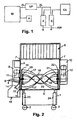
- Fig. 1 indicates a plant according to the invention schematically in the form of a block diagram.
- the mixer M is designed as a vacuum mixer. It is, for example, top loadable and, as described with reference to the other figures, hermetically sealed by a hood and is connected to an exhaust duct AL, which is connected to a vacuum pump VP. Furthermore, a heating device H is provided, with which the introduced mixture is heated, for example to about 80 ° C. With the vacuum pump VP, a vacuum is generated in the mixer housing, for example between 100 and 2 mbar. The extracted air is supplied via the exhaust air line AL to the two capacitors K, in which condenses the steam contained wastewater AW.
- This waste water AW can then be collected directly into a sewer connection or in a condensate tank and then fed to a sewer with the aid of valve technology.
- the capacitors are commercially available capacitors that are connected to a cooling system KA, generated by the cooling liquid is, which flows around the condensation tube in the condenser K and cools.
- a particularly suitable mixer is in Fig. 2 shown.
- This has a base 1, which is displaceable by means of wheels 22 on the ground.
- This can also be mounted a support plate for the other units.
- an attached housing of the mixer is arranged vertically adjustable in the vertical direction. This makes it possible to spend the mixer housing in different working heights relative to the ground or in different height positions relative to the underframe 1.
- the marking of the heating channels and the supply line for the heating medium has been dispensed with.
- no extraction nozzles are shown, which are connected via the exhaust duct to the vacuum pump, which in turn is connected to the capacitors.
- the carrying element of the mixer is the mixing trough 25, which is part of the housing and at the bottom of a semicircular bottom trough 5 and straight or slightly conically opening upwardly extending walls.
- the mixing trough is closed at the front by an end wall 3 and at the rear by an end wall 4 and is made of stainless steel, for example.
- the outer round coiled mixing vanes 17, 17 ' are introduced, which are rotatably mounted on the end faces 3 and 4, in such a way that the mixing vanes are guided at a small distance above the half-shell-shaped base 5 or adjacent, so that For example, scheduled scrapers can slide along the bottom wall.
- the mixing vanes 17, 17 ' are fastened on both sides to connecting rods 19 or a respective flange 19, 22, which is mounted centrally.
- a shaft such as a hollow shaft
- a controllable electric motor 11 for example via a transmission, or is directly coupled thereto.
- the motor puts in the bearings in the end faces 3 and 4 mounted outer wings 17, 17 'in a rotary motion.
- the wings are helical, with the pitch of the helix, the length and the total length of the wings are based on the capacity of the mixing trough.
- the rotating helical wings for example, the filled mix is transported from left to right in the mixing trough 25 in the right turn; opposes in reverse rotation.
- the wings throw up the mix, so that even upwards taken Mischgut, eg meat chunks, in the interior of the outer mixing vanes 17, 17 'may fall.
- the outer mixing blade assembly 17, 17 ' which in this case consists of two wings, a further inner wing assembly is provided, which in the embodiment according to Fig. 2 also consists of continuous helical mixing blades 18, which are each turned twice in itself, consist of flat material and have an inclination.
- This holding webs or annular flanges 20, 21 are rotatably mounted centrally and may include Bankwasswasserverteiler or collector, the right wing ends mounted with the annular flange 20 rotatably mounted on the holder 19 and there provided annular flange for the outer wing or rotatable on the shaft are mounted, which drives the outer mixing vanes, while the mixing vanes are mounted on the left side with the support flange 21 at a through the support assembly or the annular flange 22 inserted through shaft, which transmits the rotational movement to the inner mixing vanes.
- the shaft is part of the drive motor 12, which is mounted laterally. Also, this engine should be conveniently a controllable engine.
- the control motor 12 is housed in a housing 10 which is laterally attached to the end wall 4.
- the speeds of the outer mixing vanes between approx. 5 to 40 rpm and that of the inner vanes between approx. 10 to 80 rpm.
- the inner mixing vanes 18 and 18 ' should rotate faster than the outer mixing vanes in the opposite direction thereto, so that the mix, as it is transported from left to right through the outer mixing vanes, is transported through the inner from right to left or at reverse rotation in the opposite direction. As a result, a longitudinal flow and backflow of the mixed material are ensured with simultaneous moisture release.
- the housing has at the top pivot bearing 7, which serve to pivotally support a vacuum hood 6.
- This vacuum hood 6 may, for example, have a vacuum indicator, as well as the connecting piece for the exhaust air line. It can also be provided a viewing window to allow insight during the mixing and drying process in the mixing drum. Also, a protective grid can be interposed, through which the mix can be filled. This can also be carried out with aufaufklappbar. For loading, the vacuum hood 6 can be opened and the material entered.
- the vacuum hood 6 also offers the possibility that with the closing or opening electrical switching devices can be controlled, which can only start the engines when the vacuum hood 6 is in the closed position, so that access to the rotating mixing blades is not possible.
- a microwave generator can also be arranged in the vacuum hood as an additional or sole heating device. This can also be integrated in the side walls be arranged. It has been shown that when the microwave generator generates microwaves in the range of 2.5 GHz, a rapid heating of the mixed material, and above all, an internal heating is optimally possible, even if the mixing blades or shafts are made of metal.
- an infrared radiation source can also be used, which can be integrated in the vacuum hood 6 or positioned at another location of the housing. It has proven to be particularly advantageous to generate infrared light waves in the range from 2 to 6 ⁇ m, in order to achieve good heat introduction into the mix.
- Fig. 3 is schematically illustrated a variant in which a motor or a motor coupling is provided on one side of the housing.
- the other parts of the housing and the base are not shown.
- the outer wings 17 and 17 ' act in the same way as in accordance with Fig. 2
- the inner wing in this case consists of a beater blade, which rotates much faster, but nevertheless is able to suck the material in the same way as the inner mixing blades 18, 18 'according to FIG Fig.
- the wings are rotatably mounted in a housing with a cylindrical shape, for example, has an opening for loading.
- a change holder 27 can be provided for the impact knife 26, so that other knife arrangements or wing arrangements can also be plugged on if necessary.
- Such a change device can serve to be able to make a quick change of the wing arrangements.
- the nested central bearings for the rotary drive of the outer wings 17 and 17 'and the impact blade 26 are also shown schematically.
- the embodiment in FIG. 3 further shows that the shaft 38 for the flywheel 26 can be arranged continuously.
- On the shaft different beater blades 26 are arranged.
- the left beater blade is shown opposite directed, which should symbolize that the knife can be arranged not only acting in a direction of flow, but also opposite, for example, to achieve a vortex flow with simultaneous crushing.
- Fig. 4 is partially in section the area of the mixer according to Fig. 2 shown, in which the discharge opening 13 is provided in the end wall 3 of the mixing trough 25. From the figure it can also be seen that the deflector plate 15 is provided in extension to the bottom 5 of the mixing trough 25.
- the flap 14 Before the discharge opening 13, the flap 14 is located in Verschier ein. This flap is pivotally mounted about an upper pivot bearing 37, which extends horizontally, and can be pivoted to the left. Deviating from the embodiment according to Fig. 2 the flap 14 is actuated via a toggle lever lock.
- This toggle closure consists of a first lever 31 which is pivotally mounted via a pivot bearing 30 on the flap 14 and is pivotally connected at its other end via a bearing 32 to a lever arm 33 which is part of an angled actuating rod 34 which is a pivot bearing 35th in the angular range on the inside of the outer wall of the Attachment 8 is hinged.
- the actuating rod if it is bow-shaped and has two rods, engages through bearing slots 36 in the outer wall.
- a slider for closing the opening 13 may be provided, which is then to operate via a corresponding mechanism.
- a pivoting slide, which is moved via a rotating mechanism may be provided, which releases the opening 13, for example, in a round design.
- a collecting container of a filling installation or packing installation can be brought into position under the emptying opening. It is also possible To fill the emptying material directly in hermetically sealed bags directly, which are then sealed, for example, vacuum sealed. Again, the expert opens up various possibilities to pack the dried masses and / or continue to transport and process.
- a system according to the invention can be electronically controlled in a fully controlled manner such that the heating process, the vacuum pump and the condensate drain are controlled on the one hand and controlled on the other hand, for example, when opening the vacuum hood, the processes interrupted and then continued again after closing or during the emptying process the processing processes are terminated.
Description
Die Erfindung betrifft eine Anlage zum Trocken von organischen Massen, insbesondere Küchen- und Speiseabfälle oder andere Biomassen, auch solche, die Verpackungsreste, Servietten, Strohhalme oder dgl. enthalten, nach dem Oberbegriff von Anspruch 1.The invention relates to a plant for drying organic matter, in particular kitchen and food waste or other biomasses, including those containing packaging residues, napkins, straws or the like., According to the preamble of claim 1.
Es ist bekannt, zum Trocknen von Biomassen, z. B. bei der Abwasserklärung anfallende Klärschlämme, Gülle und sonstige mikrobiologische und nachwachsende Biomassen, insbesondere nach der Vergärung, nach dem Auspressen in Öfen zu trocknen und die festen Restbestandteile in Heizkraftwerken zu verbrennen. Es ist ferner aus der
Aus der
Ein Vakuummischer für zahntechnische Anwendungen und dgl. ist aus der
Die bekannten. Anlagen zur Trocknung von organischen Massen sind Großanlagen. Sie sind nicht geeignet, Küchenabfälle, Speisereste und andere im Gastronomie, Kantinenbereich und in der Lebensmittelverwertung anfallenden Abfälle hygienisch derart aufzuarbeiten, dass diese als getrocknetes Produkt - ohne Freisetzung von Gerüchen - verbrannt oder der Abfallverwertung zugeführt werden können. Bisher wurden die Abfälle über Tage oder Wochen in Behältern als übelriechende Masse gesammelt und dann über den Hausmüll oder nach aufwändiger Sterilisierung entsorgt.The well-known. Equipment for drying organic matter are large plants. They are not suitable for hygienic processing of kitchen waste, leftovers and other waste from catering, canteen areas and food processing, so that they can be incinerated or disposed of as a dried product without release of odors. So far, the waste was collected over days or weeks in containers as malodorous mass and then disposed of in the household waste or after extensive sterilization.
Aus der
Aus der
Der Erfindung liegt die Ausgabe zugrunde, eine Anlage anzugeben, um organische Massen, insbesondere Biomassen wie sie als Küchen- und Speiseabfälle, verunreinigt oder nicht verunreinigt mit Servietten, Trinkhalmen, Verpackungsresten, nahezu, geruchsfrei zu einer Trockenmasse aufbereiten zu können, die dem Hausmüll oder der Verbrennung in einer Heizanlage oder anderen Verwertungen zugeführt oder bedenkenlos entsorgt werden kann.The invention is based on the issue to provide a system to organic matter, especially biomass as they are contaminated as kitchen and food waste, or not contaminated with napkins, drinking straws, packaging remnants, almost, odorless to be able to prepare a dry mass, which can be disposed of with household waste or incineration in a heating system or other uses or disposed of without hesitation.
Die Aufgabe löst die Erfindung durch Ausgestaltung einer Anlage gemäß der Lehre des kennzeichnenden Teils von: Anspruch 1.The object is achieved by the invention by designing a system according to the teaching of the characterizing part of: claim 1.
Diese Anlage lässt sich als kompakte Einheit realisieren und zwar in verschiedenen Baugrößen. So kann der Mischer ein 20-, 50-, 100-, 150-, 200-, 500- oder 1000-Liter-Mischer und größer sein, der gemeinsam mit den weiteren Komponenten auf einer Plattform montiert oder zu einer baulichen Einheit zusammengestellt werden kann. Eine solche kompakte Anlage kann beispielsweise in den Abfallräumen eines Restaurants oder einer Kantine installiert werden. Aber auch größeres Mischer oder Mischer mit anderen Volumina können zur Anwendung kommen. Die Auslegung und Dimensionierung sind vom jeweiligen Einsatz abhängig. An Stelle eines Kühlaggregates, das beispielsweise elektrisch angetrieben wird, kann auch kühleres leitungswasser oder anderes kühles Brauchwasser, im Kondensator für den Kondensationsprozess des aus dem Mischer mit der Vakuumpumpe abgesogenen, dampfförmigen Luftgemisches verwendet werden. Die Wirkungsweise wird jedoch erhöht, wenn ein elektrisch angetriebenes Kühlaggregat verwendet wird, um in den Kondensator um das Kondensationsrohr gekühlte Kühlflüssigkeit fließen lassen zu können. In der Anlage kann jede bekannte Vakuumpumpe eingesetzt werden, um die Abluft von den organischen Massen, einschließlich eventueller Faulgase, anzusaugen. Diese feuchtigkeitshaltige Luft bzw. der Wasserdampf wird dann in dem Kondensator kondensiert und das Kondensat als Abwasser in die Kanalisation eingeleitet.This system can be realized as a compact unit in different sizes. So the mixer can be a 20-, 50-, 100-, 150-, 200-, 500- or 1000-liter mixer and larger, which can be mounted together with the other components on a platform or assembled into a structural unit , Such a compact system can be installed, for example, in the waste rooms of a restaurant or canteen. But even larger mixers or mixers with other volumes can be used. The design and dimensioning are dependent on the particular application. Instead of a cooling unit, which is electrically driven, for example, cooler tap water or other cool service water can be used in the condenser for the condensation process of the vaporized air mixture sucked out of the mixer with the vacuum pump. However, the operation is increased when an electrically driven cooling unit is used to allow the condenser to flow around the condensation tube cooled cooling liquid can. Any known vacuum pump can be used in the system to suck in the exhaust air from the organic matter, including any digester gas. This moisture-containing air or water vapor is then condensed in the condenser and introduced the condensate as waste water in the sewer.
Um den Trocknungsprozess und den Verdunstungsprozess zu beschleunigen, ist vorgesehen, dass die Boden- und/oder Seiten- und Stirnwände des Gehauses des Mischers und/oder mindestens ein Mischflügel im Mischer über geeignete Heizvorrichtungen die eingebrachte organische Masse erwärmen. Hierfür können elektrische Heizelemente vorgesehen sein, die in entsprechende Kanäle der Bauteile eingesetzt sind. Es ist aber auch eine Beheizung mittels einer Heizwasserleitung, beispielsweise von einer in dem Gebäude vorhandenen Heizleitung eingespeistes Heißwässer, möglich. In diesem Fall müssen in bekannter Weise wässerführende Kanäle in den Baüteilen vorgesehen oder diese hohl ausgebildet sowie Zuleitungen und Verteiler und Ableitungen mit Sammlern vorgesehen sein, um den Heizungswasserkreislauf zu schließen. Dies ist auch bei der Verwendung von Mischerflügeln möglich, da diese hohl sind oder Leitungskanäle aufweisen, wobei die Einspeisung über die eine Hohlwelle erfolgt, ebenso die Ableitung. Zweckmäßigerweise ist der Mischerflügel dann beidseitig an den Stirnwänden des Mischers über Verteiler gelagert.In order to accelerate the drying process and the evaporation process, it is provided that the bottom and / or side and end walls of the housing of the mixer and / or at least one mixing blade in the mixer heat the introduced organic mass by means of suitable heating devices. For this purpose, electrical heating elements may be provided, which are inserted into corresponding channels of the components. But it is also possible to heat by means of a heating water pipe, for example, from a present in the building heating pipe hot water. In this case, water-bearing channels must be provided in the building parts in a known manner or hollow, and feed lines and distributors and discharge lines with collectors must be provided in order to close the heating water circuit. This is also possible with the use of mixer blades, since they are hollow or have ducts, the supply via a hollow shaft, as well as the derivative. Conveniently, the mixer wing is then mounted on both sides of the end walls of the mixer via manifolds.
Anstelle oder ergänzend zu der beschriebenen Heizvorrichtung kann auch eine Mikrowellenheizvorrichtung zur Anwendung kommen. Es hat sich gezeigt, dass bei Einbringen eines Mikrowellehgenerators z. B. in die Haube und beim Generieren von Mikrowellen im Bereich von 2,5 GHz eine effiziente innere Erwärmung des Mischgutes in dem Mischer ebenfalls erzielbar ist, auch dann, wenn die Mischflügel aus Metall bestehen. Versuche mittels Infrarotlichtheizeinrichtungen haben ferner gezeigt, dass eine schnelle intensive Erwärmung des Mischgutes auch hierüber erzielbar ist. Die beste Effizienz ist erzielt worden mit Infrarotlicht im Wellenbereich von 2 bis .6 µm. Die Leistung des Mikrowellengenerators oder die der Infraroterwärmuhgsquelle sollte dabei der Größe des Mischers entsprechend angepasst werden. Durch die geschlossene Ausführung des Mischers mit der Haube aus Metall ist bei der Verwendung von strahlenden Wärmequellen zugleich eine sichere Abschirmung nach außen gegeben.Instead of or in addition to the described heating device, a microwave heating device may also be used. It has been found that when introducing a Mikrowavehgenerators z. B. in the hood and when generating microwaves in the range of 2.5 GHz efficient internal heating of the mix in the mixer is also achievable, even if the mixing vanes are made of metal. Experiments by means of infrared light heating devices have furthermore shown that rapid intensive heating of the mixed material can also be achieved hereby. The best efficiency has been achieved with infrared light in the wavelength range of 2 to .6 microns. The power of the microwave generator or the infrared heat source should be adapted to the size of the mixer. Due to the closed design of the mixer with the hood of metal is in the use of radiant Heat sources at the same time given a secure shielding to the outside.
Versuche haben gezeigt, dass in der Anlage sich als besonders effizient Mischer erwiesen haben, die in den Patentschriften
Vorteilhafte Ausgestaltungsformen des Mischers und der Anlage sind in den Unteransprüchen im Detail angegeben. Hierauf wird verwiesen.Advantageous embodiments of the mixer and the system are specified in the dependent claims in detail. Reference is made to this.
Eine besondere Ausgestaltung des Mischers ist dann gegeben, wenn zwei Antriebe für zwei zentrisch gelagerte Flügelanordnungen bzw. eine zentrische Schlagmesseranordnung vorgesehen sind, die im Falle des Mischens eine gegenläufige Transportrichtung des Mischgutes bewirken, so dass die äußeren Mischflügel das Mischgut stets zum einen Ende des Mischtroges bewegen, während die inneren Mischflügel bzw. das Schlagmesser das Mischgut innerhalb der äußeren Mischflügel entgegengesetzt bewegen, so dass bei gleichzeitiger Drehung eine in sich kreisende Bewegung des Mischgutes von einer Seite zur anderen Seite im Mischtrog bewirkt wird. Dadurch sind eine optimale Mischung und Freisetzung von Wasserdampf auch während einer kurzer Mischdauer gewährleistet. Die Verwendung eines Schlagmessers zum Erzielen dieses Soges nach der einen Seite bewirkt zugleich, dass das Mischgut zusätzlich zerkleinert wird. Die propellerartigen Messerstellungen bewirken dabei ebenso wie die Verwendung von schneckenförmigen Flügeln als zentrische Flügelanordnung - einen Sog und einen Druck zur Stirnseite hin. Der Druck wird jedoch von den außen liegenden Schneckenabstreifern aufgehoben, wobei diese das Material in die entgegengesetzte Richtung fördern. Es entsteht also ein Mischeffekt.A special embodiment of the mixer is given when two drives are provided for two centrally mounted wing assemblies or a centric flyer blade assembly, which cause in the case of mixing an opposite direction of transport of the mixed material, so that the outer mixing blades always the mix to one end of the mixing trough move, while the inner mixing blade or the beater blade to move the mix opposite in the outer mixing blades, so that with simultaneous rotation of a circular motion of the mixed material is effected from one side to the other side in the mixing trough. This ensures optimal mixing and release of water vapor even during a short mixing time. The use of a fly knife to achieve this suction to one side also causes the mix is additionally crushed. The propeller-like blade positions cause as well as the use of helical wings as a centric wing assembly - a suction and a pressure towards the front side. However, the pressure is released by the external worm wipers, which convey the material in the opposite direction. So it creates a mixing effect.
Der Mischeffekt durch eine Mischflügelanordnung gemäß der Erfindung ist auch dann gegeben, wenn sowohl der innere Mischflügel bzw. das Schlagmesser als auch der äußere Mischflügel sich in eine Richtung wirkend drehen. Die Mischintensität kann jedoch wesentlich erhöht und die Mischzeit wesentlich verringert werden, wenn sich die inneren und äußeren Mischflügel gegensinnig drehen, so dass der beschriebene umlaufende Strömungseffekt erzielt wird und zugleich aufgeworfene Teile in diesen Strom mit einbezogen werden. Darüber hinaus hat sich gezeigt, dass eine beschleunigte Mischwirkung erzielt wird, wenn die Mischflügel im Intervall geschaltet werden, wobei zweckmäßigerweise die Intervallschaltungen des inneren und äußeren Flügels zeitversetzt erfolgen. Darüber hinaus empfiehlt es sich, zugleich mit der Intervallschaltung auch die Drehrichtung der angetriebenen äußeren oder inneren Mischflügel zu ändern, wobei auch diese Änderung individuell gesteuert werden kann, so dass Überschneidungen der Mischgutförderungen durch die äußeren Mischflügel und inneren Mischflügel einerseits und die gegenläufige Drehrichtung andererseits ebenfalls gegeben sein können. Eine gleiche Drehrichtung, also eine gleiche Förderrichtung, beschleunigt die Mischwirkung ebenfalls. Es hat sich weiterhin als vorteilhaft erwiesen, die äußeren Mischflügel relativ breit auszuführen oder aber auch mit nach innen reichenden Kämmen zu versehen, um das Mischgut in größeren Mengen aufzuwerfen. Da die äusseren Mischflügel hohl sind, können in diesen Heizelemente oder Wasserverteiler und -sammler vorgesehen sein, um über eine Hohlwelle einen Heizwasserkreislauf zu erzielen. Weiterhin hat sich herausgestellt, dass ein innerer Mischflügel selbst dann voll funktionsfähig ist, wenn dieser beispielsweise nur aus einem Kreisbogensegment besteht, das in sich leicht gedreht ist. Ein solcher innerer Mischflügel ist sowohl als einarmige Spirale als auch als doppelarmige Spirale verwendbar. Im Falle der Verwendung von Schlagmessern können mehrere solche Schlagmesser auch auf einer Welle befestigt sein, die zentrisch innerhalb des äußeren Mischflügels angeordnet und beidseitig gelagert ist. Auch durch die Schlagmesseranordnung ist eine Strömungsrichtung erzielbar. Auch können die Schlagmesser versetzt gleichläufig, jedoch unterschiedliche Strömungsrichtungen bewirkend, oder auch entgegengesetzt angetrieben auf verschiedenen Wellen, die ineinander gesteckt sind, angeordnet sein, um den Zerkleinerungs - und Mischeffekt zu beschleunigen. Die Erfindung ermöglicht dem Fachmann hier diverse Ausführungsmöglichkeiten der Optimierung.The mixing effect by a mixing blade assembly according to the invention is also given when both the inner mixing blade and the outer mixing blade rotate unidirectionally. However, the mixing intensity can be substantially increased and the Mixing time can be significantly reduced when the inner and outer mixing blades rotate in opposite directions, so that the circulating flow effect described is achieved and at the same time raised parts are included in this stream. In addition, it has been shown that an accelerated mixing effect is achieved when the mixing vanes are switched in the interval, wherein expediently the interval circuits of the inner and outer wing are time-delayed. In addition, it is advisable to change the direction of rotation of the driven outer or inner mixing vanes at the same time as the interval circuit, wherein this change can also be controlled individually so that overlaps of the Mischgutförderungen by the outer mixing vanes and inner mixing vanes on the one hand and the opposite direction of rotation on the other can be given. A same direction of rotation, ie an identical conveying direction, also accelerates the mixing effect. It has also proven to be advantageous to perform the outer mixing blades relatively wide or to provide them with inwardly reaching ridges to raise the mix in larger quantities. Since the outer mixing blades are hollow, heating elements or water distributors and collectors can be provided in order to achieve a Heizwasserkreislauf via a hollow shaft. Furthermore, it has been found that an inner mixing blade is fully functional even if it consists for example only of a circular arc segment, which is slightly rotated in itself. Such an internal mixing blade can be used both as a one-armed spiral and as a double-armed spiral. In the case of the use of beater knives several such beater blades can also be mounted on a shaft which is arranged centrally within the outer mixing blade and mounted on both sides. Also by the flywheel assembly is a flow direction achievable. Also, the striking knives offset in the same direction, but different Flow directions causing, or even oppositely driven on different waves that are inserted into one another, be arranged to accelerate the crushing and mixing effect. The invention enables the person skilled in the art various possible embodiments of the optimization.
Ein Mischer für eine Anlage nach der Erfindung lässt sich somit als Einzelmischer in herkömmlicher Weise benutzen. Er kann jedoch auch unter Verwendung einer Schlagmesseranordnung, die aus einem einzigen Messer oder mehreren aneinandergereihten Messern bestehen kann, die z.B. auf einer Welle über die gesamte Länge des Mischtroges verteilt sitzen, als Zerkleinerungsmischer zum Einsatz kommen. Darüber hinaus ist es möglich, durch entsprechende Abstimmung der Antriebe der äußeren Flügel und der inneren Flügel den Mischer auch als gesteuerten Durchlaufmischer in einer Großanlage verwenden zu können. Bei der Ausbildung als Durchlaufmischer ist es erforderlich, dass ein Teil der Flügelanordnung des Mischers in einem zylinderförmigen Teil vorhanden ist und eine besonders lange Förderflügelanordnung vorgesehen ist, um auch innerhalb dieses zylinderförmigen Teils eine Mischung zu bewirken, bevor die äußeren Flügel das gemischte und getrocknete oder teilgetrocknete Gut über die Auslauföffnung zum nächsten Mischer befördern. Selbstverständlich kann ein Durchlaufmischer auch derart eingerichtet sein, dass die Beschickung mit Mischgut bei normaler Ausführung automatisch erfolgt, sobald ein Mischvorgang oder ein Trocknungsprozess abgeschlossen ist, und der Mischer wieder entleert wird.A mixer for a plant according to the invention can thus be used as a single mixer in a conventional manner. However, it can also be done using a fly-knife assembly, which may consist of a single knife or a plurality of aligned knives, e.g. sitting distributed on a shaft over the entire length of the mixing trough, used as a crushing mixer. In addition, it is possible to be able to use the mixer as a controlled continuous mixer in a large system by appropriate coordination of the drives of the outer wing and the inner wing. When designed as a continuous mixer, it is necessary that a part of the blade assembly of the mixer is present in a cylindrical part and a particularly long conveying blade assembly is provided to cause a mixture within this cylindrical part before the outer wings of the mixed and dried or Partially dried Carry well over the outlet opening to the next mixer. Of course, a continuous mixer can also be set up such that the feed of mix material takes place automatically during normal execution, as soon as a mixing process or a drying process is completed, and the mixer is emptied again.
Soll der Mischer entleert werden, ist es lediglich erforderlich, den Antrieb der inneren Flügelanordnung bzw. Messeranordnung außer Betrieb zu setzen oder derart in die gleiche Richtung transportierend wirken zu lassen, also hinzuaddierend zu der Förderbewegung der äußeren Flügel zu steuern, dass eine schnellere Entleerung über die Entleerungsöffnung erfolgt. Darüber hinaus ist es möglich, während des Entleerungsprozesses die innere Anordnung der Flügel bzw. der Messer pulsweise schnell rotieren zu lassen, so dass anhaftendes. Mischgut nach außen geschleudert und dort von den Abstreifern der äußeren Mischflügel erfasst wird. In gleicher Weise kann auch zum Schluss eines Entleerungsprozesses die Drehzahl der äußeren Flügel erhöht werden, so dass auch daran anhaftendes Mischgut in optimaler Weise an die Außenkanten der äußeren Mischflügel gleitet. Dies hat den Vorteil, dass praktisch kein Mischgut sich mehr in dem Mischer nach dem Entleeren befindet. Eine optimale Selbstreinigung ist sichergestellt. Eine hygienische Reinigung ist darüber hinaus auf einfache Weise möglich, wenn über Schnellkupplungen die Flügelanordnungen von den Antriebswellen nach oben abgezogen werden können.If the mixer to be emptied, it is only necessary to put the drive of the inner wing assembly or knife assembly out of operation or to have such transporting in the same direction, so addaddierend to control the conveying movement of the outer wing that faster emptying over the emptying opening takes place. Moreover, it is possible, during the emptying process, to let the inner arrangement of the blades or the blades rotate in a pulsed manner, so that adhesive. Mixture is thrown outwards and is detected there by the scrapers of the outer mixing blades. In the same way, the speed of the outer vanes can be increased even at the end of a discharge process, so that also adhering mixed material slides in an optimal manner to the outer edges of the outer mixing vanes. This has the advantage that practically no mix is more in the mixer after emptying. An optimal self-cleaning is ensured. In addition, hygienic cleaning is possible in a simple manner if the wing arrangements can be pulled off the drive shafts upwards via quick-release couplings.
Die Enden der Mischflügel können zur Stabilisierung und zur Erhöhung der mechanischen Festigkeit bei paariger Anordnung oder bei gleichmäßiger Umfangverteilung mehrerer Flügel an ihren Enden miteinander verbunden sein. Besteht die Verbindung aus einem daran befestigten quer im Mischergehäuse verlaufenden, propellerartigen Ausräumflügel, so werden die gemischten und getrockneten Massen schneller aus dem Gehäuse ausgeräumt. Auch die Enden der Innenflügel können miteinander verbunden sein. Anstelle von einer der paarigen Flügelanordnungen können auch drei oder mehrere Flügel vorgesehen sein, die auch mit Heizsystemen ausgestattet sein können.The ends of the mixing vanes may be interconnected to stabilize and increase mechanical strength in a paired arrangement or with uniform circumferential distribution of multiple vanes. If the connection consists of a transverse, propeller-like clearing blade extending transversely in the mixer housing, the mixed and dried masses are cleared out of the housing more quickly. The ends of the inner wings can be connected to each other. Instead of one of the paired wing arrangements, three or more wings may be provided, which may also be equipped with heating systems.
Durch die horizontale Anordnung des Mischtrogs und der Mischflügel wird beim Mischen das Mischgut von den äußeren Flügeln von einer Seite zur anderen Seite hin vorgeschoben und durch die inneren Mischflügel zurückgesogen und gleichzeitig auch umgewälzt. Bei diesem Vorgang fällt auch von den Mischflügeln nach oben transportiertes Mischgut in den Innenraum, so dass zusätzlich zu der Strömung eine stetige Beimischung auch noch an den Mischflügeln anhaftenden Gutes gegeben ist. Es hat sich gezeigt, dass auch eine optimale Mischung dann gegeben ist, wenn der Zuführraum oberhalb der Mischflügel offen ist. Das Mischgut wird dabei auch nicht nach außen geschleudert, wenn die überstehenden Gehäusewände oberhalb des Mischtroges nach oben verlängert ausgeführt sind. Dadurch ist es weiterhin möglich, Mischgut bis in eine Höhe einzufüllen, die höher ist als der Mischflügeldurchmesser der äußeren Mischflügel. Der Mischtrog kann in der Länge und/oder in der Höhe gewünschten Mischergrößen angepasst sein, ebenso die Mischflügel. So sind Mischergrößen von 100 l bis 1000 l auf einfache Weise nur durch Verlängerung oder Verbreiterung zu erreichen.As a result of the horizontal arrangement of the mixing trough and the mixing vanes, the mixture is advanced from one side to the other side during mixing and is sucked back through the inner mixing vanes and at the same time also circulated. In this process, also from the mixing blades upwardly transported mix falls into the interior, so that in addition to the flow a steady admixture also good is still attached to the mixing blades good. It has been shown that an optimal mixture is also given when the feed space above the mixing blades is open. The mix is also not hurled outwards when the protruding housing walls are designed to extend upward above the mixing trough. As a result, it is still possible to fill the mixture to a height which is higher than the mixing blade diameter of the outer mixing blades. The mixing trough may be adapted in length and / or height to desired mixer sizes, as well as the mixing blades. So mixer sizes of 100 l to 1000 l can be achieved in a simple manner only by extension or broadening.
Durch die einstellbaren Motoren kann die Rotationsgeschwindigkeit der Mischflügel dem jeweiligen Mischgut, z.B. grobem oder feinem, angepasst werden. Dadurch, dass das Gehäuse gegenüber dem Untergestell in vertikaler Richtung verschiebbar ist, kann jede gewünschte Arbeitshöhe eingestellt werden. Dies ist beim manuellen Beschicken oder beim automatischen Beschicken aus einer anderen Maschine von Vorteil. Die Arbeitshöhe kann dabei soweit abgesenkt werden, so dass ein automatischer Einlauf auch aus relativ niedrigen Verarbeitungsmaschinen möglich ist bzw. das Mischgut von Hand eingegeben werden kann. In der angehobenen Stellung ist es möglich, auf einfache Weise einen Transportwagen unter die Seite des Mischers zu schieben, an welcher der Auslauf der Entleerungsöffnung vorgesehen ist. Durch entsprechende Drehrichtung der äußeren Flügel wird infolge der Wendelung das Mischgut durch die geöffnete Entleerungsöffnung ausgeschoben und fällt in eine Förderanlage mit Förderband und/oder Förderschnecke, in einen Transportwagen oder in einen Sack, Beutel, Karton oder ein anderes Behältnis, das verschließbar und/oder vakuumierbar und/oder verschweißbar ist.Due to the adjustable motors, the rotational speed of the mixing blades can be adapted to the respective mix, eg coarse or fine. The fact that the housing relative to the base frame is displaced in the vertical direction, any desired working height can be adjusted. This is an advantage when loading manually or when loading from another machine automatically. The working height can be lowered so far, so that an automatic inlet from relatively low processing machines is possible or the mix can be entered by hand. In the raised position, it is possible to easily push a trolley under the side of the mixer, on which the outlet of the discharge opening is provided. By appropriate rotation of the outer wing due to the spiraling the mix is pushed out through the open discharge opening and falls into a conveyor with conveyor belt and / or screw conveyor, in a dolly or in a bag, bag, carton or other container that can be closed and / or is vacuumable and / or weldable.
Das Verschlusselement zum Verschließen der Entleerungsöffnung kann in einfacher Ausgestaltungsform eine verschwenkbare Klappe oder ein Schieber mit Gummidichtung sein, die um eine obere horizontale Schwenkachse verschwenkbar an der Außenseite einer Stirnwand befestigt ist. Die Entleerungsöffnung befindet sich in der Stirnseite. Zum Betätigen ist es zweckdienlich, einen Kniehebelmechanismus zu verwenden, der bekanntlich aus einem ersten Hebel besteht, der schwenkbeweglich an der Klappe zu befestigen und schwenkbeweglich mit einem Betätigungshebel verbunden ist, der um ein ortsfestes Drehlager im Gehäuse gelagert ist. Dieser Hebel ist über das Drehlager hinaus verlängert, um den Hebel betätigen zu können, der mit dem ersten schwenkbeweglich gelagerten verbunden ist. Diese Ausführungsform hat den Vorteil, dass bei entsprechender Dimensionierung der beiden gelenkig miteinander verbundenen Hebel in einer unteren Stellung eine Übertotpunktstellung eingenommen werden kann, d.h. dass das Gelenk unterhalb der Verbindungslinie zwischen den beiden Anlenkungen am Gehäuse einerseits und an der Klappe andererseits verbracht werden kann, so dass ein gesichertes, luftdichtes Verschließen der Klappe ohne weitere Hilfsmittel möglich ist.The closure element for closing the emptying opening may be in a simple embodiment, a pivotable flap or a slider with rubber seal, which is attached to an upper horizontal pivot axis pivotally mounted on the outside of an end wall. The emptying opening is located in the front side. To operate, it is useful to use a toggle mechanism, which is known to consist of a first lever which is pivotally mounted on the flap and pivotally connected to an actuating lever which is mounted about a fixed pivot bearing in the housing. This lever is extended beyond the pivot bearing to operate the lever, which is connected to the first pivotally mounted. This embodiment has the advantage that with appropriate dimensioning of the two hingedly connected levers in a lower position an over-center position can be taken, i. that the joint below the connecting line between the two linkages on the housing on the one hand and on the flap on the other hand can be spent, so that a secure, airtight closing the flap without further aids is possible.
Die vorzusehende Abstreiflippe an den äußeren Flügeln kann auf einfache Weise mittels eines Halters angeschraubt sein. Eine solche Abstreiflippe kann aber auch in eine röhrenförmige, an der äußeren Kante vorgesehene Aufnahme hineingeschoben werden. Die Lippe steht dabei aus einem Schlitz hervor und wird beispielsweise in der röhrenförmigen Öffnung gehalten. Dieses hat fertigungstechnische Vorteile und ist leicht zu realisieren. Weiterhin kann die Abstreiflippe ein hinteres Profil aufweisen, das dem Querschnitt der röhrenförmigen Aufnahme entspricht, so dass ein abgedichtetes Einsetzen ermöglicht wird, was insbesondere bei der Verwendung von organischen Massen den Vorteil hat, dass an den Mischerflügeln und der Dichtungslippe auch am Übergangsbereich sich keine Reste der organischen Massen absetzen können und diese durch einen Dampfstrahler einfach entfernt werden können.The wiper lip to be provided on the outer wings can be easily screwed by means of a holder. However, such a wiper lip can also be pushed into a tubular receptacle provided on the outer edge. The lip protrudes from a slot and is held in the tubular opening, for example. This has manufacturing advantages and is easy to implement. Furthermore, the wiper lip may have a rear profile that corresponds to the cross section of the tubular receptacle, so that a sealed insertion is made possible, which is particularly advantageous when using organic materials has that at the mixer blades and the sealing lip and at the transition region no residues of organic matter can settle and they can be easily removed by a steam jet.
Die Erfindung wird nachfolgend ergänzend anhand der in den Figuren dargestellten Ausführungsbeispiele erläutert.The invention will be explained in the following with reference to the exemplary embodiments illustrated in the figures.
In den Zeichnungen zeigen:
- FIG 1
- in einer schematischen Blockdarstellung eine Anlage nach der Erfindung,
- FIG 2
- einen Mischer mit im Teilschnitt gezeichnetem Mischtrog und angesetzten äußeren und inneren Mischflügeln mit schematisch dargestellten Antriebseinrichtungen;
- FIG 3
- in schematischer Darstellung eine Variante der Mischflügelanordnung unter Verwendung eines Schlagmessers und
- FIG 4
- eine Verschließvorrichtung für eine Klappe einer Entleerungsöffnung des Mischers.
- FIG. 1
- in a schematic block diagram of a plant according to the invention,
- FIG. 2
- a mixer with drawn in partial section mixing trough and attached outer and inner mixing blades with schematically illustrated drive means;
- FIG. 3
- a schematic representation of a variant of the mixing blade assembly using a fly cutter and
- FIG. 4
- a closure device for a flap of a discharge opening of the mixer.
Ein besonders geeigneter Mischer ist in
Tragendes Element des Mischers ist der Mischertrog 25, der Bestandteil des Gehäuses ist und im unteren Bereich eine halbkreisförmige Bodenwanne 5 und gradförmig oder leicht konisch sich öffnend nach oben verlaufend Wände aufweist. Dadurch ist es möglich, über den Durchmesser der Mischflügel 17, 17' hinaus Mischgut einzufüllen. Der Mischtrog wird vorn von einer Stirnwand 3 und hinten von einer Stirnwand 4 abgeschlossen und ist z.B. aus Edelstahl hergestellt. In dem Mischtrog sind die äußeren rund gewendelten Mischflügel 17, 17' eingebracht, die drehbar an den Stirnseiten 3 und 4 gelagert sind, und zwar derart, dass die Mischflügel in einem geringen Abstand oberhalb des halbschalenförmigen Unterteils 5 oder anliegend entlanggeführt werden, so dass beispielsweise angesetzte Abstreifer an der Bodenwand entlang gleiten können. Die Mischflügel 17, 17' sind beidseitig an Verbindungsgestängen 19 bzw. je einem Flansch 19, 22 befestigt, der zentrisch gelagert ist. Mit dem Flansch 19 ist zentrisch eine welle, z.B. eine Hohlwelle, verbunden, die von einem regelbaren Elektromotor 11 angetrieben wird, z.B. über ein Getriebe, oder direkt hiermit gekoppelt ist. Über die Hohlwelle kann von einer Seite über einen Verteiler in die hohlen Flügel Heizungswasser eingelassen und an der anderen Seite abgelassen werden. Der Motor versetzt die in den Lagerungen in den Stirnseiten 3 und 4 gelagerten äußeren Flügel 17, 17' in eine Drehbewegung. Die Flügel sind wendelförmig ausgebildet, wobei die Steigung der Wendel, die Länge und die Gesamtlänge der Flügel sich nach dem Fassungsvermögen des Mischtroges richten. Durch die Art der Windungsführung der sich drehenden wendelförmigen Flügel wird z.B. bei Rechtsdrehung das eingefüllte Mischgut von links nach rechts im Mischtrog 25 transportiert; bei umgekehrtem Drehsinn entgegensetzt. Die Flügel werfen dabei das Mischgut auf, so dass auch nach oben mitgenommenes Mischgut, z.B. Fleischbrocken, in das Innere der äußeren Mischflügel 17, 17' fallen kann. In der äußeren Mischflügelanordnung 17, 17', die in diesem Fall aus zwei Flügeln besteht, ist eine weitere innere Flügelanordnung vorgesehen, die im Ausführungsbeispiel gemäß
Je nach Mischgut empfiehlt es sich, die Drehzahlen der äußeren Mischflügel zwischen ca. 5 bis 40 U/min und die der inneren Flügel zwischen ca. 10 bis 80 U/min einzustellen. Die inneren Mischflügel 18 und 18' sollten schneller rotieren als die äußeren Mischflügel und zwar in entgegengesetzter Richtung hierzu, so dass das Mischgut, wenn es von links nach rechts durch die äußeren Mischflügel transportiert wird, durch die inneren von rechts nach links transportiert wird oder bei umgekehrter Umdrehung in entgegengesetzter Richtung. Dadurch sind eine Längsströmung und Rückströmung des Mischgutes bei gleichzeitiger Feuchtigkeitsabgabe gewährleistet. Soll nun ein gemischtes, getrocknetes Gut aus der Mischtrommel entleert werden, so ist es lediglich erforderlich, die inneren Mischflügel nicht mehr entgegengesetzt rotieren zu lassen, sondern beide Mischflügel in die gleiche Drehrichtung zu versetzen, so dass das Mischgut langsam aus der Entleerungsöffnung 13 austritt. Die Entleerungsöffnung 13 ist von der Klappe 14 verschlossen, die an einem Lager an der Stirnwand 3 innerhalb des Abdeckungsgehäuses 8 verschwenkbar angeordnet und über einen Hebel 9 betätigbar ist. Der Hebel 9 wird zum Verschließen in die in Pfeilrichtung eingezeichnete Richtung nach unten gedrückt, wodurch die Öffnung 13 verschlossen wird. Zum Öffnen wird der Hebel 9 nach oben bewegt, so dass die dargestellte Schwenkstellung eingenommen wird und das Mischgut durch Linksdrehung der äußeren Mischflügel 17 und 17' heraustransportiert wird. Ein Ableitblech 15 sorgt dafür, dass durch den Öffnungsschacht 16 des Gehäuses 8 das Mischgut ausfallen kann. Es ist ersichtlich, dass in der dargestellten Ausführung praktisch nur ein flacher Behälter oder eine Schüssel unter den Auslauf 16 geschoben werden kann. Wird nun der Mischtrog 25 durch die Hebevorrichtungen 23 und 24 angehoben, so kann auch ein größerer Transportwagen, wie er in Fleischereien und Großküchen üblich ist, untergefahren werden, um den gesamten Inhalt des Mischtroges 25 aufnehmen zu können. Nach dem Entleeren kann das Gehäuse wieder heruntergefahren werden, um eine leichtere Beschickung in die obige Öffnung sicherzustellen.Depending on the mix, it is advisable to set the speeds of the outer mixing vanes between approx. 5 to 40 rpm and that of the inner vanes between approx. 10 to 80 rpm. The
Das Gehäuse weist oben Schwenklager 7 auf, die zum schwenkbeweglichen Halt einer Vakuumhaube 6 dienen. Diese Vakuumhaube 6 kann beispielsweise eine Vakuumanzeige aufweisen, ebenso den Anschlussstutzen für die Abluftleitung. Es kann auch ein Sichtfenster vorgesehen sein, um einen Einblick während des Misch- und Trocknungsprozesses in die Mischtrommel zu ermöglichen. Auch kann ein Schutzgitter zwischengefügt sein, durch das das Mischgut eingefüllt werden kann. Dies kann auch mitaufklappbar ausgeführt sein. Zum Beschicken kann die Vakuumhaube 6 aufgeklappt und das Material eingegeben werden. Die Vakuumhaube 6 bietet darüber hinaus die Möglichkeit, dass mit dem Schließen oder Öffnen elektrische Schalteinrichtungen gesteuert werden können, die die Motoren erst anlaufen lassen, wenn sich die Vakuumhaube 6 in der Schließstellung befindet, so dass ein Zugriff in die rotierenden Mischflügel nicht möglich ist. Auch kann mit der Steuereinrichtung die Ansteuerung der Vakuumpumpe und der Heizeinrichtung und ggf. auch des Kühlaggregates gekoppelt sein. In der Vakuumhaube kann darüber hinaus auch als zusätzliche oder alleinige Heizvorrichtung ein Mikrowellengenerator angeordnet sein. Dieser kann auch in den Seitenwänden integriert angeordnet sein. Es hat sich gezeigt, dass dann, wenn der Mikrowellengenerator Mikrowellen im Bereich von 2,5 GHz generiert, eine schnelle Erwärmung des Mischgutes, vor allen Dingen auch eine innere Erwärmung optimal möglich ist, selbst dann, wenn die Mischflügel oder Wellen aus Metall bestehen.The housing has at the top pivot bearing 7, which serve to pivotally support a
Anstelle oder auch ergänzend zu solchen Heizvorrichtungen kann auch eine Infrarotstrahlungsquelle zum Einsatz kommen, die in der Vakuumhaube 6 integriert oder an einer anderen Stelle des Gehäuses positioniert sein kann. Als besonders vorteilhaft hat es sich erwiesen, Infrarotlichtwellen im Bereiche von 2 bis 6 µm zu generieren, um eine gute Wärmeeinleitung in das Mischgut zu erreichen.Instead of or in addition to such heating devices, an infrared radiation source can also be used, which can be integrated in the
In
In
Eine Anlage nach der Erfindung kann elektronisch vollautomatisch gesteuert derart ausgelegt sein, dass der Heizungsprozess, die Vakuumpumpe und der Kondensatablass einerseits geregelt und andererseits auch so gesteuert werden, dass beispielsweise bei Öffnen der Vakuumhaube die Prozesse unterbrochen und dann wieder nach dem Schließen fortgeführt oder beim Entleerungsprozess die Verarbeitungsprozesse beendet werden.A system according to the invention can be electronically controlled in a fully controlled manner such that the heating process, the vacuum pump and the condensate drain are controlled on the one hand and controlled on the other hand, for example, when opening the vacuum hood, the processes interrupted and then continued again after closing or during the emptying process the processing processes are terminated.
Claims (11)
- An installation for drying organic matter, in particular kitchen and food waste or other biomass, also that which contains remnants of packaging, serviettes, straws or the like, having a mixer (M) with at least one outer (17, 17') and at least one inner (18, 18'; 26) mixing blade in a housing, which are mounted on a common axis on at least one end wall (3, 4) and can be driven separately or in coupled manner, the outer mixing blade (17, 17') conveying the material being mixed in a given longitudinal direction of the housing, and the inner mixing blade (18, 18'; 26) conveying the material being mixed in the same or the opposite longitudinal direction as/to the outer mixing blade (17, 17'), and with a closable filling opening for introducing the organic matter and a lower-side or laterally lower-side closable emptying opening (13) for the dried matter, the mixer (M) having an elongate housing which, when its longitudinal axis is arranged horizontally, is formed in its lower region as a trough in the shape of a segment of a circle and has at both its ends in each case the end wall (3, 4) and upward-extending side walls which on the upper side define the filling opening, which can be closed off airtight by a cover or a hood (6),
characterised by- a configuration of the mixer as a vacuum mixer (M) with- a vacuum pump (VP) which is connected to at least one extraction connector provided above the maximum filling level in the housing of the mixer (M) in order to extract the air in the mixer to produce the vacuum,- a heating device (H) for heating the organic matter,- at least one condenser (K) which is connected to the exhaust-air line (AL) of the vacuum pump (VP), with an attached cooling unit (KA) for condensing the extracted air, and- a discharge line (AW) for the condensate which is obtained from the exhaust air by cooling in the condenser (K),the outer mixing blade (17, 17') being made at least partially hollow, and that the heating device is inserted into the cavity or a thermal medium can be introduced into and removed from the cavity via a lateral distributor with a central pipe connection, the ends of the outer mixing blades (17, 17') being connected together via a transverse part or an annular disc (22), on which bearing journals or bearings are provided centrally for mounting in the end faces (3, 4), the transverse part or the annular disc being made hollow and being connected to the heating device via a central connection to a hot-water feed line or hot-water discharge line. - An installation according to Claim 1, characterised in that the heating device is a microwave heating device.
- An installation according to Claim 1 or 2, characterised in that the heating device contains a heat source which gives off infrared radiation.
- An installation according to at least one of Claims 1 to 3, characterised in that the at least one outer mixing blade (17) is formed with one arm, two arms or multiple arms and in the shape of a helix with a partial turn or a whole turn or a plurality of helix turns, and rotates scraping at least along the base of the mixing trough (25) which is in the shape of a segment of a circle.
- An installation according to at least one of Claims 1 to 4, characterised in that the inner mixing blade (18) is a one-armed, two-armed or multiple-armed, helical or screw-shaped mixing blade.
- An installation according to Claim 4 or 5, characterised in that the helix is a partial turn, a complete turn or a multi-thread turn.
- An installation according to at least one of Claims 1 to 6, characterised in that the inner mixing blade (18) is replaced by a plurality of rotating fly cutters (26), the fly cutters (26) being fastened to a shaft (38).
- An installation according to at least one of Claims 1 to 7, characterised in that the inner mixing blade or the fly cutters is/are provided on one side or on both sides in the bearing region in front of the flange (27) in the interior of the mixing trough (25) and run(s) only over a partial section within the outer mixing blade (17, 17').
- An installation according to at least one of Claims 1 to 8, characterised in that centrally an inner mixing blade (18, 18') is provided extending substantially over the entire length, and in that the ends of the mixing blade are fastened to a rotating flange, on which mixing blade (18, 18') a drive (12) acts at least on one side, or in that the inner mixing blade consists of fly cutters (26) fastened to a shaft (38) which are arranged such that upon simultaneous cutting-up of the poured-in matter the latter is transported in a given direction or in sections in the opposite directions.
- An installation according to at least one of Claims 1 to 9, characterised in that the mixing-blade arrangements are arranged in a half-shell mixing trough, and in that the second shell half which is placed on top is formed by a cover.
- An installation according to one of Claims 1 to 10, characterised in that a switch for switching off the vacuum pump and a valve for letting in air are provided on the mixer (M), and in that a control device is provided which permits actuation of the valve only when the vacuum pump is switched off, an interlocking circuit being provided which controls or blocks the control of the vacuum pump (VP), condensate outlet (AL), heating device (H) as long as the emptying opening (13) is opened, and the vacuum pump (VP) and the cooling unit (KA) for the condenser(s) being able to be switched on or off in parallel.
Priority Applications (1)
| Application Number | Priority Date | Filing Date | Title |
|---|---|---|---|
| PL08707144T PL2115356T3 (en) | 2007-01-25 | 2008-01-21 | Installation for drying organic matter |
Applications Claiming Priority (2)
| Application Number | Priority Date | Filing Date | Title |
|---|---|---|---|
| DE202007001123U DE202007001123U1 (en) | 2007-01-25 | 2007-01-25 | Plant for drying organic matter |
| PCT/EP2008/000411 WO2008089931A1 (en) | 2007-01-25 | 2008-01-21 | Installation for drying organic matter |
Publications (2)
| Publication Number | Publication Date |
|---|---|
| EP2115356A1 EP2115356A1 (en) | 2009-11-11 |
| EP2115356B1 true EP2115356B1 (en) | 2013-07-03 |
Family
ID=38170373
Family Applications (1)
| Application Number | Title | Priority Date | Filing Date |
|---|---|---|---|
| EP08707144.5A Active EP2115356B1 (en) | 2007-01-25 | 2008-01-21 | Installation for drying organic matter |
Country Status (11)
| Country | Link |
|---|---|
| US (1) | US8561314B2 (en) |
| EP (1) | EP2115356B1 (en) |
| JP (1) | JP2010516454A (en) |
| CN (1) | CN101680658B (en) |
| BR (1) | BRPI0806726A2 (en) |
| DE (1) | DE202007001123U1 (en) |
| MX (1) | MX2009007706A (en) |
| PL (1) | PL2115356T3 (en) |
| RU (1) | RU2450225C2 (en) |
| UA (1) | UA71078U (en) |
| WO (1) | WO2008089931A1 (en) |
Families Citing this family (57)
| Publication number | Priority date | Publication date | Assignee | Title |
|---|---|---|---|---|
| WO2009013761A1 (en) * | 2007-07-23 | 2009-01-29 | Satbir Singh | Smart double ribbon screw mixer |
| KR20090099802A (en) * | 2008-03-18 | 2009-09-23 | 모영환 | Agricultural vinyl clothing machine |
| KR100903745B1 (en) * | 2008-03-18 | 2009-06-19 | 웅진코웨이주식회사 | Exhausting apparatus and a drier of food treatment system having it |
| US8640357B2 (en) * | 2009-03-23 | 2014-02-04 | Hasan Huseyin Engin | Laboratory type quick film drying oven |
| US9435585B2 (en) * | 2010-07-23 | 2016-09-06 | Kwok Fai Lam | Microwave dryer and microwave drying method |
| KR101999939B1 (en) * | 2011-03-02 | 2019-07-15 | 바이엘 인텔렉쳐 프로퍼티 게엠베하 | Process for preparing aryl- and heteroarylacetic acid derivatives |
| JP2013086028A (en) * | 2011-10-18 | 2013-05-13 | Kansai Electric Power Co Inc:The | Food waste treatment apparatus |
| WO2013085440A1 (en) * | 2011-12-08 | 2013-06-13 | Mixmo AB | Dispensing device |
| RU2488434C1 (en) * | 2012-02-13 | 2013-07-27 | Государственное научное учреждение Зональный научно-исследовательский институт сельского хозяйства Северо-Востока имени Н.В. Рудницкого Российской академии сельскохозяйственных наук | Mixer |
| EP2689833A3 (en) | 2012-07-27 | 2015-05-13 | Marion Mixers, Inc. | Mixing apparatus |
| KR101491133B1 (en) * | 2012-09-28 | 2015-02-05 | 손정기 | Apparatus for drying food garbage |
| DE102012112497A1 (en) | 2012-12-18 | 2014-07-03 | Debraqco Handels Gmbh | Drying sludge comprises introducing the sludge to be dried with a stream of hot air into a container, mechanically circulating the sludge in the container and crushing |
| FR2999388B1 (en) * | 2012-12-18 | 2016-01-01 | Lutetia | PROCESS FOR DRYING FOOD PRODUCTS |
| FR3006915B1 (en) * | 2013-06-13 | 2015-06-26 | Serveco Sa Soc | TREATMENT SYSTEM FOR DEHYDRATING FOOD WASTE |
| KR101501480B1 (en) * | 2013-08-07 | 2015-03-12 | 장현지 | System for drying/treating food waste in vacuum |
| RU2567315C2 (en) * | 2013-12-26 | 2015-11-10 | Государственное бюджетное образовательное учреждение высшего профессионального образования Нижегородский государственный инженерно-экономический институт (НГИЭИ) | Mixer-fermenter |
| BR102014007763A2 (en) * | 2014-03-31 | 2015-12-08 | Topema Cozinhas Profissionais Ind E Comerciais Ltda | improvement in reactor to reduce organic food waste |
| EP2930153A1 (en) * | 2014-04-07 | 2015-10-14 | Nest S.r.l. | Device for the treatment of organic material |
| WO2015181769A1 (en) * | 2014-05-29 | 2015-12-03 | Biotech S.R.L. | Method for transforming waste and system for performing said method |
| WO2017023169A2 (en) * | 2015-08-05 | 2017-02-09 | Etekin B.V. | Manure processing apparatus for the processing of poultry manure to a fertilizer |
| CL2015002875A1 (en) * | 2015-09-25 | 2016-06-10 | Hornos Ind Oven Spa | A system and method in the modalities of rotary cylinder, cylinder with screw and worm or polyhedron to dehydrate, dry and / or disinfect waste from the industries: fishing, food (based on animal or vegetable products), riles, tailings , sludge and all types of household waste and / or all types of material, garbage or waste. |
| CN106839693A (en) * | 2015-12-04 | 2017-06-13 | 潘珺珺 | A kind of granular material drying machine |
| EP3414505B1 (en) * | 2016-02-10 | 2021-01-13 | Hedinn Hf. | A mechanical vapour recompression apparatus |
| RU2638978C2 (en) * | 2016-02-15 | 2017-12-19 | Федеральное государственное бюджетное научное учреждение "Зональный научно-исследовательский институт сельского хозяйства Северо-Востока имени Н.В. Рудницкого" | Mixer |
| US9895726B1 (en) | 2016-07-27 | 2018-02-20 | Whirlpool Corporation | Method for cleaning a food waste recycling bin of a food waste recycling appliance |
| RU2655351C2 (en) * | 2016-07-01 | 2018-05-25 | Государственное бюджетное образовательное учреждение высшего образования Нижегородский государственный инженерно-экономический университет (НГИЭУ) | Mixer for dry loose and wet loose forages |
| US20180017323A1 (en) * | 2016-07-13 | 2018-01-18 | John Potee Whitney | Heat exchanger with thermal fluid-containing shaft and shaft-riding auger for solids and slurries |
| CN107772196A (en) * | 2016-08-30 | 2018-03-09 | 东钜能源科技实业有限公司 | It is dried in vacuo extracting system and its operating method |
| DK3535535T3 (en) * | 2016-11-02 | 2021-08-23 | Hedinn Hf | Combined cooking and drying equipment |
| KR101796760B1 (en) | 2017-07-31 | 2017-11-10 | 이도경 | Apparatus for treating and drying food waste |
| JP7211708B2 (en) * | 2018-01-30 | 2023-01-24 | 水ing株式会社 | Sludge drying system |
| RU2705692C1 (en) * | 2018-02-12 | 2019-11-11 | Сергей Анатольевич Ермаков | Vacuum sublimation drying system |
| EP3755164A1 (en) * | 2018-02-20 | 2020-12-30 | Société des Produits Nestlé S.A. | Food processing system and associated method |
| RU2681387C1 (en) * | 2018-03-05 | 2019-03-06 | Владислав Григорьевич Вохмянин | Drum type dryer |
| US11369937B2 (en) | 2019-02-10 | 2022-06-28 | Dwight Eric Kinzer | Electromagnetic reactor |
| CN212939453U (en) | 2019-03-08 | 2021-04-13 | 沙克忍者运营有限责任公司 | Food processing system, container assembly therefor and accessories for use therewith |
| CN213129232U (en) | 2019-03-08 | 2021-05-07 | 沙克忍者运营有限责任公司 | Reservoir assembly for a food processing system and food processing system |
| US11759056B2 (en) | 2019-03-08 | 2023-09-19 | Sharkninja Operating Llc | Vacuum food processing system |
| CN110094949B (en) * | 2019-05-29 | 2024-02-23 | 福建省轻工机械设备有限公司 | Material drying equipment |
| USD927256S1 (en) | 2019-06-06 | 2021-08-10 | Sharkninja Operating Llc | Blender |
| USD925270S1 (en) | 2019-06-06 | 2021-07-20 | Sharkninja Operating Llc | Blender |
| USD924007S1 (en) | 2019-06-06 | 2021-07-06 | Sharkninja Operating Llc | Strainer blender accessory |
| USD940500S1 (en) | 2019-06-06 | 2022-01-11 | Sharkninja Operating Llc | Lid |
| JP6956966B2 (en) * | 2019-08-30 | 2021-11-02 | マイクロ波化学株式会社 | How to roast roasted cocoa beans and raw cocoa beans |
| CN111765722A (en) * | 2020-06-18 | 2020-10-13 | 张斌 | A intelligent drying equipment for coal chemical industry |
| CN111872047B (en) * | 2020-07-30 | 2023-06-30 | 合肥海闻自动化设备有限公司 | Microwave pretreatment system and kitchen waste treatment equipment with same |
| CN112254436A (en) * | 2020-10-01 | 2021-01-22 | 李洪伟 | Drying equipment is used in concrete expanding agent production |
| CN112197547B (en) * | 2020-10-25 | 2022-08-30 | 宜昌兴越新材料有限公司 | Novel material drying machine |
| GB202100276D0 (en) * | 2021-01-08 | 2021-02-24 | Uplifting Priducts Ltd | Rotational device |
| CN113019189A (en) * | 2021-03-26 | 2021-06-25 | 湖南钐河科技有限公司 | Paste making device for carton processing |
| CN113154800B (en) * | 2021-04-26 | 2023-08-01 | 南京三美农业发展有限公司 | Organic fertilizer pollution-free treatment device and treatment method thereof |
| RU207286U1 (en) * | 2021-07-09 | 2021-10-21 | Общество с ограниченной ответственностью «МИРРИКО» | DRYING MODULE |
| CN113856854A (en) * | 2021-09-26 | 2021-12-31 | 山东省农业机械科学研究院 | Combined knife type crushing device and method for mechanical film-collecting mixed materials |
| CN115069721B (en) * | 2022-05-13 | 2023-12-26 | 华电电力科学研究院有限公司 | Combustible waste treatment device and method |
| CN116428835B (en) * | 2022-05-13 | 2023-11-24 | 江苏格兰特干燥浓缩设备有限公司 | Use process of tube bundle dryer |
| CN115430338A (en) * | 2022-08-10 | 2022-12-06 | 山东克曼特新能源科技发展有限公司 | New material apparatus for producing based on vacuum technique |
| CN115597340A (en) * | 2022-10-17 | 2023-01-13 | 北京国润伟业科技中心(有限合伙)(Cn) | System and method for indirectly drying water-washed fly ash |
Family Cites Families (106)
| Publication number | Priority date | Publication date | Assignee | Title |
|---|---|---|---|---|
| US1825261A (en) * | 1928-04-12 | 1931-09-29 | Jabez Burns & Sons Inc | Mixing apparatus |
| US2858795A (en) * | 1954-05-24 | 1958-11-04 | British Insulated Callenders | Apparatus for drying and impregnating small articles |
| US3142546A (en) * | 1962-01-22 | 1964-07-28 | John N Coats | Kiln disintegrator |
| US3194504A (en) * | 1962-09-07 | 1965-07-13 | Patterson Ind Inc | Mixing machine |
| DE1607783B1 (en) | 1967-02-09 | 1971-01-28 | Fina Fernando | Vacuum mixer for dental applications or the like. |
| FR2006889A1 (en) * | 1968-04-25 | 1970-01-02 | Leybold Heraeus Verwaltung | |
| US3497452A (en) * | 1968-09-09 | 1970-02-24 | Kostas Savas Arvanitakis | Method and apparatus for clarifying a liquid |
| US3672958A (en) * | 1970-02-09 | 1972-06-27 | Mc Graw Edison Co | Industrial dry cleaning cooker-still |
| US3759879A (en) * | 1971-05-28 | 1973-09-18 | Firestone Tire & Rubber Co | Continuous bulk polymerization process for vinyl chloride copolymers |
| US3777095A (en) * | 1972-05-15 | 1973-12-04 | Tokyo Shibaura Electric Co | Microwave heating apparatus |
| US3997406A (en) * | 1973-10-19 | 1976-12-14 | Kostas Savas Arvanitakis | Evaporating apparatus |
| GB1484643A (en) * | 1975-03-27 | 1977-09-01 | Jude Eng Inc | Heat exchange apparatus |
| GB1585584A (en) * | 1976-06-08 | 1981-03-04 | Kobe Steel Ltd | Process and apparatus for heating solid materials containing volatile matter |
| US4410433A (en) * | 1977-06-22 | 1983-10-18 | Arvanitakis Kostas S | Vertical filter system |
| US4177575A (en) * | 1977-09-19 | 1979-12-11 | Cannon Limited | Organic material treatment process |
| US4330946A (en) * | 1980-09-23 | 1982-05-25 | Ralph S. Tillitt | High efficiency material drying |
| US4389794A (en) * | 1980-12-23 | 1983-06-28 | Bitterly Jack G | Vacuum chamber and method of creating a vacuum |
| SU1049030A1 (en) * | 1982-07-19 | 1983-10-23 | Научно-Исследовательская Лаборатория Оборудования Чайной Промышленности Научно-Производственного Объединения "Чайпром" | Apparatus for heat processing of green tea-leaf |
| US4876802A (en) * | 1983-12-21 | 1989-10-31 | Gerhard Gergely | Process and means for the heat treatment of powdery or granulate material |
| DK155468C (en) * | 1984-10-04 | 1989-08-14 | Atlas As | DRY DEVICE INCLUDING A STATIONARY HOUSE AND A ROTOR WITH A NUMBER OF ANNUAL DRY BODIES |
| US4615801A (en) * | 1984-10-29 | 1986-10-07 | Lee Chung Y | Rotary filtration means in the filth condensation-dehydration apparatus |
| GB8517798D0 (en) * | 1985-07-15 | 1985-08-21 | Din Eng Ltd | Reaction chamber conveyor |
| US4733607A (en) * | 1985-10-07 | 1988-03-29 | Star Leonard J | Food processing machine |
| US4698917A (en) * | 1986-05-02 | 1987-10-13 | Italvacuum Di Ing. P. Debolini & C. S.A.S. | Rotary drier for drying heat-sensitive products and pharmaceuticals |
| US4882851A (en) * | 1987-04-13 | 1989-11-28 | The Fitzpatrick Co. | Apparatus and method for batch drying using a microwave vacuum system |
| CN87210067U (en) * | 1987-07-11 | 1988-04-13 | 长春市英俊工商公司 | Treater for scrap of livestock and poultry |
| US4856203A (en) * | 1988-01-15 | 1989-08-15 | The Fitzpatrick Company | Microwave vacuum dryer |
| US4954681A (en) * | 1988-05-31 | 1990-09-04 | Kawata Co., Ltd. | Drying and crystallizing apparatus for granules, which employs a microwave device |
| DE4002527A1 (en) * | 1989-02-03 | 1990-08-09 | Hitachi Ltd | Reactor stirrer for high viscosity polymer production - with separate frames at angle to each other with no central shaft, reducing unagitated material and improving prod. quality |
| US5228987A (en) * | 1989-06-09 | 1993-07-20 | Hydro-Tek, Inc. | Method and apparatus for clarifying liquids |
| US5047123A (en) * | 1989-06-09 | 1991-09-10 | Hydro-Tek, Inc. | Apparatus for clarifying liquids |
| US5078836A (en) * | 1989-07-21 | 1992-01-07 | Hogan Jim S | Method and apparatus for retorting material |
| JPH03135491A (en) * | 1989-10-19 | 1991-06-10 | Arima Moderu:Kk | Dry disposer |
| US5142998A (en) * | 1989-11-28 | 1992-09-01 | Feitel Frederick E | Apparatus and method for treating contaminated gas emissions |
| US5080581A (en) * | 1991-04-10 | 1992-01-14 | Combustion Design Corporation | Method and apparatus for drying waste materials |
| US5143626A (en) * | 1990-07-10 | 1992-09-01 | Sludge Drying Systems, Inc. | Sludge dehydrater having specially designed augers and infrared heater elements |
| US5121699A (en) * | 1991-02-12 | 1992-06-16 | Frank Lowell C | Reclamation method and apparatus for soil and other products |
| US5083506A (en) * | 1991-03-06 | 1992-01-28 | Blentech Corporation | Continuous compartmented mixer |
| US5229010A (en) * | 1991-07-01 | 1993-07-20 | Progressive Recovery, Inc. | Rotating microwave contaminated materials treating apparatus and method of using thereof |
| US5117771A (en) * | 1991-08-23 | 1992-06-02 | Vanguard Environmental, Inc. | Method and apparatus to decontaminate soil |
| DK170944B1 (en) | 1991-10-14 | 1996-03-25 | Cour Administration A S Pindst | Process for preparing a fuel product by drying a mixture product consisting of sludge and combustible material and plant for use in the process |
| JP2649131B2 (en) * | 1992-11-18 | 1997-09-03 | 神鋼パンテツク株式会社 | Stirrer and bottom ribbon blade used for it |
| US5433020A (en) * | 1993-04-29 | 1995-07-18 | Altos Engineering, Inc. | Apparatus and method for vacuum drying |
| US5299865A (en) * | 1993-05-03 | 1994-04-05 | Hayes & Stolz Industrial Manufacturing Company Inc. | Counterpoise helical ribbon mixer |
| US7001629B1 (en) * | 1993-05-11 | 2006-02-21 | Archimex | Method and plant for solvent-free microwave extraction of natural products |
| US5852882A (en) * | 1993-09-02 | 1998-12-29 | Riviana Foods, Inc. | Food drying apparatus |
| AU682860B2 (en) * | 1994-01-07 | 1997-10-23 | Thermtech A/S | A process and a device in drying of organic and/or unorganic materials |
| IT1273100B (en) * | 1994-03-31 | 1997-07-04 | Paolo Debolini | DRYER, IN PARTICULAR FOR GRANULAR OR POWDER PRODUCTS |
| DE4430951C1 (en) * | 1994-08-31 | 1996-05-23 | Bayer Ag | Method and device for separating a solid residue from its solution in a stirred material bed |
| JPH08136137A (en) * | 1994-11-14 | 1996-05-31 | Tousei Denki Kk | Device for drying and treating moisture substances |
| DE19507181C2 (en) * | 1995-03-02 | 1998-07-30 | Guenter Krueger | Device for mixing or kneading organic or inorganic masses or dough |
| US5681481A (en) * | 1995-05-18 | 1997-10-28 | Rdp Company | Process and apparatus for liquid sludge stabilization |
| US5869810A (en) * | 1995-05-23 | 1999-02-09 | Victor Reynolds | Impedance-heated furnace |
| US5987770A (en) * | 1995-10-31 | 1999-11-23 | Kajima Corporation | Steam recompression type vacuum drying apparatus |
| US5886326A (en) * | 1996-01-19 | 1999-03-23 | Thermotrex Corporation | Microwave waste incinerator |
| US5741066A (en) * | 1996-10-15 | 1998-04-21 | Hayes & Stolz Industrial Manufacturing Company Inc. | Helical ribbon mixer |
| US5851361A (en) * | 1996-11-25 | 1998-12-22 | Hogan; Jim S. | Apparatus for processing an organic solid |
| JPH10258265A (en) * | 1996-11-30 | 1998-09-29 | Shiiratsuku Corp:Kk | High speed vacuum drying and fermentation method for organic waste |
| JP3347963B2 (en) * | 1996-12-11 | 2002-11-20 | 株式会社松本機械製作所 | Vacuum rotary dryer |
| US5839674A (en) * | 1997-02-05 | 1998-11-24 | Ellis; C. Mitchell | Apparatus and process for decompressing blocks of particulate materials such as blocks of compressed horticultural materials |
| US5869817A (en) * | 1997-03-06 | 1999-02-09 | General Mills, Inc. | Tunable cavity microwave applicator |
| US5924861A (en) * | 1997-08-28 | 1999-07-20 | Maumee Research & Engineering, Incorporated | Furnace discharge assembly |
| US6139793A (en) * | 1997-09-05 | 2000-10-31 | Hydroclave Systems Corporation | Waste treatment control system |
| US6079118A (en) * | 1998-01-23 | 2000-06-27 | Kiyokawa; Shin | Continuous drying system |
| RU2127627C1 (en) * | 1998-07-21 | 1999-03-20 | Открытое акционерное общество "Научно-исследовательский и конструкторский институт химического машиностроения" | System and vacuum centrifugal distiller for regeneration of water from urine on spacecraft board |
| US6012447A (en) * | 1998-07-29 | 2000-01-11 | Stimsonite Corporation | Heated mixing kettle with dual acting agitators |
| JP3773675B2 (en) * | 1998-10-28 | 2006-05-10 | 株式会社松井製作所 | Vacuum type automatic continuous dehumidifying and drying equipment for granular materials |
| US6092301A (en) * | 1998-11-13 | 2000-07-25 | Komanowsky; Michael | Microwave drying of hides under vacuum in tanning equipment |
| JP2000202413A (en) * | 1999-01-14 | 2000-07-25 | Shoji Kurosawa | Garbage treatment device |
| SE518999C2 (en) | 1999-03-01 | 2002-12-17 | Milproc Miljoeprocesser Ab | Procedure for hygienizing and drying organic material |
| US6270708B1 (en) * | 1999-03-12 | 2001-08-07 | Tamer International, Ltd. | Agglomerating and drying apparatus |
| US6143221A (en) * | 1999-03-12 | 2000-11-07 | Tamer International, Ltd. | Agglomerating and drying apparatus |
| GB9909630D0 (en) * | 1999-04-28 | 1999-06-23 | Zeneca Ltd | Reactor |
| US6380517B2 (en) * | 1999-06-21 | 2002-04-30 | Cabot Corporation | High temperature rotating vacuum kiln and method for heat treating solid particulate material under a vacuum |
| WO2001033974A1 (en) * | 1999-11-06 | 2001-05-17 | Horn Darrell C | Continuous mixer or stir fry cooker |
| RU2168921C1 (en) * | 1999-12-06 | 2001-06-20 | Кубанский государственный технологический университет | Drying drum for tobacco fiber |
| JP4545880B2 (en) * | 2000-05-16 | 2010-09-15 | 株式会社泉精器製作所 | Solid-liquid separator |
| US6299774B1 (en) * | 2000-06-26 | 2001-10-09 | Jack L. Ainsworth | Anaerobic digester system |
| US6619214B2 (en) * | 2001-06-20 | 2003-09-16 | Karen Meyer Bertram | Method and apparatus for treatment of waste |
| RU2280500C2 (en) * | 2001-07-06 | 2006-07-27 | Вейнберг Вениамин Яковлевич | Technological installation |
| US6754978B1 (en) * | 2001-10-13 | 2004-06-29 | Micronics, L.L.C. | Vacuum treatment of waste stream |
| US7140122B1 (en) * | 2001-10-13 | 2006-11-28 | Micronics, Llc | Vacuum treatment of waste stream with anti-incrustation measures |
| US6470593B1 (en) * | 2001-11-01 | 2002-10-29 | Delta Medical Co., Ltd. | Ejector device for vacuum drying |
| DE10359379B4 (en) * | 2002-12-28 | 2010-10-28 | Backhaus, Martin, Dipl.-Ing. | Screw ribbon blender |
| CN2611841Y (en) * | 2003-04-02 | 2004-04-14 | 卢顺从 | Vacuum extraction freezing dryer |
| US6892471B2 (en) * | 2003-07-02 | 2005-05-17 | Anders T. Ragnarsson | Sludge dryer |
| DE102004005961B4 (en) * | 2003-12-11 | 2005-11-24 | Hecht Anlagenbau Gmbh | Method for emptying bulk materials from big bags comprises clipping bag mouth to tubular film fitted over inlet pipe so that contamination form the material is reduced |
| US7669349B1 (en) * | 2004-03-04 | 2010-03-02 | TD*X Associates LP | Method separating volatile components from feed material |
| WO2005100891A1 (en) * | 2004-04-12 | 2005-10-27 | Kitakyushu Foundation For The Advancement Of Industry, Science And Technology | Method and apparatus for reduced pressure drying using microwave |
| CN2706725Y (en) * | 2004-05-24 | 2005-06-29 | 卢顺从 | Vacuum refrigerating mixing drying device |
| DE102004034395A1 (en) * | 2004-07-16 | 2006-02-16 | Bayer Technology Services Gmbh | Dynamic mixer |
| US8043505B2 (en) * | 2005-04-27 | 2011-10-25 | Enertech Environmental, Inc. | Treatment equipment of organic waste and treatment method |
| KR20050046706A (en) * | 2005-04-28 | 2005-05-18 | 김수동 | Food waste treatment apparatus used microwave |
| JP2007160581A (en) * | 2005-12-12 | 2007-06-28 | Star Seiki Co Ltd | Method and apparatus for dehumidifying and drying resin pellet |
| MX2008007748A (en) * | 2005-12-14 | 2009-02-10 | Mobilestream Oil Inc | Microwave-based recovery of hydrocarbons and fossil fuels. |
| US7585105B2 (en) * | 2006-06-05 | 2009-09-08 | Apache Stainless Equipment Corporation | Scraper assembly |
| CN200958892Y (en) * | 2006-08-24 | 2007-10-10 | 天水华圆制药设备科技有限责任公司 | Continuous laminated vacuum microwave drier |
| US8015841B2 (en) * | 2006-09-08 | 2011-09-13 | Praxair Technology, Inc. | Cryogenic refrigeration system for lyophilization |
| US8065815B2 (en) * | 2006-10-10 | 2011-11-29 | Rdp Technologies, Inc. | Apparatus, method and system for treating sewage sludge |
| JP4435799B2 (en) * | 2007-03-19 | 2010-03-24 | 東京エレクトロン株式会社 | Open / close valve and processing apparatus provided with the open / close valve |
| EP2028258A1 (en) * | 2007-08-01 | 2009-02-25 | N.V. Desmet Ballestra Engineering S.A. | Process for equipment for desolventising under reduced pressure |
| HUE047217T2 (en) * | 2007-10-15 | 2020-04-28 | Enwave Corp | Apparatus and method for microwave vacuum-drying of organic materials |
| US20090113751A1 (en) * | 2007-11-01 | 2009-05-07 | Shi-Yu Teng | Infrared dryer |
| US8168043B2 (en) * | 2008-08-29 | 2012-05-01 | Eau-Viron Incorporated | Retort apparatus and method for continuously processing liquid and solid mixtures and for recovering products therefrom |
| US8020314B2 (en) * | 2008-10-31 | 2011-09-20 | Corning Incorporated | Methods and apparatus for drying ceramic green bodies with microwaves |
| CA2755039C (en) * | 2009-04-28 | 2015-07-07 | Enwave Corporation | Apparatus and method for dehydrating biological materials |
-
2007
- 2007-01-25 DE DE202007001123U patent/DE202007001123U1/en not_active Expired - Lifetime
-
2008
- 2008-01-21 EP EP08707144.5A patent/EP2115356B1/en active Active
- 2008-01-21 PL PL08707144T patent/PL2115356T3/en unknown
- 2008-01-21 UA UAA200906422U patent/UA71078U/en unknown
- 2008-01-21 MX MX2009007706A patent/MX2009007706A/en active IP Right Grant
- 2008-01-21 RU RU2009124099/03A patent/RU2450225C2/en not_active IP Right Cessation
- 2008-01-21 JP JP2009546678A patent/JP2010516454A/en active Pending
- 2008-01-21 BR BRPI0806726-0A patent/BRPI0806726A2/en not_active IP Right Cessation
- 2008-01-21 CN CN2008800026998A patent/CN101680658B/en not_active Expired - Fee Related
- 2008-01-21 US US12/524,291 patent/US8561314B2/en active Active
- 2008-01-21 WO PCT/EP2008/000411 patent/WO2008089931A1/en active Application Filing
Also Published As
| Publication number | Publication date |
|---|---|
| CN101680658B (en) | 2013-07-10 |
| JP2010516454A (en) | 2010-05-20 |
| PL2115356T3 (en) | 2013-11-29 |
| RU2009124099A (en) | 2011-02-27 |
| US8561314B2 (en) | 2013-10-22 |
| DE202007001123U1 (en) | 2007-06-06 |
| WO2008089931A1 (en) | 2008-07-31 |
| MX2009007706A (en) | 2009-10-12 |
| EP2115356A1 (en) | 2009-11-11 |
| UA71078U (en) | 2012-07-10 |
| RU2450225C2 (en) | 2012-05-10 |
| US20100132210A1 (en) | 2010-06-03 |
| CN101680658A (en) | 2010-03-24 |
| BRPI0806726A2 (en) | 2011-09-06 |
Similar Documents
| Publication | Publication Date | Title |
|---|---|---|
| EP2115356B1 (en) | Installation for drying organic matter | |
| EP0277507B1 (en) | Disinfection device for contaminated household refuse | |
| DE3912751C1 (en) | ||
| WO2013127792A1 (en) | Method and device for large-scale processing of biomass for energy production | |
| EP2831198B1 (en) | Device and method for the catalytic depolymerisation of material containing hydrocarbon | |
| DE4315074B4 (en) | Method and device for dewatering sludge | |
| EP1162260A2 (en) | Cofermentation plant | |
| DE19507181C2 (en) | Device for mixing or kneading organic or inorganic masses or dough | |
| DE7904114U1 (en) | DEVICE FOR DEHUMIDIFICATION, COOKING AND STERILIZATION OF ORGANIC MATERIALS | |
| DE19523842C2 (en) | Waste disposal device, in particular for the disposal of biodegradable kitchen and household waste | |
| EP1072574A2 (en) | Fermentation plant with device for the dehydration of fermentation products | |
| EP0543097B1 (en) | Process and device for the biological conversion of organic products in biomass | |
| AT523084A1 (en) | Device for shredding waste | |
| KR200246047Y1 (en) | Drying machine for waste foods | |
| DE2456134C2 (en) | Device for the disposal and recycling of garbage and sewage sludge | |
| CN220111920U (en) | Garbage crushing equipment and kitchen garbage bin | |
| WO2022048874A1 (en) | Composting device | |
| AT518193B1 (en) | Device for drying forest biomass | |
| KR100269858B1 (en) | Disposer | |
| DE102009056709A1 (en) | Sewage sludge milling machine comprises many milling blades arranged along their axes of rotation on a rotating shaft extended in an operating state across a drying bed for sewage sludge drying | |
| KR200469115Y1 (en) | Apparatus for reducing weight of food wastes | |
| DE2419835A1 (en) | Refuse comminuter with classifying collector containers - rotary impact arms pass between adjustable staggered breaker teeth | |
| DE202022102467U1 (en) | heater and heating system | |
| WO1993010059A1 (en) | Process and device for biologically transforming organic materials into biomass | |
| DE202009018452U1 (en) | Sewage sludge milling machine and low temperature sewage sludge drying plant |
Legal Events
| Date | Code | Title | Description |
|---|---|---|---|
| PUAI | Public reference made under article 153(3) epc to a published international application that has entered the european phase |
Free format text: ORIGINAL CODE: 0009012 |
|
| 17P | Request for examination filed |
Effective date: 20090811 |
|
| AK | Designated contracting states |
Kind code of ref document: A1 Designated state(s): AT BE BG CH CY CZ DE DK EE ES FI FR GB GR HR HU IE IS IT LI LT LU LV MC MT NL NO PL PT RO SE SI SK TR |
|
| DAX | Request for extension of the european patent (deleted) | ||
| 17Q | First examination report despatched |
Effective date: 20101123 |
|
| REG | Reference to a national code |
Ref country code: DE Ref legal event code: R079 Ref document number: 502008010229 Country of ref document: DE Free format text: PREVIOUS MAIN CLASS: F23G0005040000 Ipc: F26B0005040000 |
|
| GRAP | Despatch of communication of intention to grant a patent |
Free format text: ORIGINAL CODE: EPIDOSNIGR1 |
|
| RIC1 | Information provided on ipc code assigned before grant |
Ipc: C10L 5/46 20060101ALI20130111BHEP Ipc: B01F 15/00 20060101ALI20130111BHEP Ipc: C10L 5/44 20060101ALI20130111BHEP Ipc: F26B 5/04 20060101AFI20130111BHEP Ipc: F26B 11/16 20060101ALI20130111BHEP Ipc: B01F 7/08 20060101ALI20130111BHEP Ipc: F26B 1/00 20060101ALI20130111BHEP Ipc: F26B 25/00 20060101ALI20130111BHEP Ipc: B01F 13/06 20060101ALI20130111BHEP Ipc: F23G 5/04 20060101ALI20130111BHEP |
|
| GRAS | Grant fee paid |
Free format text: ORIGINAL CODE: EPIDOSNIGR3 |
|
| GRAA | (expected) grant |
Free format text: ORIGINAL CODE: 0009210 |
|
| AK | Designated contracting states |
Kind code of ref document: B1 Designated state(s): AT BE BG CH CY CZ DE DK EE ES FI FR GB GR HR HU IE IS IT LI LT LU LV MC MT NL NO PL PT RO SE SI SK TR |
|
| REG | Reference to a national code |
Ref country code: GB Ref legal event code: FG4D Free format text: NOT ENGLISH |
|
| REG | Reference to a national code |
Ref country code: AT Ref legal event code: REF Ref document number: 620016 Country of ref document: AT Kind code of ref document: T Effective date: 20130715 Ref country code: CH Ref legal event code: EP |
|
| REG | Reference to a national code |
Ref country code: IE Ref legal event code: FG4D Free format text: LANGUAGE OF EP DOCUMENT: GERMAN |
|
| REG | Reference to a national code |
Ref country code: DE Ref legal event code: R096 Ref document number: 502008010229 Country of ref document: DE Effective date: 20130829 |
|
| PG25 | Lapsed in a contracting state [announced via postgrant information from national office to epo] |
Ref country code: SI Free format text: LAPSE BECAUSE OF FAILURE TO SUBMIT A TRANSLATION OF THE DESCRIPTION OR TO PAY THE FEE WITHIN THE PRESCRIBED TIME-LIMIT Effective date: 20130703 |
|
| REG | Reference to a national code |
Ref country code: PL Ref legal event code: T3 |
|
| REG | Reference to a national code |
Ref country code: NL Ref legal event code: VDEP Effective date: 20130703 |
|
| REG | Reference to a national code |
Ref country code: LT Ref legal event code: MG4D |
|
| PG25 | Lapsed in a contracting state [announced via postgrant information from national office to epo] |
Ref country code: CY Free format text: LAPSE BECAUSE OF FAILURE TO SUBMIT A TRANSLATION OF THE DESCRIPTION OR TO PAY THE FEE WITHIN THE PRESCRIBED TIME-LIMIT Effective date: 20130814 Ref country code: NO Free format text: LAPSE BECAUSE OF FAILURE TO SUBMIT A TRANSLATION OF THE DESCRIPTION OR TO PAY THE FEE WITHIN THE PRESCRIBED TIME-LIMIT Effective date: 20131003 Ref country code: HR Free format text: LAPSE BECAUSE OF FAILURE TO SUBMIT A TRANSLATION OF THE DESCRIPTION OR TO PAY THE FEE WITHIN THE PRESCRIBED TIME-LIMIT Effective date: 20130703 Ref country code: SE Free format text: LAPSE BECAUSE OF FAILURE TO SUBMIT A TRANSLATION OF THE DESCRIPTION OR TO PAY THE FEE WITHIN THE PRESCRIBED TIME-LIMIT Effective date: 20130703 Ref country code: IS Free format text: LAPSE BECAUSE OF FAILURE TO SUBMIT A TRANSLATION OF THE DESCRIPTION OR TO PAY THE FEE WITHIN THE PRESCRIBED TIME-LIMIT Effective date: 20131103 Ref country code: PT Free format text: LAPSE BECAUSE OF FAILURE TO SUBMIT A TRANSLATION OF THE DESCRIPTION OR TO PAY THE FEE WITHIN THE PRESCRIBED TIME-LIMIT Effective date: 20131104 Ref country code: LT Free format text: LAPSE BECAUSE OF FAILURE TO SUBMIT A TRANSLATION OF THE DESCRIPTION OR TO PAY THE FEE WITHIN THE PRESCRIBED TIME-LIMIT Effective date: 20130703 |
|
| PG25 | Lapsed in a contracting state [announced via postgrant information from national office to epo] |
Ref country code: GR Free format text: LAPSE BECAUSE OF FAILURE TO SUBMIT A TRANSLATION OF THE DESCRIPTION OR TO PAY THE FEE WITHIN THE PRESCRIBED TIME-LIMIT Effective date: 20131004 Ref country code: NL Free format text: LAPSE BECAUSE OF FAILURE TO SUBMIT A TRANSLATION OF THE DESCRIPTION OR TO PAY THE FEE WITHIN THE PRESCRIBED TIME-LIMIT Effective date: 20130703 Ref country code: LV Free format text: LAPSE BECAUSE OF FAILURE TO SUBMIT A TRANSLATION OF THE DESCRIPTION OR TO PAY THE FEE WITHIN THE PRESCRIBED TIME-LIMIT Effective date: 20130703 Ref country code: ES Free format text: LAPSE BECAUSE OF FAILURE TO SUBMIT A TRANSLATION OF THE DESCRIPTION OR TO PAY THE FEE WITHIN THE PRESCRIBED TIME-LIMIT Effective date: 20131014 Ref country code: FI Free format text: LAPSE BECAUSE OF FAILURE TO SUBMIT A TRANSLATION OF THE DESCRIPTION OR TO PAY THE FEE WITHIN THE PRESCRIBED TIME-LIMIT Effective date: 20130703 |
|
| PG25 | Lapsed in a contracting state [announced via postgrant information from national office to epo] |
Ref country code: CY Free format text: LAPSE BECAUSE OF FAILURE TO SUBMIT A TRANSLATION OF THE DESCRIPTION OR TO PAY THE FEE WITHIN THE PRESCRIBED TIME-LIMIT Effective date: 20130703 |
|
| PG25 | Lapsed in a contracting state [announced via postgrant information from national office to epo] |
Ref country code: EE Free format text: LAPSE BECAUSE OF FAILURE TO SUBMIT A TRANSLATION OF THE DESCRIPTION OR TO PAY THE FEE WITHIN THE PRESCRIBED TIME-LIMIT Effective date: 20130703 Ref country code: RO Free format text: LAPSE BECAUSE OF FAILURE TO SUBMIT A TRANSLATION OF THE DESCRIPTION OR TO PAY THE FEE WITHIN THE PRESCRIBED TIME-LIMIT Effective date: 20130703 Ref country code: CZ Free format text: LAPSE BECAUSE OF FAILURE TO SUBMIT A TRANSLATION OF THE DESCRIPTION OR TO PAY THE FEE WITHIN THE PRESCRIBED TIME-LIMIT Effective date: 20130703 Ref country code: DK Free format text: LAPSE BECAUSE OF FAILURE TO SUBMIT A TRANSLATION OF THE DESCRIPTION OR TO PAY THE FEE WITHIN THE PRESCRIBED TIME-LIMIT Effective date: 20130703 Ref country code: SK Free format text: LAPSE BECAUSE OF FAILURE TO SUBMIT A TRANSLATION OF THE DESCRIPTION OR TO PAY THE FEE WITHIN THE PRESCRIBED TIME-LIMIT Effective date: 20130703 |
|
| PLBE | No opposition filed within time limit |
Free format text: ORIGINAL CODE: 0009261 |
|
| STAA | Information on the status of an ep patent application or granted ep patent |
Free format text: STATUS: NO OPPOSITION FILED WITHIN TIME LIMIT |
|
| 26N | No opposition filed |
Effective date: 20140404 |
|
| REG | Reference to a national code |
Ref country code: DE Ref legal event code: R097 Ref document number: 502008010229 Country of ref document: DE Effective date: 20140404 |
|
| BERE | Be: lapsed |
Owner name: INOTEC G.M.B.H. & CO. HOLDING UND HANDELS KG Effective date: 20140131 |
|
| PG25 | Lapsed in a contracting state [announced via postgrant information from national office to epo] |
Ref country code: MC Free format text: LAPSE BECAUSE OF FAILURE TO SUBMIT A TRANSLATION OF THE DESCRIPTION OR TO PAY THE FEE WITHIN THE PRESCRIBED TIME-LIMIT Effective date: 20130703 Ref country code: LU Free format text: LAPSE BECAUSE OF FAILURE TO SUBMIT A TRANSLATION OF THE DESCRIPTION OR TO PAY THE FEE WITHIN THE PRESCRIBED TIME-LIMIT Effective date: 20140121 |
|
| REG | Reference to a national code |
Ref country code: CH Ref legal event code: PL |
|
| PG25 | Lapsed in a contracting state [announced via postgrant information from national office to epo] |
Ref country code: LI Free format text: LAPSE BECAUSE OF NON-PAYMENT OF DUE FEES Effective date: 20140131 Ref country code: CH Free format text: LAPSE BECAUSE OF NON-PAYMENT OF DUE FEES Effective date: 20140131 |
|
| REG | Reference to a national code |
Ref country code: IE Ref legal event code: MM4A |
|
| REG | Reference to a national code |
Ref country code: FR Ref legal event code: PLFP Year of fee payment: 8 |
|
| PG25 | Lapsed in a contracting state [announced via postgrant information from national office to epo] |
Ref country code: BE Free format text: LAPSE BECAUSE OF NON-PAYMENT OF DUE FEES Effective date: 20140131 Ref country code: IE Free format text: LAPSE BECAUSE OF NON-PAYMENT OF DUE FEES Effective date: 20140121 |
|
| REG | Reference to a national code |
Ref country code: AT Ref legal event code: MM01 Ref document number: 620016 Country of ref document: AT Kind code of ref document: T Effective date: 20140121 |
|
| PG25 | Lapsed in a contracting state [announced via postgrant information from national office to epo] |
Ref country code: AT Free format text: LAPSE BECAUSE OF NON-PAYMENT OF DUE FEES Effective date: 20140121 |
|
| PGFP | Annual fee paid to national office [announced via postgrant information from national office to epo] |
Ref country code: FR Payment date: 20150122 Year of fee payment: 8 Ref country code: GB Payment date: 20150121 Year of fee payment: 8 |
|
| REG | Reference to a national code |
Ref country code: DE Ref legal event code: R082 Ref document number: 502008010229 Country of ref document: DE Representative=s name: PATENTANWAELTE UND RECHTSANWALT DR. WEISS, ARA, DE Ref country code: DE Ref legal event code: R082 Ref document number: 502008010229 Country of ref document: DE Representative=s name: PATENTANWAELTE UND RECHTSANWALT WEISS, ARAT & , DE |
|
| PG25 | Lapsed in a contracting state [announced via postgrant information from national office to epo] |
Ref country code: MT Free format text: LAPSE BECAUSE OF FAILURE TO SUBMIT A TRANSLATION OF THE DESCRIPTION OR TO PAY THE FEE WITHIN THE PRESCRIBED TIME-LIMIT Effective date: 20130703 |
|
| PG25 | Lapsed in a contracting state [announced via postgrant information from national office to epo] |
Ref country code: BG Free format text: LAPSE BECAUSE OF FAILURE TO SUBMIT A TRANSLATION OF THE DESCRIPTION OR TO PAY THE FEE WITHIN THE PRESCRIBED TIME-LIMIT Effective date: 20130703 |
|
| PG25 | Lapsed in a contracting state [announced via postgrant information from national office to epo] |
Ref country code: TR Free format text: LAPSE BECAUSE OF FAILURE TO SUBMIT A TRANSLATION OF THE DESCRIPTION OR TO PAY THE FEE WITHIN THE PRESCRIBED TIME-LIMIT Effective date: 20130703 Ref country code: HU Free format text: LAPSE BECAUSE OF FAILURE TO SUBMIT A TRANSLATION OF THE DESCRIPTION OR TO PAY THE FEE WITHIN THE PRESCRIBED TIME-LIMIT; INVALID AB INITIO Effective date: 20080121 |
|
| GBPC | Gb: european patent ceased through non-payment of renewal fee |
Effective date: 20160121 |
|
| REG | Reference to a national code |
Ref country code: FR Ref legal event code: ST Effective date: 20160930 |
|
| PG25 | Lapsed in a contracting state [announced via postgrant information from national office to epo] |
Ref country code: GB Free format text: LAPSE BECAUSE OF NON-PAYMENT OF DUE FEES Effective date: 20160121 |
|
| PG25 | Lapsed in a contracting state [announced via postgrant information from national office to epo] |
Ref country code: FR Free format text: LAPSE BECAUSE OF NON-PAYMENT OF DUE FEES Effective date: 20160201 |
|
| REG | Reference to a national code |
Ref country code: DE Ref legal event code: R082 Ref document number: 502008010229 Country of ref document: DE Representative=s name: PATENTANWAELTE UND RECHTSANWALT WEISS, ARAT & , DE Ref country code: DE Ref legal event code: R081 Ref document number: 502008010229 Country of ref document: DE Owner name: INOTEC GMBH MASCHINENENTWICKLUNG UND VERTRIEB, DE Free format text: FORMER OWNER: INOTEC GMBH & CO. HOLDING UND HANDELS-KG, 72770 REUTLINGEN, DE |
|
| PGFP | Annual fee paid to national office [announced via postgrant information from national office to epo] |
Ref country code: PL Payment date: 20230117 Year of fee payment: 16 Ref country code: IT Payment date: 20230131 Year of fee payment: 16 Ref country code: DE Payment date: 20230329 Year of fee payment: 16 |