EP2108609A2 - Elektronisches Sicherheitssystem für einen Fahrstuhl - Google Patents
Elektronisches Sicherheitssystem für einen Fahrstuhl Download PDFInfo
- Publication number
- EP2108609A2 EP2108609A2 EP09006026A EP09006026A EP2108609A2 EP 2108609 A2 EP2108609 A2 EP 2108609A2 EP 09006026 A EP09006026 A EP 09006026A EP 09006026 A EP09006026 A EP 09006026A EP 2108609 A2 EP2108609 A2 EP 2108609A2
- Authority
- EP
- European Patent Office
- Prior art keywords
- acceleration
- over
- brake linkage
- brake
- trigger
- Prior art date
- Legal status (The legal status is an assumption and is not a legal conclusion. Google has not performed a legal analysis and makes no representation as to the accuracy of the status listed.)
- Granted
Links
Images


Classifications
-
- B—PERFORMING OPERATIONS; TRANSPORTING
- B66—HOISTING; LIFTING; HAULING
- B66B—ELEVATORS; ESCALATORS OR MOVING WALKWAYS
- B66B5/00—Applications of checking, fault-correcting, or safety devices in elevators
- B66B5/02—Applications of checking, fault-correcting, or safety devices in elevators responsive to abnormal operating conditions
- B66B5/04—Applications of checking, fault-correcting, or safety devices in elevators responsive to abnormal operating conditions for detecting excessive speed
- B66B5/06—Applications of checking, fault-correcting, or safety devices in elevators responsive to abnormal operating conditions for detecting excessive speed electrical
Definitions
- the invention relates generally to an elevator safety system and in particular to an elevator safety system including an accelerometer for sensing elevator over-acceleration and over-speed conditions.
- Elevators are presently provided with a plurality of braking devices which are designed for use in normal operation of the elevator, such as holding the elevator car in place where it stops at a landing and which are designed for use in emergency situations such as arresting the motion of a free-falling elevator car.
- One such braking device is provided to slow an over-speeding elevator car which is travelling over a predetermined rate.
- Such braking devices typically employ a governor device which triggers the operation of safeties.
- a governor rope is provided which is looped over a governor sheave at the top of the hoistway and a tension sheave at the bottom of the hoistway and is also attached to the elevator car.
- the governor rope exceeds the predetermined rate of the elevator car, the governor grabs the governor rope, pulling two rods connected to the car.
- the rods pull two wedge shaped safeties which pinch a guide rail on which the elevator car rides thereby braking and slowing the elevator car.
- Triggering safeties using a conventional, centrifugal governor has drawbacks.
- the governor rope often moves and occasionally such movements can have an amplitude strong enough to disengage the governor rope from its pulley and trigger the safety.
- the response time of a governor triggered safety is dependent upon the constant time of the rotating masses of the governor, the sheaves and the governor rope length. This leads to a delay in actuating the safeties and an increase in the kinetic energy of the elevator car that must be absorbed by the safeties.
- the conventional governor triggered safeties require numerous mechanical components which requires significant maintenance to ensure proper operation.
- the present invention provides an elevator braking system for an elevator car, characterized in that said system includes a controller providing an output signal to a braking assembly adapted to be mounted in use to the car the controller comprising:
- the elevator braking system of the present invention provides benefits over conventional systems.
- the use of an electronic controller to detect over-acceleration and over-speed conditions results in more rapid deployment of the braking assembly thus reducing the amount of kinetic energy to be absorbed by the braking assembly.
- the braking assembly incorporates a fail safe design so that if power in the system is interrupted for any reason, the braking assembly is actuated to stop descent of the elevator car.
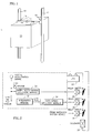
- FIG 1 is a perspective view of an elevator car 10 including an electronic braking system in accordance with the present invention.
- the car 10 travels on rails 12 as is known in the art.
- a controller 14 which detects over-acceleration and over-speed conditions and actuates braking assemblies 16.
- Figure 2 is a circuit diagram of a portion of the controller 14 which generates an output signal in the form of power to a solenoid 20 shown in both Figures 2 and 4 .
- Solenoid 20 is in the braking assembly 16 as described below with reference to Figures 4 and 5 .
- Solenoid 20 is powered by an uninterruptible power supply 22 through three safety relays 24, 26, and 28.
- Safety relays 24, 26, and 28 are normally open so that in the event of power failure, the safety relays 24, 26, and 28 will open disrupting power to the solenoid 20 and activating the braking assemblies 16. If any one of the safety relays 24, 26, or 28 is activated (e.g., opened), the current path to the solenoid 20 is broken. As described below with reference to Figures 4 and 5 , disconnecting power from solenoid 20 activates the braking assemblies 16. The conditions for activating the safety relays 24, 26, and 28 will now be discussed.
- a sensed acceleration signal ⁇ sensor is provided by an accelerometer 50 ( Figure 3 ) and provided to an over-acceleration detection module 30.
- the sensed acceleration signal is provided to the over-acceleration detection module 30 where the absolute value of the sensed acceleration is compared to an acceleration threshold. If the absolute value of the sensed acceleration exceeds the acceleration threshold, over-acceleration detection module 30 generates an over-acceleration signal which causes safety relay 24 to open and interrupt power to the solenoid 20 and activate the braking assemblies 16.
- the integration module 32 is designed to minimize the error term by using, for example, an operational amplifier integrator with a constant time such that: lim t ⁇ ⁇ ⁇ 0 t ⁇ ⁇ error t ⁇ dt ⁇ 0
- the integration module 32 provides the calculated car velocity to an over-speed detection module 34.
- the over-speed detection module 34 compares the absolute value of the calculated car velocity to a velocity threshold. If the absolute value of the calculated car velocity exceeds the velocity threshold, over-speed detection module 34 generates an over-speed signal which causes safety relay 26 to open and interrupt power to the solenoid 20 and activate the braking assemblies 16.
- the over-acceleration detection module 30 and over-speed detection module 34 are designed so as to not activate the braking assemblies when a passenger jumps in the car.
- FIG. 3 is a schematic diagram of another portion of the controller 14.
- Accelerometer 50 generates the sensed acceleration signal ⁇ sensor as described above.
- Accelerometer 50 may be a commercially available accelerometer such as a EuroSensor model 3021, a Sagem ASMI C30-HI or Analog Devices ADXL50.
- the circuit of Figure 3 includes circuitry for constantly determining whether the signal produced by the accelerometer 50 is accurate.
- a sinusoidal signal generator 52 produces a sinusoidal signal shown as ⁇ ' which is amplified by amplifier 54 and provided to a piezoelectric excitator 56.
- the accelerator 50 vibrates due to the vibration of the piezoelectric excitator 56.
- the output of the accelerometer 50 is a combination of the sensed acceleration ⁇ sensor and the piezoelectric vibration ⁇ '.
- the output of the accelerometer 50 and the output of amplifier 54 are provided to a synchronous detector 58.
- the synchronous detector separates the accelerometer ⁇ sensor and the accelerometer signal due to piezoelectric vibrations ⁇ '.
- the default module 60 detects the presence of the sinusoidal signal ⁇ ' in the accelerometer output. If the sinusoidal signal ⁇ ' is not present in the accelerometer output signal, then some part of the circuit (e.g. accelerometer 50) is not functioning properly and an activation signal is sent to safety relay 28 in Figure 2 . Activating safety relay 28 disrupts power to the solenoid 20 to activate braking assembly 16.
- the sensed accelerometer signal ⁇ sensor is provided to over-acceleration detection module 30 and integration module 32 as described above with reference to Figure 2 .
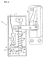
- FIG 4 is a side view of a braking assembly 16.
- the brake assembly includes an actuator 71 and a brake block 70.
- Brake block 70 may be similar to the safety brake disclosed in U.S. Patent 4,538,706 , the contents of which are incorporated herein by reference.
- the actuator 71 includes solenoid 20 (as shown in Figure 2 ) which, when powered, applies magnetic force F on a pivotal, L-shaped trigger 72.
- Trigger 72 includes a first arm 73 upon which the solenoid applies magnetic force and a second arm 75 substantially perpendicular to first arm 73. The force from solenoid 20 rotates the trigger 72 counter-clockwise and forces the trigger against a dog 74.
- Dog 74 is pivotally mounted on a pin 76 and has a first end 78 contacting a lip 80 on trigger 72 and a second end 82 engaging a lip 84 on rod 86.
- Rod 86 is biased upwards by a spring 88 compressed between a mounting plate 90 and a shoulder 92 on rod 86.
- a distal end of rod 86 is rotatably connected to a disengaging lever 94.
- An end of the disengaging lever 94 is positioned within a conventional brake block 70 and includes a jamming roller 96.
- the other end of disengaging lever 94 is pivotally connected at pin 100.
- the trigger 72, dog 74, rod 86 and disengaging lever 94 form a brake linkage for moving the jamming roller 96. It is understood that other mechanical interconnections may be used to form the brake linkage and the invention is not limited to the exemplary embodiment in Figure 4 .
- a bar 17 may be connected to the brake linkage (e.g. at disengaging lever 94) to move another jamming roller in another brake block 70 upon disrupting power to solenoid 20. Accordingly, only one actuator is needed for two brake blocks 70. Positioned above the rod 86 is a switch 98 which can disrupt power to the elevator hoist. In the condition shown in Figure 4 , the hoist is powered. The solenoid 20 is also receiving power thereby maintaining spring 88 in a compressed state through trigger 72, dog 74 and rod 86.
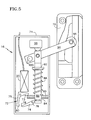
- Figure 5 shows the condition of the brake assembly upon detection of an over-speed condition, an over-acceleration condition or a defect in the controller.
- any of these conditions activates one of solenoids 24, 26 or 28 and disrupts power to solenoid 20.
- This allows trigger 72 to rotate freely and releases the dog 74.
- dog 74 is released from trigger 72, rod 86 is driven upwards by compressed spring 88.
- Disengage lever 94 is rotated counterclockwise forcing jamming roller 96 upwards into brake block 70 wedging the roller 96 against rail 12 and stopping movement of elevator car 10.
- switch 98 is contacted by the end of rod 86 so as to disrupt power to the elevator hoist.
- the invention activates the braking assembly upon detection of one of an over-acceleration event, an over-speed event or a failure in the controller circuitry. Operation of the braking system when the elevator cable breaks (i.e. an over-acceleration event) will now be described with reference to Figures 6 and 7.
- Figure 6 depicts graphs of the elevator car acceleration and velocity versus time when the car is traveling downward. The elevator car is traveling downward at a constant speed of V nominal and with an acceleration of 0. At time t 1 the elevator car cable breaks causing the acceleration to immediately become -1G. This causes the absolute value of the car acceleration to exceed Y nominal and the over-acceleration detection module 30 sends a signal to safety relay 24 to disrupt power to solenoid 20.
- the velocity of the car upon activation of the brake system is approximately V nominal in the downward direction. Because the elevator car is traveling downward, the brake block 70 engages rail 12 almost instantaneously.
- Figure 6 also depicts activation of the brake system as performed by the prior art system.
- the conventional emergency braking system would not detect the cable breakage until the car velocity exceeded a threshold of 115% of the nominal velocity.
- the conventional system would not detect the cable break and activate the emergency brake until time t 2 .
- the invention provides an earlier or anticipated activation of the emergency brake. Earlier activation of the emergency brake reduces the amount of kinetic energy that must be absorbed to stop the elevator car.
- Figure 7 depicts graphs of the elevator car acceleration and velocity versus time when the car is traveling upwards.
- the elevator car is traveling upwards at a constant speed of V ominal and with an acceleration of 0.
- the elevator car cable breaks causing the acceleration to immediately become -1G.
- This causes the absolute value of the car acceleration to exceed Y nominal and the over-acceleration detection module 30 sends a signal to safety relay 24 to disrupt power to solenoid 20.
- this activates the braking assemblies 16 to prevent the elevator car 10 from descending.
- activation of the braking assemblies does not immediately stop motion of the car.
- the brake block 70 is designed to restrict motion in the downward direction as is known in the art.
- the car will continue traveling upward due to its inertia until the car is speed is zero or slightly negative (downward).
- the brake block 70 engages rail 12 to prevent descent of the elevator car.
- the car is allowed to decelerate to a speed of approximately zero at which time the brake block 70 engages rail 12.
- the plot of velocity V car versus time in Figure 7 indicates that the car stops at time t 2 with a velocity of approximately 0 with the present invention.
- Figure 7 also depicts activation of the brake system as performed by the prior art system.
- the conventional emergency braking system would not detect the cable breakage until the car velocity exceeded a threshold of 115% of the nominal velocity.
- the conventional system would not detect the cable break and activate the emergency brake until time t 3 .
- the invention provides an earlier or anticipated activation of the emergency brake. Earlier activation of the emergency brake reduces the deceleration experienced by passengers in the elevator car.
- the braking system of the present invention provides earlier activation of the emergency braking system as compared to the conventional braking system. This reduces the amount of deceleration that the passengers must endure in an emergency braking situation.
- the invention provides an elevator safety system that is reliable and easily assembled. The over-acceleration and over-speed conditions can be adjusted electronically which makes the system applicable to a variety of cars.
Landscapes
- Maintenance And Inspection Apparatuses For Elevators (AREA)
- Elevator Control (AREA)
Applications Claiming Priority (2)
| Application Number | Priority Date | Filing Date | Title |
|---|---|---|---|
| US09/219,957 US6173813B1 (en) | 1998-12-23 | 1998-12-23 | Electronic control for an elevator braking system |
| EP99951603A EP1140688B1 (de) | 1998-12-23 | 1999-09-27 | Elektronisches sicherheitssystem für aufzug |
Related Parent Applications (2)
| Application Number | Title | Priority Date | Filing Date |
|---|---|---|---|
| EP99951603.2 Division | 1999-09-27 | ||
| EP99951603A Division EP1140688B1 (de) | 1998-12-23 | 1999-09-27 | Elektronisches sicherheitssystem für aufzug |
Publications (3)
| Publication Number | Publication Date |
|---|---|
| EP2108609A2 true EP2108609A2 (de) | 2009-10-14 |
| EP2108609A3 EP2108609A3 (de) | 2011-07-13 |
| EP2108609B1 EP2108609B1 (de) | 2013-06-12 |
Family
ID=22821430
Family Applications (2)
| Application Number | Title | Priority Date | Filing Date |
|---|---|---|---|
| EP09006026.0A Expired - Lifetime EP2108609B1 (de) | 1998-12-23 | 1999-09-27 | Elektronisches Sicherheitssystem für einen Fahrstuhl |
| EP99951603A Expired - Lifetime EP1140688B1 (de) | 1998-12-23 | 1999-09-27 | Elektronisches sicherheitssystem für aufzug |
Family Applications After (1)
| Application Number | Title | Priority Date | Filing Date |
|---|---|---|---|
| EP99951603A Expired - Lifetime EP1140688B1 (de) | 1998-12-23 | 1999-09-27 | Elektronisches sicherheitssystem für aufzug |
Country Status (8)
| Country | Link |
|---|---|
| US (1) | US6173813B1 (de) |
| EP (2) | EP2108609B1 (de) |
| JP (1) | JP2002533281A (de) |
| KR (1) | KR100617420B1 (de) |
| CN (1) | CN100341761C (de) |
| DE (1) | DE69941726D1 (de) |
| ES (2) | ES2419654T3 (de) |
| WO (1) | WO2000039016A1 (de) |
Cited By (2)
| Publication number | Priority date | Publication date | Assignee | Title |
|---|---|---|---|---|
| CN103648953A (zh) * | 2011-09-30 | 2014-03-19 | 因温特奥股份公司 | 具有电动机械致动装置的制动装置 |
| WO2014067814A1 (de) * | 2012-10-30 | 2014-05-08 | Inventio Ag | Bewegungs-überwachungssystem einer aufzugsanlage |
Families Citing this family (81)
| Publication number | Priority date | Publication date | Assignee | Title |
|---|---|---|---|---|
| HU230198B1 (hu) | 2000-11-23 | 2015-10-28 | Bavarian Nordic A/S | Módosított Vacciniavírus Ankara-variáns |
| ES2204222B1 (es) * | 2001-03-28 | 2005-08-01 | Raul Broch Coronado | Detector electronico y medios complementarios de actuacion sobre paracaidas de ascensores. |
| JP4987213B2 (ja) * | 2001-06-29 | 2012-07-25 | 三菱電機株式会社 | エレベータの非常ブレーキ装置 |
| KR100411150B1 (ko) * | 2001-07-07 | 2003-12-18 | 덕 규 김 | 엘리베이터용 로프 제동장치 |
| EP1400476B1 (de) * | 2002-09-23 | 2009-10-21 | Inventio Ag | Fangvorrichtung für Aufzüge |
| JP2004262652A (ja) * | 2002-09-23 | 2004-09-24 | Inventio Ag | エレベータ用の安全装置 |
| CN1720189A (zh) * | 2003-02-25 | 2006-01-11 | 三菱电机株式会社 | 电梯用调速器 |
| WO2004083090A1 (ja) * | 2003-03-18 | 2004-09-30 | Mitsubishi Denki Kabushiki Kaisha | エレベータの非常止め装置 |
| US7073632B2 (en) * | 2003-05-27 | 2006-07-11 | Invento Ag | Safety system for restraining movement of elevator car when car doors are open |
| US7097003B2 (en) * | 2003-07-21 | 2006-08-29 | The Peelle Company Ltd. | Elevator landing door broken chain safety device |
| PT1719729E (pt) * | 2004-02-26 | 2011-06-29 | Mitsubishi Electric Corp | Dispositivo de segurança de elevador |
| CN100453440C (zh) * | 2004-03-29 | 2009-01-21 | 三菱电机株式会社 | 致动器的驱动方法及致动器的驱动电路 |
| CA2543381C (en) | 2004-03-30 | 2009-06-23 | Mitsubishi Denki Kabushiki Kaisha | Elevator control apparatus |
| WO2005105651A1 (ja) * | 2004-04-30 | 2005-11-10 | Mitsubishi Denki Kabushiki Kaisha | エレベータ装置 |
| EP1749784B1 (de) * | 2004-05-25 | 2012-01-18 | Mitsubishi Denki Kabushiki Kaisha | Nothaltvorrichtung für aufzug |
| CN102173357B (zh) * | 2004-05-31 | 2013-05-15 | 三菱电机株式会社 | 电梯装置 |
| CN102173358B (zh) * | 2004-05-31 | 2015-02-18 | 三菱电机株式会社 | 电梯装置 |
| DE102004037486B4 (de) * | 2004-07-27 | 2006-08-10 | ThyssenKrupp Aufzüge GmbH | Signalband und System zum Bestimmen eines Bewegungszustandes eines bewegten Körpers sowie diese verwendende Vorrichtung zur Geschwindigkeitsbegrenzung des bewegten Körpers, insbesondere eines Aufzugfahrkorbes |
| FI20041044L (fi) * | 2004-07-30 | 2006-02-08 | Kone Corp | Hissi |
| JP4680262B2 (ja) * | 2004-12-03 | 2011-05-11 | オーチス エレベータ カンパニー | エレベータシステムで使用する安全装置 |
| AT501415B1 (de) * | 2005-01-21 | 2009-01-15 | Wittur Gmbh | Brems- bzw. fangeinrichtung für eine aufzugskabine |
| BRPI0601926B1 (pt) | 2005-06-17 | 2018-06-12 | Inventio Aktiengesellschaft | Dispositivo de pára-quedas do freio |
| KR100785179B1 (ko) * | 2005-08-25 | 2007-12-11 | 미쓰비시덴키 가부시키가이샤 | 엘리베이터용 조속기 |
| KR100938272B1 (ko) * | 2005-09-09 | 2010-01-22 | 오티스 엘리베이터 컴파니 | 엘리베이터들의 카 안전 디바이스를 위한 전기 안전 스위치리세팅 디바이스 |
| KR100720225B1 (ko) * | 2005-11-29 | 2007-05-23 | 미쓰비시덴키 가부시키가이샤 | 액츄에이터의 구동 방법, 및 액츄에이터의 구동 회로 |
| CN101360675B (zh) * | 2006-05-16 | 2011-04-27 | 三菱电机株式会社 | 电梯控制装置 |
| DE102006062754A1 (de) * | 2006-09-19 | 2008-04-03 | Wittur Ag | Bremsfangeinrichtung |
| CN101522554B (zh) * | 2006-10-18 | 2011-11-23 | 三菱电机株式会社 | 电梯限速装置以及电梯装置 |
| CN101535163B (zh) * | 2006-11-08 | 2011-09-28 | 奥蒂斯电梯公司 | 电梯制动装置 |
| DE502007007014D1 (de) † | 2007-11-12 | 2011-06-01 | Thyssenkrupp Elevator Ag | Bremsvorrichtung zum Bremsen eines Fahrkorbs |
| US8585158B2 (en) * | 2008-06-17 | 2013-11-19 | Otis Elevator Company | Safe control of a brake using low power control devices |
| CN102036898B (zh) * | 2008-06-27 | 2013-05-01 | 三菱电机株式会社 | 电梯装置及其运转方法 |
| WO2010098747A1 (en) * | 2009-02-25 | 2010-09-02 | Otis Elevator Company | Elevator safety device |
| CN102348625B (zh) * | 2009-03-16 | 2015-08-26 | 奥的斯电梯公司 | 过加速和过速检测与处理系统 |
| ES2614438T3 (es) * | 2009-03-16 | 2017-05-31 | Otis Elevator Company | Activador electromagnético de seguridad |
| BRPI0924457A2 (pt) * | 2009-03-16 | 2016-02-16 | Otis Elevator Co | sistema de segurança de elevador, e, elevador |
| EP2636626B1 (de) * | 2010-11-01 | 2018-03-21 | Mitsubishi Electric Corporation | Aufzugsvorrichtung |
| PH12013501109A1 (en) | 2010-12-17 | 2017-06-09 | Inventio Ag | Arrangement for actuating and restoring an intercepting apparatus |
| PH12013501088A1 (en) * | 2010-12-17 | 2013-07-08 | Inventio Ag | Lift installation comprising car and counterweight |
| JP5841173B2 (ja) | 2011-01-13 | 2016-01-13 | オーチス エレベータ カンパニーOtis Elevator Company | 加速度計を用いて位置を決定する装置および方法 |
| KR20130122663A (ko) * | 2011-04-01 | 2013-11-07 | 미쓰비시덴키 가부시키가이샤 | 엘리베이터 장치 |
| EP2760776B1 (de) | 2011-09-30 | 2015-06-03 | Inventio AG | Bremseinrichtung mit elektromechanischer betätigung |
| CN103130054A (zh) * | 2011-11-25 | 2013-06-05 | 深圳市一兆科技发展有限公司 | 一种获取轿厢运行速度的方法及相关装置 |
| JP5816102B2 (ja) * | 2012-01-12 | 2015-11-18 | 株式会社日立製作所 | 電子安全エレベータ |
| HUE027471T2 (en) * | 2012-01-25 | 2016-09-28 | Inventio Ag | Procedure and control device for monitoring the progress of a lift cabin |
| PL2828188T3 (pl) * | 2012-03-20 | 2017-10-31 | Inventio Ag | Urządzenie chwytające w instalacji dźwigowej |
| LU92027B1 (en) * | 2012-06-21 | 2013-12-23 | Khalil Mahmoud Abu Al-Rubb | Lift safety mechanism |
| DK2909122T3 (da) | 2012-10-18 | 2018-08-20 | Inventio Ag | Sikkerhedsindretning til en elevator |
| ES2622333T3 (es) * | 2012-11-13 | 2017-07-06 | Inventio Ag | Ascensor con un freno de seguridad |
| ES2483816B1 (es) * | 2013-02-07 | 2015-12-18 | S.A. Sistel | Sistema de control de posicionamiento, de limitación de velocidad y de movimientos incontrolados de cabina, o contrapeso, de un ascensor. |
| ES2896407T3 (es) * | 2013-08-08 | 2022-02-24 | Kone Corp | Procedimiento para controlar un ascensor y un ascensor |
| US9981826B2 (en) | 2013-09-11 | 2018-05-29 | Otis Elevator Company | Braking device for braking a hoisted object relative to a guide member |
| CN106458511B (zh) * | 2014-06-12 | 2019-04-12 | 奥的斯电梯公司 | 用于悬挂结构的制动系统重置机构 |
| WO2015191696A1 (en) * | 2014-06-12 | 2015-12-17 | Otis Elevator Company | Brake member actuation mechanism |
| CN107567423B (zh) * | 2015-03-20 | 2020-02-18 | 奥的斯电梯公司 | 电梯测试布置 |
| US9988240B2 (en) * | 2015-03-24 | 2018-06-05 | Thyssenkrupp Elevator Ag | Elevator with master controller |
| US11066274B2 (en) | 2015-06-30 | 2021-07-20 | Otis Elevator Company | Electromagnetic safety trigger |
| US10654686B2 (en) | 2015-06-30 | 2020-05-19 | Otis Elevator Company | Electromagnetic safety trigger |
| WO2017023926A1 (en) | 2015-08-04 | 2017-02-09 | Otis Elevator Company | Device and method for actuating an elevator safety brake |
| DE112015007155T5 (de) * | 2015-11-26 | 2018-08-09 | Mitsubishi Electric Corporation | Notfall-stoppvorrichtung für eine aufzugskabine |
| CN105975776A (zh) * | 2016-05-06 | 2016-09-28 | 深圳市安智车米汽车信息化有限公司 | 计算加速度积分以及判断汽车紧急制动的方法及装置 |
| EP3459890B1 (de) * | 2017-09-20 | 2024-04-03 | Otis Elevator Company | Überwachung des zustands von sicherheitsbremssystemen für aufzüge |
| JP2019156567A (ja) * | 2018-03-13 | 2019-09-19 | 株式会社日立製作所 | 非常止め装置及びエレベーター |
| US10336551B1 (en) * | 2018-03-23 | 2019-07-02 | Honda Motor Co., Ltd. | Over-travel limiting system and method of use thereof |
| US11155444B2 (en) * | 2018-05-01 | 2021-10-26 | Otis Elevator Company | Elevator door interlock assembly |
| US11046557B2 (en) | 2018-05-01 | 2021-06-29 | Otis Elevator Company | Elevator door interlock assembly |
| US11040858B2 (en) | 2018-05-01 | 2021-06-22 | Otis Elevator Company | Elevator door interlock assembly |
| US11040852B2 (en) | 2018-05-01 | 2021-06-22 | Otis Elevator Company | Elevator car control to address abnormal passenger behavior |
| US11034548B2 (en) | 2018-05-01 | 2021-06-15 | Otis Elevator Company | Elevator door interlock assembly |
| US11078045B2 (en) * | 2018-05-15 | 2021-08-03 | Otis Elevator Company | Electronic safety actuator for lifting a safety wedge of an elevator |
| KR101947438B1 (ko) * | 2018-05-16 | 2019-02-13 | 주식회사 신금성엘리베이터 | 승강기 응급제동장치 |
| EP3617115B1 (de) * | 2018-08-31 | 2025-03-12 | KONE Corporation | Aufzugsystem |
| US10822200B2 (en) * | 2018-10-12 | 2020-11-03 | Otis Elevator Company | Elevator safety actuator systems |
| WO2020110316A1 (ja) * | 2018-11-30 | 2020-06-04 | 株式会社日立製作所 | 非常停止装置 |
| US12134543B2 (en) | 2018-12-21 | 2024-11-05 | Inventio Ag | Elevator system arrangement having an elevator brake device |
| CN110422715B (zh) * | 2019-08-02 | 2021-01-15 | 浙江新再灵科技股份有限公司 | 一种直梯蹦跳检测方法及检测系统 |
| US20220250872A1 (en) * | 2019-08-29 | 2022-08-11 | Dynatech, Dynamics & Technology, S.L. | Electromechanical activation of a unidirectional emergency stop device for a lift |
| US11912536B2 (en) | 2019-10-07 | 2024-02-27 | Dynatech, Dynamics & Technology, S.L. | Electromechanical drive by flexible transmission for the activation of lift safeties |
| DE202019105584U1 (de) * | 2019-10-10 | 2019-10-22 | Wittur Holding Gmbh | Auslöseeinheit zum Betätigen einer Aufzugbremsvorrichtung |
| US11760604B1 (en) | 2022-05-27 | 2023-09-19 | Otis Elevator Company | Versatile elevator door interlock assembly |
| WO2024094398A1 (de) | 2022-11-04 | 2024-05-10 | Inventio Ag | Aktuierbares bauelement zur aktivierung oder deaktivierung einer baueinheit einer personentransportanlage sowie verriegelung für eine aufzugtür und fangvorrichtung für einen aufzugfahrkorb |
Citations (1)
| Publication number | Priority date | Publication date | Assignee | Title |
|---|---|---|---|---|
| US4538706A (en) | 1983-03-21 | 1985-09-03 | Otis Elevator Company | Progressive safety |
Family Cites Families (30)
| Publication number | Priority date | Publication date | Assignee | Title |
|---|---|---|---|---|
| US3584706A (en) * | 1968-10-10 | 1971-06-15 | Reliance Electric Co | Safties for elevator hoist motor control having high gain negative feedback loop |
| US4457404A (en) | 1982-05-26 | 1984-07-03 | Westinghouse Electric Corp. | Elevator system |
| US4662481A (en) | 1986-03-14 | 1987-05-05 | Westinghouse Electric Corp. | Elevator system |
| FI884745A7 (fi) | 1988-10-14 | 1990-04-15 | Kone Oy | Foerfarande foer styrning av en hiss' noedbroms samt en noedbroms. |
| JPH03124688A (ja) | 1989-03-27 | 1991-05-28 | Hitachi Ltd | 巻上機及びそれを用いたエレベーター装置 |
| JPH0466491A (ja) | 1990-07-09 | 1992-03-02 | Mitsubishi Electric Corp | ロープレスリニアモータエレベーター |
| US5065845A (en) | 1990-09-13 | 1991-11-19 | Pearson David B | Speed governor safety device for stopping an elevator car |
| US5052523A (en) | 1991-02-14 | 1991-10-01 | Otis Elevator Company | Elevator car-mounted govenor system |
| JPH05273226A (ja) * | 1991-03-25 | 1993-10-22 | Matsushita Electric Ind Co Ltd | 衝撃検出装置 |
| JPH04365771A (ja) | 1991-06-13 | 1992-12-17 | Toshiba Corp | エレベータ |
| ATE158560T1 (de) | 1991-11-18 | 1997-10-15 | Inventio Ag | Vorrichtung zum auslösen von sicherheitseinrichtungen |
| JP2646049B2 (ja) | 1991-11-27 | 1997-08-25 | 三菱電機株式会社 | エレベーター調速機 |
| JP2773518B2 (ja) * | 1992-02-28 | 1998-07-09 | 松下電器産業株式会社 | 加速度検出方法及び装置 |
| JP2878893B2 (ja) | 1992-03-18 | 1999-04-05 | 株式会社東芝 | 自走式エレベータ |
| JP3090809B2 (ja) | 1993-03-05 | 2000-09-25 | 株式会社東芝 | 自走式エレベータ |
| JPH072452A (ja) | 1993-06-15 | 1995-01-06 | Mitsubishi Electric Corp | リニアモータ駆動エレベーターのブレーキ制御装置 |
| EP0640552B1 (de) | 1993-08-24 | 1998-09-09 | Garaventa Holding Ag | Fang- und Blockiereinrichtung für einen auf Laufschienen geführten Laufwagen eines Schräg- oder Senkrechtaufzugs |
| ATE175946T1 (de) | 1993-10-18 | 1999-02-15 | Inventio Ag | Bremssicherheitseinrichtung für eine aufzugskabine |
| FI94948C (fi) | 1994-01-05 | 1995-11-27 | Kone Oy | Laitteisto hissin nopeudenrajoittimessa |
| JP3124688B2 (ja) | 1994-09-30 | 2001-01-15 | キヤノン株式会社 | 超電導装置 |
| JPH08133631A (ja) * | 1994-11-02 | 1996-05-28 | Mitsubishi Denki Bill Techno Service Kk | 油圧エレベーターの休止装置 |
| CA2161291C (en) | 1994-11-18 | 2006-01-10 | Christian Arpagaus | Excess speed detector with multiple light barrier |
| JPH08198543A (ja) | 1995-01-24 | 1996-08-06 | Toshio Higuchi | 調速機付きエレベーター篭 |
| JP3390578B2 (ja) | 1995-07-26 | 2003-03-24 | 三菱電機株式会社 | エレベータ調速機 |
| JPH0967071A (ja) * | 1995-08-31 | 1997-03-11 | Hitachi Building Syst Co Ltd | エレベータの異常時運転装置 |
| US5900596A (en) | 1995-10-06 | 1999-05-04 | Inventio Ag | Hydraulic brake controller |
| JP3532349B2 (ja) | 1996-06-11 | 2004-05-31 | 三菱電機株式会社 | エレベータの安全装置 |
| EP0841282A1 (de) | 1996-11-11 | 1998-05-13 | Inventio Ag | Bremsauslösevorrichtung |
| FI105091B (fi) | 1997-01-30 | 2000-06-15 | Kone Corp | Johdejarru |
| JPH10324474A (ja) * | 1997-05-26 | 1998-12-08 | Mitsubishi Electric Corp | エレベーターの終端階減速装置 |
-
1998
- 1998-12-23 US US09/219,957 patent/US6173813B1/en not_active Expired - Lifetime
-
1999
- 1999-09-27 ES ES09006026T patent/ES2419654T3/es not_active Expired - Lifetime
- 1999-09-27 JP JP2000590936A patent/JP2002533281A/ja active Pending
- 1999-09-27 DE DE69941726T patent/DE69941726D1/de not_active Expired - Lifetime
- 1999-09-27 EP EP09006026.0A patent/EP2108609B1/de not_active Expired - Lifetime
- 1999-09-27 CN CNB998149934A patent/CN100341761C/zh not_active Expired - Lifetime
- 1999-09-27 ES ES99951603T patent/ES2335370T3/es not_active Expired - Lifetime
- 1999-09-27 KR KR1020017007757A patent/KR100617420B1/ko not_active Expired - Fee Related
- 1999-09-27 WO PCT/US1999/022298 patent/WO2000039016A1/en not_active Ceased
- 1999-09-27 EP EP99951603A patent/EP1140688B1/de not_active Expired - Lifetime
Patent Citations (1)
| Publication number | Priority date | Publication date | Assignee | Title |
|---|---|---|---|---|
| US4538706A (en) | 1983-03-21 | 1985-09-03 | Otis Elevator Company | Progressive safety |
Cited By (3)
| Publication number | Priority date | Publication date | Assignee | Title |
|---|---|---|---|---|
| CN103648953A (zh) * | 2011-09-30 | 2014-03-19 | 因温特奥股份公司 | 具有电动机械致动装置的制动装置 |
| WO2014067814A1 (de) * | 2012-10-30 | 2014-05-08 | Inventio Ag | Bewegungs-überwachungssystem einer aufzugsanlage |
| US9926170B2 (en) | 2012-10-30 | 2018-03-27 | Inventio Ag | Movement-monitoring system of an elevator installation |
Also Published As
| Publication number | Publication date |
|---|---|
| EP1140688B1 (de) | 2009-11-25 |
| WO2000039016A1 (en) | 2000-07-06 |
| ES2419654T3 (es) | 2013-08-21 |
| JP2002533281A (ja) | 2002-10-08 |
| ES2335370T3 (es) | 2010-03-25 |
| US6173813B1 (en) | 2001-01-16 |
| CN1331653A (zh) | 2002-01-16 |
| KR20010089655A (ko) | 2001-10-08 |
| CN100341761C (zh) | 2007-10-10 |
| KR100617420B1 (ko) | 2006-08-30 |
| EP2108609A3 (de) | 2011-07-13 |
| EP1140688A1 (de) | 2001-10-10 |
| EP2108609B1 (de) | 2013-06-12 |
| DE69941726D1 (de) | 2010-01-07 |
Similar Documents
| Publication | Publication Date | Title |
|---|---|---|
| EP2108609B1 (de) | Elektronisches Sicherheitssystem für einen Fahrstuhl | |
| US8631909B2 (en) | Electromagnetic safety trigger | |
| US8939262B2 (en) | Elevator over-acceleration and over-speed protection system | |
| US8827044B2 (en) | Over-acceleration and over-speed detection and processing system | |
| EP1604935B1 (de) | Aufzugsgerät und not-aus-vorrichtung für den aufzug | |
| US7614481B2 (en) | Elevator apparatus including a safety control portion that detects an abnormality | |
| EP1497214A1 (de) | Überdrehzahlreglervorrichtung für aufzugssystem | |
| EP1741659B1 (de) | Aufzugsvorrichtung | |
| US7819229B2 (en) | Elevator safety system | |
| HK1166772B (en) | Elevator over-acceleration and over-speed protection system | |
| HK1166771A (en) | Electromagnetic safety trigger | |
| HK1166771B (en) | Electromagnetic safety trigger |
Legal Events
| Date | Code | Title | Description |
|---|---|---|---|
| PUAI | Public reference made under article 153(3) epc to a published international application that has entered the european phase |
Free format text: ORIGINAL CODE: 0009012 |
|
| AC | Divisional application: reference to earlier application |
Ref document number: 1140688 Country of ref document: EP Kind code of ref document: P |
|
| AK | Designated contracting states |
Kind code of ref document: A2 Designated state(s): DE ES FR IT |
|
| RIN1 | Information on inventor provided before grant (corrected) |
Inventor name: REBILLARD, PASCAL Inventor name: SIRIGU, GERARD Inventor name: RAILLARD, VINCENT |
|
| PUAL | Search report despatched |
Free format text: ORIGINAL CODE: 0009013 |
|
| AK | Designated contracting states |
Kind code of ref document: A3 Designated state(s): DE ES FR IT |
|
| AX | Request for extension of the european patent |
Extension state: AL LT LV MK RO SI |
|
| RIC1 | Information provided on ipc code assigned before grant |
Ipc: B66B 5/22 20060101ALI20110609BHEP Ipc: B66B 5/06 20060101AFI20090903BHEP |
|
| 17P | Request for examination filed |
Effective date: 20120110 |
|
| RBV | Designated contracting states (corrected) |
Designated state(s): AT BE CH CY DE DK ES FI FR GB GR IE IT LI LU MC NL PT SE |
|
| RIC1 | Information provided on ipc code assigned before grant |
Ipc: B66B 5/06 20060101AFI20121116BHEP Ipc: B66B 5/22 20060101ALI20121116BHEP |
|
| GRAP | Despatch of communication of intention to grant a patent |
Free format text: ORIGINAL CODE: EPIDOSNIGR1 |
|
| RBV | Designated contracting states (corrected) |
Designated state(s): DE ES FR IT |
|
| GRAS | Grant fee paid |
Free format text: ORIGINAL CODE: EPIDOSNIGR3 |
|
| GRAA | (expected) grant |
Free format text: ORIGINAL CODE: 0009210 |
|
| AC | Divisional application: reference to earlier application |
Ref document number: 1140688 Country of ref document: EP Kind code of ref document: P |
|
| AK | Designated contracting states |
Kind code of ref document: B1 Designated state(s): DE ES FR IT |
|
| REG | Reference to a national code |
Ref country code: DE Ref legal event code: R096 Ref document number: 69944782 Country of ref document: DE Effective date: 20130801 |
|
| REG | Reference to a national code |
Ref country code: ES Ref legal event code: FG2A Ref document number: 2419654 Country of ref document: ES Kind code of ref document: T3 Effective date: 20130821 |
|
| PLBE | No opposition filed within time limit |
Free format text: ORIGINAL CODE: 0009261 |
|
| STAA | Information on the status of an ep patent application or granted ep patent |
Free format text: STATUS: NO OPPOSITION FILED WITHIN TIME LIMIT |
|
| 26N | No opposition filed |
Effective date: 20140313 |
|
| REG | Reference to a national code |
Ref country code: DE Ref legal event code: R097 Ref document number: 69944782 Country of ref document: DE Effective date: 20140313 |
|
| PGFP | Annual fee paid to national office [announced via postgrant information from national office to epo] |
Ref country code: IT Payment date: 20140923 Year of fee payment: 16 |
|
| PG25 | Lapsed in a contracting state [announced via postgrant information from national office to epo] |
Ref country code: IT Free format text: LAPSE BECAUSE OF NON-PAYMENT OF DUE FEES Effective date: 20150927 |
|
| REG | Reference to a national code |
Ref country code: FR Ref legal event code: PLFP Year of fee payment: 18 |
|
| REG | Reference to a national code |
Ref country code: DE Ref legal event code: R082 Ref document number: 69944782 Country of ref document: DE Representative=s name: SCHMITT-NILSON SCHRAUD WAIBEL WOHLFROM PATENTA, DE |
|
| REG | Reference to a national code |
Ref country code: FR Ref legal event code: PLFP Year of fee payment: 19 |
|
| REG | Reference to a national code |
Ref country code: FR Ref legal event code: PLFP Year of fee payment: 20 |
|
| PGFP | Annual fee paid to national office [announced via postgrant information from national office to epo] |
Ref country code: DE Payment date: 20180821 Year of fee payment: 20 Ref country code: FR Payment date: 20180822 Year of fee payment: 20 |
|
| PGFP | Annual fee paid to national office [announced via postgrant information from national office to epo] |
Ref country code: ES Payment date: 20181001 Year of fee payment: 20 |
|
| REG | Reference to a national code |
Ref country code: DE Ref legal event code: R071 Ref document number: 69944782 Country of ref document: DE |
|
| REG | Reference to a national code |
Ref country code: ES Ref legal event code: FD2A Effective date: 20201002 |
|
| PG25 | Lapsed in a contracting state [announced via postgrant information from national office to epo] |
Ref country code: ES Free format text: LAPSE BECAUSE OF EXPIRATION OF PROTECTION Effective date: 20190928 |