EP3617115B1 - Aufzugsystem - Google Patents
Aufzugsystem Download PDFInfo
- Publication number
- EP3617115B1 EP3617115B1 EP18191950.7A EP18191950A EP3617115B1 EP 3617115 B1 EP3617115 B1 EP 3617115B1 EP 18191950 A EP18191950 A EP 18191950A EP 3617115 B1 EP3617115 B1 EP 3617115B1
- Authority
- EP
- European Patent Office
- Prior art keywords
- safety
- elevator
- contact
- elevator car
- solenoid
- Prior art date
- Legal status (The legal status is an assumption and is not a legal conclusion. Google has not performed a legal analysis and makes no representation as to the accuracy of the status listed.)
- Active
Links
Images

Classifications
-
- B—PERFORMING OPERATIONS; TRANSPORTING
- B66—HOISTING; LIFTING; HAULING
- B66B—ELEVATORS; ESCALATORS OR MOVING WALKWAYS
- B66B5/00—Applications of checking, fault-correcting, or safety devices in elevators
- B66B5/02—Applications of checking, fault-correcting, or safety devices in elevators responsive to abnormal operating conditions
-
- B—PERFORMING OPERATIONS; TRANSPORTING
- B66—HOISTING; LIFTING; HAULING
- B66B—ELEVATORS; ESCALATORS OR MOVING WALKWAYS
- B66B13/00—Doors, gates, or other apparatus controlling access to, or exit from, cages or lift well landings
- B66B13/22—Operation of door or gate contacts
-
- B—PERFORMING OPERATIONS; TRANSPORTING
- B66—HOISTING; LIFTING; HAULING
- B66B—ELEVATORS; ESCALATORS OR MOVING WALKWAYS
- B66B5/00—Applications of checking, fault-correcting, or safety devices in elevators
- B66B5/02—Applications of checking, fault-correcting, or safety devices in elevators responsive to abnormal operating conditions
- B66B5/04—Applications of checking, fault-correcting, or safety devices in elevators responsive to abnormal operating conditions for detecting excessive speed
-
- B—PERFORMING OPERATIONS; TRANSPORTING
- B66—HOISTING; LIFTING; HAULING
- B66B—ELEVATORS; ESCALATORS OR MOVING WALKWAYS
- B66B1/00—Control systems of elevators in general
- B66B1/34—Details, e.g. call counting devices, data transmission from car to control system, devices giving information to the control system
- B66B1/3415—Control system configuration and the data transmission or communication within the control system
- B66B1/3423—Control system configuration, i.e. lay-out
-
- B—PERFORMING OPERATIONS; TRANSPORTING
- B66—HOISTING; LIFTING; HAULING
- B66B—ELEVATORS; ESCALATORS OR MOVING WALKWAYS
- B66B5/00—Applications of checking, fault-correcting, or safety devices in elevators
- B66B5/0006—Monitoring devices or performance analysers
- B66B5/0018—Devices monitoring the operating condition of the elevator system
- B66B5/0031—Devices monitoring the operating condition of the elevator system for safety reasons
-
- B—PERFORMING OPERATIONS; TRANSPORTING
- B66—HOISTING; LIFTING; HAULING
- B66B—ELEVATORS; ESCALATORS OR MOVING WALKWAYS
- B66B5/00—Applications of checking, fault-correcting, or safety devices in elevators
- B66B5/0043—Devices enhancing safety during maintenance
- B66B5/005—Safety of maintenance personnel
- B66B5/0056—Safety of maintenance personnel by preventing crushing
- B66B5/0062—Safety of maintenance personnel by preventing crushing by devices, being operable or not, mounted on the elevator car
-
- B—PERFORMING OPERATIONS; TRANSPORTING
- B66—HOISTING; LIFTING; HAULING
- B66B—ELEVATORS; ESCALATORS OR MOVING WALKWAYS
- B66B5/00—Applications of checking, fault-correcting, or safety devices in elevators
- B66B5/0043—Devices enhancing safety during maintenance
- B66B5/005—Safety of maintenance personnel
- B66B5/0056—Safety of maintenance personnel by preventing crushing
- B66B5/0068—Safety of maintenance personnel by preventing crushing by activating the safety brakes when the elevator car exceeds a certain upper or lower position in the elevator shaft
-
- B—PERFORMING OPERATIONS; TRANSPORTING
- B66—HOISTING; LIFTING; HAULING
- B66B—ELEVATORS; ESCALATORS OR MOVING WALKWAYS
- B66B5/00—Applications of checking, fault-correcting, or safety devices in elevators
- B66B5/0087—Devices facilitating maintenance, repair or inspection tasks
- B66B5/0093—Testing of safety devices
-
- B—PERFORMING OPERATIONS; TRANSPORTING
- B66—HOISTING; LIFTING; HAULING
- B66B—ELEVATORS; ESCALATORS OR MOVING WALKWAYS
- B66B5/00—Applications of checking, fault-correcting, or safety devices in elevators
- B66B5/02—Applications of checking, fault-correcting, or safety devices in elevators responsive to abnormal operating conditions
- B66B5/16—Braking or catch devices operating between cars, cages, or skips and fixed guide elements or surfaces in hoistway or well
Definitions
- Safety is an important factor in elevator systems. These systems may comprise a number of safety devices providing signals for a controlling unit, for example, a safety circuit board. The controlling unit then determines whether operation of an elevator car is possible.
- a serviceman may override the safety circuit intentionally or unintentionally.
- the safety circuit may also become short-circuited, for example, by dirt in shaft electronics or wear of a traveling cable, leaving safety measures in the shaft completely inoperable. This is a critical safety issue especially in elevators With elevator shafts having low/no headroom or pit, according to regulations there has to be a device limiting the elevator car travel, normally activated when the safety circuit is in the inspection mode. However, it may be possible that the device limiting the elevator car travel has also been short-circuited.
- US 2013/0118836 A1 discloses an elevator that includes an elevator cage, a drive arrangement, a first safety controller and a second safety controller.
- the first and the second safety controllers monitor a state of the elevator respectively by means of at least one first or second sensor and on detection of an unsafe state institute a measure in order to bring the elevator into a safe state.
- the first safety controller is arranged on the elevator cage and the second safety controller is arranged in the region of the drive arrangement.
- a solution is provided that enables stopping an elevator car even if all electrically controlled stopping devices have become non-operational.
- an elevator system comprising an elevator car configured to move in an elevator shaft; a main safety controller comprising a main safety output and a secondary safety output, wherein the main safety output is configured to control machinery brakes of the elevator car; and a secondary safety circuit connected to the secondary safety output and arranged in the elevator car and comprising at least one safety contact configured to control stopping means arranged in the elevator car.
- the secondary safety circuit is configured to control the stopping means to cause stopping of the elevator car.
- the stopping means comprises a solenoid, an engagement mechanism and a safety gear, wherein in response to triggering the at least one contact, the solenoid is configured to cause the engagement mechanism to move to a position enabling contact with a triggering device in the elevator shaft, the triggering device in turn causing activation of the safety gear.
- the main safety controller further comprises a first input connected to the solenoid, wherein the main safety controller is configured to test the operation of the solenoid by switching off the secondary safety output and determining whether feedback information is received from the solenoid at the first input.
- the main safety controller is configured to test the operation of the solenoid at each stop of the elevator car.
- the main safety controller is configured to test the operation of the solenoid when testing the operation of the machinery brakes of the elevator car.
- the at least one safety contact is associated with at least one balustrade contact.
- the main safety controller comprises a second input connected to the at least one balustrade contact, wherein the main safety controller is configured to receive a signal at the second input when the at least one balustrade contact is triggered.
- the at least one safety contact comprises an ascending car overspeed protection contact.
- the at least one safety contact comprises a safety light curtain configured to be triggered when detecting an obstacle under the elevator car.
- the at least one safety contact comprises at least one pressure sensor on the roof of the elevator car.
- a secondary safety circuit separate from a first safety circuit associated with machinery brakes of an elevator car is provided for securing a safety space when the roof of an elevator car or a shaft pit is occupied.
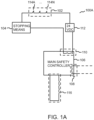
- FIG. 1A illustrates a block diagram of an elevator system 100A according to an aspect.
- the elevator system 100A comprises a main safety controller 106 configured to control safety operations of the elevator system 100A comprising at least one elevator car.
- the main safety controller 106 is configured to monitor a status of a first safety circuit 116, and if there are no issues with the first safety circuit 116, the main safety controller 106 controls via a main safety output 108 power supply to the machinery and/or machinery brakes of the elevator.
- the safety circuit 116 may comprise a plurality of switches that monitor the operation of various elements, such as car and landing doors, car position and overspeed governor, in the elevator system.
- the elevator system 100A comprises a secondary safety circuit 102.
- the secondary safety circuit 102 is connected to a secondary safety output 110 of the main safety controller 106 and arranged in the elevator car.
- a power source 112 may be provided to provide power to the secondary safety circuit 102.
- the secondary safety circuit 102 comprises at least one safety contact 114A...114N configured to control stopping means 104 arranged in the elevator car. In an example, regardless of the status of the main safety circuit 106 or the machinery brakes, the secondary safety circuit 102 is able to cause stopping of the elevator car. When the at least one safety contact 114A...114N is triggered, the secondary safety circuit 102 is configured to control the stopping means 104 to cause stopping of the elevator car.
- the at least one safety contact 114A...114N may comprise different types of elements.
- the at least one safety contact 114A...114N may be related to one or more balustrades arranged on the roof of the elevator car.
- the balustrade When the balustrade is moved from its resting position either upwards (as in setting it up) or downwards (as when a person is standing on a folded-down balustrade), this is detected, for example, by at least one switch arranged in connection with the balustrade.
- the safety contact associated with the balustrade is a normally closed (NC) contact
- the safety contact opens when the balustrade is deviated from its resting position and, thus, causes a state change in the secondary safety circuit 102.
- NC normally closed
- Another example of possible safety contacts 114A...114N comprises an ascending car overspeed protection (ACOP) contact associated with a specific speed limit.
- the safety contact may be a 115% normally closed safety contact. This means that when a specific speed limit of the elevator car is exceeded by 15%, the normally closed safety contact opens and causes a state change in the secondary safety circuit 102.
- Another example of possible safety contacts 114A...114N comprises a safety light curtain configured to be triggered when detecting an obstacle under the elevator car.
- the safety light curtain may be used to detect obstacles below the elevator car in the elevator shaft.
- Another example of possible safety contacts 114A...114N comprises at least one pressure sensor on the roof of the elevator car.
- a pressure mat may be arranged on the roof of the elevator car to detect any person present on the roof.
- the stopping means 104 comprises a solenoid, an engagement mechanism and a safety gear.
- the secondary safety circuit 102 is connected to the solenoid. Normally, when all the safety contacts 114A...114N of the secondary safety circuit 102 are in their normal state, i.e. in the normally closed state, electricity flows to the solenoid and its plunger is in a retracted position. When the state of one of the safety contacts 114A...114N changes, the electricity flow to the solenoid is interrupted. This causes the plunger to protrude and make contact with the engagement mechanism.
- the engagement mechanism in turn moves to a position that enables a contact with a triggering device located in the elevator shaft.
- the triggering device causes activation of the safety gear of the elevator car.
- the triggering device may be located close to the upper end of the elevator shaft.
- FIG. 1B illustrates a block diagram of an elevator system according to another aspect.
- the example illustrated in FIG. 1B is similar than was already illustrated in FIG. 1A , and already discussed elements are not discussed again, and reference is made to the description of FIG. 1A .
- the main safety controller 106 When the main safety controller 106 is configured to switch off the secondary safety output 110, the main safety controller 106 may stop controlling a normally open (NO) switch or switches of the secondary safety output 110. This in turn breaks the secondary safety circuit 102, and the electrical power supply to the solenoid is interrupted, as already discussed above.
- NO normally open
- the testing of the solenoid can be performed, for example, at each stop of the elevator car. This ensures continuous monitoring of the solenoid and if the solenoid is faulty, this can be detected quickly.
- the testing of the solenoid is performed simultaneously when testing the operation of the machinery brakes of the elevator car.
- the machinery brake testing and thus also the solenoid testing may be performed, for example, once in every 11 hours. It is evident that the testing period of the solenoid may also be any other time period, for example, one day.
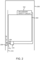
- FIG. 2 illustrates an elevator car 202 in an elevator shaft 200 according to an embodiment.
- the secondary safety circuit 102 has been arranged in the elevator car 202.
- the operation of the secondary safety circuit 102 has been discussed in more detail in relation to FIGS. 1A and 1B , and therefore, this discussion is not repeated here, and reference is made to the description of FIGS. 1A and 1B .
- the solenoid 210 is connected to the secondary safety circuit 102.
- FIG. 2 discloses a simplified illustration of how the solenoid 210 is behaving when the electricity flow to the solenoid 210 is interrupted in response to triggering at least one safety contact of the secondary safety circuit 102.
- This causes an engagement mechanism 204, for example, a plunger to protrude.
- the engagement mechanism 204 i.e. the plunger, then in turn moves to a position that will contact the triggering device 206 located in the elevator shaft 200 when the elevator car 202 moves upwards in the elevator shaft 200.
- the triggering device 206 prevents the engagement mechanism 204 to move freely with the elevator car 202.
- FIG. 2 illustrates one exemplary form for the triggering device 206, it is evident that the triggering device 206 may take any other appropriate form that is able to cooperate with the plunger 208.
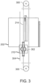
- FIG. 3 illustrates an elevator car 202 in an elevator shaft according to another embodiment.
- FIG. 3 discloses a different view of the arrangement illustrated in FIG. 2 .
- the elevator car 202 is configured to move in the elevator shaft. It is evident that FIG. 3 may not necessarily disclose all elements present in the elevator shaft.
- the speed limiting rope 214 moves together with the elevator car 202.
- Diverting pulleys 300 may be used at each end of the elevator shaft in connection with the speed limiting rope 214.
- an engagement mechanism 204 for example, a plunger to protrude.
- the engagement mechanism 204 i.e. the plunger, then in turn moves to a position that will contact the triggering device 206 located in the elevator shaft 200 when the elevator car 202 moves upwards in the elevator shaft 200.
- the triggering device 206 prevents the engagement mechanism 204 to move freely with the elevator car 202. This in turn prevents the speed limiting rope 214 to move freely with the elevator car 202, causing a safety gear 302 of the elevator car 202 to tighten to a guide rail 304 in the elevator shaft, eventually stopping the elevator car 202.
- One or more of the above embodiments may provide at least one of the following benefits.
- the disclosed solution provides a mechanical solution for stopping the elevator car
- the solution works even if the elevator car approaches an end of the elevator shaft during a power failure.
- the first safety circuit is short-circuited, this does not have any effect on the operation of the secondary safety circuit.
- the secondary safety circuit is short-circuited, this will be realized when testing the solenoid.
- Example embodiments may be implemented in software, hardware, application logic or a combination of software, hardware and application logic.
- the example embodiments can store information relating to various methods described herein. This information can be stored in one or more memories, such as a hard disk, optical disk, magneto-optical disk, RAM, and the like.
- One or more databases can store the information used to implement the example embodiments. The databases can be organized using data structures (e.g., records, tables, arrays, fields, graphs, trees, lists, and the like) included in one or more memories or storage devices listed herein.
- All or a portion of the example embodiments can be conveniently implemented using one or more general purpose processors, microprocessors, digital signal processors, micro-controllers, and the like, programmed according to the teachings of the example embodiments, as will be appreciated by those skilled in the computer and/or software art(s).
- the examples can include software for controlling the components of the example embodiments, for driving the components of the example embodiments, for enabling the components of the example embodiments to interact with a human user, and the like.
- Such computer readable media further can include a computer program for performing all or a portion (if processing is distributed) of the processing performed in implementing the example embodiments.
- a "computer-readable medium” may be any media or means that can contain, store, communicate, propagate or transport the instructions for use by or in connection with an instruction execution system, apparatus, or device, such as a computer.
- a computer-readable medium may include a computer-readable storage medium that may be any media or means that can contain or store the instructions for use by or in connection with an instruction execution system, apparatus, or device, such as a computer.
- a computer readable medium can include any suitable medium that participates in providing instructions to a processor for execution. Such a medium can take many forms, including but not limited to, non-volatile media, volatile media, transmission media, and the like.
Landscapes
- Engineering & Computer Science (AREA)
- Automation & Control Theory (AREA)
- Mechanical Engineering (AREA)
- Computer Networks & Wireless Communication (AREA)
- Maintenance And Inspection Apparatuses For Elevators (AREA)
- Elevator Control (AREA)
Claims (8)
- Aufzugsystem (100A, 100B), umfassend:eine Aufzugskabine (202), die dazu konfiguriert ist, sich in einem Aufzugsschacht (200) zu bewegen;einen ersten Sicherheitskreis (116);eine Hauptsicherheitssteuerung (106), die eine Hauptsicherheitsausgabe (108) und eine sekundäre Sicherheitsausgabe (110) umfasst, wobei die Hauptsicherheitsausgabe (108) dazu konfiguriert ist, Maschinenbremsen der Aufzugskabine (202) basierend auf dem ersten Sicherheitskreis (116) zu steuern; undeinen sekundären Sicherheitskreis (102), der mit der sekundären Sicherheitsausgabe (110) verbunden ist und in der Aufzugskabine (202) angeordnet ist und mindestens einen Sicherheitskontakt (114A...114N) umfasst, der dazu konfiguriert ist, Stoppmittel (104) zu steuern, die in der Aufzugskabine (202) angeordnet sind;wobei wenn der mindestens eine Sicherheitskontakt (114A...114N) ausgelöst wird, der sekundäre Sicherheitskreis (102) dazu konfiguriert ist, die Stoppmittel (104) zu steuern, um ein Stoppen der Aufzugskabine (202) zu verursachen, dadurch gekennzeichnet, dassdie Stoppmittel (104) einen Solenoid (210), einen Eingriffsmechanismus (204) und eine Fangvorrichtung umfassen, wobei in Antwort auf das Auslösen des mindestens einen Kontakts (114A...114N), der Solenoid (210) so konfiguriert ist, dass er den Eingriffsmechanismus (204) veranlasst, sich in eine Position zu bewegen, die den Kontakt mit einer Auslösevorrichtung (206) im Aufzugsschacht (200) erlaubt, wobei die Auslösevorrichtung (206) wiederum die Aktivierung der Fangvorrichtung verursacht, undwobei die Hauptsicherheitssteuerung (106) einen ersten Eingang (118) umfasst, der mit dem Solenoid (210) verbunden ist, wobei die Hauptsicherheitssteuerung (106) dazu konfiguriert ist, den Betrieb des Solenoids (210) zu testen, indem die sekundäre Sicherheitsausgabe (110) ausgeschaltet wird und bestimmt wird, ob Rückkopplungsinformationen von dem Solenoid an dem ersten Eingang (118) empfangen werden.
- Aufzugssystem (100A, 100B) nach Anspruch 1, wobei die Hauptsicherheitssteuerung (106) dazu konfiguriert ist, den Betrieb des Solenoids (210) an jedem Halt der Aufzugskabine (202) zu testen.
- Aufzugssystem (100A, 100B) nach Anspruch 1, wobei die Hauptsicherheitssteuerung (106) dazu konfiguriert ist, den Betrieb des Solenoids (210) zu testen, wenn der Betrieb der Maschinenbremsen der Aufzugskabine (202) getestet wird.
- Aufzugssystem (100A, 100B) nach einem der Ansprüche 1-3, wobei der mindestens eine Sicherheitskontakt (114A... 114N) mit mindestens einem Balustradenkontakt assoziiert ist.
- Aufzugssystem (100A, 100B) nach Anspruch 4, wobei die Hauptsicherheitssteuerung (106) einen zweiten Eingang (120) umfasst, der mit dem mindestens einen Balustradenkontakt verbunden ist, wobei die Hauptsicherheitssteuerung (106) dazu konfiguriert ist, ein Signal an dem zweiten Eingang (120) zu empfangen, wenn der mindestens eine Balustradenkontakt ausgelöst wird.
- Aufzugssystem (100A, 100B) nach einem der Ansprüche 1-5, wobei der mindestens eine Sicherheitskontakt (114A...114N) einen Kontakt zum Schutz vor Übergeschwindigkeit der aufwärtsfahrenden Kabine umfasst.
- Aufzugssystem (100A, 100B) nach einem der Ansprüche 1-6, wobei der mindestens eine Sicherheitskontakt (114A... 114N) einen Sicherheitslichtvorhang umfasst, der so konfiguriert ist, dass er ausgelöst wird, wenn ein Hindernis unter der Aufzugskabine (102) detektiert wird.
- Aufzugssystem (100A, 100B) nach einem der Ansprüche 1-7, wobei der mindestens eine Sicherheitskontakt (114A...114N) mindestens einen Drucksensor auf dem Dach der Aufzugskabine (102) umfasst.
Priority Applications (4)
| Application Number | Priority Date | Filing Date | Title |
|---|---|---|---|
| EP18191950.7A EP3617115B1 (de) | 2018-08-31 | 2018-08-31 | Aufzugsystem |
| FIEP18191950.7T FI3617115T3 (fi) | 2018-08-31 | 2018-08-31 | Hissijärjestelmä |
| US16/458,837 US11718503B2 (en) | 2018-08-31 | 2019-07-01 | Elevator system |
| CN201910689626.0A CN110872040B (zh) | 2018-08-31 | 2019-07-29 | 电梯系统 |
Applications Claiming Priority (1)
| Application Number | Priority Date | Filing Date | Title |
|---|---|---|---|
| EP18191950.7A EP3617115B1 (de) | 2018-08-31 | 2018-08-31 | Aufzugsystem |
Publications (2)
| Publication Number | Publication Date |
|---|---|
| EP3617115A1 EP3617115A1 (de) | 2020-03-04 |
| EP3617115B1 true EP3617115B1 (de) | 2025-03-12 |
Family
ID=63452519
Family Applications (1)
| Application Number | Title | Priority Date | Filing Date |
|---|---|---|---|
| EP18191950.7A Active EP3617115B1 (de) | 2018-08-31 | 2018-08-31 | Aufzugsystem |
Country Status (4)
| Country | Link |
|---|---|
| US (1) | US11718503B2 (de) |
| EP (1) | EP3617115B1 (de) |
| CN (1) | CN110872040B (de) |
| FI (1) | FI3617115T3 (de) |
Families Citing this family (1)
| Publication number | Priority date | Publication date | Assignee | Title |
|---|---|---|---|---|
| WO2025061414A1 (en) * | 2023-09-22 | 2025-03-27 | Inventio Ag | A device for operating a safety mechanism of an elevator unit |
Family Cites Families (12)
| Publication number | Priority date | Publication date | Assignee | Title |
|---|---|---|---|---|
| US5476157A (en) * | 1994-06-03 | 1995-12-19 | Todaro; Sam S. | Elevator control system with elevator hoistway operation monitoring system and method |
| US6173813B1 (en) * | 1998-12-23 | 2001-01-16 | Otis Elevator Company | Electronic control for an elevator braking system |
| WO2004096690A1 (de) * | 2003-04-30 | 2004-11-11 | Thyssenkrupp Elevator Ag | Aufzuganlage sowie verfahren zum steuern einer aufzuganlage |
| CN101072723B (zh) * | 2004-12-03 | 2010-11-10 | 奥蒂斯电梯公司 | 用于在电梯系统中使用的安全装置 |
| DE602006018076D1 (de) * | 2006-06-30 | 2010-12-16 | Otis Elevator Co | Sicherheitsvorrichtung zur sicherung von mindesträumen am oberen oder unteren ende eines gerade inspizierten aufzugschachts und aufzug mit solchen sicherheitsvorrichtungen |
| ATE504532T1 (de) * | 2006-11-08 | 2011-04-15 | Otis Elevator Co | Aufzugbremsvorrichtung |
| US8827044B2 (en) * | 2009-03-16 | 2014-09-09 | Otis Elevator Company | Over-acceleration and over-speed detection and processing system |
| EP2594519A1 (de) * | 2011-11-15 | 2013-05-22 | Inventio AG | Aufzug mit Sicherheitseinrichtung |
| EP2604566B1 (de) * | 2011-12-12 | 2014-03-26 | Cedes AG | Sicherungsvorrichtung sowie Aufzugvorrichtung |
| FI125176B (fi) * | 2014-01-21 | 2015-06-30 | Kone Corp | Turvalaitteistojärjestelyllä varustettu hissi |
| DE102015211488A1 (de) * | 2015-06-22 | 2016-12-22 | Thyssenkrupp Ag | Sicherheitseinrichtung einer Aufzugsanlage |
| CN109153533B (zh) | 2016-05-23 | 2021-03-05 | 三菱电机株式会社 | 电梯装置 |
-
2018
- 2018-08-31 EP EP18191950.7A patent/EP3617115B1/de active Active
- 2018-08-31 FI FIEP18191950.7T patent/FI3617115T3/fi active
-
2019
- 2019-07-01 US US16/458,837 patent/US11718503B2/en active Active
- 2019-07-29 CN CN201910689626.0A patent/CN110872040B/zh active Active
Also Published As
| Publication number | Publication date |
|---|---|
| US11718503B2 (en) | 2023-08-08 |
| FI3617115T3 (fi) | 2025-06-13 |
| CN110872040B (zh) | 2023-02-14 |
| US20200071128A1 (en) | 2020-03-05 |
| EP3617115A1 (de) | 2020-03-04 |
| CN110872040A (zh) | 2020-03-10 |
Similar Documents
| Publication | Publication Date | Title |
|---|---|---|
| EP3322660B1 (de) | Steuerungssysteme für einen aufzug | |
| EP4074641B1 (de) | Sicherheitssteuerungsvorrichtung und verfahren | |
| SG193700A1 (en) | Elevator with operation switching system | |
| KR20130129430A (ko) | 엘리베이터의 안전 제어 장치 | |
| WO2015079976A1 (ja) | エレベータの安全システム | |
| JP5865037B2 (ja) | エレベータの運行管理システム | |
| US20220063955A1 (en) | Elevator systems | |
| JP6207961B2 (ja) | エレベータの安全システム | |
| JP5985686B1 (ja) | エレベータ | |
| CN104418195B (zh) | 电子安全电梯 | |
| WO2025123793A1 (zh) | 电梯控制方法、装置、电梯控制器、电梯安全系统及电梯 | |
| EP3617115B1 (de) | Aufzugsystem | |
| CN107531451B (zh) | 用来确保预定电梯竖井间隙的用于电梯系统的监测系统 | |
| EP3345852B1 (de) | Leistungsregler | |
| EP3543192A1 (de) | Notbetrieb für aufzugsanlagen | |
| GB2615371A (en) | Lift control | |
| JP6576561B2 (ja) | エレベータの制御装置 | |
| US20210395040A1 (en) | Multi-car elevator system | |
| JP2016069094A (ja) | エレベータ装置 | |
| EP4332040A1 (de) | Aufzugssicherheitsvorrichtung und verfahren zur durchführung der wartung und inspektion eines aufzugs | |
| US20250033930A1 (en) | Method for ensuring elevator safety in elevator system, elevator control unit, elevator system, and computer program product | |
| BE1028017B1 (nl) | Inrichting voor het aansturen van een hijslast | |
| KR20180074410A (ko) | 에스컬레이터 주 브레이크 동작 이상시 제어방법 | |
| HK40024542B (en) | Safety monitoring device for monitoring safety-relevant states in a person-transporting system, and method for operating same | |
| HK40024542A (en) | Safety monitoring device for monitoring safety-relevant states in a person-transporting system, and method for operating same |
Legal Events
| Date | Code | Title | Description |
|---|---|---|---|
| PUAI | Public reference made under article 153(3) epc to a published international application that has entered the european phase |
Free format text: ORIGINAL CODE: 0009012 |
|
| STAA | Information on the status of an ep patent application or granted ep patent |
Free format text: STATUS: THE APPLICATION HAS BEEN PUBLISHED |
|
| AK | Designated contracting states |
Kind code of ref document: A1 Designated state(s): AL AT BE BG CH CY CZ DE DK EE ES FI FR GB GR HR HU IE IS IT LI LT LU LV MC MK MT NL NO PL PT RO RS SE SI SK SM TR |
|
| AX | Request for extension of the european patent |
Extension state: BA ME |
|
| STAA | Information on the status of an ep patent application or granted ep patent |
Free format text: STATUS: REQUEST FOR EXAMINATION WAS MADE |
|
| 17P | Request for examination filed |
Effective date: 20200904 |
|
| RBV | Designated contracting states (corrected) |
Designated state(s): AL AT BE BG CH CY CZ DE DK EE ES FI FR GB GR HR HU IE IS IT LI LT LU LV MC MK MT NL NO PL PT RO RS SE SI SK SM TR |
|
| GRAP | Despatch of communication of intention to grant a patent |
Free format text: ORIGINAL CODE: EPIDOSNIGR1 |
|
| STAA | Information on the status of an ep patent application or granted ep patent |
Free format text: STATUS: GRANT OF PATENT IS INTENDED |
|
| INTG | Intention to grant announced |
Effective date: 20220623 |
|
| GRAJ | Information related to disapproval of communication of intention to grant by the applicant or resumption of examination proceedings by the epo deleted |
Free format text: ORIGINAL CODE: EPIDOSDIGR1 |
|
| STAA | Information on the status of an ep patent application or granted ep patent |
Free format text: STATUS: REQUEST FOR EXAMINATION WAS MADE |
|
| STAA | Information on the status of an ep patent application or granted ep patent |
Free format text: STATUS: EXAMINATION IS IN PROGRESS |
|
| INTC | Intention to grant announced (deleted) | ||
| 17Q | First examination report despatched |
Effective date: 20221117 |
|
| P01 | Opt-out of the competence of the unified patent court (upc) registered |
Effective date: 20230525 |
|
| GRAP | Despatch of communication of intention to grant a patent |
Free format text: ORIGINAL CODE: EPIDOSNIGR1 |
|
| STAA | Information on the status of an ep patent application or granted ep patent |
Free format text: STATUS: GRANT OF PATENT IS INTENDED |
|
| INTG | Intention to grant announced |
Effective date: 20241016 |
|
| GRAS | Grant fee paid |
Free format text: ORIGINAL CODE: EPIDOSNIGR3 |
|
| GRAA | (expected) grant |
Free format text: ORIGINAL CODE: 0009210 |
|
| STAA | Information on the status of an ep patent application or granted ep patent |
Free format text: STATUS: THE PATENT HAS BEEN GRANTED |
|
| AK | Designated contracting states |
Kind code of ref document: B1 Designated state(s): AL AT BE BG CH CY CZ DE DK EE ES FI FR GB GR HR HU IE IS IT LI LT LU LV MC MK MT NL NO PL PT RO RS SE SI SK SM TR |
|
| REG | Reference to a national code |
Ref country code: GB Ref legal event code: FG4D |
|
| REG | Reference to a national code |
Ref country code: CH Ref legal event code: EP |
|
| REG | Reference to a national code |
Ref country code: DE Ref legal event code: R096 Ref document number: 602018080003 Country of ref document: DE |
|
| REG | Reference to a national code |
Ref country code: IE Ref legal event code: FG4D |
|
| REG | Reference to a national code |
Ref country code: FI Ref legal event code: FGE |
|
| PG25 | Lapsed in a contracting state [announced via postgrant information from national office to epo] |
Ref country code: RS Free format text: LAPSE BECAUSE OF FAILURE TO SUBMIT A TRANSLATION OF THE DESCRIPTION OR TO PAY THE FEE WITHIN THE PRESCRIBED TIME-LIMIT Effective date: 20250612 |
|
| PG25 | Lapsed in a contracting state [announced via postgrant information from national office to epo] |
Ref country code: ES Free format text: LAPSE BECAUSE OF FAILURE TO SUBMIT A TRANSLATION OF THE DESCRIPTION OR TO PAY THE FEE WITHIN THE PRESCRIBED TIME-LIMIT Effective date: 20250312 |
|
| REG | Reference to a national code |
Ref country code: LT Ref legal event code: MG9D |
|
| PG25 | Lapsed in a contracting state [announced via postgrant information from national office to epo] |
Ref country code: NO Free format text: LAPSE BECAUSE OF FAILURE TO SUBMIT A TRANSLATION OF THE DESCRIPTION OR TO PAY THE FEE WITHIN THE PRESCRIBED TIME-LIMIT Effective date: 20250612 |
|
| PG25 | Lapsed in a contracting state [announced via postgrant information from national office to epo] |
Ref country code: HR Free format text: LAPSE BECAUSE OF FAILURE TO SUBMIT A TRANSLATION OF THE DESCRIPTION OR TO PAY THE FEE WITHIN THE PRESCRIBED TIME-LIMIT Effective date: 20250312 |
|
| REG | Reference to a national code |
Ref country code: NL Ref legal event code: MP Effective date: 20250312 |
|
| PG25 | Lapsed in a contracting state [announced via postgrant information from national office to epo] |
Ref country code: LV Free format text: LAPSE BECAUSE OF FAILURE TO SUBMIT A TRANSLATION OF THE DESCRIPTION OR TO PAY THE FEE WITHIN THE PRESCRIBED TIME-LIMIT Effective date: 20250312 |
|
| PG25 | Lapsed in a contracting state [announced via postgrant information from national office to epo] |
Ref country code: GR Free format text: LAPSE BECAUSE OF FAILURE TO SUBMIT A TRANSLATION OF THE DESCRIPTION OR TO PAY THE FEE WITHIN THE PRESCRIBED TIME-LIMIT Effective date: 20250613 Ref country code: BG Free format text: LAPSE BECAUSE OF FAILURE TO SUBMIT A TRANSLATION OF THE DESCRIPTION OR TO PAY THE FEE WITHIN THE PRESCRIBED TIME-LIMIT Effective date: 20250312 |
|
| REG | Reference to a national code |
Ref country code: AT Ref legal event code: MK05 Ref document number: 1774897 Country of ref document: AT Kind code of ref document: T Effective date: 20250312 |
|
| PG25 | Lapsed in a contracting state [announced via postgrant information from national office to epo] |
Ref country code: NL Free format text: LAPSE BECAUSE OF FAILURE TO SUBMIT A TRANSLATION OF THE DESCRIPTION OR TO PAY THE FEE WITHIN THE PRESCRIBED TIME-LIMIT Effective date: 20250312 |
|
| PG25 | Lapsed in a contracting state [announced via postgrant information from national office to epo] |
Ref country code: SE Free format text: LAPSE BECAUSE OF FAILURE TO SUBMIT A TRANSLATION OF THE DESCRIPTION OR TO PAY THE FEE WITHIN THE PRESCRIBED TIME-LIMIT Effective date: 20250312 |
|
| PG25 | Lapsed in a contracting state [announced via postgrant information from national office to epo] |
Ref country code: SM Free format text: LAPSE BECAUSE OF FAILURE TO SUBMIT A TRANSLATION OF THE DESCRIPTION OR TO PAY THE FEE WITHIN THE PRESCRIBED TIME-LIMIT Effective date: 20250312 |
|
| PG25 | Lapsed in a contracting state [announced via postgrant information from national office to epo] |
Ref country code: PT Free format text: LAPSE BECAUSE OF FAILURE TO SUBMIT A TRANSLATION OF THE DESCRIPTION OR TO PAY THE FEE WITHIN THE PRESCRIBED TIME-LIMIT Effective date: 20250714 |
|
| PGFP | Annual fee paid to national office [announced via postgrant information from national office to epo] |
Ref country code: FI Payment date: 20250822 Year of fee payment: 8 |
|
| PGFP | Annual fee paid to national office [announced via postgrant information from national office to epo] |
Ref country code: DE Payment date: 20250820 Year of fee payment: 8 |
|
| PG25 | Lapsed in a contracting state [announced via postgrant information from national office to epo] |
Ref country code: PL Free format text: LAPSE BECAUSE OF FAILURE TO SUBMIT A TRANSLATION OF THE DESCRIPTION OR TO PAY THE FEE WITHIN THE PRESCRIBED TIME-LIMIT Effective date: 20250312 Ref country code: IT Free format text: LAPSE BECAUSE OF FAILURE TO SUBMIT A TRANSLATION OF THE DESCRIPTION OR TO PAY THE FEE WITHIN THE PRESCRIBED TIME-LIMIT Effective date: 20250312 |
|
| PGFP | Annual fee paid to national office [announced via postgrant information from national office to epo] |
Ref country code: GB Payment date: 20250820 Year of fee payment: 8 |
|
| PG25 | Lapsed in a contracting state [announced via postgrant information from national office to epo] |
Ref country code: AT Free format text: LAPSE BECAUSE OF FAILURE TO SUBMIT A TRANSLATION OF THE DESCRIPTION OR TO PAY THE FEE WITHIN THE PRESCRIBED TIME-LIMIT Effective date: 20250312 |
|
| PGFP | Annual fee paid to national office [announced via postgrant information from national office to epo] |
Ref country code: FR Payment date: 20250828 Year of fee payment: 8 |
|
| PG25 | Lapsed in a contracting state [announced via postgrant information from national office to epo] |
Ref country code: CZ Free format text: LAPSE BECAUSE OF FAILURE TO SUBMIT A TRANSLATION OF THE DESCRIPTION OR TO PAY THE FEE WITHIN THE PRESCRIBED TIME-LIMIT Effective date: 20250312 Ref country code: EE Free format text: LAPSE BECAUSE OF FAILURE TO SUBMIT A TRANSLATION OF THE DESCRIPTION OR TO PAY THE FEE WITHIN THE PRESCRIBED TIME-LIMIT Effective date: 20250312 |
|
| PG25 | Lapsed in a contracting state [announced via postgrant information from national office to epo] |
Ref country code: RO Free format text: LAPSE BECAUSE OF FAILURE TO SUBMIT A TRANSLATION OF THE DESCRIPTION OR TO PAY THE FEE WITHIN THE PRESCRIBED TIME-LIMIT Effective date: 20250312 |
|
| PG25 | Lapsed in a contracting state [announced via postgrant information from national office to epo] |
Ref country code: SK Free format text: LAPSE BECAUSE OF FAILURE TO SUBMIT A TRANSLATION OF THE DESCRIPTION OR TO PAY THE FEE WITHIN THE PRESCRIBED TIME-LIMIT Effective date: 20250312 |
|
| PG25 | Lapsed in a contracting state [announced via postgrant information from national office to epo] |
Ref country code: IS Free format text: LAPSE BECAUSE OF FAILURE TO SUBMIT A TRANSLATION OF THE DESCRIPTION OR TO PAY THE FEE WITHIN THE PRESCRIBED TIME-LIMIT Effective date: 20250712 |