EP2094538B1 - A safety arrangement - Google Patents
A safety arrangement Download PDFInfo
- Publication number
- EP2094538B1 EP2094538B1 EP06835901A EP06835901A EP2094538B1 EP 2094538 B1 EP2094538 B1 EP 2094538B1 EP 06835901 A EP06835901 A EP 06835901A EP 06835901 A EP06835901 A EP 06835901A EP 2094538 B1 EP2094538 B1 EP 2094538B1
- Authority
- EP
- European Patent Office
- Prior art keywords
- cover
- housing
- connection element
- safety arrangement
- arrangement according
- Prior art date
- Legal status (The legal status is an assumption and is not a legal conclusion. Google has not performed a legal analysis and makes no representation as to the accuracy of the status listed.)
- Not-in-force
Links
Images


Classifications
-
- B—PERFORMING OPERATIONS; TRANSPORTING
- B60—VEHICLES IN GENERAL
- B60R—VEHICLES, VEHICLE FITTINGS, OR VEHICLE PARTS, NOT OTHERWISE PROVIDED FOR
- B60R21/00—Arrangements or fittings on vehicles for protecting or preventing injuries to occupants or pedestrians in case of accidents or other traffic risks
- B60R21/02—Occupant safety arrangements or fittings, e.g. crash pads
- B60R21/16—Inflatable occupant restraints or confinements designed to inflate upon impact or impending impact, e.g. air bags
- B60R21/20—Arrangements for storing inflatable members in their non-use or deflated condition; Arrangement or mounting of air bag modules or components
- B60R21/203—Arrangements for storing inflatable members in their non-use or deflated condition; Arrangement or mounting of air bag modules or components in steering wheels or steering columns
- B60R21/2035—Arrangements for storing inflatable members in their non-use or deflated condition; Arrangement or mounting of air bag modules or components in steering wheels or steering columns using modules containing inflator, bag and cover attachable to the steering wheel as a complete sub-unit
- B60R21/2037—Arrangements for storing inflatable members in their non-use or deflated condition; Arrangement or mounting of air bag modules or components in steering wheels or steering columns using modules containing inflator, bag and cover attachable to the steering wheel as a complete sub-unit the module or a major component thereof being yieldably mounted, e.g. for actuating the horn switch or for protecting the driver in a non-deployment situation
-
- B—PERFORMING OPERATIONS; TRANSPORTING
- B60—VEHICLES IN GENERAL
- B60Q—ARRANGEMENT OF SIGNALLING OR LIGHTING DEVICES, THE MOUNTING OR SUPPORTING THEREOF OR CIRCUITS THEREFOR, FOR VEHICLES IN GENERAL
- B60Q5/00—Arrangement or adaptation of acoustic signal devices
- B60Q5/001—Switches therefor
- B60Q5/003—Switches therefor mounted on the steering wheel
-
- B—PERFORMING OPERATIONS; TRANSPORTING
- B60—VEHICLES IN GENERAL
- B60R—VEHICLES, VEHICLE FITTINGS, OR VEHICLE PARTS, NOT OTHERWISE PROVIDED FOR
- B60R21/00—Arrangements or fittings on vehicles for protecting or preventing injuries to occupants or pedestrians in case of accidents or other traffic risks
- B60R21/02—Occupant safety arrangements or fittings, e.g. crash pads
- B60R21/16—Inflatable occupant restraints or confinements designed to inflate upon impact or impending impact, e.g. air bags
- B60R21/20—Arrangements for storing inflatable members in their non-use or deflated condition; Arrangement or mounting of air bag modules or components
-
- B—PERFORMING OPERATIONS; TRANSPORTING
- B62—LAND VEHICLES FOR TRAVELLING OTHERWISE THAN ON RAILS
- B62D—MOTOR VEHICLES; TRAILERS
- B62D1/00—Steering controls, i.e. means for initiating a change of direction of the vehicle
- B62D1/02—Steering controls, i.e. means for initiating a change of direction of the vehicle vehicle-mounted
- B62D1/04—Hand wheels
-
- Y—GENERAL TAGGING OF NEW TECHNOLOGICAL DEVELOPMENTS; GENERAL TAGGING OF CROSS-SECTIONAL TECHNOLOGIES SPANNING OVER SEVERAL SECTIONS OF THE IPC; TECHNICAL SUBJECTS COVERED BY FORMER USPC CROSS-REFERENCE ART COLLECTIONS [XRACs] AND DIGESTS
- Y10—TECHNICAL SUBJECTS COVERED BY FORMER USPC
- Y10T—TECHNICAL SUBJECTS COVERED BY FORMER US CLASSIFICATION
- Y10T29/00—Metal working
- Y10T29/49—Method of mechanical manufacture
- Y10T29/49826—Assembling or joining
Definitions
- THE PRESENT INVENTION relates to a safety arrangement, and more particularly relates to a safety arrangement in the form of an air-bag module which may be mounted to the steering wheel of a motor vehicle, and a method of assembling such a safety arrangement.
- the air-bag module comprises an air-bag housing into which an air-bag is packed.
- an air-bag cover is mounted to the housing to cover the air-bag which is packed within the housing.
- the cover is usually designed to present an attractive external appearance, which blends in with the remainder of the steering wheel, thereby giving a neat appearance to the overall steering wheel assembly.
- the cover may be configured to allow deployment of the air-bag from within the housing.
- the cover may be provided with one or more split lines which are configured to split upon inflation of the air-bag so that a region of the cover moves to define an opening in the cover out of which the air-bag can inflate.
- the cover is usually hooked onto the air-bag housing and the cover is usually supported by one or more spring elements.
- the cover thus effectively "floats" on the housing and the cover may be depressed towards the housing, against the bias of the spring elements, to close horn-contacts forming part of the horn circuit, thereby actuating the vehicle horn.
- the spring elements are arranged to return the cover to its initial position prior to depression. The hooking engagement between the cover and the housing ensures that the cover and housing do not become disconnected as the cover returns to its initial position.
- US2001/0030412 discloses an air-bag apparatus according to the preamble of claim 1 and 13, having a retainer that can be employed with various embodiments of a horn-switch that is turned on by the floating movement of a module cover.
- the apparatus includes an opening formed on a leg section of a module cover and a hook of a retainer, a predetermined gap is formed, thereby the module cover can be vertically moved.
- a horn-switch is pressed so as to be turned on. Because a horn-switch supporting member is a separated part from the retainer, the retainer can be common to various models of the air-bag apparatus having the module covered different in size and shape by changing only the horn-switch supporting member.
- US2006/208465 discloses a method and apparatus for providing a horn-switch assembly for securing an inflatable cushion to a steering wheel armature, the horn of the switch assembly comprising: a backing plate defining a receiving area, the receiving area being configured to receive at least a portion of the inflatable cushion, the receiving area being defined by a peripheral wall of the backing plate; a plurality of mounting members depending outwardly and away from the peripheral wall, the plurality of mounting member providing a mounting surface, wherein the mounting surface of the plurality of mounting members is configured to receive a mounting mechanism therein wherein each of the plurality of mounting members further comprises a contact point secured thereto; the plurality of isolation mechanisms each being configured to be secured to the steering wheel armature, wherein at least one of the plurality of isolation mechanisms comprises a guide pin and a locking pin for guiding and movably securing one of the mounting mechanisms thereto and each of the plurality of isolation mechanisms comprises a portion of a wire having a non-insulated portion disposed approximate to the contact point
- US2004/090052 discloses an air-bag apparatus including an air-bag; a retainer to which the air-bag is attached; a module cover which covers the air-bag, which can move backward toward the retainer, and which has a projecting portion on the back surface thereof; and horn-switches which are turned on when the module cover moves backward.
- a reinforcing member is attached to the projecting portion, the reinforcing member having protruding tabs which are continuous with the reinforcing member and which the back surface of the module cover at a peripheral region around the projecting portion.
- the retainer has brackets which extend from the retainer and which face the protruding tabs, and the horn-switches are interposed between the protruding tabs and the brackets.
- US2002/079678 discloses an air-bag device having a switch adapted to be operated when a breakable cover member covering a air-bag module mounted in the steering wheel is pushed.
- H-shaped tear lines including grooves of a V-shaping section, are defined in an inner surface of the cover member. The tear lines are broken by a pressure resulting from the expansion of the air-bag to open a lid defined in the cover member.
- a pair of ridges are integrally formed on the cover member astride a central one of the tear lines. The rigidity of the rear cover member is enhanced by the ridges, whereby the deformation of the cover member is prevented. Thus, the cover member can be slid smoothly to ensure the reliable operation of the switch.
- EP1914124 discloses a floating type air-bag device enabling the easy positioning of a module cover accurately relative to a steering wheel without sacrificing the sounding feeling of a horn by preventing the module cover from being rattled.
- the air-bag device comprises a retainer to which an inflator and a folded air-bag is fitted, which is fixed to the core of the steering wheel, and which comprises a plurality of hooks formed on a side wall part, the module cover covering the air-bag, having openings in a leg piece part projectedly formed on the rear side thereof to which the hooks are applied, and vertically movable relative to the retainer, a horn plate installed along the peripheral edge of the module cover, a contact plate fitted to the extension part of the retainer or the horn plate, and a horn spring disposed between the horn plate and the retainer.
- the first position restraining portion of the retainer relative to the steering wheel is supported by the resin cover part of the core of the steering wheel, and the first position restraining portion is positioned under a second position restraining portion formed by an opening of the leg piece part of the module cover and a claw extendedly formed on the retainer.
- EP1671853 discloses a device to improve the operability of a horn switch.
- Sliders are fitted around a guide shaft.
- the sliders mount contact members.
- One contact member is pushed against an overhang via a bracket by a coil spring.
- the second contact member is pushed against an extension via a bracket by the coil spring.
- the second contact member is also pushed upward by a coil spring.
- EP1074435 discloses a device in which an air-bag apparatus supports the side wall of a cover body to be moveable back and forth on the outer periphery of the surrounding wall of the base plate. A hook protruding from the surrounding wall is locked onto a lock receiving portion of the side wall, thereby to regulate the moving range of the cover body.
- a bracket is mounted on the under surface of a coverage of the cover body being positioned at each of several spokes.
- a moveable contact is mounted on the bracket.
- a fixed contact support portion is provided on the outer peripheral surface of the side wall of the base plate to protrude therefrom, and fix contact is provided to oppose the movable contact.
- a coil spring is provided between the bracket and the fixed contact support portion.
- the present invention seeks to provide an improved safety arrangement and an improved method of assembling a safety arrangement.
- a safety arrangement suitable for mounting to the steering wheel of a motor vehicle, the safety arrangement comprising a housing for housing an air-bag and a cover which is moveably mounted to the housing to cover at least part of the air-bag, the housing being provided with a contact member, characterised in that the cover incorporates a plurality of spaced apart attachment formations which each retain part of a connection element to attach the connection element to the cover, the connection element and the contact member together defining part of an electrical circuit for use as a switch in a motor vehicle electrical circuit, the connection element being moveable in response to movement of the cover, and the cover being moveable, relative to the housing, from an initial position in which the connection element is spaced apart from the contact member to an actuating position in which the connection element engages the contact member to form an electrical connection with the contact member, characterized in that the connection element is resiliently deformable and is shaped so that it may be clipped to the cover, so that parts of the connection element are biased into each of the attachment formations
- each of the attachment formations is an indentation defined in a side wall of the cover.
- a side wall of one of the cover and the housing is provided with at least one aperture
- a side wall of the other of the cover and the housing is provided with a respective number of hook-shaped elements configured to engage with an edge of the respective aperture to hook the housing and cover to one another.
- connection element provided on the cover engages the housing when the cover is moved by a predetermined distance relative to the housing to block further movement of the cover relative to the housing to prevent the cover and the housing from becoming unhooked from one another.
- connection element which engages the housing to block further movement of the cover relative to the housing is a part of the connection element which extends between two of the attachment formations.
- the housing is at least partly of metal and the contact member is defined by a part of the housing which is of metal.
- the housing is of a plastics material and the contact member is defined by a metal member which is mounted to the housing.
- the housing is provided with a plurality of contact members and the connection element is configured to be engageable with all of the contact members simultaneously when the cover is moved by a predetermined distance relative to the housing.
- the safety arrangement further comprises a plurality of resilient elements which are each positioned between a respective one of the contact members and part of the cover, the resilient elements acting to bias the cover away from the contact members so that the cover returns to the initial position after the cover has been moved relative to the housing.
- connection element is an elongate metal wire.
- the wire is resiliently deformable and the wire is clipped around a correspondingly shaped part of the cover so that parts of the wire are retained by the attachment formations.
- the wire is dimensioned so as to be attachable to the cover after the cover has been mounted to the housing.
- a method of assembling a safety arrangement comprising the steps of: providing a separate housing and cover the housing being provided with a contact member; mounting the cover moveably to the housing; and attaching a connection element to the cover by bringing the connection element into engagement with the cover so that parts of the connection element are retained by a plurality of attachment formations which are provided on the cover at spaced apart positions, the attachment formations being positioned so that when the connection element is retained by the attachment formations the connection element is positioned so that movement of the cover from an initial position to an actuating position moves the connection element to engage and form an electrical connection with the contact member, characterized in that the connection element is resiliently deformable and is shaped so that it may be clipped to the cover, so that parts of the connection element are biased into each of the attachment formations to retain the connection element in position on the cover without the need for separate fixing elements.
- a side wall of one of the cover and housing is provided with at least one aperture
- a side wall of the other of the cover and housing is provided with a respective number of hook-shaped elements configured to engage with an edge of the respective aperture
- connection element is attached to the cover at a position in which, when the cover is moved by a predetermined distance relative to the housing, the connection element blocks further movement of the cover relative to the housing to prevent the cover and the housing from becoming unhooked from one another.
- connection element which engages the housing to block further movement of the cover relative to the housing is a part of the connection element which extends between two of the attachment formations.
- the step of attaching the connection element to the cover occurs after the cover and the housing have been hooked to one another.
- a safety arrangement in accordance with a preferred embodiment of the invention takes the form of an air-bag module 1 which comprises a housing 2 and a cover 3.
- the housing 2 is of sheet metal which is shaped to receive an air-bag (not shown) which is packed within the housing 2.
- the housing 2 has a generally planar base 4 which has a central aperture 5 formed in a central region of the base 4 through which part of an inflator (not shown) can extend.
- a plurality of fixing apertures 6 are formed in the base 4 at spaced apart positions around the central aperture 5 to allow the inflator to be fixed to the base 4.
- the base 4 is shaped to correspond with the shape of the central portion of a steering wheel to which the air-bag module 1 is to be mounted. At opposite ends of the base 4 there is a respective one of a pair of mounting tabs 7,8.
- Each mounting tab 7,8 is formed by a generally rectangular region of the base 4 which is cut partly from the base 4 and bent so that the region defines a tab 7,8 which is upstanding from and generally perpendicular to the base 4.
- Each of the mounting tabs 7,8 is provided with a respective mounting aperture 9,10.
- the mounting tabs 7,8 and their respective mounting apertures 9,10 define structures on the housing 2 which allow the housing 2 to be mounted to the steering wheel of a motor vehicle.
- the housing 2 has upstanding side walls 11 which are formed integrally with the base 4 and which extend perpendicularly relative to the base 4 around the periphery of the base 4.
- the housing 2 has eight generally hook-shaped elements 12 (only four of which can be seen in Figure 1 ) which are formed at spaced apart positions on the side walls 11.
- the hook-shaped elements 12 are formed by regions of the side walls 11 which have been cut and bent.
- Each hook-shaped element 12 has a first portion which extends generally perpendicularly outwardly from the side wall 11 of the housing 2 and a second portion which extends parallel to the side wall 11.
- the purpose of the hook-shaped elements 12 will become clear from the description below.
- the housing 2 has four generally rectangular supports 13 (only three of which can be seen in Figure 1 ). Each support 13 is defined by a part of the housing 2 which extends perpendicularly outwardly from the end of one of the side walls 11 which is remote from the base 4. Each support 13 has a generally slot shaped cutaway section which extends from one edge of the support 13 to the centre of the support 13 and which terminates in a widened, generally circular aperture 14. Part of the edge of the aperture 14 is deformed into a lip 15 which extends around the periphery of part of the aperture 14. The purpose of the lip 15 will become clear from the description below.
- Each support 13 has a generally rectangular indentation near one of its edges which defines an electrical contact member 16 on one side of the respective support 13.
- the purpose of the contact members 16 will become clear from the description below.
- the cover 3 is of a plastics material and comprises a generally planar covering portion 17.
- the covering portion 17 is shaped so as to correspond with the shape of the central region of a steering wheel to which the air-bag module 1 is to be mounted.
- the shape and finish of the cover 3 is selected so that the outer surface of the cover 3 matches adjacent surfaces on part of a steering wheel when the air-bag module is mounted to the steering wheel so that the fully assembled steering wheel has an aesthetically pleasing appearance.
- the covering portion 17 of the cover 3 has strengthening ribs 18 formed integrally on its inner face to increase the rigidity of the cover 3.
- a plurality of side walls 19 are formed integrally with the covering portion 17.
- the side walls 19 extend generally perpendicularly outwardly from the covering portion 17 on the inner side of the covering portion 17.
- the side walls 19 of the cover 3 are shaped and positioned so as to correspond with the shape of the side walls 11 of the housing 2 so that the side walls 19 of the cover 3 can be interested with the side walls 11 of the housing 2, as shown in Figure 1 .
- the side walls 19 of the cover 3 are provided with eight generally rectangular apertures 20 at spaced apart positions.
- Each rectangular aperture 20 is positioned and dimensioned so as to receive a respective one of the hook-shaped elements 12 of the housing 2 when the cover 3 is mounted to the housing 2 (as shown in Figure 1 ).
- One edge of each of the rectangular apertures 20 defines a blocking edge 21 which, as will become clear from the description below, is configured to block the first portion of a respective one of the hook-shaped elements 12 to hold the cover 3 in an initial position.
- a plurality of attachment formations in the form of indentations 22 are formed at spaced apart positions around the side walls 19, adjacent where the side walls 19 join the covering portion 17.
- Each of the indentations 22 is defined by a generally U-shaped notch which is formed in a rib which reinforces one of the side walls 19. The purpose of the indentations 22 will become clear from the description below.
- the cover 3 is provided with four generally hollow and cylindrical guide rods 23 which are formed integrally with the covering portion 17 so as to protrude perpendicularly from the inner side of the covering portion 17, adjacent the side walls 19 of the cover 3. It is to be understood that each of the guide rods 23 is positioned on the cover 3 so that each guide rod 23 protrudes through one of the apertures 14 of one of the supports 13 on the housing 2 when the cover 3 is mounted to the housing 2.
- a resilient element in the form of a coil spring 24 is fitted around a respective one of the guide rods 23.
- each of the supports 13 is in engagement with one of the coil springs 24, so that the coil springs 24 bias the cover 3 away from the housing 2.
- the lips 15 on the supports 13 each protrude into the end of a respective one of the coil springs 24 to fix the end of each of the coil springs relative to a respective one of the supports 13.
- the cover 3 carries a connection element in the form of an elongate metal wire 25 which is fitted around the side walls 19 of the cover 3 in each of the indentations 22.
- the wire 25 is resiliently deformable and is shaped so that the wire 25 can be clipped to the cover 3. Once the wire 25 is clipped to the cover 3 the resilience of the wire 25 biases parts of the wire 25 into each of the indentations 22 to retain the wire 25 in position on the cover 3 without the need for separate fixing elements such as screws.
- the wire 25 is formed generally of three sections: a base section 26 and two side sections 27,28.
- the sections 26-28 are formed integrally with one another.
- Each side section 27,28 is generally parallel to the other side section 27,28, with each of the side sections 27,28 extending generally perpendicularly from a respective end of the base section 26.
- the base section 26 has two generally rectangular loops 29,30 formed in it which are positioned so that after the wire 25 has been clipped to the cover 3 each of the loops 29,30 extends around one of the coil springs 24 so that the wire 25 does not interfere with the operation of the coil springs 24.
- the wire 25 is shaped to clip around a correspondingly shaped part of the cover 3 with parts of the wire 25 being retained within the indentations 22.
- the wire 25 is dimensioned so as to be attachable to the cover 3 after the cover 3 has been mounted to the housing 2.
- Each of the loops 29,30 in the wire 25 is positioned beneath one of the contact members 16 in one of the supports 13.
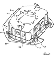
- Each of the side arms 27,28 of the wire 25 extends around the side walls 19 of the cover 3 and the free ends of the side arms 27,28 are terminated by a generally U-shaped bend in the wire 25, as shown in Figure 2 .
- Each of the free ends of the side arms 27,28 is positioned beneath one of the contact members 16 of one of the supports 13.
- the ends of the side sections 27,28 are terminated in a short flattened portions 31 which are configured to be connected to an electrical cable forming part of a horn circuit in a motor vehicle.
- each of the coil springs 24 is fitted around a respective one of the guide rods 23 on the cover 2.
- the cover 3 is moveably mounted to the housing 2 by nesting together the side walls 11 of the housing 2 with the side walls 19 of the cover 3.
- each of the hook-shaped elements 12 extends through a respective one of the rectangular apertures 20 in the cover 3.
- each of the supports 13 compresses a respective one of the coil springs 24.
- the cover 3 and the housing 2 have been pushed together they are then released so that the coil springs 24 bias the cover 3 away from the housing 2.
- the side walls 11 of the cover 3 move relative to the hook-shaped elements 12 of the housing 2 until the blocking edges 21 of the apertures 20 engage the hook-shaped elements 12 to prevent further movement of the cover 3 relative to the housing 2.
- the cover 3 is thus effectively hooked onto the housing 2 and held in an initial position by the hook-shaped elements 12 under bias by the coil springs 24.
- the cover 3 may be released subsequently from the housing 2 by pressing the cover 3 against the housing 2 so that the cover 3 moves by a distance of approximately 8 mm, which is the distance required to move the cover 3 so that the hooked part of the hook-shaped elements 12 is free to pass through the apertures 20.
- the wire 25 is clipped around the cover 3 to complete the assembly of the air-bag module 1.
- the wire 25 forms a barrier which prevents the cover 3 from being pressed towards the housing 2 by more than a distance of about 2 mm.
- the wire 25 blocks further movement of the cover 3 by engaging one or more of the supports 13 which each form part of the housing 2.
- the parts of the wire 25 which engage the supports 13 to block further movement of the cover 3 relative to the housing 2 are the parts of the wire 25 which extend between the indentations 22.
- the wire 25 blocks further movement of the wire 25 beyond about 2 mm from the initial position of the cover 3.
- the wire 25 can be unclipped from the cover 3 to allow the cover 3 to be moved towards the housing 2 over the distance of about 8 mm required to be able to unhook the cover 3 from the housing 2.
- the process of attachment of the wire 25 to the cover 3 is quick because of the simple nature of the clipping attachment.
- the wire 25 is cheap to produce because the wire 25 is a simple component, and since the wire 25 is a single integral component the wire 25 is less likely to break than a more complex horn circuit component which is constructed from more than one part.
- the air-bag module 1 can be mounted via the mounting tabs 7,8 to the steering wheel of a motor vehicle.
- the housing 2 is of metal and hence the housing 2 has been mounted to the steering wheel the metal housing 2 engages and is connected electrically to part of the steering wheel which is grounded to the chassis of the vehicle. The housing 2 is thus connected electrically to the ground of the vehicle's electrical system.
- One end of a cable can be connected to one of the flattened portions 31 of the wire 25 to connect the wire 25 to a horn circuit in the vehicle.
- the cover 3 When the cover 3 is in the initial position relative to the housing 2, that is to say when the cover 3 is held against the bias of the coil springs 24 by the hook shaped elements 12, the wire 25 is spaced apart from the contact members 16 on the housing 2. However, if the cover 3 is pressed towards the housing 2, for instance by a driver wishing to actuate the horn of the vehicle, the cover 3 moves against the bias of the coil springs 24 towards the housing 2 and the wire 25 is moved towards the contact members 16. If the cover 3 is depressed sufficiently (about 2 mm), the cover 3 moves to an actuating position in which the wire 25 contacts one or more of the contact members 16 to form an electrical connection between the wire 25 and one or more of the contact members 16, as shown in Figure 3 .
- the cable attached to the wire 25 effectively becomes connected to the ground, which completes the horn circuit to sound the horn of the vehicle. It will be appreciated that, whilst the wire 25 only needs to engage one of the contact members 16 to complete the electrical circuit, the wire 25 is engageable with all of the contact members 16 simultaneously if the cover 3 is depressed sufficiently.
- the driver can release the cover 3 and the cover 3 will be moved away from the housing 2 under the bias provided by the coil springs 24.
- the cover 3 returns to its initial position in which the wire 25 does not engage the contact members 16, and the horn circuit is thus not complete.
- the wire 25 and the contact members 16 can thus act as a switch in the electrical circuit in the vehicle which controls the vehicle's horn.
- the housing 2 is of metal
- the housing 2 may be of a plastics material.
- a metal member such as a metal plate can be mounted to each of the supports 13, with each of the metal plates being connected by a cable to part of the horn circuit. Consequently, the wire 25 is moved against one of the plates when the cover 3 is pressed to complete the horn circuit.
- the housing 2 is provided with the hook-shaped elements 12 and the cover 3 is provided with the apertures 20, in further embodiments this arrangement can be interchanged so that hook-shaped elements are provided on the walls 19 of the cover 3 and apertures are provided in the walls 11 of the housing 2.
- the direction in which the hook-shaped elements 12 face must be reversed so that the hook-shaped elements which are provided on the cover 3 can hold the cover 3 against the bias of the coil springs 24.
- the cover 3 will still be hooked to the housing 2 but able to move relative to the housing 2 when the cover 3 is pressed.
- the attachment formations are in the form of generally U-shaped indentations 22, in other embodiments the attachment formations may be a different shape. In such embodiments the attachment formations may be any shape, just as long as there are a plurality of spaced apart attachment formations provided on the cover which each retain part of a connection element to attach the connection element to the cover 3.
Landscapes
- Engineering & Computer Science (AREA)
- Mechanical Engineering (AREA)
- Physics & Mathematics (AREA)
- Acoustics & Sound (AREA)
- Chemical & Material Sciences (AREA)
- Combustion & Propulsion (AREA)
- Transportation (AREA)
- Air Bags (AREA)
- Steering Controls (AREA)
- Medicines Containing Plant Substances (AREA)
Applications Claiming Priority (1)
| Application Number | Priority Date | Filing Date | Title |
|---|---|---|---|
| PCT/SE2006/001493 WO2008079057A1 (en) | 2006-12-27 | 2006-12-27 | A safety arrangement |
Publications (3)
| Publication Number | Publication Date |
|---|---|
| EP2094538A1 EP2094538A1 (en) | 2009-09-02 |
| EP2094538A4 EP2094538A4 (en) | 2010-03-24 |
| EP2094538B1 true EP2094538B1 (en) | 2011-09-14 |
Family
ID=39562744
Family Applications (1)
| Application Number | Title | Priority Date | Filing Date |
|---|---|---|---|
| EP06835901A Not-in-force EP2094538B1 (en) | 2006-12-27 | 2006-12-27 | A safety arrangement |
Country Status (7)
| Country | Link |
|---|---|
| US (1) | US7946612B2 (ko) |
| EP (1) | EP2094538B1 (ko) |
| JP (1) | JP4967029B2 (ko) |
| KR (1) | KR101355446B1 (ko) |
| CN (1) | CN101583522B (ko) |
| AT (1) | ATE524353T1 (ko) |
| WO (1) | WO2008079057A1 (ko) |
Families Citing this family (11)
| Publication number | Priority date | Publication date | Assignee | Title |
|---|---|---|---|---|
| US8256797B2 (en) * | 2008-09-16 | 2012-09-04 | Toyoda Gosei Co., Ltd. | Steering wheel with airbag device and method for assembling the same |
| DE102010007569B4 (de) | 2010-02-10 | 2014-04-30 | Autoliv Development Ab | Sicherheitsanordnung |
| DE102011008158A1 (de) | 2011-01-10 | 2012-07-12 | Autoliv Development Ab | Hupenaktivierungseinrichtung |
| CN202077285U (zh) * | 2011-04-29 | 2011-12-14 | 博世汽车部件(苏州)有限公司 | 安全气囊控制器外壳 |
| JP5790311B2 (ja) * | 2011-08-24 | 2015-10-07 | タカタ株式会社 | 運転席用エアバッグ装置の取付構造及びステアリングホイール |
| KR101350521B1 (ko) * | 2011-12-06 | 2014-01-13 | 현대자동차주식회사 | 래틀방지용 에어백 스냅 피트 구조 |
| DE102016108516B4 (de) | 2016-05-09 | 2018-02-08 | Autoliv Development Ab | Airbaggehäuse für ein Airbagmodul |
| WO2017214214A2 (en) * | 2016-06-10 | 2017-12-14 | Key Safety Systems, Inc. | Air bag module |
| WO2018044254A1 (en) * | 2016-08-29 | 2018-03-08 | Trw Vehicle Safety Systems Inc. | Driver airbag mounting verification system |
| CN108216105B (zh) * | 2016-12-14 | 2021-08-31 | 奥托立夫开发公司 | 车辆的安全气囊模块 |
| CN110182158B (zh) * | 2019-05-17 | 2024-04-26 | 延锋汽车智能安全系统有限责任公司 | 一种安全气囊装置及其制造方法 |
Family Cites Families (30)
| Publication number | Priority date | Publication date | Assignee | Title |
|---|---|---|---|---|
| US6079737A (en) * | 1997-01-16 | 2000-06-27 | Toyoda Gosei Co., Ltd. | Steering wheel and horn switch assembly for the steering wheel |
| DE19927032A1 (de) * | 1999-06-04 | 2000-12-14 | Petri Ag | Anordnung zur Verrastung eines Airbagmoduls mit einem Lenkrad |
| JP3455499B2 (ja) | 1999-08-06 | 2003-10-14 | 本田技研工業株式会社 | エアバッグ装置及びステアリングホイール |
| US6719323B2 (en) * | 1999-08-06 | 2004-04-13 | Honda Giken Kogyo Kabushiki Kaisha | Air bag apparatus and steering wheel |
| JP3351404B2 (ja) * | 1999-10-14 | 2002-11-25 | 豊田合成株式会社 | エアバッグ装置のエアバッグ |
| JP4581244B2 (ja) | 2000-01-14 | 2010-11-17 | タカタ株式会社 | エアバッグ装置及びステアリングホイール |
| JP2001341605A (ja) * | 2000-05-31 | 2001-12-11 | Takata Corp | エアバッグ装置 |
| JP3481198B2 (ja) * | 2000-10-10 | 2003-12-22 | 本田技研工業株式会社 | エアバッグ装置 |
| DE20017527U1 (de) * | 2000-10-12 | 2001-02-22 | Trw Automotive Safety Sys Gmbh | Fahrzeuglenkrad |
| JP2002166808A (ja) * | 2000-11-30 | 2002-06-11 | Nippon Plast Co Ltd | エアバッグ装置 |
| GB2385834A (en) * | 2002-03-01 | 2003-09-03 | Autoliv Dev | Air bag mounting arrangement on vehicle steering wheel |
| US6719324B2 (en) * | 2002-03-29 | 2004-04-13 | Delphi Technologies, Inc. | Horn contact apparatus and method |
| DE20213908U1 (de) * | 2002-09-09 | 2003-01-30 | Trw Automotive Safety Sys Gmbh | Airbagmodul sowie Baugruppe aus einem Lenkrad und einem Airbagmodul |
| JP2004168284A (ja) * | 2002-11-01 | 2004-06-17 | Takata Corp | エアバッグ装置 |
| GB2398277A (en) * | 2003-02-13 | 2004-08-18 | Autoliv Dev | Spring mounted air bag cover with electrical switch |
| US7185915B2 (en) * | 2003-02-27 | 2007-03-06 | Toyoda Gosei Co., Ltd. | Steering wheel incorporating air bag device |
| JP2005038811A (ja) * | 2003-06-30 | 2005-02-10 | Takata Corp | ホーンスイッチ装置及びエアバッグ装置 |
| US7159897B2 (en) * | 2003-07-21 | 2007-01-09 | Delphi Technologies, Inc. | Isolated ground for horn mechanism |
| JP4322080B2 (ja) * | 2003-09-22 | 2009-08-26 | タカタ株式会社 | エアバッグ装置 |
| DE202004000953U1 (de) * | 2004-01-22 | 2004-05-27 | Trw Automotive Safety Systems Gmbh | Fahrzeuglenkrad |
| JP4301981B2 (ja) * | 2004-03-17 | 2009-07-22 | ナイルス株式会社 | 車両用コンビネーションスイッチ、その組立方法 |
| JP2006228700A (ja) | 2004-12-17 | 2006-08-31 | Tkj Kk | ホーンスイッチ装置、エアバッグ装置及びステアリングホイール |
| DE102005002945A1 (de) * | 2005-01-18 | 2006-07-27 | Takata-Petri Ag | Generatorträger für ein Fahrerairbagmodul zum Einbauen in ein Lenkrad eines Kraftfahrzeuges |
| US7621560B2 (en) * | 2005-02-07 | 2009-11-24 | Key Safety Systems, Inc | Horn switch |
| JP4797584B2 (ja) * | 2005-03-16 | 2011-10-19 | タカタ株式会社 | エアバッグ装置付きステアリングホイール |
| US7490852B2 (en) * | 2005-03-21 | 2009-02-17 | Delphi Technologies, Inc. | Apparatus and method for providing a horn contact mechanism |
| US7422236B2 (en) | 2005-03-21 | 2008-09-09 | Delphi Technologies, Inc. | Apparatus and method for providing a horn contact mechanism |
| WO2007013632A1 (ja) | 2005-07-28 | 2007-02-01 | Autoliv Development Ab | エアバッグ装置 |
| US7556282B2 (en) * | 2006-03-09 | 2009-07-07 | Toyoda Gosei Co. Ltd. | Steering wheel assembly |
| US7348508B2 (en) * | 2006-05-05 | 2008-03-25 | Delphi Technologies, Inc. | Horn switch apparatus for a vehicle steering wheel |
-
2006
- 2006-12-27 EP EP06835901A patent/EP2094538B1/en not_active Not-in-force
- 2006-12-27 JP JP2009543981A patent/JP4967029B2/ja not_active Expired - Fee Related
- 2006-12-27 CN CN2006800567858A patent/CN101583522B/zh not_active Expired - Fee Related
- 2006-12-27 KR KR1020097013248A patent/KR101355446B1/ko active IP Right Grant
- 2006-12-27 US US12/521,025 patent/US7946612B2/en not_active Expired - Fee Related
- 2006-12-27 WO PCT/SE2006/001493 patent/WO2008079057A1/en active Application Filing
- 2006-12-27 AT AT06835901T patent/ATE524353T1/de not_active IP Right Cessation
Also Published As
| Publication number | Publication date |
|---|---|
| KR101355446B1 (ko) | 2014-01-27 |
| US7946612B2 (en) | 2011-05-24 |
| US20100059974A1 (en) | 2010-03-11 |
| KR20090092821A (ko) | 2009-09-01 |
| JP4967029B2 (ja) | 2012-07-04 |
| EP2094538A4 (en) | 2010-03-24 |
| WO2008079057A1 (en) | 2008-07-03 |
| ATE524353T1 (de) | 2011-09-15 |
| CN101583522A (zh) | 2009-11-18 |
| JP2010514623A (ja) | 2010-05-06 |
| CN101583522B (zh) | 2012-08-29 |
| EP2094538A1 (en) | 2009-09-02 |
Similar Documents
| Publication | Publication Date | Title |
|---|---|---|
| EP2094538B1 (en) | A safety arrangement | |
| US7708309B2 (en) | Driver's airbag module assembly structure | |
| US6840537B2 (en) | Airbag module attachment arrangement | |
| JP3566693B2 (ja) | ステアリングホイール | |
| JP5033186B2 (ja) | エアバッグ・ユニットを自動車車両内のサブアセンブリ、特にステアリング・ホイールにスナップ固定するための装置 | |
| US7621560B2 (en) | Horn switch | |
| KR100539331B1 (ko) | 에어백 모듈과 주변 구조 사이에 일정한 갭을 유지하는장치 및 방법 | |
| US6951348B2 (en) | Rigid airbag plate attachment system | |
| EP2089253B1 (en) | An air-bag cover arrangement | |
| JP4870214B2 (ja) | ホーンアクチュエータ及びホーンアクチュエータを備える自動車用安全装置 | |
| JP2010501408A5 (ko) | ||
| JPH0818560B2 (ja) | ステアリングホイールのホーンスイッチ装置 | |
| KR20060130701A (ko) | 차량의 스티어링 휘일을 위한 스냅인 캐스터네츠 에어백모듈 | |
| US6250666B1 (en) | Airbag housing with horn mechanism | |
| US7690678B2 (en) | Air bag device | |
| JP3895896B2 (ja) | エアバッグモジュール | |
| JPH10129385A (ja) | エアバッグ装置 | |
| JP3865914B2 (ja) | エアバッグドアの構造 | |
| JPH08188109A (ja) | エアバッグ装置 | |
| JPH08192708A (ja) | エアバッグ装置 | |
| JPH10194070A (ja) | 運転席用エアバッグ装置 |
Legal Events
| Date | Code | Title | Description |
|---|---|---|---|
| PUAI | Public reference made under article 153(3) epc to a published international application that has entered the european phase |
Free format text: ORIGINAL CODE: 0009012 |
|
| 17P | Request for examination filed |
Effective date: 20090608 |
|
| AK | Designated contracting states |
Kind code of ref document: A1 Designated state(s): AT BE BG CH CY CZ DE DK EE ES FI FR GB GR HU IE IS IT LI LT LU LV MC NL PL PT RO SE SI SK TR |
|
| A4 | Supplementary search report drawn up and despatched |
Effective date: 20100223 |
|
| DAX | Request for extension of the european patent (deleted) | ||
| 17Q | First examination report despatched |
Effective date: 20100611 |
|
| GRAP | Despatch of communication of intention to grant a patent |
Free format text: ORIGINAL CODE: EPIDOSNIGR1 |
|
| GRAS | Grant fee paid |
Free format text: ORIGINAL CODE: EPIDOSNIGR3 |
|
| GRAA | (expected) grant |
Free format text: ORIGINAL CODE: 0009210 |
|
| AK | Designated contracting states |
Kind code of ref document: B1 Designated state(s): AT BE BG CH CY CZ DE DK EE ES FI FR GB GR HU IE IS IT LI LT LU LV MC NL PL PT RO SE SI SK TR |
|
| REG | Reference to a national code |
Ref country code: GB Ref legal event code: FG4D |
|
| REG | Reference to a national code |
Ref country code: CH Ref legal event code: EP |
|
| REG | Reference to a national code |
Ref country code: IE Ref legal event code: FG4D |
|
| REG | Reference to a national code |
Ref country code: DE Ref legal event code: R096 Ref document number: 602006024467 Country of ref document: DE Effective date: 20111208 |
|
| REG | Reference to a national code |
Ref country code: NL Ref legal event code: VDEP Effective date: 20110914 |
|
| PG25 | Lapsed in a contracting state [announced via postgrant information from national office to epo] |
Ref country code: FI Free format text: LAPSE BECAUSE OF FAILURE TO SUBMIT A TRANSLATION OF THE DESCRIPTION OR TO PAY THE FEE WITHIN THE PRESCRIBED TIME-LIMIT Effective date: 20110914 Ref country code: LT Free format text: LAPSE BECAUSE OF FAILURE TO SUBMIT A TRANSLATION OF THE DESCRIPTION OR TO PAY THE FEE WITHIN THE PRESCRIBED TIME-LIMIT Effective date: 20110914 Ref country code: SE Free format text: LAPSE BECAUSE OF FAILURE TO SUBMIT A TRANSLATION OF THE DESCRIPTION OR TO PAY THE FEE WITHIN THE PRESCRIBED TIME-LIMIT Effective date: 20110914 |
|
| LTIE | Lt: invalidation of european patent or patent extension |
Effective date: 20110914 |
|
| PG25 | Lapsed in a contracting state [announced via postgrant information from national office to epo] |
Ref country code: AT Free format text: LAPSE BECAUSE OF FAILURE TO SUBMIT A TRANSLATION OF THE DESCRIPTION OR TO PAY THE FEE WITHIN THE PRESCRIBED TIME-LIMIT Effective date: 20110914 Ref country code: LV Free format text: LAPSE BECAUSE OF FAILURE TO SUBMIT A TRANSLATION OF THE DESCRIPTION OR TO PAY THE FEE WITHIN THE PRESCRIBED TIME-LIMIT Effective date: 20110914 Ref country code: CY Free format text: LAPSE BECAUSE OF FAILURE TO SUBMIT A TRANSLATION OF THE DESCRIPTION OR TO PAY THE FEE WITHIN THE PRESCRIBED TIME-LIMIT Effective date: 20110914 Ref country code: SI Free format text: LAPSE BECAUSE OF FAILURE TO SUBMIT A TRANSLATION OF THE DESCRIPTION OR TO PAY THE FEE WITHIN THE PRESCRIBED TIME-LIMIT Effective date: 20110914 Ref country code: GR Free format text: LAPSE BECAUSE OF FAILURE TO SUBMIT A TRANSLATION OF THE DESCRIPTION OR TO PAY THE FEE WITHIN THE PRESCRIBED TIME-LIMIT Effective date: 20111215 |
|
| REG | Reference to a national code |
Ref country code: AT Ref legal event code: MK05 Ref document number: 524353 Country of ref document: AT Kind code of ref document: T Effective date: 20110914 |
|
| PG25 | Lapsed in a contracting state [announced via postgrant information from national office to epo] |
Ref country code: BE Free format text: LAPSE BECAUSE OF FAILURE TO SUBMIT A TRANSLATION OF THE DESCRIPTION OR TO PAY THE FEE WITHIN THE PRESCRIBED TIME-LIMIT Effective date: 20110914 |
|
| PG25 | Lapsed in a contracting state [announced via postgrant information from national office to epo] |
Ref country code: CZ Free format text: LAPSE BECAUSE OF FAILURE TO SUBMIT A TRANSLATION OF THE DESCRIPTION OR TO PAY THE FEE WITHIN THE PRESCRIBED TIME-LIMIT Effective date: 20110914 Ref country code: SK Free format text: LAPSE BECAUSE OF FAILURE TO SUBMIT A TRANSLATION OF THE DESCRIPTION OR TO PAY THE FEE WITHIN THE PRESCRIBED TIME-LIMIT Effective date: 20110914 Ref country code: IS Free format text: LAPSE BECAUSE OF FAILURE TO SUBMIT A TRANSLATION OF THE DESCRIPTION OR TO PAY THE FEE WITHIN THE PRESCRIBED TIME-LIMIT Effective date: 20120114 |
|
| PG25 | Lapsed in a contracting state [announced via postgrant information from national office to epo] |
Ref country code: IT Free format text: LAPSE BECAUSE OF FAILURE TO SUBMIT A TRANSLATION OF THE DESCRIPTION OR TO PAY THE FEE WITHIN THE PRESCRIBED TIME-LIMIT Effective date: 20110914 Ref country code: EE Free format text: LAPSE BECAUSE OF FAILURE TO SUBMIT A TRANSLATION OF THE DESCRIPTION OR TO PAY THE FEE WITHIN THE PRESCRIBED TIME-LIMIT Effective date: 20110914 Ref country code: RO Free format text: LAPSE BECAUSE OF FAILURE TO SUBMIT A TRANSLATION OF THE DESCRIPTION OR TO PAY THE FEE WITHIN THE PRESCRIBED TIME-LIMIT Effective date: 20110914 Ref country code: NL Free format text: LAPSE BECAUSE OF FAILURE TO SUBMIT A TRANSLATION OF THE DESCRIPTION OR TO PAY THE FEE WITHIN THE PRESCRIBED TIME-LIMIT Effective date: 20110914 Ref country code: PL Free format text: LAPSE BECAUSE OF FAILURE TO SUBMIT A TRANSLATION OF THE DESCRIPTION OR TO PAY THE FEE WITHIN THE PRESCRIBED TIME-LIMIT Effective date: 20110914 Ref country code: PT Free format text: LAPSE BECAUSE OF FAILURE TO SUBMIT A TRANSLATION OF THE DESCRIPTION OR TO PAY THE FEE WITHIN THE PRESCRIBED TIME-LIMIT Effective date: 20120116 |
|
| PLBE | No opposition filed within time limit |
Free format text: ORIGINAL CODE: 0009261 |
|
| STAA | Information on the status of an ep patent application or granted ep patent |
Free format text: STATUS: NO OPPOSITION FILED WITHIN TIME LIMIT |
|
| PG25 | Lapsed in a contracting state [announced via postgrant information from national office to epo] |
Ref country code: MC Free format text: LAPSE BECAUSE OF NON-PAYMENT OF DUE FEES Effective date: 20111231 Ref country code: DK Free format text: LAPSE BECAUSE OF FAILURE TO SUBMIT A TRANSLATION OF THE DESCRIPTION OR TO PAY THE FEE WITHIN THE PRESCRIBED TIME-LIMIT Effective date: 20110914 |
|
| REG | Reference to a national code |
Ref country code: CH Ref legal event code: PL |
|
| 26N | No opposition filed |
Effective date: 20120615 |
|
| GBPC | Gb: european patent ceased through non-payment of renewal fee |
Effective date: 20111227 |
|
| REG | Reference to a national code |
Ref country code: IE Ref legal event code: MM4A |
|
| REG | Reference to a national code |
Ref country code: DE Ref legal event code: R097 Ref document number: 602006024467 Country of ref document: DE Effective date: 20120615 |
|
| PG25 | Lapsed in a contracting state [announced via postgrant information from national office to epo] |
Ref country code: CH Free format text: LAPSE BECAUSE OF NON-PAYMENT OF DUE FEES Effective date: 20111231 Ref country code: GB Free format text: LAPSE BECAUSE OF NON-PAYMENT OF DUE FEES Effective date: 20111227 Ref country code: IE Free format text: LAPSE BECAUSE OF NON-PAYMENT OF DUE FEES Effective date: 20111227 Ref country code: LI Free format text: LAPSE BECAUSE OF NON-PAYMENT OF DUE FEES Effective date: 20111231 |
|
| PG25 | Lapsed in a contracting state [announced via postgrant information from national office to epo] |
Ref country code: ES Free format text: LAPSE BECAUSE OF FAILURE TO SUBMIT A TRANSLATION OF THE DESCRIPTION OR TO PAY THE FEE WITHIN THE PRESCRIBED TIME-LIMIT Effective date: 20111225 |
|
| PG25 | Lapsed in a contracting state [announced via postgrant information from national office to epo] |
Ref country code: LU Free format text: LAPSE BECAUSE OF NON-PAYMENT OF DUE FEES Effective date: 20111227 |
|
| PG25 | Lapsed in a contracting state [announced via postgrant information from national office to epo] |
Ref country code: BG Free format text: LAPSE BECAUSE OF FAILURE TO SUBMIT A TRANSLATION OF THE DESCRIPTION OR TO PAY THE FEE WITHIN THE PRESCRIBED TIME-LIMIT Effective date: 20111214 |
|
| PG25 | Lapsed in a contracting state [announced via postgrant information from national office to epo] |
Ref country code: TR Free format text: LAPSE BECAUSE OF FAILURE TO SUBMIT A TRANSLATION OF THE DESCRIPTION OR TO PAY THE FEE WITHIN THE PRESCRIBED TIME-LIMIT Effective date: 20110914 |
|
| PG25 | Lapsed in a contracting state [announced via postgrant information from national office to epo] |
Ref country code: HU Free format text: LAPSE BECAUSE OF FAILURE TO SUBMIT A TRANSLATION OF THE DESCRIPTION OR TO PAY THE FEE WITHIN THE PRESCRIBED TIME-LIMIT Effective date: 20110914 |
|
| REG | Reference to a national code |
Ref country code: FR Ref legal event code: PLFP Year of fee payment: 10 |
|
| REG | Reference to a national code |
Ref country code: FR Ref legal event code: PLFP Year of fee payment: 11 |
|
| REG | Reference to a national code |
Ref country code: FR Ref legal event code: PLFP Year of fee payment: 12 |
|
| PGFP | Annual fee paid to national office [announced via postgrant information from national office to epo] |
Ref country code: FR Payment date: 20171220 Year of fee payment: 12 |
|
| PGFP | Annual fee paid to national office [announced via postgrant information from national office to epo] |
Ref country code: DE Payment date: 20171221 Year of fee payment: 12 |
|
| REG | Reference to a national code |
Ref country code: DE Ref legal event code: R082 Ref document number: 602006024467 Country of ref document: DE Representative=s name: SCHOEN, THILO, DIPL.-PHYS., DE |
|
| REG | Reference to a national code |
Ref country code: DE Ref legal event code: R119 Ref document number: 602006024467 Country of ref document: DE |
|
| PG25 | Lapsed in a contracting state [announced via postgrant information from national office to epo] |
Ref country code: DE Free format text: LAPSE BECAUSE OF NON-PAYMENT OF DUE FEES Effective date: 20190702 Ref country code: FR Free format text: LAPSE BECAUSE OF NON-PAYMENT OF DUE FEES Effective date: 20181231 |