EP2070608A1 - Procédé de commande de refroidissement, unité de commande de refroidissement et unité de calcul de quantité d'eau de refroidissement - Google Patents
Procédé de commande de refroidissement, unité de commande de refroidissement et unité de calcul de quantité d'eau de refroidissement Download PDFInfo
- Publication number
- EP2070608A1 EP2070608A1 EP07768472A EP07768472A EP2070608A1 EP 2070608 A1 EP2070608 A1 EP 2070608A1 EP 07768472 A EP07768472 A EP 07768472A EP 07768472 A EP07768472 A EP 07768472A EP 2070608 A1 EP2070608 A1 EP 2070608A1
- Authority
- EP
- European Patent Office
- Prior art keywords
- cooling
- steel plate
- cooling water
- calculating
- heat transfer
- Prior art date
- Legal status (The legal status is an assumption and is not a legal conclusion. Google has not performed a legal analysis and makes no representation as to the accuracy of the status listed.)
- Granted
Links
- 238000001816 cooling Methods 0.000 title claims abstract description 333
- 239000000498 cooling water Substances 0.000 title claims abstract description 156
- 238000000034 method Methods 0.000 title claims abstract description 30
- 229910000831 Steel Inorganic materials 0.000 claims abstract description 143
- 239000010959 steel Substances 0.000 claims abstract description 143
- 238000004364 calculation method Methods 0.000 claims abstract description 71
- 238000005096 rolling process Methods 0.000 claims description 23
- 238000004590 computer program Methods 0.000 claims description 8
- 238000003860 storage Methods 0.000 claims description 4
- XLYOFNOQVPJJNP-UHFFFAOYSA-N water Substances O XLYOFNOQVPJJNP-UHFFFAOYSA-N 0.000 abstract description 44
- 230000006866 deterioration Effects 0.000 abstract description 8
- 238000009826 distribution Methods 0.000 description 10
- 238000004519 manufacturing process Methods 0.000 description 6
- 230000001133 acceleration Effects 0.000 description 3
- 238000010586 diagram Methods 0.000 description 2
- 230000006870 function Effects 0.000 description 2
- 239000007921 spray Substances 0.000 description 2
- 238000005507 spraying Methods 0.000 description 2
- 241000157049 Microtus richardsoni Species 0.000 description 1
- 238000009835 boiling Methods 0.000 description 1
- 230000003111 delayed effect Effects 0.000 description 1
- 238000005516 engineering process Methods 0.000 description 1
- 238000010438 heat treatment Methods 0.000 description 1
- 239000000463 material Substances 0.000 description 1
- 238000005259 measurement Methods 0.000 description 1
- 230000001629 suppression Effects 0.000 description 1
Images


Classifications
-
- B—PERFORMING OPERATIONS; TRANSPORTING
- B21—MECHANICAL METAL-WORKING WITHOUT ESSENTIALLY REMOVING MATERIAL; PUNCHING METAL
- B21B—ROLLING OF METAL
- B21B45/00—Devices for surface or other treatment of work, specially combined with or arranged in, or specially adapted for use in connection with, metal-rolling mills
- B21B45/02—Devices for surface or other treatment of work, specially combined with or arranged in, or specially adapted for use in connection with, metal-rolling mills for lubricating, cooling, or cleaning
-
- B—PERFORMING OPERATIONS; TRANSPORTING
- B21—MECHANICAL METAL-WORKING WITHOUT ESSENTIALLY REMOVING MATERIAL; PUNCHING METAL
- B21B—ROLLING OF METAL
- B21B37/00—Control devices or methods specially adapted for metal-rolling mills or the work produced thereby
- B21B37/74—Temperature control, e.g. by cooling or heating the rolls or the product
- B21B37/76—Cooling control on the run-out table
-
- C—CHEMISTRY; METALLURGY
- C21—METALLURGY OF IRON
- C21D—MODIFYING THE PHYSICAL STRUCTURE OF FERROUS METALS; GENERAL DEVICES FOR HEAT TREATMENT OF FERROUS OR NON-FERROUS METALS OR ALLOYS; MAKING METAL MALLEABLE, e.g. BY DECARBURISATION OR TEMPERING
- C21D1/00—General methods or devices for heat treatment, e.g. annealing, hardening, quenching or tempering
- C21D1/62—Quenching devices
- C21D1/667—Quenching devices for spray quenching
-
- C—CHEMISTRY; METALLURGY
- C21—METALLURGY OF IRON
- C21D—MODIFYING THE PHYSICAL STRUCTURE OF FERROUS METALS; GENERAL DEVICES FOR HEAT TREATMENT OF FERROUS OR NON-FERROUS METALS OR ALLOYS; MAKING METAL MALLEABLE, e.g. BY DECARBURISATION OR TEMPERING
- C21D11/00—Process control or regulation for heat treatments
- C21D11/005—Process control or regulation for heat treatments for cooling
-
- G—PHYSICS
- G06—COMPUTING; CALCULATING OR COUNTING
- G06F—ELECTRIC DIGITAL DATA PROCESSING
- G06F9/00—Arrangements for program control, e.g. control units
-
- B—PERFORMING OPERATIONS; TRANSPORTING
- B21—MECHANICAL METAL-WORKING WITHOUT ESSENTIALLY REMOVING MATERIAL; PUNCHING METAL
- B21B—ROLLING OF METAL
- B21B45/00—Devices for surface or other treatment of work, specially combined with or arranged in, or specially adapted for use in connection with, metal-rolling mills
- B21B45/02—Devices for surface or other treatment of work, specially combined with or arranged in, or specially adapted for use in connection with, metal-rolling mills for lubricating, cooling, or cleaning
- B21B45/0203—Cooling
- B21B45/0209—Cooling devices, e.g. using gaseous coolants
- B21B45/0215—Cooling devices, e.g. using gaseous coolants using liquid coolants, e.g. for sections, for tubes
- B21B45/0218—Cooling devices, e.g. using gaseous coolants using liquid coolants, e.g. for sections, for tubes for strips, sheets, or plates
Definitions
- the present invention relates to a cooling control method, a cooling control apparatus, a cooling water amount calculation apparatus, a computer program, and a storage medium in a process of production of steel plate, more particularly relates to technology preferred for use for cooling steel plate immediately after rolling.
- cooling control designed to measure the temperature of the steel plate during cooled processing, change the amounts of cooling water sprayed on a top surface and a bottom surface of the steel plate so that a cooling end temperature becomes a desired temperature, and eliminating a difference between a top surface temperature and a bottom surface temperature of the steel plate so as to prevent shape deterioration of the steel plate occurring due to the difference between the top surface temperature and the bottom surface temperature of the steel plate has been proposed (see for example Japanese Patent Publication (B2) No. 7-41303 ).
- a top/bottom ratio of amounts of cooling water is determined by a coefficient determined from the size etc. of the cooled material.
- the steel plate temperature during cooling largely depends upon the amounts of cooling water and heat transfer coefficient. Namely, the heat transfer coefficient is a function of the surface temperature of the steel plate.
- the cooling method disclosed in Japanese Patent Publication (B2) No. 7-29139 predicts the temperature at the time of the cooling start based on the temperature at the time of the rolling end and calculates continuously changing surface temperature state and heat transfer coefficient by using a heat transfer formula using the predicted temperatures as the initial state so as to determine the water top/bottom ratio suppressing the deterioration of shape of the steel plate during cooling with a high precision.
- the cooling top/bottom water rate ratio is calculated according to the temperatures measured at the cooling start position and the water top/bottom ratio giving a constant top/bottom temperature distribution is searched for and calculated by using a heat transfer formula considering the continuously changing surface temperature state and heat transfer coefficient.
- an object of the present invention is to quickly control the amounts of cooling water sprayed from top and bottom surfaces of the cooling apparatus when cooling steel plate to a predetermined cooling end temperature so as to prevent shape deterioration of steel plate occurring due to the difference of cooling rates between the top surface and the bottom surface with a high precision.
- the present invention was made so as to solve the above problem and has as its gist the following:
- the cooling control method of the present invention is a cooling control method for cooling steel plate by a cooling apparatus immediately after rolling, comprising a cooling schedule setting step of calculating cooling conditions required for cooling the steel plate to a predetermined temperature for a plurality of positions inside the cooling apparatus based on measured temperatures at a time when the steel plate passes through the cooling apparatus by a thermometer disposed at the entry-side of the cooling apparatus and setting a cooling schedule; a heat transfer coefficient calculation step of calculating a heat transfer coefficient showing an ease of conduction of heat from the temperature in the cooling schedule set by the cooling schedule setting step and the first cooling water density in cooling water for cooling one surface of the steel plate; a top/bottom ratio calculation step of calculating the second cooling water density in the cooling water for cooling an opposite surface of the steel plate from the heat transfer coefficient calculated by the heat transfer coefficient calculation step and calculating the top/bottom ratio between the first cooling water density and the second cooling water density; and a cooling water amount controlling step of controlling the amounts of cooling water for cooling the steel plate passing through the cooling apparatus based on the top/bottom
- the cooling control apparatus of the present invention is a cooling control apparatus for cooling steel plate by a cooling apparatus immediately after rolling, comprising a cooling schedule setting means for calculating cooling conditions required for cooling the steel plate to a predetermined temperature for a plurality of positions inside the cooling apparatus based on measured temperatures at a time when the steel plate passes through the cooling apparatus by a thermometer disposed at the entry-side of the cooling apparatus and setting a cooling schedule; a heat transfer coefficient calculating means for calculating a heat transfer coefficient showing an ease of conduction of heat from the temperature in the cooling schedule set by the cooling schedule setting means and a first cooling water density in cooling water for cooling one surface of the steel plate; a top/bottom ratio calculating means for calculating a second cooling water density in the cooling water for cooling an opposite surface of the steel plate from the heat transfer coefficient calculated by the heat transfer coefficient calculating means and calculating the top/bottom ratio between the first cooling water density and the second cooling water density; and a cooling water amount controlling means for controlling the amounts of cooling water for cooling the steel plate passing through the cooling apparatus based
- the cooling water amount calculation apparatus of the present invention is a cooling water amount calculation apparatus for calculating amounts of cooling water required for cooling steel plate by a cooling apparatus immediately after rolling, comprising a cooling schedule setting means for calculating cooling conditions required for cooling the steel plate to a predetermined temperature for a plurality of positions inside the cooling apparatus based on measured temperatures at a time when the steel plate passes through the cooling apparatus by a thermometer disposed at the entry-side of the cooling apparatus and setting a cooling schedule; a heat transfer coefficient calculating means for calculating a heat transfer coefficient showing an ease of conduction of heat from the temperature in the cooling schedule set by the cooling schedule setting means and a first cooling water density in cooling water for cooling one surface of the steel plate; and a top/bottom ratio calculating means for calculating a second cooling water density in the cooling water for cooling an opposite surface of the steel plate from the heat transfer coefficient calculated by the heat transfer coefficient calculating means and calculating the top/bottom ratio between the first cooling water density and the second cooling water density.
- the computer program of the present invention is characterized in that the computer is made to execute the cooling control method disclosed before.
- the storage medium of the present invention is characterized in that the computer program disclosed above is stored.
- cooling conditions required until the steel plate is cooled to the predetermined temperature are calculated for a plurality of positions inside the cooling apparatus based on the measurement values of the temperatures when the steel plate passes through the inside of the cooling apparatus by a thermometer disposed at the entry-side of the cooling apparatus and the cooling schedule is set, a heat transfer coefficient showing the ease of the conduction of the heat is calculated from the temperature in the set scheduled cooling schedule and the first cooling water density in the cooling water for cooling one surface of the steel plate, the second cooling water density in the cooling water for cooling the opposite surface of the steel plate is calculated from the calculated heat transfer coefficient, and the amount of the cooling water for cooling the steel plate passing through the cooling apparatus is controlled based on the top/bottom ratio between the first cooling water density and the second cooling water density, therefore the calculation amount required for controlling the amounts of cooling water sprayed from the top and bottom surfaces of the cooling apparatus to cool the steel plate to the predetermined cooling end temperature can be simplified.
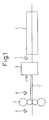
- FIG. 1 shows an example of a steel plate production line to which the present invention is applied.
- a finish rolling mill 2 for rolling steel plate 1 roughly formed by passing through a not shown heating furnace or rough rolling mill down to a target plate thickness, a straightener 3 for straightening the shape of the steel plate 1 after the finish rolling, and a cooling apparatus 4 for acceleratedly cooling the steel plate 1 are successively arranged.
- the accelerated cooled steel plate 1 becomes a product of the desired shape and quality.
- thermometer 5 is arranged at the entry-side of the finish rolling mill 2, while a final exit-side thermometer 6 is arranged at the exit side. Further, a cooling entry-side thermometer 7 is arranged at the entry-side of the cooling apparatus 4. In the present embodiment, the thermometers can measure the temperatures of the top surface and bottom surface of the steel plate 1.
- FIG. 2 is a view showing an example of the internal configuration of the cooling apparatus 4.
- a large number of groups of rollers 4 conveying the steel plate 1 are arranged and a large number of groups of nozzles (not shown) spraying cooling water to the top surface and bottom surface of the steel plate 1 are arranged in the cooling zones 1Z to 19Z.
- the sprays of the cooling water from these groups of nozzles are controlled by the flow rate control valves.
- the number of usage zones and the amounts of spray from the nozzles can be adjusted by the plate thickness or plate length of the steel plate and other conditions.
- the cooling entry-side thermometer 7 is arranged at the entry-side of the cooling apparatus 4.
- FIG. 3 is a block diagram showing the schematic configuration of a control system including a cooling water amount calculation apparatus 100 of the present embodiment.
- the cooling water amount calculation apparatus 100 has a rolling control apparatus 200 for overall control of the rolling mills including the finish rolling mill 2, a production control apparatus 300 mainly production control, a data input/output device 400 displaying various types of data output from the cooling water amount calculation apparatus 100 and outputting the input from the operator to the cooling water amount calculation apparatus 100, and a cooling inlet side thermometer 7 connected to it.
- the cooling water amount calculation apparatus 100 has a cooling water amount control apparatus 500 for controlling flow rate control valves 501 in cooling zones 1Z to 19Z of the cooling apparatus 4 to control the amounts of cooling water rates connected to it.
- the cooling water amount calculation apparatus 100 calculates the amounts of cooling water controlled by the cooling water control apparatus 500 based on the data input from the cooling entry-side thermometer 7, the rolling control apparatus 200, the production control apparatus 300, the data input/output device 400, etc.
- the cooling water amount calculation apparatus 100 of the present embodiment determines the amounts of the sprayed water of the cooling apparatus 4 by transmitting the data concerning the required amounts of cooling water to the cooling water amount control apparatus 500 while conveying the steel plate 1 after the finishing.
- the cooling water amount calculation apparatus 100 of the present embodiment is provided with a cooling schedule setting unit 101 for setting the cooling schedule of the steel plate 1 by the cooling apparatus 4 in accordance with target cooling end temperature information, a heat transfer coefficient calculation unit 102 for acquiring the heat transfer coefficient at a predetermined part of the steel plate 1 at the entry-side of the cooling apparatus 4, and a top/bottom ratio calculation unit 103 for calculating the water density ratio of the top surface and bottom surface reflected in the cooling water amount control apparatus 500 based on the cooling schedule set by the cooling schedule setting unit 101 and the heat transfer coefficient acquired by the heat transfer coefficient calculation unit 102.
- FIG. 4 is a flow chart showing an example of the routine for determining the amounts of cooling water by the cooling water amount calculation apparatus 100 in the present embodiment.
- the cooling schedule setting unit 101 sets the cooling schedule of the steel plate 1 by the cooling apparatus 4. Specifically, it performs processing for measuring the surface temperature of the steel plate 1 measured by the cooling entry-side thermometer 7 and finding the temperature distribution in the plate thickness direction at each segment at a point of time immediately before cooling.
- the temperature distribution in the plate thickness direction exhibits a parabolic shape where the temperature becomes the highest at a middle position in the plate thickness direction. Further, as the technique for finding the temperature distribution in the plate thickness direction from surface temperatures, for example, it is possible to determine the temperature distribution of 11 points in the plate thickness direction by using the technique disclosed in Japanese Patent Publication (B2) No. 7-41303 (see FIG. 7 ). Explaining this in brief, the top surface temperature T F is the measured temperature.
- ⁇ T 33.8 - 3.63 ⁇ h ⁇ - 0.0371 + 0.00528 ⁇ h ⁇ TF
- ⁇ T temperature difference between top surface and highest point of plate temperature
- h plate thickness
- T L T F + K 1 ⁇ ⁇ ⁇ ⁇ ⁇ T S ⁇ con + ⁇ ⁇ T S ⁇ class + K 2
- ⁇ temperature transform coefficient obtained by learning
- ⁇ T S entry-side temperature top/bottom surface temperature difference obtained by learning
- K 1 , K 2 adjustment elements.
- the parabolic temperature distribution satisfying the above conditions is determined, and the temperature distribution in the plate thickness direction is determined.
- the average temperature Tsk* in the plate thickness direction at the different segments at the cooling start position of the cooling apparatus 4 (hereinafter referred to as the "cooling start temperature Tsk*", k being a thickness direction index) is calculated as the cooling start temperature information.
- the technique for analyzing the trends in temperature by solving the difference equation of heat conduction as disclosed in for example Japanese Patent Publication (B2) No.
- the cooling schedule setting unit 101 calculates and sets the passage times (TMz) and cooling prediction temperatures (Tsk) in the zones based on the cooling plate threading speeds in the zones (1Z to 19Z).
- the cooling prediction temperature (Tsk) shows the entry-side temperature in one of the divided areas in each zone.
- the cooling plate threading speed is given by a set of the position of the front end of the plate and the data of the conveyance speed by the method disclosed in Japanese Patent Publication (B2) No. 7-41303 .
- the position of the front end of the plate is defined as x and the conveyance speed at this time is V(x)
- the water cooling time of the k point on the plate at the entry of the cooling apparatus at that point of time is given by: t x ⁇ ⁇ x x - Lzone ⁇ 1 V x ⁇ dx
- the acceleration range (definition area of x) is found as in the following equation: 0 ⁇ x ⁇ L + zone + ⁇ ⁇ c 2 , L: plate length,
- c 2 : excess margin ( const)
- x is suitably determined within a determined acceleration range and entered into the formula of V(x) to prepare a set of the position of the front end of the steel plate and the conveyance at that point of time (speed pattern). Then, the results of the calculation are output to the threading speed control apparatus (not shown).
- the acceleration ratio is found in this way because the steel plate 1 is cooled while being conveyed, so the timings of entering to the cooling apparatus 4 differ between the front end and tail end of the steel plate. Namely, the cooling start temperature differs along the longitudinal direction of the steel plate, therefore the temperature after cooling ends up becoming different between the front end and the tail end. To make the quality of the product uniform over the entire length, the threading speed is made faster the more toward the tail end so as to eliminate the difference.
- the cooling schedule up to the cooling end target temperature is acquired due to the above.
- the heat transfer coefficient calculation unit 102 selects a reference water density corresponding to the zone Z being calculated from the zone reference water densities and enters it into the cooling lower water density (WDLi).
- WDLi cooling lower water density
- the method of determining the reference water density of each zone as shown in for example Japanese Patent Publication (B2) No. 7-41303 , use can be made of for example the method of determining the reference water density according to the value transmitted from a business computer.
- the heat transfer coefficient calculation unit 102 calculates the difference of heat conduction using the cooling prediction temperature (Tsk) as the initial value and calculates the steel plate bottom surface temperature (TLi).
- Tsk cooling prediction temperature
- Tsk* the value of Tsk in a first iteration calculation in the zone 1Z. Otherwise, the results of iteration calculation become Tsk.
- the lower heat transfer coefficient (aLi) is found from the calculated cooling lower water density (WDLi) and the steel plate bottom surface temperature (TLi).
- FIG. 10 is a graph showing the trends in the cooling temperature in the present embodiment.
- the steel plate bottom surface temperature (TLi) indicates for example the entry-side bottom surface temperature in 1 iteration in the zone 1Z.
- the difference of heat conduction is calculated by using the cooling prediction temperature (Tsk) as the initial value.
- the steel plate bottom surface temperature (TLi) is calculated in each iteration.
- the heat transfer coefficient (a) is generally a nonlinear function determined by the water density WD (m 3 /(m 2 ⁇ min)) and the surface temperature Ts.
- the heat transfer coefficient (a) is generally a nonlinear function determined by the water density WD (m 3 /(m 2 ⁇ min)) and the surface temperature Ts.
- Equation (4) is generally subjected to coefficient division by surface temperature as follows for the coefficients A, B, C, and D in Equation (4): Ts ⁇ K ⁇ 1 ⁇ A ⁇ 1 , B ⁇ 1 , C ⁇ 1 , D ⁇ 1 , Ts ⁇ K ⁇ 1 ⁇ A ⁇ 2 , B ⁇ 2 , C ⁇ 2 , D ⁇ 2.
- the heat transfer coefficient is calculated by selective use of the following coefficient sets.
- the coefficients for calculation of the upper heat transfer coefficients the following are used: Ts U ⁇ K ⁇ 1 U ⁇ A ⁇ 1 U , B ⁇ 1 U , C ⁇ 1 U , D ⁇ 1 U and Ts U ⁇ K ⁇ 1 U ⁇ A ⁇ 2 U , B ⁇ 2 U , C ⁇ 2 U , D ⁇ 2 U
- FIG. 5 is a graph showing the relationship between the steel plate bottom surface temperature and the lower heat transfer coefficient in the present embodiment.
- the top/bottom ratio calculation unit 103 calculates the cooling upper water density (WDUi) by using the lower heat transfer coefficient (aLi) calculated at step S403 and calculates the suitable top/bottom ratio ( ⁇ i) in the iteration.
- FIG. 6 is a view showing the relationship between the steel plate top surface temperature (TUi) and the upper heat transfer coefficient (aUi) in the present embodiment.
- the curve pattern of the cooling lower water density (WDLi) a plurality of curve patterns of the cooling upper water density (WDUi) are stored as well, but when the corresponding curve pattern is not stored, the cooling upper water density (WDUi) is directly calculated.
- FIG. 9 is a view showing a method of searching for the cooling upper water density (WDUi) in the present embodiment.
- the cooling upper water density (WDUi) with which the upper heat transfer coefficient (aUi) becomes the same as the lower heat transfer coefficient (aLi) is searched for and calculated while changing the cooling water density WDU.
- FIG. 11 is a flow chart showing the routine for calculating the cooling upper water density (WDUi) by the top/bottom ratio calculation unit 103.
- the upper standard heat transfer coefficient (a 0 ) is a non-reference surface heat transfer coefficient corresponding to the standard water density (WDU*) and is calculated by Equation (4). Further, the standard water density (WDU*) is stored in advance as data.
- step S1102 it is judged whether or not the upper standard heat transfer coefficient (a 0 ) is larger than the lower heat transfer coefficient (aLi).
- the routine jumps to step S1106.
- the routine proceeds to step S1103.
- step S1104 it is judged whether or not the heat transfer coefficient (a k+1 ) corresponding to WDU k+1 calculated at step S1103 matches with the lower heat transfer coefficient (aLi).
- step S1105 it is judged at step S1105 whether or not the above calculated heat transfer coefficient (a k+1 ) is larger than the lower heat transfer coefficient (aLi).
- step S1106 When the result of this judgment is that the above calculated heat transfer coefficient (a k+1 ) is smaller than the lower heat transfer coefficient (aLi), the routine returns to step S1103, where 1 is added to k, then the calculation is carried out in the same way again. On the other hand, when the result of the judgment of step S1105 is that the above (a k+1 ) is larger than the above (aLi), the routine proceeds to step S1106.
- step S1106 When the result of this judgment is that the above calculated heat transfer coefficient (a k+1 ) is larger than the above lower heat transfer coefficient (aLi), the routine returns to step S1106, where 1 is added to the value k, and the calculation is carried out in the same way again.
- step S1103 when the result of the judgment of step S1108 is that the above (a k+1 ) is smaller than the above (aLi), the routine proceeds to step S1103, where 1 is added to the value k, and the calculation is carried out in the same way again. As described above, the calculation is repeatedly carried out until the above calculated heat transfer coefficient (a k+1 ) matches with the lower heat transfer coefficient (aLi).
- the suitable top/bottom ratio of the iteration is calculated.
- step S405 the top/bottom ratio calculation unit 103 judges whether or not all of iterations end for one zone. When the result of this judgment is that they have not ended, the routine returns to step S403, where the calculation is repeated again. On the other hand, when the result of the judgment of step S405 is that the iterations end, the routine proceeds to the next step S406.
- the number of iterations may be freely set, but the number of iterations is determined so that ETM ⁇ TMz always stands when multiplying the number of iterations (I) by 1 iteration time (TM*) to calculate the elapsed time (ETM).
- the top/bottom ratio calculation unit 103 calculates an average value (AVE( ⁇ i)) of the suitable top/bottom ratios ( ⁇ i) of the iterations and finally defines that average value as the suitable zone top/bottom ratio ( ⁇ z).
- step S407 the heat transfer coefficient calculation unit 102 judges whether or not there is a next zone not calculated.
- the routine returns to step S402, where the calculation is carried out again in order to calculate the suitable zone top/bottom ratio ( ⁇ i) for the next zone.
- the routine proceeds to the next step S408.
- the cooling water amount calculation apparatus 100 transmits the data of all suitable zone top/bottom ratios ( ⁇ z) to the cooling water amount control apparatus 500, and the cooling water amount control apparatus 500 adjusts the flow rate control valves 501 of the cooling apparatus 4 based on that data and runs cooling water to the nozzles. Due to this, in the present embodiment, cooling water in all zones can be made to flow before the front end of the steel plate 1 enters the cooling apparatus 4.
- step S408 the cooling schedule setting unit 101 judges whether or not the portion measured for temperature by the cooling entry-side thermometer 7 was the front end of the steel plate 1. When the result of this judgment is that the measured portion was the tail end of the steel plate, all processing is ended. On the other hand, when result of the judgment of step S408 is that the measured portion was not the tail end of the steel plate 1, the routine returns to step S401, where the cooling schedule is newly acquired for the next portion in the steel plate 1.
- the plate threading speed is made faster toward the tail end in order to make the product quality of the steel plate 1 uniform over the entire length.
- the cooling schedule of the steel plate 1 differs according to the position of the steel plate 1. Accordingly, in the present embodiment, the steel plate 1 is divided into a plurality of portions and the cooling schedule is acquired for each portion.
- the cooling upper water density (WDUi) and the cooling lower water density (WDLi) are determined as explained before, therefore, in order to cool the steel plate 1 to the previously determined cooling end temperature, the calculation amount required for controlling the amounts of cooling waters sprayed from the top and bottom surfaces of the cooling apparatus 4 can be simplified. Due to this, cooling water can be run in all zones 1Z to 19Z before the front end of the steel plate 1 enters to the cooling apparatus 4, and the deterioration of the steel plate shape can be suppressed to the smallest limit.
- the cooling water amount calculation apparatus 100 of the embodiment explained before is specifically configured by a computer apparatus or a computer system including a CPU, RAM, ROM, etc. Therefore, the computer program itself installed in a computer to realize the functional processing of the present invention is also included in the present invention.
Landscapes
- Engineering & Computer Science (AREA)
- Chemical & Material Sciences (AREA)
- Mechanical Engineering (AREA)
- Physics & Mathematics (AREA)
- Materials Engineering (AREA)
- Crystallography & Structural Chemistry (AREA)
- Thermal Sciences (AREA)
- Metallurgy (AREA)
- Organic Chemistry (AREA)
- Theoretical Computer Science (AREA)
- Software Systems (AREA)
- General Engineering & Computer Science (AREA)
- General Physics & Mathematics (AREA)
- Control Of Metal Rolling (AREA)
- Control Of Heat Treatment Processes (AREA)
Applications Claiming Priority (1)
| Application Number | Priority Date | Filing Date | Title |
|---|---|---|---|
| PCT/JP2007/064618 WO2009011070A1 (fr) | 2007-07-19 | 2007-07-19 | Procédé de commande de refroidissement, unité de commande de refroidissement et unité de calcul de quantité d'eau de refroidissement |
Publications (3)
| Publication Number | Publication Date |
|---|---|
| EP2070608A1 true EP2070608A1 (fr) | 2009-06-17 |
| EP2070608A4 EP2070608A4 (fr) | 2010-05-05 |
| EP2070608B1 EP2070608B1 (fr) | 2012-09-05 |
Family
ID=40259419
Family Applications (1)
| Application Number | Title | Priority Date | Filing Date |
|---|---|---|---|
| EP07768472A Active EP2070608B1 (fr) | 2007-07-19 | 2007-07-19 | Procédé de commande de refroidissement, unité de commande de refroidissement et unité de calcul de quantité d'eau de refroidissement |
Country Status (7)
| Country | Link |
|---|---|
| US (1) | US9364879B2 (fr) |
| EP (1) | EP2070608B1 (fr) |
| KR (1) | KR100977373B1 (fr) |
| CN (1) | CN101489696B (fr) |
| BR (1) | BRPI0702835B1 (fr) |
| RU (1) | RU2404000C2 (fr) |
| WO (1) | WO2009011070A1 (fr) |
Cited By (7)
| Publication number | Priority date | Publication date | Assignee | Title |
|---|---|---|---|---|
| EP2361699A1 (fr) | 2010-02-26 | 2011-08-31 | Siemens Aktiengesellschaft | Procédé de refroidissement d'une tôle à l'aide d'un tunnel de refroidissement, tunnel de refroidissement et dispositif de commande et/ou de réglage pour un tunnel de refroidissement |
| CN102399950A (zh) * | 2011-11-30 | 2012-04-04 | 东北大学 | 一种中厚板淬火工艺的控制方法 |
| CN102596440A (zh) * | 2009-11-24 | 2012-07-18 | 住友金属工业株式会社 | 热轧钢板的制造方法和热轧钢板的制造装置 |
| CN103447315A (zh) * | 2012-05-31 | 2013-12-18 | 宝山钢铁股份有限公司 | 一种基于板形的acc流量控制方法及装置 |
| EP2929949A4 (fr) * | 2012-12-06 | 2016-07-06 | Nippon Steel & Sumitomo Metal Corp | Dispositif permettant de refroidir une tôle d'acier laminée à chaud |
| US9566625B2 (en) | 2011-06-07 | 2017-02-14 | Nippon Steel & Sumitomo Metal Corporation | Apparatus for cooling hot-rolled steel sheet |
| EP3060358B1 (fr) | 2013-10-25 | 2017-11-15 | SMS group GmbH | Train de laminage à chaud de bandes d'aluminium et procédé de laminage à chaud d'une bande d'aluminium |
Families Citing this family (14)
| Publication number | Priority date | Publication date | Assignee | Title |
|---|---|---|---|---|
| CN101885004B (zh) * | 2010-06-13 | 2012-08-22 | 南京钢铁股份有限公司 | 低合金高强度钢板在控制冷却阶段的板型控制方法 |
| CN102759935A (zh) * | 2011-04-25 | 2012-10-31 | 蔺桃 | 一种新型冷却控制方法 |
| US9186710B2 (en) | 2011-06-07 | 2015-11-17 | Nippon Steel & Sumitomo Metal Corporation | Method for cooling hot-rolled steel sheet |
| US9211574B2 (en) | 2011-07-27 | 2015-12-15 | Nippon Steel & Sumitomo Metal Corporation | Method for manufacturing steel sheet |
| EP2764932B1 (fr) * | 2012-12-06 | 2018-02-07 | Nippon Steel & Sumitomo Metal Corporation | Procédé permettant de refroidir une tôle d'acier laminée à chaud |
| TWI476398B (zh) * | 2013-05-22 | 2015-03-11 | China Steel Corp | Correction Method of Water Heat and Heat Transfer Coefficient |
| CN103464474B (zh) * | 2013-08-12 | 2015-07-29 | 北京首钢自动化信息技术有限公司 | 棒材控冷系统的温度自动控制方法 |
| JP6275525B2 (ja) * | 2014-03-27 | 2018-02-07 | 株式会社神戸製鋼所 | 厚鋼板の冷却方法及び厚鋼板の製造方法並びに厚鋼板冷却装置 |
| US11891309B2 (en) | 2017-09-19 | 2024-02-06 | Ecolab Usa Inc. | Cooling water monitoring and control system |
| EP3707457B1 (fr) | 2017-11-10 | 2022-09-28 | Ecolab USA, Inc. | Procédé de surveillance et de commande d'eau de refroidissement |
| DE212019000307U1 (de) * | 2018-06-13 | 2021-02-02 | Novelis Inc. | Systeme zum Abschrecken eines Metallstreifens nach einem Walzen |
| BR112021015315A2 (pt) * | 2019-02-07 | 2021-10-05 | Jfe Steel Corporation | Método para realizar o controle de resfriamento, dispositivo de controle de resfriamento e método de fabricação de uma chapa de aço |
| DE102019216261A1 (de) * | 2019-07-02 | 2021-01-07 | Sms Group Gmbh | Verfahren zur Steuerung einer Kühleinrichtung in einer Walzstraße |
| CN110899339A (zh) * | 2019-12-04 | 2020-03-24 | 广西柳州银海铝业股份有限公司 | 轧机热成像板形控制方法 |
Citations (4)
| Publication number | Priority date | Publication date | Assignee | Title |
|---|---|---|---|---|
| JPS61219412A (ja) * | 1985-03-26 | 1986-09-29 | Kawasaki Steel Corp | 熱鋼板の均一冷却方法およびその装置 |
| JPH0270018A (ja) * | 1988-09-05 | 1990-03-08 | Nippon Steel Corp | 熱鋼板の冷却方法 |
| JPH02179825A (ja) * | 1988-12-28 | 1990-07-12 | Nippon Steel Corp | 熱間圧延鋼板の冷却制御装置 |
| JPH04232214A (ja) * | 1990-12-28 | 1992-08-20 | Nippon Steel Corp | 鋼板の冷却制御方法及びその装置 |
Family Cites Families (25)
| Publication number | Priority date | Publication date | Assignee | Title |
|---|---|---|---|---|
| US4047985A (en) * | 1976-02-09 | 1977-09-13 | Wean United, Inc. | Method and apparatus for symmetrically cooling heated workpieces |
| SU1030060A1 (ru) | 1981-05-18 | 1983-07-23 | Киевский институт автоматики им.ХХУ съезда КПСС | Способ автоматического управлени ускоренным охлаждением полосы на стане гор чей прокатки |
| JPS60174833A (ja) * | 1984-02-20 | 1985-09-09 | Nippon Steel Corp | 熱鋼板の冷却方法 |
| JPS60174834A (ja) | 1984-02-21 | 1985-09-09 | Kawasaki Steel Corp | 板の冷却制御方法 |
| JPS60210313A (ja) | 1984-04-04 | 1985-10-22 | Kobe Steel Ltd | 鋼板冷却方法 |
| CA1265421A (fr) * | 1985-10-31 | 1990-02-06 | Norio Anzawa | Methode et dispositif de refroidissement des aciers venant du laminage |
| SU1297960A1 (ru) | 1985-11-10 | 1987-03-23 | Киевский институт автоматики им.ХХУ съезда КПСС | Способ управлени ускоренным охлаждением проката и устройство дл его осуществлени |
| SU1435348A1 (ru) | 1985-12-02 | 1988-11-07 | Киевский институт автоматики им.ХХУ съезда КПСС | Способ ускоренного охлаждени проката |
| JPS62158825A (ja) * | 1985-12-28 | 1987-07-14 | Nippon Steel Corp | 熱間圧延鋼板の冷却方法 |
| US4955216A (en) * | 1988-01-29 | 1990-09-11 | Southwire Company | Method and apparatus for automatically adjusting soluble oil flow rates to control metallurgical properties of continuously rolled rod |
| JPH0761493B2 (ja) | 1988-12-28 | 1995-07-05 | 新日本製鐵株式会社 | 熱間圧延鋼板の冷却制御装置 |
| JPH04339511A (ja) | 1991-05-10 | 1992-11-26 | Nippon Steel Corp | 鋼板の冷却制御方法 |
| RU2067904C1 (ru) | 1993-02-01 | 1996-10-20 | Попыванов Геннадий Серафимович | Способ управления условиями охлаждения нагретого тела |
| JP2951164B2 (ja) | 1993-07-15 | 1999-09-20 | アルプス電気株式会社 | 浮上式磁気ヘッド |
| JPH0741303A (ja) | 1993-07-28 | 1995-02-10 | Meidensha Corp | オゾン発生装置 |
| JPH0761493A (ja) | 1993-08-20 | 1995-03-07 | Dow Kakoh Kk | 極低温タンク断熱用パネル |
| US6264767B1 (en) * | 1995-06-07 | 2001-07-24 | Ipsco Enterprises Inc. | Method of producing martensite-or bainite-rich steel using steckel mill and controlled cooling |
| DE19963186B4 (de) * | 1999-12-27 | 2005-04-14 | Siemens Ag | Verfahren zur Steuerung und/oder Regelung der Kühlstrecke einer Warmbandstrasse zum Walzen von Metallband und zugehörige Vorrichtung |
| JP2001300628A (ja) | 2000-04-21 | 2001-10-30 | Nippon Steel Corp | 接合鋼板の冷却方法 |
| JP3518504B2 (ja) | 2000-10-30 | 2004-04-12 | Jfeスチール株式会社 | 鋼板の冷却条件設定方法 |
| RU2183522C1 (ru) | 2001-04-26 | 2002-06-20 | Урцев Владимир Николаевич | Способ управления процессом охлаждения проката |
| DE10129565C5 (de) * | 2001-06-20 | 2007-12-27 | Siemens Ag | Kühlverfahren für ein warmgewalztes Walzgut und hiermit korrespondierendes Kühlstreckenmodell |
| JP4408221B2 (ja) | 2003-01-23 | 2010-02-03 | 新日本製鐵株式会社 | 鋼板の水冷プロセスにおける熱伝達係数推定方法および冷却制御方法 |
| CN1322942C (zh) | 2004-01-12 | 2007-06-27 | 鞍钢股份有限公司 | 一种带钢层流冷却装置及其控制冷却方法 |
| JP4221002B2 (ja) | 2006-01-20 | 2009-02-12 | 新日本製鐵株式会社 | 冷却制御方法、冷却制御装置及び冷却水量計算装置 |
-
2007
- 2007-07-19 CN CN200780003234XA patent/CN101489696B/zh active Active
- 2007-07-19 BR BRPI0702835-0A patent/BRPI0702835B1/pt active IP Right Grant
- 2007-07-19 WO PCT/JP2007/064618 patent/WO2009011070A1/fr active Application Filing
- 2007-07-19 RU RU2008129256/02A patent/RU2404000C2/ru active
- 2007-07-19 KR KR1020087017272A patent/KR100977373B1/ko active IP Right Grant
- 2007-07-19 EP EP07768472A patent/EP2070608B1/fr active Active
- 2007-07-19 US US12/087,686 patent/US9364879B2/en active Active
Patent Citations (4)
| Publication number | Priority date | Publication date | Assignee | Title |
|---|---|---|---|---|
| JPS61219412A (ja) * | 1985-03-26 | 1986-09-29 | Kawasaki Steel Corp | 熱鋼板の均一冷却方法およびその装置 |
| JPH0270018A (ja) * | 1988-09-05 | 1990-03-08 | Nippon Steel Corp | 熱鋼板の冷却方法 |
| JPH02179825A (ja) * | 1988-12-28 | 1990-07-12 | Nippon Steel Corp | 熱間圧延鋼板の冷却制御装置 |
| JPH04232214A (ja) * | 1990-12-28 | 1992-08-20 | Nippon Steel Corp | 鋼板の冷却制御方法及びその装置 |
Non-Patent Citations (1)
| Title |
|---|
| See also references of WO2009011070A1 * |
Cited By (15)
| Publication number | Priority date | Publication date | Assignee | Title |
|---|---|---|---|---|
| EP2959984A1 (fr) * | 2009-11-24 | 2015-12-30 | Nippon Steel & Sumitomo Metal Corporation | Procédé de fabrication d'une tôle d'acier laminée à chaud et appareil de fabrication d'une tôle d'acier laminée à chaud |
| CN102596440A (zh) * | 2009-11-24 | 2012-07-18 | 住友金属工业株式会社 | 热轧钢板的制造方法和热轧钢板的制造装置 |
| EP2505278A1 (fr) * | 2009-11-24 | 2012-10-03 | Sumitomo Metal Industries, Ltd. | Procédé de fabrication de tôles d'acier laminées à chaud et dispositif de fabrication de tôles d'acier laminées à chaud |
| EP2505278A4 (fr) * | 2009-11-24 | 2013-09-04 | Nippon Steel & Sumitomo Metal Corp | Procédé de fabrication de tôles d'acier laminées à chaud et dispositif de fabrication de tôles d'acier laminées à chaud |
| WO2011104103A2 (fr) | 2010-02-26 | 2011-09-01 | Siemens Aktiengesellschaft | Procédé de refroidissement d'une tôle au moyen d'une branche de refroidissement, branche de refroidissement et dispositif de contrôle et/ou de régulation pour une branche de refroidissement |
| WO2011104103A3 (fr) * | 2010-02-26 | 2012-01-19 | Siemens Aktiengesellschaft | Procédé de refroidissement d'une tôle au moyen d'une branche de refroidissement, branche de refroidissement et dispositif de contrôle et/ou de régulation pour une branche de refroidissement |
| EP2361699A1 (fr) | 2010-02-26 | 2011-08-31 | Siemens Aktiengesellschaft | Procédé de refroidissement d'une tôle à l'aide d'un tunnel de refroidissement, tunnel de refroidissement et dispositif de commande et/ou de réglage pour un tunnel de refroidissement |
| US10220425B2 (en) | 2010-02-26 | 2019-03-05 | Primetals Technologies Germany Gmbh | Method for cooling sheet metal by means of a cooling section, cooling section and control device for a cooling section |
| US9566625B2 (en) | 2011-06-07 | 2017-02-14 | Nippon Steel & Sumitomo Metal Corporation | Apparatus for cooling hot-rolled steel sheet |
| CN102399950A (zh) * | 2011-11-30 | 2012-04-04 | 东北大学 | 一种中厚板淬火工艺的控制方法 |
| CN102399950B (zh) * | 2011-11-30 | 2014-02-12 | 东北大学 | 一种中厚板淬火工艺的控制方法 |
| CN103447315B (zh) * | 2012-05-31 | 2015-10-28 | 宝山钢铁股份有限公司 | 一种基于板形的acc流量控制方法及装置 |
| CN103447315A (zh) * | 2012-05-31 | 2013-12-18 | 宝山钢铁股份有限公司 | 一种基于板形的acc流量控制方法及装置 |
| EP2929949A4 (fr) * | 2012-12-06 | 2016-07-06 | Nippon Steel & Sumitomo Metal Corp | Dispositif permettant de refroidir une tôle d'acier laminée à chaud |
| EP3060358B1 (fr) | 2013-10-25 | 2017-11-15 | SMS group GmbH | Train de laminage à chaud de bandes d'aluminium et procédé de laminage à chaud d'une bande d'aluminium |
Also Published As
| Publication number | Publication date |
|---|---|
| KR100977373B1 (ko) | 2010-08-20 |
| US20100219566A1 (en) | 2010-09-02 |
| EP2070608A4 (fr) | 2010-05-05 |
| US9364879B2 (en) | 2016-06-14 |
| WO2009011070A1 (fr) | 2009-01-22 |
| RU2404000C2 (ru) | 2010-11-20 |
| BRPI0702835A2 (pt) | 2011-03-15 |
| EP2070608B1 (fr) | 2012-09-05 |
| BRPI0702835B1 (pt) | 2019-07-09 |
| CN101489696A (zh) | 2009-07-22 |
| KR20090026115A (ko) | 2009-03-11 |
| CN101489696B (zh) | 2011-07-06 |
| RU2008129256A (ru) | 2010-01-27 |
Similar Documents
| Publication | Publication Date | Title |
|---|---|---|
| EP2070608B1 (fr) | Procédé de commande de refroidissement, unité de commande de refroidissement et unité de calcul de quantité d'eau de refroidissement | |
| JP4221002B2 (ja) | 冷却制御方法、冷却制御装置及び冷却水量計算装置 | |
| US9056342B2 (en) | Rolled material cooling control apparatus, rolled material cooling control method, and rolled material cooling control program | |
| CN101791633B (zh) | 卷绕温度控制装置及控制方法 | |
| CN105327949A (zh) | 一种热轧带钢卷取温度的流量控制方法 | |
| CN101428301A (zh) | 卷取温度控制装置及控制方法 | |
| KR101516476B1 (ko) | 설정치 계산 장치, 설정치 계산 방법, 및 설정치 계산 프로그램이 기억된 기억 매체 | |
| JP5679914B2 (ja) | 鋼板の温度予測方法 | |
| JP6558060B2 (ja) | 厚鋼板の冷却制御方法、冷却制御装置、製造方法、および、製造装置 | |
| CN103987470B (zh) | 热轧钢板冷却方法 | |
| KR100306147B1 (ko) | 열연강판의 냉각제어방법 | |
| JP5948967B2 (ja) | 熱間圧延における金属板の温度予測方法、冷却制御方法及び冷却制御装置 | |
| CN112437702B (zh) | 热轧生产线的温度控制装置 | |
| KR20020052723A (ko) | 상변태를 고려한 학습을 통한 열연판의 권취온도 제어방법 | |
| KR101528690B1 (ko) | 강판 제조 방법 | |
| JP2023005968A (ja) | 熱延板の温度予測モデルの生成方法、熱延板の温度制御方法および製造方法 | |
| JP2012171001A (ja) | 鋼帯冷却制御方法、鋼帯冷却制御装置、及び鋼帯制御冷却プログラム | |
| Ivanova | Identification of convection heat transfer coefficient of secondary cooling zone of CCM based on least squares method and stochastic approximation method | |
| KR20240122856A (ko) | 강판의 온도 제어 장치 | |
| JPH06238312A (ja) | 熱延鋼板の冷却制御方法 | |
| JP2003025008A (ja) | 熱間圧延における被圧延金属材の冷却制御方法 | |
| JP3679699B2 (ja) | 熱間圧延における板幅制御方法 | |
| JP2006055887A (ja) | 熱間圧延における被圧延材の冷却制御方法及び熱延金属板の製造方法 | |
| JP2023007380A (ja) | 熱延板の温度予測モデルおよび熱延板の変態エンタルピ予測モデルの生成方法、熱延板の巻取温度予測方法、温度制御方法、製造方法 | |
| JPH08150409A (ja) | ホットストリップミルにおける圧延材温度制御方式 |
Legal Events
| Date | Code | Title | Description |
|---|---|---|---|
| PUAI | Public reference made under article 153(3) epc to a published international application that has entered the european phase |
Free format text: ORIGINAL CODE: 0009012 |
|
| 17P | Request for examination filed |
Effective date: 20080313 |
|
| AK | Designated contracting states |
Kind code of ref document: A1 Designated state(s): AT BE BG CH CY CZ DE DK EE ES FI FR GB GR HU IE IS IT LI LT LU LV MC MT NL PL PT RO SE SI SK TR |
|
| AX | Request for extension of the european patent |
Extension state: AL BA HR MK RS |
|
| A4 | Supplementary search report drawn up and despatched |
Effective date: 20100406 |
|
| RIC1 | Information provided on ipc code assigned before grant |
Ipc: C21D 11/00 20060101ALI20100329BHEP Ipc: B21B 37/76 20060101AFI20080708BHEP Ipc: B21B 45/02 20060101ALI20100329BHEP |
|
| DAX | Request for extension of the european patent (deleted) | ||
| RBV | Designated contracting states (corrected) |
Designated state(s): BE DE FI FR GB SE |
|
| RIC1 | Information provided on ipc code assigned before grant |
Ipc: C21D 11/00 20060101ALI20120119BHEP Ipc: B21B 45/02 20060101ALI20120119BHEP Ipc: B21B 37/76 20060101AFI20120119BHEP |
|
| GRAP | Despatch of communication of intention to grant a patent |
Free format text: ORIGINAL CODE: EPIDOSNIGR1 |
|
| GRAS | Grant fee paid |
Free format text: ORIGINAL CODE: EPIDOSNIGR3 |
|
| GRAA | (expected) grant |
Free format text: ORIGINAL CODE: 0009210 |
|
| AK | Designated contracting states |
Kind code of ref document: B1 Designated state(s): BE DE FI FR GB SE |
|
| REG | Reference to a national code |
Ref country code: GB Ref legal event code: FG4D |
|
| REG | Reference to a national code |
Ref country code: DE Ref legal event code: R096 Ref document number: 602007025299 Country of ref document: DE Effective date: 20121025 |
|
| REG | Reference to a national code |
Ref country code: SE Ref legal event code: TRGR |
|
| RAP2 | Party data changed (patent owner data changed or rights of a patent transferred) |
Owner name: NIPPON STEEL & SUMITOMO METAL CORPORATION |
|
| REG | Reference to a national code |
Ref country code: DE Ref legal event code: R082 Ref document number: 602007025299 Country of ref document: DE Representative=s name: VOSSIUS & PARTNER, DE Effective date: 20130227 Ref country code: DE Ref legal event code: R081 Ref document number: 602007025299 Country of ref document: DE Owner name: NIPPON STEEL & SUMITOMO METAL CORPORATION, JP Free format text: FORMER OWNER: NIPPON STEEL CORP., TOKIO/TOKYO, JP Effective date: 20130227 Ref country code: DE Ref legal event code: R082 Ref document number: 602007025299 Country of ref document: DE Representative=s name: VOSSIUS & PARTNER PATENTANWAELTE RECHTSANWAELT, DE Effective date: 20130227 |
|
| PLBE | No opposition filed within time limit |
Free format text: ORIGINAL CODE: 0009261 |
|
| STAA | Information on the status of an ep patent application or granted ep patent |
Free format text: STATUS: NO OPPOSITION FILED WITHIN TIME LIMIT |
|
| 26N | No opposition filed |
Effective date: 20130606 |
|
| REG | Reference to a national code |
Ref country code: DE Ref legal event code: R097 Ref document number: 602007025299 Country of ref document: DE Effective date: 20130606 |
|
| REG | Reference to a national code |
Ref country code: FR Ref legal event code: PLFP Year of fee payment: 10 |
|
| REG | Reference to a national code |
Ref country code: FR Ref legal event code: PLFP Year of fee payment: 11 |
|
| REG | Reference to a national code |
Ref country code: FR Ref legal event code: PLFP Year of fee payment: 12 |
|
| REG | Reference to a national code |
Ref country code: DE Ref legal event code: R082 Ref document number: 602007025299 Country of ref document: DE Representative=s name: VOSSIUS & PARTNER PATENTANWAELTE RECHTSANWAELT, DE Ref country code: DE Ref legal event code: R081 Ref document number: 602007025299 Country of ref document: DE Owner name: NIPPON STEEL CORPORATION, JP Free format text: FORMER OWNER: NIPPON STEEL & SUMITOMO METAL CORPORATION, TOKYO, JP |
|
| PGFP | Annual fee paid to national office [announced via postgrant information from national office to epo] |
Ref country code: BE Payment date: 20200617 Year of fee payment: 14 |
|
| PGFP | Annual fee paid to national office [announced via postgrant information from national office to epo] |
Ref country code: GB Payment date: 20200708 Year of fee payment: 14 Ref country code: FI Payment date: 20200709 Year of fee payment: 14 |
|
| PGFP | Annual fee paid to national office [announced via postgrant information from national office to epo] |
Ref country code: SE Payment date: 20200710 Year of fee payment: 14 |
|
| REG | Reference to a national code |
Ref country code: FI Ref legal event code: MAE |
|
| GBPC | Gb: european patent ceased through non-payment of renewal fee |
Effective date: 20210719 |
|
| REG | Reference to a national code |
Ref country code: BE Ref legal event code: MM Effective date: 20210731 |
|
| PG25 | Lapsed in a contracting state [announced via postgrant information from national office to epo] |
Ref country code: GB Free format text: LAPSE BECAUSE OF NON-PAYMENT OF DUE FEES Effective date: 20210719 Ref country code: FI Free format text: LAPSE BECAUSE OF NON-PAYMENT OF DUE FEES Effective date: 20210719 |
|
| PG25 | Lapsed in a contracting state [announced via postgrant information from national office to epo] |
Ref country code: SE Free format text: LAPSE BECAUSE OF NON-PAYMENT OF DUE FEES Effective date: 20210720 |
|
| PG25 | Lapsed in a contracting state [announced via postgrant information from national office to epo] |
Ref country code: BE Free format text: LAPSE BECAUSE OF NON-PAYMENT OF DUE FEES Effective date: 20210731 |
|
| PGFP | Annual fee paid to national office [announced via postgrant information from national office to epo] |
Ref country code: DE Payment date: 20230531 Year of fee payment: 17 |
|
| PGFP | Annual fee paid to national office [announced via postgrant information from national office to epo] |
Ref country code: FR Payment date: 20240611 Year of fee payment: 18 |