EP2045461B1 - Motocyclette - Google Patents
Motocyclette Download PDFInfo
- Publication number
- EP2045461B1 EP2045461B1 EP08253197A EP08253197A EP2045461B1 EP 2045461 B1 EP2045461 B1 EP 2045461B1 EP 08253197 A EP08253197 A EP 08253197A EP 08253197 A EP08253197 A EP 08253197A EP 2045461 B1 EP2045461 B1 EP 2045461B1
- Authority
- EP
- European Patent Office
- Prior art keywords
- motorcycle
- air cleaner
- cleaner case
- fuel tank
- case
- Prior art date
- Legal status (The legal status is an assumption and is not a legal conclusion. Google has not performed a legal analysis and makes no representation as to the accuracy of the status listed.)
- Not-in-force
Links
Images


Classifications
-
- F—MECHANICAL ENGINEERING; LIGHTING; HEATING; WEAPONS; BLASTING
- F02—COMBUSTION ENGINES; HOT-GAS OR COMBUSTION-PRODUCT ENGINE PLANTS
- F02M—SUPPLYING COMBUSTION ENGINES IN GENERAL WITH COMBUSTIBLE MIXTURES OR CONSTITUENTS THEREOF
- F02M35/00—Combustion-air cleaners, air intakes, intake silencers, or induction systems specially adapted for, or arranged on, internal-combustion engines
- F02M35/16—Combustion-air cleaners, air intakes, intake silencers, or induction systems specially adapted for, or arranged on, internal-combustion engines characterised by use in vehicles
- F02M35/162—Motorcycles; All-terrain vehicles, e.g. quads, snowmobiles; Small vehicles, e.g. forklifts
-
- B—PERFORMING OPERATIONS; TRANSPORTING
- B62—LAND VEHICLES FOR TRAVELLING OTHERWISE THAN ON RAILS
- B62K—CYCLES; CYCLE FRAMES; CYCLE STEERING DEVICES; RIDER-OPERATED TERMINAL CONTROLS SPECIALLY ADAPTED FOR CYCLES; CYCLE AXLE SUSPENSIONS; CYCLE SIDE-CARS, FORECARS, OR THE LIKE
- B62K11/00—Motorcycles, engine-assisted cycles or motor scooters with one or two wheels
- B62K11/02—Frames
- B62K11/04—Frames characterised by the engine being between front and rear wheels
-
- F—MECHANICAL ENGINEERING; LIGHTING; HEATING; WEAPONS; BLASTING
- F02—COMBUSTION ENGINES; HOT-GAS OR COMBUSTION-PRODUCT ENGINE PLANTS
- F02M—SUPPLYING COMBUSTION ENGINES IN GENERAL WITH COMBUSTIBLE MIXTURES OR CONSTITUENTS THEREOF
- F02M35/00—Combustion-air cleaners, air intakes, intake silencers, or induction systems specially adapted for, or arranged on, internal-combustion engines
- F02M35/02—Air cleaners
- F02M35/024—Air cleaners using filters, e.g. moistened
-
- F—MECHANICAL ENGINEERING; LIGHTING; HEATING; WEAPONS; BLASTING
- F02—COMBUSTION ENGINES; HOT-GAS OR COMBUSTION-PRODUCT ENGINE PLANTS
- F02M—SUPPLYING COMBUSTION ENGINES IN GENERAL WITH COMBUSTIBLE MIXTURES OR CONSTITUENTS THEREOF
- F02M35/00—Combustion-air cleaners, air intakes, intake silencers, or induction systems specially adapted for, or arranged on, internal-combustion engines
- F02M35/02—Air cleaners
- F02M35/04—Air cleaners specially arranged with respect to engine, to intake system or specially adapted to vehicle; Mounting thereon ; Combinations with other devices
-
- F—MECHANICAL ENGINEERING; LIGHTING; HEATING; WEAPONS; BLASTING
- F02—COMBUSTION ENGINES; HOT-GAS OR COMBUSTION-PRODUCT ENGINE PLANTS
- F02M—SUPPLYING COMBUSTION ENGINES IN GENERAL WITH COMBUSTIBLE MIXTURES OR CONSTITUENTS THEREOF
- F02M35/00—Combustion-air cleaners, air intakes, intake silencers, or induction systems specially adapted for, or arranged on, internal-combustion engines
- F02M35/10—Air intakes; Induction systems
- F02M35/10006—Air intakes; Induction systems characterised by the position of elements of the air intake system in direction of the air intake flow, i.e. between ambient air inlet and supply to the combustion chamber
- F02M35/10026—Plenum chambers
- F02M35/10039—Intake ducts situated partly within or on the plenum chamber housing
-
- F—MECHANICAL ENGINEERING; LIGHTING; HEATING; WEAPONS; BLASTING
- F02—COMBUSTION ENGINES; HOT-GAS OR COMBUSTION-PRODUCT ENGINE PLANTS
- F02M—SUPPLYING COMBUSTION ENGINES IN GENERAL WITH COMBUSTIBLE MIXTURES OR CONSTITUENTS THEREOF
- F02M35/00—Combustion-air cleaners, air intakes, intake silencers, or induction systems specially adapted for, or arranged on, internal-combustion engines
- F02M35/02—Air cleaners
Definitions
- the present invention relates to a motorcycle.
- the air cleaner includes an air cleaner case and an element disposed in the air cleaner case.
- JP-A-Sho 63-145189 and JP-B-3701716 each disclose motorcycles. However, it is not clear from these prior art references as to how an element of an air cleaner is disposed. JP 2007 032 428 and DE 10 2005 044 138 also show known air cleaner cases for motorcycles. However, when at least a part of the air cleaner is disposed between the left and right frames and the element is disposed to divide the inside of the air cleaner case into upper and lower spaces, the following problems are caused.
- An air cleaner passes air through its element to remove dust and the like in the air. Therefore, it is essentially required to prevent the air from bypassing the element. Accordingly, it is required to seal edges of the element.
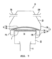
- FIG. 10 when an air cleaner case 101 is disposed between a pair of left and right frames 200, 200 and a seal section 103 for sealing an element 102 is disposed between the both frames 200, 200, the passage area of an air flow 300 that mainly flows vertically in the air cleaner case 101 becomes narrow within the seal section 103. In the case that the passage area of the air flow 300 in the air cleaner case 101 is small, a sufficient amount of intake air may not be supplied to an engine when, for example, the throttle is opened sharply.
- the present invention has been made in view of the above situation. It is an object of the invention to provide a sufficient amount of intake air to an engine in an motorcycle including an air cleaner having an air cleaner case disposed between a pair of left and right frames and an element disposed to divide at least a part of the inside of the air cleaner case into upper and lower spaces.
- a motorcycle comprising:
- the element may be formed in a plate shape.
- the element may be curved, and may be convex upward.
- the motorcycle may further comprise a fuel tank, wherein at least a part of the fuel tank may be positioned above at least part of the air cleaner case.
- At least a part of a portion of the air cleaner case positioned below the fuel tank may be profiled downward.
- the profile may be defined by a concave shape, a dented profile or the like.
- the motorcycle may further comprising a seat, wherein at least a part of the seat may be positioned above at least part of the fuel tank.
- the fuel tank may include a cap positioned above at least a part of the air cleaner case.
- the air cleaner case may include a dirty-side chamber positioned above the element and an intake duct forming an inflow passage that introduces intake air into the dirty-side chamber.
- the duct may be connected to the dirty-side chamber such that when the inflow passage is extended into the dirty-side chamber, the extended part of the inflow passage does not intersect with an upper surface of the element.
- the inflow passage of the intake duct may be arranged such that intake air is not focused directly towards an upper surface of the element.
- the air cleaner case may include a first case member having the upper section and the lower section and a second case member detachably attached to the first case member to cover the first case member from above.
- the first case member may be integrally formed.
- the upper section may protrude from the lower section above the left and right frame members, and may extend outward in the lateral direction.
- the motorcycle may be an off-road type.
- “divide into upper and lower spaces” includes not only dividing by a horizontal plane but also dividing by a plane tilting from a horizontal direction (in other words, obliquely dividing into upper and lower spaces).
- “Extending rearward from the head pipe in the side view” includes not only extending horizontally rearward from the head pipe in the side view but also extending in a direction tilted from the horizontal direction.
- the seal section for supporting the element is positioned above the left and the right frame members. Consequently, although a part (i.e. lower section) of the air cleaner case is disposed between the left and the right frame members, a relatively large flow passage area can be secured inside the seal section. Therefore, according to the above motorcycle, a sufficient amount of intake air to the engine can be secured.
- the seal section is positioned above the left and the right frame members. Accordingly, the width of the element can be made larger. Therefore, the surface area of the element can be increased. This also facilitates to secure a sufficient amount of intake air to the engine.
- an air cleaner having an air cleaner case disposed between a pair of left and right frames and an element disposed to divide at least a part of the inside of the air cleaner case into upper and lower spaces.
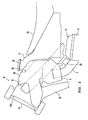
- FIG. 1 is a left side view of a motorcycle 20 according to this embodiment. With reference to FIG. 1 , a general construction of the motorcycle 20 will be described. In the following description, front, rear, left and right directions are those as viewed from a rider seated on a seat 18.
- the motorcycle 20 includes a body frame 16 forming a framework, and a seat 18 on which a rider is to be seated.
- the motorcycle 20 is a so-called off-road motorcycle.
- a motorcycle according to the present invention is not limited to this, but can be a motorcycle other than an off-road type (such as motorcycle type, scooter type, or so-called moped type motorcycle).
- the body frame 16 includes a head pipe 14, a down tube 25, and a main frame 15.
- the down tube 25 extends downward from a bracket 14a of the head pipe 14.
- the main frame 15 extends rearward from the bracket 14a of the head pipe 14 at a position above the down tube 25.
- the main frame 15 is constructed with a pair of left and right frame members 15L, 15R (see FIG. 4 ) that extend rearward from the bracket 14a of the head pipe 14. The main frame 15 extends more downward at its more rearward position.
- a pair of left and right seat rails 27 are connected to the main frame 15.
- the seat rails 27 extend rearward.
- a back stay 28 is connected to the main frame 15 at a position below a part to which the seat rail 27 is connected.
- a rear arm 29 is coupled to the lower ends of the main frame 15 with a pivot shaft 30 therebetween.
- the lower end of the head pipe 14 is connected to a front fork 31.
- a front wheel 32 is connected to the front fork 31 and a rear wheel 33 is connected to the rear end of the rear arm.
- a cover 24 is provided above the body frame 16 to cover the body frame 16.
- a fuel tank 17 extends between the main frame 15 and the back stay 28 above thereof.
- the seat 18 is disposed above the fuel tank 17. Specifically, as shown in FIG. 2 , a front portion of the seat 18 including at least its front end is positioned above the fuel tank 17. The front portion of the seat 18 including at least its front end is disposed to overlap a rear potion of the fuel tank 17 including at least its rear end as viewed from top.
- a power unit 35 is disposed between the down tube 25 and the main frame 15 to be attached thereto.
- the power unit 35 is integrally constituted by an engine 11 for generating driving force and a transmission.
- the power unit 35 is connected to the rear wheel 33 via a power transmission means 34 such as a chain. With this construction, driving force generated by the engine 11 is transmitted to the rear wheel 33 through the power transmission means 34.
- the engine 11 has a cylinder 9.
- the cylinder 9 protrudes obliquely upward and to the rear in the side view.
- the cylinder 9 may extend upward in the side view.
- the cylinder 9 may extend obliquely upward and forward in the side view.
- the engine 11 is a four-cycle or four-stroke single-cylinder engine.
- the engine 11 may be two-cycle or two-stroke engine or may have multiple cylinders.
- the cylinder 9 is connected to one end of an intake pipe 5.
- the intake pipe 5 extends obliquely upward from the cylinder 9 in the side view.
- the intake pipe 5 extends obliquely forward from the front side of the cylinder 9 in the side view.
- the other end of the intake pipe 5 is connected to an air cleaner case 3 of an air cleaner 10.
- the air cleaner 10 passes air to be supplied to the engine 11 to purify the air.
- the intake pipe 5 may extend generally horizontally forward from the front side of the cylinder 9.
- Reference numeral 38 denotes a fuel injection device or a carburetor disposed in the midway of the intake pipe 5 for supplying fuel into the intake pipe 5.
- an exhaust pipe 12 is connected to the cylinder 9.
- the exhaust pipe 12 extends obliquely rearward from the rear side of the cylinder 9 in the side view.
- the other end of the exhaust pipe 12 is connected to a muffler 36.
- the exhaust pipe 12 may alternatively extend generally horizontally rearward from the rear side of the cylinder 9.
- the intake pipe 5 extends forward or obliquely forward from the front side of the cylinder 9 while the exhaust pipe 12 extends obliquely rearward from the rear side of the cylinder 9.
- the motorcycle according to the present invention is not limited thereto.
- the motorcycle according to the present invention may be a motorcycle in which the intake pipe 5 extends rearward or obliquely rearward from the rear side of the cylinder 9 and the exhaust pipe 12 extends forward or obliquely forward from the front side of the cylinder 9.
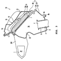
- FIG. 3 is a sectional view of the air cleaner 10 as viewed from the left side.
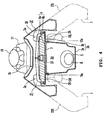
- FIG. 4 is a sectional view of the air cleaner 10 as viewed from the front side.
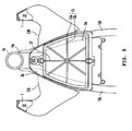
- FIG. 5 is an elevational view of the vicinity of the air cleaner 10 from above.
- the air cleaner 10 has the air cleaner case 3 and an element 6 disposed inside the air cleaner case 3.
- the element 6 is attached inside the air cleaner case 3.
- the air cleaner case 3 includes a first case member 3A, a second case member 3B, and two ducts 23L, 23R (see FIG. 4 ).
- the first case member 3A includes a lower section 3a and an upper section 3b. At least a part of the lower section 3a is interposed between the left and the right frame members 15L, 15R which form the main frame 15. In this embodiment, an upper part of the lower section 3a is interposed between the left and the right frame members 15L, 15R.
- the upper section 3b protrudes above the left and the right frame members 15L, 15R from the lower section 3a and extends outward in a lateral direction.
- the upper section 3b has a seal section 26 abutting on and supporting a main element 6a, which will be described later.
- the seal section 26 is positioned above the left and the right frame members 15L, 15R and at least a part of the seal section 26 is positioned more outside inner ends 15a of the left and the right frame members 15L, 15R.
- the second case member 3B covers the first case member 3A from above and is detachably attached to the first case member 3A.
- the first case member 3A and the second case member 3B form an inner space 3d in the air cleaner case 3 that temporarily reserves air and passes it toward the intake pipe 5.
- Two openings 3e are formed in the second case member 3B.
- the openings 3e are formed generally symmetrically in the lateral direction.
- the ducts 23L, 23R are respectively attached to the two openings 3e.
- the duct 23L disposed in the left side and the duct 23R disposed in the right side are formed in generally symmetrical shapes.
- the ducts 23L, 23R respectively extend outward in the lateral direction from the second case member 3B and then curve to further extend forward (see FIG. 5 ).
- Inlets 1 for introducing outside air into the ducts 23L, 23R are respectively formed at the front ends of the two ducts 23L, 23R.
- Inflow passages 3f for introducing the outside air to the inner space 3d are respectively formed in the two ducts 23L, 23R.
- the two openings 3e may not be formed in generally symmetrical positions in the lateral direction.
- the ducts 23L, 23R may not be formed in generally symmetrical shapes in the lateral direction.
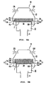
- the ducts 23L, 23R are connected to the second case member 3B in such a manner that when the inflow passages 3f are extended toward the inner space 3d side, the inflow passages 3f do not intersect with an upper surface of the element 6. Specifically, as shown in FIGs. 6 (a) and 6 (b) , the ducts 23L, 23R are connected to the second case member 3B so that extended portions 3g (portions within the air cleaner case 3) of the inflow passages 3f extend not to intersect with the upper surface of the main element 6a.
- the ducts 23L, 23R are connected to the second case member 3B in such a manner that when the inflow passages 3f are extended toward the inner space 3d side, the extended portions of the inflow passages 3f extend above the upper surface of the element 6.
- the ducts 23L, 23R may be connected, as shown in FIG. 6(a) , so that the extended portions 3g of the inflow passages 3f extend generally parallel with the upper surface of the main element 6a. Further, the ducts 23L, 23R may be connected, as shown in FIG. 6(b) , so that the extended portions 3g of the inflow passages 3f extend in a direction (obliquely upward) deviating from the upper surface of the main element 6a.
- the lower section 3a of the first case member 3A which forms a part of the inner space 3d has a bottom 8.
- An outlet 2 for ejecting air out of the inner space 3d is formed in the bottom 8.
- the intake pipe 5 is connected to the outlet 2.
- An intake opening 4 is formed in the intake pipe 5 to open upward or obliquely upward in the inner space 3d.
- the intake pipe 5 extends above the bottom 8 in the inner space 3d. Accordingly, the intake opening 4 is positioned above the bottom 8.
- the intake pipe 5 may be connected to the bottom 8 of the air cleaner case 3 so that the intake opening 4 is generally flush with the bottom 8 of the air cleaner case 3. In this case, the intake opening 4 opens upward or obliquely upward toward the inner space 3d.
- a drainage section 8a is formed for discharging water when the water by the rainfall or the like collects on the bottom 8.
- the drainage section 8a is closed by a lid 8b. With such a construction, dust is prevented from entering through the drainage section 8a into a clean-side chamber 22, which will be described later.
- the drainage section 8a may alternatively be closed by a sponge or the like instead of the lid 8b. Also, the drainage section 8a may be provided with a backflow prevention device without the lid 8b.
- At least a part of the air cleaner case 3 is disposed below the fuel tank 17. More specifically, a part of the rear side of the air cleaner case 3 is positioned below a part of the front side of the fuel tank 17. As shown in FIGs. 2 and 4 , at least a portion 3c of the air cleaner case 3, which is the part positioned below the fuel tank 17, is profiled, dented or formed downward, or is concave. Accordingly, at least a part of the fuel tank 17 is positioned over the portion 3c of the air cleaner case 3, which is dented downward. As shown in FIG. 2 , the fuel tank 17 is provided with a cap 19 to cover a filler (not shown) opening upward. The cap 19 is positioned above the portion 3c of the air cleaner case 3, which is dented downward.
- the element 6 is formed in a plate shape.
- the element 6 includes a main element 6a and an auxiliary element 6b, which is separate from the main element 6a. Both the main element 6a and the auxiliary element 6b are disposed in the inner space 3d.
- the element 6 divides the inner space 3d, which is at least a part of the inside of the air cleaner case 3, into upper and lower spaces. More specifically, the element 6 divides the inner space 3d into a dirty-side chamber 21 positioned above the main element 6a and a clean-side chamber 22 positioned below the auxiliary element 6b.
- the main element 6a is disposed above the intake opening 4.
- the main element 6a is supported by the seal section 26 of the upper section 3b of the first case member 3A and thereby sealed around its circumference.
- the auxiliary element 6b is attached to the upper section 3b so as to be positioned above the intake opening 4 and below the main element 6a.
- the main element 6a is constructed to be detachable from the upper section 3b with the auxiliary element 6b remaining attached to the upper section 3b.
- the main element 6a is constructed to be detachable from the upper section 3b with the auxiliary element 6b remaining attached in the inner space 3d.
- the main element 6a has a finer element than the auxiliary element 6b has.
- the auxiliary element 6b has a coarser element than the main element 6a has.
- the main element 6a and the auxiliary element 6b may have an element of the same fineness.
- the main element 6a may have a coarser element than the auxiliary element 6b has.
- a pressing member 13 is disposed above the main element 6a.
- the pressing member 13 presses the main element 6a downward or obliquely downward.
- the pressing member 13 includes a frame 13a in a generally trapezoidal shape and six ribs 13b radially extending from the center of the frame 13a.
- the pressing member 13 is fixed by a detachable fixing member 37. In FIG. 3 , the fixing member 37 is not shown.
- a flameproof net 7 is disposed under the auxiliary element 6b.
- the flameproof net 7 extinguishes any flames caused by a backfire (backfire is a phenomenon in which mixture gas to be combusted in the cylinder 9 flows back to the intake pipe 5 and so forth) from the engine 11 and thereby prevents the element 6 from being burned by the flames.
- backfire is a phenomenon in which mixture gas to be combusted in the cylinder 9 flows back to the intake pipe 5 and so forth
- the element 6 includes the main element 6a and the auxiliary element 6b, which has a coarser element than the main element 6a has. Accordingly, dust so sized as to be captured by the auxiliary element 6b is mostly captured by the main element 6a. As a result, the auxiliary element 6b has less dirt. Therefore, it is possible in the air cleaner 10 to recover the reduced purification performance by replacing, washing or cleaning only the main element 6a when the element 6 is subjected to replacement, washing or cleaning.
- the maintenance work (replacement, washing or cleaning) of the main element 6a will be described bellow.
- the second case member 3B is detached from the first case member 3A.
- the fixing member 37 for fixing the pressing member 13 is disengaged and the pressing member 13 is detached.
- the main element 6a is detached from the seal section 26 of the upper section 3b in the first case member 3A. It should be noted that the main element 6a is placed on the seal section 26. Accordingly, the main element 6a can be readily detached by lifting the main element 6a.
- the main element 6a is constructed to be detached from the upper section 3b in the first case member 3A, with the auxiliary element 6b being fixed in the inner space 3d. Accordingly, the auxiliary element 6b remains fixed in the inner space 3d after detaching the main element 6a.
- the auxiliary element 6b As described above, in the state that the auxiliary element 6b remains fixed in the inner space 3d, a replacement of the main element 6a is then placed on the seal section 26 of the upper section 3b. Or, after washing or cleaning the detached main element 6a, the washed or cleaned main element 6a is replaced on the seal section 26 of the upper section 3b. Following the reverse procedure to that described above, the pressing member 13 and the fixing member 37 are attached. Finally, the second case member 3B to which the ducts 23L, 23R are attached is assembled so as to cover the first case member 3A from above. With the above procedure, it is possible to recover the purification performance of the element 6 by replacing, washing or cleaning the main element 6a. Thus, the maintenance work of the air cleaner 10 is completed.
- the seal section 26 for supporting the main element 6a is positioned above the pair of the left and the right frame members 15L, 15R. Consequently, although a part (i.e. lower section 3a) of the air cleaner case 3 is disposed between the left and the right frame members 15L, 15R, a relatively large area of inflow passage can be secured inside the seal section 26. Therefore, according to the motorcycle 20, a sufficient amount of intake air to the engine 11 can be secured.
- the seal section 26 is positioned above the left and the right frame members 15L, 15R. Consequently, the width of the main element 6a can be made large. Accordingly, the surface area of the main element 6a can be increased. This also facilitates to secure a sufficient amount of intake air to the engine 11.
- the element 6 of the air cleaner 10 is formed in a plate shape. Accordingly, in comparison with the construction in which the seal section 26 is disposed between the left and the right frame members 15L, 15R, a larger surface area of the element 6 can be secured. As a result, even if the element 6 is formed in a plate shape as in this embodiment, a sufficient surface area can be secured.
- the element 6 since the element 6 is in a plate shape, the element 6 does not protrude upward, which makes the vertical length of the air cleaner case 3 relatively short.
- the motorcycle 20 includes the fuel tank 17, at least a part of which is positioned above the air cleaner case 3. In other words, at least a part of the fuel tank 17 and at least a part of the air cleaner case 3 overlap vertically. Nevertheless, according to the motorcycle 20 described above, a large surface area can be secured for the element 6 without largely protruding the element 6 upward. Consequently, the heights (vertical length) of the element 6 and the air cleaner case 3 can be reduced. Therefore, according to the motorcycle 20, even though the fuel tank 17 and the air cleaner case 3 overlap vertically, the fuel tank 17 can be prevented from largely protruding upward. In addition, according to the motorcycle 20, the height of an upper face of the fuel tank 17 can be reduced while a relatively large capacity of the fuel tank 17 is secured.
- the portion 3c of the air cleaner case 3, which is the part positioned below the fuel tank 17, is dented, profiled or formed downward, or is concave. Accordingly, at least a part of the fuel tank 17 is positioned over the portion 3c of the air cleaner case 3, which is dented downward. Therefore, according to the motorcycle 20, although the fuel tank 17 and the air cleaner case 3 overlap vertically, the fuel tank 17 can be prevented from largely protruding upward. In addition, according to the motorcycle 20, the height of an upper face of the fuel tank 17 can be further reduced while a relatively large capacity of the fuel tank 17 is secured.
- the seat 18 is disposed above the fuel tank 17. Specifically, a front portion of the seat 18 including its front end is positioned above the fuel tank 17. As described above, in the motorcycle 20, the height (vertical length) of the air cleaner case 3 can be reduced. Therefore, according to the motorcycle 20, although the air cleaner case 3 and the fuel tank 17 overlap vertically and the fuel tank 17 and the seat 18 overlap vertically, the vehicle height (vertical length from the ground to the seat 18) can be reduced.
- the fuel tank 17 includes the cap 19.
- the cap 19 when the cap 19 is disposed on an upper part of the fuel tank 17, the height of the fuel tank 17 is increased by the thickness of the cap 19.
- the cap 19 is positioned above the portion 3c of the air cleaner case 3, which is dented downward. Accordingly, even though the cap 19 is disposed on an upper part of the fuel tank 17, the height of the fuel tank 17 can be reduced while a relatively large capacity of the fuel tank 17 is secured.
- the air cleaner 10 of the motorcycle 20 is constructed such that the air supplied to the dirty-side chamber 21 does not directly hit the element 6.
- the element 6 can be utilized uniformly and thereby prevented from being intensively soiled or being clogged.
- the air cleaner 10 according to the invention is especially suitable for the off-road motorcycle 20 of this embodiment.
- the rider may operate a motorcycle with his/her hip lifted without being seated on the seat 18. Due to this, in the off-road motorcycle, the distance between the left and the right frame members 15L, 15R, which are located between the rider's legs, is narrowed as much as possible to allow the rider to easily lift his/her hip. Accordingly, in the off-road motorcycle 20, although a part (i.e. lower section 3a) of the air cleaner case 3 is disposed between the left and the right frame members 15L, 15R, the effect that a relatively large area of inflow passage can be secured inside the seal section 26 is remarkably achieved.
- a motorcycle 20 according to a second embodiment is constructed such that a main element 6a having a larger area than the main element 6a in the first embodiment is curved to be convex upward.
- Other constitution than the above is similar to the first embodiment and the description thereof will be omitted.
- the main element 6a having a large area is curved to be convex upward. Therefore, a large surface area of the main element 6a can be secured without widening the air cleaner case 3.
- the vertical length of the air cleaner case 3 can be reduced in comparison with a conventional air cleaner in which an element is formed in a bowl shape.
- contradictory objects can be attained at the same time: a sufficient amount of intake air to the engine 11 is secured by securing a relatively large flow passage area while the vertical length of the air cleaner case 3 is reduced.
- the main element 6a is curved to be convex upward.
- the main element 6a may be curved to be convex downward. In this configuration also, the same effect as above can be achieved. Further, the main element 6a may be curved to be convex upward in a bowl shape.
- the main element 6a is disposed in a curved manner.
- the auxiliary element 6b and the flameproof net 7 may be disposed in a curved manner.
- the first case member 3A is constructed by the lower section 3a and the upper section 3b, which are separate from each other.
- the first case member 3A may be integrally formed. According to the thus configured motorcycle 20, the first case member 3A of the air cleaner 10 can be formed in one piece. Therefore, it is possible to reduce the number of parts.
- the main element 6a is configured by a single element member (single-layered configuration).
- the main element 6a may be multi-layered.
- the main element 6a may be double-layered in which a first element 6c and a second element 6d having a finer element than the first element 6c has are provided.
- the main element 6a may be triple-layered in which a first element 6c, a second element 6d having a finer element than the first element 6c has, and a third element 6e having a finer element than the second element 6d has are provided.
- the main element 6a may have more layers.
- the element is configured such that a plurality of elements are layered so that a downstream side element has a finer element. This improves air purification performance.
- elements constituting the respective layers can be integrally replaced.
- the present invention is useful for a motorcycle.
Landscapes
- Engineering & Computer Science (AREA)
- Mechanical Engineering (AREA)
- Chemical & Material Sciences (AREA)
- Combustion & Propulsion (AREA)
- General Engineering & Computer Science (AREA)
- Automatic Cycles, And Cycles In General (AREA)
Claims (13)
- Motocyclette (20), comprenant :un cadre de carrosserie (16), comportant un tube de direction (14) et des éléments de cadre de gauche et de droite (15L, 15R), s'étendant vers l'arrière à partir du tube de direction (15) ; etun filtre à air (10), comportant un boîtier du filtre à air (3) et un élément (6) agencé à l'intérieur du boîtier du filtre à air (3) pour purifier l'air devant être amené vers un moteur (11), le boîtier du filtre à air (6) englobant :une section inférieure (3a), au moins une partie de cette section inférieure (3a) étant agencée entre les éléments de cadre de droite et de gauche (15L, 15R) ; etune section supérieure (3b), comportant une section d'étanchéité (26) agencée au-dessus des éléments de cadre (15L, 15R), au moins une partie de la section d'étanchéité (26) étant positionnée vers l'extérieur des extrémités internes des éléments de cadre de gauche et de droite (15L, 15R), dans une direction latérale ;l'élément (6) étant supporté et son étanchéité étant établie par la section d'étanchéité (26), et divisant au moins une partie de l'intérieur du boîtier du filtre à air (3) en des espaces supérieur et inférieur (21, 22).
- Motocyclette (20) selon la revendication 1, dans laquelle l'élément (6) a une forme en plaque.
- Motocyclette (20) selon les revendications 1 ou 2, dans laquelle l'élément (6) est courbé pour être convexe vers le haut.
- Motocyclette (20) selon les revendications 1, 2 ou 3, comprenant en outre un réservoir d'essence (17), au moins une partie du réservoir d'essence (17) étant positionnée au-dessus d'au moins une partie du boîtier du filtre à air (3).
- Motocyclette (20) selon la revendication 4, dans laquelle au moins une partie d'une partie du boîtier du filtre à air (3) positionné au-dessous du réservoir de carburant (17) est profilée vers le bas.
- Motocyclette (20) selon les revendications 4 ou 5, comprenant en outre un siège (18), au moins une partie du siège (18) étant positionnée au-dessus d'au moins une partie du réservoir d'essence (17).
- Motocyclette (20) selon les revendications 4, 5 ou 6, dans laquelle le réservoir d'essence (17) englobe un bouchon (19) positionné au-dessus d'au moins une partie du boîtier du filtre à air (3).
- Motocyclette (20) selon l'une quelconque des revendications précédentes, dans laquelle le boîtier du filtre à air (3) englobe une chambre du côté sale (21) positionnée au-dessus de l'élément (3), et un conduit d'admission (23L, 23R) formant un passage d'entrée introduisant l'air d'admission dans la chambre du côté sale (21).
- Motocyclette (20) selon la revendication 8, dans laquelle le conduit (23L, 23R) est connecté à la chambre du côté sale (21), de sorte que lorsque le passage d'entrée est étendu dans la chambre du côté sale (21), une partie d'extension (3g) du passage d'entrée ne coupe pas une surface supérieure de l'élément (6).
- Motocyclette (20) selon les revendications 8 ou 9, dans laquelle le passage d'entrée du conduit d'admission (23L, 23R) est agencé de sorte que l'air d'admission n'est pas focalisé directement vers une surface supérieure de l'élément (6).
- Motocyclette (20) selon l'une quelconque des revendications précédentes, dans laquelle le boîtier du filtre à air (3) englobe un premier élément de boîtier (3A) comportant la section supérieure (3b) et la section inférieure (3a), et un deuxième élément de boîtier (3B), fixé de manière détachable sur le premier élément de boîtier (3A) pour recouvrir le premier élément de boîtier d'en haut, le premier élément de boîtier (3A) étant formé d'une seule pièce.
- Motocyclette (20) selon l'une quelconque des revendications précédentes, dans laquelle la section supérieure (3b) déborde de la section inférieure (3a) au-dessus des éléments de cadre de gauche et de droite (15L, 15R), et s'étend vers l'extérieur dans la direction latérale.
- Motocyclette (20) selon l'une quelconque des revendications précédentes, la motocyclette (20) étant du type tout-terrain.
Applications Claiming Priority (1)
| Application Number | Priority Date | Filing Date | Title |
|---|---|---|---|
| JP2007259648A JP2009083810A (ja) | 2007-10-03 | 2007-10-03 | 自動二輪車 |
Publications (3)
| Publication Number | Publication Date |
|---|---|
| EP2045461A2 EP2045461A2 (fr) | 2009-04-08 |
| EP2045461A3 EP2045461A3 (fr) | 2011-03-02 |
| EP2045461B1 true EP2045461B1 (fr) | 2011-12-21 |
Family
ID=40251641
Family Applications (1)
| Application Number | Title | Priority Date | Filing Date |
|---|---|---|---|
| EP08253197A Not-in-force EP2045461B1 (fr) | 2007-10-03 | 2008-10-01 | Motocyclette |
Country Status (4)
| Country | Link |
|---|---|
| US (1) | US7942226B2 (fr) |
| EP (1) | EP2045461B1 (fr) |
| JP (1) | JP2009083810A (fr) |
| AT (1) | ATE538301T1 (fr) |
Cited By (1)
| Publication number | Priority date | Publication date | Assignee | Title |
|---|---|---|---|---|
| CN110520351A (zh) * | 2017-03-10 | 2019-11-29 | 印度摩托车国际有限公司 | 两轮式车辆 |
Families Citing this family (22)
| Publication number | Priority date | Publication date | Assignee | Title |
|---|---|---|---|---|
| EP1927792B1 (fr) * | 2006-11-29 | 2010-02-17 | Yamaha Hatsudoki Kabushiki Kaisha | Motocyle |
| JP2009085195A (ja) * | 2007-10-03 | 2009-04-23 | Yamaha Motor Co Ltd | 車両用エアクリーナおよびそれを備えた自動二輪車 |
| DE102008061123B4 (de) * | 2007-12-30 | 2017-06-01 | Honda Motor Co., Ltd. | Motorrad |
| JP2009202827A (ja) * | 2008-02-29 | 2009-09-10 | Yamaha Motor Co Ltd | 自動二輪車 |
| JP5210764B2 (ja) * | 2008-08-27 | 2013-06-12 | 本田技研工業株式会社 | 自動二輪車のシートレール |
| SMT201700045T1 (it) * | 2009-07-17 | 2017-03-08 | Nektar Therapeutics | Sistemi e metodi per azionare nebulizzatori sigillati |
| JP5656430B2 (ja) * | 2010-03-23 | 2015-01-21 | 本田技研工業株式会社 | エアクリーナ装置 |
| JP2012111278A (ja) * | 2010-11-22 | 2012-06-14 | Yamaha Motor Co Ltd | 自動二輪車 |
| JP5772149B2 (ja) * | 2011-03-30 | 2015-09-02 | スズキ株式会社 | 自動二輪車 |
| JP5849346B2 (ja) * | 2012-03-16 | 2016-01-27 | 本田技研工業株式会社 | 鞍乗り型車両における吸気装置 |
| JP5925547B2 (ja) * | 2012-03-22 | 2016-05-25 | 本田技研工業株式会社 | 鞍乗り型車両の導風構造 |
| USD684506S1 (en) * | 2012-05-09 | 2013-06-18 | Kawasaki Jukogyo Kabushiki Kaisha | Side cover for motorcycles |
| JP6068101B2 (ja) * | 2012-11-13 | 2017-01-25 | 本田技研工業株式会社 | 鞍乗型車両 |
| CN108100128B (zh) | 2013-03-15 | 2020-08-21 | 北极星工业有限公司 | 两轮车辆 |
| JP6191249B2 (ja) * | 2013-06-06 | 2017-09-06 | スズキ株式会社 | 自動二輪車のエアクリーナ構造 |
| JP5852071B2 (ja) * | 2013-09-26 | 2016-02-03 | 本田技研工業株式会社 | 鞍乗り型車両の吸気構造 |
| US9714631B2 (en) | 2015-12-11 | 2017-07-25 | Honda Motor Co., Ltd. | Air intake structure of straddle type vehicle |
| JP2018086908A (ja) * | 2016-11-28 | 2018-06-07 | ヤマハ発動機株式会社 | 鞍乗型車両 |
| DE102017220119A1 (de) * | 2017-11-13 | 2019-05-16 | Bayerische Motoren Werke Aktiengesellschaft | Sitzbankanordnung für ein Motorrad |
| USD911879S1 (en) | 2018-09-10 | 2021-03-02 | Indian Motorcycle International, LLC | Motorcycle |
| US11077910B2 (en) | 2018-09-28 | 2021-08-03 | Indian Motorcycle International, LLC | Two-wheeled vehicle |
| US11408325B2 (en) * | 2019-01-18 | 2022-08-09 | Briggs & Stratton, Llc | V-Twin engine assembly |
Family Cites Families (11)
| Publication number | Priority date | Publication date | Assignee | Title |
|---|---|---|---|---|
| US4799569A (en) * | 1985-08-23 | 1989-01-24 | Honda Giken Kogyo Kabushiki Kaisha | Motorcycle |
| JPS63145189A (ja) | 1986-12-09 | 1988-06-17 | スズキ株式会社 | オ−トバイのエンジン塔載装置 |
| JPS63166674A (ja) * | 1986-12-27 | 1988-07-09 | 本田技研工業株式会社 | 自動二輪車のエアクリ−ナ装置 |
| JP3701716B2 (ja) | 1995-10-31 | 2005-10-05 | ヤマハ発動機株式会社 | 自動二輪車 |
| JP2001106151A (ja) * | 1999-10-13 | 2001-04-17 | Honda Motor Co Ltd | 自動二輪車 |
| JP3911950B2 (ja) * | 2000-02-25 | 2007-05-09 | スズキ株式会社 | 自動二輪車 |
| US7059438B1 (en) * | 2002-08-01 | 2006-06-13 | Sheets Wilbert J | ATV with an improved transmission and air intake |
| JP4523375B2 (ja) * | 2004-09-30 | 2010-08-11 | 本田技研工業株式会社 | 自動二輪車のエアクリーナ |
| JP4629526B2 (ja) * | 2005-07-27 | 2011-02-09 | 本田技研工業株式会社 | 自動二輪車のエアクリーナ |
| JP4609941B2 (ja) * | 2005-09-07 | 2011-01-12 | 本田技研工業株式会社 | エアバッグモジュール取付構造 |
| US7766119B2 (en) * | 2007-02-01 | 2010-08-03 | Yamaha Hatsudoki Kabushiki Kaisha | Vehicle |
-
2007
- 2007-10-03 JP JP2007259648A patent/JP2009083810A/ja active Pending
-
2008
- 2008-10-01 AT AT08253197T patent/ATE538301T1/de active
- 2008-10-01 EP EP08253197A patent/EP2045461B1/fr not_active Not-in-force
- 2008-10-02 US US12/244,347 patent/US7942226B2/en not_active Expired - Fee Related
Cited By (1)
| Publication number | Priority date | Publication date | Assignee | Title |
|---|---|---|---|---|
| CN110520351A (zh) * | 2017-03-10 | 2019-11-29 | 印度摩托车国际有限公司 | 两轮式车辆 |
Also Published As
| Publication number | Publication date |
|---|---|
| ATE538301T1 (de) | 2012-01-15 |
| US20090090576A1 (en) | 2009-04-09 |
| US7942226B2 (en) | 2011-05-17 |
| EP2045461A3 (fr) | 2011-03-02 |
| EP2045461A2 (fr) | 2009-04-08 |
| JP2009083810A (ja) | 2009-04-23 |
Similar Documents
| Publication | Publication Date | Title |
|---|---|---|
| EP2045461B1 (fr) | Motocyclette | |
| EP2045462B1 (fr) | Filtre à air et véhicule doté de celui-ci | |
| JP4108290B2 (ja) | 車両の後部構造 | |
| JP2009202827A (ja) | 自動二輪車 | |
| JP2014051148A (ja) | 鞍乗り型車両のキャニスタ配置構造 | |
| JP4015475B2 (ja) | エンジンのブローバイガス処理装置 | |
| AU2013207656B2 (en) | Air cleaner case structure for straddle type vehicle | |
| JP6408591B2 (ja) | 鞍乗型車両 | |
| JP4052873B2 (ja) | スクータ型車両 | |
| JP2014196672A (ja) | 車両用内燃機関の吸気装置 | |
| JP3142128U (ja) | 内燃機関のブリーザ構造およびそれを備えた車両 | |
| JP4283002B2 (ja) | エンジンの吸気装置 | |
| JP2010167796A (ja) | 鞍乗型車両 | |
| JP3157335U (ja) | 自動二輪車 | |
| JP2012197744A (ja) | 自動二輪車における蒸発燃料処理装置 | |
| JP3157334U (ja) | 車両用エアクリーナおよびそれを備えた自動二輪車 | |
| JP2007008357A (ja) | 自動二輪車の空気吸入構造 | |
| JP3470388B2 (ja) | 自動二輪車のエアクリーナ | |
| JP4592017B2 (ja) | 自動2輪車用エアクリーナ装置 | |
| JP6083601B2 (ja) | 鞍乗り型車両におけるエアクリーナ構造 | |
| JP6523027B2 (ja) | 小型車両用内燃機関の吸気装置 | |
| JP2013189172A (ja) | 鞍乗型車両の吸気構造 | |
| JP3141710B2 (ja) | 自動二輪車用エンジンのエアクリーナ構造 | |
| JP2008207694A (ja) | 車両の吸気通路構造 | |
| JP4801814B2 (ja) | 車両用無段変速機の冷却構造 |
Legal Events
| Date | Code | Title | Description |
|---|---|---|---|
| PUAI | Public reference made under article 153(3) epc to a published international application that has entered the european phase |
Free format text: ORIGINAL CODE: 0009012 |
|
| 17P | Request for examination filed |
Effective date: 20081006 |
|
| AK | Designated contracting states |
Kind code of ref document: A2 Designated state(s): AT BE BG CH CY CZ DE DK EE ES FI FR GB GR HR HU IE IS IT LI LT LU LV MC MT NL NO PL PT RO SE SI SK TR |
|
| AX | Request for extension of the european patent |
Extension state: AL BA MK RS |
|
| PUAL | Search report despatched |
Free format text: ORIGINAL CODE: 0009013 |
|
| AK | Designated contracting states |
Kind code of ref document: A3 Designated state(s): AT BE BG CH CY CZ DE DK EE ES FI FR GB GR HR HU IE IS IT LI LT LU LV MC MT NL NO PL PT RO SE SI SK TR |
|
| AX | Request for extension of the european patent |
Extension state: AL BA MK RS |
|
| RIC1 | Information provided on ipc code assigned before grant |
Ipc: B60K 13/02 20060101ALI20110126BHEP Ipc: F02M 35/16 20060101ALI20110126BHEP Ipc: F02M 35/04 20060101ALI20110126BHEP Ipc: F02M 35/024 20060101AFI20090126BHEP Ipc: B62K 11/04 20060101ALI20110126BHEP |
|
| GRAP | Despatch of communication of intention to grant a patent |
Free format text: ORIGINAL CODE: EPIDOSNIGR1 |
|
| RIC1 | Information provided on ipc code assigned before grant |
Ipc: F02M 35/024 20060101AFI20110415BHEP Ipc: F02M 35/16 20060101ALI20110415BHEP Ipc: F02M 35/04 20060101ALI20110415BHEP Ipc: B62K 11/04 20060101ALI20110415BHEP Ipc: B60K 13/02 20060101ALI20110415BHEP |
|
| GRAS | Grant fee paid |
Free format text: ORIGINAL CODE: EPIDOSNIGR3 |
|
| AKX | Designation fees paid |
Designated state(s): AT BE BG CH CY CZ DE DK EE ES FI FR GB GR HR HU IE IS IT LI LT LU LV MC MT NL NO PL PT RO SE SI SK TR |
|
| GRAA | (expected) grant |
Free format text: ORIGINAL CODE: 0009210 |
|
| AK | Designated contracting states |
Kind code of ref document: B1 Designated state(s): AT BE BG CH CY CZ DE DK EE ES FI FR GB GR HR HU IE IS IT LI LT LU LV MC MT NL NO PL PT RO SE SI SK TR |
|
| REG | Reference to a national code |
Ref country code: GB Ref legal event code: FG4D |
|
| REG | Reference to a national code |
Ref country code: CH Ref legal event code: EP |
|
| REG | Reference to a national code |
Ref country code: AT Ref legal event code: REF Ref document number: 538301 Country of ref document: AT Kind code of ref document: T Effective date: 20120115 |
|
| REG | Reference to a national code |
Ref country code: IE Ref legal event code: FG4D |
|
| REG | Reference to a national code |
Ref country code: DE Ref legal event code: R096 Ref document number: 602008012142 Country of ref document: DE Effective date: 20120301 |
|
| REG | Reference to a national code |
Ref country code: NL Ref legal event code: VDEP Effective date: 20111221 |
|
| PG25 | Lapsed in a contracting state [announced via postgrant information from national office to epo] |
Ref country code: NO Free format text: LAPSE BECAUSE OF FAILURE TO SUBMIT A TRANSLATION OF THE DESCRIPTION OR TO PAY THE FEE WITHIN THE PRESCRIBED TIME-LIMIT Effective date: 20120321 Ref country code: LT Free format text: LAPSE BECAUSE OF FAILURE TO SUBMIT A TRANSLATION OF THE DESCRIPTION OR TO PAY THE FEE WITHIN THE PRESCRIBED TIME-LIMIT Effective date: 20111221 |
|
| LTIE | Lt: invalidation of european patent or patent extension |
Effective date: 20111221 |
|
| PG25 | Lapsed in a contracting state [announced via postgrant information from national office to epo] |
Ref country code: SE Free format text: LAPSE BECAUSE OF FAILURE TO SUBMIT A TRANSLATION OF THE DESCRIPTION OR TO PAY THE FEE WITHIN THE PRESCRIBED TIME-LIMIT Effective date: 20111221 Ref country code: LV Free format text: LAPSE BECAUSE OF FAILURE TO SUBMIT A TRANSLATION OF THE DESCRIPTION OR TO PAY THE FEE WITHIN THE PRESCRIBED TIME-LIMIT Effective date: 20111221 Ref country code: SI Free format text: LAPSE BECAUSE OF FAILURE TO SUBMIT A TRANSLATION OF THE DESCRIPTION OR TO PAY THE FEE WITHIN THE PRESCRIBED TIME-LIMIT Effective date: 20111221 Ref country code: HR Free format text: LAPSE BECAUSE OF FAILURE TO SUBMIT A TRANSLATION OF THE DESCRIPTION OR TO PAY THE FEE WITHIN THE PRESCRIBED TIME-LIMIT Effective date: 20111221 Ref country code: GR Free format text: LAPSE BECAUSE OF FAILURE TO SUBMIT A TRANSLATION OF THE DESCRIPTION OR TO PAY THE FEE WITHIN THE PRESCRIBED TIME-LIMIT Effective date: 20120322 Ref country code: NL Free format text: LAPSE BECAUSE OF FAILURE TO SUBMIT A TRANSLATION OF THE DESCRIPTION OR TO PAY THE FEE WITHIN THE PRESCRIBED TIME-LIMIT Effective date: 20111221 |
|
| PG25 | Lapsed in a contracting state [announced via postgrant information from national office to epo] |
Ref country code: CY Free format text: LAPSE BECAUSE OF FAILURE TO SUBMIT A TRANSLATION OF THE DESCRIPTION OR TO PAY THE FEE WITHIN THE PRESCRIBED TIME-LIMIT Effective date: 20111221 Ref country code: BE Free format text: LAPSE BECAUSE OF FAILURE TO SUBMIT A TRANSLATION OF THE DESCRIPTION OR TO PAY THE FEE WITHIN THE PRESCRIBED TIME-LIMIT Effective date: 20111221 |
|
| PG25 | Lapsed in a contracting state [announced via postgrant information from national office to epo] |
Ref country code: BG Free format text: LAPSE BECAUSE OF FAILURE TO SUBMIT A TRANSLATION OF THE DESCRIPTION OR TO PAY THE FEE WITHIN THE PRESCRIBED TIME-LIMIT Effective date: 20120321 Ref country code: IS Free format text: LAPSE BECAUSE OF FAILURE TO SUBMIT A TRANSLATION OF THE DESCRIPTION OR TO PAY THE FEE WITHIN THE PRESCRIBED TIME-LIMIT Effective date: 20120421 Ref country code: SK Free format text: LAPSE BECAUSE OF FAILURE TO SUBMIT A TRANSLATION OF THE DESCRIPTION OR TO PAY THE FEE WITHIN THE PRESCRIBED TIME-LIMIT Effective date: 20111221 Ref country code: EE Free format text: LAPSE BECAUSE OF FAILURE TO SUBMIT A TRANSLATION OF THE DESCRIPTION OR TO PAY THE FEE WITHIN THE PRESCRIBED TIME-LIMIT Effective date: 20111221 Ref country code: CZ Free format text: LAPSE BECAUSE OF FAILURE TO SUBMIT A TRANSLATION OF THE DESCRIPTION OR TO PAY THE FEE WITHIN THE PRESCRIBED TIME-LIMIT Effective date: 20111221 |
|
| PG25 | Lapsed in a contracting state [announced via postgrant information from national office to epo] |
Ref country code: RO Free format text: LAPSE BECAUSE OF FAILURE TO SUBMIT A TRANSLATION OF THE DESCRIPTION OR TO PAY THE FEE WITHIN THE PRESCRIBED TIME-LIMIT Effective date: 20111221 Ref country code: PT Free format text: LAPSE BECAUSE OF FAILURE TO SUBMIT A TRANSLATION OF THE DESCRIPTION OR TO PAY THE FEE WITHIN THE PRESCRIBED TIME-LIMIT Effective date: 20120423 Ref country code: PL Free format text: LAPSE BECAUSE OF FAILURE TO SUBMIT A TRANSLATION OF THE DESCRIPTION OR TO PAY THE FEE WITHIN THE PRESCRIBED TIME-LIMIT Effective date: 20111221 |
|
| REG | Reference to a national code |
Ref country code: AT Ref legal event code: MK05 Ref document number: 538301 Country of ref document: AT Kind code of ref document: T Effective date: 20111221 |
|
| PLBE | No opposition filed within time limit |
Free format text: ORIGINAL CODE: 0009261 |
|
| STAA | Information on the status of an ep patent application or granted ep patent |
Free format text: STATUS: NO OPPOSITION FILED WITHIN TIME LIMIT |
|
| PG25 | Lapsed in a contracting state [announced via postgrant information from national office to epo] |
Ref country code: DK Free format text: LAPSE BECAUSE OF FAILURE TO SUBMIT A TRANSLATION OF THE DESCRIPTION OR TO PAY THE FEE WITHIN THE PRESCRIBED TIME-LIMIT Effective date: 20111221 |
|
| 26N | No opposition filed |
Effective date: 20120924 |
|
| PG25 | Lapsed in a contracting state [announced via postgrant information from national office to epo] |
Ref country code: IT Free format text: LAPSE BECAUSE OF FAILURE TO SUBMIT A TRANSLATION OF THE DESCRIPTION OR TO PAY THE FEE WITHIN THE PRESCRIBED TIME-LIMIT Effective date: 20111221 |
|
| REG | Reference to a national code |
Ref country code: DE Ref legal event code: R097 Ref document number: 602008012142 Country of ref document: DE Effective date: 20120924 |
|
| PG25 | Lapsed in a contracting state [announced via postgrant information from national office to epo] |
Ref country code: AT Free format text: LAPSE BECAUSE OF FAILURE TO SUBMIT A TRANSLATION OF THE DESCRIPTION OR TO PAY THE FEE WITHIN THE PRESCRIBED TIME-LIMIT Effective date: 20111221 |
|
| PG25 | Lapsed in a contracting state [announced via postgrant information from national office to epo] |
Ref country code: ES Free format text: LAPSE BECAUSE OF FAILURE TO SUBMIT A TRANSLATION OF THE DESCRIPTION OR TO PAY THE FEE WITHIN THE PRESCRIBED TIME-LIMIT Effective date: 20120401 |
|
| PG25 | Lapsed in a contracting state [announced via postgrant information from national office to epo] |
Ref country code: MC Free format text: LAPSE BECAUSE OF NON-PAYMENT OF DUE FEES Effective date: 20121031 |
|
| REG | Reference to a national code |
Ref country code: CH Ref legal event code: PL |
|
| PG25 | Lapsed in a contracting state [announced via postgrant information from national office to epo] |
Ref country code: FI Free format text: LAPSE BECAUSE OF FAILURE TO SUBMIT A TRANSLATION OF THE DESCRIPTION OR TO PAY THE FEE WITHIN THE PRESCRIBED TIME-LIMIT Effective date: 20111221 |
|
| REG | Reference to a national code |
Ref country code: IE Ref legal event code: MM4A |
|
| PG25 | Lapsed in a contracting state [announced via postgrant information from national office to epo] |
Ref country code: LI Free format text: LAPSE BECAUSE OF NON-PAYMENT OF DUE FEES Effective date: 20121031 Ref country code: IE Free format text: LAPSE BECAUSE OF NON-PAYMENT OF DUE FEES Effective date: 20121001 Ref country code: CH Free format text: LAPSE BECAUSE OF NON-PAYMENT OF DUE FEES Effective date: 20121031 |
|
| PG25 | Lapsed in a contracting state [announced via postgrant information from national office to epo] |
Ref country code: MT Free format text: LAPSE BECAUSE OF FAILURE TO SUBMIT A TRANSLATION OF THE DESCRIPTION OR TO PAY THE FEE WITHIN THE PRESCRIBED TIME-LIMIT Effective date: 20111221 |
|
| PG25 | Lapsed in a contracting state [announced via postgrant information from national office to epo] |
Ref country code: TR Free format text: LAPSE BECAUSE OF FAILURE TO SUBMIT A TRANSLATION OF THE DESCRIPTION OR TO PAY THE FEE WITHIN THE PRESCRIBED TIME-LIMIT Effective date: 20111221 |
|
| PG25 | Lapsed in a contracting state [announced via postgrant information from national office to epo] |
Ref country code: LU Free format text: LAPSE BECAUSE OF NON-PAYMENT OF DUE FEES Effective date: 20121001 |
|
| PG25 | Lapsed in a contracting state [announced via postgrant information from national office to epo] |
Ref country code: HU Free format text: LAPSE BECAUSE OF FAILURE TO SUBMIT A TRANSLATION OF THE DESCRIPTION OR TO PAY THE FEE WITHIN THE PRESCRIBED TIME-LIMIT Effective date: 20081001 |
|
| REG | Reference to a national code |
Ref country code: FR Ref legal event code: PLFP Year of fee payment: 8 |
|
| PGFP | Annual fee paid to national office [announced via postgrant information from national office to epo] |
Ref country code: DE Payment date: 20151022 Year of fee payment: 8 Ref country code: GB Payment date: 20151021 Year of fee payment: 8 |
|
| PGFP | Annual fee paid to national office [announced via postgrant information from national office to epo] |
Ref country code: FR Payment date: 20151023 Year of fee payment: 8 |
|
| REG | Reference to a national code |
Ref country code: DE Ref legal event code: R119 Ref document number: 602008012142 Country of ref document: DE |
|
| GBPC | Gb: european patent ceased through non-payment of renewal fee |
Effective date: 20161001 |
|
| REG | Reference to a national code |
Ref country code: FR Ref legal event code: ST Effective date: 20170630 |
|
| PG25 | Lapsed in a contracting state [announced via postgrant information from national office to epo] |
Ref country code: DE Free format text: LAPSE BECAUSE OF NON-PAYMENT OF DUE FEES Effective date: 20170503 Ref country code: FR Free format text: LAPSE BECAUSE OF NON-PAYMENT OF DUE FEES Effective date: 20161102 Ref country code: GB Free format text: LAPSE BECAUSE OF NON-PAYMENT OF DUE FEES Effective date: 20161001 |