EP1927792B1 - Motocyle - Google Patents
Motocyle Download PDFInfo
- Publication number
- EP1927792B1 EP1927792B1 EP07254520A EP07254520A EP1927792B1 EP 1927792 B1 EP1927792 B1 EP 1927792B1 EP 07254520 A EP07254520 A EP 07254520A EP 07254520 A EP07254520 A EP 07254520A EP 1927792 B1 EP1927792 B1 EP 1927792B1
- Authority
- EP
- European Patent Office
- Prior art keywords
- motorcycle
- case
- cylinder
- intake path
- intake
- Prior art date
- Legal status (The legal status is an assumption and is not a legal conclusion. Google has not performed a legal analysis and makes no representation as to the accuracy of the status listed.)
- Not-in-force
Links
Images


Classifications
-
- F—MECHANICAL ENGINEERING; LIGHTING; HEATING; WEAPONS; BLASTING
- F16—ENGINEERING ELEMENTS AND UNITS; GENERAL MEASURES FOR PRODUCING AND MAINTAINING EFFECTIVE FUNCTIONING OF MACHINES OR INSTALLATIONS; THERMAL INSULATION IN GENERAL
- F16H—GEARING
- F16H57/00—General details of gearing
- F16H57/04—Features relating to lubrication or cooling or heating
- F16H57/048—Type of gearings to be lubricated, cooled or heated
- F16H57/0487—Friction gearings
- F16H57/0489—Friction gearings with endless flexible members, e.g. belt CVTs
-
- F—MECHANICAL ENGINEERING; LIGHTING; HEATING; WEAPONS; BLASTING
- F16—ENGINEERING ELEMENTS AND UNITS; GENERAL MEASURES FOR PRODUCING AND MAINTAINING EFFECTIVE FUNCTIONING OF MACHINES OR INSTALLATIONS; THERMAL INSULATION IN GENERAL
- F16H—GEARING
- F16H57/00—General details of gearing
- F16H57/04—Features relating to lubrication or cooling or heating
- F16H57/0412—Cooling or heating; Control of temperature
- F16H57/0415—Air cooling or ventilation; Heat exchangers; Thermal insulations
Definitions
- the invention relates to a motorcycle comprising a belt type continuously variable transmission.
- a belt type continuously variable transmission comprises a primary sheave, a secondary sheave and a V-belt wound around the primary sheave and the secondary sheave.
- the belt type continuously variable transmission generates heat to rise in temperature due to friction and such between the V-belt and the respective sheaves in operation of the belt type continuously variable transmission. Accordingly, it is preferable to provide an intake path to supply the belt type continuously variable transmission with air for cooling through the intake path.
- a power unit comprising a two stroke type engine, a belt type continuously variable transmission and an intake path provided at a position lower than an upper end of a crank case of the engine for cooling the transmission.
- a power unit is disclosed comprising a two stroke type engine, a belt type continuously variable transmission and an intake path extending to a position higher than a crank case of the engine for cooling the transmission.
- a cylinder of an engine rises up and an angle between the cylinder and a horizontal line is large.
- a good distance between a power unit and the ground namely the minimum height from the ground, should be provided.
- the exhaust pipe or the cylinder is obstructive in extending the intake path to a position higher than the crank case like the structure disclosed in JP-B-6-57547 .
- An aim of the invention is to provide an off-road vehicle or a motorcycle equal to an off-road vehicle in which a belt type continuously variable transmission including a preferable intake path is mounted.
- US-A-2004/0171449 discloses a motorcycle having a four-cycle type engine.
- a transmission case of a belt-type continuously variable transmission has an air inlet for receiving cooling air from an air-introducing duct which extends towards the front of the motorcycle.
- An exhaust pipe extends forwards and downwards from the front of a cylinder of the engine and then extends rearwards underneath the transmission case.
- US-A-2006/0090942 discloses a utility vehicle having a four-cycle type engine.
- a transmission case of a belt-type continuously variable transmission has an inlet port for receiving air from a duct-like inlet assembly which extends forwards and upwards.
- Exhaust pipes extend upwards and backwards from the sides of cylinders of the engine and are located above the transmission case.
- US-A 4 712 629 discloses a motor cycle according to the preamble of claim 1.
- An embodiment of the invention provides a motorcycle comprising: a four cycle type engine including a crank case and a cylinder extending upward from the crank case; a belt type continuously variable transmission provided on one end of the crank case in a width direction of the motorcyle; a transmission case covering at least a part of the belt type continuously variable transmission and having a belt chamber formed inside thereof for housing the belt type continuously variable transmission; an intake path extending upward from the transmission case in side view of the motorcycle for leading air to the belt chamber; and an exhaust pipe connected to the cylinder and crossing with the intake path above the transmission case in side view of the motorcycle.
- An embodiment of the invention can provide an off-road vehicle or a motorcycle equal to an off-road vehicle in which a belt type continuously variable transmission including a preferable intake path is mounted.
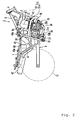
- Figs. 1 to 3 illustrate a first embodiment (hereinafter Embodiment 1) of a motorcycle 1 in accordance with the invention, in which an intake path 70 for cooling in a belt type continuously variable transmission 17 extends on an outer side of an exhaust pipe 41 in a vehicle width direction to the upper side.
- Embodiment 1 a first embodiment of a motorcycle 1 in accordance with the invention, in which an intake path 70 for cooling in a belt type continuously variable transmission 17 extends on an outer side of an exhaust pipe 41 in a vehicle width direction to the upper side.
- the motorcycle 1 in Embodiment 1 is a so-called off-road type motorcycle.
- the motorcycle 1 comprises a body frame 2, a fuel tank 24 supported on the body frame 2 and a seat 3 supported on the body frame 2 and provided behind the fuel tank 24.
- back-and-forth and lateral directions mean directions in view of a rider sitting on the seat 3.
- extending to the upper side means a case of extending upward as a whole in the specification. It is not limited to a case of extending vertically but includes a case of extending obliquely upward.
- a meaning of "rearward” is not limited to a direction to the rear side along a strictly back-and-forth direction but includes a direction to the rear side along a direction inclining perpendicularly or laterally to the back-and-forth direction. That is to say, the "rearward” in the specification includes a so-called obliquely rear side.
- the body frame 2 includes a head pipe 4, a down tube 5 extending downward from the head pipe 4, a main tube 6 extending rearward from the head pipe 4 above the down tube 5.
- a pair of right and left seat pillars 6a is divided downward from a middle part of the main tube 6.
- a seat rail 7 extending rearward is connected to the seat pillar 6a.
- a middle part of the seat rail 7 is connected to a rear end of a backstay 8.
- a front end of the backstay 8 is connected to a lower end of the seat pillar 6a.
- a front fork 11 is inserted into the head pipe 4 as shown in Fig. 1 .
- a pivot shaft 10 is inserted into the body frame 2.
- a rear wheel 13 is supported on a rear end of the rear arm 9.
- a power unit 15 is supported on the body frame 2.
- the power unit 15 comprises an engine 16 and a belt type continuously variable transmission (referred to as a CVT, hereinafter) 17 although a detail thereof is described later (refer to Fig. 6 ).
- CVT continuously variable transmission
- the engine 16 comprises a crank case 20 and a cylinder 21 extending upward (more particularly, obliquely upward to the front side) from the crank case 20.
- the cylinder 21 includes a cylinder body 21a and a cylinder head 22, as shown in Fig. 2 .
- the so-called cylinder head 22 is assumed to be included in the cylinder 21 in the specification.
- the cylinder 21 rises from the crank case 20 and slightly inclines forward with respect to the vertical direction. In other words, the cylinder 21 greatly inclines with respect to the horizontal line.
- the CVT 17 comprises a primary sheave shaft 23a and a secondary sheave shaft 53.
- a line L1 connecting an axial core 23b of the primary sheave shaft 23a and an axial core 53b of the secondary sheave shaft 53 substantially crosses at right angles with a center line L2 of the cylinder 21 in side view.
- the axial core 53b of the secondary sheave shaft 53 is provided at a position higher than the axial core 23b of the primary sheave shaft 23a.
- the intake pipe 40 On the rear side of the cylinder 21, connected is an intake pipe 40.
- the intake pipe 40 is provided with a carburetor 40a.
- a rear end of the intake pipe 40 is connected to an air chamber 43.
- the air chamber 43 is omitted from drawing in Fig. 1 .
- An exhaust pipe 41 is connected on the front side of the cylinder 21.
- the exhaust pipe 41 projects forward from the cylinder 21 to curve or bend toward the rear side and extends above the transmission case 36 or the crank case 20 to the rear side (refer to Fig. 3 , too).
- the exhaust pipe 41 crosses with the later-described intake path 70 above the transmission case 36.
- a rear end of the exhaust pipe 41 is connected to a muffler 42.
- a belt chamber 38 housing the CVT 17 although that is described in detail later (refer to Fig. 6 ).
- the intake path 70 for supplying the belt chamber 38 with air for cooling.
- the intake path 70 extends obliquely upward to the front side from a part of the transmission case 36, the part located in front of a rear end 21e of the cylinder 21, in side view.
- the intake path 70 comprises an intake duct 71 extending obliquely upward to the front side from the transmission case 36 and an air box 96 connected to an upper end of the intake duct 71.
- the air box 96 is not necessarily provided.
- the intake path 70 may be formed only from the intake duct 71.
- the air box 96 and the intake duct 71 may be formed into one body or separate bodies.
- the air box 96 is an air path forming member whose appearance is formed into the shape of a box.
- the air box 96 may be not necessarily a so-called air chamber for temporarily storing air.
- the air box 96 may be one with a meander flow channel formed inside thereof, for example.
- the air box 96 may be an air chamber, of course.
- an air filter 95 is formed inside the air box 96.
- An intake pipe 96a is connected on an upper and rear side of the air box 96.
- An intake opening 96b opening rearward is formed in the intake pipe 96a.
- the air box 96 is provided on the inner side of the cover 14, as shown in Fig. 1 .
- the intake pipe 96a of the air box 96 is also provided on the inner side of the cover 14. In other words, the air box 96 (including the intake pipe 96a) is covered with the cover 14 in side view.
- the intake path 70 extends to the inner side of the cover 14 and a part of the intake pipe 70 is provided on the inner side of the cover 14, as described above.
- the exhaust pipe 41 and the intake duct 71 are provided on the right side of the cylinder 21, as shown in Fig. 3 .
- the intake duct 71 is adjacent to the cylinder 21 in the vehicle width direction. In other words, the intake duct 71 and the cylinder 21 are overlapped in side view (refer to Fig. 1 ) .
- the exhaust pipe 41 extends rearward between the cylinder 21 and the intake duct 71.
- a rear cushion unit 30 is provided at the center part in the vehicle width direction.
- the rear cushion unit 30 is provided between the main tube 6 and the rear arm 9 to connect the main tube 6 and the rear arm 9, as shown in Fig. 2 .
- the motorcycle 1 in accordance with Embodiment 1 includes only one rear cushion unit 30 and has a so-called mono-suspension structure.
- the rear cushion unit 30 is not limited to one directly connected to the rear arm 9 but may be one connected to the rear arm 9 through a link.
- a battery 50 as shown in Fig. 3 .
- the battery 50 is provided under the seat 3 (refer to Fig. 1 ).
- the air chamber 43 is connected to the intake pipe 43a opening rightward.
- a numeral 80 denotes a footstep.
- Fig. 6 shows a cross section of the power unit 15.
- the power unit 15 comprises the engine 16, the CVT 17, a centrifugal clutch 18 and a reduction mechanism 19.
- the engine 16 is a four cycle type engine repeating a cycle formed from an intake process, a compression process, a combustion process and an exhaust process.
- the engine 16 is a four cycle single cylinder engine.
- the engine 16 comprises the crank case 20, the cylinder body 21a connected to the crank case 20 and the cylinder head 22 connected on the upper side of the cylinder body 21a.
- the cylinder body 21a and the cylinder head 22 form the cylinder 21, as described before.
- the crank case 20 includes two divided case blocks, namely, a first case block 20a located on the left side and a second case block 20b located on the right side.
- the first case block 20a and the second case block 20b are faced to each other along the vehicle width direction.
- crank shaft 23 housed is a crank shaft 23.
- the crank shaft 23 extends in the vehicle width direction and is provided horizontally.
- the crank shaft 23 is supported on the first case block 20a through a bearing 24a and on the second case block 20b through the bearing 24b.
- a piston 25 is slidably inserted into the cylinder 21.
- One end of a connecting rod 26 is connected to the piston 25.
- a crank pin 28 is provided between a left crank arm 27a and a right crank arm 27b of the crank shaft 23. The other end of the connecting rod 26 is connected to the crank pin 28.
- An ignition plug 29 is inserted into the cylinder head 22.
- the intake port is connected to the above-mentioned intake pipe 40 (refer to Fig. 1 ).
- the exhaust port is connected to the exhaust pipe 41 (refer to Fig. 1 ).
- a generator case 35 for housing a generator 34 is mounted to the left side of a front half of the first case block 20a.
- a transmission case 36 for housing the CVT 17 is mounted to the right side of the second case block 20b. Further, on the right side of a rear half of the second case block 20b, formed is an opening, which is covered with a clutch cover 37.
- the transmission case 36 is formed independently from the crank case 20.
- the transmission case 36 is formed from an inner case 36a covering the inner side (the left side) of the CVT 17 in the vehicle width direction and an outer case 36b covering the outer side (the right side) of the CVT 17 in the vehicle width direction.
- the inner case 36a is mounted on the right side of the crank case 20.
- the outer case 36b is mounted on the right side of the inner case 36a.
- Inside the inner case 36a and the outer case 36b, formed is the belt chamber 38 housing the CVT 17.
- An intake opening 78 is formed on an upper surface of the outer case 36b.
- the intake opening 78 is connected to the above-mentioned intake duct 71 (refer to Fig. 1 ).
- a right end of the crank shaft 23 passes through the second case block 20b and the inner case 36a to extend to the belt chamber 38.
- a primary sheave 51 of the CVT 17 is fitted in the right end of the crank shaft 23. Accordingly, the primary sheave 51 rotates in accordance with rotation of the crank shaft 23.
- a right part of the crank shaft 23 (strictly, a part on the right side of the bearing 24b) forms the primary sheave shaft 23a.
- crank shaft 23 passes through the first case block 20a to extend to the inner side of the generation case 35.
- the generator 34 is mounted to the left end of the crank shaft 23.
- the secondary sheave shaft 53 in which a secondary sheave 52 is fitted is provided parallel to the crank shaft 23.
- a part on the right side of a center part of the secondary sheave shaft 53 is supported on the clutch cover 37 through a bearing 54a.
- a part on the left side of the secondary sheave shaft 53 is supported on a left end of the second case block 20b through a bearing 54b.
- the secondary sheave 52 is connected to a right end of the secondary sheave shaft 53.
- the CVT 17 comprises a V-belt 55 wound around the primary sheave 51 and the secondary sheave 52 in addition to the primary sheave 51 and the secondary sheave 52.
- the primary sheave 51 comprises a fixed sheave body 51a located on the outer side in the vehicle width direction and a movable sheave body 51b located on the inner side in the vehicle width direction and faced to the fixed sheave body 51a.
- the fixed sheave body 51a is fixed to a right part of the primary sheave shaft 23a and rotates together with the primary sheave shaft 23a.
- the movable sheave body 51b is provided on the left side of the fixed sheave body 51a and mounted to the primary sheave shaft 23a so as to be freely slidable. Accordingly, the movable sheave body 51b rotates together with the primary sheave shaft 23a and is freely slidable in an axial direction of the primary sheave shaft 23a.
- a belt groove 51c Between the fixed sheave body 51a and the movable sheave body 51b, formed is a belt groove 51c.
- a cam surface 56 is formed in a part of the left side of the movable sheave body 51b.
- a cam plate 57 is provided on the left side of the cam surface 56.
- a roller weight 58 is provided between the cam surface 56 of the movable sheave body 51b and the cam plate 57.
- the secondary sheave 52 comprises a fixed sheave body 52a located on the inner side in the vehicle width direction and a movable sheave body 52b located on the outer side in the vehicle width direction and faced to the fixed sheave body 52a.
- the movable sheave body 52b is fixed to a right part of the secondary sheave shaft 53.
- the movable sheave body 52b rotates together with the secondary sheave shaft 53 and is freely slidable in an axial direction of the secondary sheave shaft 53.
- On the right side of the secondary sheave 52 provided is a compression coil spring 59.
- the movable sheave body 52b receives leftward urging force from the compression coil spring 59.
- An axial core part of the fixed sheave body 52a is a cylindrical slide collar spline-fitted in the secondary sheave shaft 53. Between the fixed sheave body 52a and the movable sheave body 52b, formed is a V-shaped belt groove 52c.
- the V-belt 55 is a so-called resin block belt comprising plural resin blocks and a connection body for connecting the resin blocks.
- the intake opening 78 formed on the upper surface of the transmission case 36 is connected to the intake duct 71 (refer to Fig. 1 ), as described above.
- the intake opening 78 is formed in a front half of the transmission case 36 (above the primary sheave 51). Accordingly, the intake duct 71 is connected in front of a rear end of the primary sheave 51.
- the vane 60 is formed so as to extend spirally outward in the diameter direction from the center part of the fixed sheave body 51a in side view.
- a concrete shape of the vane 60 is not limited at all.
- the number of the vane 60 is also not limited at all. It may be possible to provide a vaned wheel or the like, which is formed separately from the fixed sheave body 51a, on the outer side of the fixed sheave body 51a.
- Fig. 7 is a perspective view of the second case block 20b and the inner case 36a.
- a front half 66 of the inner case 36a is formed into the shape of a bowl projecting leftward while a rear half 67 of the inner case 36a is formed into the shape of a bowl projecting rightward.
- a hole 68 into which the primary sheave shaft 23a (refer to Fig. 6 ) of the CVT 17 is inserted.
- a hole 69 into which the secondary sheave shaft 53 (refer to Fig. 6 ) of the CVT 17 is inserted is formed in the rear half 67.
- the clutch cover 37 (refer to Fig. 6 ) existing between the inner case 36a and the second case block 20b.
- Vents 72 are provided in the inner case 36a.
- the vent 72 is formed into a circular shape.
- the vent 72 is three in number and provided on an upper side of a center position of the inner case 36a in the perpendicular direction.
- the shape and number of the vent 72 are not limited at all.
- the second case block 20b includes a peripheral part 74 rising up rightward.
- the peripheral part 74 is in the shape corresponding to a shape of an outline of the transmission case 36.
- a lower part of the peripheral part 74 is formed into the shape of a slit so that a part of the lower part would be notched, to form a so-called comb shape.
- a space 75 sectioned by the second case block 20b and the inner case 36a communicates with the outside of the power unit 15 (refer to Fig. 6 ) through the vents 73.
- the space 75 is formed between the clutch cover 37 and the inner case 36a in a rear half of the second case block 20b since the right side of the rear half of the second case block 20b is covered with the clutch cover 37 (refer to Fig. 6 ).
- reinforcement ribs 76 In the comb-shaped part of the peripheral part 74, provided are reinforcement ribs 76. An oil pan 77 is provided under the vents 73.
- the air in the belt chamber 38 is led to the space 75 through the vents 72 of the inner case 36a to be exhausted toward the oil pan 77 through the vents 73 of the second case block 20b. As a result, the air is exhausted to the outside of the power unit 15.
- Fig. 8 is an enlarged view of a part shown in Fig. 6 .
- the centrifugal clutch 18 is mounted to a left part of the secondary sheave shaft 53.
- the centrifugal clutch 18 is a wet type multi-plate clutch and comprises a substantially cylindrical clutch housing 81 and a clutch boss 82.
- the clutch housing 81 is spline-fitted in the secondary sheave shaft 53 to rotate in a body with the secondary sheave shaft 53.
- a plural number of ring-shaped clutch plates 83 are mounted to the clutch housing 81.
- a cylindrical gear 85 is fitted through a bearing 84 in the periphery of the left part of the secondary sheave shaft 53 so as to be freely rotatable.
- the clutch boss 82 is provided on the inner side in the diameter direction of the clutch plate 83 and on the outer side in the diameter direction of the gear 85 to engage with the gear 85. This causes the gear 85 to rotate together with the clutch boss 82.
- On the outer side in the diameter direction of the clutch boss 82 mounted are a plural number of ring-shaped friction plates 86.
- the friction plates 86 are provided in line at intervals in an axial direction of the secondary sheave shaft 53. Each of the friction plates 86 is provided between the adjacent clutch plates 83 and 83.
- a roller weight 88 is provided between the cam surface 87 and the most right clutch plate 83 faced to the cam surface 87.
- the centrifugal clutch 18 can be automatically switched between an in-clutch state (namely, a state of connection) and an off-clutch state (namely, a state of disconnection) in accordance with a size of centrifugal force operating on the roller weight 88.
- an in-clutch state namely, a state of connection
- an off-clutch state namely, a state of disconnection
- a part lower than the secondary sheave shaft 53 shows the in-clutch state while a part upper than the secondary sheave shaft 53 shows the out-of-clutch state.
- the reduction mechanism 19 is provided between the centrifugal clutch 18 and an output shaft (not shown).
- the reduction mechanism 19 includes a transmission shaft 89 provided parallel to the secondary sheave shaft 53.
- the transmission shaft 89 is supported on the first case block 20a through a bearing 90 so as to be freely rotatable.
- the transmission shaft 89 is also supported on the second case block 20b through a bearing 91 so as to be freely rotatable.
- On a right end of the transmission shaft 89 provided is a first transmission gear 92 engaging with the gear 85.
- a second transmission gear 93 having a diameter smaller than that of the first transmission gear 92.
- the second transmission gear 93 is arranged to engage with an output shaft not shown or a gear, which is not shown and provided to the output shaft.
- Such a structure allows the clutch boss 82 and the output shaft to be connected through the gear 85, the first transmission gear 92, the transmission shaft 89, the second transmission gear 93 and such. Accordingly, the output shaft rotates in accordance with rotation of the clutch boss 82.
- a power transmission mechanism for transmitting driving force of the output shaft to the rear wheel 13 (refer to Fig. 1 ) such as a chain although this is not shown in the drawings.
- the primary sheave shaft 23a of the CVT 17 rotates and the vanes 60 of the fixed sheave body 51a of the primary sheave 51 rotate in accordance with the rotation of the primary sheave shaft 23a. This results in generation of sucking force, which leads air from the intake duct 71 toward the belt chamber 38.
- Air is then sucked into the air box 96 through the intake opening 96b (refer to Fig. 4 ) and passes through the filter 95 to be purified. After the above, the air is sucked into the belt chamber 38 through the intake duct 71. The air sucked into the belt chamber 38 flows in the periphery of the primary sheave 51, the secondary sheave 52 and the V-belt 55 to cool the primary sheave 51, the secondary sheave 52 and the V-belt 55.
- the air having cooled the primary sheave 51, the secondary sheave 52 and the V-belt 55 is exhausted from the belt chamber 38 through the vents 72 of the inner case 36a (refer to Fig. 7 ) to flow into the space 75 between the inner case 36a and the second case block 20b.
- the air in the space 75 is exhausted to the outside of the power unit 15 through the vents 73 formed in the lower part of the second case block 20b.
- Such a flow of air causes the CVT 17 to be continuously and regularly cooled.
- the four cycle type engine 16 is used while the intake path 70 extending upward from a part of the transmission case 36, the part located in front of the rear end 21e of the cylinder 21, in side view (refer to Fig. 1 ) is provided for the purpose of supplying the CVT 17 with air for cooling.
- the exhaust pipe 41 to be narrowed, so that a surplus space can be secured above the crank case 20.
- Effectively using the surplus space as a space for providing the intake path 70 allows the intake path 70 to be provided upward without any obstruction by the cylinder 21 and the exhaust pipe 41. Accordingly, water and dust rose from the ground can be effectively prevented from entering, differently from a case of providing the whole of the intake path 70 at a position lower than the upper end of the crank case 20, so that the intake path 70 can be preferably provided.
- the CVT 17 including the preferable intake path 70 can be mounted in spite of an off-road type vehicle.
- the four cycle type engine 16 is used while the intake path 70 extending upward from the transmission case 36 in side view (refer to Fig. 1 ) is provided for the purpose of supplying the CVT 17 with air for cooling, and furthermore, the exhaust pipe 41 is provided so as to cross with the intake path 70 above the transmission case 36 in side view.
- the intake path 70 extends upward from a part of the transmission case 36, the part in front of the rear end 21e of the cylinder 21, in side view. Such a structure is more preferable.
- the intake path 70 may extend from a part located behind the rear end 21e of the cylinder 21 so long as the exhaust pipe 41 crosses with the intake path 70 above the transmission case 36 in side view.
- the intake path 70 is arranged to be provided adjacently to the cylinder 21 in the vehicle width direction in Embodiment 1. Further, the exhaust pipe 41 is arranged to extend between the cylinder 21 and the intake path 70. These allow the cylinder 21, the exhaust pipe 41 and the intake path 70 to be provided at a higher density, so that the vehicle can be miniaturized.
- a sucking part of the intake path 70 namely, the intake pipe 96a is provided on an inner side of the cover 14. Accordingly, the cover 14 effectively prevents mud or the like from entering the intake path 70. Further, there is a certain degree of space on the inner side of the cover 14. Effectively using the space as a space for providing a part of the intake path 70 (mainly the air box 96, in Embodiment 1) allows the whole vehicle to be made compact.
- the intake opening 96b of the intake pipe 96a is open rearward in accordance with Embodiment 1. This causes mud or the like to be further prevented from entering the intake path 70. Further, rainwater can be effectively prevented from entering the intake path 70 even in the case of rain. Particularly, the intake opening 96b of the intake pipe 96a is faced to the inner surface of the cover 14 in Embodiment 1. Accordingly, mud or the like can be prevented more from entering through the intake opening 96b.
- the air box 96 including the air filter 95 built in is provided on the inner side of the cover 14.
- the air filter 95 is comparatively large component. Putting a comparatively large space on the inner side of the cover 14 to practical use like Embodiment 1, however, allows the air filter 95 to be prevented from projecting to the outside, so that the air filter 95 can be provided compactly.
- Embodiment 2 The motorcycle 1 in accordance with a second embodiment (hereinafter Embodiment 2) is one in which the location of the exhaust pipe 41 in Embodiment 1 is changed, as shown in Figs. 9 and 10 .
- Embodiment 2 a component similar to that of Embodiment 1 is marked with the same reference signs and numerals and a part different from Embodiment 1 is only described.
- the exhaust pipe 41 extends rearward on the left side of the cylinder 21 in Embodiment 2. That is to say, the exhaust pipe 41 extends rearward on a side opposite to a side of the intake path 70 of the cylinder 21.
- the air chamber 43 is provided on the right side of the rear cushion unit 30 and the battery 50, as shown in Fig. 10 .
- the intake pipe 43a of the air chamber 43 opens leftward.
- the intake duct 71 of the intake path 70 is provided on the right side of the cylinder 21, the exhaust pipe 41 is provided on the left side of the cylinder 21 and the intake path 70 and the exhaust pipe 41 are provided on sides opposite to each other. Accordingly, the intake path 70 can extend upward from the transmission case 36 without obstruction by the exhaust pipe 41, so that a preferable intake path 70 can be achieved. Moreover, the exhaust pipe 41 does not project in the vehicle width direction even in the case that the exhaust pipe 41, the cylinder 21 and the intake path 70 are in line in the vehicle width direction since the engine 16 is a four cycle type engine and the exhaust pipe 41 is thin. This allows the intake path 70 for cooling in the CVT 17 to be preferably provided without increasing the size of the vehicle.
- the motorcycle 1 is an off-road vehicle.
- the off-road vehicle in the above context means a motorcycle suitable for running on a bad road.
- the off-road vehicle may be one running on a paved road, of course.
- the motorcycle in accordance with the invention may be a motorcycle of a type equal to an off-road vehicle.
- the motorcycle in accordance with the invention may be a motorcycle unsuitable for running on a bad road in practice although it is an off-road type motorcycle in appearance.
- the whole of the intake path 70 extends upward from a part located in front of the rear end 21e of the cylinder 21.
- the whole of the air box 96 including the sucking part 96a is provided on the inner side of the cover 14 in the embodiments. It may be possible, however, that a part of the air box 96 or a part of the sucking part 96a is only provided on the outer side of the cover 14.
- extending upward in the specification means a case of extending upward as a whole. It is not limited to a case of extending vertically upward but includes a case of extending obliquely upward. Accordingly, a case of extending obliquely upward to the front side or the like corresponds to the case of "extending upward” in the specification.
- opening rearward is not limited to a case of opening rearward along the back-and-forth direction, namely, a case of opening rearward in the strict sense of the word.
- Opening rearward in the specification also includes a case of opening rearward along a direction inclining perpendicularly or laterally to the back-and-forth direction, namely, a case of opening toward the so-called obliquely rear side.
- a cylinder in the specification includes not only a cylindrical member into which a piston is inserted, namely, a cylinder body but also a so-called cylinder head.
- the invention finds application to a motorcycle.
Claims (9)
- Motocyclette (1) comprenant :un moteur à quatre temps (16) incluant un carter (20) et un cylindre (21) s'étendant vers le haut depuis le carter (20) ;une transmission à courroie à variation continue (17) placée à une extrémité du carter (20) dans une direction transversale de la motocyclette ;un carter de boîte de vitesses (36) couvrant au moins une partie de la transmission à courroie à variation continue (17) et à l'intérieur duquel une chambre pour courroie (38) est formée pour loger la transmission à courroie à variation continue (17) ;un chemin d'admission (70) s'étendant vers le haut depuis le carter de boîte de vitesses (36) sur une vue de côté de la motocyclette pour amener de l'air dans la chambre pour courroie (38) ; et caractérisée par :un tuyau d'échappement (41) raccordé au cylindre (21) et croisant le chemin d'admission (70) au-dessus du carter de boîte de vitesses (36) sur une vue de côté de la motocyclette.
- Motocyclette (1) selon la revendication 1, comprenant en outre :un réservoir de carburant (24) ; etune paire de couvercles droit et gauche (14) placés sur les côtés du réservoir de carburant (24) et formés de manière à s'élargir en direction du côté avant dans la direction transversale de la motocyclette sur une vue en plan,dans laquellele chemin d'admission (70) comprend au moins une partie (96) placée sur un côté intérieur des couvercles (14) et comprend une partie d'aspiration (96a) pour aspirer de l'air.
- Motocyclette (1) selon la revendication 2, dans laquelle une ouverture d'admission (96b) s'ouvrant vers l'arrière est formée dans la partie d'aspiration (96a).
- Motocyclette (1) selon la revendication 1, comprenant en outre ;un réservoir de carburant (24) ; etune paire de couvercles droit et gauche (14) placés sur les côtés du réservoir de carburant (24) et formés de manière à s'élargir en direction du côté avant dans la direction transversale de la motocyclette sur une vue en plan,dans laquellele chemin d'admission (70) comprend une gaine d'admission (71) s'étendant vers le haut depuis le carter de boîte de vitesses (36) et un élément en forme de boîtier (96) placée à l'intérieur des couvercles (14), relié à la gained'admission (71) et contenant un filtre à air (95).
- Motocyclette (1) selon l'une quelconque des revendications précédentes, dans laquelle
le chemin d'admission (70) est adjacent au cylindre (21) dans la direction transversale de la motocyclette. - Motocyclette (1) selon la revendication 5, dans laquelle
le tuyau d'échappement (41) s'étend vers l'arrière entre le cylindre (21) et le chemin d'admission (70). - Motocyclette (1) selon la revendication 5, dans laquelle
le tuyau d'échappement (41) s'étend vers l'arrière sur un côté du cylindre (21), le côté se trouvant à l'opposé d'un côté du chemin d'admission (70). - Motocyclette (1) selon l'une quelconque des revendications précédentes, dans laquelle
la transmission à courroie à variation continue (17) comprend une poulie primaire (51), une poulie secondaire (52), une courroie trapézoïdale (55) enroulée autour de la poulie primaire (51) et de la poulie secondaire (52), un arbre de poulie primaire (23a) positionné en un centre de rotation de la poulie primaire (51) et un arbre de poulie secondaire (53) positionné en un centre de rotation de la poulie secondaire (52) et une ligne (L1) reliant un noyau axial (23b) de l'arbre de poulie primaire (23a) et un noyau axial (53b) de l'arbre de poulie secondaire (53) coupe sensiblement à angle droit une ligne centrale (L2) du cylindre (21) sur une vue de côté de la motocyclette. - Motocyclette (1) selon l'une quelconque des revendications précédentes, dans laquelle
le chemin d'admission (70) s'étend vers le haut depuis une partie (78) du carter de boîte de vitesses (36), ladite partie (78) se trouvant devant une extrémité arrière (21e) du cylindre (21) sur une vue de côté de la motocyclette.
Priority Applications (1)
| Application Number | Priority Date | Filing Date | Title |
|---|---|---|---|
| EP09011370A EP2123942B1 (fr) | 2006-11-29 | 2007-11-20 | Motocyle |
Applications Claiming Priority (2)
| Application Number | Priority Date | Filing Date | Title |
|---|---|---|---|
| JP2006322066A JP5348839B2 (ja) | 2006-11-29 | 2006-11-29 | ベルト式無段変速装置およびそれを備えた鞍乗型車両 |
| JP2007016494A JP2008185055A (ja) | 2007-01-26 | 2007-01-26 | 自動二輪車 |
Related Child Applications (2)
| Application Number | Title | Priority Date | Filing Date |
|---|---|---|---|
| EP09011370A Division EP2123942B1 (fr) | 2006-11-29 | 2007-11-20 | Motocyle |
| EP09011370.5 Division-Into | 2009-09-04 |
Publications (3)
| Publication Number | Publication Date |
|---|---|
| EP1927792A2 EP1927792A2 (fr) | 2008-06-04 |
| EP1927792A3 EP1927792A3 (fr) | 2009-01-07 |
| EP1927792B1 true EP1927792B1 (fr) | 2010-02-17 |
Family
ID=39205018
Family Applications (2)
| Application Number | Title | Priority Date | Filing Date |
|---|---|---|---|
| EP09011370A Not-in-force EP2123942B1 (fr) | 2006-11-29 | 2007-11-20 | Motocyle |
| EP07254520A Not-in-force EP1927792B1 (fr) | 2006-11-29 | 2007-11-20 | Motocyle |
Family Applications Before (1)
| Application Number | Title | Priority Date | Filing Date |
|---|---|---|---|
| EP09011370A Not-in-force EP2123942B1 (fr) | 2006-11-29 | 2007-11-20 | Motocyle |
Country Status (6)
| Country | Link |
|---|---|
| US (1) | US8347993B2 (fr) |
| EP (2) | EP2123942B1 (fr) |
| AT (2) | ATE458160T1 (fr) |
| BR (1) | BRPI0704188A (fr) |
| DE (2) | DE602007014112D1 (fr) |
| ES (1) | ES2339495T3 (fr) |
Families Citing this family (26)
| Publication number | Priority date | Publication date | Assignee | Title |
|---|---|---|---|---|
| JP4963976B2 (ja) * | 2007-01-26 | 2012-06-27 | ヤマハ発動機株式会社 | 樹脂ブロックベルトを有するベルト式無段変速機を備えた鞍乗型車両 |
| JP2009047247A (ja) * | 2007-08-20 | 2009-03-05 | Yamaha Motor Co Ltd | エアクリーナ、無段変速機のケース、エンジンユニット及び鞍乗型車両 |
| JP2009161012A (ja) * | 2007-12-28 | 2009-07-23 | Yamaha Motor Co Ltd | 自動二輪車 |
| US8403100B2 (en) * | 2008-08-08 | 2013-03-26 | Yamaha Motor Co., Ltd. | Vehicle and vehicle exhaust pipe |
| JP3154340U (ja) * | 2008-08-08 | 2009-10-15 | ヤマハ発動機株式会社 | 自動二輪車 |
| JP5339603B2 (ja) * | 2009-03-30 | 2013-11-13 | 本田技研工業株式会社 | 自動二輪車 |
| US8584864B2 (en) | 2010-11-19 | 2013-11-19 | Coldcrete, Inc. | Eliminating screens using a perforated wet belt and system and method for cement cooling |
| JP5810017B2 (ja) * | 2012-03-22 | 2015-11-11 | 本田技研工業株式会社 | 鞍乗型車両の燃料供給構造 |
| JP5961492B2 (ja) * | 2012-08-31 | 2016-08-02 | 本田技研工業株式会社 | 鞍乗リ型車両の後部構造 |
| US8845940B2 (en) | 2012-10-25 | 2014-09-30 | Carboncure Technologies Inc. | Carbon dioxide treatment of concrete upstream from product mold |
| US8910472B2 (en) * | 2012-12-27 | 2014-12-16 | Kawasaki Jukogyo Kabushiki Kaisha | Utility vehicle |
| AU2014212083A1 (en) | 2013-02-04 | 2015-08-06 | Coldcrete, Inc. | System and method of applying carbon dioxide during the production of concrete |
| JP2014177222A (ja) * | 2013-03-15 | 2014-09-25 | Yamaha Motor Co Ltd | 鞍乗型車両 |
| US20160107939A1 (en) | 2014-04-09 | 2016-04-21 | Carboncure Technologies Inc. | Methods and compositions for concrete production |
| US10927042B2 (en) | 2013-06-25 | 2021-02-23 | Carboncure Technologies, Inc. | Methods and compositions for concrete production |
| US9376345B2 (en) | 2013-06-25 | 2016-06-28 | Carboncure Technologies Inc. | Methods for delivery of carbon dioxide to a flowable concrete mix |
| US9388072B2 (en) | 2013-06-25 | 2016-07-12 | Carboncure Technologies Inc. | Methods and compositions for concrete production |
| WO2015123769A1 (fr) | 2014-02-18 | 2015-08-27 | Carboncure Technologies, Inc. | Carbonatation de mélanges de ciment |
| EP3129126A4 (fr) | 2014-04-07 | 2018-11-21 | Carboncure Technologies Inc. | Capture de dioxyde de carbone intégrée |
| US10780941B2 (en) | 2014-08-25 | 2020-09-22 | Radial Engine Innovations Holding LLC | Steering assembly for a motorcycle having a continuously variable transmission |
| US10336399B2 (en) | 2014-08-25 | 2019-07-02 | Radial Engine Innovations Holding LLC | Steering assembly for a motorcycle having a continuously variable transmission |
| US9463847B2 (en) | 2014-08-25 | 2016-10-11 | Radial Engine Innovations Holding LLC | Continuously variable transmission on a motorcycle |
| JP6401076B2 (ja) * | 2015-02-23 | 2018-10-03 | 株式会社ショーワ | ハウジング構造および操舵装置 |
| AU2017249444B2 (en) | 2016-04-11 | 2022-08-18 | Carboncure Technologies Inc. | Methods and compositions for treatment of concrete wash water |
| US10407127B2 (en) * | 2016-11-24 | 2019-09-10 | Shimano Inc. | Bicycle sprocket |
| SG11201912759RA (en) | 2017-06-20 | 2020-01-30 | Carboncure Tech Inc | Methods and compositions for treatment of concrete wash water |
Family Cites Families (39)
| Publication number | Priority date | Publication date | Assignee | Title |
|---|---|---|---|---|
| JPS5752629A (en) * | 1980-09-17 | 1982-03-29 | Honda Motor Co Ltd | Turbo-charger unit in motor cycle |
| US4531928A (en) * | 1981-12-23 | 1985-07-30 | Honda Giken Kogyo Kabushiki Kaisha | Belt transmission having air cooling function |
| US4531606A (en) * | 1982-02-06 | 1985-07-30 | Yamaha Hatsudoki Kabushiki Kaisha | Air cleaner for three wheel vehicle |
| JPS599365A (ja) | 1982-07-07 | 1984-01-18 | Honda Motor Co Ltd | 内燃機関の冷却装置 |
| JPH0657547B2 (ja) | 1983-03-09 | 1994-08-03 | 本田技研工業株式会社 | 内燃機関の冷却装置 |
| JPS6140864A (ja) | 1984-08-02 | 1986-02-27 | 東洋電化工業株式会社 | 軽量なる珪酸カルシウム成型体の製造方法 |
| US4671781A (en) * | 1984-08-03 | 1987-06-09 | Honda Giken Kogyo Kabushiki Kaisha | Cooling system for a belt type transmission |
| US4697665A (en) * | 1985-06-18 | 1987-10-06 | Polaris Industries, Inc. | Recreational vehicle with air cooled transmission |
| JPS6255412A (ja) * | 1985-09-04 | 1987-03-11 | Suzuki Motor Co Ltd | ベルト式伝動装置の冷却装置 |
| JPH0399992A (ja) * | 1989-09-12 | 1991-04-25 | Suzuki Motor Corp | 自動2輪車のラジエタ装置 |
| JPH0569872A (ja) * | 1991-09-17 | 1993-03-23 | Honda Motor Co Ltd | 自動二輪車のシユラウド取付構造 |
| JP3307671B2 (ja) * | 1992-05-22 | 2002-07-24 | スズキ株式会社 | スクータ用パワーユニットのベルトケース内部冷却装置 |
| JPH0657547A (ja) | 1992-08-05 | 1994-03-01 | Kanebo Ltd | 紡績糸の製造方法及び装置 |
| JP3834893B2 (ja) * | 1996-11-13 | 2006-10-18 | スズキ株式会社 | 小型自動二輪車 |
| JPH1111171A (ja) * | 1997-04-28 | 1999-01-19 | Yamaha Motor Co Ltd | エンジンの動力伝達装置 |
| JPH10299873A (ja) * | 1997-04-30 | 1998-11-13 | Suzuki Motor Corp | スクーター型車両のvベルト自動変速機冷却装置 |
| JPH1111170A (ja) * | 1997-06-26 | 1999-01-19 | Yamaha Motor Co Ltd | 不整地走行用車両のベルト室冷却構造 |
| JP4141529B2 (ja) * | 1998-04-23 | 2008-08-27 | ヤマハ発動機株式会社 | スクータ型車両 |
| JP3709973B2 (ja) * | 2000-03-31 | 2005-10-26 | 本田技研工業株式会社 | ベルト式変速装置 |
| JP2002225772A (ja) * | 2001-02-02 | 2002-08-14 | Kawasaki Heavy Ind Ltd | 騎乗型四輪不整地走行車 |
| JP4010127B2 (ja) * | 2001-09-14 | 2007-11-21 | スズキ株式会社 | 変速機構の冷却構造 |
| TW561262B (en) * | 2001-10-19 | 2003-11-11 | Yamaha Motor Co Ltd | Tipping detecting device for a motorcycle |
| US6651769B2 (en) * | 2002-01-03 | 2003-11-25 | Next World Design, Inc. | Fender assembly and system for racing motorcycle vehicles |
| CN101220770A (zh) * | 2002-04-08 | 2008-07-16 | 雅马哈发动机株式会社 | 发动机 |
| JP2004156657A (ja) * | 2002-11-05 | 2004-06-03 | Yamaha Motor Co Ltd | エンジンの駆動ベルト冷却構造 |
| JP4359040B2 (ja) * | 2002-12-26 | 2009-11-04 | ヤマハ発動機株式会社 | Vベルト式無段変速機の冷却構造 |
| JP4384457B2 (ja) * | 2003-09-09 | 2009-12-16 | 本田技研工業株式会社 | エンジン |
| CA2505674C (fr) * | 2004-02-10 | 2008-12-16 | Bush Hog, L.L.C. | Mecanisme de train de transmission avec circulation d'air directe pour vehicule utilitaire |
| JP4476720B2 (ja) * | 2004-07-02 | 2010-06-09 | 本田技研工業株式会社 | 自動2輪車用フェンダー構造 |
| JP4586438B2 (ja) * | 2004-07-08 | 2010-11-24 | スズキ株式会社 | 不整地走行車両の前部構造 |
| EP1619419B1 (fr) * | 2004-07-19 | 2012-07-25 | Kwang Yang Motor Co., Ltd. | Couverture de boîte de vitesses pour véhicule tout terrain |
| JP2006274855A (ja) * | 2005-03-28 | 2006-10-12 | Honda Motor Co Ltd | 車両用パワーユニットの変速機構造 |
| JP4684715B2 (ja) * | 2005-04-01 | 2011-05-18 | 川崎重工業株式会社 | 車輌のシュラウド |
| JP2006290295A (ja) * | 2005-04-14 | 2006-10-26 | Yamaha Motor Co Ltd | 鞍乗型車両 |
| JP2007038736A (ja) * | 2005-08-01 | 2007-02-15 | Yamaha Motor Co Ltd | 鞍乗型車両 |
| JP2007062716A (ja) * | 2005-08-01 | 2007-03-15 | Yamaha Motor Co Ltd | 鞍乗型車両 |
| JP4963976B2 (ja) * | 2007-01-26 | 2012-06-27 | ヤマハ発動機株式会社 | 樹脂ブロックベルトを有するベルト式無段変速機を備えた鞍乗型車両 |
| JP2009083810A (ja) * | 2007-10-03 | 2009-04-23 | Yamaha Motor Co Ltd | 自動二輪車 |
| JP2009202827A (ja) * | 2008-02-29 | 2009-09-10 | Yamaha Motor Co Ltd | 自動二輪車 |
-
2007
- 2007-11-20 AT AT07254520T patent/ATE458160T1/de not_active IP Right Cessation
- 2007-11-20 AT AT09011370T patent/ATE506557T1/de not_active IP Right Cessation
- 2007-11-20 EP EP09011370A patent/EP2123942B1/fr not_active Not-in-force
- 2007-11-20 DE DE602007014112T patent/DE602007014112D1/de active Active
- 2007-11-20 DE DE602007004795T patent/DE602007004795D1/de active Active
- 2007-11-20 EP EP07254520A patent/EP1927792B1/fr not_active Not-in-force
- 2007-11-20 ES ES07254520T patent/ES2339495T3/es active Active
- 2007-11-27 BR BRPI0704188-8A patent/BRPI0704188A/pt not_active Application Discontinuation
- 2007-11-28 US US11/946,719 patent/US8347993B2/en not_active Expired - Fee Related
Also Published As
| Publication number | Publication date |
|---|---|
| EP1927792A2 (fr) | 2008-06-04 |
| DE602007004795D1 (de) | 2010-04-01 |
| DE602007014112D1 (de) | 2011-06-01 |
| BRPI0704188A (pt) | 2008-07-15 |
| EP2123942B1 (fr) | 2011-04-20 |
| EP1927792A3 (fr) | 2009-01-07 |
| ATE506557T1 (de) | 2011-05-15 |
| ES2339495T3 (es) | 2010-05-20 |
| US8347993B2 (en) | 2013-01-08 |
| ATE458160T1 (de) | 2010-03-15 |
| US20080121455A1 (en) | 2008-05-29 |
| EP2123942A1 (fr) | 2009-11-25 |
Similar Documents
| Publication | Publication Date | Title |
|---|---|---|
| EP1927792B1 (fr) | Motocyle | |
| US8157038B2 (en) | Saddle-ride type vehicle | |
| ES2364897T3 (es) | Motocicleta. | |
| US8596406B2 (en) | Utility vehicle | |
| US7647995B2 (en) | Riding type vehicle | |
| US7487853B2 (en) | Saddle-type vehicle | |
| JP6476301B2 (ja) | 鞍乗型車両のパワーユニット | |
| JP4259976B2 (ja) | 自動二輪車及び自動二輪車用エンジン | |
| KR101063066B1 (ko) | 벨트식 무단 변속기의 냉각 구조 | |
| EP2620611B1 (fr) | Moteur à combustion interne et véhicule de type à califourchon comprenant celui-ci | |
| JP4316331B2 (ja) | 自動二輪車用v型エンジンの吸気装置 | |
| JP3150482U (ja) | 鞍乗型車両 | |
| JP4530928B2 (ja) | 小型車両のラジエータ装置 | |
| ITTO20011005A1 (it) | Gruppo radiatore per veicolo. | |
| CN1205409C (zh) | 火花点火四冲程发动机 | |
| JP4776561B2 (ja) | 強制空冷式内燃機関 | |
| JP3150483U (ja) | 自動二輪車 | |
| CN1213221C (zh) | 发动机的吸气装置 | |
| JP2008185055A (ja) | 自動二輪車 | |
| JP4999582B2 (ja) | 自動二輪車用パワーユニットの変速機ケース冷却構造 | |
| JP4719707B2 (ja) | 車両用パワーユニットの冷却構造 | |
| CN116324224A (zh) | 用于鞍式车辆的动力传动装置布局 | |
| EP1580113B1 (fr) | Dispositif d'entraînement et véhicule | |
| TR201720826A2 (tr) | İçten yanmali bi̇r motor i̇çi̇n bi̇r soğutma si̇stemi̇ | |
| JP2018167685A (ja) | 鞍乗り型車両 |
Legal Events
| Date | Code | Title | Description |
|---|---|---|---|
| PUAI | Public reference made under article 153(3) epc to a published international application that has entered the european phase |
Free format text: ORIGINAL CODE: 0009012 |
|
| AK | Designated contracting states |
Kind code of ref document: A2 Designated state(s): AT BE BG CH CY CZ DE DK EE ES FI FR GB GR HU IE IS IT LI LT LU LV MC MT NL PL PT RO SE SI SK TR |
|
| AX | Request for extension of the european patent |
Extension state: AL BA HR MK RS |
|
| PUAL | Search report despatched |
Free format text: ORIGINAL CODE: 0009013 |
|
| AK | Designated contracting states |
Kind code of ref document: A3 Designated state(s): AT BE BG CH CY CZ DE DK EE ES FI FR GB GR HU IE IS IT LI LT LU LV MC MT NL PL PT RO SE SI SK TR |
|
| AX | Request for extension of the european patent |
Extension state: AL BA HR MK RS |
|
| 17P | Request for examination filed |
Effective date: 20090702 |
|
| AKX | Designation fees paid |
Designated state(s): AT BE BG CH CY CZ DE DK EE ES FI FR GB GR HU IE IS IT LI LT LU LV MC MT NL PL PT RO SE SI SK TR |
|
| GRAP | Despatch of communication of intention to grant a patent |
Free format text: ORIGINAL CODE: EPIDOSNIGR1 |
|
| GRAS | Grant fee paid |
Free format text: ORIGINAL CODE: EPIDOSNIGR3 |
|
| GRAA | (expected) grant |
Free format text: ORIGINAL CODE: 0009210 |
|
| AK | Designated contracting states |
Kind code of ref document: B1 Designated state(s): AT BE BG CH CY CZ DE DK EE ES FI FR GB GR HU IE IS IT LI LT LU LV MC MT NL PL PT RO SE SI SK TR |
|
| REG | Reference to a national code |
Ref country code: GB Ref legal event code: FG4D |
|
| REG | Reference to a national code |
Ref country code: CH Ref legal event code: EP |
|
| REG | Reference to a national code |
Ref country code: IE Ref legal event code: FG4D |
|
| REF | Corresponds to: |
Ref document number: 602007004795 Country of ref document: DE Date of ref document: 20100401 Kind code of ref document: P |
|
| REG | Reference to a national code |
Ref country code: GR Ref legal event code: EP Ref document number: 20100400897 Country of ref document: GR |
|
| REG | Reference to a national code |
Ref country code: ES Ref legal event code: FG2A Ref document number: 2339495 Country of ref document: ES Kind code of ref document: T3 |
|
| REG | Reference to a national code |
Ref country code: NL Ref legal event code: VDEP Effective date: 20100217 |
|
| LTIE | Lt: invalidation of european patent or patent extension |
Effective date: 20100217 |
|
| PG25 | Lapsed in a contracting state [announced via postgrant information from national office to epo] |
Ref country code: IS Free format text: LAPSE BECAUSE OF FAILURE TO SUBMIT A TRANSLATION OF THE DESCRIPTION OR TO PAY THE FEE WITHIN THE PRESCRIBED TIME-LIMIT Effective date: 20100617 Ref country code: LT Free format text: LAPSE BECAUSE OF FAILURE TO SUBMIT A TRANSLATION OF THE DESCRIPTION OR TO PAY THE FEE WITHIN THE PRESCRIBED TIME-LIMIT Effective date: 20100217 Ref country code: PT Free format text: LAPSE BECAUSE OF FAILURE TO SUBMIT A TRANSLATION OF THE DESCRIPTION OR TO PAY THE FEE WITHIN THE PRESCRIBED TIME-LIMIT Effective date: 20100617 |
|
| PG25 | Lapsed in a contracting state [announced via postgrant information from national office to epo] |
Ref country code: FI Free format text: LAPSE BECAUSE OF FAILURE TO SUBMIT A TRANSLATION OF THE DESCRIPTION OR TO PAY THE FEE WITHIN THE PRESCRIBED TIME-LIMIT Effective date: 20100217 Ref country code: SI Free format text: LAPSE BECAUSE OF FAILURE TO SUBMIT A TRANSLATION OF THE DESCRIPTION OR TO PAY THE FEE WITHIN THE PRESCRIBED TIME-LIMIT Effective date: 20100217 Ref country code: PL Free format text: LAPSE BECAUSE OF FAILURE TO SUBMIT A TRANSLATION OF THE DESCRIPTION OR TO PAY THE FEE WITHIN THE PRESCRIBED TIME-LIMIT Effective date: 20100217 Ref country code: LV Free format text: LAPSE BECAUSE OF FAILURE TO SUBMIT A TRANSLATION OF THE DESCRIPTION OR TO PAY THE FEE WITHIN THE PRESCRIBED TIME-LIMIT Effective date: 20100217 Ref country code: AT Free format text: LAPSE BECAUSE OF FAILURE TO SUBMIT A TRANSLATION OF THE DESCRIPTION OR TO PAY THE FEE WITHIN THE PRESCRIBED TIME-LIMIT Effective date: 20100217 |
|
| PG25 | Lapsed in a contracting state [announced via postgrant information from national office to epo] |
Ref country code: CY Free format text: LAPSE BECAUSE OF FAILURE TO SUBMIT A TRANSLATION OF THE DESCRIPTION OR TO PAY THE FEE WITHIN THE PRESCRIBED TIME-LIMIT Effective date: 20100217 Ref country code: BE Free format text: LAPSE BECAUSE OF FAILURE TO SUBMIT A TRANSLATION OF THE DESCRIPTION OR TO PAY THE FEE WITHIN THE PRESCRIBED TIME-LIMIT Effective date: 20100217 Ref country code: SE Free format text: LAPSE BECAUSE OF FAILURE TO SUBMIT A TRANSLATION OF THE DESCRIPTION OR TO PAY THE FEE WITHIN THE PRESCRIBED TIME-LIMIT Effective date: 20100217 Ref country code: NL Free format text: LAPSE BECAUSE OF FAILURE TO SUBMIT A TRANSLATION OF THE DESCRIPTION OR TO PAY THE FEE WITHIN THE PRESCRIBED TIME-LIMIT Effective date: 20100217 Ref country code: EE Free format text: LAPSE BECAUSE OF FAILURE TO SUBMIT A TRANSLATION OF THE DESCRIPTION OR TO PAY THE FEE WITHIN THE PRESCRIBED TIME-LIMIT Effective date: 20100217 Ref country code: RO Free format text: LAPSE BECAUSE OF FAILURE TO SUBMIT A TRANSLATION OF THE DESCRIPTION OR TO PAY THE FEE WITHIN THE PRESCRIBED TIME-LIMIT Effective date: 20100217 |
|
| PG25 | Lapsed in a contracting state [announced via postgrant information from national office to epo] |
Ref country code: CZ Free format text: LAPSE BECAUSE OF FAILURE TO SUBMIT A TRANSLATION OF THE DESCRIPTION OR TO PAY THE FEE WITHIN THE PRESCRIBED TIME-LIMIT Effective date: 20100217 Ref country code: BG Free format text: LAPSE BECAUSE OF FAILURE TO SUBMIT A TRANSLATION OF THE DESCRIPTION OR TO PAY THE FEE WITHIN THE PRESCRIBED TIME-LIMIT Effective date: 20100517 Ref country code: SK Free format text: LAPSE BECAUSE OF FAILURE TO SUBMIT A TRANSLATION OF THE DESCRIPTION OR TO PAY THE FEE WITHIN THE PRESCRIBED TIME-LIMIT Effective date: 20100217 |
|
| PLBE | No opposition filed within time limit |
Free format text: ORIGINAL CODE: 0009261 |
|
| STAA | Information on the status of an ep patent application or granted ep patent |
Free format text: STATUS: NO OPPOSITION FILED WITHIN TIME LIMIT |
|
| 26N | No opposition filed |
Effective date: 20101118 |
|
| PG25 | Lapsed in a contracting state [announced via postgrant information from national office to epo] |
Ref country code: DK Free format text: LAPSE BECAUSE OF FAILURE TO SUBMIT A TRANSLATION OF THE DESCRIPTION OR TO PAY THE FEE WITHIN THE PRESCRIBED TIME-LIMIT Effective date: 20100217 |
|
| PG25 | Lapsed in a contracting state [announced via postgrant information from national office to epo] |
Ref country code: MC Free format text: LAPSE BECAUSE OF NON-PAYMENT OF DUE FEES Effective date: 20101130 |
|
| PG25 | Lapsed in a contracting state [announced via postgrant information from national office to epo] |
Ref country code: IE Free format text: LAPSE BECAUSE OF NON-PAYMENT OF DUE FEES Effective date: 20101120 |
|
| PG25 | Lapsed in a contracting state [announced via postgrant information from national office to epo] |
Ref country code: MT Free format text: LAPSE BECAUSE OF FAILURE TO SUBMIT A TRANSLATION OF THE DESCRIPTION OR TO PAY THE FEE WITHIN THE PRESCRIBED TIME-LIMIT Effective date: 20100217 Ref country code: IT Free format text: LAPSE BECAUSE OF NON-PAYMENT OF DUE FEES Effective date: 20101120 |
|
| REG | Reference to a national code |
Ref country code: CH Ref legal event code: PL |
|
| PG25 | Lapsed in a contracting state [announced via postgrant information from national office to epo] |
Ref country code: CH Free format text: LAPSE BECAUSE OF NON-PAYMENT OF DUE FEES Effective date: 20111130 Ref country code: LI Free format text: LAPSE BECAUSE OF NON-PAYMENT OF DUE FEES Effective date: 20111130 |
|
| PG25 | Lapsed in a contracting state [announced via postgrant information from national office to epo] |
Ref country code: LU Free format text: LAPSE BECAUSE OF NON-PAYMENT OF DUE FEES Effective date: 20101120 Ref country code: HU Free format text: LAPSE BECAUSE OF FAILURE TO SUBMIT A TRANSLATION OF THE DESCRIPTION OR TO PAY THE FEE WITHIN THE PRESCRIBED TIME-LIMIT Effective date: 20100818 |
|
| REG | Reference to a national code |
Ref country code: FR Ref legal event code: PLFP Year of fee payment: 9 |
|
| REG | Reference to a national code |
Ref country code: FR Ref legal event code: PLFP Year of fee payment: 10 |
|
| REG | Reference to a national code |
Ref country code: FR Ref legal event code: PLFP Year of fee payment: 11 |
|
| PGFP | Annual fee paid to national office [announced via postgrant information from national office to epo] |
Ref country code: GR Payment date: 20181113 Year of fee payment: 12 Ref country code: DE Payment date: 20181120 Year of fee payment: 12 |
|
| PGFP | Annual fee paid to national office [announced via postgrant information from national office to epo] |
Ref country code: ES Payment date: 20181218 Year of fee payment: 12 Ref country code: GB Payment date: 20181120 Year of fee payment: 12 Ref country code: TR Payment date: 20181023 Year of fee payment: 12 Ref country code: FR Payment date: 20181123 Year of fee payment: 12 Ref country code: IT Payment date: 20181126 Year of fee payment: 12 |
|
| REG | Reference to a national code |
Ref country code: DE Ref legal event code: R119 Ref document number: 602007004795 Country of ref document: DE |
|
| PG25 | Lapsed in a contracting state [announced via postgrant information from national office to epo] |
Ref country code: GR Free format text: LAPSE BECAUSE OF NON-PAYMENT OF DUE FEES Effective date: 20200609 |
|
| GBPC | Gb: european patent ceased through non-payment of renewal fee |
Effective date: 20191120 |
|
| PG25 | Lapsed in a contracting state [announced via postgrant information from national office to epo] |
Ref country code: GB Free format text: LAPSE BECAUSE OF NON-PAYMENT OF DUE FEES Effective date: 20191120 Ref country code: IT Free format text: LAPSE BECAUSE OF NON-PAYMENT OF DUE FEES Effective date: 20191120 Ref country code: FR Free format text: LAPSE BECAUSE OF NON-PAYMENT OF DUE FEES Effective date: 20191130 Ref country code: DE Free format text: LAPSE BECAUSE OF NON-PAYMENT OF DUE FEES Effective date: 20200603 |
|
| REG | Reference to a national code |
Ref country code: ES Ref legal event code: FD2A Effective date: 20210531 |
|
| PG25 | Lapsed in a contracting state [announced via postgrant information from national office to epo] |
Ref country code: ES Free format text: LAPSE BECAUSE OF NON-PAYMENT OF DUE FEES Effective date: 20191121 |
|
| PG25 | Lapsed in a contracting state [announced via postgrant information from national office to epo] |
Ref country code: TR Free format text: LAPSE BECAUSE OF NON-PAYMENT OF DUE FEES Effective date: 20191120 |