EP2025847A2 - Entraînement linéaire pour portes coulissantes ou analogues - Google Patents
Entraînement linéaire pour portes coulissantes ou analogues Download PDFInfo
- Publication number
- EP2025847A2 EP2025847A2 EP08013235A EP08013235A EP2025847A2 EP 2025847 A2 EP2025847 A2 EP 2025847A2 EP 08013235 A EP08013235 A EP 08013235A EP 08013235 A EP08013235 A EP 08013235A EP 2025847 A2 EP2025847 A2 EP 2025847A2
- Authority
- EP
- European Patent Office
- Prior art keywords
- profile
- linear drive
- receiving
- drive according
- suspension
- Prior art date
- Legal status (The legal status is an assumption and is not a legal conclusion. Google has not performed a legal analysis and makes no representation as to the accuracy of the status listed.)
- Withdrawn
Links
Images


Classifications
-
- E—FIXED CONSTRUCTIONS
- E05—LOCKS; KEYS; WINDOW OR DOOR FITTINGS; SAFES
- E05D—HINGES OR SUSPENSION DEVICES FOR DOORS, WINDOWS OR WINGS
- E05D15/00—Suspension arrangements for wings
- E05D15/06—Suspension arrangements for wings for wings sliding horizontally more or less in their own plane
- E05D15/0621—Details, e.g. suspension or supporting guides
- E05D15/0626—Details, e.g. suspension or supporting guides for wings suspended at the top
- E05D15/0652—Tracks
-
- E—FIXED CONSTRUCTIONS
- E05—LOCKS; KEYS; WINDOW OR DOOR FITTINGS; SAFES
- E05F—DEVICES FOR MOVING WINGS INTO OPEN OR CLOSED POSITION; CHECKS FOR WINGS; WING FITTINGS NOT OTHERWISE PROVIDED FOR, CONCERNED WITH THE FUNCTIONING OF THE WING
- E05F15/00—Power-operated mechanisms for wings
- E05F15/60—Power-operated mechanisms for wings using electrical actuators
-
- E—FIXED CONSTRUCTIONS
- E05—LOCKS; KEYS; WINDOW OR DOOR FITTINGS; SAFES
- E05Y—INDEXING SCHEME RELATING TO HINGES OR OTHER SUSPENSION DEVICES FOR DOORS, WINDOWS OR WINGS AND DEVICES FOR MOVING WINGS INTO OPEN OR CLOSED POSITION, CHECKS FOR WINGS AND WING FITTINGS NOT OTHERWISE PROVIDED FOR, CONCERNED WITH THE FUNCTIONING OF THE WING
- E05Y2600/00—Mounting or coupling arrangements for elements provided for in this subclass
- E05Y2600/60—Mounting or coupling members; Accessories therefore
- E05Y2600/626—Plates or brackets
-
- E—FIXED CONSTRUCTIONS
- E05—LOCKS; KEYS; WINDOW OR DOOR FITTINGS; SAFES
- E05Y—INDEXING SCHEME RELATING TO HINGES OR OTHER SUSPENSION DEVICES FOR DOORS, WINDOWS OR WINGS AND DEVICES FOR MOVING WINGS INTO OPEN OR CLOSED POSITION, CHECKS FOR WINGS AND WING FITTINGS NOT OTHERWISE PROVIDED FOR, CONCERNED WITH THE FUNCTIONING OF THE WING
- E05Y2600/00—Mounting or coupling arrangements for elements provided for in this subclass
- E05Y2600/60—Mounting or coupling members; Accessories therefore
- E05Y2600/628—Profiles
-
- E—FIXED CONSTRUCTIONS
- E05—LOCKS; KEYS; WINDOW OR DOOR FITTINGS; SAFES
- E05Y—INDEXING SCHEME RELATING TO HINGES OR OTHER SUSPENSION DEVICES FOR DOORS, WINDOWS OR WINGS AND DEVICES FOR MOVING WINGS INTO OPEN OR CLOSED POSITION, CHECKS FOR WINGS AND WING FITTINGS NOT OTHERWISE PROVIDED FOR, CONCERNED WITH THE FUNCTIONING OF THE WING
- E05Y2800/00—Details, accessories and auxiliary operations not otherwise provided for
- E05Y2800/26—Form, shape
- E05Y2800/27—Form, shape profiles
- E05Y2800/272—Form, shape profiles hollow
-
- E—FIXED CONSTRUCTIONS
- E05—LOCKS; KEYS; WINDOW OR DOOR FITTINGS; SAFES
- E05Y—INDEXING SCHEME RELATING TO HINGES OR OTHER SUSPENSION DEVICES FOR DOORS, WINDOWS OR WINGS AND DEVICES FOR MOVING WINGS INTO OPEN OR CLOSED POSITION, CHECKS FOR WINGS AND WING FITTINGS NOT OTHERWISE PROVIDED FOR, CONCERNED WITH THE FUNCTIONING OF THE WING
- E05Y2900/00—Application of doors, windows, wings or fittings thereof
- E05Y2900/10—Application of doors, windows, wings or fittings thereof for buildings or parts thereof
- E05Y2900/13—Application of doors, windows, wings or fittings thereof for buildings or parts thereof characterised by the type of wing
- E05Y2900/132—Doors
Definitions
- the invention relates to a linear drive for sliding doors or the like, in particular linear motors based on linear motors.
- Linear motor drives for sliding door systems and the like are known.
- the drive consists essentially of a linear motor, which is arranged to extend along at least part of a travel path of a respective sliding door leaf.
- a support profile usually accommodates at least one stator of at least one linear motor.
- Associated runners are mounted on a respective sliding door panel and may be provided with rollers arranged to roll on guide rails.
- the object of the invention is to develop linear actuators such that they are improved in terms of their assembly.
- An inventive linear drive for at least one movable part along a travel, in particular a sliding door has at least one linear motor for the at least one part.
- a stator of the linear motor is taken out safe fall in a recording profile.
- the receiving profile is adapted to be attached to a fastening device, which in turn on-site on a wall or Ceiling section is attached.
- the stator part and the receiving profile form a module or a unit which can be mounted as a whole. An installer can therefore use the receiving profile for mounting, which helps reduce the risk of damaging the stator.
- the receiving profile preferably has a slide-on section at least on an outer side of a side wall. This allows a screwless attachment of the receiving part to other parts or vice versa.
- the Aufschiebeabêt seen in the longitudinal direction of the receiving profile, a dovetail-like cross-sectional shape. Such a design of the Aufschiebeabitess represents a particularly elegant solution to said attachments.
- an additional profile is attached to one of the fastening device side facing away from the receiving profile, which is adapted to receive additional devices of the linear drive, such as a locking module, an escape route module, an energy storage and / or a sensor module.
- additional devices such as a locking module, an escape route module, an energy storage and / or a sensor module.
- the additional devices are not used as usual in the receiving profile for the stator of the linear drive but spatially separated from these housed. This makes it possible to integrate additional equipment even later in the linear drive without having to remove the linear drive necessarily.
- the receiving profile at least on an outer side of the additional profile side facing a Friedebrough on.
- the additional profile in turn has in this case on a side facing the receiving profile on a complementary to the Aufschiebeabêt Aufschiebeabterrorism.
- Receiving profile and additional profile are thus attached to each other by means of facing each other formed Aufschiebeabête.
- the fastening device preferably further comprises a suspension profile, in which in turn the receiving profile is taken out safe fall.
- a suspension profile in which in turn the receiving profile is taken out safe fall.
- the suspension profile is designed so that the receiving profile is fixedly attached to the suspension profile. Ie. the suspension part does not take up the receiving profile.
- the fastening device preferably further comprises a fastening part.
- This attachment part serves to fix the suspension profile and is provided to be arranged on a side facing away from the linear drive of a building-side wall or a fixed part and attached to the suspension profile.
- the suspension profile is in this case arranged on a side of the on-site wall or of the fixed part facing away from the linear drive with the suspension profile.
- This makes it possible to attach the linear drive, for example, to two glass panes which have a certain distance from one another in the area of the linear drive. This thus allows a wall-independent, so to speak "floating" mounting of the linear drive.
- the assembly is carried out in that the suspension profile and the fastening part are screwed together, which allows a particularly simple and in particular detachable mounting.
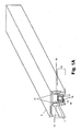
- FIG 1 A a linear drive according to a first embodiment of the invention is shown.
- the linear drive comprises a suspension profile 4, which, viewed in the longitudinal direction, has two receiving spaces next to each other for receiving profiles 10 of a respective linear motor. in the right receiving space is shown a linear motor arrangement.
- a stator part 1 of the linear motor shown here is accommodated in a receiving profile 10, which in turn is accommodated in the suspension profile 4.
- the receiving profile 10 preferably has projections 13, 13 which divide an interior of the receiving profile 10 into an upper receiving space provided for receiving a stator part 1 and a lower receiving space provided for receiving a rotor part 2 of the linear motor.
- On rotor part 2 are preferably rotor rollers 3, 3 freely rotatably arranged such that these in on Figure 1A roll downwards facing surfaces of the projections 13, 13.
- the suspension profile 4 is designed for a telescopic sliding door. Ie. In the left receiving space is also a linear motor recorded, with respect to the in Figure 1A right linear motor is arranged offset.
- FIG. 1 A has the suspension profile 4 at a respective receiving profile facing, preferably side walls each have a Materialsschiebeabites 12.
- the Materialsschiebeabitese 12 are advantageously formed in cross-section complementary to formed on a respective receiving profile 10, oppositely arranged Materialsschiebeabitesen 11.
- outer dimensions or an outer contour of a respective receiving profile 10 are designed so that it comes with inner surfaces of the Aufhangeprofils 4 in clamping engagement, which simplifies a fixation of a position of the receiving profile 10 in the suspension profile 4.
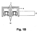
- FIG. 1B shows linear drive according to a second embodiment of the invention, the above-described Aufschiebeabitese 11, 12 be omitted.
- FIG. 1B shows the case of two juxtaposed linear motors.
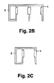
- FIG. 2A is a perspective view of a linear drive according to a third embodiment of the invention shown.
- the additional profile 5 is preferably provided for receiving additional facilities.
- Such devices are, for example, a control or drive circuit for the linear drive, a lock, an escape route module, an electrical energy storage or general sensor technology.
- the electrical memory is provided, for example, for emergencies and is preferably formed by means of a rechargeable battery or by means of high-power capacitors.
- an active infrared sensor system can be used in the additional module 5, which can monitor by means of infrared receivers, in front of each of which an optics is arranged, sharply demarcated monitoring areas in front of the sliding door system or similar installations.
- a passive infrared system may be provided, which responds to general temperature differences.
- the additional profile 5 is designed as a panel or panel. This offers the possibility of visually completing the linear drive.
- the additional profile 5 offers advantages in retrofitting the linear drive. Retrofitted modules or equipment can be mounted without necessarily having to remove the linear drive. On the other hand, the linear drive is suitable for future retrofitting in operation.
- Suspension profile 4 and additional profile 5 can be combined.
- the additional profile 5 can, as in FIG. 2B shown on a left side of the suspension profile 4 of Figure 1 A be additionally designed so that space is created for additional facilities in addition to the receiving spaces of the suspension profile 4.
- FIG. 3A a linear drive according to a fourth embodiment of the invention is shown.
- the suspension profile 4 has no receiving space but is merely provided for attaching the linear drive.
- additional profile 5 and suspension profile 4 can be designed so that they up the linear drive in FIG. 3A cover up.
- the linear drive is in this embodiment on a fixed, relatively thin-walled part, here exemplified as a glass sheet 9, fixed in place.
- a fastening part 6 is furthermore provided which is arranged on a side of the glass pane 9 facing away from the linear drive.
- the glass sheet 9 preferably has passage openings at predetermined locations. Through these passage openings through suspension profile 4 and fastening part 6 are attached or attached to each other. Preferably, this is done by means of fastening screws 7, which are advantageously through a respective passage opening in the suspension profile 4 passing through a respective passage opening in the glass pane 9 guided into the fastening part 6 are screwed. Carrying out the fastening screws 7 in the direction of the fastening part 6 has the advantage that heads of the fastening screws 7 are covered by the female profile 10. Overall, therefore, a simple assembly is possible, in which the fastening means, so the fastening screws 7, are not visible.
- the fastening part preferably has sleeve sections 8 at corresponding points.
- the sleeve sections 8 have female thread sections for screwing in the fastening screws 7 and are formed in the direction of suspension profile 4 protruding.
- a protruding dimension of a respective sleeve portion 8 is smaller than or equal to a depth of a corresponding through hole of the glass sheet 9.
- the respective sleeve portion 8 the respective fastening screw 7 in the region of the passage opening of the glass sheet 9 completely cover, which allows in this area, an optical hiding the mounting screws 7.
- FIG. 3B a linear drive according to a fifth embodiment of the invention is shown.
- the receiving profile 10 is screwed by means of fastening screws 7 on the suspension profile 4 with the fastening part 6.
- the additional profile 5 is attached in the embodiment shown, for example by means of gluing to the receiving profile 10. Alternatively, there is also a screw fastening.
- additional profile 5 and receiving profile 10 are integrally formed.
Applications Claiming Priority (1)
| Application Number | Priority Date | Filing Date | Title |
|---|---|---|---|
| DE102007038840A DE102007038840A1 (de) | 2007-08-16 | 2007-08-16 | Linearantrieb für Schiebetüren oder dergleichen |
Publications (2)
| Publication Number | Publication Date |
|---|---|
| EP2025847A2 true EP2025847A2 (fr) | 2009-02-18 |
| EP2025847A3 EP2025847A3 (fr) | 2013-05-01 |
Family
ID=39870036
Family Applications (1)
| Application Number | Title | Priority Date | Filing Date |
|---|---|---|---|
| EP08013235.0A Withdrawn EP2025847A3 (fr) | 2007-08-16 | 2008-07-23 | Entraînement linéaire pour portes coulissantes ou analogues |
Country Status (3)
| Country | Link |
|---|---|
| US (1) | US8572896B2 (fr) |
| EP (1) | EP2025847A3 (fr) |
| DE (1) | DE102007038840A1 (fr) |
Cited By (4)
| Publication number | Priority date | Publication date | Assignee | Title |
|---|---|---|---|---|
| EP2317053A3 (fr) * | 2009-10-30 | 2013-07-24 | Volderauer CNC-Ges.m.b.H. | Système modulaire morphologique destiné à l'établissement de différentes fermetures de bâtiment ou analogues |
| EP2317052A3 (fr) * | 2009-10-30 | 2013-07-31 | Volderauer CNC-Ges.m.b.H. | Fixation d'un profilé de support d'une porte coulissante ou analogue |
| EP2476842A3 (fr) * | 2011-01-14 | 2015-03-18 | Dorma GmbH + Co. KG | Installation de portes coulissantes |
| EP2476849A3 (fr) * | 2011-01-14 | 2015-03-18 | Dorma GmbH + Co. KG | Profil de guidage pour une installation de porte coulissante automatique et installations de porte coulissante en étant équipées |
Families Citing this family (10)
| Publication number | Priority date | Publication date | Assignee | Title |
|---|---|---|---|---|
| DE102007032474A1 (de) * | 2007-07-10 | 2009-01-29 | Dorma Gmbh + Co. Kg | Schiebetüraufhängung mit integriertem Linearantrieb |
| DE102007038846A1 (de) * | 2007-08-16 | 2009-02-19 | Dorma Gmbh + Co. Kg | Laufwagen und Aufhängesystem unter Nutzung von Laufwagen |
| DE102007038841A1 (de) * | 2007-08-16 | 2009-02-19 | Dorma Gmbh + Co. Kg | Linearmotor-Anordnung |
| US10550917B2 (en) * | 2013-03-14 | 2020-02-04 | Cordell E. Ebeling | Slide-glide privacy blind barrier system |
| JP6114642B2 (ja) * | 2013-06-13 | 2017-04-12 | アイシン精機株式会社 | 開閉装置 |
| US10829977B2 (en) | 2016-10-18 | 2020-11-10 | Pella Corporation | Powered sliding door operator |
| US11692371B2 (en) | 2017-04-06 | 2023-07-04 | Pella Corporation | Fenestration automation systems and methods |
| DE102020127832B4 (de) | 2020-10-22 | 2022-05-05 | Knorr-Bremse Gesellschaft Mit Beschränkter Haftung | Antriebsvorrichtung für zumindest einen Türflügel eines Schienenfahrzeugs und Verfahren zum Betreiben einer Antriebsvorrichtung, Vorrichtung, Computerprogramm und maschinenlesbares Speichermedium |
| US11920365B2 (en) * | 2021-04-01 | 2024-03-05 | Joseph Schwartz | Modular partition track system |
| WO2022211813A1 (fr) * | 2021-04-01 | 2022-10-06 | Joseph Schwartz | Système de rail de séparation modulaire |
Citations (3)
| Publication number | Priority date | Publication date | Assignee | Title |
|---|---|---|---|---|
| DE19708437A1 (de) * | 1996-03-01 | 1997-10-30 | Geze Gmbh & Co | Schiebetüranlage |
| JP2002371752A (ja) * | 2001-06-18 | 2002-12-26 | Itoki Crebio Corp | 引き戸装置 |
| WO2006074784A1 (fr) * | 2005-01-14 | 2006-07-20 | Dorma Gmbh + Co. Kg | Chassis muni d'une porte coulissante |
Family Cites Families (32)
| Publication number | Priority date | Publication date | Assignee | Title |
|---|---|---|---|---|
| US1916491A (en) * | 1931-05-27 | 1933-07-04 | Dahlstrom Metallic Door Compan | Rectilinear induction motor |
| US1881014A (en) * | 1931-05-27 | 1932-10-04 | Dahlstrom Metallic Door Compan | Supporting and operating means for doors |
| US1986616A (en) * | 1934-03-06 | 1935-01-01 | Gen Electric | Rectilinear motor |
| US1986639A (en) * | 1934-10-04 | 1935-01-01 | Gen Electric | Straight line motor |
| US2337430A (en) * | 1940-08-26 | 1943-12-21 | Trombetta Panfilo | Reciprocating electric motor |
| US3331428A (en) * | 1964-06-11 | 1967-07-18 | Kirsch Co | Structural device |
| US4333446A (en) * | 1980-05-16 | 1982-06-08 | Smyth Aerodynamics, Inc. | Solar concentrator |
| US4500376A (en) * | 1982-03-09 | 1985-02-19 | Westvaco Corporation | Method of using a veneer butt-end splicer |
| AU580774B2 (en) * | 1984-05-16 | 1989-02-02 | Toyota Shatai Kabushiki Kaisha | Moving coil type linear motor |
| JPH0745745Y2 (ja) * | 1989-12-19 | 1995-10-18 | トヨタ車体株式会社 | 自動ドア用磁石可動型リニアモータ |
| JPH0487551A (ja) * | 1990-07-26 | 1992-03-19 | Nippon Seiko Kk | リニアモータ装置 |
| US5175455A (en) * | 1990-10-31 | 1992-12-29 | Otis Elevator Company | Permanent magnet linear door motor |
| JPH0745746Y2 (ja) * | 1990-11-07 | 1995-10-18 | 川崎重工業株式会社 | 扉類等の駆動装置 |
| JP3119922B2 (ja) * | 1991-12-24 | 2000-12-25 | 日本トムソン株式会社 | リニアパルスモータ及びこれを具備した直動ユニット |
| JP3237232B2 (ja) * | 1992-09-17 | 2001-12-10 | 富士電機株式会社 | リニアモータ式の扉の開閉装置 |
| NL9202053A (nl) * | 1992-11-26 | 1994-06-16 | Stator B V | Statorelement voor een lineaire elektrische aandrijving, deur voorzien van een dergelijk statorelement. |
| US5668355A (en) * | 1994-04-07 | 1997-09-16 | Otis Elevator Company | Elevator cab door drive system |
| US5736693A (en) * | 1995-09-25 | 1998-04-07 | Otis Elevator Company | Elevator door drive using dual secondary linear induction motor |
| ATE192541T1 (de) * | 1996-07-25 | 2000-05-15 | Inventio Ag | Türantrieb |
| US6543581B1 (en) * | 1998-12-23 | 2003-04-08 | Otis Elevator Company | Door operator assembly with motorized rollers |
| JP2003502535A (ja) * | 1999-06-17 | 2003-01-21 | オートウィン コーポーレーション | 遠隔操作可能な窓の自動開閉装置 |
| JP2001025229A (ja) * | 1999-07-06 | 2001-01-26 | Nippon Thompson Co Ltd | 可動コイル型リニアモータを内蔵したスライド装置 |
| US6289643B1 (en) * | 1999-09-07 | 2001-09-18 | Autoglide, Inc. | Residential motorized sliding door assembly |
| DE19962074C2 (de) * | 1999-12-21 | 2001-10-25 | Dorma Gmbh & Co Kg | Gehäuse, insbesondere für Antriebe von automatisch und horizontal verfahrbaren Elementen |
| JP2001288962A (ja) * | 2000-02-03 | 2001-10-19 | Toyota Auto Body Co Ltd | 建具の自動開閉装置 |
| JP3972575B2 (ja) * | 2000-11-02 | 2007-09-05 | 株式会社日立製作所 | ドアシステム |
| JP2002220179A (ja) * | 2000-12-22 | 2002-08-06 | Inventio Ag | ドアサスペンションシステム |
| AU2003233747B9 (en) * | 2002-07-05 | 2008-10-16 | Hawa Ag | Device for displaceable divider elements, running gear and divider element |
| JP2005218800A (ja) * | 2004-02-09 | 2005-08-18 | Asmo Co Ltd | 吊設部材駆動装置 |
| JP2008517571A (ja) * | 2004-10-17 | 2008-05-22 | ドルマ ゲゼルシャフト ミット ベシュレンクテル ハフツング ウント コンパニー コマンディートゲゼルシャフト | 磁石列を伴う搬送システムおよび/または駆動システムを有するスライドドア |
| DE102005002046B4 (de) * | 2005-01-14 | 2009-02-05 | Dorma Gmbh + Co. Kg | Schiebetür mit einem magnetischen Antriebssystem mit einem Wegmesssystem |
| JP2007297796A (ja) * | 2006-04-28 | 2007-11-15 | Fuji Electric Systems Co Ltd | 移動体駆動装置 |
-
2007
- 2007-08-16 DE DE102007038840A patent/DE102007038840A1/de not_active Withdrawn
-
2008
- 2008-07-23 EP EP08013235.0A patent/EP2025847A3/fr not_active Withdrawn
- 2008-08-15 US US12/192,703 patent/US8572896B2/en active Active
Patent Citations (3)
| Publication number | Priority date | Publication date | Assignee | Title |
|---|---|---|---|---|
| DE19708437A1 (de) * | 1996-03-01 | 1997-10-30 | Geze Gmbh & Co | Schiebetüranlage |
| JP2002371752A (ja) * | 2001-06-18 | 2002-12-26 | Itoki Crebio Corp | 引き戸装置 |
| WO2006074784A1 (fr) * | 2005-01-14 | 2006-07-20 | Dorma Gmbh + Co. Kg | Chassis muni d'une porte coulissante |
Cited By (4)
| Publication number | Priority date | Publication date | Assignee | Title |
|---|---|---|---|---|
| EP2317053A3 (fr) * | 2009-10-30 | 2013-07-24 | Volderauer CNC-Ges.m.b.H. | Système modulaire morphologique destiné à l'établissement de différentes fermetures de bâtiment ou analogues |
| EP2317052A3 (fr) * | 2009-10-30 | 2013-07-31 | Volderauer CNC-Ges.m.b.H. | Fixation d'un profilé de support d'une porte coulissante ou analogue |
| EP2476842A3 (fr) * | 2011-01-14 | 2015-03-18 | Dorma GmbH + Co. KG | Installation de portes coulissantes |
| EP2476849A3 (fr) * | 2011-01-14 | 2015-03-18 | Dorma GmbH + Co. KG | Profil de guidage pour une installation de porte coulissante automatique et installations de porte coulissante en étant équipées |
Also Published As
| Publication number | Publication date |
|---|---|
| DE102007038840A1 (de) | 2009-02-19 |
| EP2025847A3 (fr) | 2013-05-01 |
| US8572896B2 (en) | 2013-11-05 |
| US20090045760A1 (en) | 2009-02-19 |
Similar Documents
| Publication | Publication Date | Title |
|---|---|---|
| EP2025847A2 (fr) | Entraînement linéaire pour portes coulissantes ou analogues | |
| EP3401495B1 (fr) | Construction de façade/fenêtre et installation de protection solaire correspondante | |
| WO1997032103A1 (fr) | Systeme de porte coulissante | |
| DE102006016045B4 (de) | Vorrichtung zur lösbaren Halterung von einem Flächenelement und deren Verwendung | |
| EP2136025B1 (fr) | Porte | |
| EP0666396B1 (fr) | Porte de sécurité et appareil de sécurité apte à être installé dans une porte | |
| DE2848810C2 (de) | Wärmegedämmtes Halteprofil für Wandelemente | |
| DE202016100466U1 (de) | Elektrische Anschlussvorrichtung | |
| EP2088337A2 (fr) | Profilé et système de profilés | |
| EP2252758B1 (fr) | Caisson de volet roulant en plastique et système de profilés pour un tel caisson | |
| DE102005051997C5 (de) | Tor | |
| EP2708693A1 (fr) | Cadre de battant ouvrant-coulissant | |
| EP2188885B1 (fr) | Stator pour moteur linéaire | |
| EP2933416B1 (fr) | Entraînement de porte | |
| DE102015202853A1 (de) | Türantrieb | |
| DE3203437C2 (de) | Unterputz-Installationsverteiler für elektrische Einbaugeräte | |
| DE102013100320A1 (de) | Anordnung an einer Flügelanlage | |
| DE102006016022B4 (de) | Vorrichtung zur drehbaren Halterung von zwei Flächenelementen und deren Verwendung | |
| EP0695846B1 (fr) | Système modulaire de porte | |
| EP3692232A2 (fr) | Systeme de porte automatique, notamment sous forme de porte coulissante ou de porte coulissante télescopique ou de porte pliante | |
| EP3483374B1 (fr) | Rail de guidage permettant le guidage d'un battant de porte entre une position d'ouverture et une position de fermeture | |
| DE19603638C2 (de) | Glaselement mit integrierter Store | |
| EP3643867B1 (fr) | Dormant pour portes et fenêtres avec composants supplementaires | |
| EP1867807B2 (fr) | Dispositif d'ouverture de porte | |
| EP1260669B1 (fr) | Caisson de volet roulant |
Legal Events
| Date | Code | Title | Description |
|---|---|---|---|
| PUAI | Public reference made under article 153(3) epc to a published international application that has entered the european phase |
Free format text: ORIGINAL CODE: 0009012 |
|
| AK | Designated contracting states |
Kind code of ref document: A2 Designated state(s): AT BE BG CH CY CZ DE DK EE ES FI FR GB GR HR HU IE IS IT LI LT LU LV MC MT NL NO PL PT RO SE SI SK TR |
|
| AX | Request for extension of the european patent |
Extension state: AL BA MK RS |
|
| RAP1 | Party data changed (applicant data changed or rights of an application transferred) |
Owner name: DORMA GMBH + CO. KG |
|
| PUAL | Search report despatched |
Free format text: ORIGINAL CODE: 0009013 |
|
| AK | Designated contracting states |
Kind code of ref document: A3 Designated state(s): AT BE BG CH CY CZ DE DK EE ES FI FR GB GR HR HU IE IS IT LI LT LU LV MC MT NL NO PL PT RO SE SI SK TR |
|
| AX | Request for extension of the european patent |
Extension state: AL BA MK RS |
|
| RIC1 | Information provided on ipc code assigned before grant |
Ipc: E05F 15/18 20060101ALI20130328BHEP Ipc: E05D 15/06 20060101AFI20130328BHEP |
|
| STAA | Information on the status of an ep patent application or granted ep patent |
Free format text: STATUS: THE APPLICATION HAS BEEN WITHDRAWN |
|
| 18W | Application withdrawn |
Effective date: 20131030 |