EP2933416B1 - Entraînement de porte - Google Patents
Entraînement de porte Download PDFInfo
- Publication number
- EP2933416B1 EP2933416B1 EP15162802.1A EP15162802A EP2933416B1 EP 2933416 B1 EP2933416 B1 EP 2933416B1 EP 15162802 A EP15162802 A EP 15162802A EP 2933416 B1 EP2933416 B1 EP 2933416B1
- Authority
- EP
- European Patent Office
- Prior art keywords
- housing
- door drive
- circuit board
- door
- printed circuit
- Prior art date
- Legal status (The legal status is an assumption and is not a legal conclusion. Google has not performed a legal analysis and makes no representation as to the accuracy of the status listed.)
- Active
Links
Images


Classifications
-
- E—FIXED CONSTRUCTIONS
- E05—LOCKS; KEYS; WINDOW OR DOOR FITTINGS; SAFES
- E05F—DEVICES FOR MOVING WINGS INTO OPEN OR CLOSED POSITION; CHECKS FOR WINGS; WING FITTINGS NOT OTHERWISE PROVIDED FOR, CONCERNED WITH THE FUNCTIONING OF THE WING
- E05F15/00—Power-operated mechanisms for wings
- E05F15/60—Power-operated mechanisms for wings using electrical actuators
- E05F15/603—Power-operated mechanisms for wings using electrical actuators using rotary electromotors
- E05F15/611—Power-operated mechanisms for wings using electrical actuators using rotary electromotors for swinging wings
- E05F15/63—Power-operated mechanisms for wings using electrical actuators using rotary electromotors for swinging wings operated by swinging arms
- E05F2015/631—Power-operated mechanisms for wings using electrical actuators using rotary electromotors for swinging wings operated by swinging arms the end of the arm sliding in a track; Slider arms therefor
-
- E—FIXED CONSTRUCTIONS
- E05—LOCKS; KEYS; WINDOW OR DOOR FITTINGS; SAFES
- E05Y—INDEXING SCHEME RELATING TO HINGES OR OTHER SUSPENSION DEVICES FOR DOORS, WINDOWS OR WINGS AND DEVICES FOR MOVING WINGS INTO OPEN OR CLOSED POSITION, CHECKS FOR WINGS AND WING FITTINGS NOT OTHERWISE PROVIDED FOR, CONCERNED WITH THE FUNCTIONING OF THE WING
- E05Y2400/00—Electronic control; Power supply; Power or signal transmission; User interfaces
- E05Y2400/10—Electronic control
- E05Y2400/30—Electronic control of motors
- E05Y2400/40—Control units therefore
-
- E—FIXED CONSTRUCTIONS
- E05—LOCKS; KEYS; WINDOW OR DOOR FITTINGS; SAFES
- E05Y—INDEXING SCHEME RELATING TO HINGES OR OTHER SUSPENSION DEVICES FOR DOORS, WINDOWS OR WINGS AND DEVICES FOR MOVING WINGS INTO OPEN OR CLOSED POSITION, CHECKS FOR WINGS AND WING FITTINGS NOT OTHERWISE PROVIDED FOR, CONCERNED WITH THE FUNCTIONING OF THE WING
- E05Y2600/00—Mounting or coupling arrangements for elements provided for in this subclass
- E05Y2600/40—Mounting location; Visibility of the elements
- E05Y2600/45—Mounting location; Visibility of the elements in or on the fixed frame
-
- E—FIXED CONSTRUCTIONS
- E05—LOCKS; KEYS; WINDOW OR DOOR FITTINGS; SAFES
- E05Y—INDEXING SCHEME RELATING TO HINGES OR OTHER SUSPENSION DEVICES FOR DOORS, WINDOWS OR WINGS AND DEVICES FOR MOVING WINGS INTO OPEN OR CLOSED POSITION, CHECKS FOR WINGS AND WING FITTINGS NOT OTHERWISE PROVIDED FOR, CONCERNED WITH THE FUNCTIONING OF THE WING
- E05Y2800/00—Details, accessories and auxiliary operations not otherwise provided for
- E05Y2800/15—Applicability
- E05Y2800/17—Universally applicable
- E05Y2800/172—Universally applicable on different wing or frame locations
- E05Y2800/174—Universally applicable on different wing or frame locations on the left or right side
-
- E—FIXED CONSTRUCTIONS
- E05—LOCKS; KEYS; WINDOW OR DOOR FITTINGS; SAFES
- E05Y—INDEXING SCHEME RELATING TO HINGES OR OTHER SUSPENSION DEVICES FOR DOORS, WINDOWS OR WINGS AND DEVICES FOR MOVING WINGS INTO OPEN OR CLOSED POSITION, CHECKS FOR WINGS AND WING FITTINGS NOT OTHERWISE PROVIDED FOR, CONCERNED WITH THE FUNCTIONING OF THE WING
- E05Y2900/00—Application of doors, windows, wings or fittings thereof
- E05Y2900/10—Application of doors, windows, wings or fittings thereof for buildings or parts thereof
- E05Y2900/13—Application of doors, windows, wings or fittings thereof for buildings or parts thereof characterised by the type of wing
- E05Y2900/132—Doors
Definitions
- the present invention relates to a door operator, in particular a revolving door drive, having a housing, which comprises a first mounting surface on a first housing outside and a second mounting surface on an opposite second housing outside, an electronic circuit board, which is adjacent to the first housing outside and arranged substantially parallel thereto is a rotatably mounted in the housing and coupled to a door leaf or a frame output shaft, wherein the output axis is arranged along a longitudinal axis of the housing offset from the center of the housing, a motor for driving the output shaft, in particular via a rack, and a spring unit, which is tensioned during a respective opening movement of the door leaf and relaxes during a respective closing movement of the door leaf.
- Such door drives are used to close the wing of a motorized door with spring force. This is particularly important in smoke and fire doors of importance, which must be closed quickly and reliably in case of alarm, especially after responding to a smoke detector and power failure.
- the spring unit is tensioned at the same time. With the aid of the spring unit, the door drive can thus close the door leaf even in the event of a power failure, which is mandatory with fire doors.
- the spring action on the output shaft can only develop in one direction of rotation.
- the output shaft typically sits off-center in the longitudinal direction of the door drive, ie offset along a longitudinal axis of the housing to the center of the housing, in the range of about 20% of the door drive length.
- two different door drives are required in these models.
- an electronic board is usually arranged within the housing of the door drive. Due to the required size of the electronic board, it is advantageous to arrange the electronic board parallel to the mounting surfaces, since the dimensions of the space of the substantially cuboid door drive are greatest in this direction.
- this creates the problem that the electronic board mounting the door drive on a door or window frame in the way is because fixing screws must pass through the housing and stable contact surfaces are needed on the housing in order to transmit the forces can occur. Therefore, it has been customary to arrange a plurality of electronic boards spaced apart in the housing to provide space between them for the passage of mounting screws for mounting the housing to a door leaf or frame.
- this has the disadvantage that the multiple electronic boards must be connected to each other by ribbon cables, which is complicated and expensive.
- the invention has for its object to provide a door drive, in particular swing door drive of the type mentioned, which despite the electronics board has a small space, in different ways on the door and the window frame is mounted and no complex connection of multiple electronic boards by means of ribbon cables required.
- a respective head mounting a mounting of the door drive on the upper spar of the window frame and under a respective door assembly the mounting of the door drive on the door leaf.
- Under a respective mounting on the hinge side is an assembly of the door drive on the side of the frame or the door to understand on which the bands are provided.
- a respective assembly of the door drive on the hinge opposite side is to be understood as an assembly of the door drive on the side opposite to the hinge side.
- the output shaft can be rotatably connected to a guided linearly movable in a slide sliding arm or lever or with a linkage.
- continuous mounting holes are provided in the housing, and arranged the associated recesses in the electronic board in alignment with the mounting holes. This provides a simple way to mount the housing in different ways on the door leaf and the frame without being inhibited by the electronic board.
- each contact surface may, for example, be annular and be suitable for a screw to bear against the head side in order to fix the housing with the screw on the window frame or door leaf.
- the first mounting surface of the housing and / or the second mounting surface of the housing may consist of at least two, in particular lying in a plane, separate partial surfaces. This has the advantage that the housing can be produced more cost-effectively, because the precise mounting surface to be produced is smaller than with a large mounting surface.
- housing sections may protrude through respective recesses of the electronics board and together form one of the mounting surfaces of the housing. This has the advantage that the recesses in the electronics board can be kept small.
- the recesses may be provided on the one hand in the edge region of the electronic board and on the other hand in the central region of the electronic board.
- the recesses may accordingly be present as a lateral recess. It is also possible that the recesses are in the form of an opening in the electronic circuit board. Special constructive freedom arise when the electronic circuit board has recesses in the form of said side recesses and the openings.
- the door drive may have a second electronic board, which is arranged substantially parallel to a front side of the housing and substantially perpendicular to the first electronic circuit board having the recesses.
- the first electronic circuit board and the second electronic circuit board which is essentially perpendicular to it, are preferably electrically connected via an angle plug.
- Such an angle plug simplifies the connection between the mutually perpendicular electronic boards.
- the second electronic board may have at least one connector receptacle for connection to a sensor system.
- the sensor system may comprise a radar sensor and / or an infrared sensor.
- the connection with a radar sensor and / or an infrared sensor has the advantage that it can be detected with the aid of the sensors, whether an object is in the opening region of the door and whether the door should be opened or not.
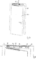
- the in Fig. 1 shown door drive 10 includes a housing 12 having a first mounting surface 14 on a first housing outside and a second mounting surface 16 (FIG. Fig. 3B ) on a second housing outside.
- the first mounting surface 14 and the second mounting surface 16 lie on opposite sides of the housing 12.
- the door drive 10 comprises, as in Fig. 1 It can be seen, an electronic circuit board 18 which extends substantially parallel to the first housing outside and has approximately the inner dimensions of the housing 12. More specifically, the length and width of the electronic board 18 correspond approximately to the length and width of the first housing outside, reduced by the space, which is occupied by a transformer 32 and another short electronic board 34 at the end faces. In the electronic board 18 a plurality of recesses 36 are formed.
- the projecting through the recesses 36 housing sections each have a partial surface 13 of the first mounting surface 14.
- the recesses 36 are formed in corner regions of the electronic board 18, on the sides of the electronic board 18 and in the central region of the electronic board 18.
- the electronic board 18 itself is generally not suitable as a mounting surface, since any mechanical stress on the electronic board 18 should be avoided.
- the door drive comprises a motor, in particular an electric motor, for driving an output shaft 20.
- the output shaft 20 is rotatably mounted in the housing 12 and with a door leaf 22 (FIGS. Fig. 2A and 3A ) or a frame 24 ( Fig. 2A and 3A ) can be coupled or coupled.
- the axis of rotation D of the output shaft 20 is off-center, ie offset along a longitudinal axis L of the housing 12 to the center of the housing 12.
- the housing 12 has in each case a housing opening 26 on the first housing side and the second housing side. These two housing openings 26 allow the output shaft 20 can be selectively coupled at each of its end portions with a lever 28.
- the door drive 10 comprises a not shown displaceable transmission element, in particular a rack, with which a driving force is transmitted from the engine to the output shaft 20.
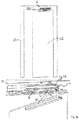
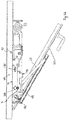
- a spring unit 30 (FIG. Fig. 6B ) is provided, which is tensioned with the door open 22 to drive via the sliding transmission element, the output shaft 20 and thus close the door 22.
- Fig. 2B the electronics-side first mounting surface 14 can be seen and the housing 12 with the transmission-side second mounting surface 16 attached to the frame 24.
- Fig. 3B to see the transmission-side second mounting surface 16 and the housing 12 with the electronics-side first mounting surface 14 attached to the frame 24.
- Fig. 4A shows the door drive 10 electronics side, ie as in Fig. 3B , bolted to the frame 24 while Fig. 4B the door drive 10 on the transmission side, ie as in Fig. 2B , screwed to the frame 24 shows.
- 12 mounting openings 42 are provided in the housing consisting of two separate housing parts. Each of the mounting openings 42 has two opposite, annular abutment surfaces 44. The screws 38 can so once from the left ( Fig. 4A ) and once from the right ( Fig. 4B ) are inserted through the housing 12 to attach the housing 12 and thus the door drive 10 in different ways either on the electronics side or the transmission side to the frame 24.
- the mounting holes 42 are arranged in alignment with the previously described recesses 36 of the electronic board 18.
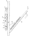
- FIGS. 5A and 5B show the electronic board 18 which is electrically connected to one or more angle plugs, not shown, with the short electronic board 34. While the electronics board 18, as in Fig. 1 shown, is mounted substantially parallel to the first housing outside, the short electronic board 34 is substantially parallel to one of the end sides of the housing 12. On the outside of the short electronic board 34 a plurality of plug receptacles 46 are formed, are plugged into the plug 48. These connectors 48 are connected via connecting lines 50 with sensors, not shown.
- the door can be determined via the sensors, for example radar sensors and / or infrared sensors, whether the door should be opened, for example because a person is standing in front of the closed door, or if the door can be closed, for example because no object is in the pivoting range of the door leaf 22 ,
Claims (9)
- Entraînement de porte (10), en particulier entraînement de porte pivotante, comprenant un boîtier (12) qui comprend une première surface de montage (14) au niveau d'un premier côté extérieur de boîtier et une deuxième surface de montage (16) au niveau d'un deuxième côté extérieur de boîtier opposé,
une carte électronique (18) qui est disposée à côté du premier côté extérieur de boîtier et essentiellement parallèlement à celui-ci,
un axe de prise de force (20) supporté de manière rotative dans le boîtier (12) et pouvant être accouplé à un battant de porte (22) ou un châssis dormant (24), l'axe de prise de force (20) étant disposé le long d'un axe longitudinal (L) du boîtier (12) de manière décalée par rapport au milieu du boîtier (12),
un moteur pour l'entraînement de l'axe de prise de force (20), en particulier par le biais d'une crémaillère, et d'une unité de ressort (30) qui, pendant le mouvement d'ouverture respectif du battant de porte (22) est serrée et se détend pendant un mouvement de fermeture respectif du battant de porte (22),
caractérisé
en ce que l'entraînement de porte (10) peut être monté au choix sur la première ou la deuxième surface de montage (14, 16) sur un battant de porte (22) ou un châssis dormant (24),
des évidements (36) étant réalisés dans la carte électronique (18), à travers lesquels pénètre un moyen de fixation respectif (38) qui peut être guidé à travers le boîtier perpendiculairement aux surfaces de montage (14, 16), en particulier une vis, et/ou une portion de boîtier avec au moins une partie (13) d'une surface de montage (14, 16), des ouvertures de montage (42) pour les moyens de fixation (38), continues et accessibles à chaque fois depuis les deux surfaces de montage mutuellement opposées (14, 16), étant prévues dans le boîtier (12), lesquelles sont disposées en affleurement avec les évidements correspondants (36) dans la carte électronique (18). - Entraînement de porte (10) selon la revendication 1,
caractérisé
en ce que le boîtier (12) est pourvu de surfaces d'appui (44) pour les moyens de fixation (38) pouvant être introduits dans les ouvertures de montage (42) pour la fixation de l'entraînement de porte (10) au châssis dormant (24) ou au battant de porte (22). - Entraînement de porte (10) selon au moins l'une des revendications précédentes,
caractérisé
en ce que la première surface de montage (14) du boîtier (12) et/ou la deuxième surface de montage (16) du boîtier (12) se composent d'aux moins deux surfaces partielles séparées (13), en particulier situées dans un plan. - Entraînement de porte (10) selon la revendication 3,
caractérisé
en ce que plusieurs portions de boîtier s'étendent à travers des évidements respectifs (36) de la carte électronique (18) et forment ensemble l'une des surfaces de montage (14, 16) du boîtier (12). - Entraînement de porte (10) selon au moins l'une des revendications précédentes,
caractérisé
en ce que les évidements (36) sont prévus d'une part dans la région de bord de la carte électronique (18) et d'autre part dans la région centrale de la carte électronique (18). - Entraînement de porte (10) selon au moins l'une des revendications précédentes,
caractérisé
en ce qu'une deuxième carte électronique (34) est disposée essentiellement parallèlement à un côté frontal du boîtier (12) et essentiellement perpendiculairement à la première carte électronique (18). - Entraînement de porte (10) selon la revendication 6,
caractérisé
en ce que la première carte électronique (18) et la deuxième carte électronique (34) sont connectées électriquement par le biais d'un connecteur coudé. - Entraînement de porte (10) selon la revendication 6 ou 7,
caractérisé
en ce que la deuxième carte électronique (34) présente au moins une fiche femelle (46) pour la connexion à un système de capteur. - Entraînement de porte (10) selon la revendication 8,
caractérisé
en ce que le système de capteur comprend un capteur radar et/ou un capteur infrarouge.
Priority Applications (1)
| Application Number | Priority Date | Filing Date | Title |
|---|---|---|---|
| PL15162802T PL2933416T3 (pl) | 2014-04-15 | 2015-04-08 | Napęd drzwi |
Applications Claiming Priority (2)
| Application Number | Priority Date | Filing Date | Title |
|---|---|---|---|
| DE102014207217.4A DE102014207217B3 (de) | 2014-04-15 | 2014-04-15 | Drehtürantrieb |
| DE102015202853.4A DE102015202853A1 (de) | 2015-02-17 | 2015-02-17 | Türantrieb |
Publications (2)
| Publication Number | Publication Date |
|---|---|
| EP2933416A1 EP2933416A1 (fr) | 2015-10-21 |
| EP2933416B1 true EP2933416B1 (fr) | 2019-06-05 |
Family
ID=52811069
Family Applications (1)
| Application Number | Title | Priority Date | Filing Date |
|---|---|---|---|
| EP15162802.1A Active EP2933416B1 (fr) | 2014-04-15 | 2015-04-08 | Entraînement de porte |
Country Status (5)
| Country | Link |
|---|---|
| EP (1) | EP2933416B1 (fr) |
| CN (1) | CN105064848B (fr) |
| DK (1) | DK2933416T3 (fr) |
| ES (1) | ES2743220T3 (fr) |
| PL (1) | PL2933416T3 (fr) |
Families Citing this family (1)
| Publication number | Priority date | Publication date | Assignee | Title |
|---|---|---|---|---|
| CN109288476B (zh) * | 2018-09-21 | 2020-06-19 | 珠海格力电器股份有限公司 | 厨电设备及其控制方法 |
Citations (2)
| Publication number | Priority date | Publication date | Assignee | Title |
|---|---|---|---|---|
| DE20320657U1 (de) * | 2003-01-10 | 2004-11-25 | Dorma Gmbh + Co. Kg | Türflügelantrieb |
| US20080236048A1 (en) * | 2007-03-30 | 2008-10-02 | The Stanley Works | Door operating system |
Family Cites Families (5)
| Publication number | Priority date | Publication date | Assignee | Title |
|---|---|---|---|---|
| EP1340877B1 (fr) * | 2002-03-01 | 2016-05-25 | GEZE GmbH | Commande de porte |
| DE10260108B3 (de) * | 2002-12-19 | 2004-09-16 | Geze Gmbh | Freilaufvorrichtung für den Antrieb eines Flügels einer Tür oder eines Fensters |
| WO2008134442A1 (fr) * | 2007-04-24 | 2008-11-06 | Yale Security Inc. | Ferme-porte |
| DE102007030088B4 (de) * | 2007-06-28 | 2012-12-13 | Geze Gmbh | Antrieb zum Betätigen eines beweglichen Flügels, insbesondere einer Tür oder eines Fensters |
| CN201301625Y (zh) * | 2008-11-14 | 2009-09-02 | 盖泽工业(天津)有限公司 | 链式开窗器及具有该链式开窗器的悬开窗 |
-
2015
- 2015-04-08 PL PL15162802T patent/PL2933416T3/pl unknown
- 2015-04-08 EP EP15162802.1A patent/EP2933416B1/fr active Active
- 2015-04-08 DK DK15162802.1T patent/DK2933416T3/da active
- 2015-04-08 ES ES15162802T patent/ES2743220T3/es active Active
- 2015-04-15 CN CN201510409584.2A patent/CN105064848B/zh active Active
Patent Citations (2)
| Publication number | Priority date | Publication date | Assignee | Title |
|---|---|---|---|---|
| DE20320657U1 (de) * | 2003-01-10 | 2004-11-25 | Dorma Gmbh + Co. Kg | Türflügelantrieb |
| US20080236048A1 (en) * | 2007-03-30 | 2008-10-02 | The Stanley Works | Door operating system |
Also Published As
| Publication number | Publication date |
|---|---|
| EP2933416A1 (fr) | 2015-10-21 |
| DK2933416T3 (da) | 2019-08-19 |
| CN105064848A (zh) | 2015-11-18 |
| ES2743220T3 (es) | 2020-02-18 |
| CN105064848B (zh) | 2017-04-26 |
| PL2933416T3 (pl) | 2019-12-31 |
Similar Documents
| Publication | Publication Date | Title |
|---|---|---|
| EP2580819B1 (fr) | Appareil électrique ayant un connecteur et une connexion électrique | |
| DE102005061724B4 (de) | Antrieb zum Betätigen eines beweglichen Flügels, insbesondere einer Tür oder eines Fensters | |
| EP2025847A2 (fr) | Entraînement linéaire pour portes coulissantes ou analogues | |
| EP1568833B1 (fr) | Gâche pour une fenêtre ou une porte | |
| DE102005059383B4 (de) | System zum Ausgleich von Längendifferenzen zwischen einem in eine Öffnung eines Türblattes einzusetzenden Zylinderschloss und dem Türblatt | |
| EP2499320A1 (fr) | Revêtement pour un actionneur de porte | |
| EP2933416B1 (fr) | Entraînement de porte | |
| DE102015202853A1 (de) | Türantrieb | |
| EP1640543A1 (fr) | Dispositif de propulsion pour un élément de séparation coulissant, chariot et élément de séparation | |
| DE202012001208U1 (de) | Betätigungsvorrichtung für ein Fenster oder eine Tür | |
| EP2284346B1 (fr) | Plaque de montage, système et procédé de montage pour agencements d'actionneur de porte | |
| DE4032677C2 (de) | Automatische Türanlage mit motorisch angetriebenen Flügeln | |
| EP0844356B1 (fr) | Dispositif pour la commande d'une fenêtre | |
| EP0341529A2 (fr) | Serrure | |
| DE102013100320A1 (de) | Anordnung an einer Flügelanlage | |
| EP3327228B1 (fr) | Dispositif de verrouillage destiné à verrouiller et à emmener au moins deux éléments en forme de plaque montés en coulissement le long d'une première direction de coulissement et d'une seconde direction de coulissement opposée et système de paroi comprenant au moins deux éléments en forme de plaque | |
| EP2947241A1 (fr) | Serrure à pêne pour un vantail de porte et procédé de montage | |
| DE102014226794A1 (de) | Beschlag zum Einbau zwischen einem Flügel und einem festen Rahmen eines Fensters, einer Tür oder dergleichen sowie Fenster, Tür oder dergleichen mit einem derartigen Beschlag | |
| WO2015040007A1 (fr) | Dispositif d'entraînement de porte et porte pivotante dotée d'un tel dispositif | |
| DE102019107721A1 (de) | Stellantrieb und Verwendung | |
| DE102018109596A1 (de) | Verschließanordnung für einen Schaltschrank und ein entsprechender Adapter | |
| EP1807851B1 (fr) | Accouplement d'arbres, destine en particulier a un commutateur electrique | |
| DE102020206316B4 (de) | Antrieb | |
| DE102011001684A1 (de) | Verdeckt liegendes Türband | |
| DE10147990A1 (de) | Schaltschrank |
Legal Events
| Date | Code | Title | Description |
|---|---|---|---|
| PUAI | Public reference made under article 153(3) epc to a published international application that has entered the european phase |
Free format text: ORIGINAL CODE: 0009012 |
|
| AK | Designated contracting states |
Kind code of ref document: A1 Designated state(s): AL AT BE BG CH CY CZ DE DK EE ES FI FR GB GR HR HU IE IS IT LI LT LU LV MC MK MT NL NO PL PT RO RS SE SI SK SM TR |
|
| AX | Request for extension of the european patent |
Extension state: BA ME |
|
| 17P | Request for examination filed |
Effective date: 20160127 |
|
| RBV | Designated contracting states (corrected) |
Designated state(s): AL AT BE BG CH CY CZ DE DK EE ES FI FR GB GR HR HU IE IS IT LI LT LU LV MC MK MT NL NO PL PT RO RS SE SI SK SM TR |
|
| 17Q | First examination report despatched |
Effective date: 20160713 |
|
| STAA | Information on the status of an ep patent application or granted ep patent |
Free format text: STATUS: EXAMINATION IS IN PROGRESS |
|
| GRAP | Despatch of communication of intention to grant a patent |
Free format text: ORIGINAL CODE: EPIDOSNIGR1 |
|
| STAA | Information on the status of an ep patent application or granted ep patent |
Free format text: STATUS: GRANT OF PATENT IS INTENDED |
|
| INTG | Intention to grant announced |
Effective date: 20181128 |
|
| GRAS | Grant fee paid |
Free format text: ORIGINAL CODE: EPIDOSNIGR3 |
|
| GRAA | (expected) grant |
Free format text: ORIGINAL CODE: 0009210 |
|
| STAA | Information on the status of an ep patent application or granted ep patent |
Free format text: STATUS: THE PATENT HAS BEEN GRANTED |
|
| AK | Designated contracting states |
Kind code of ref document: B1 Designated state(s): AL AT BE BG CH CY CZ DE DK EE ES FI FR GB GR HR HU IE IS IT LI LT LU LV MC MK MT NL NO PL PT RO RS SE SI SK SM TR |
|
| REG | Reference to a national code |
Ref country code: GB Ref legal event code: FG4D Free format text: NOT ENGLISH |
|
| REG | Reference to a national code |
Ref country code: CH Ref legal event code: EP |
|
| REG | Reference to a national code |
Ref country code: AT Ref legal event code: REF Ref document number: 1140134 Country of ref document: AT Kind code of ref document: T Effective date: 20190615 |
|
| REG | Reference to a national code |
Ref country code: IE Ref legal event code: FG4D Free format text: LANGUAGE OF EP DOCUMENT: GERMAN |
|
| REG | Reference to a national code |
Ref country code: DE Ref legal event code: R096 Ref document number: 502015009206 Country of ref document: DE |
|
| REG | Reference to a national code |
Ref country code: DK Ref legal event code: T3 Effective date: 20190816 |
|
| REG | Reference to a national code |
Ref country code: SE Ref legal event code: TRGR |
|
| REG | Reference to a national code |
Ref country code: NO Ref legal event code: T2 Effective date: 20190605 |
|
| REG | Reference to a national code |
Ref country code: NL Ref legal event code: FP |
|
| REG | Reference to a national code |
Ref country code: LT Ref legal event code: MG4D |
|
| PG25 | Lapsed in a contracting state [announced via postgrant information from national office to epo] |
Ref country code: HR Free format text: LAPSE BECAUSE OF FAILURE TO SUBMIT A TRANSLATION OF THE DESCRIPTION OR TO PAY THE FEE WITHIN THE PRESCRIBED TIME-LIMIT Effective date: 20190605 Ref country code: LT Free format text: LAPSE BECAUSE OF FAILURE TO SUBMIT A TRANSLATION OF THE DESCRIPTION OR TO PAY THE FEE WITHIN THE PRESCRIBED TIME-LIMIT Effective date: 20190605 Ref country code: FI Free format text: LAPSE BECAUSE OF FAILURE TO SUBMIT A TRANSLATION OF THE DESCRIPTION OR TO PAY THE FEE WITHIN THE PRESCRIBED TIME-LIMIT Effective date: 20190605 Ref country code: AL Free format text: LAPSE BECAUSE OF FAILURE TO SUBMIT A TRANSLATION OF THE DESCRIPTION OR TO PAY THE FEE WITHIN THE PRESCRIBED TIME-LIMIT Effective date: 20190605 |
|
| PG25 | Lapsed in a contracting state [announced via postgrant information from national office to epo] |
Ref country code: GR Free format text: LAPSE BECAUSE OF FAILURE TO SUBMIT A TRANSLATION OF THE DESCRIPTION OR TO PAY THE FEE WITHIN THE PRESCRIBED TIME-LIMIT Effective date: 20190906 Ref country code: BG Free format text: LAPSE BECAUSE OF FAILURE TO SUBMIT A TRANSLATION OF THE DESCRIPTION OR TO PAY THE FEE WITHIN THE PRESCRIBED TIME-LIMIT Effective date: 20190905 Ref country code: RS Free format text: LAPSE BECAUSE OF FAILURE TO SUBMIT A TRANSLATION OF THE DESCRIPTION OR TO PAY THE FEE WITHIN THE PRESCRIBED TIME-LIMIT Effective date: 20190605 Ref country code: LV Free format text: LAPSE BECAUSE OF FAILURE TO SUBMIT A TRANSLATION OF THE DESCRIPTION OR TO PAY THE FEE WITHIN THE PRESCRIBED TIME-LIMIT Effective date: 20190605 |
|
| PG25 | Lapsed in a contracting state [announced via postgrant information from national office to epo] |
Ref country code: EE Free format text: LAPSE BECAUSE OF FAILURE TO SUBMIT A TRANSLATION OF THE DESCRIPTION OR TO PAY THE FEE WITHIN THE PRESCRIBED TIME-LIMIT Effective date: 20190605 Ref country code: SK Free format text: LAPSE BECAUSE OF FAILURE TO SUBMIT A TRANSLATION OF THE DESCRIPTION OR TO PAY THE FEE WITHIN THE PRESCRIBED TIME-LIMIT Effective date: 20190605 Ref country code: PT Free format text: LAPSE BECAUSE OF FAILURE TO SUBMIT A TRANSLATION OF THE DESCRIPTION OR TO PAY THE FEE WITHIN THE PRESCRIBED TIME-LIMIT Effective date: 20191007 Ref country code: CZ Free format text: LAPSE BECAUSE OF FAILURE TO SUBMIT A TRANSLATION OF THE DESCRIPTION OR TO PAY THE FEE WITHIN THE PRESCRIBED TIME-LIMIT Effective date: 20190605 Ref country code: RO Free format text: LAPSE BECAUSE OF FAILURE TO SUBMIT A TRANSLATION OF THE DESCRIPTION OR TO PAY THE FEE WITHIN THE PRESCRIBED TIME-LIMIT Effective date: 20190605 |
|
| REG | Reference to a national code |
Ref country code: ES Ref legal event code: FG2A Ref document number: 2743220 Country of ref document: ES Kind code of ref document: T3 Effective date: 20200218 |
|
| PG25 | Lapsed in a contracting state [announced via postgrant information from national office to epo] |
Ref country code: IS Free format text: LAPSE BECAUSE OF FAILURE TO SUBMIT A TRANSLATION OF THE DESCRIPTION OR TO PAY THE FEE WITHIN THE PRESCRIBED TIME-LIMIT Effective date: 20191005 Ref country code: SM Free format text: LAPSE BECAUSE OF FAILURE TO SUBMIT A TRANSLATION OF THE DESCRIPTION OR TO PAY THE FEE WITHIN THE PRESCRIBED TIME-LIMIT Effective date: 20190605 |
|
| REG | Reference to a national code |
Ref country code: DE Ref legal event code: R097 Ref document number: 502015009206 Country of ref document: DE |
|
| PG25 | Lapsed in a contracting state [announced via postgrant information from national office to epo] |
Ref country code: TR Free format text: LAPSE BECAUSE OF FAILURE TO SUBMIT A TRANSLATION OF THE DESCRIPTION OR TO PAY THE FEE WITHIN THE PRESCRIBED TIME-LIMIT Effective date: 20190605 |
|
| PLBE | No opposition filed within time limit |
Free format text: ORIGINAL CODE: 0009261 |
|
| STAA | Information on the status of an ep patent application or granted ep patent |
Free format text: STATUS: NO OPPOSITION FILED WITHIN TIME LIMIT |
|
| 26N | No opposition filed |
Effective date: 20200306 |
|
| PG25 | Lapsed in a contracting state [announced via postgrant information from national office to epo] |
Ref country code: SI Free format text: LAPSE BECAUSE OF FAILURE TO SUBMIT A TRANSLATION OF THE DESCRIPTION OR TO PAY THE FEE WITHIN THE PRESCRIBED TIME-LIMIT Effective date: 20190605 |
|
| PG25 | Lapsed in a contracting state [announced via postgrant information from national office to epo] |
Ref country code: MC Free format text: LAPSE BECAUSE OF FAILURE TO SUBMIT A TRANSLATION OF THE DESCRIPTION OR TO PAY THE FEE WITHIN THE PRESCRIBED TIME-LIMIT Effective date: 20190605 |
|
| PG25 | Lapsed in a contracting state [announced via postgrant information from national office to epo] |
Ref country code: LU Free format text: LAPSE BECAUSE OF NON-PAYMENT OF DUE FEES Effective date: 20200408 |
|
| REG | Reference to a national code |
Ref country code: BE Ref legal event code: MM Effective date: 20200430 |
|
| PG25 | Lapsed in a contracting state [announced via postgrant information from national office to epo] |
Ref country code: BE Free format text: LAPSE BECAUSE OF NON-PAYMENT OF DUE FEES Effective date: 20200430 |
|
| PG25 | Lapsed in a contracting state [announced via postgrant information from national office to epo] |
Ref country code: IE Free format text: LAPSE BECAUSE OF NON-PAYMENT OF DUE FEES Effective date: 20200408 |
|
| PG25 | Lapsed in a contracting state [announced via postgrant information from national office to epo] |
Ref country code: MT Free format text: LAPSE BECAUSE OF FAILURE TO SUBMIT A TRANSLATION OF THE DESCRIPTION OR TO PAY THE FEE WITHIN THE PRESCRIBED TIME-LIMIT Effective date: 20190605 Ref country code: CY Free format text: LAPSE BECAUSE OF FAILURE TO SUBMIT A TRANSLATION OF THE DESCRIPTION OR TO PAY THE FEE WITHIN THE PRESCRIBED TIME-LIMIT Effective date: 20190605 |
|
| PG25 | Lapsed in a contracting state [announced via postgrant information from national office to epo] |
Ref country code: MK Free format text: LAPSE BECAUSE OF FAILURE TO SUBMIT A TRANSLATION OF THE DESCRIPTION OR TO PAY THE FEE WITHIN THE PRESCRIBED TIME-LIMIT Effective date: 20190605 |
|
| P01 | Opt-out of the competence of the unified patent court (upc) registered |
Effective date: 20230510 |
|
| PGFP | Annual fee paid to national office [announced via postgrant information from national office to epo] |
Ref country code: NL Payment date: 20230419 Year of fee payment: 9 |
|
| PGFP | Annual fee paid to national office [announced via postgrant information from national office to epo] |
Ref country code: NO Payment date: 20230421 Year of fee payment: 9 Ref country code: IT Payment date: 20230426 Year of fee payment: 9 Ref country code: FR Payment date: 20230424 Year of fee payment: 9 Ref country code: ES Payment date: 20230627 Year of fee payment: 9 Ref country code: DK Payment date: 20230421 Year of fee payment: 9 Ref country code: DE Payment date: 20230430 Year of fee payment: 9 Ref country code: CH Payment date: 20230502 Year of fee payment: 9 |
|
| PGFP | Annual fee paid to national office [announced via postgrant information from national office to epo] |
Ref country code: SE Payment date: 20230420 Year of fee payment: 9 Ref country code: PL Payment date: 20230403 Year of fee payment: 9 Ref country code: AT Payment date: 20230420 Year of fee payment: 9 |
|
| PGFP | Annual fee paid to national office [announced via postgrant information from national office to epo] |
Ref country code: GB Payment date: 20230419 Year of fee payment: 9 |