EP2933416B1 - Door drive - Google Patents
Door drive Download PDFInfo
- Publication number
- EP2933416B1 EP2933416B1 EP15162802.1A EP15162802A EP2933416B1 EP 2933416 B1 EP2933416 B1 EP 2933416B1 EP 15162802 A EP15162802 A EP 15162802A EP 2933416 B1 EP2933416 B1 EP 2933416B1
- Authority
- EP
- European Patent Office
- Prior art keywords
- housing
- door drive
- circuit board
- door
- printed circuit
- Prior art date
- Legal status (The legal status is an assumption and is not a legal conclusion. Google has not performed a legal analysis and makes no representation as to the accuracy of the status listed.)
- Active
Links
Images


Classifications
-
- E—FIXED CONSTRUCTIONS
- E05—LOCKS; KEYS; WINDOW OR DOOR FITTINGS; SAFES
- E05F—DEVICES FOR MOVING WINGS INTO OPEN OR CLOSED POSITION; CHECKS FOR WINGS; WING FITTINGS NOT OTHERWISE PROVIDED FOR, CONCERNED WITH THE FUNCTIONING OF THE WING
- E05F15/00—Power-operated mechanisms for wings
- E05F15/60—Power-operated mechanisms for wings using electrical actuators
- E05F15/603—Power-operated mechanisms for wings using electrical actuators using rotary electromotors
- E05F15/611—Power-operated mechanisms for wings using electrical actuators using rotary electromotors for swinging wings
- E05F15/63—Power-operated mechanisms for wings using electrical actuators using rotary electromotors for swinging wings operated by swinging arms
- E05F2015/631—Power-operated mechanisms for wings using electrical actuators using rotary electromotors for swinging wings operated by swinging arms the end of the arm sliding in a track; Slider arms therefor
-
- E—FIXED CONSTRUCTIONS
- E05—LOCKS; KEYS; WINDOW OR DOOR FITTINGS; SAFES
- E05Y—INDEXING SCHEME RELATING TO HINGES OR OTHER SUSPENSION DEVICES FOR DOORS, WINDOWS OR WINGS AND DEVICES FOR MOVING WINGS INTO OPEN OR CLOSED POSITION, CHECKS FOR WINGS AND WING FITTINGS NOT OTHERWISE PROVIDED FOR, CONCERNED WITH THE FUNCTIONING OF THE WING
- E05Y2400/00—Electronic control; Power supply; Power or signal transmission; User interfaces
- E05Y2400/10—Electronic control
- E05Y2400/30—Electronic control of motors
- E05Y2400/40—Control units therefore
-
- E—FIXED CONSTRUCTIONS
- E05—LOCKS; KEYS; WINDOW OR DOOR FITTINGS; SAFES
- E05Y—INDEXING SCHEME RELATING TO HINGES OR OTHER SUSPENSION DEVICES FOR DOORS, WINDOWS OR WINGS AND DEVICES FOR MOVING WINGS INTO OPEN OR CLOSED POSITION, CHECKS FOR WINGS AND WING FITTINGS NOT OTHERWISE PROVIDED FOR, CONCERNED WITH THE FUNCTIONING OF THE WING
- E05Y2600/00—Mounting or coupling arrangements for elements provided for in this subclass
- E05Y2600/40—Mounting location; Visibility of the elements
- E05Y2600/45—Mounting location; Visibility of the elements in or on the fixed frame
-
- E—FIXED CONSTRUCTIONS
- E05—LOCKS; KEYS; WINDOW OR DOOR FITTINGS; SAFES
- E05Y—INDEXING SCHEME RELATING TO HINGES OR OTHER SUSPENSION DEVICES FOR DOORS, WINDOWS OR WINGS AND DEVICES FOR MOVING WINGS INTO OPEN OR CLOSED POSITION, CHECKS FOR WINGS AND WING FITTINGS NOT OTHERWISE PROVIDED FOR, CONCERNED WITH THE FUNCTIONING OF THE WING
- E05Y2800/00—Details, accessories and auxiliary operations not otherwise provided for
- E05Y2800/15—Applicability
- E05Y2800/17—Universally applicable
- E05Y2800/172—Universally applicable on different wing or frame locations
- E05Y2800/174—Universally applicable on different wing or frame locations on the left or right side
-
- E—FIXED CONSTRUCTIONS
- E05—LOCKS; KEYS; WINDOW OR DOOR FITTINGS; SAFES
- E05Y—INDEXING SCHEME RELATING TO HINGES OR OTHER SUSPENSION DEVICES FOR DOORS, WINDOWS OR WINGS AND DEVICES FOR MOVING WINGS INTO OPEN OR CLOSED POSITION, CHECKS FOR WINGS AND WING FITTINGS NOT OTHERWISE PROVIDED FOR, CONCERNED WITH THE FUNCTIONING OF THE WING
- E05Y2900/00—Application of doors, windows, wings or fittings thereof
- E05Y2900/10—Application of doors, windows, wings or fittings thereof for buildings or parts thereof
- E05Y2900/13—Application of doors, windows, wings or fittings thereof for buildings or parts thereof characterised by the type of wing
- E05Y2900/132—Doors
Definitions
- the present invention relates to a door operator, in particular a revolving door drive, having a housing, which comprises a first mounting surface on a first housing outside and a second mounting surface on an opposite second housing outside, an electronic circuit board, which is adjacent to the first housing outside and arranged substantially parallel thereto is a rotatably mounted in the housing and coupled to a door leaf or a frame output shaft, wherein the output axis is arranged along a longitudinal axis of the housing offset from the center of the housing, a motor for driving the output shaft, in particular via a rack, and a spring unit, which is tensioned during a respective opening movement of the door leaf and relaxes during a respective closing movement of the door leaf.
- Such door drives are used to close the wing of a motorized door with spring force. This is particularly important in smoke and fire doors of importance, which must be closed quickly and reliably in case of alarm, especially after responding to a smoke detector and power failure.
- the spring unit is tensioned at the same time. With the aid of the spring unit, the door drive can thus close the door leaf even in the event of a power failure, which is mandatory with fire doors.
- the spring action on the output shaft can only develop in one direction of rotation.
- the output shaft typically sits off-center in the longitudinal direction of the door drive, ie offset along a longitudinal axis of the housing to the center of the housing, in the range of about 20% of the door drive length.
- two different door drives are required in these models.
- an electronic board is usually arranged within the housing of the door drive. Due to the required size of the electronic board, it is advantageous to arrange the electronic board parallel to the mounting surfaces, since the dimensions of the space of the substantially cuboid door drive are greatest in this direction.
- this creates the problem that the electronic board mounting the door drive on a door or window frame in the way is because fixing screws must pass through the housing and stable contact surfaces are needed on the housing in order to transmit the forces can occur. Therefore, it has been customary to arrange a plurality of electronic boards spaced apart in the housing to provide space between them for the passage of mounting screws for mounting the housing to a door leaf or frame.
- this has the disadvantage that the multiple electronic boards must be connected to each other by ribbon cables, which is complicated and expensive.
- the invention has for its object to provide a door drive, in particular swing door drive of the type mentioned, which despite the electronics board has a small space, in different ways on the door and the window frame is mounted and no complex connection of multiple electronic boards by means of ribbon cables required.
- a respective head mounting a mounting of the door drive on the upper spar of the window frame and under a respective door assembly the mounting of the door drive on the door leaf.
- Under a respective mounting on the hinge side is an assembly of the door drive on the side of the frame or the door to understand on which the bands are provided.
- a respective assembly of the door drive on the hinge opposite side is to be understood as an assembly of the door drive on the side opposite to the hinge side.
- the output shaft can be rotatably connected to a guided linearly movable in a slide sliding arm or lever or with a linkage.
- continuous mounting holes are provided in the housing, and arranged the associated recesses in the electronic board in alignment with the mounting holes. This provides a simple way to mount the housing in different ways on the door leaf and the frame without being inhibited by the electronic board.
- each contact surface may, for example, be annular and be suitable for a screw to bear against the head side in order to fix the housing with the screw on the window frame or door leaf.
- the first mounting surface of the housing and / or the second mounting surface of the housing may consist of at least two, in particular lying in a plane, separate partial surfaces. This has the advantage that the housing can be produced more cost-effectively, because the precise mounting surface to be produced is smaller than with a large mounting surface.
- housing sections may protrude through respective recesses of the electronics board and together form one of the mounting surfaces of the housing. This has the advantage that the recesses in the electronics board can be kept small.
- the recesses may be provided on the one hand in the edge region of the electronic board and on the other hand in the central region of the electronic board.
- the recesses may accordingly be present as a lateral recess. It is also possible that the recesses are in the form of an opening in the electronic circuit board. Special constructive freedom arise when the electronic circuit board has recesses in the form of said side recesses and the openings.
- the door drive may have a second electronic board, which is arranged substantially parallel to a front side of the housing and substantially perpendicular to the first electronic circuit board having the recesses.
- the first electronic circuit board and the second electronic circuit board which is essentially perpendicular to it, are preferably electrically connected via an angle plug.
- Such an angle plug simplifies the connection between the mutually perpendicular electronic boards.
- the second electronic board may have at least one connector receptacle for connection to a sensor system.
- the sensor system may comprise a radar sensor and / or an infrared sensor.
- the connection with a radar sensor and / or an infrared sensor has the advantage that it can be detected with the aid of the sensors, whether an object is in the opening region of the door and whether the door should be opened or not.
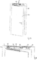
- the in Fig. 1 shown door drive 10 includes a housing 12 having a first mounting surface 14 on a first housing outside and a second mounting surface 16 (FIG. Fig. 3B ) on a second housing outside.
- the first mounting surface 14 and the second mounting surface 16 lie on opposite sides of the housing 12.
- the door drive 10 comprises, as in Fig. 1 It can be seen, an electronic circuit board 18 which extends substantially parallel to the first housing outside and has approximately the inner dimensions of the housing 12. More specifically, the length and width of the electronic board 18 correspond approximately to the length and width of the first housing outside, reduced by the space, which is occupied by a transformer 32 and another short electronic board 34 at the end faces. In the electronic board 18 a plurality of recesses 36 are formed.
- the projecting through the recesses 36 housing sections each have a partial surface 13 of the first mounting surface 14.
- the recesses 36 are formed in corner regions of the electronic board 18, on the sides of the electronic board 18 and in the central region of the electronic board 18.
- the electronic board 18 itself is generally not suitable as a mounting surface, since any mechanical stress on the electronic board 18 should be avoided.
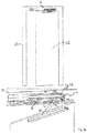
- the door drive comprises a motor, in particular an electric motor, for driving an output shaft 20.
- the output shaft 20 is rotatably mounted in the housing 12 and with a door leaf 22 (FIGS. Fig. 2A and 3A ) or a frame 24 ( Fig. 2A and 3A ) can be coupled or coupled.
- the axis of rotation D of the output shaft 20 is off-center, ie offset along a longitudinal axis L of the housing 12 to the center of the housing 12.
- the housing 12 has in each case a housing opening 26 on the first housing side and the second housing side. These two housing openings 26 allow the output shaft 20 can be selectively coupled at each of its end portions with a lever 28.
- the door drive 10 comprises a not shown displaceable transmission element, in particular a rack, with which a driving force is transmitted from the engine to the output shaft 20.
- a spring unit 30 (FIG. Fig. 6B ) is provided, which is tensioned with the door open 22 to drive via the sliding transmission element, the output shaft 20 and thus close the door 22.
- Fig. 2B the electronics-side first mounting surface 14 can be seen and the housing 12 with the transmission-side second mounting surface 16 attached to the frame 24.
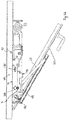
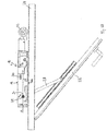
- Fig. 3B to see the transmission-side second mounting surface 16 and the housing 12 with the electronics-side first mounting surface 14 attached to the frame 24.
- Fig. 4A shows the door drive 10 electronics side, ie as in Fig. 3B , bolted to the frame 24 while Fig. 4B the door drive 10 on the transmission side, ie as in Fig. 2B , screwed to the frame 24 shows.
- 12 mounting openings 42 are provided in the housing consisting of two separate housing parts. Each of the mounting openings 42 has two opposite, annular abutment surfaces 44. The screws 38 can so once from the left ( Fig. 4A ) and once from the right ( Fig. 4B ) are inserted through the housing 12 to attach the housing 12 and thus the door drive 10 in different ways either on the electronics side or the transmission side to the frame 24.
- the mounting holes 42 are arranged in alignment with the previously described recesses 36 of the electronic board 18.
- FIGS. 5A and 5B show the electronic board 18 which is electrically connected to one or more angle plugs, not shown, with the short electronic board 34. While the electronics board 18, as in Fig. 1 shown, is mounted substantially parallel to the first housing outside, the short electronic board 34 is substantially parallel to one of the end sides of the housing 12. On the outside of the short electronic board 34 a plurality of plug receptacles 46 are formed, are plugged into the plug 48. These connectors 48 are connected via connecting lines 50 with sensors, not shown.
- the door can be determined via the sensors, for example radar sensors and / or infrared sensors, whether the door should be opened, for example because a person is standing in front of the closed door, or if the door can be closed, for example because no object is in the pivoting range of the door leaf 22 ,
Description
Die vorliegende Erfindung betrifft einen Türantrieb, insbesondere einen Drehtürantrieb, mit einem Gehäuse, das eine erste Montagefläche an einer ersten Gehäuseaußenseite und eine zweite Montagefläche an einer entgegengesetzten zweiten Gehäuseaußenseite umfasst, einer Elektronikplatine, die benachbart zu der ersten Gehäuseaußenseite und im Wesentlichen parallel zu dieser angeordnet ist, einer verdrehbar in dem Gehäuse gelagerten und mit einem Türflügel oder einem Blendrahmen koppelbaren Abtriebsachse, wobei die Abtriebsachse entlang einer Längsachse des Gehäuses versetzt zur Mitte des Gehäuses angeordnet ist, einem Motor zum Antreiben der Abtriebsachse, insbesondere über eine Zahnstange, und eine Federeinheit, die während einer jeweiligen Öffnungsbewegung des Türflügels gespannt wird und sich während einer jeweiligen Schließbewegung des Türflügels entspannt.The present invention relates to a door operator, in particular a revolving door drive, having a housing, which comprises a first mounting surface on a first housing outside and a second mounting surface on an opposite second housing outside, an electronic circuit board, which is adjacent to the first housing outside and arranged substantially parallel thereto is a rotatably mounted in the housing and coupled to a door leaf or a frame output shaft, wherein the output axis is arranged along a longitudinal axis of the housing offset from the center of the housing, a motor for driving the output shaft, in particular via a rack, and a spring unit, which is tensioned during a respective opening movement of the door leaf and relaxes during a respective closing movement of the door leaf.
Türantriebe ähnlicher Art werden in der
Derartige Türantriebe dienen dazu, den Flügel einer motorisch geöffneten Tür mit Federkraft zu schließen. Dies ist insbesondere bei Rauch- und Feuerschutztüren von Bedeutung, die im Alarmfall, insbesondere nach Ansprechen eines Rauchmelders und bei Stromausfall, schnell und zuverlässig geschlossen werden müssen. Mit dem Öffnen des Türflügels wird gleichzeitig die Federeinheit gespannt. Mit Hilfe der Federeinheit kann der Türantrieb den Türflügel somit auch bei einem Stromausfall schließen, was bei Brandschutztüren zwingend ist.Such door drives are used to close the wing of a motorized door with spring force. This is particularly important in smoke and fire doors of importance, which must be closed quickly and reliably in case of alarm, especially after responding to a smoke detector and power failure. By opening the door leaf, the spring unit is tensioned at the same time. With the aid of the spring unit, the door drive can thus close the door leaf even in the event of a power failure, which is mandatory with fire doors.
Bei Drehtürantrieben mit Zahnstange kann sich die Federwirkung an der Abtriebsachse nur in eine Drehrichtung entwickeln. Die Abtriebsachse sitzt typischerweise in Längsrichtung des Türantriebs außermittig, d.h. entlang einer Längsachse des Gehäuses versetzt zur Mitte des Gehäuses, im Bereich von etwa 20% der Türantriebslänge. Für unterschiedliche Montagearten an der Tür sind daher bei diesen Modellen bisher zwei verschiedene Türantriebe erforderlich.For swing door drives with rack, the spring action on the output shaft can only develop in one direction of rotation. The output shaft typically sits off-center in the longitudinal direction of the door drive, ie offset along a longitudinal axis of the housing to the center of the housing, in the range of about 20% of the door drive length. For different types of mounting on the door so far, therefore, two different door drives are required in these models.
Zur Steuerung des Türantriebs ist in der Regel eine Elektronikplatine innerhalb des Gehäuses des Türantriebs angeordnet. Auf Grund der benötigten Größe der Elektronikplatine ist es vorteilhaft, die Elektronikplatine parallel zu den Montageflächen anzuordnen, da die Ausmaße des Bauraums des im Wesentlichen quaderförmigen Türantriebs in dieser Richtung am größten sind. Hierdurch entsteht jedoch die Problematik, dass die Elektronikplatine der Montage des Türantriebs an einem Türflügel oder Blendrahmen im Wege steht, da Befestigungsschrauben das Gehäuse durchgreifen müssen und stabile Anlageflächen am Gehäuse benötigt werden, um die auftretenden Kräfte übertragen zu können. Daher war es bisher üblich, mehrere Elektronikplatinen voneinander beabstandet in dem Gehäuse anzuordnen, um zwischen ihnen Platz für die Hindurchführung von Befestigungsschrauben für die Montage des Gehäuses an einem Türflügel oder Blendrahmen zu schaffen. Dies hat jedoch den Nachteil, dass die mehreren Elektronikplatinen durch Flachbandkabel miteinander verbunden werden müssen, was aufwendig und teuer ist.To control the door drive an electronic board is usually arranged within the housing of the door drive. Due to the required size of the electronic board, it is advantageous to arrange the electronic board parallel to the mounting surfaces, since the dimensions of the space of the substantially cuboid door drive are greatest in this direction. However, this creates the problem that the electronic board mounting the door drive on a door or window frame in the way is because fixing screws must pass through the housing and stable contact surfaces are needed on the housing in order to transmit the forces can occur. Therefore, it has been customary to arrange a plurality of electronic boards spaced apart in the housing to provide space between them for the passage of mounting screws for mounting the housing to a door leaf or frame. However, this has the disadvantage that the multiple electronic boards must be connected to each other by ribbon cables, which is complicated and expensive.
Der Erfindung liegt die Aufgabe zugrunde, einen Türantrieb, insbesondere Drehtürantrieb der eingangs genannten Art anzugeben, der trotz der Elektronikplatine einen geringen Bauraum aufweist, auf unterschiedliche Weise am Türflügel und am Blendrahmen montierbar ist und keine aufwendige Verbindung mehrerer Elektronikplatinen mittels Flachbandkabeln erfordert.The invention has for its object to provide a door drive, in particular swing door drive of the type mentioned, which despite the electronics board has a small space, in different ways on the door and the window frame is mounted and no complex connection of multiple electronic boards by means of ribbon cables required.
Die Aufgabe wird erfindungsgemäß durch einen Türantrieb mit den Merkmalen des Anspruchs 1 gelöst. Bevorzugte Ausführungsformen des erfindungsgemäßen Türantriebs ergeben sich aus den Unteransprüchen, der vorliegenden Beschreibung sowie den Zeichnungen.The object is achieved by a door drive with the features of claim 1. Preferred embodiments of the door drive according to the invention will become apparent from the dependent claims, the present description and the drawings.
Die Problematik, dass Bauraum bereitgestellt werden muss, um zum einen ausreichend stabile Montageflächen zu schaffen und zum anderen Befestigungsmittel senkrecht zu den Montageflächen durch das Gehäuse führen zu können, wird dadurch gelöst, dass in der Elektronikplatine Aussparungen vorgesehen sind. Hierdurch kann der Bauraum im Gehäuse des Türantriebs bestmöglich ausgenutzt werden, ohne auf eine der folgenden sechs Montagearten zu verzichten:
- 1. Kopfmontage-Bandseite-Gleitschiene
- 2. Kopfmontage-Bandgegenseite-Gleitschiene
- 3. Türmontage-Bandseite-Gleitschiene
- 4. Türmontage-Bandgegenseite-Gleitschiene
- 5. Kopfmontage-Bandgegenseite-Gestänge
- 6. Türmontage-Bandseite-Gestänge
- 1. Head mounting band side slide rail
- 2. Head Mount Band Side Slide Rail
- 3. Door Mounting Band Side Slide Rail
- 4. door mounting hinge side slide rail
- 5. Head-mounting band-counter linkage
- 6. Door mounting hinge side linkage
Dabei ist unter einer jeweiligen Kopfmontage eine Montage des Türantriebs am oberen Holm des Blendrahmens und unter einer jeweiligen Türmontage die Montage des Türantriebs an dem Türflügel zu verstehen. Unter einer jeweiligen Montage auf der Bandseite ist eine Montage des Türantriebs auf der Seite des Blendrahmens bzw. des Türflügels zu verstehen, auf der die Bänder vorgesehen sind. Entsprechend ist unter einer jeweiligen Montage des Türantriebs auf der Bandgegenseite eine Montage des Türantriebs auf der Seite zu verstehen, die der Bandseite gegenüberliegt. Schließlich kann die Abtriebsachse mit einem linear beweglich in einer Gleitschiene geführten Gleitarm oder Hebel oder mit einem Gestänge drehfest verbunden sein.It is to be understood by a respective head mounting a mounting of the door drive on the upper spar of the window frame and under a respective door assembly, the mounting of the door drive on the door leaf. Under a respective mounting on the hinge side is an assembly of the door drive on the side of the frame or the door to understand on which the bands are provided. Accordingly, a respective assembly of the door drive on the hinge opposite side is to be understood as an assembly of the door drive on the side opposite to the hinge side. Finally, the output shaft can be rotatably connected to a guided linearly movable in a slide sliding arm or lever or with a linkage.
Erfindungsgemäß sind in dem Gehäuse durchgängige Montageöffnungen vorgesehen, und die zugehörigen Aussparungen in der Elektronikplatine fluchtend zu den Montageöffnungen angeordnet. Dadurch wird eine einfache Möglichkeit geschaffen, das Gehäuse auf unterschiedliche Weise am Türflügel und am Blendrahmen zu montieren, ohne durch die Elektronikplatine gehemmt zu werden.According to the invention continuous mounting holes are provided in the housing, and arranged the associated recesses in the electronic board in alignment with the mounting holes. This provides a simple way to mount the housing in different ways on the door leaf and the frame without being inhibited by the electronic board.
Von Vorteil ist dabei, wenn das Gehäuse mit Anlageflächen für zur Befestigung des Türantriebs am Blendrahmen bzw. am Türflügel in die Montageöffnungen einbringbare Befestigungsmittel versehen ist. Jede Anlagefläche kann beispielsweise ringförmig ausgebildet und dazu geeignet sein, dass eine Schraube kopfseitig an ihr anliegt, um das Gehäuse mit der Schraube an dem Blendrahmen bzw. Türflügel zu befestigen.It is advantageous if the housing is provided with contact surfaces for attaching the door drive on the frame or on the door in the mounting holes insertable fasteners. Each contact surface may, for example, be annular and be suitable for a screw to bear against the head side in order to fix the housing with the screw on the window frame or door leaf.
Die erste Montagefläche des Gehäuses und/oder die zweite Montagefläche des Gehäuses können aus mindestens zwei, insbesondere in einer Ebene liegenden, separaten Teilflächen bestehen. Dies hat den Vorteil, dass das Gehäuse kostengünstiger hergestellt werden kann, weil die präzise zu fertigende Montagefläche kleiner ist als bei einer großen Montagefläche.The first mounting surface of the housing and / or the second mounting surface of the housing may consist of at least two, in particular lying in a plane, separate partial surfaces. This has the advantage that the housing can be produced more cost-effectively, because the precise mounting surface to be produced is smaller than with a large mounting surface.
Es können mehrere Gehäuseabschnitte durch jeweilige Aussparungen der Elektronikplatine hindurchragen und zusammen eine der Montageflächen des Gehäuses bilden. Dies hat den Vorteil, dass die Aussparungen in der Elektronikplatine klein gehalten werden können.Several housing sections may protrude through respective recesses of the electronics board and together form one of the mounting surfaces of the housing. This has the advantage that the recesses in the electronics board can be kept small.
Die Aussparungen können einerseits im Randbereich der Elektronikplatine und andererseits im mittleren Bereich der Elektronikplatine vorgesehen sein. Die Aussparungen können demgemäß als seitliche Ausnehmung vorliegen. Es ist auch möglich, dass die Aussparungen in Form einer Öffnung in der Elektronikplatine vorliegen. Besondere konstruktive Freiheiten ergeben sich, wenn die Elektronikplatine Aussparungen in Form der genannten seitlichen Ausnehmungen und der Öffnungen aufweist.The recesses may be provided on the one hand in the edge region of the electronic board and on the other hand in the central region of the electronic board. The recesses may accordingly be present as a lateral recess. It is also possible that the recesses are in the form of an opening in the electronic circuit board. Special constructive freedom arise when the electronic circuit board has recesses in the form of said side recesses and the openings.
Um eine gute Zugänglichkeit und damit Anschlussmöglichkeit für elektronische Komponenten am Türantrieb vorzusehen, kann der Türantrieb eine zweite Elektronikplatine aufweisen, die im Wesentlichen parallel zu einer Stirnseite des Gehäuses und im Wesentlichen senkrecht zu der ersten Elektronikplatine, die die Aussparungen aufweist, angeordnet ist. Somit kann, egal an welcher der beiden Montageflächen der Türantrieb am Türflügel bzw. Blendrahmen anliegt, sichergestellt werden, dass die parallel zur Stirnseite liegende Elektronikplatine leicht zugänglich ist.To provide good accessibility and thus connectivity for electronic components on the door drive, the door drive may have a second electronic board, which is arranged substantially parallel to a front side of the housing and substantially perpendicular to the first electronic circuit board having the recesses. Thus, no matter which of the two mounting surfaces of the door drive rests on the door leaf or frame, it can be ensured that the electronic board lying parallel to the front side is easily accessible.
Bevorzugter Weise sind die erste Elektronikplatine und die zu ihr im Wesentlichen senkrecht stehende zweite Elektronikplatine über einen Winkelstecker elektrisch verbunden. Ein solcher Winkelstecker vereinfacht die Verbindung zwischen den zueinander senkrecht stehenden Elektronikplatinen.The first electronic circuit board and the second electronic circuit board, which is essentially perpendicular to it, are preferably electrically connected via an angle plug. Such an angle plug simplifies the connection between the mutually perpendicular electronic boards.
Die zweite Elektronikplatine, kann mindestens eine Steckeraufnahme zum Verbinden mit einer Sensorik aufweisen. Dabei kann die Steckeraufnahme auf der Außenseite der Elektronikplatine, also der Seite, die von der Mitte des Gehäuses abgewandt liegt, so ausgerichtet sein, dass auf einfache Weise ein Stecker in die Steckeraufnahme gesteckt werden kann.The second electronic board may have at least one connector receptacle for connection to a sensor system. In this case, the connector receptacle on the outside of the electronic board, so the side facing away from the center of the housing, be aligned so that a plug can be plugged into the connector receptacle in a simple manner.
Beispielsweise kann die Sensorik einen Radarsensor und/oder einen Infrarotsensor umfassen. Die Verbindung mit einem Radarsensor und/oder einem Infrarotsensor hat den Vorteil, dass mit Hilfe der Sensoren erkannt werden kann, ob sich ein Objekt im Öffnungsbereich der Tür befindet und ob die Tür geöffnet werden soll oder nicht.For example, the sensor system may comprise a radar sensor and / or an infrared sensor. The connection with a radar sensor and / or an infrared sensor has the advantage that it can be detected with the aid of the sensors, whether an object is in the opening region of the door and whether the door should be opened or not.
Aufgrund der erfindungsgemäßen Lösung ist für sämtliche zuvor genannten Ausführungsformen nur ein einziger Türantrieb bzw. Drehtürantrieb erforderlich.Due to the solution according to the invention only a single door drive or swing door drive is required for all the aforementioned embodiments.
Die Erfindung wird im Folgenden anhand eines Ausführungsbeispiels unter Bezugnahme auf die Zeichnungen näher erläutert; in diesen schematischen Zeichnungen zeigen:
- Fig. 1
- eine perspektivische Darstellung einer Ausführungsform eines erfindungsgemäßen Türantriebs,
- Fig. 2A
- eine perspektivische Darstellung einer Tür mit dem Türantrieb gemäß
Fig. 1 im nach der Montageart "Kopfmontage-Bandseite-Gleitschiene" montierten Zustand, - Fig. 2B
- eine perspektivische Detailansicht des Türantrieb aus
Fig. 2A , - Fig. 3A
- eine perspektivische Darstellung einer Tür mit dem Türantrieb gemäß
Fig. 1 im nach der Montageart "Kopfmontage-Bandgegenseite-Gleitschiene" montierten Zustand, - Fig. 3B
- eine perspektivische Detailansicht des Türantrieb aus
Fig. 3A , - Fig. 4A
- eine Querschnittsdarstellung des Türantriebs gemäß
Fig. 1 , wobei der Türantrieb an einer elektronikseitigen Montagefläche montiert ist, - Fig. 4B
- eine Querschnittsdarstellung des Türantriebs gemäß
Fig. 1 , wobei der Türantrieb an einer getriebeseitigen Montagefläche montiert ist, - Fig. 5A
- eine perspektivische Darstellung von zwei zueinander senkrecht angeordneten Elektronikplatinen,
- Fig. 5B
- eine Detailansicht aus
Fig. 5A , - Fig. 6A
- eine Draufsicht des Türantriebs gemäß
Fig. 1 in nach Montageart "Kopfmontage-Bandseite-Gleitschiene" montierten Zustand und - Fig. 6B
- eine Draufsicht des Türantriebs gemäß
Fig. 1 in nach Montageart "Kopfmontage-Bandgegenseite-Gleitschiene" montierten Zustand.
- Fig. 1
- a perspective view of an embodiment of a door drive according to the invention,
- Fig. 2A
- a perspective view of a door with the door drive according to
Fig. 1 in the mounted according to the mounting method "head mounting hinge side slide rail" state, - Fig. 2B
- a detailed perspective view of the door drive
Fig. 2A . - Fig. 3A
- a perspective view of a door with the door drive according to
Fig. 1 in the mounted according to the mounting method "head-mounting band-side slide" state, - Fig. 3B
- a detailed perspective view of the door drive
Fig. 3A . - Fig. 4A
- a cross-sectional view of the door drive according to
Fig. 1 in which the door drive is mounted on an electronics-side mounting surface, - Fig. 4B
- a cross-sectional view of the door drive according to
Fig. 1 wherein the door drive is mounted on a transmission-side mounting surface, - Fig. 5A
- a perspective view of two mutually perpendicular electronic boards,
- Fig. 5B
- a detailed view
Fig. 5A . - Fig. 6A
- a plan view of the door drive according to
Fig. 1 in mounted according to mounting method "head mounting hinge side slide rail" state and - Fig. 6B
- a plan view of the door drive according to
Fig. 1 in the mounted according to the mounting method "head-mounted hinge side slide" state.
Der in
Neben der beschriebenen Elektronikplatine 18 umfasst der Türantrieb einen Motor, insbesondere einen Elektromotor, zum Antreiben einer Abtriebsachse 20. Die Abtriebsachse 20 ist verdrehbar in dem Gehäuse 12 gelagert und mit einem Türflügel 22 (
Zusätzlich umfasst der Türantrieb 10 ein nicht gezeigtes verschiebbares Übertragungselement, insbesondere eine Zahnstange, mit der eine Antriebskraft von dem Motor auf die Abtriebsachse 20 übertragen wird. Für den Fall eines Stromausfalls ist eine Federeinheit 30 (
In
Die
Die
- 10
- Türantrieb
- 12
- Gehäuse
- 13
- Teilmontagefläche
- 14
- erste Montagefläche
- 16
- zweite Montagefläche
- 18
- Elektronikplatine
- 20
- Abtriebsachse
- 22
- Türflügel
- 24
- Blendrahmen
- 26
- Gehäuseöffnung
- 28
- Hebel
- 30
- Federeinheit
- 32
- Transformator
- 34
- Elektronikplatine
- 36
- Aussparung
- 38
- Befestigungsmittel
- 42
- Montageöffnung
- 44
- Anlagefläche
- 46
- Steckeraufnahme
- 48
- Stecker
- 50
- Anschlussleitungen
- D
- Drehachse
- L
- Längsachse
- 10
- door drive
- 12
- casing
- 13
- Part mounting surface
- 14
- first mounting surface
- 16
- second mounting surface
- 18
- electronic board
- 20
- output shaft
- 22
- door
- 24
- frame
- 26
- housing opening
- 28
- lever
- 30
- spring unit
- 32
- transformer
- 34
- electronic board
- 36
- recess
- 38
- fastener
- 42
- mounting hole
- 44
- contact surface
- 46
- plug receptacle
- 48
- plug
- 50
- connecting cables
- D
- axis of rotation
- L
- longitudinal axis
Claims (9)
- Door drive (10), in particular swing door drive, having a housing (12) which comprises a first mounting surface (14) on a first housing outer side and a second mounting surface (16) on an opposite second housing outer side; an electronic printed circuit board (18) which is arranged adjacently to the first housing outer side and substantially parallel thereto; an output shaft (20) which is mounted rotatably in the housing (12) and can be coupled to a door leaf (22) or a fixed frame (24), wherein the output shaft (20) is arranged with an offset to the centre of the housing (12) along a longitudinal axis (L) of the housing (12); and a motor for driving the output shaft (20), in particular via a rack, and a spring unit (30) which is tensioned during a respective opening movement of the door leaf (22) and relaxes during a respective closing movement of the door leaf (22),
characterized
in that the door drive (10) can be mounted selectively on the first or second mounting surface (14, 16) on a door leaf (22) or a fixed frame (24), wherein cutouts (36) are formed in the electronic printed circuit board (18), through each of which cutouts there projects a fastening means (38), which can be guided perpendicularly to the mounting surfaces (14, 16) through the housing, in particular a screw, and/or a housing portion having at least one part (13) of a mounting surface (14, 16), wherein continuous mounting openings (42) for the fastening means (38) that are each accessible from both of the mutually opposite mounting surfaces (14, 16) are provided in the housing (12) and are arranged in alignment with the corresponding cutouts (36) in the electronic printed circuit board (18). - Door drive (10) according to Claim 1,
characterized
in that the housing (12) is provided with bearing surfaces (44) for the fastening means (38) which can be introduced into the mounting openings (42) for fastening the door drive (10) to the fixed frame (24) or to the door leaf (22). - Door drive (10) according to at least one of the preceding claims,
characterized
in that the first mounting surface (14) of the housing (12) and/or the second mounting surface (16) of the housing (12) consist or consists of at least two separate partial surfaces (13) which lie in particular in one plane. - Door drive (10) according to Claim 3,
characterized
in that a plurality of housing portions project through respective cutouts (36) of the electronic printed circuit board (18) and together form one of the mounting surfaces (14, 16) of the housing (12) . - Door drive (10) according to at least one of the preceding claims,
characterized
in that the cutouts (36) are provided, on the one hand, in the edge region of the electronic printed circuit board (18) and, on the other hand, in the central region of the electronic printed circuit board (18). - Door drive (10) according to at least one of the preceding claims,
characterized
in that a second electronic printed circuit board (34) is arranged substantially parallel to an end side of the housing (12) and substantially perpendicularly to the first electronic printed circuit board (18). - Door drive (10) according to Claim 6,
characterized
in that the first electronic printed circuit board (18) and the second electronic printed circuit board (34) are electrically connected via an angle plug. - Door drive (10) according to Claim 6 or 7,
characterized
in that the second electronic printed circuit board (34) has at least one plug socket (46) for connection to a sensor system. - Door drive (10) according to Claim 8,
characterized
in that the sensor system comprises a radar sensor and/or an infrared sensor.
Priority Applications (1)
| Application Number | Priority Date | Filing Date | Title |
|---|---|---|---|
| PL15162802T PL2933416T3 (en) | 2014-04-15 | 2015-04-08 | Door drive |
Applications Claiming Priority (2)
| Application Number | Priority Date | Filing Date | Title |
|---|---|---|---|
| DE102014207217.4A DE102014207217B3 (en) | 2014-04-15 | 2014-04-15 | Swing door drive |
| DE102015202853.4A DE102015202853A1 (en) | 2015-02-17 | 2015-02-17 | door drive |
Publications (2)
| Publication Number | Publication Date |
|---|---|
| EP2933416A1 EP2933416A1 (en) | 2015-10-21 |
| EP2933416B1 true EP2933416B1 (en) | 2019-06-05 |
Family
ID=52811069
Family Applications (1)
| Application Number | Title | Priority Date | Filing Date |
|---|---|---|---|
| EP15162802.1A Active EP2933416B1 (en) | 2014-04-15 | 2015-04-08 | Door drive |
Country Status (5)
| Country | Link |
|---|---|
| EP (1) | EP2933416B1 (en) |
| CN (1) | CN105064848B (en) |
| DK (1) | DK2933416T3 (en) |
| ES (1) | ES2743220T3 (en) |
| PL (1) | PL2933416T3 (en) |
Families Citing this family (1)
| Publication number | Priority date | Publication date | Assignee | Title |
|---|---|---|---|---|
| CN109288476B (en) * | 2018-09-21 | 2020-06-19 | 珠海格力电器股份有限公司 | Kitchen electrical appliance and control method thereof |
Citations (2)
| Publication number | Priority date | Publication date | Assignee | Title |
|---|---|---|---|---|
| DE20320657U1 (en) * | 2003-01-10 | 2004-11-25 | Dorma Gmbh + Co. Kg | Hydraulic door leaf drive has system bearer on which door closer and further components are arranged; closer is attached to system bearer so its drive axle is very close to one end of system bearer |
| US20080236048A1 (en) * | 2007-03-30 | 2008-10-02 | The Stanley Works | Door operating system |
Family Cites Families (5)
| Publication number | Priority date | Publication date | Assignee | Title |
|---|---|---|---|---|
| CN1291127C (en) * | 2002-03-01 | 2006-12-20 | 盖慈有限公司 | Transfer mechanism |
| DE10260108B3 (en) * | 2002-12-19 | 2004-09-16 | Geze Gmbh | Freewheel device for driving a wing of a door or a window |
| CA2842521C (en) * | 2007-04-24 | 2017-03-07 | Yale Security Inc. | Door closer assembly |
| DE102007030088B4 (en) * | 2007-06-28 | 2012-12-13 | Geze Gmbh | Drive for actuating a movable wing, in particular a door or a window |
| CN201301625Y (en) * | 2008-11-14 | 2009-09-02 | 盖泽工业(天津)有限公司 | Chain window opener and hung window with same |
-
2015
- 2015-04-08 PL PL15162802T patent/PL2933416T3/en unknown
- 2015-04-08 EP EP15162802.1A patent/EP2933416B1/en active Active
- 2015-04-08 DK DK15162802.1T patent/DK2933416T3/en active
- 2015-04-08 ES ES15162802T patent/ES2743220T3/en active Active
- 2015-04-15 CN CN201510409584.2A patent/CN105064848B/en active Active
Patent Citations (2)
| Publication number | Priority date | Publication date | Assignee | Title |
|---|---|---|---|---|
| DE20320657U1 (en) * | 2003-01-10 | 2004-11-25 | Dorma Gmbh + Co. Kg | Hydraulic door leaf drive has system bearer on which door closer and further components are arranged; closer is attached to system bearer so its drive axle is very close to one end of system bearer |
| US20080236048A1 (en) * | 2007-03-30 | 2008-10-02 | The Stanley Works | Door operating system |
Also Published As
| Publication number | Publication date |
|---|---|
| PL2933416T3 (en) | 2019-12-31 |
| DK2933416T3 (en) | 2019-08-19 |
| ES2743220T3 (en) | 2020-02-18 |
| CN105064848B (en) | 2017-04-26 |
| EP2933416A1 (en) | 2015-10-21 |
| CN105064848A (en) | 2015-11-18 |
Similar Documents
| Publication | Publication Date | Title |
|---|---|---|
| EP2580819B1 (en) | Electrical apparatus with a connector and an electrical connection | |
| DE102005061724B4 (en) | Drive for actuating a movable wing, in particular a door or a window | |
| EP2025847A2 (en) | Linear drive for sliding doors or similar | |
| EP1568833B1 (en) | Striker plate for a window or a door | |
| EP1795675A2 (en) | Device for compensation of length difference between a lock cylinder and a door | |
| EP2499320A1 (en) | Covering for a door operator | |
| EP2933416B1 (en) | Door drive | |
| DE102015202853A1 (en) | door drive | |
| EP1640543A1 (en) | Driving device for a displaceable divider element, running gear and divider element | |
| DE202012001208U1 (en) | Actuating device for a window or a door | |
| EP2284346B1 (en) | Mounting plate, mounting system and method for door actuator assemblies | |
| WO2015040007A1 (en) | Door-driving device and rotating door provided therewith | |
| DE4032677C2 (en) | Automatic door system with motor-driven leaves | |
| DE2527843C2 (en) | Swing door drive | |
| EP0844356B1 (en) | Device for operating a window | |
| EP0341529A2 (en) | Cocking device | |
| DE102013100320A1 (en) | Arrangement on a wing system | |
| EP2947241A1 (en) | Bolt lock for the door leaf of a door and method of installing such a device | |
| DE102014226794A1 (en) | Fitting for installation between a wing and a fixed frame of a window, a door or the like and window, door or the like with such a fitting | |
| DE102019107721A1 (en) | Actuator and use | |
| EP2851656A1 (en) | Housing for a sensor | |
| DE102018109596A1 (en) | Closing arrangement for a control cabinet and a corresponding adapter | |
| DE102020206316B4 (en) | DRIVE | |
| DE102011001684A1 (en) | Hinge for pivotable connection of door leaf with door frame, has auxiliary coupling portions that are movably supported at frame side and door leaf side coupling portions | |
| DE10147990A1 (en) | switch cabinet |
Legal Events
| Date | Code | Title | Description |
|---|---|---|---|
| PUAI | Public reference made under article 153(3) epc to a published international application that has entered the european phase |
Free format text: ORIGINAL CODE: 0009012 |
|
| AK | Designated contracting states |
Kind code of ref document: A1 Designated state(s): AL AT BE BG CH CY CZ DE DK EE ES FI FR GB GR HR HU IE IS IT LI LT LU LV MC MK MT NL NO PL PT RO RS SE SI SK SM TR |
|
| AX | Request for extension of the european patent |
Extension state: BA ME |
|
| 17P | Request for examination filed |
Effective date: 20160127 |
|
| RBV | Designated contracting states (corrected) |
Designated state(s): AL AT BE BG CH CY CZ DE DK EE ES FI FR GB GR HR HU IE IS IT LI LT LU LV MC MK MT NL NO PL PT RO RS SE SI SK SM TR |
|
| 17Q | First examination report despatched |
Effective date: 20160713 |
|
| STAA | Information on the status of an ep patent application or granted ep patent |
Free format text: STATUS: EXAMINATION IS IN PROGRESS |
|
| GRAP | Despatch of communication of intention to grant a patent |
Free format text: ORIGINAL CODE: EPIDOSNIGR1 |
|
| STAA | Information on the status of an ep patent application or granted ep patent |
Free format text: STATUS: GRANT OF PATENT IS INTENDED |
|
| INTG | Intention to grant announced |
Effective date: 20181128 |
|
| GRAS | Grant fee paid |
Free format text: ORIGINAL CODE: EPIDOSNIGR3 |
|
| GRAA | (expected) grant |
Free format text: ORIGINAL CODE: 0009210 |
|
| STAA | Information on the status of an ep patent application or granted ep patent |
Free format text: STATUS: THE PATENT HAS BEEN GRANTED |
|
| AK | Designated contracting states |
Kind code of ref document: B1 Designated state(s): AL AT BE BG CH CY CZ DE DK EE ES FI FR GB GR HR HU IE IS IT LI LT LU LV MC MK MT NL NO PL PT RO RS SE SI SK SM TR |
|
| REG | Reference to a national code |
Ref country code: GB Ref legal event code: FG4D Free format text: NOT ENGLISH |
|
| REG | Reference to a national code |
Ref country code: CH Ref legal event code: EP |
|
| REG | Reference to a national code |
Ref country code: AT Ref legal event code: REF Ref document number: 1140134 Country of ref document: AT Kind code of ref document: T Effective date: 20190615 |
|
| REG | Reference to a national code |
Ref country code: IE Ref legal event code: FG4D Free format text: LANGUAGE OF EP DOCUMENT: GERMAN |
|
| REG | Reference to a national code |
Ref country code: DE Ref legal event code: R096 Ref document number: 502015009206 Country of ref document: DE |
|
| REG | Reference to a national code |
Ref country code: DK Ref legal event code: T3 Effective date: 20190816 |
|
| REG | Reference to a national code |
Ref country code: SE Ref legal event code: TRGR |
|
| REG | Reference to a national code |
Ref country code: NO Ref legal event code: T2 Effective date: 20190605 |
|
| REG | Reference to a national code |
Ref country code: NL Ref legal event code: FP |
|
| REG | Reference to a national code |
Ref country code: LT Ref legal event code: MG4D |
|
| PG25 | Lapsed in a contracting state [announced via postgrant information from national office to epo] |
Ref country code: HR Free format text: LAPSE BECAUSE OF FAILURE TO SUBMIT A TRANSLATION OF THE DESCRIPTION OR TO PAY THE FEE WITHIN THE PRESCRIBED TIME-LIMIT Effective date: 20190605 Ref country code: LT Free format text: LAPSE BECAUSE OF FAILURE TO SUBMIT A TRANSLATION OF THE DESCRIPTION OR TO PAY THE FEE WITHIN THE PRESCRIBED TIME-LIMIT Effective date: 20190605 Ref country code: FI Free format text: LAPSE BECAUSE OF FAILURE TO SUBMIT A TRANSLATION OF THE DESCRIPTION OR TO PAY THE FEE WITHIN THE PRESCRIBED TIME-LIMIT Effective date: 20190605 Ref country code: AL Free format text: LAPSE BECAUSE OF FAILURE TO SUBMIT A TRANSLATION OF THE DESCRIPTION OR TO PAY THE FEE WITHIN THE PRESCRIBED TIME-LIMIT Effective date: 20190605 |
|
| PG25 | Lapsed in a contracting state [announced via postgrant information from national office to epo] |
Ref country code: GR Free format text: LAPSE BECAUSE OF FAILURE TO SUBMIT A TRANSLATION OF THE DESCRIPTION OR TO PAY THE FEE WITHIN THE PRESCRIBED TIME-LIMIT Effective date: 20190906 Ref country code: BG Free format text: LAPSE BECAUSE OF FAILURE TO SUBMIT A TRANSLATION OF THE DESCRIPTION OR TO PAY THE FEE WITHIN THE PRESCRIBED TIME-LIMIT Effective date: 20190905 Ref country code: RS Free format text: LAPSE BECAUSE OF FAILURE TO SUBMIT A TRANSLATION OF THE DESCRIPTION OR TO PAY THE FEE WITHIN THE PRESCRIBED TIME-LIMIT Effective date: 20190605 Ref country code: LV Free format text: LAPSE BECAUSE OF FAILURE TO SUBMIT A TRANSLATION OF THE DESCRIPTION OR TO PAY THE FEE WITHIN THE PRESCRIBED TIME-LIMIT Effective date: 20190605 |
|
| PG25 | Lapsed in a contracting state [announced via postgrant information from national office to epo] |
Ref country code: EE Free format text: LAPSE BECAUSE OF FAILURE TO SUBMIT A TRANSLATION OF THE DESCRIPTION OR TO PAY THE FEE WITHIN THE PRESCRIBED TIME-LIMIT Effective date: 20190605 Ref country code: SK Free format text: LAPSE BECAUSE OF FAILURE TO SUBMIT A TRANSLATION OF THE DESCRIPTION OR TO PAY THE FEE WITHIN THE PRESCRIBED TIME-LIMIT Effective date: 20190605 Ref country code: PT Free format text: LAPSE BECAUSE OF FAILURE TO SUBMIT A TRANSLATION OF THE DESCRIPTION OR TO PAY THE FEE WITHIN THE PRESCRIBED TIME-LIMIT Effective date: 20191007 Ref country code: CZ Free format text: LAPSE BECAUSE OF FAILURE TO SUBMIT A TRANSLATION OF THE DESCRIPTION OR TO PAY THE FEE WITHIN THE PRESCRIBED TIME-LIMIT Effective date: 20190605 Ref country code: RO Free format text: LAPSE BECAUSE OF FAILURE TO SUBMIT A TRANSLATION OF THE DESCRIPTION OR TO PAY THE FEE WITHIN THE PRESCRIBED TIME-LIMIT Effective date: 20190605 |
|
| REG | Reference to a national code |
Ref country code: ES Ref legal event code: FG2A Ref document number: 2743220 Country of ref document: ES Kind code of ref document: T3 Effective date: 20200218 |
|
| PG25 | Lapsed in a contracting state [announced via postgrant information from national office to epo] |
Ref country code: IS Free format text: LAPSE BECAUSE OF FAILURE TO SUBMIT A TRANSLATION OF THE DESCRIPTION OR TO PAY THE FEE WITHIN THE PRESCRIBED TIME-LIMIT Effective date: 20191005 Ref country code: SM Free format text: LAPSE BECAUSE OF FAILURE TO SUBMIT A TRANSLATION OF THE DESCRIPTION OR TO PAY THE FEE WITHIN THE PRESCRIBED TIME-LIMIT Effective date: 20190605 |
|
| REG | Reference to a national code |
Ref country code: DE Ref legal event code: R097 Ref document number: 502015009206 Country of ref document: DE |
|
| PG25 | Lapsed in a contracting state [announced via postgrant information from national office to epo] |
Ref country code: TR Free format text: LAPSE BECAUSE OF FAILURE TO SUBMIT A TRANSLATION OF THE DESCRIPTION OR TO PAY THE FEE WITHIN THE PRESCRIBED TIME-LIMIT Effective date: 20190605 |
|
| PLBE | No opposition filed within time limit |
Free format text: ORIGINAL CODE: 0009261 |
|
| STAA | Information on the status of an ep patent application or granted ep patent |
Free format text: STATUS: NO OPPOSITION FILED WITHIN TIME LIMIT |
|
| 26N | No opposition filed |
Effective date: 20200306 |
|
| PG25 | Lapsed in a contracting state [announced via postgrant information from national office to epo] |
Ref country code: SI Free format text: LAPSE BECAUSE OF FAILURE TO SUBMIT A TRANSLATION OF THE DESCRIPTION OR TO PAY THE FEE WITHIN THE PRESCRIBED TIME-LIMIT Effective date: 20190605 |
|
| PG25 | Lapsed in a contracting state [announced via postgrant information from national office to epo] |
Ref country code: MC Free format text: LAPSE BECAUSE OF FAILURE TO SUBMIT A TRANSLATION OF THE DESCRIPTION OR TO PAY THE FEE WITHIN THE PRESCRIBED TIME-LIMIT Effective date: 20190605 |
|
| PG25 | Lapsed in a contracting state [announced via postgrant information from national office to epo] |
Ref country code: LU Free format text: LAPSE BECAUSE OF NON-PAYMENT OF DUE FEES Effective date: 20200408 |
|
| REG | Reference to a national code |
Ref country code: BE Ref legal event code: MM Effective date: 20200430 |
|
| PG25 | Lapsed in a contracting state [announced via postgrant information from national office to epo] |
Ref country code: BE Free format text: LAPSE BECAUSE OF NON-PAYMENT OF DUE FEES Effective date: 20200430 |
|
| PG25 | Lapsed in a contracting state [announced via postgrant information from national office to epo] |
Ref country code: IE Free format text: LAPSE BECAUSE OF NON-PAYMENT OF DUE FEES Effective date: 20200408 |
|
| PG25 | Lapsed in a contracting state [announced via postgrant information from national office to epo] |
Ref country code: MT Free format text: LAPSE BECAUSE OF FAILURE TO SUBMIT A TRANSLATION OF THE DESCRIPTION OR TO PAY THE FEE WITHIN THE PRESCRIBED TIME-LIMIT Effective date: 20190605 Ref country code: CY Free format text: LAPSE BECAUSE OF FAILURE TO SUBMIT A TRANSLATION OF THE DESCRIPTION OR TO PAY THE FEE WITHIN THE PRESCRIBED TIME-LIMIT Effective date: 20190605 |
|
| PG25 | Lapsed in a contracting state [announced via postgrant information from national office to epo] |
Ref country code: MK Free format text: LAPSE BECAUSE OF FAILURE TO SUBMIT A TRANSLATION OF THE DESCRIPTION OR TO PAY THE FEE WITHIN THE PRESCRIBED TIME-LIMIT Effective date: 20190605 |
|
| P01 | Opt-out of the competence of the unified patent court (upc) registered |
Effective date: 20230510 |
|
| PGFP | Annual fee paid to national office [announced via postgrant information from national office to epo] |
Ref country code: NL Payment date: 20230419 Year of fee payment: 9 |
|
| PGFP | Annual fee paid to national office [announced via postgrant information from national office to epo] |
Ref country code: NO Payment date: 20230421 Year of fee payment: 9 Ref country code: IT Payment date: 20230426 Year of fee payment: 9 Ref country code: FR Payment date: 20230424 Year of fee payment: 9 Ref country code: ES Payment date: 20230627 Year of fee payment: 9 Ref country code: DK Payment date: 20230421 Year of fee payment: 9 Ref country code: DE Payment date: 20230430 Year of fee payment: 9 Ref country code: CH Payment date: 20230502 Year of fee payment: 9 |
|
| PGFP | Annual fee paid to national office [announced via postgrant information from national office to epo] |
Ref country code: SE Payment date: 20230420 Year of fee payment: 9 Ref country code: PL Payment date: 20230403 Year of fee payment: 9 Ref country code: AT Payment date: 20230420 Year of fee payment: 9 |
|
| PGFP | Annual fee paid to national office [announced via postgrant information from national office to epo] |
Ref country code: GB Payment date: 20230419 Year of fee payment: 9 |