EP2010058B1 - Computertomographiesystem und -methode - Google Patents
Computertomographiesystem und -methode Download PDFInfo
- Publication number
- EP2010058B1 EP2010058B1 EP07755309.7A EP07755309A EP2010058B1 EP 2010058 B1 EP2010058 B1 EP 2010058B1 EP 07755309 A EP07755309 A EP 07755309A EP 2010058 B1 EP2010058 B1 EP 2010058B1
- Authority
- EP
- European Patent Office
- Prior art keywords
- computed tomography
- detector
- ray
- fan
- ray source
- Prior art date
- Legal status (The legal status is an assumption and is not a legal conclusion. Google has not performed a legal analysis and makes no representation as to the accuracy of the status listed.)
- Active
Links
Images


Classifications
-
- A—HUMAN NECESSITIES
- A61—MEDICAL OR VETERINARY SCIENCE; HYGIENE
- A61B—DIAGNOSIS; SURGERY; IDENTIFICATION
- A61B6/00—Apparatus for radiation diagnosis, e.g. combined with radiation therapy equipment
- A61B6/06—Diaphragms
-
- A—HUMAN NECESSITIES
- A61—MEDICAL OR VETERINARY SCIENCE; HYGIENE
- A61B—DIAGNOSIS; SURGERY; IDENTIFICATION
- A61B6/00—Apparatus for radiation diagnosis, e.g. combined with radiation therapy equipment
- A61B6/02—Devices for diagnosis sequentially in different planes; Stereoscopic radiation diagnosis
- A61B6/025—Tomosynthesis
-
- A—HUMAN NECESSITIES
- A61—MEDICAL OR VETERINARY SCIENCE; HYGIENE
- A61B—DIAGNOSIS; SURGERY; IDENTIFICATION
- A61B6/00—Apparatus for radiation diagnosis, e.g. combined with radiation therapy equipment
- A61B6/02—Devices for diagnosis sequentially in different planes; Stereoscopic radiation diagnosis
- A61B6/03—Computerised tomographs
- A61B6/032—Transmission computed tomography [CT]
-
- A—HUMAN NECESSITIES
- A61—MEDICAL OR VETERINARY SCIENCE; HYGIENE
- A61B—DIAGNOSIS; SURGERY; IDENTIFICATION
- A61B6/00—Apparatus for radiation diagnosis, e.g. combined with radiation therapy equipment
- A61B6/40—Apparatus for radiation diagnosis, e.g. combined with radiation therapy equipment with arrangements for generating radiation specially adapted for radiation diagnosis
- A61B6/4021—Apparatus for radiation diagnosis, e.g. combined with radiation therapy equipment with arrangements for generating radiation specially adapted for radiation diagnosis involving movement of the focal spot
- A61B6/4028—Apparatus for radiation diagnosis, e.g. combined with radiation therapy equipment with arrangements for generating radiation specially adapted for radiation diagnosis involving movement of the focal spot resulting in acquisition of views from substantially different positions, e.g. EBCT
-
- A—HUMAN NECESSITIES
- A61—MEDICAL OR VETERINARY SCIENCE; HYGIENE
- A61B—DIAGNOSIS; SURGERY; IDENTIFICATION
- A61B6/00—Apparatus for radiation diagnosis, e.g. combined with radiation therapy equipment
- A61B6/40—Apparatus for radiation diagnosis, e.g. combined with radiation therapy equipment with arrangements for generating radiation specially adapted for radiation diagnosis
- A61B6/4064—Apparatus for radiation diagnosis, e.g. combined with radiation therapy equipment with arrangements for generating radiation specially adapted for radiation diagnosis specially adapted for producing a particular type of beam
- A61B6/4085—Cone-beams
-
- A—HUMAN NECESSITIES
- A61—MEDICAL OR VETERINARY SCIENCE; HYGIENE
- A61B—DIAGNOSIS; SURGERY; IDENTIFICATION
- A61B6/00—Apparatus for radiation diagnosis, e.g. combined with radiation therapy equipment
- A61B6/46—Apparatus for radiation diagnosis, e.g. combined with radiation therapy equipment with special arrangements for interfacing with the operator or the patient
- A61B6/461—Displaying means of special interest
- A61B6/466—Displaying means of special interest adapted to display 3D data
-
- G—PHYSICS
- G21—NUCLEAR PHYSICS; NUCLEAR ENGINEERING
- G21K—TECHNIQUES FOR HANDLING PARTICLES OR IONISING RADIATION NOT OTHERWISE PROVIDED FOR; IRRADIATION DEVICES; GAMMA RAY OR X-RAY MICROSCOPES
- G21K1/00—Arrangements for handling particles or ionising radiation, e.g. focusing or moderating
- G21K1/02—Arrangements for handling particles or ionising radiation, e.g. focusing or moderating using diaphragms, collimators
- G21K1/025—Arrangements for handling particles or ionising radiation, e.g. focusing or moderating using diaphragms, collimators using multiple collimators, e.g. Bucky screens; other devices for eliminating undesired or dispersed radiation
-
- H—ELECTRICITY
- H05—ELECTRIC TECHNIQUES NOT OTHERWISE PROVIDED FOR
- H05G—X-RAY TECHNIQUE
- H05G1/00—X-ray apparatus involving X-ray tubes; Circuits therefor
- H05G1/08—Electrical details
- H05G1/70—Circuit arrangements for X-ray tubes with more than one anode; Circuit arrangements for apparatus comprising more than one X ray tube or more than one cathode
-
- A—HUMAN NECESSITIES
- A61—MEDICAL OR VETERINARY SCIENCE; HYGIENE
- A61B—DIAGNOSIS; SURGERY; IDENTIFICATION
- A61B6/00—Apparatus for radiation diagnosis, e.g. combined with radiation therapy equipment
- A61B6/44—Constructional features of apparatus for radiation diagnosis
- A61B6/4405—Constructional features of apparatus for radiation diagnosis the apparatus being movable or portable, e.g. handheld or mounted on a trolley
-
- A—HUMAN NECESSITIES
- A61—MEDICAL OR VETERINARY SCIENCE; HYGIENE
- A61B—DIAGNOSIS; SURGERY; IDENTIFICATION
- A61B6/00—Apparatus for radiation diagnosis, e.g. combined with radiation therapy equipment
- A61B6/44—Constructional features of apparatus for radiation diagnosis
- A61B6/4429—Constructional features of apparatus for radiation diagnosis related to the mounting of source units and detector units
- A61B6/4435—Constructional features of apparatus for radiation diagnosis related to the mounting of source units and detector units the source unit and the detector unit being coupled by a rigid structure
- A61B6/4441—Constructional features of apparatus for radiation diagnosis related to the mounting of source units and detector units the source unit and the detector unit being coupled by a rigid structure the rigid structure being a C-arm or U-arm
-
- A—HUMAN NECESSITIES
- A61—MEDICAL OR VETERINARY SCIENCE; HYGIENE
- A61B—DIAGNOSIS; SURGERY; IDENTIFICATION
- A61B6/00—Apparatus for radiation diagnosis, e.g. combined with radiation therapy equipment
- A61B6/44—Constructional features of apparatus for radiation diagnosis
- A61B6/4488—Means for cooling
-
- A—HUMAN NECESSITIES
- A61—MEDICAL OR VETERINARY SCIENCE; HYGIENE
- A61B—DIAGNOSIS; SURGERY; IDENTIFICATION
- A61B6/00—Apparatus for radiation diagnosis, e.g. combined with radiation therapy equipment
- A61B6/58—Testing, adjusting or calibrating apparatus or devices for radiation diagnosis
- A61B6/582—Calibration
- A61B6/583—Calibration using calibration phantoms
-
- H—ELECTRICITY
- H01—ELECTRIC ELEMENTS
- H01J—ELECTRIC DISCHARGE TUBES OR DISCHARGE LAMPS
- H01J2235/00—X-ray tubes
- H01J2235/06—Cathode assembly
- H01J2235/062—Cold cathodes
-
- H—ELECTRICITY
- H01—ELECTRIC ELEMENTS
- H01J—ELECTRIC DISCHARGE TUBES OR DISCHARGE LAMPS
- H01J2235/00—X-ray tubes
- H01J2235/06—Cathode assembly
- H01J2235/068—Multi-cathode assembly
Definitions
- the present invention relates generally to an imaging system using computed tomography.
- a known x-ray imaging system is an X-ray cone-beam computed tomography system.
- Mechanical operation of a cone beam computed tomography system is similar to that of a conventional computed tomography system, with the exception that an entire volumetric image is acquired through at most a single rotation of the source and detector. This is made possible by the use of a two-dimensional (2-D) detector, as opposed to the one-dimensional (1-D) detectors used in conventional computed tomography.
- scatter may be a major cause of reduced image quality.
- Current techniques for scatter correction or rejection include calculating the scatter and then subtracting the scatter from the signal.
- the length of time the scatter calculation requires can be as long as hours or days using the Monte Carlo method.
- the noise from the scatter remains after the scatter profile has been subtracted from the signal, such that the signal-to-noise ratio decreases.
- the scatter is measured and then subtracted from the signal. This technique, however, subjects the patient to additional radiation exposure and prolonged scanning time and requires an additional scan to measure the scatter profile. Further, the noise from the scatter remains, which sacrifices the signal-to-noise ratio.
- a grid is positioned in front of the detector and behind the patient to block some scatter.
- the grid also partially blocks the primary x-ray beams, resulting in additional radiation exposure to the patient.
- Other techniques use an air gap by increasing the distance from the detector to the patient, which reduces the scatter that is collected by the detector. Because of mechanical limitations, however, the distance from the detector to the patient can be increased only a finite amount.
- the images of other imaging systems are known to suffer from the effects of scatter.
- One such imaging system is digital tomosynthesis system.
- Digital tomosynthesis operates in the same way as cone-beam computed tomography but reconstructs images differently. Compared to cone-beam tomography, smaller range of projection angles is necessary for digital tomosynthesis.
- the x-ray source is the radiation treatment beam which is generated by linear accelerator.
- the detector may be a flat panel detector that comprises of a metal plate, a scintillation screen and charge coupled device (CCD) photodiode array.
- the metal plate partially converts photon into electrons.
- the visible lights are detected by the CCD photodiode array and form an image in a computer display.
- Megavoltage portal images are used for patient positioning prior to radiation treatments.
- the quality of megavoltage image is not optimal due to low detection efficiency and scatter. Due to the high x-ray photon energy, most of high energy photons penetrate the metal plate and the scintillation screen without being detected. Low detection efficiency causes an inferior signal-to-noise ratio and, thus, an excessive radiation dose is needed to provide an adequate image of the object.
- Low detection efficiency causes an inferior signal-to-noise ratio and, thus, an excessive radiation dose is needed to provide an adequate image of the object.
- photons pass through the imaged object, they are scattered and may be detected. Scatter photons further decrease image contrast and increase noises in the same way as cone beam computed tomography and digital tomosynthesis.
- a flat panel detector is usually used for detection of x-ray photons.
- a flat panel detector may include a scintillation screen and a charge-coupled device photodiode array. The scintillation screen converts x-ray photons into visible light photons. The visible light photons are then detected by photodiode array.
- the performance of such flat panel detectors in the aspect of signal-to-noise ratio, detection efficiency, is inferior to discrete x-ray detectors that are used in diagnostic helical computed tomography scanner. High noise level and low detection efficiency cause poor low contrast differentiation and noisier images. A further reduction in image quality may be caused by suboptimal performance of a flat panel imager. Approximate reconstruction artifacts exist when cone angle is large (> 5 degrees).
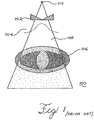
- such systems 100 may include a bow-tie filter 102 to modulate the beam intensity profile 104 across the patient/object 106.
- the bow-tie filter 102 is a block of x-ray attenuation material thicker outside and thinner in the center.
- the filter 102 interacts with the cone-beam of x-rays 108 generated by x-ray source 110 so that the beam intensity profile is modulated so that a less intensive x-ray beam is delivered to the thinner part of the imaged object.
- One disadvantage of such a filter 102 is that the thickness of the imaged object is different for different positions. For example, the thickness of the head of a patient is different from the thickness of the pelvis of the same patient. Also the thickness of the imaged object varies with imaging angles. For example, the pelvis is thinner if imaged in superior-inferior directions than if imaged from lateral directions. Since the intensity profile generated by a bow-tie filter, the current beam intensity modulation using a bow-tie filter does not accommodate different shapes of the imaged object and beam angles.
- US 2006/0008047 discloses a computed tomography device using an x-ray source, comprising a cathode with a plurality of individually programmable electron emitting units together with an anode target that emits x-rays upon impact by the emitted electrons.
- the device includes a collimator which can provide a fan beam geometry and a linear scanning x-ray source is disclosed.
- US 2006/0002506 discloses a volumetric computed tomography system comprising an array of x-ray source positions distributed along a line parallel to an axis of rotation and a plurality of collimators producing thin fan beams.
- US 2003/043957 discloses a volumetric CT scanner having a vane collimator to generate parallel fan beams of x-rays scanning across the object.
- the invention provides a computed tomography system as set out in claim 1, and a method of imaging an object as set out in claim 8.
- Embodiments of the present invention provide the advantage of rejecting scatter without the loss of the signal-to-noise ratio or additional radiation exposure to patient.
- Embodiments of the present invention provide the advantage of modulating beam intensity across a patient to avoid artifacts and to minimize the radiation dose the patient receives.
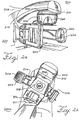
- FIG. 2a shows a wall-mounted scanning slot cone-beam computed tomography system 200 and megavoltage portal imaging system 300 that can be adapted to be used with the cone-beam computed tomography and megavoltage portal imaging system sold under the tradename Synergy by Elekta of Crawley, the United Kingdom.
- the system 200 may be retrofitted onto an existing or new radiation therapy system that includes a separate radiation therapy x-ray source.
- the cone-beam computed tomography system 200 includes an x-ray source, such as x-ray tube 202, a rotary collimator 204 and a flat-panel imager/detector 206 mounted on a gantry 208.
- an x-ray source such as x-ray tube 202
- a rotary collimator 204 and a flat-panel imager/detector 206 mounted on a gantry 208.
- the flat-panel imager 206 can be mounted to the face of a flat, circular, rotatable drum 210 of the gantry 208 of a medical linear accelerator 302, where the x-ray beam 212 produced by the x-ray tube 202 is approximately orthogonal to the treatment beam 304 produced by the radiation therapy source 302.
- a medical linear accelerator 302 where the x-ray beam 212 produced by the x-ray tube 202 is approximately orthogonal to the treatment beam 304 produced by the radiation therapy source 302.
- the system 300 includes a separate radiation therapy x-ray source, such as a linear source 302, and a detector 306 that are separately mounted to the rotating drum 210.
- the source 302 operates at a power level higher than that of x-ray tube 202 so as to allow for treatment of a target volume in a patient lying on movable table 211 (movable in x, y and z-direction via computer 234).
- the linear source 302 generates a beam of x-rays or particles 304, such as photons or electrons, which have an energy ranging from 4 MeV to 25 MeV.
- FIG. 2b Another scanning slot cone-beam computed tomography system 200a and megavoltage portal imaging system 300a is shown in FIG. 2b .
- the system 200a and system 300a can be adapted to be used with the cone-beam computed tomography and megavoltage portal imaging system sold under the tradename Trilogy by Varian Medical Systems of Palo Alto, California.
- the system 200a includes an x-ray tube 202, a rotary collimator 204 and a flat-panel imager/detector 206 similar to those used in the embodiment of FIG. 2a .
- the x-ray tube 202 and collimator 204 are mounted on an arm 214 pivotably mounted to a support 308 of the system 300a.
- the flat panel imager 206 is mounted on an arm 216 mounted to the support 308.
- the x-ray beam 212 produced by the x-ray tube 202 of FIG. 2b is approximately orthogonal to the treatment beam 304 produced by the radiation therapy source 302.
- the system 300 includes a linear source 302 and detector 306 similar to those described previously with respect to FIG. 2a .
- the linear source 302 generates a beam of x-rays or particles 304, such as photons or electrons, which have an energy ranging from 4 MeV to 25 MeV so as to allow for treatment of a target volume in a patient lying on movable table 211 (movable in x, y and z-directions via computer 234).
- the linear source 302 and the detector 306 are connected with support 308.
- FIG. 2c Another scanning slot cone-beam computed tomography system 200c is shown in FIG. 2c .
- the system 200c includes an kilo-voltage x-ray tube 202, a rotary collimator 204 and a flat-panel imager/detector 206 similar to those used in the arrangement of FIG. 2a .
- the x-ray tube 202 and collimator 204 are mounted at one end of a C-arm 218 while the flat panel imager 206 is mounted at the other end of the C-arm 218.
- the C-arm 218 is mounted to a movable base 220 so that it can pivot about axes A and B shown in FIG. 2c .
- the C-arm 218 and base 220 are similar to those of various well known cone-beam computed tomography imaging systems
- the x-ray source 202 of the scanning slot cone-beam computed tomography system 200 of FIG. 2a includes a rotary anode 222 and a stationary cathode 224 enclosed in a glass housing 226, which in turn is positioned within a rotary collimator 204 that includes a plurality of slots 228.
- the rotary collimator 204 can be replaced by a rectangular slot that moves back and forth in a direction parallel to the tangential direction of the collimator 204 in order to reproduce the same scanning action as collimator 204.
- the cathode 224 emits electrons at the anode 222, which is typically made of tungsten or molybdenum. As the electrons strike a single area of space occupied by the anode 222, the tungsten or molybdenum atoms emit X-rays as a beam 230.
- the x-rays can be in the kV energy range.
- the beam 230 emanates towards the rotary collimator 204.
- the slots 228 preferably are spaced equidistantly from one another and each defines a rectangular area have dimensions of 2 by 15 cm, wherein the width of 2 cm is measured along the scanning direction. Of course, other dimensions for the rectangular slot are possible depending on the desired size of the beam.
- the width of beam 230 is greater than the width, d, of each slot 21 as shown in FIGS. 3b and 3d .
- the slot 228 shapes the X-ray conical beam 230 into a fan or slot beam 212 that scans across the detector 206 prior to the components enclosed in the glass housing 226, the collimator 204, and the detector 206 rotating about the patient P via rotation of drum 210.
- the slot 228 intercepts different portions of the beam 230 so that a plurality of fan beams 212 emanate from the slot 228 so as to scan across a width W of the patient. As shown in FIGS.
- the fan beams 212 of X-rays scan or sweep across the patient P from right to left in the transverse plane as indicated by the arrow 232 to create a two-dimensional image at the detector 206.
- the system 200 can be arranged such that the beams 212 scan from left to right.
- the system 200 can be referred to as a scanning slot cone beam computed tomography system.
- the host computer 234 synchronizes the area 236 read from the detector 206 based on the electron beam placement from the cathode 224 (and the generated x-ray beam), the rotation of the collimator 204 and the size of the slots 228 so that the area 236 corresponds to the area the beam 212 would intersect if the patient were absent.
- the detector 206 reads out only the region where the detector is radiated with the primary beam, as indicated by the darkened region 236. Of course, the whole image can be read out and the signal outside the area 236 can be discarded. An imaging signal corresponding to the read out region is sent from detector 206 to computer 234. Any scatter present outside of region 236 is not detected.
- the imaging signals corresponding to the radiation read out for each of the fan beams 212 by the entire detector 206 after a full scan across the width W of the patient by the fan-shaped beams 212 is used by host computer 234 to generate a two-dimensional projection in a manner similar to that described previously with cone beam computed tomography.
- each fan beam 212 has slightly different projection angles, which causes small amount of distortion if they combined into a two dimensional images. It is preferable to use the actual projection angle of each fan beam 212 in cone-beam tomography or tomosynthesis image reconstruction to avoid distortion.
- the detector 206 can be composed of a two-dimensional array of semiconductor sensors that may be each made of amorphous silicon ( ⁇ -Si:H) and thin-film transistors. The analog signal from each sensor is integrated and digitized. The values are transferred to the host computer 234, wherein an image is generated based on the values and shown on display 236.
- the detector 206 can also include a scintillation screen to convert the received x-rays into visible light which is then detected by a two-dimensional array of detectors.
- the computer 234 instructs the drum 210 to rotate causing the x-ray source 202, the collimator 204 and the detector 206 rotate about the patient P to another position so that the scanning process described above can be repeated and another two-dimensional projection is generated.
- the above rotation of the x-ray source 202, collimator 204 and detector 206 is continued until a sufficient number of two-dimensional images are acquired for forming a cone-beam computed tomography image. At most one full rotation should be needed for this purpose (it is envisioned that images formed from a rotation of less than 360° can be formed as well).
- the two-dimensional projections from each position are combined in the computer 234 to generate a three-dimensional image to be shown on display 236 in a manner similar to that of the cone-beam computed tomography systems described previously.
- collimator 208 to be used with systems 200, 200a and 200b is rotary
- a linear moving collimator can be used instead.
- Such a collimator would contain one or more rectangular slots and the collimator would move back and forth along a plane. The combination of the slots and movement of the collimator will produce fan beams that will scan the patient in a manner similar to that described previously.
- the fan beams 212 are not combined by the computer 234 to generate a two-dimensional projection prior to forming the three-dimensional image. Instead, the data read for each fan beam 212 generated at each position of the drum 210 is combined directly to generate the three-dimensional image. Such image generation produces less distortion than that described previously.
- One particular feature of the system 200 is the capability of rejecting scatter without the loss of the signal-to-noise ratio (SNR) or additional radiation exposure to patient. Further, as discussed later, the system 200 can also modulate the beam intensity across the patient to avoid artifacts and to minimize the radiation dose the patient receives.
- SNR signal-to-noise ratio
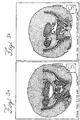
- FIGS. 5 through 7 Various comparisons between the image quality obtained with slot cone beam computed tomography and with conventional cone beam computed tomography are shown in FIGS. 5 through 7 .
- the image quality is significantly better with the slot cone beam computed tomography.
- FIG. 5a shows an image formed from a single cone beam generated from a 15 x 15 cm collimator while FIG. 5b shows an image of the same object generated by the present invention using a beam of a width of 1.5 cm.
- FIG. 6a also shows an image formed from a single cone beam generated from a 15 x 15 cm collimator while FIG. 6b shows an image of the same object generated by the above described arrangement using a beam of a width of 2 cm and length of 15 cm.
- FIG. 5a shows an image formed from a single cone beam generated from a 15 x 15 cm collimator
- FIG. 6b shows an image of the same object generated by the above described arrangement using a beam of a width of 2 cm and length of 15 cm.
- FIG. 7a shows that scatter from a 20 cm diameter phantom using the above described arrangement is less than that generated from a single cone beam interacting with the same phantom as shown in FIG. 7b .
- FIGS. 5-7 show that the images generated by the system 200 are adequate for computer 236 to control the positioning of the radiation source 202 to direct radiation accurately to a desired area of interest of the patient.
- the imaging systems 200, 200a and 200b of FIGS. 2a-c regard the formation of cone-beam tomographic images
- the imaging systems 200, 200a and 200b can be altered to generate digital tomosynthesis images.
- the computer 234 includes software that takes the image data from each of the fan beams and reconstructs them in a well known manner that is different than that of cone-beam computed tomography.
- the use of collimator 204 reduces scatter in the digital tomosynthesis images.
- the fan beams sweeps across the imaged object, its intensity can be dynamically modulated and generate a non-uniformed beam intensity profile similar to that from a physical bow-tie filter.
- the x-ray intensity profile can be modulated based on the shape of the imaged object.
- the x-ray intensity profile can be modulated based on the x-ray projection angle and the shape of the imaged objection.
- One particular feature of the system 200 is the capability of rejecting scatter without the loss of the signal-to-noise ratio (SNR) or additional radiation exposure to patient. Further, as discussed later, the system 10 can also modulate the beam intensity across the patient to avoid artifacts and to minimize the radiation dose the patient receives.
- SNR signal-to-noise ratio
- a rotary collimator see FIGS. 3a-d
- a linearly moving slot collimator can be used to reduce scatter in the cone-beam tomographic images or the digital tomosynthesis images formed by systems 200, 200a and 200b.
- Such collimators can be used to reduce scatter in the megavoltage portal imaging systems 300 and 300a of FIGS. 2a-b .
- Such portal imaging systems preferably direct electrons having energies of about 4MeV to strike a target to produce a x-rays that have energies that range from 0 to 4 MV. The x-rays are used to generate a single image of the object/patient.
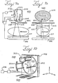
- FIGS. 8a-b An example of a collimator that can be used with systems 300 and 300a is shown in FIGS. 8a-b .
- the dynamic collimator 308 is contained within machine head 310 of the systems 300 and 300a.
- the collimator 308 includes a pair of stationary collimator jaws 312a, b that are made of an x-ray attenuating/absorbing material such as lead.
- the collimator 308 further includes a pair of collimator jaws 314a, b that are made of an x-ray attenuating/absorbing material.
- the jaws 312a, b and 314a, b define a rectangular slot 316. Since the jaws 314a, b move in unison back and forth (see double arrow of FIG. 8b ), the slot 316 is constant in area and moves back and forth (see double arrow of FIG. 8a ) so as to have a fan-shaped beam 304 scan the patient.
- the imager 306, can be a flat panel imager or one or more rows of individual detectors, which are laterally movable via linearly movable arm 318, which intercepts the beam 304 so that an image is formed.
- the detector 306 can be a two dimensional flat panel detector similar imager 206 of systems 200, 200a, 200b. Accordingly, as the slot 316 scans across the field, a plurality of fan beams 304 are directed through the patient onto the imager 206. As with imager 206, any radiation detected outside the area defined by the beam 304 is rejected so that a two-dimensional portal image with minimal scatter is formed.
- the detector 306 is preferably a single or multi-row discrete detector array, wherein each detector has a scintillator and a photodiode.
- the discrete detector can have much better detection efficiency than the previously mentioned flat panel imager. This is due to the thickness of scintillators can be greatly larger than the thickness of scintillation screen. Thus, higher detection efficiency can be achieved.
- the detector array can be a single, linear row of detectors. It is, however, preferable that the row be curved so that all detectors focus onto the megavoltage x-ray source 302.
- the single or multi-row detector array does not cover the whole field-of-view that the slot 316 will scan.
- the detector will move in concert with the slot so that the primary photons of the fan beam 304 are always detected if patient P is not present.
- a precisely controlled linear actuator 318 will be used to move the detector array 306.
- the detector array 306 is preferable to move in the patient's axial direction, either head to toe or toe to head. Of course the detector array 306 can also move left to right or left to right.
- FIGS. 9a-b there is schematically shown a scanning focus spot cone beam computed tomography system 400.
- the system 400 includes an x-ray source 202 with a rotary anode 222 and a fixed cathode 224.
- the cathode 224 may include a metallic filament that generates electrons via thermal emission.
- the rotary anode 222 is made of a material that generates x-rays when struck by electrons, such as tungsten or molybdenum.
- a fixed collimator 402 is positioned either inside or outside the glass housing 226 of the x-ray source 202. While the collimator 402 shown in FIGS. 9a-b contains a single slot 229, it can contain a plurality of slots, wherein each slot is associated with one of the areas of the anode 222 struck by the electrons.
- the focus spot of the electron beam from the cathode 2224 on the anode 222 is moved back and forth, as indicated by the double arrow 404, by deflecting the electron beam with a magnetic or electric field.
- the magnetic or electric field is controlled by a controller or a controller within computer 234.
- the electron beam strikes multiple, discrete areas of space occupied by the anode 222. In the alternative, the electron beam can strike a continuous area.
- the fixed collimator 402 shapes the X-ray beams from the anode 222 into a slot or fan-shaped beam 212, which sweeps across the patient as the focus spot is moved back and forth.
- the cathode 224 emits electrons they are directed to a first area of the surface of the anode 222 from which an initial X-ray beam 230 is generated and is directed at a first direction toward a rectangular slot 228 of the collimator 402.
- a first fan beam 212 is then directed toward a portion of the patient.
- a second fan beam 212 is generated by having the electrons from the cathode 224 directed to a second area of the area of the anode 222. The above process is continued so that a plurality of fan beams 212 are generated that scan across a width W of the patient.
- the fan beams 212 of X-rays scan or sweep across the patient P from right to left in the transverse plane to create a 2-D image at the detector 206 in a manner similar to that described previously with respect to the embodiment of FIGS. 3a-d .
- the system 400 can be arranged such that the beams 212 scan from left to right.
- the two-dimensional detector 206 can be replaced with a one-dimensional detector that moves so as to track the fan beams 212 that scan across the patient P and generates a two-dimensional image in the manner described previously with the embodiment of FIGS. 3a-d .
- the system 400 can be referred to as a scanning focal spot cone beam computed tomography system.
- the x-ray source 202, collimator 402 and detector 206 and variations thereof described above can replace the x-ray source 202, collimator 204 and detector 206 of the computed tomography and digital tomosynthesis systems 200, 200a and 200b of FIGS. 2a-c .
- the generation of images by such systems is performed in a manner similar to that described previously with respect to the embodiment of FIGS. 2-3 .
- FIGS. 2a-c Another approach to improving image quality by reducing scatter is to employ a modified computed tomography system embodying the invention.
- the systems 200, 200a and 200b of FIGS. 2a-c are essentially altered by 1) replacing the x-ray source 202 with a multi-beam x-ray source as will be described below and 2) replacing flat panel imager/detector 206 with a multi-row detector having a curved shape.
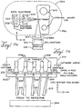
- Such a quasi-cone-beam computed tomography system 500 is schematically shown in FIG. 10 .
- the system 500 includes a linear multi-beam x-ray source 502 and a multi-row discrete scintillator/photodiode detector array 504.
- the array 504 can be constructed from photodiode/scintillator array modules with data acquisition units, which are well known in the art.
- the x-ray source 502 and detector array 504 are mounted on rotating drum 210 so as to be aligned perpendicular to (source 502) and within (array 504) the rotation plane defined by the drum 210.
- the x-ray source 502 includes a single, cylindrical-like glass tube 506 within a vacuum pressure.
- the length of the tube 506 is approximately 38 cm along the z-direction and covers 19 cm in the z-direction at the isocenter.
- a plurality of carbon nanotube cathodes 508, such as 20 in total, are equally spaced from one another by approximately 2 cm.
- each cathode 508 can be replaced by a corresponding metallic filament that is heated to a temperature so that the electrons can be pulled out by establishing a potential between the cathode and the gate electrode 512.
- a potential applied between cathode 508 and an anode 510 produces high local fields, as a result of the small radius of the nano fiber tip and the length of the nano fiber. These high local fields cause electrons to tunnel from the nanotube tip into the vacuum.
- An example of such a nanotube is commercially available from Xintek, Inc., wherein currents as high as 500 mA are available.
- Electrons are pulled out from the carbon nanotube cathode 508 by a potential Vg applied between the gate electrode 512 and the cathode 508.
- the electrons are accelerated by potential V a , and focused into a small focus spot by potential V f and focusing electrodes 514.
- X-ray photons are generated via the bremsstrahlung effect when electrons strike on the molybdenum or tungsten anode target 510 and have an energy of about 80-130keV when imaging a human.
- the focusing electrodes 514 direct the electrons to different portions of the anode target 510 to generate individual x-ray beams in a manner similar to that described with respect to the x-ray source 202 of FIGS. 9a-b .
- conduits 516 are formed within the anode 510 through which cooling water is circulated.
- the tube current i.e., the current of the electrons striking the anode 510 is preferably about 167 mA.
- the x-ray source 502 includes a single anode 510 and a plurality of the cathodes 508 of FIG. 11c , wherein each cathode 508 is controlled by a controller, such as MOSFET controller 518, to activate them in a desired sequence and at a desired current.
- a controller such as MOSFET controller 518
- the cathodes 508 are activated sequentially as described below in order to generate a plurality of x-ray beams that strike discrete areas of space occupied by the anode 510.
- a variable DC voltage, V g ( ⁇ 1 kV) is applied to the gate electrodes to extract the electrons from the cathodes 508.
- a separate controller or computer 234 can be used to control the controller circuit. Electrons are emitted from this activated cathode 508 when V g is larger than the critical field for emission.
- a pulsed controlling signal with pre-determined pulse width is swept across the individual controller 518. At each point, the channel is "opened" to generate an electron beam from the particular cathode 508 which produces an x-ray beam from the corresponding focal point on the anode.
- the cathodes 508 are sequentially switched on and off at a rate of approximately 300 Hz by programming the gate electrode 512, assuming a gantry rotation speed of 60 s/rev, and 600 projections, the tube's z-scanning period is about 0.1 second, 20 cathodes and 50% detector deadtime. Rates of greater than 100 kHz are also possible. As shown in FIG. 11b , the electrons emanating from each cathode 508 strike a different portion of the anode 510 and so a plurality of x-ray beams 230 are formed sequentially at different positions along the z-axis.
- the x-ray beams 230 pass through corresponding filters 520 and a stationary (relative to the x-ray source 801) collimator 522.
- the collimator 522 define slots 524 which correspond to the cathodes 508 in a one-to-one manner.
- the slots 524 can be rectangular in shape with a width less than that of the beams 230 so that fan beams 212 are formed and which are directed to detector 504, as shown in FIGS. 10 and 11b .
- a fan shaped beam sweeps across the patient or object to be imaged.
- the drum 29 slowly rotates around the patient so that a plurality of two-dimensional images are captured that can be used to generate a three-dimensional quasi-cone-beam computed tomography image.
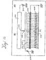
- the x-ray source 502 of FIGS. 10-11 can be replaced with x-ray source 600, schematically shown in FIG. 12 .
- the cathode 602 is continuous line-shaped. Voltages 604 applied to a grid of gate electrodes 602 pull out electrons at different positions. This is controlled by applying gate voltages 604 at different gates. Each electrode's potential 604 can be controlled individually.
- a designed gate voltage profile 606 can be formed to focus the electrons 608 to a focus spot 610 in one dimension. The electrons 608 can be focused in the other dimension by gate 612 and its voltage 614.
- the x-ray beams can scan along the anode 510.
- the major advantage of this embodiment, as compared to the discrete cathode approach in FIGS. 12a-c is that the x-ray beam scanning spatial resolution can be much higher.
- the focus spot 610 can be any position along the anode 510.
- FIG. 13a illustrates the scanning of an x-ray beam 212 across a patient or object at a single position of the x-ray source 502, 600 and detector array 504, wherein the x-ray source 502, 600 is perpendicular to the linear detector array 504.
- the term S n represents each individual focus spot where the electrons strike the anode 510.
- the term D n represents the position of each individual detector of the detector 504.
- the x-ray beam generated at a focus spot is collimated by a corresponding slot 524 into a fan-shaped beam 208.
- a fan-shape beam is indicated in Figure 13a by the triangle area S n -D 100 -D -100 .
- the x-ray beam scans along S 8 -S -8 , it forms a tetrahedral volume.
- the volume scanned at a single position of the x-ray source 502, 600 and detector array 504 is not cone-shaped, which is formed by a point source and a two-dimensional detector in conventional cone-beam computed tomography.
- the new imaging system is quasi cone-beam computed tomography to distinguish it from traditional cone-beam system.
- the curved detector array can be replaced with a linear detector array.
- FIG. 13b shows the volumes scanned at multiple gantry positions by quasi-cone-beam computed tomography, wherein D -100 -D 0 -D 100 are the discrete detectors of detector 504 and S -8 -S 0 -S 8 are the x-ray beams 212 emanating from the slots 524 of collimator 522. As shown in FIG. 12a , D 0 -S -8 -S 8 form a triangular plane. While the drum 210 (or support 308 of FIG. 2b or C-arm 218 of FIG. 2c ) rotates clockwise, the detector D 0 moves to D 0 ', and the x-ray beams move to S -8:8 ', as shown in FIG 13b .
- Another detector occupies exactly the same position as the original position of D 0 .
- a new plane with tilted angle is formed by this detector and source array S -8 '-S 8 '.
- S -8 '-S 8 ' As rotation continues, more and more planes are formed with larger cone angles.
- a cone volume is obtained by stacking these planes together, as shown in FIG. 13c .
- the quasi-cone-beam computed tomography geometry is exactly the same as a conventional cone-beam computed tomography system.
- the same image reconstruction algorithms used for conventional cone-beam computed tomography can be used for image reconstruction for quasi-cone-beam computed tomography.
- An optimum variation of system 500 is to have the individual detector elements of detector 504 focused on the x-ray source 502 so that x-ray cross-talking is minimized and collimators can be used to further reject scatters.
- This configuration also provides easier mounting a collimator grid on the detectors to provide further rejection of in-plane scattering.
- quasi-cone-beam computed tomography is slightly different from cone-beam computed tomography in geometry as shown in FIG. 14a .
- the configuration is the same as in FIG. 13b except that the detectors focus to the x-ray sources.
- the detector on the line S -8:8 -D 0 is not exactly located at the original position of the detector D 0 after the gantry rotates to another angle. It is shifted down slightly. The shifting increases with gantry angle. Thus, the cone, after re-sorting, does not have a unique vertex as shown schematically in FIG. 14b .
- the x-ray beams scan with finite step size, such as 1cm, due to the size of each individual cathode.
- the single-row detector array 504 is replaced by a multi-row linear detector array.
- the detector dimension can be much smaller than the spacing between the cathodes.
- the axial resolution can be increased. Isotropic resolution can be achieved if each individual detector is square-shaped.
- the beam-eye view of the x-ray sources offside the central plane, such as S 8 , the curved detector array is not straight as shown in FIG. 15a .
- the collimator slot openings should be curved for offside x-ray sources as shown in FIG. 15b .
- the collimator 700 has a straight opening in the center and curved openings with gradually increased curvatures offside. The curvature of the slot opening is determined by the curvature of the detector in the beam eye view of the corresponding beam.
- a flat panel detector 206 can be used in a quasi- cone-beam tomography system.
- the scanning x-ray beams 212 from sources 502 or 600 are still collimated to be fan-shaped. Each fan beam is perpendicular to the surface of flat panel detector 206.
- Each fan beam 212 directly irradiates a narrow slit area 236 of detector 206 if no patient P presented. Other areas of the detector 206 receive only scatter and so are not read out as described previously with respect to FIG. 4 . Thus, the majority of scatter is rejected.
- the advantage of this embodiment is the simplicity of obtaining exactly reconstructed images. No complicated scanning loci are necessary.
- An alternative embodiment of the system shown in Fig.16 is to use focused multi-row detector to replace flat panel detector 206. This is the situation in multi-row helical CT scanner. In conventional helical CT scanner, when the number of rows of detectors increases, the cone angle becomes larger. Scatters and approximate reconstruction increase with cone angle. The advantage of this embodiment is that scatters can be largely rejected. Another advantage is the cone angle is small for each x-ray source.
- bow-tie filter 102 has been used in the past to modulate the beam intensity profile across the patient.
- the above described arrangement can avoid the use of a bow-tie filter by modulating the intensity of the fan beams of the systems of FIGS. 2-16 by dynamically controlling the tube current (mA) of each individual fan beam 208 via a controller or via a controller in computer 234. Dynamic mA control can also be combined with a bow-tie filter so that the beam intensity can be modulated two dimensionally.
- the advantage of modulating beam profile with dynamic mA control of each individual fan beam is that the profile can be adjusted easily by programming the tube current.
- the profile can be changed dynamically based of the thickness of body that the beam will pass through. Thickness depends on the shape of the imaged object as well as the gantry angle.
- the thickness of the patient P can be calculated for each individual fan beam 212 ( FIG. 3 ), 230 ( FIG. 9 ), 212 ( FIG. 11 ).
- the optimal tube current mA can be calculated and programmed based on the calculated thickness.
- the beam intensity is controlled in preprogrammed pattern.
- the dynamic mA control includes adjusting the tube current in real-time.
- the signal intensity of one fan beam can be processed.
- the optimal intensity of a second fan beam that immediately follows the one fan beam can be determined by assuming the patient geometry is similar to that of the one fan beam.
- the second fan beam is delivered with a calculated optimal intensity.
- the signal of the second fan beam can be used to determine the intensities of the beams after that. This process is repeated for subsequent fan beams until scanning is finished.
- the delivered intensities of each fan beam need to be recorded for reconstruction.
- the embodiments described above can be implemented in various cone (wide) beam computed tomography systems, including on-board cone-beam computed tomography radiotherapy units, multi-row detector helical computed tomography systems, multi-row detector axial computed tomography systems, and C-arm flat panel cone-beam computed tomography systems, as well as other conventional diagnostic computed tomography systems.
- the applications of the above described quasi-cone-beam computed tomography can be employed in other forms of image guided interventions, such as image-guided surgery/biopsy with C-arm cone-beam computed tomography.
- the scatter rejection mechanism of quasi-cone-beam computed tomography is also applicable to multi-row (as many as 1024 now) helical scanners and digital tomosynthesis.
Claims (13)
- Computertomographiesystem, das aufweist:eine Röntgenstrahlquelle (502), die der Reihe nach mehrere Röntgenstrahlen an verschiedenen Positionen entlang einer Abtastrichtung emittiert;einen Kollimator (522), der so in die mehreren Röntgenstrahlen eingreift, dass von dem Kollimator (522) mehrere fächerförmige Röntgenstrahlen der Reihe nach in Richtung eine Objekts abgestrahlt werden;einen Detektor (504), um die fächerförmigen Röntgenstrahlen zu empfangen, nachdem sie durch das Objekt hindurchgedrungen sind, wobei der Detektor (504) so betrieben werden kann, dass er für jeden der empfangenen fächerförmigen Röntgenstrahlen ein Bildsignal erzeugt;einen Computer, der mit dem Detektor (504) so verbunden ist, dass er die Bildsignale für jeden der empfangenen fächerförmigen Röntgenstrahlen empfängt;eine Einrichtung zum Drehen der Röntgenstrahlquelle (502), des Kollimators (522) und des Detektors (504) um das Objekt, wobei der Computer ausgebildet ist, aus den empfangenen Bildsignalen ein dreidimensionales Computertomographiebild zu erzeugen;und eine Anzeige, die mit dem Computer verbunden ist und das dreidimensionale Computertomographiebild anzeigt;wobei der Detektor (504) eine eindimensionale Anordnung einzelner Detektorelemente aufweist,und wobei der Computer ausgebildet ist, aus den von dem Detektor für jeden der empfangenen fächerförmigen Strahlen erzeugten Bildsignalen mehrere Bildsignale zu rekonstruieren, um daraus das dreidimensionale Computertomographiebild zu erzeugen,dadurch gekennzeichnet, dass
der Kollimator (522) ausgebildet ist, die fächerförmigen Röntgenstrahlen von den verschiedenen Positionen auf die eindimensionale Detektoranordnung (504) zu fokussieren,
wobei jeder der empfangenen fächerförmigen Röntgenstrahlen an dem Detektor (504) mit einem anderen Einstrahlwinkel empfangen wird. - Computertomographiesystem nach Anspruch 1, wobei die Röntgenstrahlquelle eine kV-Röntgenstrahlquelle aufweist.
- Computertomographiesystem nach Anspruch 1, wobei der Kollimator (522) mehrere Schlitze aufweist und wobei jeder der mehreren Schlitze einer der verschiedenen Positionen entspricht.
- Computertomographiesystem nach Anspruch 3, wobei der Kollimator relativ zur Röntgenstrahlquelle stationär ist.
- Computertomographiesystem nach Anspruch 1, wobei die Röntgenstrahlquelle (502) eine Anode (510) und mehrere einzelne Kathoden (508) aufweist, die entlang der Abtastrichtung ausgerichtet sind, wobei jede der mehreren Kathoden (508) Elektronen emittiert, die auf von der Anode (510) eingenommene Raumgebiete auftreffen, die den verschiedenen Positionen entsprechen.
- Computertomographiesystem nach Anspruch 1, wobei die Röntgenstrahlquelle eine Anode (510) und eine einzige entlang der Abtastrichtung ausgerichtete Kathode (602) aufweist, die so ausgebildet ist, dass Elektronen, die von verschiedenen Gebieten der Einzelkathode (602) emittiert werden, auf von der Anode (510) eingenommene Raumgebiete auftreffen, die den verschiedenen Positionen entsprechen.
- Computertomographiesystem nach Anspruch 1, das ferner eine Steuerung aufweist, um die Röntgenstrahlquelle so zu steuern, dass sie die mehreren Röntgenstrahlen der Reihe nach an den verschiedenen Positionen entlang der Abtastrichtung emittiert.
- Verfahren zum Abbilden eines Objekts, wobei das Verfahren aufweist:i) Emittieren mehrerer Röntgenstrahlen aus einer Röntgenstrahlquelle der Reihe nach an verschiedenen Positionen entlang einer Abtastrichtung;ii) Formen mehrerer fächerförmiger Röntgenstrahlen aus den mehreren der Reihe nach aus der Röntgenstrahlquelle emittierten Röntgenstrahlen;iii) Erfassen der fächerförmigen Röntgenstrahlen, die das Objekt durchdrungen haben, mithilfe eines Detektors;iv) Erzeugen von das Objekt betreffenden Bilddaten aus den erfassten fächerförmigen Röntgenstrahlen; undv) Drehen der Röntgenstrahlquelle und der Detektorelemente relativ zu dem Objekt und fortlaufendes Wiederholen der Schritte i) - iv) bis eine das Objekt betreffende Bilddatenmenge erzeugt wurde, die ausreicht, um daraus ein dreidimensionales Computertomographiebild zu erzeugen;Bilden eines dreidimensionalen Computertomographiebildes aus der ausreichenden Bilddatenmenge; und
Anzeigen des dreidimensionalen Computertomographiebildes; Rekonstruieren mehrerer Bildsignale aus den Bilddaten und Erzeugen des dreidimensionalen Computertomographiebildes daraus,
dadurch gekennzeichnet, dass
die fächerförmigen Röntgenstrahlen von den verschiedenen Positionen auf eine gemeinsam genutzte eindimensionale Anordnung von Detektorelementen fokussiert werden,
jeder der erfassten fächerförmigen Röntgenstrahlen an dem Detektor mit einem anderen Einstrahlwinkel erfasst wird. - Verfahren nach Anspruch 8, wobei das dreidimensionale Computertomographiebild höchstens aus einer vollen Umdrehung der Röntgenstrahlquelle und der Detektorelemente um das Objekt gewonnen wird.
- Verfahren nach Anspruch 8, wobei das Emittieren umfasst, dass die Röntgenstrahlen der Reihe nach von verschiedenen Gebieten einer Anode der Röntgenstrahlquelle gebildet werden.
- Verfahren nach Anspruch 10, wobei das Emittieren umfasst, dass die Röntgenstrahlen der Reihe nach von verschiedenen Gebieten der Anode gebildet werden, indem Elektronen von einer Einzelkathode der Röntgenstrahlquelle der Reihe nach in Richtung der verschiedenen Gebiete gerichtet werden.
- Verfahren nach Anspruch 8, wobei die Röntgenstrahlen eine Energie im Kilovoltbereich aufweisen.
- Verfahren nach Anspruch 11, das ferner ein Modulieren der Intensität eines jeden der mehreren fächerförmigen Röntgenstrahlen durch Modulieren des auf die verschiedenen Gebiete der Anode auftreffenden Elektronenstroms umfasst.
Applications Claiming Priority (2)
| Application Number | Priority Date | Filing Date | Title |
|---|---|---|---|
| US79220706P | 2006-04-14 | 2006-04-14 | |
| PCT/US2007/008996 WO2007120744A2 (en) | 2006-04-14 | 2007-04-12 | Scanning slot cone-beam computed tomography and scanning focus spot cone-beam computed tomography |
Publications (3)
| Publication Number | Publication Date |
|---|---|
| EP2010058A2 EP2010058A2 (de) | 2009-01-07 |
| EP2010058A4 EP2010058A4 (de) | 2011-05-18 |
| EP2010058B1 true EP2010058B1 (de) | 2017-05-17 |
Family
ID=38610167
Family Applications (1)
| Application Number | Title | Priority Date | Filing Date |
|---|---|---|---|
| EP07755309.7A Active EP2010058B1 (de) | 2006-04-14 | 2007-04-12 | Computertomographiesystem und -methode |
Country Status (6)
| Country | Link |
|---|---|
| US (2) | US7760849B2 (de) |
| EP (1) | EP2010058B1 (de) |
| JP (2) | JP5538880B2 (de) |
| CN (4) | CN102988073A (de) |
| CA (1) | CA2649320C (de) |
| WO (1) | WO2007120744A2 (de) |
Families Citing this family (163)
| Publication number | Priority date | Publication date | Assignee | Title |
|---|---|---|---|---|
| US10653497B2 (en) | 2006-02-16 | 2020-05-19 | Globus Medical, Inc. | Surgical tool systems and methods |
| US10893912B2 (en) | 2006-02-16 | 2021-01-19 | Globus Medical Inc. | Surgical tool systems and methods |
| US10357184B2 (en) | 2012-06-21 | 2019-07-23 | Globus Medical, Inc. | Surgical tool systems and method |
| US9339243B2 (en) | 2006-04-14 | 2016-05-17 | William Beaumont Hospital | Image guided radiotherapy with dual source and dual detector arrays tetrahedron beam computed tomography |
| CN102988073A (zh) | 2006-04-14 | 2013-03-27 | 威廉博蒙特医院 | 扫描狭槽锥形束计算机断层摄影以及扫描聚焦光斑锥形束计算机断层摄影 |
| US8983024B2 (en) * | 2006-04-14 | 2015-03-17 | William Beaumont Hospital | Tetrahedron beam computed tomography with multiple detectors and/or source arrays |
| CN101489477B (zh) * | 2006-05-25 | 2011-08-03 | 威廉博蒙特医院 | 用于体积图像引导的适应性放射治疗的实时、在线和离线治疗剂量追踪和反馈过程 |
| US8073104B2 (en) * | 2006-05-25 | 2011-12-06 | William Beaumont Hospital | Portal and real time imaging for treatment verification |
| GB2465726A (en) | 2007-08-23 | 2010-06-02 | Fischer Medical Technologies Inc | Improved computed tomography breast imaging and biopsy system |
| US7936858B2 (en) * | 2007-09-28 | 2011-05-03 | Siemens Medical Solutions Usa, Inc. | System and method for tomosynthesis |
| US8144829B2 (en) * | 2008-02-27 | 2012-03-27 | The Board Of Trustees Of The Leland Stanford Junior University | Cone-beam CT imaging scheme |
| JP5398157B2 (ja) * | 2008-03-17 | 2014-01-29 | キヤノン株式会社 | X線撮影装置及びその制御方法 |
| US8532259B2 (en) * | 2008-04-17 | 2013-09-10 | University Of Florida Research Foundation, Inc. | Method and apparatus for computed imaging backscatter radiography |
| US20090285356A1 (en) * | 2008-05-16 | 2009-11-19 | Sirona Dental Systems Gmbh | System and method for patient positioning in cone-beam tomography |
| JP5677301B2 (ja) | 2008-09-10 | 2015-02-25 | アナロジック コーポレーション | 複数ピクセルx線源を使用したコンピュータ断層撮影走査システム及び方法 |
| JP2010075620A (ja) * | 2008-09-29 | 2010-04-08 | Fujifilm Corp | 放射線トモシンセシス撮影装置 |
| EP2250967A1 (de) * | 2009-05-13 | 2010-11-17 | Helmholtz Zentrum München Deutsches Forschungszentrum für Gesundheit und Umwelt (GmbH) | Tomographiegerät und Tomographieverfahren |
| US20110006224A1 (en) * | 2009-07-09 | 2011-01-13 | Maltz Jonathan S | Digital Tomosynthesis in Ion Beam Therapy Systems |
| WO2011033439A1 (en) * | 2009-09-15 | 2011-03-24 | Koninklijke Philips Electronics N.V. | Distributed x-ray source and x-ray imaging system comprising the same |
| US8254518B2 (en) * | 2009-10-05 | 2012-08-28 | Siemens Medical Solutions Usa, Inc. | Acquisition of projection images for tomosynthesis |
| JP2013516278A (ja) | 2010-01-05 | 2013-05-13 | ウィリアム・ボーモント・ホスピタル | 連続治療台回転/移動および同時コーンビーム撮像を用いた強度変調回転放射線治療 |
| WO2011106433A1 (en) | 2010-02-24 | 2011-09-01 | Accuray Incorporated | Gantry image guided radiotherapy system and related treatment delivery methods |
| US8594272B2 (en) | 2010-03-19 | 2013-11-26 | Triple Ring Technologies, Inc. | Inverse geometry volume computed tomography systems |
| DE102010026674B4 (de) | 2010-07-09 | 2012-09-27 | Siemens Aktiengesellschaft | Bildgebungsvorrichtung und Strahlentherapiegerät |
| US9125570B2 (en) * | 2010-07-16 | 2015-09-08 | The Board Of Trustees Of The Leland Stanford Junior University | Real-time tomosynthesis guidance for radiation therapy |
| WO2012021459A1 (en) * | 2010-08-08 | 2012-02-16 | Accuray, Inc. | Radiation treatment delivery system with outwardly movable radiation treatment head extending from ring gantry |
| CN103260523B (zh) * | 2010-12-13 | 2016-02-03 | 飞利浦数字乳房X光照相术瑞典股份公司 | 准直仪装置和方法 |
| US8989469B2 (en) | 2010-12-20 | 2015-03-24 | The Board Of Trustees Of The Leland Stanford Junior University | Systems and methods for simultaneous acquisition of scatter and image projection data in computed tomography |
| US9555264B1 (en) * | 2011-02-15 | 2017-01-31 | Velayudhan Sahadevan | MEMS based parallel microbeam radiosurgery without adaptive resistance to radiation |
| US9237880B2 (en) | 2011-03-17 | 2016-01-19 | Koninklijke Philips N.V. | Composite acoustic backing with high thermal conductivity for ultrasound transducer array |
| WO2012131660A1 (en) | 2011-04-01 | 2012-10-04 | Ecole Polytechnique Federale De Lausanne (Epfl) | Robotic system for spinal and other surgeries |
| DE102011085773B4 (de) * | 2011-11-04 | 2014-08-21 | Siemens Aktiengesellschaft | Dosisrekonstruktion bei der Strahlentherapie |
| EP2816956B1 (de) | 2012-02-22 | 2018-01-17 | Carestream Health, Inc. | Mobile radiografische vorrichtung/verfahren mit tomosynthesekapazität |
| KR101323034B1 (ko) | 2012-04-30 | 2013-11-06 | 재단법인 아산사회복지재단 | 단일 에너지 광자 선원을 이용한 콘빔 ct 촬영 장치 및 이를 이용한 영상 획득 방법 |
| US11298196B2 (en) | 2012-06-21 | 2022-04-12 | Globus Medical Inc. | Surgical robotic automation with tracking markers and controlled tool advancement |
| JP2015528713A (ja) | 2012-06-21 | 2015-10-01 | グローバス メディカル インコーポレイティッド | 手術ロボットプラットフォーム |
| US10624710B2 (en) | 2012-06-21 | 2020-04-21 | Globus Medical, Inc. | System and method for measuring depth of instrumentation |
| US11399900B2 (en) | 2012-06-21 | 2022-08-02 | Globus Medical, Inc. | Robotic systems providing co-registration using natural fiducials and related methods |
| US11395706B2 (en) | 2012-06-21 | 2022-07-26 | Globus Medical Inc. | Surgical robot platform |
| US10874466B2 (en) | 2012-06-21 | 2020-12-29 | Globus Medical, Inc. | System and method for surgical tool insertion using multiaxis force and moment feedback |
| US11864745B2 (en) | 2012-06-21 | 2024-01-09 | Globus Medical, Inc. | Surgical robotic system with retractor |
| US11607149B2 (en) | 2012-06-21 | 2023-03-21 | Globus Medical Inc. | Surgical tool systems and method |
| US11253327B2 (en) | 2012-06-21 | 2022-02-22 | Globus Medical, Inc. | Systems and methods for automatically changing an end-effector on a surgical robot |
| US11317971B2 (en) | 2012-06-21 | 2022-05-03 | Globus Medical, Inc. | Systems and methods related to robotic guidance in surgery |
| US10799298B2 (en) | 2012-06-21 | 2020-10-13 | Globus Medical Inc. | Robotic fluoroscopic navigation |
| US11896446B2 (en) | 2012-06-21 | 2024-02-13 | Globus Medical, Inc | Surgical robotic automation with tracking markers |
| US10842461B2 (en) | 2012-06-21 | 2020-11-24 | Globus Medical, Inc. | Systems and methods of checking registrations for surgical systems |
| US10231791B2 (en) | 2012-06-21 | 2019-03-19 | Globus Medical, Inc. | Infrared signal based position recognition system for use with a robot-assisted surgery |
| US11793570B2 (en) | 2012-06-21 | 2023-10-24 | Globus Medical Inc. | Surgical robotic automation with tracking markers |
| US11786324B2 (en) | 2012-06-21 | 2023-10-17 | Globus Medical, Inc. | Surgical robotic automation with tracking markers |
| US11864839B2 (en) | 2012-06-21 | 2024-01-09 | Globus Medical Inc. | Methods of adjusting a virtual implant and related surgical navigation systems |
| US11589771B2 (en) | 2012-06-21 | 2023-02-28 | Globus Medical Inc. | Method for recording probe movement and determining an extent of matter removed |
| US11857149B2 (en) | 2012-06-21 | 2024-01-02 | Globus Medical, Inc. | Surgical robotic systems with target trajectory deviation monitoring and related methods |
| US10136954B2 (en) | 2012-06-21 | 2018-11-27 | Globus Medical, Inc. | Surgical tool systems and method |
| US11857266B2 (en) | 2012-06-21 | 2024-01-02 | Globus Medical, Inc. | System for a surveillance marker in robotic-assisted surgery |
| US11045267B2 (en) | 2012-06-21 | 2021-06-29 | Globus Medical, Inc. | Surgical robotic automation with tracking markers |
| US10758315B2 (en) | 2012-06-21 | 2020-09-01 | Globus Medical Inc. | Method and system for improving 2D-3D registration convergence |
| US11116576B2 (en) | 2012-06-21 | 2021-09-14 | Globus Medical Inc. | Dynamic reference arrays and methods of use |
| US10646280B2 (en) | 2012-06-21 | 2020-05-12 | Globus Medical, Inc. | System and method for surgical tool insertion using multiaxis force and moment feedback |
| US10350013B2 (en) | 2012-06-21 | 2019-07-16 | Globus Medical, Inc. | Surgical tool systems and methods |
| EP2920791B1 (de) | 2012-11-16 | 2023-12-27 | NeuroLogica Corporation | Drehbarer mehrfachspalt-kollimator |
| US20140169519A1 (en) * | 2012-12-18 | 2014-06-19 | Elekta Ab (Publ) | Cone-beam CT Scanning |
| CN104981205B (zh) * | 2013-01-23 | 2018-09-21 | 卡尔斯特里姆保健公司 | 用于断层融合的定向x射线场 |
| EP2810600B1 (de) * | 2013-06-05 | 2018-08-08 | General Electric Company | Medizinisches Abbildungsverfahren mit variierender Bündelung eines ausgesendeten Strahlenbündels |
| WO2015002276A1 (ja) * | 2013-07-03 | 2015-01-08 | つくばテクノロジー株式会社 | 医療用小型x線撮影装置 |
| KR102139661B1 (ko) | 2013-07-12 | 2020-07-30 | 삼성전자주식회사 | 회전 가능한 시준기를 구비한 ct 시스템 |
| CN103961129B (zh) * | 2013-09-11 | 2016-03-30 | 梁月强 | 旋转光栅锥形束ct |
| US9283048B2 (en) | 2013-10-04 | 2016-03-15 | KB Medical SA | Apparatus and systems for precise guidance of surgical tools |
| US10631800B2 (en) | 2013-11-26 | 2020-04-28 | The Johns Hopkins University | Dual-energy cone-beam computed tomography with a multiple source, single-detector configuration |
| US9241771B2 (en) | 2014-01-15 | 2016-01-26 | KB Medical SA | Notched apparatus for guidance of an insertable instrument along an axis during spinal surgery |
| WO2015121311A1 (en) | 2014-02-11 | 2015-08-20 | KB Medical SA | Sterile handle for controlling a robotic surgical system from a sterile field |
| US9333376B2 (en) * | 2014-03-07 | 2016-05-10 | Pyramid Technical Consultants Inc. | Method and apparatus for calibrating a charged particle pencil beam used for therapeutic purposes |
| EP3134022B1 (de) | 2014-04-24 | 2018-01-10 | KB Medical SA | Halter für ein chirurgisches instrument zur verwendung mit einem chirurgischen robotersystem |
| WO2015168473A1 (en) * | 2014-05-01 | 2015-11-05 | Sigray, Inc. | X-ray interferometric imaging system |
| US10172573B2 (en) * | 2014-05-19 | 2019-01-08 | 3Shape A/S | Radiographic system and method for reducing motion blur and scatter radiation |
| CN103977506B (zh) * | 2014-05-22 | 2016-06-22 | 中国工程物理研究院流体物理研究所 | 一种质子断层扫描方法及装置 |
| WO2015193479A1 (en) | 2014-06-19 | 2015-12-23 | KB Medical SA | Systems and methods for performing minimally invasive surgery |
| EP3169252A1 (de) | 2014-07-14 | 2017-05-24 | KB Medical SA | Rutschfestes chirurgisches instrument zur verwendung bei der herstellung von löchern in knochengewebe |
| US10765438B2 (en) | 2014-07-14 | 2020-09-08 | KB Medical SA | Anti-skid surgical instrument for use in preparing holes in bone tissue |
| WO2016008856A1 (en) * | 2014-07-15 | 2016-01-21 | Koninklijke Philips N.V. | Projection data acquisition apparatus |
| JP6452811B2 (ja) | 2014-10-06 | 2019-01-16 | コーニンクレッカ フィリップス エヌ ヴェKoninklijke Philips N.V. | X線発生装置のための修正構成、修正方法、x線撮像用システム、コンピュータプログラム及びコンピュータ可読媒体 |
| US11103316B2 (en) | 2014-12-02 | 2021-08-31 | Globus Medical Inc. | Robot assisted volume removal during surgery |
| AU2016209275A1 (en) * | 2015-01-21 | 2017-06-29 | California Institute Of Technology | Fourier ptychographic tomography |
| CN104548374B (zh) * | 2015-02-03 | 2017-03-08 | 李宝生 | 基于旋转准直器的cbct图像采集系统及其预处理方法 |
| US10013808B2 (en) | 2015-02-03 | 2018-07-03 | Globus Medical, Inc. | Surgeon head-mounted display apparatuses |
| US10555782B2 (en) | 2015-02-18 | 2020-02-11 | Globus Medical, Inc. | Systems and methods for performing minimally invasive spinal surgery with a robotic surgical system using a percutaneous technique |
| US10278654B2 (en) | 2015-02-25 | 2019-05-07 | J. Morita Manufacturing Corporation | Medical X-ray photographing apparatus and X-ray photographing method |
| JP6050905B2 (ja) * | 2015-02-25 | 2016-12-21 | 株式会社モリタ製作所 | 医療用x線撮影装置及びx線撮影方法 |
| US10058394B2 (en) | 2015-07-31 | 2018-08-28 | Globus Medical, Inc. | Robot arm and methods of use |
| US10646298B2 (en) | 2015-07-31 | 2020-05-12 | Globus Medical, Inc. | Robot arm and methods of use |
| US10080615B2 (en) | 2015-08-12 | 2018-09-25 | Globus Medical, Inc. | Devices and methods for temporary mounting of parts to bone |
| EP3344179B1 (de) | 2015-08-31 | 2021-06-30 | KB Medical SA | Robotische chirurgische systeme |
| US10034716B2 (en) | 2015-09-14 | 2018-07-31 | Globus Medical, Inc. | Surgical robotic systems and methods thereof |
| US9771092B2 (en) | 2015-10-13 | 2017-09-26 | Globus Medical, Inc. | Stabilizer wheel assembly and methods of use |
| US10842453B2 (en) | 2016-02-03 | 2020-11-24 | Globus Medical, Inc. | Portable medical imaging system |
| US10117632B2 (en) | 2016-02-03 | 2018-11-06 | Globus Medical, Inc. | Portable medical imaging system with beam scanning collimator |
| US10448910B2 (en) | 2016-02-03 | 2019-10-22 | Globus Medical, Inc. | Portable medical imaging system |
| US11883217B2 (en) | 2016-02-03 | 2024-01-30 | Globus Medical, Inc. | Portable medical imaging system and method |
| US11058378B2 (en) | 2016-02-03 | 2021-07-13 | Globus Medical, Inc. | Portable medical imaging system |
| US10866119B2 (en) | 2016-03-14 | 2020-12-15 | Globus Medical, Inc. | Metal detector for detecting insertion of a surgical device into a hollow tube |
| DE112017002369T5 (de) | 2016-05-09 | 2019-01-24 | Xinvivo, Inc | Stationäre intraorale Tomosynthesebildgebungssysteme und-Verfahren sowie computerlesbare Medien für die dreidimensionale Dentalbildgebung |
| GB2567115B (en) * | 2016-07-14 | 2022-08-10 | Rapiscan Systems Inc | Systems and methods for improving penetration of radiographic scanners |
| US11039893B2 (en) | 2016-10-21 | 2021-06-22 | Globus Medical, Inc. | Robotic surgical systems |
| US10134155B2 (en) * | 2016-11-21 | 2018-11-20 | Elekta Limited | Systems and methods for real-time imaging |
| JP7233841B2 (ja) | 2017-01-18 | 2023-03-07 | ケービー メディカル エスアー | ロボット外科手術システムのロボットナビゲーション |
| JP2018114280A (ja) | 2017-01-18 | 2018-07-26 | ケービー メディカル エスアー | ロボット外科用システムのための汎用器具ガイド、外科用器具システム、及びそれらの使用方法 |
| EP3351202B1 (de) | 2017-01-18 | 2021-09-08 | KB Medical SA | Universelle instrumentenführung für chirurgische robotersysteme |
| US11071594B2 (en) | 2017-03-16 | 2021-07-27 | KB Medical SA | Robotic navigation of robotic surgical systems |
| US11135015B2 (en) | 2017-07-21 | 2021-10-05 | Globus Medical, Inc. | Robot surgical platform |
| EP3658032A4 (de) * | 2017-07-26 | 2021-03-03 | Shenzhen Xpectvision Technology Co., Ltd. | Röntgenbildgebungssystem und verfahren zur röntgenbildverfolgung |
| JP2020532089A (ja) * | 2017-09-02 | 2020-11-05 | チェッテーン ゲゼルシャフト ミット ベシュレンクテル ハフツング | X線管のための制御デバイス及びx線管を動作させる方法 |
| WO2019090314A1 (en) | 2017-11-06 | 2019-05-09 | The Research Foundation for State University of New York | System and method for dual-use computed tomography for imaging and radiation therapy |
| US11382666B2 (en) | 2017-11-09 | 2022-07-12 | Globus Medical Inc. | Methods providing bend plans for surgical rods and related controllers and computer program products |
| EP3492032B1 (de) | 2017-11-09 | 2023-01-04 | Globus Medical, Inc. | Chirurgische robotische systeme zum biegen von chirurgischen stäben |
| US11794338B2 (en) | 2017-11-09 | 2023-10-24 | Globus Medical Inc. | Robotic rod benders and related mechanical and motor housings |
| US11134862B2 (en) | 2017-11-10 | 2021-10-05 | Globus Medical, Inc. | Methods of selecting surgical implants and related devices |
| EP3527138B1 (de) * | 2018-01-30 | 2022-06-29 | Globus Medical, Inc. | Tragbares medizinisches bildgebungssystem mit strahlabtastung |
| US20190254753A1 (en) | 2018-02-19 | 2019-08-22 | Globus Medical, Inc. | Augmented reality navigation systems for use with robotic surgical systems and methods of their use |
| US10573023B2 (en) | 2018-04-09 | 2020-02-25 | Globus Medical, Inc. | Predictive visualization of medical imaging scanner component movement |
| US11337742B2 (en) | 2018-11-05 | 2022-05-24 | Globus Medical Inc | Compliant orthopedic driver |
| US11278360B2 (en) | 2018-11-16 | 2022-03-22 | Globus Medical, Inc. | End-effectors for surgical robotic systems having sealed optical components |
| US11375970B2 (en) * | 2018-11-30 | 2022-07-05 | Accuray, Inc. | Integrated helical fan-beam computed tomography in image-guided radiation treatment device |
| US11744655B2 (en) | 2018-12-04 | 2023-09-05 | Globus Medical, Inc. | Drill guide fixtures, cranial insertion fixtures, and related methods and robotic systems |
| US11602402B2 (en) | 2018-12-04 | 2023-03-14 | Globus Medical, Inc. | Drill guide fixtures, cranial insertion fixtures, and related methods and robotic systems |
| US11918313B2 (en) | 2019-03-15 | 2024-03-05 | Globus Medical Inc. | Active end effectors for surgical robots |
| US11419616B2 (en) | 2019-03-22 | 2022-08-23 | Globus Medical, Inc. | System for neuronavigation registration and robotic trajectory guidance, robotic surgery, and related methods and devices |
| US11382549B2 (en) | 2019-03-22 | 2022-07-12 | Globus Medical, Inc. | System for neuronavigation registration and robotic trajectory guidance, and related methods and devices |
| US20200297357A1 (en) | 2019-03-22 | 2020-09-24 | Globus Medical, Inc. | System for neuronavigation registration and robotic trajectory guidance, robotic surgery, and related methods and devices |
| US11571265B2 (en) | 2019-03-22 | 2023-02-07 | Globus Medical Inc. | System for neuronavigation registration and robotic trajectory guidance, robotic surgery, and related methods and devices |
| US11317978B2 (en) | 2019-03-22 | 2022-05-03 | Globus Medical, Inc. | System for neuronavigation registration and robotic trajectory guidance, robotic surgery, and related methods and devices |
| US11806084B2 (en) | 2019-03-22 | 2023-11-07 | Globus Medical, Inc. | System for neuronavigation registration and robotic trajectory guidance, and related methods and devices |
| US11045179B2 (en) | 2019-05-20 | 2021-06-29 | Global Medical Inc | Robot-mounted retractor system |
| US11628023B2 (en) | 2019-07-10 | 2023-04-18 | Globus Medical, Inc. | Robotic navigational system for interbody implants |
| JP7022268B2 (ja) * | 2019-08-01 | 2022-02-18 | 恵一 中川 | X線コーンビームct画像再構成方法 |
| US11096642B2 (en) * | 2019-08-16 | 2021-08-24 | GE Precision Healthcare LLC | Methods and systems for X-ray tube conditioning |
| US11571171B2 (en) | 2019-09-24 | 2023-02-07 | Globus Medical, Inc. | Compound curve cable chain |
| US11890066B2 (en) | 2019-09-30 | 2024-02-06 | Globus Medical, Inc | Surgical robot with passive end effector |
| US11426178B2 (en) | 2019-09-27 | 2022-08-30 | Globus Medical Inc. | Systems and methods for navigating a pin guide driver |
| US11864857B2 (en) | 2019-09-27 | 2024-01-09 | Globus Medical, Inc. | Surgical robot with passive end effector |
| US11510684B2 (en) | 2019-10-14 | 2022-11-29 | Globus Medical, Inc. | Rotary motion passive end effector for surgical robots in orthopedic surgeries |
| CN113040797A (zh) * | 2019-12-28 | 2021-06-29 | 上海联影医疗科技股份有限公司 | 一种数字断层成像系统及其摄影方法 |
| US11464581B2 (en) | 2020-01-28 | 2022-10-11 | Globus Medical, Inc. | Pose measurement chaining for extended reality surgical navigation in visible and near infrared spectrums |
| US11382699B2 (en) | 2020-02-10 | 2022-07-12 | Globus Medical Inc. | Extended reality visualization of optical tool tracking volume for computer assisted navigation in surgery |
| US11207150B2 (en) | 2020-02-19 | 2021-12-28 | Globus Medical, Inc. | Displaying a virtual model of a planned instrument attachment to ensure correct selection of physical instrument attachment |
| US11253216B2 (en) | 2020-04-28 | 2022-02-22 | Globus Medical Inc. | Fixtures for fluoroscopic imaging systems and related navigation systems and methods |
| US11153555B1 (en) | 2020-05-08 | 2021-10-19 | Globus Medical Inc. | Extended reality headset camera system for computer assisted navigation in surgery |
| US11382700B2 (en) | 2020-05-08 | 2022-07-12 | Globus Medical Inc. | Extended reality headset tool tracking and control |
| US11510750B2 (en) | 2020-05-08 | 2022-11-29 | Globus Medical, Inc. | Leveraging two-dimensional digital imaging and communication in medicine imagery in three-dimensional extended reality applications |
| US11317973B2 (en) | 2020-06-09 | 2022-05-03 | Globus Medical, Inc. | Camera tracking bar for computer assisted navigation during surgery |
| US11382713B2 (en) | 2020-06-16 | 2022-07-12 | Globus Medical, Inc. | Navigated surgical system with eye to XR headset display calibration |
| EP3933881A1 (de) | 2020-06-30 | 2022-01-05 | VEC Imaging GmbH & Co. KG | Röntgenquelle mit mehreren gittern |
| US11877807B2 (en) | 2020-07-10 | 2024-01-23 | Globus Medical, Inc | Instruments for navigated orthopedic surgeries |
| US11793588B2 (en) | 2020-07-23 | 2023-10-24 | Globus Medical, Inc. | Sterile draping of robotic arms |
| US11737831B2 (en) | 2020-09-02 | 2023-08-29 | Globus Medical Inc. | Surgical object tracking template generation for computer assisted navigation during surgical procedure |
| US11523785B2 (en) | 2020-09-24 | 2022-12-13 | Globus Medical, Inc. | Increased cone beam computed tomography volume length without requiring stitching or longitudinal C-arm movement |
| US11911112B2 (en) | 2020-10-27 | 2024-02-27 | Globus Medical, Inc. | Robotic navigational system |
| US11941814B2 (en) | 2020-11-04 | 2024-03-26 | Globus Medical Inc. | Auto segmentation using 2-D images taken during 3-D imaging spin |
| US11717350B2 (en) | 2020-11-24 | 2023-08-08 | Globus Medical Inc. | Methods for robotic assistance and navigation in spinal surgery and related systems |
| CN112964738B (zh) * | 2021-01-29 | 2022-11-22 | 山东大学 | 一种工业ct快速扫描系统及方法 |
| US11857273B2 (en) | 2021-07-06 | 2024-01-02 | Globus Medical, Inc. | Ultrasonic robotic surgical navigation |
| US11439444B1 (en) | 2021-07-22 | 2022-09-13 | Globus Medical, Inc. | Screw tower and rod reduction tool |
| US11918304B2 (en) | 2021-12-20 | 2024-03-05 | Globus Medical, Inc | Flat panel registration fixture and method of using same |
| WO2023133179A1 (en) * | 2022-01-05 | 2023-07-13 | X-Sight Incorporated | Sub-system x-ray source module |
Family Cites Families (175)
| Publication number | Priority date | Publication date | Assignee | Title |
|---|---|---|---|---|
| US620024A (en) * | 1899-02-21 | Berry-crate | ||
| BE716771A (de) | 1967-06-24 | 1968-12-02 | ||
| GB1283915A (en) * | 1968-08-23 | 1972-08-02 | Emi Ltd | A method of and apparatus for examination of a body by radiation such as x or gamma radiation |
| US3780291A (en) * | 1971-07-07 | 1973-12-18 | American Science & Eng Inc | Radiant energy imaging with scanning pencil beam |
| JPS50153889A (de) * | 1974-05-30 | 1975-12-11 | ||
| JPS5252594A (en) | 1975-10-25 | 1977-04-27 | Shimadzu Corp | Tomographing device |
| JPS5293384A (en) * | 1976-01-31 | 1977-08-05 | Shimadzu Corp | Radiation collimeter for segmental scanning |
| JPS52107793A (en) * | 1976-03-05 | 1977-09-09 | Jeol Ltd | Unit for obtaining x-ray objective axis shift image |
| US4132895A (en) * | 1976-08-28 | 1979-01-02 | Emi Limited | Radiography |
| US4547892A (en) | 1977-04-01 | 1985-10-15 | Technicare Corporation | Cardiac imaging with CT scanner |
| NL7706038A (nl) * | 1977-06-02 | 1978-12-05 | Philips Nv | Aftastende roentgenonderzoekinrichting. |
| US4145613A (en) * | 1977-10-25 | 1979-03-20 | Cgr Medical Corporation | Motorized X-ray tube assembly |
| US4304999A (en) * | 1979-01-02 | 1981-12-08 | Technicare Corporation | Eccentric source collimator assembly for rotating source CT scanner |
| JPS5686400A (en) * | 1979-12-14 | 1981-07-14 | Shimadzu Corp | Collimater for radial tomogram device |
| JPS56101579A (en) | 1980-01-18 | 1981-08-14 | Shimadzu Corp | Radiation type tomography device |
| US4315157A (en) | 1980-05-01 | 1982-02-09 | The University Of Alabama In Birmingham | Multiple beam computed tomography (CT) scanner |
| US4312157A (en) * | 1980-05-19 | 1982-01-26 | Ibg International, Inc. | Greenhouse with hinged roof sections |
| JPS56168578A (en) | 1980-05-30 | 1981-12-24 | Shimadzu Corp | Radiation type tomography apparatus |
| DE3023401A1 (de) * | 1980-06-23 | 1982-01-07 | Siemens AG, 1000 Berlin und 8000 München | Roentgendiagnostikanlage mit einer aufnahmeeinheit mit einer roentgenroehre, die ein faecherfoermiges strahlenbuendel aussendet |
| US4414682A (en) * | 1980-11-17 | 1983-11-08 | American Science And Engineering, Inc. | Penetrating radiant energy imaging system with multiple resolution |
| JPS58163341A (ja) * | 1982-03-24 | 1983-09-28 | 株式会社東芝 | X線診断装置 |
| US4405745A (en) * | 1982-09-24 | 1983-09-20 | Phillips Petroleum Company | Polymer stabilization |
| US4534051A (en) * | 1982-12-27 | 1985-08-06 | John K. Grady | Masked scanning X-ray apparatus |
| DE3532822A1 (de) | 1985-09-13 | 1987-03-26 | Siemens Ag | Stereoroentgenroehre |
| DE3844716C2 (de) * | 1987-08-24 | 2001-02-22 | Mitsubishi Electric Corp | Partikelstrahlmonitorvorrichtung |
| GB2211709B (en) | 1987-10-28 | 1991-03-20 | Philips Electronic Associated | Multileaf collimator and related apparatus |
| NL8800738A (nl) * | 1988-03-24 | 1989-10-16 | Philips Nv | Roentgenonderzoekapparaat met een instelbaar spleetvormig diafragma. |
| SE463187B (sv) | 1989-02-20 | 1990-10-22 | Ao Medical Products Ab | Saett vid och kassetthaallaranordning foer roentgen- eller liknande undersoekning |
| EP0466956A1 (de) * | 1990-07-18 | 1992-01-22 | Siemens Aktiengesellschaft | Computertomograph |
| US5257183A (en) * | 1990-12-21 | 1993-10-26 | General Electric Company | Method and apparatus for converting cone beam X-ray projection data to planar integral and reconstructing a three-dimensional computerized tomography (CT) image of an object |
| JPH04242736A (ja) * | 1991-01-08 | 1992-08-31 | Fuji Photo Film Co Ltd | 放射線画像撮影装置 |
| JPH04307035A (ja) * | 1991-04-05 | 1992-10-29 | Toshiba Corp | X線撮影装置 |
| US5214686A (en) * | 1991-12-13 | 1993-05-25 | Wake Forest University | Three-dimensional panoramic dental radiography method and apparatus which avoids the subject's spine |
| JPH05172764A (ja) | 1991-12-20 | 1993-07-09 | Toshiba Corp | 散乱線画像化装置 |
| DE4202302C2 (de) * | 1992-01-28 | 1999-06-10 | Dietrich H W Prof Groenemeyer | Computer-Tomograph |
| US5351280A (en) * | 1992-03-19 | 1994-09-27 | Wisconsin Alumni Research Foundation | Multi-leaf radiation attenuator for radiation therapy |
| US5661773A (en) | 1992-03-19 | 1997-08-26 | Wisconsin Alumni Research Foundation | Interface for radiation therapy machine |
| US5335255A (en) * | 1992-03-24 | 1994-08-02 | Seppi Edward J | X-ray scanner with a source emitting plurality of fan beams |
| JP2620467B2 (ja) * | 1992-07-16 | 1997-06-11 | 株式会社島津製作所 | X線ct装置 |
| US5966422A (en) | 1992-07-20 | 1999-10-12 | Picker Medical Systems, Ltd. | Multiple source CT scanner |
| JPH06277205A (ja) * | 1993-03-26 | 1994-10-04 | Hamamatsu Photonics Kk | X線診断装置 |
| EP0810006B1 (de) * | 1993-06-09 | 2000-08-30 | Wisconsin Alumni Research Foundation | System zur Strahlungstherapie |
| US5411026A (en) * | 1993-10-08 | 1995-05-02 | Nomos Corporation | Method and apparatus for lesion position verification |
| US5379333A (en) * | 1993-11-19 | 1995-01-03 | General Electric Company | Variable dose application by modulation of x-ray tube current during CT scanning |
| US5848126A (en) | 1993-11-26 | 1998-12-08 | Kabushiki Kaisha Toshiba | Radiation computed tomography apparatus |
| US5521957A (en) * | 1994-03-15 | 1996-05-28 | Hansen; Steven J. | X-ray imaging system |
| JP3168824B2 (ja) * | 1994-04-30 | 2001-05-21 | 株式会社島津製作所 | X線ct装置 |
| US5537452A (en) * | 1994-05-10 | 1996-07-16 | Shepherd; Joseph S. | Radiation therapy and radiation surgery treatment system and methods of use of same |
| DE4421316A1 (de) | 1994-06-17 | 1995-12-21 | Laser Applikationan Gmbh | Vorrichtung zur Positionierung und Markierung eines Patienten an Diagnosegeräten, z.B. vor und nach der Durchleuchtung in einem Computertomographen |
| US5485494A (en) * | 1994-08-03 | 1996-01-16 | General Electric Company | Modulation of X-ray tube current during CT scanning |
| US6345114B1 (en) * | 1995-06-14 | 2002-02-05 | Wisconsin Alumni Research Foundation | Method and apparatus for calibration of radiation therapy equipment and verification of radiation treatment |
| US5754622A (en) * | 1995-07-20 | 1998-05-19 | Siemens Medical Systems, Inc. | System and method for verifying the amount of radiation delivered to an object |
| JP2001509252A (ja) * | 1995-07-31 | 2001-07-10 | リットン システムズ カナダ リミテッド | 電子ノイズの少ない放射線画像形成のためのフラットパネル検出器 |
| GB9520564D0 (en) * | 1995-10-07 | 1995-12-13 | Philips Electronics Nv | Apparatus for treating a patient |
| US5719914A (en) * | 1995-11-13 | 1998-02-17 | Imatron, Inc. | Method for correcting spherical aberration of the electron beam in a scanning electron beam computed tomography system |
| US5657364A (en) * | 1995-12-14 | 1997-08-12 | General Electric Company | Methods and apparatus for detecting beam motion in computed tomography imaging systems |
| US5602892A (en) * | 1996-03-21 | 1997-02-11 | Llacer; Jorge | Method for optimization of radiation therapy planning |
| JPH09262233A (ja) * | 1996-03-28 | 1997-10-07 | Canon Inc | 放射線撮影装置 |
| JP3732568B2 (ja) * | 1996-04-03 | 2006-01-05 | 株式会社東芝 | X線コンピュータ断層撮影装置 |
| US5663995A (en) * | 1996-06-06 | 1997-09-02 | General Electric Company | Systems and methods for reconstructing an image in a CT system performing a cone beam helical scan |
| US5699805A (en) | 1996-06-20 | 1997-12-23 | Mayo Foundation For Medical Education And Research | Longitudinal multiplane ultrasound transducer underfluid catheter system |
| DE19627657C2 (de) | 1996-07-09 | 2003-01-30 | Siemens Ag | Röntgenaufnahmegerät |
| US5949811A (en) | 1996-10-08 | 1999-09-07 | Hitachi Medical Corporation | X-ray apparatus |
| US5877501A (en) * | 1996-11-26 | 1999-03-02 | Picker International, Inc. | Digital panel for x-ray image acquisition |
| JPH10295683A (ja) * | 1997-04-28 | 1998-11-10 | Toshiba Corp | 電子ビームx線ct装置 |
| WO1998052635A1 (en) | 1997-05-23 | 1998-11-26 | William Beaumont Hospital | Method and apparatus for delivering radiation therapy during suspended ventilation |
| JP3664462B2 (ja) | 1997-06-04 | 2005-06-29 | 株式会社東芝 | X線診断装置 |
| US5999587A (en) | 1997-07-03 | 1999-12-07 | University Of Rochester | Method of and system for cone-beam tomography reconstruction |
| WO1999003397A1 (en) | 1997-07-17 | 1999-01-28 | Medlennium Technologies, Inc. | Method and apparatus for radiation and hyperthermia therapy of tumors |
| US6152598A (en) | 1997-09-02 | 2000-11-28 | Kabushiki Kaisha Toshiba | R/F and chest radiography compatible X-ray imaging table |
| US5912943A (en) * | 1997-11-26 | 1999-06-15 | Picker International, Inc. | Cooling system for a sealed housing positioned in a sterile environment |
| US6031888A (en) * | 1997-11-26 | 2000-02-29 | Picker International, Inc. | Fluoro-assist feature for a diagnostic imaging device |
| JP3839941B2 (ja) * | 1997-11-28 | 2006-11-01 | キヤノン株式会社 | 放射線検出装置及び放射線検出方法 |
| EP0958696A2 (de) * | 1997-12-10 | 1999-11-24 | Koninklijke Philips Electronics N.V. | Röntgenuntersuchungsvorrichtung |
| WO1999030616A1 (en) * | 1997-12-16 | 1999-06-24 | Koninklijke Philips Electronics N.V. | Computer tomography device |
| JP3053389B1 (ja) | 1998-12-03 | 2000-06-19 | 三菱電機株式会社 | 動体追跡照射装置 |
| US6041097A (en) * | 1998-04-06 | 2000-03-21 | Picker International, Inc. | Method and apparatus for acquiring volumetric image data using flat panel matrix image receptor |
| US6393096B1 (en) * | 1998-05-27 | 2002-05-21 | Nomos Corporation | Planning method and apparatus for radiation dosimetry |
| AU757570B2 (en) * | 1998-08-06 | 2003-02-27 | Wisconsin Alumni Research Foundation | Method for preparing a radiation therapy plan |
| NZ509667A (en) * | 1998-08-06 | 2003-08-29 | Wisconsin Alumni Res Found | Delivery modification system for radiation therapy |
| JP4354550B2 (ja) * | 1998-08-31 | 2009-10-28 | 株式会社島津製作所 | 放射線治療計画装置 |
| JP2000116631A (ja) | 1998-10-16 | 2000-04-25 | Toshiba Corp | X線診断装置 |
| US6148058A (en) | 1998-10-23 | 2000-11-14 | Analogic Corporation | System and method for real time measurement of detector offset in rotating-patient CT scanner |
| JP2000126164A (ja) | 1998-10-28 | 2000-05-09 | Hitachi Medical Corp | X線装置 |
| US6229870B1 (en) * | 1998-11-25 | 2001-05-08 | Picker International, Inc. | Multiple fan beam computed tomography system |
| US6200024B1 (en) | 1998-11-27 | 2001-03-13 | Picker International, Inc. | Virtual C-arm robotic positioning system for use in radiographic imaging equipment |
| DE19855213C2 (de) * | 1998-11-30 | 2001-03-15 | Siemens Ag | Röntgenaufnahmeeinrichtung |
| JP3402581B2 (ja) * | 1998-11-30 | 2003-05-06 | 日本ビクター株式会社 | データ復元装置 |
| WO2000049840A1 (en) | 1999-02-19 | 2000-08-24 | The Research Foundation Of State University Of New York | Radiographic imaging apparatus and method for vascular interventions |
| US6256370B1 (en) * | 2000-01-24 | 2001-07-03 | General Electric Company | Method and apparatus for performing tomosynthesis |
| JP2000308634A (ja) * | 1999-04-28 | 2000-11-07 | Toshiba Iyo System Engineering Kk | X線ct装置 |
| US6546073B1 (en) * | 1999-11-05 | 2003-04-08 | Georgia Tech Research Corporation | Systems and methods for global optimization of treatment planning for external beam radiation therapy |
| EP3620210A1 (de) * | 2000-02-18 | 2020-03-11 | William Beaumont Hospital | Kegelstrahl-computerisierte tomografie mit einem flachbildschirmbildrechner |
| US6389104B1 (en) * | 2000-06-30 | 2002-05-14 | Siemens Corporate Research, Inc. | Fluoroscopy based 3-D neural navigation based on 3-D angiography reconstruction data |
| US6628745B1 (en) * | 2000-07-01 | 2003-09-30 | Martin Annis | Imaging with digital tomography and a rapidly moving x-ray source |
| US6463122B1 (en) | 2000-08-21 | 2002-10-08 | Bio-Imaging Resource, Inc. | Mammography of computer tomography for imaging and therapy |
| JP2002102217A (ja) * | 2000-09-28 | 2002-04-09 | Ge Medical Systems Global Technology Co Llc | X線ctシステム、ガントリ装置、コンソール端末及びその制御方法及び記憶媒体 |
| US6980627B2 (en) | 2000-10-06 | 2005-12-27 | Xintek, Inc. | Devices and methods for producing multiple x-ray beams from multiple locations |
| US7082182B2 (en) * | 2000-10-06 | 2006-07-25 | The University Of North Carolina At Chapel Hill | Computed tomography system for imaging of human and small animal |
| CN1299634A (zh) * | 2001-01-17 | 2001-06-20 | 上海交通大学 | 基于倒置结构的x射线三维成像扫描方法 |
| JP2002210029A (ja) * | 2001-01-19 | 2002-07-30 | Mitsubishi Electric Corp | 放射線治療装置 |
| FR2820202B1 (fr) * | 2001-01-31 | 2004-06-04 | Snecma Moteurs | Capteur de pression et moteur de fusee l'incorporant |
| CA2410892A1 (en) * | 2001-02-28 | 2002-11-29 | Mitsubishi Heavy Industries, Ltd. | Multi-radiation source x-ray ct apparatus |
| EP1238684B1 (de) | 2001-03-05 | 2004-03-17 | BrainLAB AG | Verfahren zur Erstellung bzw. Aktualisierung eines Bestrahlungsplans |
| US6661870B2 (en) | 2001-03-09 | 2003-12-09 | Tomotherapy Incorporated | Fluence adjustment for improving delivery to voxels without reoptimization |
| US7046831B2 (en) * | 2001-03-09 | 2006-05-16 | Tomotherapy Incorporated | System and method for fusion-aligned reprojection of incomplete data |
| JP3847101B2 (ja) * | 2001-05-22 | 2006-11-15 | ジーイー・メディカル・システムズ・グローバル・テクノロジー・カンパニー・エルエルシー | X線ct装置及び方法 |
| US7145981B2 (en) * | 2001-08-24 | 2006-12-05 | The Board Of Trustees Of The Leland Stanford Junior University | Volumetric computed tomography (VCT) |
| CA2455663C (en) | 2001-08-24 | 2008-02-26 | Mitsubishi Heavy Industries, Ltd. | Radiotherapy apparatus |
| US7072436B2 (en) * | 2001-08-24 | 2006-07-04 | The Board Of Trustees Of The Leland Stanford Junior University | Volumetric computed tomography (VCT) |
| WO2003019610A1 (fr) * | 2001-08-29 | 2003-03-06 | Kabushiki Kaisha Toshiba | Tube a rayons x rotatif a pole positif |
| JP4088058B2 (ja) * | 2001-10-18 | 2008-05-21 | 株式会社東芝 | X線コンピュータ断層撮影装置 |
| JP4282302B2 (ja) * | 2001-10-25 | 2009-06-17 | 株式会社東芝 | X線ct装置 |
| US6888919B2 (en) * | 2001-11-02 | 2005-05-03 | Varian Medical Systems, Inc. | Radiotherapy apparatus equipped with an articulable gantry for positioning an imaging unit |
| US7034309B2 (en) * | 2001-11-13 | 2006-04-25 | Canon Kabushiki Kaisha | Radiation detecting apparatus and method of driving the same |
| US6582121B2 (en) * | 2001-11-15 | 2003-06-24 | Ge Medical Systems Global Technology | X-ray positioner with side-mounted, independently articulated arms |
| US6614877B2 (en) | 2001-11-21 | 2003-09-02 | Ge Medical Systems Global Technology Company Llc | Method and apparatus for enhancing the contrast of a medical diagnostic image acquired using collimation |
| DE10202732A1 (de) * | 2002-01-24 | 2003-08-07 | Fraunhofer Ges Forschung | Vorrichtung und Verfahren zum Erstellen einer Korrekturkennlinie für eine Reduktion von Artefakten bei einer Tomographie |
| US6618466B1 (en) | 2002-02-21 | 2003-09-09 | University Of Rochester | Apparatus and method for x-ray scatter reduction and correction for fan beam CT and cone beam volume CT |
| EP1483022B1 (de) * | 2002-03-12 | 2008-02-13 | Deutsches Krebsforschungszentrum Stiftung des öffentlichen Rechts | Vorrichtung zur durchführung und verifikation einer therapeutischen behandlung sowie zugehöriges computerprogramm |
| US7066930B2 (en) | 2002-04-08 | 2006-06-27 | Cynosure, Inc. | Arrangement for the treatment of barrett's esophagus |
| US6792077B2 (en) | 2002-06-19 | 2004-09-14 | Ge Medical Systems Global Technology Company, Llc | Collimation system for dual slice EBT scanner |
| US20040002641A1 (en) * | 2002-06-24 | 2004-01-01 | Bo Sjogren | Patient representation in medical machines |
| US6865254B2 (en) * | 2002-07-02 | 2005-03-08 | Pencilbeam Technologies Ab | Radiation system with inner and outer gantry parts |
| US7314446B2 (en) * | 2002-07-22 | 2008-01-01 | Ep Medsystems, Inc. | Method and apparatus for time gating of medical images |
| US6760402B2 (en) * | 2002-08-01 | 2004-07-06 | Siemens Medical Solutions Usa, Inc. | Verification of mlc leaf position and of radiation and light field congruence |
| JP4307035B2 (ja) | 2002-09-10 | 2009-08-05 | ホシザキ電機株式会社 | 運搬車 |
| DE10242920B4 (de) * | 2002-09-16 | 2013-08-22 | Siemens Aktiengesellschaft | Verfahren zum Betrieb eines Computertomographiegerätes und eine Vorrichtung zur Durchführung des Verfahrens |
| US7227925B1 (en) * | 2002-10-02 | 2007-06-05 | Varian Medical Systems Technologies, Inc. | Gantry mounted stereoscopic imaging system |
| US7289599B2 (en) * | 2002-10-04 | 2007-10-30 | Varian Medical Systems Technologies, Inc. | Radiation process and apparatus |
| US7657304B2 (en) * | 2002-10-05 | 2010-02-02 | Varian Medical Systems, Inc. | Imaging device for radiation treatment applications |
| US7030386B2 (en) | 2002-10-07 | 2006-04-18 | Sunnybrook And Women's College Health Scinences Centre | High quantum efficiency x-ray detector for portal imaging |
| US7042975B2 (en) * | 2002-10-25 | 2006-05-09 | Koninklijke Philips Electronics N.V. | Four-dimensional helical tomographic scanner |
| US20040122787A1 (en) | 2002-12-18 | 2004-06-24 | Avinash Gopal B. | Enhanced computer-assisted medical data processing system and method |
| US7945021B2 (en) * | 2002-12-18 | 2011-05-17 | Varian Medical Systems, Inc. | Multi-mode cone beam CT radiotherapy simulator and treatment machine with a flat panel imager |
| JP2004236752A (ja) * | 2003-02-04 | 2004-08-26 | Toshiba Medical System Co Ltd | X線コンピュータトモグラフィ装置及びx線撮影装置 |
| WO2004080309A2 (en) | 2003-03-10 | 2004-09-23 | Philips Intellectual Property & Standards Gmbh | Device and method for adapting the recording parameters of a radiograph |
| US20060259282A1 (en) | 2003-03-14 | 2006-11-16 | Failla Gregory A | Deterministic computation of radiation transport for radiotherapy dose calculations and scatter correction for image reconstruction |
| US20040254448A1 (en) | 2003-03-24 | 2004-12-16 | Amies Christopher Jude | Active therapy redefinition |
| DE602004020628D1 (de) * | 2003-07-18 | 2009-05-28 | Koninkl Philips Electronics Nv | Zylindrische röntgenröhre für die computertomographieabbildung |
| JP4535697B2 (ja) * | 2003-07-23 | 2010-09-01 | オリンパス株式会社 | 生体組織の光散乱観測内視鏡装置 |
| US20050027196A1 (en) * | 2003-07-30 | 2005-02-03 | Fitzgerald Loretta A. | System for processing patient radiation treatment data |
| CN1930651B (zh) * | 2003-07-30 | 2010-06-23 | 皇家飞利浦电子股份有限公司 | 整形的阳极x射线管 |
| US6999555B2 (en) * | 2003-09-15 | 2006-02-14 | Varian Medical Systems Imaging Laboratory Gmbh | Systems and methods for processing data |
| CA2540602A1 (en) * | 2003-10-07 | 2005-04-21 | Nomos Corporation | Planning system, method and apparatus for conformal radiation therapy |
| WO2005036147A1 (en) * | 2003-10-14 | 2005-04-21 | Philips Intellectual Property & Standards Gmbh | Fan-beam coherent-scatter computed tomography |
| US7154991B2 (en) * | 2003-10-17 | 2006-12-26 | Accuray, Inc. | Patient positioning assembly for therapeutic radiation system |
| US6980624B2 (en) * | 2003-11-26 | 2005-12-27 | Ge Medical Systems Global Technology Company, Llc | Non-uniform view weighting tomosynthesis method and apparatus |
| US7280631B2 (en) * | 2003-11-26 | 2007-10-09 | General Electric Company | Stationary computed tomography system and method |
| US7394923B2 (en) | 2004-02-10 | 2008-07-01 | The University Of Chicago | Imaging system for generating a substantially exact reconstruction of a region of interest |
| US7907987B2 (en) | 2004-02-20 | 2011-03-15 | University Of Florida Research Foundation, Inc. | System for delivering conformal radiation therapy while simultaneously imaging soft tissue |
| US8160205B2 (en) | 2004-04-06 | 2012-04-17 | Accuray Incorporated | Robotic arm for patient positioning assembly |
| US20050251029A1 (en) | 2004-04-21 | 2005-11-10 | Ali Khamene | Radiation therapy treatment plan |
| US7399977B2 (en) * | 2004-07-23 | 2008-07-15 | University Health Network | Apparatus and method for determining radiation dose |
| WO2006018761A1 (en) | 2004-08-13 | 2006-02-23 | Koninklijke Philips Electronics N.V. | Radiotherapeutic treatment plan adaptation |
| US7062006B1 (en) * | 2005-01-19 | 2006-06-13 | The Board Of Trustees Of The Leland Stanford Junior University | Computed tomography with increased field of view |
| US7193227B2 (en) * | 2005-01-24 | 2007-03-20 | Hitachi, Ltd. | Ion beam therapy system and its couch positioning method |
| US7227923B2 (en) * | 2005-04-18 | 2007-06-05 | General Electric Company | Method and system for CT imaging using a distributed X-ray source and interpolation based reconstruction |
| US8232535B2 (en) | 2005-05-10 | 2012-07-31 | Tomotherapy Incorporated | System and method of treating a patient with radiation therapy |
| US20060269049A1 (en) | 2005-05-26 | 2006-11-30 | Fang-Fang Yin | Dual-detector, simulation CT, and real time function imaging |
| US8077936B2 (en) | 2005-06-02 | 2011-12-13 | Accuray Incorporated | Treatment planning software and corresponding user interface |
| US20070016014A1 (en) * | 2005-06-15 | 2007-01-18 | Kenji Hara | Radio therapy apparatus and operating method of the same |
| WO2006138643A2 (en) | 2005-06-16 | 2006-12-28 | Nomos Corporation | System, tracker, and program product to facilitate and verify proper target alignment for radiation delivery, and related methods |
| US8125813B2 (en) | 2005-06-16 | 2012-02-28 | Best Medical International, Inc. | Variance reduction simulation system, program product, and related methods |
| US7831073B2 (en) * | 2005-06-29 | 2010-11-09 | Accuray Incorporated | Precision registration of X-ray images to cone-beam CT scan for image-guided radiation treatment |
| JP2009502253A (ja) * | 2005-07-22 | 2009-01-29 | トモセラピー・インコーポレーテッド | 関心の移動領域に対して放射線療法を施すシステムおよび方法 |
| JP4386288B2 (ja) * | 2005-08-31 | 2009-12-16 | 株式会社日立製作所 | 放射線治療装置の位置決めシステム及び位置決め方法 |
| US7496181B2 (en) * | 2005-11-28 | 2009-02-24 | The Board Of Trustees Of The Leland Stanford Junior University | X-ray collimator for imaging with multiple sources and detectors |
| CN102988073A (zh) * | 2006-04-14 | 2013-03-27 | 威廉博蒙特医院 | 扫描狭槽锥形束计算机断层摄影以及扫描聚焦光斑锥形束计算机断层摄影 |
| US8073104B2 (en) * | 2006-05-25 | 2011-12-06 | William Beaumont Hospital | Portal and real time imaging for treatment verification |
| US7428292B2 (en) | 2006-11-24 | 2008-09-23 | General Electric Company | Method and system for CT imaging using multi-spot emission sources |
| US7388940B1 (en) * | 2006-11-24 | 2008-06-17 | General Electric Company | Architectures for cardiac CT based on area x-ray sources |
| US8537965B2 (en) * | 2007-04-10 | 2013-09-17 | Arineta Ltd. | Cone-beam CT |
| JP5677301B2 (ja) | 2008-09-10 | 2015-02-25 | アナロジック コーポレーション | 複数ピクセルx線源を使用したコンピュータ断層撮影走査システム及び方法 |
| US8139709B2 (en) * | 2008-09-15 | 2012-03-20 | University Of Utah Research Foundation | Staggered circular scans for CT imaging |
-
2007
- 2007-04-12 CN CN201210348582.3A patent/CN102988073A/zh active Pending
- 2007-04-12 EP EP07755309.7A patent/EP2010058B1/de active Active
- 2007-04-12 CN CN200780022268.3A patent/CN101466313B/zh active Active
- 2007-04-12 CN CN2012103486366A patent/CN102988074A/zh active Pending
- 2007-04-12 US US11/786,781 patent/US7760849B2/en active Active
- 2007-04-12 CA CA2649320A patent/CA2649320C/en active Active
- 2007-04-12 WO PCT/US2007/008996 patent/WO2007120744A2/en active Application Filing
- 2007-04-12 JP JP2009505468A patent/JP5538880B2/ja active Active
- 2007-04-12 CN CN201210348658.2A patent/CN102961159A/zh active Pending
-
2010
- 2010-06-29 US US12/803,480 patent/US8611490B2/en active Active
-
2014
- 2014-04-30 JP JP2014093817A patent/JP6057188B2/ja active Active
Also Published As
| Publication number | Publication date |
|---|---|
| EP2010058A2 (de) | 2009-01-07 |
| CA2649320A1 (en) | 2007-10-25 |
| US20070280408A1 (en) | 2007-12-06 |
| CN101466313B (zh) | 2012-11-14 |
| JP2009533151A (ja) | 2009-09-17 |
| JP5538880B2 (ja) | 2014-07-02 |
| US7760849B2 (en) | 2010-07-20 |
| US8611490B2 (en) | 2013-12-17 |
| CN102988074A (zh) | 2013-03-27 |
| WO2007120744A2 (en) | 2007-10-25 |
| WO2007120744A3 (en) | 2008-06-26 |
| CN102988073A (zh) | 2013-03-27 |
| CA2649320C (en) | 2011-09-20 |
| US20110002439A1 (en) | 2011-01-06 |
| CN101466313A (zh) | 2009-06-24 |
| EP2010058A4 (de) | 2011-05-18 |
| CN102961159A (zh) | 2013-03-13 |
| JP2014133183A (ja) | 2014-07-24 |
| JP6057188B2 (ja) | 2017-01-11 |
Similar Documents
| Publication | Publication Date | Title |
|---|---|---|
| EP2010058B1 (de) | Computertomographiesystem und -methode | |
| US8983024B2 (en) | Tetrahedron beam computed tomography with multiple detectors and/or source arrays | |
| US7751528B2 (en) | Stationary x-ray digital breast tomosynthesis systems and related methods | |
| US9934932B2 (en) | System and method for multi-source X-ray-based imaging | |
| US8180017B2 (en) | Stereo tube attenuation filter | |
| US7580500B2 (en) | Computer tomography system having a ring-shaped stationary X-ray source enclosing a measuring field | |
| EP1959835B1 (de) | Systeme und verfahren zum scannen und zur datenerfassung bei der computer-tomographie (ct) | |
| JP4510754B2 (ja) | X線コンピュータ断層撮影装置 | |
| US9237872B2 (en) | X-ray source with moving anode or cathode | |
| EP2457513B1 (de) | Verfahren und Vorrichtung für die adaptive Exposition in Röntgenstrahlsystemen | |
| JP2020500090A (ja) | コンピュータ断層撮影装置 | |
| WO2022076787A1 (en) | Systems, devices, and methods for multisource volumetric spectral computed tomography | |
| US7184514B2 (en) | X-ray CT apparatus | |
| US20100189211A1 (en) | X-ray souce for measuring radiation | |
| US20230320686A1 (en) | Systems and methods for computed tomography | |
| JP5823178B2 (ja) | X線ct装置 | |
| Cao et al. | Respiratory-gated micro-CT using a carbon nanotube based micro-focus field emission X-ray source |
Legal Events
| Date | Code | Title | Description |
|---|---|---|---|
| PUAI | Public reference made under article 153(3) epc to a published international application that has entered the european phase |
Free format text: ORIGINAL CODE: 0009012 |
|
| 17P | Request for examination filed |
Effective date: 20081112 |
|
| AK | Designated contracting states |
Kind code of ref document: A2 Designated state(s): AT BE BG CH CY CZ DE DK EE ES FI FR GB GR HU IE IS IT LI LT LU LV MC MT NL PL PT RO SE SI SK TR |
|
| AX | Request for extension of the european patent |
Extension state: AL BA HR MK RS |
|
| A4 | Supplementary search report drawn up and despatched |
Effective date: 20110415 |
|
| RIC1 | Information provided on ipc code assigned before grant |
Ipc: A61B 6/03 20060101AFI20081113BHEP Ipc: H01J 35/24 20060101ALI20110411BHEP Ipc: G21K 1/02 20060101ALI20110411BHEP Ipc: H01J 35/30 20060101ALI20110411BHEP Ipc: G21K 1/04 20060101ALI20110411BHEP |
|
| DAX | Request for extension of the european patent (deleted) | ||
| 17Q | First examination report despatched |
Effective date: 20120814 |
|
| RIC1 | Information provided on ipc code assigned before grant |
Ipc: A61B 6/00 20060101ALI20160622BHEP Ipc: G21K 1/02 20060101ALI20160622BHEP Ipc: G21K 1/04 20060101ALI20160622BHEP Ipc: H01J 35/30 20060101ALI20160622BHEP Ipc: H01J 35/24 20060101ALI20160622BHEP Ipc: A61B 6/06 20060101ALI20160622BHEP Ipc: H05G 1/70 20060101ALI20160622BHEP Ipc: A61B 6/02 20060101ALI20160622BHEP Ipc: A61B 6/03 20060101AFI20160622BHEP |
|
| GRAP | Despatch of communication of intention to grant a patent |
Free format text: ORIGINAL CODE: EPIDOSNIGR1 |
|
| GRAJ | Information related to disapproval of communication of intention to grant by the applicant or resumption of examination proceedings by the epo deleted |
Free format text: ORIGINAL CODE: EPIDOSDIGR1 |
|
| GRAP | Despatch of communication of intention to grant a patent |
Free format text: ORIGINAL CODE: EPIDOSNIGR1 |
|
| INTG | Intention to grant announced |
Effective date: 20160802 |
|
| INTG | Intention to grant announced |
Effective date: 20160817 |
|
| GRAJ | Information related to disapproval of communication of intention to grant by the applicant or resumption of examination proceedings by the epo deleted |
Free format text: ORIGINAL CODE: EPIDOSDIGR1 |
|
| GRAP | Despatch of communication of intention to grant a patent |
Free format text: ORIGINAL CODE: EPIDOSNIGR1 |
|
| GRAJ | Information related to disapproval of communication of intention to grant by the applicant or resumption of examination proceedings by the epo deleted |
Free format text: ORIGINAL CODE: EPIDOSDIGR1 |
|
| INTG | Intention to grant announced |
Effective date: 20160927 |
|
| GRAP | Despatch of communication of intention to grant a patent |
Free format text: ORIGINAL CODE: EPIDOSNIGR1 |
|
| INTG | Intention to grant announced |
Effective date: 20161011 |
|
| GRAJ | Information related to disapproval of communication of intention to grant by the applicant or resumption of examination proceedings by the epo deleted |
Free format text: ORIGINAL CODE: EPIDOSDIGR1 |
|
| INTG | Intention to grant announced |
Effective date: 20161018 |
|
| GRAP | Despatch of communication of intention to grant a patent |
Free format text: ORIGINAL CODE: EPIDOSNIGR1 |
|
| INTG | Intention to grant announced |
Effective date: 20161102 |
|
| INTG | Intention to grant announced |
Effective date: 20161123 |
|
| GRAS | Grant fee paid |
Free format text: ORIGINAL CODE: EPIDOSNIGR3 |
|
| GRAA | (expected) grant |
Free format text: ORIGINAL CODE: 0009210 |
|
| AK | Designated contracting states |
Kind code of ref document: B1 Designated state(s): AT BE BG CH CY CZ DE DK EE ES FI FR GB GR HU IE IS IT LI LT LU LV MC MT NL PL PT RO SE SI SK TR |
|
| REG | Reference to a national code |
Ref country code: GB Ref legal event code: FG4D |
|
| REG | Reference to a national code |
Ref country code: CH Ref legal event code: EP |
|
| REG | Reference to a national code |
Ref country code: IE Ref legal event code: FG4D |
|
| REG | Reference to a national code |
Ref country code: AT Ref legal event code: REF Ref document number: 893710 Country of ref document: AT Kind code of ref document: T Effective date: 20170615 |
|
| REG | Reference to a national code |
Ref country code: DE Ref legal event code: R096 Ref document number: 602007051042 Country of ref document: DE |
|
| REG | Reference to a national code |
Ref country code: NL Ref legal event code: MP Effective date: 20170517 |
|
| REG | Reference to a national code |
Ref country code: LT Ref legal event code: MG4D |
|
| REG | Reference to a national code |
Ref country code: AT Ref legal event code: MK05 Ref document number: 893710 Country of ref document: AT Kind code of ref document: T Effective date: 20170517 |
|
| PG25 | Lapsed in a contracting state [announced via postgrant information from national office to epo] |
Ref country code: GR Free format text: LAPSE BECAUSE OF FAILURE TO SUBMIT A TRANSLATION OF THE DESCRIPTION OR TO PAY THE FEE WITHIN THE PRESCRIBED TIME-LIMIT Effective date: 20170818 Ref country code: FI Free format text: LAPSE BECAUSE OF FAILURE TO SUBMIT A TRANSLATION OF THE DESCRIPTION OR TO PAY THE FEE WITHIN THE PRESCRIBED TIME-LIMIT Effective date: 20170517 Ref country code: LT Free format text: LAPSE BECAUSE OF FAILURE TO SUBMIT A TRANSLATION OF THE DESCRIPTION OR TO PAY THE FEE WITHIN THE PRESCRIBED TIME-LIMIT Effective date: 20170517 Ref country code: AT Free format text: LAPSE BECAUSE OF FAILURE TO SUBMIT A TRANSLATION OF THE DESCRIPTION OR TO PAY THE FEE WITHIN THE PRESCRIBED TIME-LIMIT Effective date: 20170517 Ref country code: ES Free format text: LAPSE BECAUSE OF FAILURE TO SUBMIT A TRANSLATION OF THE DESCRIPTION OR TO PAY THE FEE WITHIN THE PRESCRIBED TIME-LIMIT Effective date: 20170517 |
|
| PG25 | Lapsed in a contracting state [announced via postgrant information from national office to epo] |
Ref country code: NL Free format text: LAPSE BECAUSE OF FAILURE TO SUBMIT A TRANSLATION OF THE DESCRIPTION OR TO PAY THE FEE WITHIN THE PRESCRIBED TIME-LIMIT Effective date: 20170517 Ref country code: LV Free format text: LAPSE BECAUSE OF FAILURE TO SUBMIT A TRANSLATION OF THE DESCRIPTION OR TO PAY THE FEE WITHIN THE PRESCRIBED TIME-LIMIT Effective date: 20170517 Ref country code: PL Free format text: LAPSE BECAUSE OF FAILURE TO SUBMIT A TRANSLATION OF THE DESCRIPTION OR TO PAY THE FEE WITHIN THE PRESCRIBED TIME-LIMIT Effective date: 20170517 Ref country code: IS Free format text: LAPSE BECAUSE OF FAILURE TO SUBMIT A TRANSLATION OF THE DESCRIPTION OR TO PAY THE FEE WITHIN THE PRESCRIBED TIME-LIMIT Effective date: 20170917 Ref country code: BG Free format text: LAPSE BECAUSE OF FAILURE TO SUBMIT A TRANSLATION OF THE DESCRIPTION OR TO PAY THE FEE WITHIN THE PRESCRIBED TIME-LIMIT Effective date: 20170817 Ref country code: SE Free format text: LAPSE BECAUSE OF FAILURE TO SUBMIT A TRANSLATION OF THE DESCRIPTION OR TO PAY THE FEE WITHIN THE PRESCRIBED TIME-LIMIT Effective date: 20170517 |
|
| PG25 | Lapsed in a contracting state [announced via postgrant information from national office to epo] |
Ref country code: RO Free format text: LAPSE BECAUSE OF FAILURE TO SUBMIT A TRANSLATION OF THE DESCRIPTION OR TO PAY THE FEE WITHIN THE PRESCRIBED TIME-LIMIT Effective date: 20170517 Ref country code: SK Free format text: LAPSE BECAUSE OF FAILURE TO SUBMIT A TRANSLATION OF THE DESCRIPTION OR TO PAY THE FEE WITHIN THE PRESCRIBED TIME-LIMIT Effective date: 20170517 Ref country code: DK Free format text: LAPSE BECAUSE OF FAILURE TO SUBMIT A TRANSLATION OF THE DESCRIPTION OR TO PAY THE FEE WITHIN THE PRESCRIBED TIME-LIMIT Effective date: 20170517 Ref country code: EE Free format text: LAPSE BECAUSE OF FAILURE TO SUBMIT A TRANSLATION OF THE DESCRIPTION OR TO PAY THE FEE WITHIN THE PRESCRIBED TIME-LIMIT Effective date: 20170517 Ref country code: CZ Free format text: LAPSE BECAUSE OF FAILURE TO SUBMIT A TRANSLATION OF THE DESCRIPTION OR TO PAY THE FEE WITHIN THE PRESCRIBED TIME-LIMIT Effective date: 20170517 |
|
| REG | Reference to a national code |
Ref country code: DE Ref legal event code: R097 Ref document number: 602007051042 Country of ref document: DE |
|
| PG25 | Lapsed in a contracting state [announced via postgrant information from national office to epo] |
Ref country code: IT Free format text: LAPSE BECAUSE OF FAILURE TO SUBMIT A TRANSLATION OF THE DESCRIPTION OR TO PAY THE FEE WITHIN THE PRESCRIBED TIME-LIMIT Effective date: 20170517 |
|
| PLBE | No opposition filed within time limit |
Free format text: ORIGINAL CODE: 0009261 |
|
| STAA | Information on the status of an ep patent application or granted ep patent |
Free format text: STATUS: NO OPPOSITION FILED WITHIN TIME LIMIT |
|
| REG | Reference to a national code |
Ref country code: FR Ref legal event code: PLFP Year of fee payment: 12 |
|
| 26N | No opposition filed |
Effective date: 20180220 |
|
| PG25 | Lapsed in a contracting state [announced via postgrant information from national office to epo] |
Ref country code: SI Free format text: LAPSE BECAUSE OF FAILURE TO SUBMIT A TRANSLATION OF THE DESCRIPTION OR TO PAY THE FEE WITHIN THE PRESCRIBED TIME-LIMIT Effective date: 20170517 |
|
| PG25 | Lapsed in a contracting state [announced via postgrant information from national office to epo] |
Ref country code: MC Free format text: LAPSE BECAUSE OF FAILURE TO SUBMIT A TRANSLATION OF THE DESCRIPTION OR TO PAY THE FEE WITHIN THE PRESCRIBED TIME-LIMIT Effective date: 20170517 |
|
| REG | Reference to a national code |
Ref country code: CH Ref legal event code: PL |
|
| REG | Reference to a national code |
Ref country code: BE Ref legal event code: MM Effective date: 20180430 |
|
| REG | Reference to a national code |
Ref country code: IE Ref legal event code: MM4A |
|
| PG25 | Lapsed in a contracting state [announced via postgrant information from national office to epo] |
Ref country code: LU Free format text: LAPSE BECAUSE OF NON-PAYMENT OF DUE FEES Effective date: 20180412 |
|
| PG25 | Lapsed in a contracting state [announced via postgrant information from national office to epo] |
Ref country code: CH Free format text: LAPSE BECAUSE OF NON-PAYMENT OF DUE FEES Effective date: 20180430 Ref country code: LI Free format text: LAPSE BECAUSE OF NON-PAYMENT OF DUE FEES Effective date: 20180430 Ref country code: BE Free format text: LAPSE BECAUSE OF NON-PAYMENT OF DUE FEES Effective date: 20180430 |
|
| PG25 | Lapsed in a contracting state [announced via postgrant information from national office to epo] |
Ref country code: IE Free format text: LAPSE BECAUSE OF NON-PAYMENT OF DUE FEES Effective date: 20180412 |
|
| PG25 | Lapsed in a contracting state [announced via postgrant information from national office to epo] |
Ref country code: MT Free format text: LAPSE BECAUSE OF NON-PAYMENT OF DUE FEES Effective date: 20180412 |
|
| PG25 | Lapsed in a contracting state [announced via postgrant information from national office to epo] |
Ref country code: TR Free format text: LAPSE BECAUSE OF FAILURE TO SUBMIT A TRANSLATION OF THE DESCRIPTION OR TO PAY THE FEE WITHIN THE PRESCRIBED TIME-LIMIT Effective date: 20170517 |
|
| PG25 | Lapsed in a contracting state [announced via postgrant information from national office to epo] |
Ref country code: PT Free format text: LAPSE BECAUSE OF FAILURE TO SUBMIT A TRANSLATION OF THE DESCRIPTION OR TO PAY THE FEE WITHIN THE PRESCRIBED TIME-LIMIT Effective date: 20170517 Ref country code: HU Free format text: LAPSE BECAUSE OF FAILURE TO SUBMIT A TRANSLATION OF THE DESCRIPTION OR TO PAY THE FEE WITHIN THE PRESCRIBED TIME-LIMIT; INVALID AB INITIO Effective date: 20070412 |
|
| PG25 | Lapsed in a contracting state [announced via postgrant information from national office to epo] |
Ref country code: CY Free format text: LAPSE BECAUSE OF FAILURE TO SUBMIT A TRANSLATION OF THE DESCRIPTION OR TO PAY THE FEE WITHIN THE PRESCRIBED TIME-LIMIT Effective date: 20170517 |
|
| PGFP | Annual fee paid to national office [announced via postgrant information from national office to epo] |
Ref country code: FR Payment date: 20230420 Year of fee payment: 17 Ref country code: DE Payment date: 20230420 Year of fee payment: 17 |
|
| PGFP | Annual fee paid to national office [announced via postgrant information from national office to epo] |
Ref country code: GB Payment date: 20230419 Year of fee payment: 17 |