EP1867497B1 - Run-flat-reifen - Google Patents
Run-flat-reifen Download PDFInfo
- Publication number
- EP1867497B1 EP1867497B1 EP06712643A EP06712643A EP1867497B1 EP 1867497 B1 EP1867497 B1 EP 1867497B1 EP 06712643 A EP06712643 A EP 06712643A EP 06712643 A EP06712643 A EP 06712643A EP 1867497 B1 EP1867497 B1 EP 1867497B1
- Authority
- EP
- European Patent Office
- Prior art keywords
- vehicle
- bead
- rubber
- hardness
- run
- Prior art date
- Legal status (The legal status is an assumption and is not a legal conclusion. Google has not performed a legal analysis and makes no representation as to the accuracy of the status listed.)
- Expired - Fee Related
Links
Images

Classifications
-
- B—PERFORMING OPERATIONS; TRANSPORTING
- B60—VEHICLES IN GENERAL
- B60C—VEHICLE TYRES; TYRE INFLATION; TYRE CHANGING; CONNECTING VALVES TO INFLATABLE ELASTIC BODIES IN GENERAL; DEVICES OR ARRANGEMENTS RELATED TO TYRES
- B60C3/00—Tyres characterised by the transverse section
- B60C3/06—Tyres characterised by the transverse section asymmetric
-
- B—PERFORMING OPERATIONS; TRANSPORTING
- B60—VEHICLES IN GENERAL
- B60C—VEHICLE TYRES; TYRE INFLATION; TYRE CHANGING; CONNECTING VALVES TO INFLATABLE ELASTIC BODIES IN GENERAL; DEVICES OR ARRANGEMENTS RELATED TO TYRES
- B60C11/00—Tyre tread bands; Tread patterns; Anti-skid inserts
- B60C11/0041—Tyre tread bands; Tread patterns; Anti-skid inserts comprising different tread rubber layers
- B60C11/005—Tyre tread bands; Tread patterns; Anti-skid inserts comprising different tread rubber layers with cap and base layers
- B60C11/0058—Tyre tread bands; Tread patterns; Anti-skid inserts comprising different tread rubber layers with cap and base layers with different cap rubber layers in the axial direction
- B60C11/0066—Tyre tread bands; Tread patterns; Anti-skid inserts comprising different tread rubber layers with cap and base layers with different cap rubber layers in the axial direction having an asymmetric arrangement
-
- B—PERFORMING OPERATIONS; TRANSPORTING
- B60—VEHICLES IN GENERAL
- B60C—VEHICLE TYRES; TYRE INFLATION; TYRE CHANGING; CONNECTING VALVES TO INFLATABLE ELASTIC BODIES IN GENERAL; DEVICES OR ARRANGEMENTS RELATED TO TYRES
- B60C11/00—Tyre tread bands; Tread patterns; Anti-skid inserts
- B60C11/03—Tread patterns
- B60C11/0304—Asymmetric patterns
-
- B—PERFORMING OPERATIONS; TRANSPORTING
- B60—VEHICLES IN GENERAL
- B60C—VEHICLE TYRES; TYRE INFLATION; TYRE CHANGING; CONNECTING VALVES TO INFLATABLE ELASTIC BODIES IN GENERAL; DEVICES OR ARRANGEMENTS RELATED TO TYRES
- B60C11/00—Tyre tread bands; Tread patterns; Anti-skid inserts
- B60C11/03—Tread patterns
- B60C11/0327—Tread patterns characterised by special properties of the tread pattern
- B60C11/033—Tread patterns characterised by special properties of the tread pattern by the void or net-to-gross ratios of the patterns
-
- B—PERFORMING OPERATIONS; TRANSPORTING
- B60—VEHICLES IN GENERAL
- B60C—VEHICLE TYRES; TYRE INFLATION; TYRE CHANGING; CONNECTING VALVES TO INFLATABLE ELASTIC BODIES IN GENERAL; DEVICES OR ARRANGEMENTS RELATED TO TYRES
- B60C13/00—Tyre sidewalls; Protecting, decorating, marking, or the like, thereof
- B60C13/009—Tyre sidewalls; Protecting, decorating, marking, or the like, thereof comprising additional bead cores in the sidewall
-
- B—PERFORMING OPERATIONS; TRANSPORTING
- B60—VEHICLES IN GENERAL
- B60C—VEHICLE TYRES; TYRE INFLATION; TYRE CHANGING; CONNECTING VALVES TO INFLATABLE ELASTIC BODIES IN GENERAL; DEVICES OR ARRANGEMENTS RELATED TO TYRES
- B60C15/00—Tyre beads, e.g. ply turn-up or overlap
- B60C15/02—Seating or securing beads on rims
- B60C15/0236—Asymmetric bead seats, e.g. different bead diameter or inclination angle
-
- B—PERFORMING OPERATIONS; TRANSPORTING
- B60—VEHICLES IN GENERAL
- B60C—VEHICLE TYRES; TYRE INFLATION; TYRE CHANGING; CONNECTING VALVES TO INFLATABLE ELASTIC BODIES IN GENERAL; DEVICES OR ARRANGEMENTS RELATED TO TYRES
- B60C17/00—Tyres characterised by means enabling restricted operation in damaged or deflated condition; Accessories therefor
- B60C17/0009—Tyres characterised by means enabling restricted operation in damaged or deflated condition; Accessories therefor comprising sidewall rubber inserts, e.g. crescent shaped inserts
- B60C17/0018—Tyres characterised by means enabling restricted operation in damaged or deflated condition; Accessories therefor comprising sidewall rubber inserts, e.g. crescent shaped inserts two or more inserts in each sidewall portion
-
- B—PERFORMING OPERATIONS; TRANSPORTING
- B60—VEHICLES IN GENERAL
- B60C—VEHICLE TYRES; TYRE INFLATION; TYRE CHANGING; CONNECTING VALVES TO INFLATABLE ELASTIC BODIES IN GENERAL; DEVICES OR ARRANGEMENTS RELATED TO TYRES
- B60C19/00—Tyre parts or constructions not otherwise provided for
- B60C19/001—Tyres requiring an asymmetric or a special mounting
-
- B—PERFORMING OPERATIONS; TRANSPORTING
- B60—VEHICLES IN GENERAL
- B60C—VEHICLE TYRES; TYRE INFLATION; TYRE CHANGING; CONNECTING VALVES TO INFLATABLE ELASTIC BODIES IN GENERAL; DEVICES OR ARRANGEMENTS RELATED TO TYRES
- B60C1/00—Tyres characterised by the chemical composition or the physical arrangement or mixture of the composition
- B60C2001/0033—Compositions of the sidewall inserts, e.g. for runflat
-
- Y—GENERAL TAGGING OF NEW TECHNOLOGICAL DEVELOPMENTS; GENERAL TAGGING OF CROSS-SECTIONAL TECHNOLOGIES SPANNING OVER SEVERAL SECTIONS OF THE IPC; TECHNICAL SUBJECTS COVERED BY FORMER USPC CROSS-REFERENCE ART COLLECTIONS [XRACs] AND DIGESTS
- Y02—TECHNOLOGIES OR APPLICATIONS FOR MITIGATION OR ADAPTATION AGAINST CLIMATE CHANGE
- Y02T—CLIMATE CHANGE MITIGATION TECHNOLOGIES RELATED TO TRANSPORTATION
- Y02T10/00—Road transport of goods or passengers
- Y02T10/80—Technologies aiming to reduce greenhouse gasses emissions common to all road transportation technologies
- Y02T10/86—Optimisation of rolling resistance, e.g. weight reduction
-
- Y—GENERAL TAGGING OF NEW TECHNOLOGICAL DEVELOPMENTS; GENERAL TAGGING OF CROSS-SECTIONAL TECHNOLOGIES SPANNING OVER SEVERAL SECTIONS OF THE IPC; TECHNICAL SUBJECTS COVERED BY FORMER USPC CROSS-REFERENCE ART COLLECTIONS [XRACs] AND DIGESTS
- Y10—TECHNICAL SUBJECTS COVERED BY FORMER USPC
- Y10T—TECHNICAL SUBJECTS COVERED BY FORMER US CLASSIFICATION
- Y10T152/00—Resilient tires and wheels
- Y10T152/10—Tires, resilient
- Y10T152/10495—Pneumatic tire or inner tube
- Y10T152/10819—Characterized by the structure of the bead portion of the tire
-
- Y—GENERAL TAGGING OF NEW TECHNOLOGICAL DEVELOPMENTS; GENERAL TAGGING OF CROSS-SECTIONAL TECHNOLOGIES SPANNING OVER SEVERAL SECTIONS OF THE IPC; TECHNICAL SUBJECTS COVERED BY FORMER USPC CROSS-REFERENCE ART COLLECTIONS [XRACs] AND DIGESTS
- Y10—TECHNICAL SUBJECTS COVERED BY FORMER USPC
- Y10T—TECHNICAL SUBJECTS COVERED BY FORMER US CLASSIFICATION
- Y10T152/00—Resilient tires and wheels
- Y10T152/10—Tires, resilient
- Y10T152/10495—Pneumatic tire or inner tube
- Y10T152/10855—Characterized by the carcass, carcass material, or physical arrangement of the carcass materials
- Y10T152/10864—Sidewall stiffening or reinforcing means other than main carcass plies or foldups thereof about beads
Definitions
- the present invention relates to a so-called side reinforcing type run-flat tire provided with a reinforcing rubber layer arranged at a sidewall portion.
- the reinforcing rubber layer supports a tire so as to suppress a flattening at a time when an air pressure in an inner portion of the tire is lowered due to a puncture or the like, whereby a run-flat traveling can be executed.
- Patent Documents 1 and 2 there is disclosed a so-called double bead type run-flat tire provided with a first bead arranged in an outer circumferential side of a rim base, and a second bead arranged in an annular bulging portion extending to an outer side in a tire width direction of a bead portion.
- the annular inflating portion reinforced by the second bead is pressed to an outer circumferential curved side face of a rim flange at a time of a run-flat traveling, a fitting force to the rim is increased, and it is possible to improve a rim unseating resistance.
- the second bead also exists in an inner side of the vehicle, however, the second bead in the inner side of the vehicle has a small effect to the bead unseating, and an increase of a tire mass, an increase of a rolling resistance and a reduction of a riding comfortableness are caused by employing the symmetrical double bead structure, additionally.
- the double bead structure is employed in the outer side of the vehicle, and the double bead structure is not employed in the inner side of the vehicle, a difference of deflection amount in the side portions in both sides becomes extremely large at a time of the run-flat. Accordingly, since an asymmetry characteristic of a ground contact pressure distribution of a tread surface becomes extremely large, and there is generated a partial-abrasion and a problem that a drivability is lowered, there has been no example in which the double bead structure is employed only in the outer side of the vehicle.
- Patent Document 3 discloses a pneumatic tire in which a groove area in an outer side of a vehicle than an equator line of a tread is smaller than a groove area in an inner side of the vehicle (a void rate is smaller), and a rubber hardness in the outer side of the vehicle is larger than a rubber hardness in the inner side of the vehicle, however, does not teach a solving means in a technique in which the double bead structure is employed only in the outer side of the vehicle.
- an object of the present invention is to provide a run-flat tire which can achieve a reduction of a tire mass, a reduction of a rolling resistance and an improvement of a riding comfortableness, while maintaining a bead unseating performance and a partial-abrasion resistant performance.
- a run-flat tire comprising:
- the present invention it is possible to effectively prevent the bead unseating with respect to a lateral force generated at the outside of the vehicle at a time when the vehicle turns, which most tends to cause the bead unseating in the run-flat traveling state, on the basis of the double bead structure employed at the outside of the vehicle. Further, since it is possible to effectively prevent the bead unseating in the double bead structure, it is possible to make the rubber hardness small or make the thickness small in the reinforcing rubber layer at the outside of the vehicle than the reinforcing rubber layer at the inside of the vehicle at a time of balancing the deflection amount in both sides.
- a tread pattern formed in the tread portion is preferably structured such that a void rate at the outside of the vehicle is equal to or less than a void rate at the inside of the vehicle on the boundary of a tire equator line.
- the void rate means a value obtained by dividing the groove area in each of the regions by a whole area and expressing by a percentage. If the void rate at the outside of the vehicle is equal to or less than the void rate at the inside of the vehicle, the tread center portion generates a buckling in an internal pressure reduced state, and a pattern shear rigidity at the outside of the vehicle having the small void rate becomes larger when the vehicle turns even in the case that a ground contact pressure of the shoulder portion is increased. Accordingly, since a cornering power is increased, it is possible to reduce a slip angle of the tire, and since a moment in the bead unseating direction applied to the tire becomes smaller, it is possible to more effectively prevent the bead unseating.
- the tread portion is preferably structured such that at least a cap rubber has a rubber boundary line having a different hardness at a position which is 40 to 60% of the tread width, and the rubber hardness in the outer side of the vehicle of the boundary line is equal to or more than the rubber hardness in the inner side of the vehicle.
- the tread width indicates a width of shoulder points in both sides at which an imaginary line extended to the shoulder side at a radius of curvature of the tread surface of the tread pattern intersects two imaginary lines extended to the shoulder side at a radius of curvature of buttresses in both sides, in the tire cross section.
- the tread center portion since the rubber hardness in the outer side of the vehicle is equal to or more than the rubber hardness in the inner side of the vehicle, the tread center portion generates the buckling in the internal pressure reduced state. Further, since the pattern shear rigidity at the outside of the vehicle having the small void rate becomes larger at a time when the vehicle turns, even in the case that the ground contact pressure of the shoulder portion is increased, the cornering power is increased, so that it is possible to reduce the slip angle of the tire. Further, since the moment in the bead unseating direction applied to the tire becomes smaller, it is possible to more effectively prevent the bead unseating.
- Fig. 1 is a tire meridian cross sectional view showing an example of a run-flat tire in accordance with the present invention at a time of being installed to a regular rim.
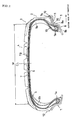
- Fig. 2 is an expansion plan view showing an example of a tread pattern of the run-flat tire shown in Fig. 1 .
- the run-flat tire in accordance with the present invention is provided with a pair of bead portions 1, sidewall portions 2 respectively extending to an outer side in a tire diameter direction from the bead portions 1, and a tread portion 4 connecting the respective outer peripheral side ends of the sidewall portions 2 to each other via shoulder portions 3, as shown in Fig. 1 .
- a bead 1a (corresponding to the first bead) in which a converged body of bead wires, for example, constituted by a steel wire is formed in an annular shape in a tire circumferential direction, and a bead filler 15.
- the tire is firmly fitted and attached onto a rim 8 in a state in which a portion between the bead portions 1 is reinforced by a carcass layer 5, by winding back an end portion of the carcass layer 5 by the bead 1a so as to lock.
- the bead portion 1 is arranged in the tire outer circumferential side of a rim base 8b of the rim 8, and is pressed to the rim flange 8a on the basis of an air pressure in the inner portion of the tire.
- An inner liner layer 6 for maintaining the air pressure is arranged in an inner circumferential side of the carcass layer 5.
- a belt layer 7 for reinforcing on the basis of a hoop effect is arranged in an outer circumferential side of the carcass layer 5, and a tread pattern is formed by a tread rubber on an outer circumferential surface of the belt layer 7.
- a constructing material of the carcass layer 5 and the belt layer 7 it is possible to use a steel, an organic fiber such as a polyester, a rayon, a nylon, aramid and the like. These materials are normally applied a surface treatment, an adhesion treatment or the like for increasing an adhesive property with the rubber.
- a reinforcing rubber layer 9 in which a tire meridian cross section is formed approximately in a crescent shape is arranged in an inner side of the carcass layer 5 of the sidewall portion 2. Accordingly, when an air pressure in the inner portion of the tire is lowered, a flattening of the tire is suppressed, and a run-flat traveling can be executed.
- a raw material rubber of the rubber layer or the like mentioned above there can be listed up a natural rubber, a styrene butadiene rubber (SBR), a butadiene rubber (BR), an isoprene rubber (IR), a butyl rubber (IIR) and the like, and these materials are used independently by one kind, or by being mixed two or more kinds. Further, these rubbers are reinforced by a filler such as a carbon black, a silica or the like, and are appropriately blended with a vulcanizing agent, a vulcanization accelerator, a plasticizing material, an age resistor or the like.
- SBR styrene butadiene rubber
- BR butadiene rubber
- IR isoprene rubber
- IIR butyl rubber
- a double bead structure is employed only at the outside of the vehicle at a time of being installed to the tire.
- the structure is provided with an annular bulging portion 10 provided on the outside in the tire width direction of the bead portion 1 arranged at the outside of the vehicle, and having an inner circumferential side face 11 opposing to an outer circumferential curved side face of the rim flange 8a when the regular rim is fixed, and an annular second bead 1b arranged at the annular bulging portion 10.
- the inner circumferential side face 11 of the annular bulging portion 10 is brought into contact with the outer circumferential curved side face of the rim flange 8a, a diameter reduced portion holding a leading end of the rim flange 8a exists, and the second bead 1b is provided in the tire outer circumferential side of the diameter reduced portion.
- the annular bulging portion 10 is smoothly connected to the sidewall portion 2 in a state in which the portion provided with the second bead 1b is set to an approximately top portion.
- the annular bulging portion 10 is not limited to the shape shown in the present embodiment, but may be structured, for example, such that the tire meridian cross section is formed in a semicircular shape, a trapezoidal shape or the like.
- a hardness of the rubber mainly constituting the annular bulging portion 10 is preferably set to 66 to 76 degree for maintaining a bead unseating resistance and a rim displacement resistance and improving a riding comfortableness while taking into consideration the matter that the rubber hardness of the reinforcing rubber layer 9a at the outside of the vehicle is made small.
- the bead 1b (corresponding to the second bead) in which the bead wire is formed in an annular shape in the tire circumferential direction is arranged in the annular bulging portion 10.
- the bead 1b in accordance with the present embodiment is arranged in such a manner that a center position is positioned in a tire outer circumferential side from an outermost diameter point of the rim flange 8a and in an outer side in the tire width direction, at a time of being installed to the rim.
- the bead wire constituting the bead 1b is not limited to the structure constituted by the converged body of the same steel wires as those of the bead 1a, but may be constituted, for example, by a converged body of organic fibers or a rubber bead made of a fiber reinforcing rubber.
- a rim protector 12 protecting the rim flange 8a when the regular rim is fixed is provided in the outer side in the tire width direction of the bead portion 1 arranged at the inside of the vehicle, however, the structure may be made such as to form a shape smoothly connected to the sidewall portion 2 from a disconnected position from the rim flange 8a without setting the rim protector 12.
- the reinforcing rubber layer 9a arranged at the outside of the vehicle has a rubber hardness of 60 and 82 degree, and preferably has a rubber hardness of 65 and 78 degree. If the rubber hardness is less than 60 degree, a run-flat durability and a bead unseating performance become insufficient, and if the rubber hardness gets over 82 degree, it is impossible to balance with a deflecting amount of the inner side of the vehicle at a time of the run-flat, a partial-abrasion tends to be generated, and it is impossible to achieve an improvement of the riding comfortableness.
- the reinforcing rubber layer 9b arranged at the inside of the vehicle has a rubber hardness of 65 and 90 degree, and preferably has a rubber hardness of 70 and 85 degree. If the rubber hardness is less than 65 degree, it is impossible to balance with the deflecting amount of the inside of the vehicle at a time of the run-flat, and the partial-abrasion tends to be generated, and if the rubber hardness gets over 90 degree, the reduction of the ride comfortableness tends to be generated.
- the reinforcing rubber layer 9b arranged at the inside of the vehicle has the rubber hardness equal to or more than the rubber hardness of the reinforcing rubber layer 9a arranged at the outside of the vehicle, and the reinforcing rubber layer 9b preferably has the rubber hardness which is larger than the rubber hardness of the reinforcing rubber layer 9a by at least 5 degree.
- the reinforcing rubber layer 9b arranged at the inside of the vehicle has a maximum thickness which is larger than that of the reinforcing rubber layer 9a arranged at the outside of the vehicle by at least 0.5 mm, and preferably has a maximum thickness which is larger than that of the reinforcing rubber layer 9a by 0.8 to 1.5 mm.
- the maximum thickness of the reinforcing rubber layer 9a arranged in the outer side of the vehicle is between 9 and 12 mm
- the maximum thickness of the reinforcing rubber layer 9b arranged at the inside of the vehicle is between 9.8 and 13.5 mm.
- the reinforcing rubber layers 9a and 9b are not limited to be constituted by the single rubber layer, but may be structured by a plurality of rubber layers having different physical properties such as a hardness or the like. In this case, it is sufficient that an average value of the rubber layers in the respective layers is within the range mentioned above.
- the reinforcing rubber layer 9a arranged at the outside of the vehicle is formed by a single rubber layer
- the reinforcing rubber layer 9b arranged at the inside of the vehicle is formed by two rubber layers
- the carcass layer 5 exists between both layers.
- the carcass layer 5 is constructed by two layers
- the reinforcing rubber layer 9b is arranged in an inside of each of the carcass layers 5 positioned in the sidewall portion 2.
- the reinforcing rubber layer 9a is arranged in an inside of two carcass layers 5 positioned in the sidewall portion 2
- a reinforcing layer 16 may be arranged approximately along an inner circumferential face of the annular bulging portion 10, whereby it is possible to reinforce an inner circumferential face of the annular bulging portion 10 so as to suppress an attrition.
- the reinforcing layer 16 there can be exemplified a chafer constructed by a steel cord, or an organic fiber such as a rayon, a nylon, a polyester, an aramid or the like.
- the tread portion 4 in the present invention has a tread pattern, for example, as shown in Fig. 2 .
- the tread pattern formed in the tread portion 4 is structured such that a void rate of a vehicle outer side region A1 is equal to or less than a void rate of a vehicle inner side region A2 on the boundary of a tire equator line CL. It is more preferable that the void rate of the vehicle outer side region A1 is 75 to 93% of the void rate of the vehicle inner side region A2. If this value is too small, there is a tendency that a partial-abrasion inside of the vehicle is enlarged.
- the void rate of the vehicle outer side region A1 is between 25 and 35%, and the void rate of the vehicle inner side region A2 is between 30 and 40%.
- the tread portion 4 has a boundary line TB of the rubbers having different hardness at a position A3 at which at least a cap rubber is 40 to 60% of a tread width W, and the rubber hardness in an outer side of the vehicle in the boundary line TB is equal to or more than the rubber hardness in an inner side of the vehicle. It is more preferable that the rubber hardness in the outer side of the vehicle in the boundary line TB is 105 to 117% of the rubber hardness in the inner side of the vehicle. If this value is too large, there is a tendency that the partial-abrasion at the inside of the vehicle is enlarged.
- the rubber hardness in the outer side of the vehicle in the boundary line TB is between 62 and 70 degree, and the rubber hardness in the inner side of the vehicle is between 57 and 65 degree.
- the boundary line TB of the rubbers having the different hardness is arranged in the groove bottom.
- evaluation items in the embodiment are measured as follows.
- a measurement is carried out under a condition that an internal pressure is 0 kPa, and a load is 50% of a total wheel weight in a so-called flat belt type cornering tester.
- a cornering power is evaluated by an index number in a state of setting the cornering power in a comparative example 1 to 100. The larger the index number is, the larger the cornering power is. Accordingly, this structure is preferable.
- test tire is installed to a left front side of an actual car (Japanese 3000 cc class FR vehicle), and the car turns clockwise on a circular course having a radius of 20 m from a straight running state.
- Each of the test tires is set to a run-flat state having the internal pressure of 0 kPa, and the bead unseating resistance is evaluated on the basis of the running speed (which is in proportion to a side G) at a time when the rim unseating is generated.
- the running speed is started from 25 km/h, and the traveling is executed until the rim unseating is generated, in increments of 5 km/h.
- the evaluation is carried out on the basis of the index number by setting the comparative example 1 to 100, and the larger numerical value indicates the fact that the running speed at a time when the rim unseating is generated is high, that is, the bead unseating resistance is excellent.
- the mass is evaluated on the basis of a product tire weight.
- the evaluation is carried out on the basis of the index number by setting the comparative example 1 to 100, and the larger the numerical value indicates the fact that the tire weight is larger.
- the rolling resistance is measured in a uniaxial type rolling resistance tester by assembling the trial tire in a rim having a size 18x8-JJ, and after charging an internal pressure 230 kPa.
- the rolling resistance is evaluated on the basis of an index number by setting the rolling resistance in the comparative example 1 to 100. The smaller the index number is, the smaller and more preferable the rolling resistance is.
- the partial-abrasion is compared on the basis of a ratio of abrasion amount between a center main groove and a shoulder main groove by installing the tire to the actual car (Japanese 3000 cc class FR car) and running on an open road at 12000 km.
- the ratio (between the shoulder main groove abrasion amount and the center main groove abrasion amount) being close to 1.0 indicates a uniform abrasion.
- the steering stability is compared on the basis of a subjective evaluation by the actual car (Japanese 3000 cc class FR car).
- the steering stability is evaluated on the basis of an index number by setting the steering stability in the comparative example 1 to 100. The larger the index number is, the higher and more preferable the steering stability is.
- the riding comfortableness is compared on the basis of a subjective evaluation by the actual car (Japanese 3000 class FR car).
- the riding comfortableness is evaluated on the basis of an index number by setting the riding comfortableness in the comparative example 1 to 100. The larger the index number is, the better and more preferable the riding comfortableness is.
- test tires having a structure shown in Fig. 1 , having a rubber hardness of a vehicle outer side reinforcing rubber layer, a rubber hardness of a vehicle inner side reinforcing rubber layer, a difference of maximum thickness between both side reinforcing rubber layers, void rate in an outer side of a vehicle/void rate in an inner side of the vehicle, and rubber hardness in the outer side of the vehicle/rubber hardness in the inner side of the vehicle shown in Table 1, and having a size 245/40R18.
- a boundary of the rubber of the tread in the embodiment 5 is set to a position which is 50% of the tread width from the outer side of the vehicle.
- Table 1 The result of evaluation is shown in Table 1 in addition.
- test tire having a double bead structure in both the outer side of the vehicle and the inner side of the vehicle, having a rubber hardness of a vehicle outer side reinforcing rubber layer, a rubber hardness of a vehicle inner side reinforcing rubber layer, a difference of maximum thickness between both side reinforcing rubber layers, void rate in an outer side of a vehicle/void rate in an inner side of the vehicle, and rubber hardness in the outer side of the vehicle/rubber hardness in the inner side of the vehicle shown in Table 1, and having a size 245/40R18.
- the result of evaluation is shown in Table 1 in addition.
- test tire absolutely having the same structure as the Comparative Example 1 except the structure having the double bead structure applied only to the outer side of the vehicle, having a rubber hardness of a vehicle outer side reinforcing rubber layer, a rubber hardness of a vehicle inner side reinforcing rubber layer, and a difference of maximum thickness between both side reinforcing rubber layers as shown in Table 1.
- Table 1 The result of evaluation is shown in Table 1 in addition.
- a test tire having the structure shown in Fig. 1 , having a rubber hardness of a vehicle outer side reinforcing rubber layer, a rubber hardness of a vehicle inner side reinforcing rubber layer, a difference of maximum thickness between both side reinforcing rubber layers, void rate in an outer side of a vehicle/void rate in an inner side of the vehicle, and rubber hardness in the outer side of the vehicle/rubber hardness in the inner side of the vehicle shown in Table 1, and having a size 245/40R18.
- a boundary of a rubber of a tread in the Comparative Example 4 is set to a position which is 50% of the tread width from the outer side of the vehicle.
- the result of evaluation is shown in Table 1 in addition.
Claims (6)
- Notlaufreifen, der folgendes aufweist:- ein Paar Wulstbereiche mit einem ringförmigen ersten Wulstkern (1a);- Seitenwandbereiche (2), die sich von den Wulstbereichen (1a) in Reifendiametralrichtung jeweils zu einer Außenseite erstrecken;- Verstärkungsgummischichten (9a, 9b), die in den Seitenwandbereichen (2) angeordnet sind;- einen Laufflächenbereich (4), der außenumfangsseitige Enden der Seitenwandbereiche (2) über Schulterbereiche (3) verbindet,- einen ringförmigen Wölbungsbereich (10), der in Reifenbreitenrichtung an der Außenseite von dem auf der Fahrzeugaußenseite angeordneten Wulstbereich (1a) vorgesehen ist und eine innenumfangsseitige Fläche (11) aufweist, die zum Zeitpunkt der Montage auf einer regulären Felge (8) einer außenumfangsseitigen gekrümmten Fläche eines Felgenhorns (8a) gegenüberliegt;wobei der Notlaufreifen gekennzeichnet ist durch:- einen ringförmigen zweiten Wulstkern (1b), der an dem ringförmigen Wölbungsbereich (10) angeordnet ist,- wobei die auf der Fahrzeugaußenseite angeordnete Verstärkungsgummischicht (9a) eine Gummihärte von 60 bis 82 Grad aufweist, die auf der Fahrzeuginnenseite angeordnete Verstärkungsgummischicht (9b) eine Gummihärte von 65 bis 90 Grad aufweist und die auf der Fahrzeuginnenseite angeordnete Verstärkungsgummischicht (9b) eine Gummihärte aufweist, die gleich der oder höher als die Gummihärte (9a) auf der Fahrzeugaußenseite ist, sowie eine maximale Dicke aufweist, die um mindestens 0,5 mm größer ist als die auf der Fahrzeugaußenseite.
- Notlaufreifen nach Anspruch 1,
wobei die auf der Fahrzeuginnenseite angeordnete Verstärkungsgummischicht (9b) eine Gummihärte aufweist, die um mindestens 5 Grad höher ist als eine Gummihärte auf der Fahrzeugaußenseite. - Notlaufreifen nach Anspruch 1 der 2,
wobei ein in dem Laufflächenbereich (4) ausgebildetes Profilmuster derart ausgebildet ist, daß eine Freiraumrate auf der Fahrzeugaußenseite gleich der oder geringer als eine Freiraumrate auf der Fahrzeuginnenseite an der Grenzfläche einer Reifenäquatorlinie (CL) ist. - Notlaufreifen nach Anspruch 1 oder 2,
wobei ein in dem Laufflächenbereich (4) ausgebildetes Profilmuster derart ausgebildet ist, daß eine Freiraumrate auf der Fahrzeugaußenseite geringer ist als eine Freiraumrate auf der Fahrzeuginnenseite an der Grenzfläche einer Reifenäquatorlinie (CL). - Notlaufreifen nach einem der Ansprüche 1 bis 4,
wobei der Laufflächenbereich (4) derart ausgebildet ist, daß zumindest ein Abdeckgummimaterial eine Gummigrenzflächenlinie (TB) mit einer anderen Härte an einer Stelle aufweist, die sich bei 40 bis 60 % der Laufflächenbreite (W) befindet, und wobei die Gummihärte auf der Fahrzeugaußenseite von der Grenzflächenlinie (TB) gleich der oder höher als die Gummihärte auf der Fahrzeuginnenseite ist. - Notlaufreifen nach einem der Ansprüche 1 bis 4,
wobei der Laufflächenbereich (4) derart ausgebildet ist, daß zumindest ein Abdeckgummimaterial eine Gummigrenzflächenlinie (TB) mit einer anderen Härte an einer Stelle aufweist, die sich bei 40 bis 60 % der Laufflächenbreite (W) befindet, und wobei die Gummihärte auf der Fahrzeugaußenseite von der Grenzflächenlinie (TB) höher ist als die Gummihärte auf der Fahrzeuginnenseite.
Applications Claiming Priority (2)
| Application Number | Priority Date | Filing Date | Title |
|---|---|---|---|
| JP2005031643A JP4457388B2 (ja) | 2005-02-08 | 2005-02-08 | ランフラットタイヤ |
| PCT/JP2006/301500 WO2006085450A1 (ja) | 2005-02-08 | 2006-01-31 | ランフラットタイヤ |
Publications (3)
| Publication Number | Publication Date |
|---|---|
| EP1867497A1 EP1867497A1 (de) | 2007-12-19 |
| EP1867497A4 EP1867497A4 (de) | 2009-01-07 |
| EP1867497B1 true EP1867497B1 (de) | 2010-03-17 |
Family
ID=36793026
Family Applications (1)
| Application Number | Title | Priority Date | Filing Date |
|---|---|---|---|
| EP06712643A Expired - Fee Related EP1867497B1 (de) | 2005-02-08 | 2006-01-31 | Run-flat-reifen |
Country Status (6)
| Country | Link |
|---|---|
| US (1) | US7918257B2 (de) |
| EP (1) | EP1867497B1 (de) |
| JP (1) | JP4457388B2 (de) |
| CN (1) | CN100567035C (de) |
| DE (1) | DE602006012946D1 (de) |
| WO (1) | WO2006085450A1 (de) |
Families Citing this family (31)
| Publication number | Priority date | Publication date | Assignee | Title |
|---|---|---|---|---|
| JP4653556B2 (ja) * | 2005-05-13 | 2011-03-16 | 住友ゴム工業株式会社 | ランフラットタイヤ及びそれを用いた車両 |
| JP4569384B2 (ja) * | 2005-05-23 | 2010-10-27 | 横浜ゴム株式会社 | 空気入りタイヤ |
| JP4915066B2 (ja) * | 2005-08-25 | 2012-04-11 | 横浜ゴム株式会社 | 空気入りタイヤ |
| JP4544636B2 (ja) * | 2006-11-09 | 2010-09-15 | 東洋ゴム工業株式会社 | ランフラットタイヤ |
| JP4502333B2 (ja) * | 2006-06-27 | 2010-07-14 | 東洋ゴム工業株式会社 | ランフラットタイヤ |
| JP4544637B2 (ja) * | 2006-11-10 | 2010-09-15 | 東洋ゴム工業株式会社 | ランフラットタイヤ |
| WO2008001773A1 (en) * | 2006-06-27 | 2008-01-03 | Toyo Tire & Rubber Co., Ltd. | Run flat tire |
| JP2008049966A (ja) * | 2006-08-28 | 2008-03-06 | Bridgestone Corp | 空気入りタイヤ |
| JP5049640B2 (ja) * | 2007-05-07 | 2012-10-17 | 東洋ゴム工業株式会社 | ランフラットタイヤ |
| JP5123587B2 (ja) * | 2007-07-13 | 2013-01-23 | 住友ゴム工業株式会社 | ランフラットタイヤ |
| JP5262026B2 (ja) * | 2007-09-05 | 2013-08-14 | 横浜ゴム株式会社 | ランフラットタイヤとリムとの組立体 |
| JP2009262809A (ja) * | 2008-04-25 | 2009-11-12 | Toyo Tire & Rubber Co Ltd | ランフラットタイヤ |
| US8468664B2 (en) * | 2008-05-22 | 2013-06-25 | Greatbatch Ltd. | Process for manufacturing EMI filters utilizing counter-bored capacitors to facilitate solder re-flow |
| JP5314343B2 (ja) | 2008-07-15 | 2013-10-16 | 株式会社ブリヂストン | 空気入りタイヤ |
| JP2010260410A (ja) * | 2009-04-30 | 2010-11-18 | Bridgestone Corp | タイヤ |
| JP4527180B1 (ja) | 2009-05-29 | 2010-08-18 | 東洋ゴム工業株式会社 | 空気入りタイヤ |
| US9463670B2 (en) * | 2011-10-04 | 2016-10-11 | The Yokohama Rubber Co., Ltd. | Pneumatic tire |
| JP5941402B2 (ja) * | 2012-12-18 | 2016-06-29 | 株式会社ブリヂストン | ランフラットタイヤ |
| CN103010460B (zh) * | 2012-12-18 | 2015-12-23 | 中橡集团曙光橡胶工业研究设计院 | 能够降低界面应力、应变和生热提高胎圈耐久性的子午线航空轮胎 |
| FI125299B (fi) * | 2013-10-02 | 2015-08-14 | Nokian Renkaat Oyj | Ajoneuvon rengas |
| JP6162023B2 (ja) * | 2013-10-28 | 2017-07-12 | 株式会社ブリヂストン | ランフラットラジアルタイヤ |
| CN103692862A (zh) * | 2013-12-24 | 2014-04-02 | 北京化工大学 | 一种低扁平率的三角平衡轮廓轮胎 |
| JP6377390B2 (ja) | 2014-04-04 | 2018-08-22 | 株式会社ブリヂストン | ランフラットラジアルタイヤ |
| JP6240562B2 (ja) * | 2014-06-10 | 2017-11-29 | 東洋ゴム工業株式会社 | ランフラットタイヤ |
| JP6548368B2 (ja) | 2014-07-28 | 2019-07-24 | 株式会社ブリヂストン | 空気入りタイヤ |
| KR101596343B1 (ko) * | 2014-07-30 | 2016-02-23 | 금호타이어 주식회사 | 공기입 타이어 |
| CN107074024A (zh) * | 2014-10-16 | 2017-08-18 | 普利司通美国轮胎运营有限责任公司 | 具有非对称胎体帘布层结构的轮胎 |
| JP6135719B2 (ja) * | 2015-08-06 | 2017-05-31 | 横浜ゴム株式会社 | 空気入りタイヤ |
| JP6593046B2 (ja) * | 2015-09-10 | 2019-10-23 | 横浜ゴム株式会社 | 空気入りタイヤ |
| JP7187255B2 (ja) * | 2018-10-22 | 2022-12-12 | Toyo Tire株式会社 | 空気入りタイヤ |
| JP2022095399A (ja) * | 2020-12-16 | 2022-06-28 | 住友ゴム工業株式会社 | タイヤ |
Family Cites Families (11)
| Publication number | Priority date | Publication date | Assignee | Title |
|---|---|---|---|---|
| JPS5946801B2 (ja) * | 1975-04-02 | 1984-11-15 | 東洋ゴム工業株式会社 | 空気タイヤとリムの組立体 |
| SE7703619L (sv) * | 1976-04-03 | 1977-10-04 | Dunlop Ltd | Pneumatiskt deck- hjulfelgaggregat |
| JPS53138106A (en) | 1976-10-02 | 1978-12-02 | Toyo Tire & Rubber Co Ltd | Pneumatic safety tire |
| US4203481A (en) | 1978-12-11 | 1980-05-20 | The Firestone Tire & Rubber Company | Pneumatic tire, rim and combination thereof |
| JPH06102406B2 (ja) * | 1986-05-28 | 1994-12-14 | 株式会社ブリヂストン | 空気入り安全タイヤ |
| JPS638003A (ja) * | 1986-06-30 | 1988-01-13 | Yokohama Rubber Co Ltd:The | 空気入りタイヤ |
| JP3703922B2 (ja) | 1996-11-08 | 2005-10-05 | 株式会社ブリヂストン | サイド補強層を備えた空気入りラジアルタイヤと該タイヤの装着方法 |
| FR2773518A1 (fr) * | 1998-01-12 | 1999-07-16 | Michelin & Cie | Bourrelet de pneumatique avec elements de renfort circonferentiels |
| JP4071354B2 (ja) * | 1998-05-07 | 2008-04-02 | 東洋ゴム工業株式会社 | 空気入りラジアルタイヤ |
| US20030111152A1 (en) * | 2001-12-06 | 2003-06-19 | Laurent Colantonio | Pneumatic tire bead area construction for improved chafer cracking resistance during run-flat operation |
| JP2003326917A (ja) * | 2002-05-10 | 2003-11-19 | Toyo Tire & Rubber Co Ltd | 空気入りラジアルタイヤ |
-
2005
- 2005-02-08 JP JP2005031643A patent/JP4457388B2/ja not_active Expired - Fee Related
-
2006
- 2006-01-31 WO PCT/JP2006/301500 patent/WO2006085450A1/ja active Application Filing
- 2006-01-31 US US11/815,594 patent/US7918257B2/en not_active Expired - Fee Related
- 2006-01-31 CN CNB2006800039787A patent/CN100567035C/zh not_active Expired - Fee Related
- 2006-01-31 DE DE602006012946T patent/DE602006012946D1/de active Active
- 2006-01-31 EP EP06712643A patent/EP1867497B1/de not_active Expired - Fee Related
Also Published As
| Publication number | Publication date |
|---|---|
| EP1867497A1 (de) | 2007-12-19 |
| US7918257B2 (en) | 2011-04-05 |
| WO2006085450A1 (ja) | 2006-08-17 |
| CN101115633A (zh) | 2008-01-30 |
| JP2006218889A (ja) | 2006-08-24 |
| CN100567035C (zh) | 2009-12-09 |
| DE602006012946D1 (de) | 2010-04-29 |
| EP1867497A4 (de) | 2009-01-07 |
| JP4457388B2 (ja) | 2010-04-28 |
| US20090008014A1 (en) | 2009-01-08 |
Similar Documents
| Publication | Publication Date | Title |
|---|---|---|
| EP1867497B1 (de) | Run-flat-reifen | |
| US6026878A (en) | Inextensible high temperature resistant tire | |
| JP4971700B2 (ja) | ランフラットタイヤ | |
| JP4243356B2 (ja) | 改良されたカーカスを備えた低コストのランフラットタイヤ | |
| CA2220815C (en) | Pneumatic tire | |
| EP1095797B1 (de) | Luftreifen | |
| JP3653201B2 (ja) | 空気入りタイヤ | |
| JP3917706B2 (ja) | 低圧の全地形車両用ランフラットタイヤと、それとリムの組立体 | |
| EP2130690B1 (de) | Reifen mit einem Seitenwandeinsatz aus Gummi | |
| US6527025B1 (en) | Tubeless tire | |
| EP1002668B1 (de) | Luftreifen | |
| EP0844110B1 (de) | Luftreifen | |
| US20060231186A1 (en) | Pneumatic radial tire | |
| JP3673122B2 (ja) | 空気入りタイヤ | |
| US5388627A (en) | Pneumatic tire including a protective rubber layer on the outer surface of the sidewalls | |
| EP0298673A2 (de) | Gürtelreifen | |
| EP1577122B1 (de) | Notlaufreifen | |
| JP4748522B2 (ja) | 空気入りタイヤ | |
| EP0810105B1 (de) | Radiale Luftreifen mit Seitenwänden ausgerüstet mit Verstärkungseinlagen | |
| EP1022162B1 (de) | Reifen mit verbesserter Notlaufstruktur | |
| EP1108567B1 (de) | Luftreifen | |
| JPH07186640A (ja) | 安全タイヤ | |
| EP3078510B1 (de) | Luftreifen für ein zweirädriges fahrzeug |
Legal Events
| Date | Code | Title | Description |
|---|---|---|---|
| PUAI | Public reference made under article 153(3) epc to a published international application that has entered the european phase |
Free format text: ORIGINAL CODE: 0009012 |
|
| 17P | Request for examination filed |
Effective date: 20070907 |
|
| AK | Designated contracting states |
Kind code of ref document: A1 Designated state(s): DE FR |
|
| DAX | Request for extension of the european patent (deleted) | ||
| RBV | Designated contracting states (corrected) |
Designated state(s): DE FR |
|
| A4 | Supplementary search report drawn up and despatched |
Effective date: 20081204 |
|
| GRAP | Despatch of communication of intention to grant a patent |
Free format text: ORIGINAL CODE: EPIDOSNIGR1 |
|
| GRAS | Grant fee paid |
Free format text: ORIGINAL CODE: EPIDOSNIGR3 |
|
| GRAA | (expected) grant |
Free format text: ORIGINAL CODE: 0009210 |
|
| AK | Designated contracting states |
Kind code of ref document: B1 Designated state(s): DE FR |
|
| REF | Corresponds to: |
Ref document number: 602006012946 Country of ref document: DE Date of ref document: 20100429 Kind code of ref document: P |
|
| PLBE | No opposition filed within time limit |
Free format text: ORIGINAL CODE: 0009261 |
|
| STAA | Information on the status of an ep patent application or granted ep patent |
Free format text: STATUS: NO OPPOSITION FILED WITHIN TIME LIMIT |
|
| 26N | No opposition filed |
Effective date: 20101220 |
|
| REG | Reference to a national code |
Ref country code: FR Ref legal event code: ST Effective date: 20110930 |
|
| PG25 | Lapsed in a contracting state [announced via postgrant information from national office to epo] |
Ref country code: FR Free format text: LAPSE BECAUSE OF NON-PAYMENT OF DUE FEES Effective date: 20110131 |
|
| PGFP | Annual fee paid to national office [announced via postgrant information from national office to epo] |
Ref country code: DE Payment date: 20180117 Year of fee payment: 13 |
|
| REG | Reference to a national code |
Ref country code: DE Ref legal event code: R119 Ref document number: 602006012946 Country of ref document: DE |
|
| PG25 | Lapsed in a contracting state [announced via postgrant information from national office to epo] |
Ref country code: DE Free format text: LAPSE BECAUSE OF NON-PAYMENT OF DUE FEES Effective date: 20190801 |