EP1854864B1 - Substance fluorescente et procédé de fabrication idoine, et élément luminescent utilisant ladite substance - Google Patents
Substance fluorescente et procédé de fabrication idoine, et élément luminescent utilisant ladite substance Download PDFInfo
- Publication number
- EP1854864B1 EP1854864B1 EP06714867A EP06714867A EP1854864B1 EP 1854864 B1 EP1854864 B1 EP 1854864B1 EP 06714867 A EP06714867 A EP 06714867A EP 06714867 A EP06714867 A EP 06714867A EP 1854864 B1 EP1854864 B1 EP 1854864B1
- Authority
- EP
- European Patent Office
- Prior art keywords
- phosphor
- sialon
- oxygen
- powder
- led
- Prior art date
- Legal status (The legal status is an assumption and is not a legal conclusion. Google has not performed a legal analysis and makes no representation as to the accuracy of the status listed.)
- Expired - Fee Related
Links
- 238000000034 method Methods 0.000 title claims description 51
- 230000008569 process Effects 0.000 title claims description 15
- 239000000126 substance Substances 0.000 title description 15
- OAICVXFJPJFONN-UHFFFAOYSA-N Phosphorus Chemical compound [P] OAICVXFJPJFONN-UHFFFAOYSA-N 0.000 claims description 244
- 239000000843 powder Substances 0.000 claims description 117
- 239000002245 particle Substances 0.000 claims description 86
- 238000004020 luminiscence type Methods 0.000 claims description 67
- QVGXLLKOCUKJST-UHFFFAOYSA-N atomic oxygen Chemical compound [O] QVGXLLKOCUKJST-UHFFFAOYSA-N 0.000 claims description 62
- 239000001301 oxygen Substances 0.000 claims description 62
- 229910052760 oxygen Inorganic materials 0.000 claims description 62
- 239000002994 raw material Substances 0.000 claims description 49
- 229920005989 resin Polymers 0.000 claims description 46
- 239000011347 resin Substances 0.000 claims description 46
- 239000011575 calcium Substances 0.000 claims description 37
- 230000005284 excitation Effects 0.000 claims description 30
- 238000005286 illumination Methods 0.000 claims description 21
- 229910052751 metal Inorganic materials 0.000 claims description 21
- 239000002184 metal Substances 0.000 claims description 21
- 229940043430 calcium compound Drugs 0.000 claims description 19
- 150000001674 calcium compounds Chemical class 0.000 claims description 19
- 229910052731 fluorine Inorganic materials 0.000 claims description 18
- 239000011737 fluorine Substances 0.000 claims description 18
- 238000004519 manufacturing process Methods 0.000 claims description 17
- 229910052684 Cerium Inorganic materials 0.000 claims description 15
- ZOXJGFHDIHLPTG-UHFFFAOYSA-N Boron Chemical compound [B] ZOXJGFHDIHLPTG-UHFFFAOYSA-N 0.000 claims description 13
- 229910052796 boron Inorganic materials 0.000 claims description 13
- 229910052791 calcium Inorganic materials 0.000 claims description 13
- 239000000470 constituent Substances 0.000 claims description 13
- 229910052693 Europium Inorganic materials 0.000 claims description 10
- 239000012535 impurity Substances 0.000 claims description 10
- -1 lanthanide metals Chemical class 0.000 claims description 9
- 229910052691 Erbium Inorganic materials 0.000 claims description 8
- 229910052777 Praseodymium Inorganic materials 0.000 claims description 8
- 229910052771 Terbium Inorganic materials 0.000 claims description 8
- 229910052769 Ytterbium Inorganic materials 0.000 claims description 8
- 229910052747 lanthanoid Inorganic materials 0.000 claims description 7
- 229910052746 lanthanum Inorganic materials 0.000 claims description 7
- 229910052744 lithium Inorganic materials 0.000 claims description 7
- 229910052749 magnesium Inorganic materials 0.000 claims description 7
- 229910052727 yttrium Inorganic materials 0.000 claims description 7
- 238000010306 acid treatment Methods 0.000 claims description 5
- PXGOKWXKJXAPGV-UHFFFAOYSA-N Fluorine Chemical compound FF PXGOKWXKJXAPGV-UHFFFAOYSA-N 0.000 claims 1
- 239000000203 mixture Substances 0.000 description 69
- 230000000052 comparative effect Effects 0.000 description 39
- 239000011164 primary particle Substances 0.000 description 37
- 229910052581 Si3N4 Inorganic materials 0.000 description 31
- 150000004767 nitrides Chemical class 0.000 description 31
- 238000010438 heat treatment Methods 0.000 description 26
- 239000006104 solid solution Substances 0.000 description 22
- HQVNEWCFYHHQES-UHFFFAOYSA-N silicon nitride Chemical compound N12[Si]34N5[Si]62N3[Si]51N64 HQVNEWCFYHHQES-UHFFFAOYSA-N 0.000 description 21
- CPLXHLVBOLITMK-UHFFFAOYSA-N Magnesium oxide Chemical compound [Mg]=O CPLXHLVBOLITMK-UHFFFAOYSA-N 0.000 description 19
- VYPSYNLAJGMNEJ-UHFFFAOYSA-N Silicium dioxide Chemical compound O=[Si]=O VYPSYNLAJGMNEJ-UHFFFAOYSA-N 0.000 description 19
- VTYYLEPIZMXCLO-UHFFFAOYSA-L Calcium carbonate Chemical compound [Ca+2].[O-]C([O-])=O VTYYLEPIZMXCLO-UHFFFAOYSA-L 0.000 description 18
- 238000010298 pulverizing process Methods 0.000 description 18
- YCKRFDGAMUMZLT-UHFFFAOYSA-N Fluorine atom Chemical compound [F] YCKRFDGAMUMZLT-UHFFFAOYSA-N 0.000 description 17
- PMHQVHHXPFUNSP-UHFFFAOYSA-M copper(1+);methylsulfanylmethane;bromide Chemical compound Br[Cu].CSC PMHQVHHXPFUNSP-UHFFFAOYSA-M 0.000 description 17
- VZSRBBMJRBPUNF-UHFFFAOYSA-N 2-(2,3-dihydro-1H-inden-2-ylamino)-N-[3-oxo-3-(2,4,6,7-tetrahydrotriazolo[4,5-c]pyridin-5-yl)propyl]pyrimidine-5-carboxamide Chemical compound C1C(CC2=CC=CC=C12)NC1=NC=C(C=N1)C(=O)NCCC(N1CC2=C(CC1)NN=N2)=O VZSRBBMJRBPUNF-UHFFFAOYSA-N 0.000 description 15
- 230000000694 effects Effects 0.000 description 15
- 150000001875 compounds Chemical class 0.000 description 14
- 239000000565 sealant Substances 0.000 description 14
- 239000011163 secondary particle Substances 0.000 description 14
- 239000011248 coating agent Substances 0.000 description 13
- 239000003822 epoxy resin Substances 0.000 description 13
- 239000000463 material Substances 0.000 description 13
- 238000005259 measurement Methods 0.000 description 13
- 229920000647 polyepoxide Polymers 0.000 description 13
- HMUNWXXNJPVALC-UHFFFAOYSA-N 1-[4-[2-(2,3-dihydro-1H-inden-2-ylamino)pyrimidin-5-yl]piperazin-1-yl]-2-(2,4,6,7-tetrahydrotriazolo[4,5-c]pyridin-5-yl)ethanone Chemical compound C1C(CC2=CC=CC=C12)NC1=NC=C(C=N1)N1CCN(CC1)C(CN1CC2=C(CC1)NN=N2)=O HMUNWXXNJPVALC-UHFFFAOYSA-N 0.000 description 12
- 238000000576 coating method Methods 0.000 description 12
- 239000013078 crystal Substances 0.000 description 12
- 239000012299 nitrogen atmosphere Substances 0.000 description 12
- 239000012071 phase Substances 0.000 description 12
- XLYOFNOQVPJJNP-UHFFFAOYSA-N water Substances O XLYOFNOQVPJJNP-UHFFFAOYSA-N 0.000 description 12
- 230000015572 biosynthetic process Effects 0.000 description 11
- 230000007423 decrease Effects 0.000 description 11
- 238000001748 luminescence spectrum Methods 0.000 description 11
- 238000002156 mixing Methods 0.000 description 11
- 238000001228 spectrum Methods 0.000 description 11
- 229910000019 calcium carbonate Inorganic materials 0.000 description 10
- 239000000395 magnesium oxide Substances 0.000 description 10
- 238000003786 synthesis reaction Methods 0.000 description 10
- HEMHJVSKTPXQMS-UHFFFAOYSA-M Sodium hydroxide Chemical compound [OH-].[Na+] HEMHJVSKTPXQMS-UHFFFAOYSA-M 0.000 description 9
- 238000002441 X-ray diffraction Methods 0.000 description 9
- PNEYBMLMFCGWSK-UHFFFAOYSA-N aluminium oxide Inorganic materials [O-2].[O-2].[O-2].[Al+3].[Al+3] PNEYBMLMFCGWSK-UHFFFAOYSA-N 0.000 description 9
- 230000000149 penetrating effect Effects 0.000 description 9
- 238000005245 sintering Methods 0.000 description 9
- 229910052582 BN Inorganic materials 0.000 description 8
- PZNSFCLAULLKQX-UHFFFAOYSA-N Boron nitride Chemical compound N#B PZNSFCLAULLKQX-UHFFFAOYSA-N 0.000 description 8
- MKYBYDHXWVHEJW-UHFFFAOYSA-N N-[1-oxo-1-(2,4,6,7-tetrahydrotriazolo[4,5-c]pyridin-5-yl)propan-2-yl]-2-[[3-(trifluoromethoxy)phenyl]methylamino]pyrimidine-5-carboxamide Chemical compound O=C(C(C)NC(=O)C=1C=NC(=NC=1)NCC1=CC(=CC=C1)OC(F)(F)F)N1CC2=C(CC1)NN=N2 MKYBYDHXWVHEJW-UHFFFAOYSA-N 0.000 description 8
- 238000010304 firing Methods 0.000 description 8
- 239000002904 solvent Substances 0.000 description 8
- LDXJRKWFNNFDSA-UHFFFAOYSA-N 2-(2,4,6,7-tetrahydrotriazolo[4,5-c]pyridin-5-yl)-1-[4-[2-[[3-(trifluoromethoxy)phenyl]methylamino]pyrimidin-5-yl]piperazin-1-yl]ethanone Chemical compound C1CN(CC2=NNN=C21)CC(=O)N3CCN(CC3)C4=CN=C(N=C4)NCC5=CC(=CC=C5)OC(F)(F)F LDXJRKWFNNFDSA-UHFFFAOYSA-N 0.000 description 7
- OKTJSMMVPCPJKN-UHFFFAOYSA-N Carbon Chemical compound [C] OKTJSMMVPCPJKN-UHFFFAOYSA-N 0.000 description 7
- LFQSCWFLJHTTHZ-UHFFFAOYSA-N Ethanol Chemical compound CCO LFQSCWFLJHTTHZ-UHFFFAOYSA-N 0.000 description 7
- KFZMGEQAYNKOFK-UHFFFAOYSA-N Isopropanol Chemical compound CC(C)O KFZMGEQAYNKOFK-UHFFFAOYSA-N 0.000 description 7
- 239000006087 Silane Coupling Agent Substances 0.000 description 7
- 239000007864 aqueous solution Substances 0.000 description 7
- JGIATAMCQXIDNZ-UHFFFAOYSA-N calcium sulfide Chemical compound [Ca]=S JGIATAMCQXIDNZ-UHFFFAOYSA-N 0.000 description 7
- 229910052799 carbon Inorganic materials 0.000 description 7
- 230000007547 defect Effects 0.000 description 7
- 239000012153 distilled water Substances 0.000 description 7
- 238000009826 distribution Methods 0.000 description 7
- 229910001940 europium oxide Inorganic materials 0.000 description 7
- AEBZCFFCDTZXHP-UHFFFAOYSA-N europium(3+);oxygen(2-) Chemical compound [O-2].[O-2].[O-2].[Eu+3].[Eu+3] AEBZCFFCDTZXHP-UHFFFAOYSA-N 0.000 description 7
- 239000004570 mortar (masonry) Substances 0.000 description 7
- 239000002253 acid Substances 0.000 description 6
- 238000004458 analytical method Methods 0.000 description 6
- WUKWITHWXAAZEY-UHFFFAOYSA-L calcium difluoride Chemical compound [F-].[F-].[Ca+2] WUKWITHWXAAZEY-UHFFFAOYSA-L 0.000 description 6
- 229910001634 calcium fluoride Inorganic materials 0.000 description 6
- 239000003153 chemical reaction reagent Substances 0.000 description 6
- 230000003247 decreasing effect Effects 0.000 description 6
- NIHNNTQXNPWCJQ-UHFFFAOYSA-N fluorene Chemical compound C1=CC=C2CC3=CC=CC=C3C2=C1 NIHNNTQXNPWCJQ-UHFFFAOYSA-N 0.000 description 6
- 239000011777 magnesium Substances 0.000 description 6
- TWNQGVIAIRXVLR-UHFFFAOYSA-N oxo(oxoalumanyloxy)alumane Chemical compound O=[Al]O[Al]=O TWNQGVIAIRXVLR-UHFFFAOYSA-N 0.000 description 6
- 239000004065 semiconductor Substances 0.000 description 6
- 238000003756 stirring Methods 0.000 description 6
- AFCARXCZXQIEQB-UHFFFAOYSA-N N-[3-oxo-3-(2,4,6,7-tetrahydrotriazolo[4,5-c]pyridin-5-yl)propyl]-2-[[3-(trifluoromethoxy)phenyl]methylamino]pyrimidine-5-carboxamide Chemical compound O=C(CCNC(=O)C=1C=NC(=NC=1)NCC1=CC(=CC=C1)OC(F)(F)F)N1CC2=C(CC1)NN=N2 AFCARXCZXQIEQB-UHFFFAOYSA-N 0.000 description 5
- 229910052782 aluminium Inorganic materials 0.000 description 5
- 230000005540 biological transmission Effects 0.000 description 5
- 230000006872 improvement Effects 0.000 description 5
- 229910052757 nitrogen Inorganic materials 0.000 description 5
- 229910052761 rare earth metal Inorganic materials 0.000 description 5
- 230000009467 reduction Effects 0.000 description 5
- 238000009877 rendering Methods 0.000 description 5
- 239000000377 silicon dioxide Substances 0.000 description 5
- 239000000243 solution Substances 0.000 description 5
- 229910018509 Al—N Inorganic materials 0.000 description 4
- IJGRMHOSHXDMSA-UHFFFAOYSA-N Atomic nitrogen Chemical compound N#N IJGRMHOSHXDMSA-UHFFFAOYSA-N 0.000 description 4
- KRHYYFGTRYWZRS-UHFFFAOYSA-N Fluorane Chemical compound F KRHYYFGTRYWZRS-UHFFFAOYSA-N 0.000 description 4
- ODINCKMPIJJUCX-UHFFFAOYSA-N calcium oxide Inorganic materials [Ca]=O ODINCKMPIJJUCX-UHFFFAOYSA-N 0.000 description 4
- 238000006243 chemical reaction Methods 0.000 description 4
- 239000006185 dispersion Substances 0.000 description 4
- 238000011156 evaluation Methods 0.000 description 4
- 239000010419 fine particle Substances 0.000 description 4
- 229920002050 silicone resin Polymers 0.000 description 4
- 239000002002 slurry Substances 0.000 description 4
- 230000003595 spectral effect Effects 0.000 description 4
- UXVMQQNJUSDDNG-UHFFFAOYSA-L Calcium chloride Chemical compound [Cl-].[Cl-].[Ca+2] UXVMQQNJUSDDNG-UHFFFAOYSA-L 0.000 description 3
- 239000004593 Epoxy Substances 0.000 description 3
- 229910002601 GaN Inorganic materials 0.000 description 3
- 229910003564 SiAlON Inorganic materials 0.000 description 3
- QAOWNCQODCNURD-UHFFFAOYSA-N Sulfuric acid Chemical compound OS(O)(=O)=O QAOWNCQODCNURD-UHFFFAOYSA-N 0.000 description 3
- 239000001110 calcium chloride Substances 0.000 description 3
- 229910001628 calcium chloride Inorganic materials 0.000 description 3
- 239000000292 calcium oxide Substances 0.000 description 3
- 230000015556 catabolic process Effects 0.000 description 3
- 238000006731 degradation reaction Methods 0.000 description 3
- 238000004993 emission spectroscopy Methods 0.000 description 3
- 239000007791 liquid phase Substances 0.000 description 3
- 150000003839 salts Chemical class 0.000 description 3
- 230000002194 synthesizing effect Effects 0.000 description 3
- 239000012780 transparent material Substances 0.000 description 3
- YLZOPXRUQYQQID-UHFFFAOYSA-N 3-(2,4,6,7-tetrahydrotriazolo[4,5-c]pyridin-5-yl)-1-[4-[2-[[3-(trifluoromethoxy)phenyl]methylamino]pyrimidin-5-yl]piperazin-1-yl]propan-1-one Chemical compound N1N=NC=2CN(CCC=21)CCC(=O)N1CCN(CC1)C=1C=NC(=NC=1)NCC1=CC(=CC=C1)OC(F)(F)F YLZOPXRUQYQQID-UHFFFAOYSA-N 0.000 description 2
- MVXMNHYVCLMLDD-UHFFFAOYSA-N 4-methoxynaphthalene-1-carbaldehyde Chemical compound C1=CC=C2C(OC)=CC=C(C=O)C2=C1 MVXMNHYVCLMLDD-UHFFFAOYSA-N 0.000 description 2
- RVDLHGSZWAELAU-UHFFFAOYSA-N 5-tert-butylthiophene-2-carbonyl chloride Chemical compound CC(C)(C)C1=CC=C(C(Cl)=O)S1 RVDLHGSZWAELAU-UHFFFAOYSA-N 0.000 description 2
- 229910018516 Al—O Inorganic materials 0.000 description 2
- VHUUQVKOLVNVRT-UHFFFAOYSA-N Ammonium hydroxide Chemical compound [NH4+].[OH-] VHUUQVKOLVNVRT-UHFFFAOYSA-N 0.000 description 2
- OYPRJOBELJOOCE-UHFFFAOYSA-N Calcium Chemical compound [Ca] OYPRJOBELJOOCE-UHFFFAOYSA-N 0.000 description 2
- 239000005997 Calcium carbide Substances 0.000 description 2
- KRHYYFGTRYWZRS-UHFFFAOYSA-M Fluoride anion Chemical compound [F-] KRHYYFGTRYWZRS-UHFFFAOYSA-M 0.000 description 2
- JMASRVWKEDWRBT-UHFFFAOYSA-N Gallium nitride Chemical compound [Ga]#N JMASRVWKEDWRBT-UHFFFAOYSA-N 0.000 description 2
- VEXZGXHMUGYJMC-UHFFFAOYSA-N Hydrochloric acid Chemical compound Cl VEXZGXHMUGYJMC-UHFFFAOYSA-N 0.000 description 2
- NIPNSKYNPDTRPC-UHFFFAOYSA-N N-[2-oxo-2-(2,4,6,7-tetrahydrotriazolo[4,5-c]pyridin-5-yl)ethyl]-2-[[3-(trifluoromethoxy)phenyl]methylamino]pyrimidine-5-carboxamide Chemical compound O=C(CNC(=O)C=1C=NC(=NC=1)NCC1=CC(=CC=C1)OC(F)(F)F)N1CC2=C(CC1)NN=N2 NIPNSKYNPDTRPC-UHFFFAOYSA-N 0.000 description 2
- 229910007991 Si-N Inorganic materials 0.000 description 2
- 229910006294 Si—N Inorganic materials 0.000 description 2
- GWEVSGVZZGPLCZ-UHFFFAOYSA-N Titan oxide Chemical compound O=[Ti]=O GWEVSGVZZGPLCZ-UHFFFAOYSA-N 0.000 description 2
- 230000003213 activating effect Effects 0.000 description 2
- 150000004703 alkoxides Chemical class 0.000 description 2
- QGZKDVFQNNGYKY-UHFFFAOYSA-N ammonia Natural products N QGZKDVFQNNGYKY-UHFFFAOYSA-N 0.000 description 2
- 239000012298 atmosphere Substances 0.000 description 2
- ZCCIPPOKBCJFDN-UHFFFAOYSA-N calcium nitrate Chemical compound [Ca+2].[O-][N+]([O-])=O.[O-][N+]([O-])=O ZCCIPPOKBCJFDN-UHFFFAOYSA-N 0.000 description 2
- BRPQOXSCLDDYGP-UHFFFAOYSA-N calcium oxide Chemical compound [O-2].[Ca+2] BRPQOXSCLDDYGP-UHFFFAOYSA-N 0.000 description 2
- OSGAYBCDTDRGGQ-UHFFFAOYSA-L calcium sulfate Chemical compound [Ca+2].[O-]S([O-])(=O)=O OSGAYBCDTDRGGQ-UHFFFAOYSA-L 0.000 description 2
- 229910019990 cerium-doped yttrium aluminum garnet Inorganic materials 0.000 description 2
- 230000001276 controlling effect Effects 0.000 description 2
- 150000004696 coordination complex Chemical class 0.000 description 2
- 230000002596 correlated effect Effects 0.000 description 2
- JKWMSGQKBLHBQQ-UHFFFAOYSA-N diboron trioxide Chemical compound O=BOB=O JKWMSGQKBLHBQQ-UHFFFAOYSA-N 0.000 description 2
- 229910001873 dinitrogen Inorganic materials 0.000 description 2
- 238000005516 engineering process Methods 0.000 description 2
- 238000000605 extraction Methods 0.000 description 2
- 150000002222 fluorine compounds Chemical class 0.000 description 2
- 239000007789 gas Substances 0.000 description 2
- 230000005484 gravity Effects 0.000 description 2
- XLYOFNOQVPJJNP-UHFFFAOYSA-M hydroxide Chemical compound [OH-] XLYOFNOQVPJJNP-UHFFFAOYSA-M 0.000 description 2
- 238000010348 incorporation Methods 0.000 description 2
- 239000011261 inert gas Substances 0.000 description 2
- 238000004255 ion exchange chromatography Methods 0.000 description 2
- 229910052742 iron Inorganic materials 0.000 description 2
- 230000014759 maintenance of location Effects 0.000 description 2
- 229910052759 nickel Inorganic materials 0.000 description 2
- 230000003287 optical effect Effects 0.000 description 2
- 239000003960 organic solvent Substances 0.000 description 2
- 229920001296 polysiloxane Polymers 0.000 description 2
- 238000002360 preparation method Methods 0.000 description 2
- 230000002265 prevention Effects 0.000 description 2
- 238000010791 quenching Methods 0.000 description 2
- 230000000171 quenching effect Effects 0.000 description 2
- 150000002910 rare earth metals Chemical class 0.000 description 2
- 238000000790 scattering method Methods 0.000 description 2
- 239000010703 silicon Substances 0.000 description 2
- 229910052710 silicon Inorganic materials 0.000 description 2
- 229910052814 silicon oxide Inorganic materials 0.000 description 2
- 238000005118 spray pyrolysis Methods 0.000 description 2
- CLZWAWBPWVRRGI-UHFFFAOYSA-N tert-butyl 2-[2-[2-[2-[bis[2-[(2-methylpropan-2-yl)oxy]-2-oxoethyl]amino]-5-bromophenoxy]ethoxy]-4-methyl-n-[2-[(2-methylpropan-2-yl)oxy]-2-oxoethyl]anilino]acetate Chemical compound CC1=CC=C(N(CC(=O)OC(C)(C)C)CC(=O)OC(C)(C)C)C(OCCOC=2C(=CC=C(Br)C=2)N(CC(=O)OC(C)(C)C)CC(=O)OC(C)(C)C)=C1 CLZWAWBPWVRRGI-UHFFFAOYSA-N 0.000 description 2
- YIWGJFPJRAEKMK-UHFFFAOYSA-N 1-(2H-benzotriazol-5-yl)-3-methyl-8-[2-[[3-(trifluoromethoxy)phenyl]methylamino]pyrimidine-5-carbonyl]-1,3,8-triazaspiro[4.5]decane-2,4-dione Chemical compound CN1C(=O)N(c2ccc3n[nH]nc3c2)C2(CCN(CC2)C(=O)c2cnc(NCc3cccc(OC(F)(F)F)c3)nc2)C1=O YIWGJFPJRAEKMK-UHFFFAOYSA-N 0.000 description 1
- DEXFNLNNUZKHNO-UHFFFAOYSA-N 6-[3-[4-[2-(2,3-dihydro-1H-inden-2-ylamino)pyrimidin-5-yl]piperidin-1-yl]-3-oxopropyl]-3H-1,3-benzoxazol-2-one Chemical compound C1C(CC2=CC=CC=C12)NC1=NC=C(C=N1)C1CCN(CC1)C(CCC1=CC2=C(NC(O2)=O)C=C1)=O DEXFNLNNUZKHNO-UHFFFAOYSA-N 0.000 description 1
- XWROUVVQGRRRMF-UHFFFAOYSA-N F.O[N+]([O-])=O Chemical compound F.O[N+]([O-])=O XWROUVVQGRRRMF-UHFFFAOYSA-N 0.000 description 1
- 229910019438 Mg(OC2H5)2 Inorganic materials 0.000 description 1
- VCUFZILGIRCDQQ-KRWDZBQOSA-N N-[[(5S)-2-oxo-3-(2-oxo-3H-1,3-benzoxazol-6-yl)-1,3-oxazolidin-5-yl]methyl]-2-[[3-(trifluoromethoxy)phenyl]methylamino]pyrimidine-5-carboxamide Chemical compound O=C1O[C@H](CN1C1=CC2=C(NC(O2)=O)C=C1)CNC(=O)C=1C=NC(=NC=1)NCC1=CC(=CC=C1)OC(F)(F)F VCUFZILGIRCDQQ-KRWDZBQOSA-N 0.000 description 1
- GRYLNZFGIOXLOG-UHFFFAOYSA-N Nitric acid Chemical compound O[N+]([O-])=O GRYLNZFGIOXLOG-UHFFFAOYSA-N 0.000 description 1
- CTQNGGLPUBDAKN-UHFFFAOYSA-N O-Xylene Chemical compound CC1=CC=CC=C1C CTQNGGLPUBDAKN-UHFFFAOYSA-N 0.000 description 1
- BPQQTUXANYXVAA-UHFFFAOYSA-N Orthosilicate Chemical compound [O-][Si]([O-])([O-])[O-] BPQQTUXANYXVAA-UHFFFAOYSA-N 0.000 description 1
- 229910019142 PO4 Inorganic materials 0.000 description 1
- 239000004793 Polystyrene Substances 0.000 description 1
- 238000003991 Rietveld refinement Methods 0.000 description 1
- XUIMIQQOPSSXEZ-UHFFFAOYSA-N Silicon Chemical compound [Si] XUIMIQQOPSSXEZ-UHFFFAOYSA-N 0.000 description 1
- 229910002795 Si–Al–O–N Inorganic materials 0.000 description 1
- NINIDFKCEFEMDL-UHFFFAOYSA-N Sulfur Chemical compound [S] NINIDFKCEFEMDL-UHFFFAOYSA-N 0.000 description 1
- UCKMPCXJQFINFW-UHFFFAOYSA-N Sulphide Chemical compound [S-2] UCKMPCXJQFINFW-UHFFFAOYSA-N 0.000 description 1
- BOTDANWDWHJENH-UHFFFAOYSA-N Tetraethyl orthosilicate Chemical compound CCO[Si](OCC)(OCC)OCC BOTDANWDWHJENH-UHFFFAOYSA-N 0.000 description 1
- JAWMENYCRQKKJY-UHFFFAOYSA-N [3-(2,4,6,7-tetrahydrotriazolo[4,5-c]pyridin-5-ylmethyl)-1-oxa-2,8-diazaspiro[4.5]dec-2-en-8-yl]-[2-[[3-(trifluoromethoxy)phenyl]methylamino]pyrimidin-5-yl]methanone Chemical compound N1N=NC=2CN(CCC=21)CC1=NOC2(C1)CCN(CC2)C(=O)C=1C=NC(=NC=1)NCC1=CC(=CC=C1)OC(F)(F)F JAWMENYCRQKKJY-UHFFFAOYSA-N 0.000 description 1
- MKPXGEVFQSIKGE-UHFFFAOYSA-N [Mg].[Si] Chemical compound [Mg].[Si] MKPXGEVFQSIKGE-UHFFFAOYSA-N 0.000 description 1
- 239000012670 alkaline solution Substances 0.000 description 1
- AZDRQVAHHNSJOQ-UHFFFAOYSA-N alumane Chemical class [AlH3] AZDRQVAHHNSJOQ-UHFFFAOYSA-N 0.000 description 1
- 150000004645 aluminates Chemical class 0.000 description 1
- WNROFYMDJYEPJX-UHFFFAOYSA-K aluminium hydroxide Chemical compound [OH-].[OH-].[OH-].[Al+3] WNROFYMDJYEPJX-UHFFFAOYSA-K 0.000 description 1
- DIZPMCHEQGEION-UHFFFAOYSA-H aluminium sulfate (anhydrous) Chemical compound [Al+3].[Al+3].[O-]S([O-])(=O)=O.[O-]S([O-])(=O)=O.[O-]S([O-])(=O)=O DIZPMCHEQGEION-UHFFFAOYSA-H 0.000 description 1
- OOJQNBIDYDPHHE-UHFFFAOYSA-N barium silicon Chemical compound [Si].[Ba] OOJQNBIDYDPHHE-UHFFFAOYSA-N 0.000 description 1
- 239000011324 bead Substances 0.000 description 1
- 238000009835 boiling Methods 0.000 description 1
- KGBXLFKZBHKPEV-UHFFFAOYSA-N boric acid Chemical compound OB(O)O KGBXLFKZBHKPEV-UHFFFAOYSA-N 0.000 description 1
- 239000004327 boric acid Substances 0.000 description 1
- 229910052810 boron oxide Inorganic materials 0.000 description 1
- 239000007853 buffer solution Substances 0.000 description 1
- AXCZMVOFGPJBDE-UHFFFAOYSA-L calcium dihydroxide Chemical compound [OH-].[OH-].[Ca+2] AXCZMVOFGPJBDE-UHFFFAOYSA-L 0.000 description 1
- 239000000920 calcium hydroxide Substances 0.000 description 1
- 229910001861 calcium hydroxide Inorganic materials 0.000 description 1
- OSMSIOKMMFKNIL-UHFFFAOYSA-N calcium;silicon Chemical compound [Ca]=[Si] OSMSIOKMMFKNIL-UHFFFAOYSA-N 0.000 description 1
- 238000004364 calculation method Methods 0.000 description 1
- 150000001768 cations Chemical class 0.000 description 1
- 230000008859 change Effects 0.000 description 1
- 238000012512 characterization method Methods 0.000 description 1
- 238000005229 chemical vapour deposition Methods 0.000 description 1
- 238000004581 coalescence Methods 0.000 description 1
- 239000011362 coarse particle Substances 0.000 description 1
- 239000003086 colorant Substances 0.000 description 1
- 238000004040 coloring Methods 0.000 description 1
- 238000007796 conventional method Methods 0.000 description 1
- 238000011161 development Methods 0.000 description 1
- 238000007580 dry-mixing Methods 0.000 description 1
- 238000001035 drying Methods 0.000 description 1
- 238000004134 energy conservation Methods 0.000 description 1
- 230000002708 enhancing effect Effects 0.000 description 1
- UVQJRJGTRAHFPN-UHFFFAOYSA-N europium fluoro hypofluorite Chemical compound O(F)F.[Eu] UVQJRJGTRAHFPN-UHFFFAOYSA-N 0.000 description 1
- RSEIMSPAXMNYFJ-UHFFFAOYSA-N europium(III) oxide Inorganic materials O=[Eu]O[Eu]=O RSEIMSPAXMNYFJ-UHFFFAOYSA-N 0.000 description 1
- 238000011049 filling Methods 0.000 description 1
- 238000001914 filtration Methods 0.000 description 1
- GPGMRSSBVJNWRA-UHFFFAOYSA-N hydrochloride hydrofluoride Chemical compound F.Cl GPGMRSSBVJNWRA-UHFFFAOYSA-N 0.000 description 1
- 230000007062 hydrolysis Effects 0.000 description 1
- 238000006460 hydrolysis reaction Methods 0.000 description 1
- 239000012442 inert solvent Substances 0.000 description 1
- 229910010272 inorganic material Inorganic materials 0.000 description 1
- 239000011147 inorganic material Substances 0.000 description 1
- 239000000543 intermediate Substances 0.000 description 1
- 150000002500 ions Chemical class 0.000 description 1
- 239000010977 jade Substances 0.000 description 1
- 238000004898 kneading Methods 0.000 description 1
- 150000002602 lanthanoids Chemical class 0.000 description 1
- 230000031700 light absorption Effects 0.000 description 1
- 239000007788 liquid Substances 0.000 description 1
- 230000007774 longterm Effects 0.000 description 1
- ORUIBWPALBXDOA-UHFFFAOYSA-L magnesium fluoride Chemical compound [F-].[F-].[Mg+2] ORUIBWPALBXDOA-UHFFFAOYSA-L 0.000 description 1
- 229910001635 magnesium fluoride Inorganic materials 0.000 description 1
- AXZKOIWUVFPNLO-UHFFFAOYSA-N magnesium;oxygen(2-) Chemical compound [O-2].[Mg+2] AXZKOIWUVFPNLO-UHFFFAOYSA-N 0.000 description 1
- 239000011159 matrix material Substances 0.000 description 1
- 238000000691 measurement method Methods 0.000 description 1
- 229910000000 metal hydroxide Inorganic materials 0.000 description 1
- 229910044991 metal oxide Inorganic materials 0.000 description 1
- 150000004706 metal oxides Chemical class 0.000 description 1
- 229910017604 nitric acid Inorganic materials 0.000 description 1
- 238000005121 nitriding Methods 0.000 description 1
- 230000003647 oxidation Effects 0.000 description 1
- 238000007254 oxidation reaction Methods 0.000 description 1
- PARWUHTVGZSQPD-UHFFFAOYSA-N phenylsilane Chemical compound [SiH3]C1=CC=CC=C1 PARWUHTVGZSQPD-UHFFFAOYSA-N 0.000 description 1
- NBIIXXVUZAFLBC-UHFFFAOYSA-K phosphate Chemical compound [O-]P([O-])([O-])=O NBIIXXVUZAFLBC-UHFFFAOYSA-K 0.000 description 1
- 239000010452 phosphate Substances 0.000 description 1
- 239000004033 plastic Substances 0.000 description 1
- 239000004417 polycarbonate Substances 0.000 description 1
- 229920000515 polycarbonate Polymers 0.000 description 1
- 229920005668 polycarbonate resin Polymers 0.000 description 1
- 239000004431 polycarbonate resin Substances 0.000 description 1
- 229920002223 polystyrene Polymers 0.000 description 1
- 238000004382 potting Methods 0.000 description 1
- 238000011002 quantification Methods 0.000 description 1
- 230000005855 radiation Effects 0.000 description 1
- 230000009257 reactivity Effects 0.000 description 1
- 238000010992 reflux Methods 0.000 description 1
- 239000012812 sealant material Substances 0.000 description 1
- 238000007789 sealing Methods 0.000 description 1
- LIVNPJMFVYWSIS-UHFFFAOYSA-N silicon monoxide Chemical compound [Si-]#[O+] LIVNPJMFVYWSIS-UHFFFAOYSA-N 0.000 description 1
- LGERWORIZMAZTA-UHFFFAOYSA-N silicon zinc Chemical compound [Si].[Zn] LGERWORIZMAZTA-UHFFFAOYSA-N 0.000 description 1
- 238000004544 sputter deposition Methods 0.000 description 1
- 229910001220 stainless steel Inorganic materials 0.000 description 1
- 239000010935 stainless steel Substances 0.000 description 1
- 238000003860 storage Methods 0.000 description 1
- 238000006467 substitution reaction Methods 0.000 description 1
- 229910052717 sulfur Inorganic materials 0.000 description 1
- 239000011593 sulfur Substances 0.000 description 1
- 230000001629 suppression Effects 0.000 description 1
- 239000000725 suspension Substances 0.000 description 1
- 229910052723 transition metal Inorganic materials 0.000 description 1
- 150000003624 transition metals Chemical class 0.000 description 1
- 238000001132 ultrasonic dispersion Methods 0.000 description 1
- 238000007740 vapor deposition Methods 0.000 description 1
- 238000005406 washing Methods 0.000 description 1
- 230000003313 weakening effect Effects 0.000 description 1
- 239000008096 xylene Substances 0.000 description 1
Images

Classifications
-
- B—PERFORMING OPERATIONS; TRANSPORTING
- B82—NANOTECHNOLOGY
- B82Y—SPECIFIC USES OR APPLICATIONS OF NANOSTRUCTURES; MEASUREMENT OR ANALYSIS OF NANOSTRUCTURES; MANUFACTURE OR TREATMENT OF NANOSTRUCTURES
- B82Y30/00—Nanotechnology for materials or surface science, e.g. nanocomposites
-
- C—CHEMISTRY; METALLURGY
- C04—CEMENTS; CONCRETE; ARTIFICIAL STONE; CERAMICS; REFRACTORIES
- C04B—LIME, MAGNESIA; SLAG; CEMENTS; COMPOSITIONS THEREOF, e.g. MORTARS, CONCRETE OR LIKE BUILDING MATERIALS; ARTIFICIAL STONE; CERAMICS; REFRACTORIES; TREATMENT OF NATURAL STONE
- C04B35/00—Shaped ceramic products characterised by their composition; Ceramics compositions; Processing powders of inorganic compounds preparatory to the manufacturing of ceramic products
- C04B35/515—Shaped ceramic products characterised by their composition; Ceramics compositions; Processing powders of inorganic compounds preparatory to the manufacturing of ceramic products based on non-oxide ceramics
- C04B35/58—Shaped ceramic products characterised by their composition; Ceramics compositions; Processing powders of inorganic compounds preparatory to the manufacturing of ceramic products based on non-oxide ceramics based on borides, nitrides, i.e. nitrides, oxynitrides, carbonitrides or oxycarbonitrides or silicides
- C04B35/597—Shaped ceramic products characterised by their composition; Ceramics compositions; Processing powders of inorganic compounds preparatory to the manufacturing of ceramic products based on non-oxide ceramics based on borides, nitrides, i.e. nitrides, oxynitrides, carbonitrides or oxycarbonitrides or silicides based on silicon oxynitride, e.g. SIALONS
-
- C—CHEMISTRY; METALLURGY
- C04—CEMENTS; CONCRETE; ARTIFICIAL STONE; CERAMICS; REFRACTORIES
- C04B—LIME, MAGNESIA; SLAG; CEMENTS; COMPOSITIONS THEREOF, e.g. MORTARS, CONCRETE OR LIKE BUILDING MATERIALS; ARTIFICIAL STONE; CERAMICS; REFRACTORIES; TREATMENT OF NATURAL STONE
- C04B35/00—Shaped ceramic products characterised by their composition; Ceramics compositions; Processing powders of inorganic compounds preparatory to the manufacturing of ceramic products
- C04B35/622—Forming processes; Processing powders of inorganic compounds preparatory to the manufacturing of ceramic products
- C04B35/626—Preparing or treating the powders individually or as batches ; preparing or treating macroscopic reinforcing agents for ceramic products, e.g. fibres; mechanical aspects section B
- C04B35/62605—Treating the starting powders individually or as mixtures
- C04B35/62645—Thermal treatment of powders or mixtures thereof other than sintering
- C04B35/62675—Thermal treatment of powders or mixtures thereof other than sintering characterised by the treatment temperature
-
- C—CHEMISTRY; METALLURGY
- C04—CEMENTS; CONCRETE; ARTIFICIAL STONE; CERAMICS; REFRACTORIES
- C04B—LIME, MAGNESIA; SLAG; CEMENTS; COMPOSITIONS THEREOF, e.g. MORTARS, CONCRETE OR LIKE BUILDING MATERIALS; ARTIFICIAL STONE; CERAMICS; REFRACTORIES; TREATMENT OF NATURAL STONE
- C04B35/00—Shaped ceramic products characterised by their composition; Ceramics compositions; Processing powders of inorganic compounds preparatory to the manufacturing of ceramic products
- C04B35/622—Forming processes; Processing powders of inorganic compounds preparatory to the manufacturing of ceramic products
- C04B35/626—Preparing or treating the powders individually or as batches ; preparing or treating macroscopic reinforcing agents for ceramic products, e.g. fibres; mechanical aspects section B
- C04B35/628—Coating the powders or the macroscopic reinforcing agents
- C04B35/62802—Powder coating materials
- C04B35/62805—Oxide ceramics
- C04B35/6281—Alkaline earth metal oxides
-
- C—CHEMISTRY; METALLURGY
- C04—CEMENTS; CONCRETE; ARTIFICIAL STONE; CERAMICS; REFRACTORIES
- C04B—LIME, MAGNESIA; SLAG; CEMENTS; COMPOSITIONS THEREOF, e.g. MORTARS, CONCRETE OR LIKE BUILDING MATERIALS; ARTIFICIAL STONE; CERAMICS; REFRACTORIES; TREATMENT OF NATURAL STONE
- C04B35/00—Shaped ceramic products characterised by their composition; Ceramics compositions; Processing powders of inorganic compounds preparatory to the manufacturing of ceramic products
- C04B35/622—Forming processes; Processing powders of inorganic compounds preparatory to the manufacturing of ceramic products
- C04B35/626—Preparing or treating the powders individually or as batches ; preparing or treating macroscopic reinforcing agents for ceramic products, e.g. fibres; mechanical aspects section B
- C04B35/628—Coating the powders or the macroscopic reinforcing agents
- C04B35/62802—Powder coating materials
- C04B35/62805—Oxide ceramics
- C04B35/62813—Alumina or aluminates
-
- C—CHEMISTRY; METALLURGY
- C04—CEMENTS; CONCRETE; ARTIFICIAL STONE; CERAMICS; REFRACTORIES
- C04B—LIME, MAGNESIA; SLAG; CEMENTS; COMPOSITIONS THEREOF, e.g. MORTARS, CONCRETE OR LIKE BUILDING MATERIALS; ARTIFICIAL STONE; CERAMICS; REFRACTORIES; TREATMENT OF NATURAL STONE
- C04B35/00—Shaped ceramic products characterised by their composition; Ceramics compositions; Processing powders of inorganic compounds preparatory to the manufacturing of ceramic products
- C04B35/622—Forming processes; Processing powders of inorganic compounds preparatory to the manufacturing of ceramic products
- C04B35/626—Preparing or treating the powders individually or as batches ; preparing or treating macroscopic reinforcing agents for ceramic products, e.g. fibres; mechanical aspects section B
- C04B35/628—Coating the powders or the macroscopic reinforcing agents
- C04B35/62884—Coating the powders or the macroscopic reinforcing agents by gas phase techniques
-
- C—CHEMISTRY; METALLURGY
- C04—CEMENTS; CONCRETE; ARTIFICIAL STONE; CERAMICS; REFRACTORIES
- C04B—LIME, MAGNESIA; SLAG; CEMENTS; COMPOSITIONS THEREOF, e.g. MORTARS, CONCRETE OR LIKE BUILDING MATERIALS; ARTIFICIAL STONE; CERAMICS; REFRACTORIES; TREATMENT OF NATURAL STONE
- C04B35/00—Shaped ceramic products characterised by their composition; Ceramics compositions; Processing powders of inorganic compounds preparatory to the manufacturing of ceramic products
- C04B35/622—Forming processes; Processing powders of inorganic compounds preparatory to the manufacturing of ceramic products
- C04B35/626—Preparing or treating the powders individually or as batches ; preparing or treating macroscopic reinforcing agents for ceramic products, e.g. fibres; mechanical aspects section B
- C04B35/628—Coating the powders or the macroscopic reinforcing agents
- C04B35/62892—Coating the powders or the macroscopic reinforcing agents with a coating layer consisting of particles
-
- C—CHEMISTRY; METALLURGY
- C04—CEMENTS; CONCRETE; ARTIFICIAL STONE; CERAMICS; REFRACTORIES
- C04B—LIME, MAGNESIA; SLAG; CEMENTS; COMPOSITIONS THEREOF, e.g. MORTARS, CONCRETE OR LIKE BUILDING MATERIALS; ARTIFICIAL STONE; CERAMICS; REFRACTORIES; TREATMENT OF NATURAL STONE
- C04B35/00—Shaped ceramic products characterised by their composition; Ceramics compositions; Processing powders of inorganic compounds preparatory to the manufacturing of ceramic products
- C04B35/622—Forming processes; Processing powders of inorganic compounds preparatory to the manufacturing of ceramic products
- C04B35/626—Preparing or treating the powders individually or as batches ; preparing or treating macroscopic reinforcing agents for ceramic products, e.g. fibres; mechanical aspects section B
- C04B35/628—Coating the powders or the macroscopic reinforcing agents
- C04B35/62897—Coatings characterised by their thickness
-
- C—CHEMISTRY; METALLURGY
- C09—DYES; PAINTS; POLISHES; NATURAL RESINS; ADHESIVES; COMPOSITIONS NOT OTHERWISE PROVIDED FOR; APPLICATIONS OF MATERIALS NOT OTHERWISE PROVIDED FOR
- C09K—MATERIALS FOR MISCELLANEOUS APPLICATIONS, NOT PROVIDED FOR ELSEWHERE
- C09K11/00—Luminescent, e.g. electroluminescent, chemiluminescent materials
- C09K11/08—Luminescent, e.g. electroluminescent, chemiluminescent materials containing inorganic luminescent materials
- C09K11/77—Luminescent, e.g. electroluminescent, chemiluminescent materials containing inorganic luminescent materials containing rare earth metals
- C09K11/7728—Luminescent, e.g. electroluminescent, chemiluminescent materials containing inorganic luminescent materials containing rare earth metals containing europium
- C09K11/77348—Silicon Aluminium Nitrides or Silicon Aluminium Oxynitrides
-
- C—CHEMISTRY; METALLURGY
- C04—CEMENTS; CONCRETE; ARTIFICIAL STONE; CERAMICS; REFRACTORIES
- C04B—LIME, MAGNESIA; SLAG; CEMENTS; COMPOSITIONS THEREOF, e.g. MORTARS, CONCRETE OR LIKE BUILDING MATERIALS; ARTIFICIAL STONE; CERAMICS; REFRACTORIES; TREATMENT OF NATURAL STONE
- C04B2235/00—Aspects relating to ceramic starting mixtures or sintered ceramic products
- C04B2235/02—Composition of constituents of the starting material or of secondary phases of the final product
- C04B2235/30—Constituents and secondary phases not being of a fibrous nature
- C04B2235/32—Metal oxides, mixed metal oxides, or oxide-forming salts thereof, e.g. carbonates, nitrates, (oxy)hydroxides, chlorides
- C04B2235/3201—Alkali metal oxides or oxide-forming salts thereof
- C04B2235/3203—Lithium oxide or oxide-forming salts thereof
-
- C—CHEMISTRY; METALLURGY
- C04—CEMENTS; CONCRETE; ARTIFICIAL STONE; CERAMICS; REFRACTORIES
- C04B—LIME, MAGNESIA; SLAG; CEMENTS; COMPOSITIONS THEREOF, e.g. MORTARS, CONCRETE OR LIKE BUILDING MATERIALS; ARTIFICIAL STONE; CERAMICS; REFRACTORIES; TREATMENT OF NATURAL STONE
- C04B2235/00—Aspects relating to ceramic starting mixtures or sintered ceramic products
- C04B2235/02—Composition of constituents of the starting material or of secondary phases of the final product
- C04B2235/30—Constituents and secondary phases not being of a fibrous nature
- C04B2235/32—Metal oxides, mixed metal oxides, or oxide-forming salts thereof, e.g. carbonates, nitrates, (oxy)hydroxides, chlorides
- C04B2235/3205—Alkaline earth oxides or oxide forming salts thereof, e.g. beryllium oxide
- C04B2235/3206—Magnesium oxides or oxide-forming salts thereof
-
- C—CHEMISTRY; METALLURGY
- C04—CEMENTS; CONCRETE; ARTIFICIAL STONE; CERAMICS; REFRACTORIES
- C04B—LIME, MAGNESIA; SLAG; CEMENTS; COMPOSITIONS THEREOF, e.g. MORTARS, CONCRETE OR LIKE BUILDING MATERIALS; ARTIFICIAL STONE; CERAMICS; REFRACTORIES; TREATMENT OF NATURAL STONE
- C04B2235/00—Aspects relating to ceramic starting mixtures or sintered ceramic products
- C04B2235/02—Composition of constituents of the starting material or of secondary phases of the final product
- C04B2235/30—Constituents and secondary phases not being of a fibrous nature
- C04B2235/32—Metal oxides, mixed metal oxides, or oxide-forming salts thereof, e.g. carbonates, nitrates, (oxy)hydroxides, chlorides
- C04B2235/3205—Alkaline earth oxides or oxide forming salts thereof, e.g. beryllium oxide
- C04B2235/3208—Calcium oxide or oxide-forming salts thereof, e.g. lime
-
- C—CHEMISTRY; METALLURGY
- C04—CEMENTS; CONCRETE; ARTIFICIAL STONE; CERAMICS; REFRACTORIES
- C04B—LIME, MAGNESIA; SLAG; CEMENTS; COMPOSITIONS THEREOF, e.g. MORTARS, CONCRETE OR LIKE BUILDING MATERIALS; ARTIFICIAL STONE; CERAMICS; REFRACTORIES; TREATMENT OF NATURAL STONE
- C04B2235/00—Aspects relating to ceramic starting mixtures or sintered ceramic products
- C04B2235/02—Composition of constituents of the starting material or of secondary phases of the final product
- C04B2235/30—Constituents and secondary phases not being of a fibrous nature
- C04B2235/32—Metal oxides, mixed metal oxides, or oxide-forming salts thereof, e.g. carbonates, nitrates, (oxy)hydroxides, chlorides
- C04B2235/3224—Rare earth oxide or oxide forming salts thereof, e.g. scandium oxide
- C04B2235/3225—Yttrium oxide or oxide-forming salts thereof
-
- C—CHEMISTRY; METALLURGY
- C04—CEMENTS; CONCRETE; ARTIFICIAL STONE; CERAMICS; REFRACTORIES
- C04B—LIME, MAGNESIA; SLAG; CEMENTS; COMPOSITIONS THEREOF, e.g. MORTARS, CONCRETE OR LIKE BUILDING MATERIALS; ARTIFICIAL STONE; CERAMICS; REFRACTORIES; TREATMENT OF NATURAL STONE
- C04B2235/00—Aspects relating to ceramic starting mixtures or sintered ceramic products
- C04B2235/02—Composition of constituents of the starting material or of secondary phases of the final product
- C04B2235/30—Constituents and secondary phases not being of a fibrous nature
- C04B2235/32—Metal oxides, mixed metal oxides, or oxide-forming salts thereof, e.g. carbonates, nitrates, (oxy)hydroxides, chlorides
- C04B2235/3224—Rare earth oxide or oxide forming salts thereof, e.g. scandium oxide
- C04B2235/3229—Cerium oxides or oxide-forming salts thereof
-
- C—CHEMISTRY; METALLURGY
- C04—CEMENTS; CONCRETE; ARTIFICIAL STONE; CERAMICS; REFRACTORIES
- C04B—LIME, MAGNESIA; SLAG; CEMENTS; COMPOSITIONS THEREOF, e.g. MORTARS, CONCRETE OR LIKE BUILDING MATERIALS; ARTIFICIAL STONE; CERAMICS; REFRACTORIES; TREATMENT OF NATURAL STONE
- C04B2235/00—Aspects relating to ceramic starting mixtures or sintered ceramic products
- C04B2235/02—Composition of constituents of the starting material or of secondary phases of the final product
- C04B2235/30—Constituents and secondary phases not being of a fibrous nature
- C04B2235/34—Non-metal oxides, non-metal mixed oxides, or salts thereof that form the non-metal oxides upon heating, e.g. carbonates, nitrates, (oxy)hydroxides, chlorides
- C04B2235/3409—Boron oxide, borates, boric acids, or oxide forming salts thereof, e.g. borax
-
- C—CHEMISTRY; METALLURGY
- C04—CEMENTS; CONCRETE; ARTIFICIAL STONE; CERAMICS; REFRACTORIES
- C04B—LIME, MAGNESIA; SLAG; CEMENTS; COMPOSITIONS THEREOF, e.g. MORTARS, CONCRETE OR LIKE BUILDING MATERIALS; ARTIFICIAL STONE; CERAMICS; REFRACTORIES; TREATMENT OF NATURAL STONE
- C04B2235/00—Aspects relating to ceramic starting mixtures or sintered ceramic products
- C04B2235/02—Composition of constituents of the starting material or of secondary phases of the final product
- C04B2235/30—Constituents and secondary phases not being of a fibrous nature
- C04B2235/38—Non-oxide ceramic constituents or additives
- C04B2235/3852—Nitrides, e.g. oxynitrides, carbonitrides, oxycarbonitrides, lithium nitride, magnesium nitride
- C04B2235/3865—Aluminium nitrides
- C04B2235/3869—Aluminium oxynitrides, e.g. AlON, sialon
-
- C—CHEMISTRY; METALLURGY
- C04—CEMENTS; CONCRETE; ARTIFICIAL STONE; CERAMICS; REFRACTORIES
- C04B—LIME, MAGNESIA; SLAG; CEMENTS; COMPOSITIONS THEREOF, e.g. MORTARS, CONCRETE OR LIKE BUILDING MATERIALS; ARTIFICIAL STONE; CERAMICS; REFRACTORIES; TREATMENT OF NATURAL STONE
- C04B2235/00—Aspects relating to ceramic starting mixtures or sintered ceramic products
- C04B2235/02—Composition of constituents of the starting material or of secondary phases of the final product
- C04B2235/30—Constituents and secondary phases not being of a fibrous nature
- C04B2235/38—Non-oxide ceramic constituents or additives
- C04B2235/3852—Nitrides, e.g. oxynitrides, carbonitrides, oxycarbonitrides, lithium nitride, magnesium nitride
- C04B2235/3873—Silicon nitrides, e.g. silicon carbonitride, silicon oxynitride
-
- C—CHEMISTRY; METALLURGY
- C04—CEMENTS; CONCRETE; ARTIFICIAL STONE; CERAMICS; REFRACTORIES
- C04B—LIME, MAGNESIA; SLAG; CEMENTS; COMPOSITIONS THEREOF, e.g. MORTARS, CONCRETE OR LIKE BUILDING MATERIALS; ARTIFICIAL STONE; CERAMICS; REFRACTORIES; TREATMENT OF NATURAL STONE
- C04B2235/00—Aspects relating to ceramic starting mixtures or sintered ceramic products
- C04B2235/02—Composition of constituents of the starting material or of secondary phases of the final product
- C04B2235/30—Constituents and secondary phases not being of a fibrous nature
- C04B2235/38—Non-oxide ceramic constituents or additives
- C04B2235/3895—Non-oxides with a defined oxygen content, e.g. SiOC, TiON
-
- C—CHEMISTRY; METALLURGY
- C04—CEMENTS; CONCRETE; ARTIFICIAL STONE; CERAMICS; REFRACTORIES
- C04B—LIME, MAGNESIA; SLAG; CEMENTS; COMPOSITIONS THEREOF, e.g. MORTARS, CONCRETE OR LIKE BUILDING MATERIALS; ARTIFICIAL STONE; CERAMICS; REFRACTORIES; TREATMENT OF NATURAL STONE
- C04B2235/00—Aspects relating to ceramic starting mixtures or sintered ceramic products
- C04B2235/02—Composition of constituents of the starting material or of secondary phases of the final product
- C04B2235/30—Constituents and secondary phases not being of a fibrous nature
- C04B2235/44—Metal salt constituents or additives chosen for the nature of the anions, e.g. hydrides or acetylacetonate
- C04B2235/441—Alkoxides, e.g. methoxide, tert-butoxide
-
- C—CHEMISTRY; METALLURGY
- C04—CEMENTS; CONCRETE; ARTIFICIAL STONE; CERAMICS; REFRACTORIES
- C04B—LIME, MAGNESIA; SLAG; CEMENTS; COMPOSITIONS THEREOF, e.g. MORTARS, CONCRETE OR LIKE BUILDING MATERIALS; ARTIFICIAL STONE; CERAMICS; REFRACTORIES; TREATMENT OF NATURAL STONE
- C04B2235/00—Aspects relating to ceramic starting mixtures or sintered ceramic products
- C04B2235/02—Composition of constituents of the starting material or of secondary phases of the final product
- C04B2235/30—Constituents and secondary phases not being of a fibrous nature
- C04B2235/44—Metal salt constituents or additives chosen for the nature of the anions, e.g. hydrides or acetylacetonate
- C04B2235/442—Carbonates
-
- C—CHEMISTRY; METALLURGY
- C04—CEMENTS; CONCRETE; ARTIFICIAL STONE; CERAMICS; REFRACTORIES
- C04B—LIME, MAGNESIA; SLAG; CEMENTS; COMPOSITIONS THEREOF, e.g. MORTARS, CONCRETE OR LIKE BUILDING MATERIALS; ARTIFICIAL STONE; CERAMICS; REFRACTORIES; TREATMENT OF NATURAL STONE
- C04B2235/00—Aspects relating to ceramic starting mixtures or sintered ceramic products
- C04B2235/02—Composition of constituents of the starting material or of secondary phases of the final product
- C04B2235/30—Constituents and secondary phases not being of a fibrous nature
- C04B2235/44—Metal salt constituents or additives chosen for the nature of the anions, e.g. hydrides or acetylacetonate
- C04B2235/444—Halide containing anions, e.g. bromide, iodate, chlorite
- C04B2235/445—Fluoride containing anions, e.g. fluosilicate
-
- C—CHEMISTRY; METALLURGY
- C04—CEMENTS; CONCRETE; ARTIFICIAL STONE; CERAMICS; REFRACTORIES
- C04B—LIME, MAGNESIA; SLAG; CEMENTS; COMPOSITIONS THEREOF, e.g. MORTARS, CONCRETE OR LIKE BUILDING MATERIALS; ARTIFICIAL STONE; CERAMICS; REFRACTORIES; TREATMENT OF NATURAL STONE
- C04B2235/00—Aspects relating to ceramic starting mixtures or sintered ceramic products
- C04B2235/02—Composition of constituents of the starting material or of secondary phases of the final product
- C04B2235/30—Constituents and secondary phases not being of a fibrous nature
- C04B2235/44—Metal salt constituents or additives chosen for the nature of the anions, e.g. hydrides or acetylacetonate
- C04B2235/446—Sulfides, tellurides or selenides
-
- C—CHEMISTRY; METALLURGY
- C04—CEMENTS; CONCRETE; ARTIFICIAL STONE; CERAMICS; REFRACTORIES
- C04B—LIME, MAGNESIA; SLAG; CEMENTS; COMPOSITIONS THEREOF, e.g. MORTARS, CONCRETE OR LIKE BUILDING MATERIALS; ARTIFICIAL STONE; CERAMICS; REFRACTORIES; TREATMENT OF NATURAL STONE
- C04B2235/00—Aspects relating to ceramic starting mixtures or sintered ceramic products
- C04B2235/02—Composition of constituents of the starting material or of secondary phases of the final product
- C04B2235/50—Constituents or additives of the starting mixture chosen for their shape or used because of their shape or their physical appearance
- C04B2235/52—Constituents or additives characterised by their shapes
- C04B2235/5296—Constituents or additives characterised by their shapes with a defined aspect ratio, e.g. indicating sphericity
-
- C—CHEMISTRY; METALLURGY
- C04—CEMENTS; CONCRETE; ARTIFICIAL STONE; CERAMICS; REFRACTORIES
- C04B—LIME, MAGNESIA; SLAG; CEMENTS; COMPOSITIONS THEREOF, e.g. MORTARS, CONCRETE OR LIKE BUILDING MATERIALS; ARTIFICIAL STONE; CERAMICS; REFRACTORIES; TREATMENT OF NATURAL STONE
- C04B2235/00—Aspects relating to ceramic starting mixtures or sintered ceramic products
- C04B2235/02—Composition of constituents of the starting material or of secondary phases of the final product
- C04B2235/50—Constituents or additives of the starting mixture chosen for their shape or used because of their shape or their physical appearance
- C04B2235/54—Particle size related information
- C04B2235/5418—Particle size related information expressed by the size of the particles or aggregates thereof
- C04B2235/5436—Particle size related information expressed by the size of the particles or aggregates thereof micrometer sized, i.e. from 1 to 100 micron
-
- C—CHEMISTRY; METALLURGY
- C04—CEMENTS; CONCRETE; ARTIFICIAL STONE; CERAMICS; REFRACTORIES
- C04B—LIME, MAGNESIA; SLAG; CEMENTS; COMPOSITIONS THEREOF, e.g. MORTARS, CONCRETE OR LIKE BUILDING MATERIALS; ARTIFICIAL STONE; CERAMICS; REFRACTORIES; TREATMENT OF NATURAL STONE
- C04B2235/00—Aspects relating to ceramic starting mixtures or sintered ceramic products
- C04B2235/02—Composition of constituents of the starting material or of secondary phases of the final product
- C04B2235/50—Constituents or additives of the starting mixture chosen for their shape or used because of their shape or their physical appearance
- C04B2235/54—Particle size related information
- C04B2235/5418—Particle size related information expressed by the size of the particles or aggregates thereof
- C04B2235/5454—Particle size related information expressed by the size of the particles or aggregates thereof nanometer sized, i.e. below 100 nm
-
- C—CHEMISTRY; METALLURGY
- C04—CEMENTS; CONCRETE; ARTIFICIAL STONE; CERAMICS; REFRACTORIES
- C04B—LIME, MAGNESIA; SLAG; CEMENTS; COMPOSITIONS THEREOF, e.g. MORTARS, CONCRETE OR LIKE BUILDING MATERIALS; ARTIFICIAL STONE; CERAMICS; REFRACTORIES; TREATMENT OF NATURAL STONE
- C04B2235/00—Aspects relating to ceramic starting mixtures or sintered ceramic products
- C04B2235/02—Composition of constituents of the starting material or of secondary phases of the final product
- C04B2235/50—Constituents or additives of the starting mixture chosen for their shape or used because of their shape or their physical appearance
- C04B2235/54—Particle size related information
- C04B2235/549—Particle size related information the particle size being expressed by crystallite size or primary particle size
-
- C—CHEMISTRY; METALLURGY
- C04—CEMENTS; CONCRETE; ARTIFICIAL STONE; CERAMICS; REFRACTORIES
- C04B—LIME, MAGNESIA; SLAG; CEMENTS; COMPOSITIONS THEREOF, e.g. MORTARS, CONCRETE OR LIKE BUILDING MATERIALS; ARTIFICIAL STONE; CERAMICS; REFRACTORIES; TREATMENT OF NATURAL STONE
- C04B2235/00—Aspects relating to ceramic starting mixtures or sintered ceramic products
- C04B2235/70—Aspects relating to sintered or melt-casted ceramic products
- C04B2235/72—Products characterised by the absence or the low content of specific components, e.g. alkali metal free alumina ceramics
- C04B2235/724—Halogenide content
-
- C—CHEMISTRY; METALLURGY
- C04—CEMENTS; CONCRETE; ARTIFICIAL STONE; CERAMICS; REFRACTORIES
- C04B—LIME, MAGNESIA; SLAG; CEMENTS; COMPOSITIONS THEREOF, e.g. MORTARS, CONCRETE OR LIKE BUILDING MATERIALS; ARTIFICIAL STONE; CERAMICS; REFRACTORIES; TREATMENT OF NATURAL STONE
- C04B2235/00—Aspects relating to ceramic starting mixtures or sintered ceramic products
- C04B2235/70—Aspects relating to sintered or melt-casted ceramic products
- C04B2235/74—Physical characteristics
- C04B2235/76—Crystal structural characteristics, e.g. symmetry
- C04B2235/766—Trigonal symmetry, e.g. alpha-Si3N4 or alpha-Sialon
-
- C—CHEMISTRY; METALLURGY
- C04—CEMENTS; CONCRETE; ARTIFICIAL STONE; CERAMICS; REFRACTORIES
- C04B—LIME, MAGNESIA; SLAG; CEMENTS; COMPOSITIONS THEREOF, e.g. MORTARS, CONCRETE OR LIKE BUILDING MATERIALS; ARTIFICIAL STONE; CERAMICS; REFRACTORIES; TREATMENT OF NATURAL STONE
- C04B2235/00—Aspects relating to ceramic starting mixtures or sintered ceramic products
- C04B2235/70—Aspects relating to sintered or melt-casted ceramic products
- C04B2235/74—Physical characteristics
- C04B2235/76—Crystal structural characteristics, e.g. symmetry
- C04B2235/767—Hexagonal symmetry, e.g. beta-Si3N4, beta-Sialon, alpha-SiC or hexa-ferrites
-
- C—CHEMISTRY; METALLURGY
- C04—CEMENTS; CONCRETE; ARTIFICIAL STONE; CERAMICS; REFRACTORIES
- C04B—LIME, MAGNESIA; SLAG; CEMENTS; COMPOSITIONS THEREOF, e.g. MORTARS, CONCRETE OR LIKE BUILDING MATERIALS; ARTIFICIAL STONE; CERAMICS; REFRACTORIES; TREATMENT OF NATURAL STONE
- C04B2235/00—Aspects relating to ceramic starting mixtures or sintered ceramic products
- C04B2235/70—Aspects relating to sintered or melt-casted ceramic products
- C04B2235/74—Physical characteristics
- C04B2235/79—Non-stoichiometric products, e.g. perovskites (ABO3) with an A/B-ratio other than 1
-
- H—ELECTRICITY
- H01—ELECTRIC ELEMENTS
- H01L—SEMICONDUCTOR DEVICES NOT COVERED BY CLASS H10
- H01L2224/00—Indexing scheme for arrangements for connecting or disconnecting semiconductor or solid-state bodies and methods related thereto as covered by H01L24/00
- H01L2224/01—Means for bonding being attached to, or being formed on, the surface to be connected, e.g. chip-to-package, die-attach, "first-level" interconnects; Manufacturing methods related thereto
- H01L2224/26—Layer connectors, e.g. plate connectors, solder or adhesive layers; Manufacturing methods related thereto
- H01L2224/31—Structure, shape, material or disposition of the layer connectors after the connecting process
- H01L2224/32—Structure, shape, material or disposition of the layer connectors after the connecting process of an individual layer connector
- H01L2224/321—Disposition
- H01L2224/32151—Disposition the layer connector connecting between a semiconductor or solid-state body and an item not being a semiconductor or solid-state body, e.g. chip-to-substrate, chip-to-passive
- H01L2224/32221—Disposition the layer connector connecting between a semiconductor or solid-state body and an item not being a semiconductor or solid-state body, e.g. chip-to-substrate, chip-to-passive the body and the item being stacked
- H01L2224/32245—Disposition the layer connector connecting between a semiconductor or solid-state body and an item not being a semiconductor or solid-state body, e.g. chip-to-substrate, chip-to-passive the body and the item being stacked the item being metallic
-
- H—ELECTRICITY
- H01—ELECTRIC ELEMENTS
- H01L—SEMICONDUCTOR DEVICES NOT COVERED BY CLASS H10
- H01L2224/00—Indexing scheme for arrangements for connecting or disconnecting semiconductor or solid-state bodies and methods related thereto as covered by H01L24/00
- H01L2224/01—Means for bonding being attached to, or being formed on, the surface to be connected, e.g. chip-to-package, die-attach, "first-level" interconnects; Manufacturing methods related thereto
- H01L2224/42—Wire connectors; Manufacturing methods related thereto
- H01L2224/47—Structure, shape, material or disposition of the wire connectors after the connecting process
- H01L2224/48—Structure, shape, material or disposition of the wire connectors after the connecting process of an individual wire connector
- H01L2224/4805—Shape
- H01L2224/4809—Loop shape
- H01L2224/48091—Arched
-
- H—ELECTRICITY
- H01—ELECTRIC ELEMENTS
- H01L—SEMICONDUCTOR DEVICES NOT COVERED BY CLASS H10
- H01L2224/00—Indexing scheme for arrangements for connecting or disconnecting semiconductor or solid-state bodies and methods related thereto as covered by H01L24/00
- H01L2224/01—Means for bonding being attached to, or being formed on, the surface to be connected, e.g. chip-to-package, die-attach, "first-level" interconnects; Manufacturing methods related thereto
- H01L2224/42—Wire connectors; Manufacturing methods related thereto
- H01L2224/47—Structure, shape, material or disposition of the wire connectors after the connecting process
- H01L2224/48—Structure, shape, material or disposition of the wire connectors after the connecting process of an individual wire connector
- H01L2224/481—Disposition
- H01L2224/48151—Connecting between a semiconductor or solid-state body and an item not being a semiconductor or solid-state body, e.g. chip-to-substrate, chip-to-passive
- H01L2224/48221—Connecting between a semiconductor or solid-state body and an item not being a semiconductor or solid-state body, e.g. chip-to-substrate, chip-to-passive the body and the item being stacked
- H01L2224/48245—Connecting between a semiconductor or solid-state body and an item not being a semiconductor or solid-state body, e.g. chip-to-substrate, chip-to-passive the body and the item being stacked the item being metallic
- H01L2224/48247—Connecting between a semiconductor or solid-state body and an item not being a semiconductor or solid-state body, e.g. chip-to-substrate, chip-to-passive the body and the item being stacked the item being metallic connecting the wire to a bond pad of the item
-
- H—ELECTRICITY
- H01—ELECTRIC ELEMENTS
- H01L—SEMICONDUCTOR DEVICES NOT COVERED BY CLASS H10
- H01L2224/00—Indexing scheme for arrangements for connecting or disconnecting semiconductor or solid-state bodies and methods related thereto as covered by H01L24/00
- H01L2224/01—Means for bonding being attached to, or being formed on, the surface to be connected, e.g. chip-to-package, die-attach, "first-level" interconnects; Manufacturing methods related thereto
- H01L2224/42—Wire connectors; Manufacturing methods related thereto
- H01L2224/47—Structure, shape, material or disposition of the wire connectors after the connecting process
- H01L2224/48—Structure, shape, material or disposition of the wire connectors after the connecting process of an individual wire connector
- H01L2224/481—Disposition
- H01L2224/48151—Connecting between a semiconductor or solid-state body and an item not being a semiconductor or solid-state body, e.g. chip-to-substrate, chip-to-passive
- H01L2224/48221—Connecting between a semiconductor or solid-state body and an item not being a semiconductor or solid-state body, e.g. chip-to-substrate, chip-to-passive the body and the item being stacked
- H01L2224/48245—Connecting between a semiconductor or solid-state body and an item not being a semiconductor or solid-state body, e.g. chip-to-substrate, chip-to-passive the body and the item being stacked the item being metallic
- H01L2224/48257—Connecting between a semiconductor or solid-state body and an item not being a semiconductor or solid-state body, e.g. chip-to-substrate, chip-to-passive the body and the item being stacked the item being metallic connecting the wire to a die pad of the item
-
- H—ELECTRICITY
- H01—ELECTRIC ELEMENTS
- H01L—SEMICONDUCTOR DEVICES NOT COVERED BY CLASS H10
- H01L2224/00—Indexing scheme for arrangements for connecting or disconnecting semiconductor or solid-state bodies and methods related thereto as covered by H01L24/00
- H01L2224/73—Means for bonding being of different types provided for in two or more of groups H01L2224/10, H01L2224/18, H01L2224/26, H01L2224/34, H01L2224/42, H01L2224/50, H01L2224/63, H01L2224/71
- H01L2224/732—Location after the connecting process
- H01L2224/73251—Location after the connecting process on different surfaces
- H01L2224/73265—Layer and wire connectors
-
- H—ELECTRICITY
- H01—ELECTRIC ELEMENTS
- H01L—SEMICONDUCTOR DEVICES NOT COVERED BY CLASS H10
- H01L2924/00—Indexing scheme for arrangements or methods for connecting or disconnecting semiconductor or solid-state bodies as covered by H01L24/00
- H01L2924/15—Details of package parts other than the semiconductor or other solid state devices to be connected
- H01L2924/181—Encapsulation
-
- H—ELECTRICITY
- H01—ELECTRIC ELEMENTS
- H01L—SEMICONDUCTOR DEVICES NOT COVERED BY CLASS H10
- H01L33/00—Semiconductor devices with at least one potential-jump barrier or surface barrier specially adapted for light emission; Processes or apparatus specially adapted for the manufacture or treatment thereof or of parts thereof; Details thereof
- H01L33/48—Semiconductor devices with at least one potential-jump barrier or surface barrier specially adapted for light emission; Processes or apparatus specially adapted for the manufacture or treatment thereof or of parts thereof; Details thereof characterised by the semiconductor body packages
- H01L33/50—Wavelength conversion elements
- H01L33/501—Wavelength conversion elements characterised by the materials, e.g. binder
- H01L33/502—Wavelength conversion materials
-
- Y—GENERAL TAGGING OF NEW TECHNOLOGICAL DEVELOPMENTS; GENERAL TAGGING OF CROSS-SECTIONAL TECHNOLOGIES SPANNING OVER SEVERAL SECTIONS OF THE IPC; TECHNICAL SUBJECTS COVERED BY FORMER USPC CROSS-REFERENCE ART COLLECTIONS [XRACs] AND DIGESTS
- Y10—TECHNICAL SUBJECTS COVERED BY FORMER USPC
- Y10T—TECHNICAL SUBJECTS COVERED BY FORMER US CLASSIFICATION
- Y10T428/00—Stock material or miscellaneous articles
- Y10T428/29—Coated or structually defined flake, particle, cell, strand, strand portion, rod, filament, macroscopic fiber or mass thereof
- Y10T428/2982—Particulate matter [e.g., sphere, flake, etc.]
- Y10T428/2991—Coated
- Y10T428/2993—Silicic or refractory material containing [e.g., tungsten oxide, glass, cement, etc.]
Definitions
- the present invention relates to an ⁇ -sialon phosphor excited by ultraviolet to blue light to emit visible light, a process for its production, and a light emitting device using it, particularly a white LED.
- US 2003/0030368 discloses an illumination unit having at least one LED emitting primary radiation in the range of from 300 to 485 mm.
- Phosphors widely known are those using a silicate, a phosphate, an aluminate or a sulfide as a matrix material and a transition metal or a rare earth metal as a luminescent center.
- an excitation source with high energy such as ultraviolet or blue light to emit visible light
- the above-mentioned conventional phosphors have a problem that the luminance thereof decreases as a result of exposure to the excitation source.
- nitride and oxynitride phosphors are drawing attention as phosphors with small decrease in luminance, because they are materials having a stable crystal structure and being capable of shifting the excitation light and luminescent light to the longer wavelength side.
- Patent Documents 1 to 5 and Non-patent Document 1 an ⁇ -sialon activated by a specific rare earth element is known as a material having a useful fluorescence property and its application to a white LED or the like is being studied.
- Patent Documents 1 to 5 and Non-patent Document 1 it is found that Ca 2 (Si,Al) 5 N 8 , CaSiAlN 3 and a ⁇ -sialon activated by a rare earth element also have the same fluorescence property (cf. Patent Document 6 and Non-patent Documents 2 and 3).
- phosphors proposed include phosphors of nitrides and oxynitrides, such as aluminum nitride, magnesium silicon nitride, calcium silicon nitride, barium silicon nitride, gallium nitride and zinc silicon nitride (which will also be referred to hereinafter as nitride phosphors and oxynitride phosphors in the order named).
- the ⁇ -sialon is obtained by firing a powder mixture composed of silicon nitride, aluminum nitride, aluminum oxide, an oxide of an element penetrating into a crystal lattice to make a solid solution therewith, etc., at a high temperature in nitrogen.
- a variety of fluorescence properties can be obtained depending on a ratio of silicon nitride and the aluminum compounds, a kind of the element penetrating to make a solid solution, a ratio of the element becoming the luminescent center, and the like.
- the element penetrating to make a solid solution is Ca, Li, Mg, Y or a lanthanide metal (except for La and Ce) and the ⁇ -sialon takes such a structure in order to maintain electrical neutrality that Si-N bonds are partially substituted by Al-N bonds and Al-O bonds.
- the fluorescence property is exhibited.
- the white LEDs obtained heretofore are inferior in luminous efficiency to fluorescent lamps, and there is a strong demand for a LED superior in luminous efficiency to the fluorescent lamps, particularly, a white LED from the viewpoint of energy conservation in industry.
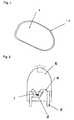
- a combination of plural colors is required to make white light, different from monochromatic light, and a general white LED is composed of a combination of an ultraviolet LED or a blue LED with a phosphor emitting visible light with the LED as an excitation source.
- a general white LED is composed of a combination of an ultraviolet LED or a blue LED with a phosphor emitting visible light with the LED as an excitation source.
- One of the known methods for synthesizing such phosphors for example, in a case of ⁇ -sialon powder, is a reduction and nitridation method wherein a powder mixture of aluminum oxide (Al 2 O 3 ), silicon oxide (SiO 2 ), an oxide of a metal or an element capable of making a solid solution in the lattice, and so on is subjected to a heat treatment in a nitrogen atmosphere in the presence of carbon (cf. Non-patent Documents 4 to 6).
- This method has merits that raw-material powders are inexpensive and the synthesis can be carried out at a relatively low temperature around 1500°C.
- this method goes through plural intermediates on the way of the synthesis and generates gas components such as SiO and CO, and it is thus difficult to obtain a phosphor in a single phase, to severely control the composition, and to control particle sizes.
- the ⁇ - or ⁇ -sialon powder can be obtained by firing a mixture of silicon nitride, aluminum nitride, an oxide of a metal or an element capable of making a solid solution in the lattice thereof, and so on at a high temperature and pulverizing the obtained sintered body.
- a high temperature and pulverizing the obtained sintered body there was a problem that the luminescence intensity of the phosphor was decreased by the pulverizing operation of the sintered body as described below.
- the phosphor for the white LED is generally used as dispersed in the form of micron-size particles in a sealant such as epoxy.
- a sealant such as epoxy.
- the dispersion state and compatibility with the sealant significantly affect the efficiency of extraction of LED light.
- surface coating of the phosphor is also being studied for improvement in the luminous efficiency of the phosphor and prevention of degradation, but its effect is different depending on the phosphors; there is a case not showing any effect at all and the effect was thus uncertain (Patent Documents 7 to 9).
- the nitrides and oxynitrides have larger refractive indices and smaller specific gravities than the oxide phosphors such as YAG:Ce conventionally used for the white LEDs, and they failed to provide a satisfactory luminescence property as an LED when used in the same manner as the oxide phosphors.
- Patent Document 1 JP-A-2002-363554
- Patent Document 2 JP-A-2003-336059
- Patent Document 3 JP-A-2003-124527
- Patent Document 4 JP-A-2003-206481
- Patent Document 5 JP-A-2004-186278
- Patent Document 6 JP-A-2004-244560
- Patent Document 7 JP-A-2001-303037
- Patent Document 8 JP-A-2000-204368
- Patent Document 9 International Publication WO96/09353 Pamphlet
- Non-Patent Document 1 J. W. H.
- Non-Patent Document 2 Extended Abstracts (The 65th Autumn Meeting, September, 2004, Tohoku Gakuin University) No. 3, p.1282-1284; The Japan Society of Applied Physics
- Non-Patent Document 3 Extended Abstracts (The 52nd Spring meeting, March, 2005, Saitama University) No. 3, p.1615; The Japan Society of Applied Physics and Related Societies
- Non-Patent Document 4 M. Mitomo et al., "Preparation of ⁇ -SiAlON Powders by Carbothermal Reduction and Nitridation," Ceram.
- Non-Patent Document 5 J. W. T. van Rutten et al., "Carbothermal Preparation and Characterization of Ca- ⁇ -SiAlON,” J. Eur. Ceram. Soc., 15,599-604 (1995 )
- Non-Patent Document 6 K. Komeya et al., "Hollow Beads Composed of Nanosize Ca ⁇ -SiAlON Grains,” J. Am. Ceram, Soc., 83,995-997 (2000 )
- the conventional techniques had the problem that the powder of the nitride phosphor or oxynitride phosphor could not be obtained as a phosphor powder with a satisfactory property, by simply mixing and heating nitrides containing constituent elements and a compound containing an activating element or by simply reduction-nitriding a mixture of oxides of constituent elements in the presence of carbon or the like.
- a pulverization treatment under severe conditions is required in order to obtain the powder with desired particle sizes because coalescences between particles become stronger by liquid-phase sintering during the firing step.
- a chance of incorporation of impurities becomes larger and a defect is introduced into a surface of each particle.
- the phosphor is excited in the vicinity of its surface with excitation light to emit fluorescent light, and the surface defects introduced by the pulverization treatment significantly affect the fluorescence property and raised the problem of degradation of the luminescence property.
- the nitride powder contains oxygen as an unavoidable impurity and there are two types of oxygen; oxygen existing in the form of a solid solution in the particles and oxygen existing in the form of oxide coating films on surfaces of the particles.
- Amounts of the oxygen existing in the particles hereinafter referred to as “solid solution oxygen”
- surface oxygen the oxygen existing on the surfaces
- the nitrides and oxynitrides have larger refractive indices and smaller specific gravities than the oxide phosphors such as YAG:Ce conventionally used for the white LEDs, and failed to provide a satisfactory luminescence property as an LED when used in the same manner as the oxide phosphors.
- the luminous efficiency of the ⁇ -sialon phosphor has been improved with attention mainly to the composition of the solid solution such as the substitutional amount of Al-N and Al-0 bonds into the ⁇ -silicon nitride forming a framework of the crystal and a kind, an amount and a ratio of the element penetrating into the crystal lattice to make the solid solution, and the factors other than the composition have not been studied much.
- the ⁇ -sialon sintered body obtained by firing at a high temperature is pulverized to obtain the ⁇ -sialon powder, and there was a problem that the luminescence intensity of the phosphor was decreased due to impurities adhering to the ⁇ -sialon powder, depending on the pulverizing operation.
- a phosphor for a white LED is generally used as dispersed in the form of micron-size particles in a sealant such as an epoxy resin. It is necessary to determine the particle sizes in terms of dispersibility into the resin and variation in coloring.
- the ⁇ -sialon phosphor is composed of secondary particles resulting from sintering of plural fine primary particles. In general, particle size information obtained by measurement of a particle size distribution is that about the secondary particles, and there were studies on the secondary particles in application to the phosphor. However, no attention has been paid to the primary particles.
- the present invention has been accomplished to solve the above problems and an object of the present invention is to provide a sialon phosphor excellent in the luminous efficiency and a light emitting device using it, particularly a white LED excellent in the luminous efficiency with a blue LED or ultraviolet LED as a light source.
- the present inventors conducted various experimental studies on the nitride phosphors and oxynitride phosphors, and found that the fluorescence property of the phosphor is largely affected, particularly, by properly combining various factors such as an amount of oxygen in the phosphor, a condition of surfaces of the phosphor particles, surface coating, and a sealant resin, thereby achieving the present invention.
- the present invention has been accomplished based particularly on the finding as a result of various studies on ⁇ -sialons that an ⁇ -sialon with a specific structure has a peak at a wavelength in the range of from 550 to 600 nm, is excellent in the luminous efficiency, and is suitably applicable to an LED, particularly a white LED excellent in the luminous efficiency with a blue light LED or ultraviolet LED as a light source.
- the present invention provides a powdery phosphor comprising an ⁇ -sialon represented by the formula: (M1) X (M2) Y (Si) 12-(m+n) (Al) m+n (O) n (N) 16-n
- M1 is at least one element selected from the group consisting of Li, Mg, Ca, Y and lanthanide metals (except for La and Ce)
- M2 is at least one element selected from Ce, Pr, Eu, Tb, Yb and Er, 0.3 ⁇ X+Y ⁇ 1.5, 0 ⁇ Y ⁇ 0.7, 0.6 ⁇ m ⁇ 3.0, 0 ⁇ n ⁇ 1.5
- X+Y m/2, wherein the oxygen content in a powder of the ⁇ -sialon is larger than a value based on the formula, in a range of less than 0.4 mass% of said value.
- a phosphor which is a powdery phosphor comprising particles of a metal nitride or oxynitride, wherein a transparent film is formed on at least a part of a surface of each particle of the metal nitride or oxynitride and in a thickness of (10 to 180)/n (unit: nanometer) is also disclosed.
- n is a refractive index of the transparent film and is from 1.2 to 2.5. In a preferred embodiment , n is from 1.5 to 2.0.
- the transparent film is preferably formed in the same manner on at least a part of the surface of the sialon particle as well.
- the present invention provides a phosphor, wherein the above formula is (Ca,Eu) m/2 (Si) 12-(m+n) (Al) m+n (O) n (N) 16-n , an Eu content is from 0.1 to 0.35 at%, lattice constant a is from 0.780 to 0.790 nm and lattice constant c is from 0.560 to 0.580 nm.
- M1 contains at least Ca and M2 contains at least Eu; and it is more preferred that the above M1 is Ca and the above M2 is Eu.
- the above-mentioned phosphor is preferably a phosphor in which M1 contains at least Ca, M2 contains at least Eu, and 0.01 ⁇ Y/(X+Y) ⁇ 0.3; and which has a luminescence property with a peak in a wavelength range of from 550 to 600 nm when irradiated with ultraviolet or visible light having a maximum intensity of emission wavelengths in a range of from 100 to 500 nm.
- an average particle size of powder particles of the ⁇ -sialon is from 1 to 20 ⁇ m, and it is more preferred that a content of an impurity other than the elements constituting the ⁇ -sialon is at most 1 mass%.
- the present invention provides a light emitting device comprising, as constituent elements, the above-mentioned phosphor and an LED with a maximum intensity of emission wavelength in a range of from 240 to 480 nm.
- This light emitting device is preferably one in which the LED and the nitride or oxynitride phosphor are implanted in the same resin layer with a refractive index of from 1.58 to 1.85 and in which a surface of the resin layer is covered with a resin with a refractive index of from 1.3 to 1.58.
- the present invention provides an illumination instrument comprising a luminescent light source and a phosphor, in which the phosphor used is at least one of the above-mentioned phosphors.
- the above phosphor to be used is preferably selected from a phosphor in which M1 contains at least Ca, M2 contains at least Eu, and 0.01 ⁇ Y/(X+Y) ⁇ 0.3; and which has a luminescence property with a peak in a wavelength range of from 550 to 600 nm when irradiated with ultraviolet or visible light of wavelengths of from 100 to 500 nm as an excitation source, and a phosphor which has a luminescence property with a peak in a wavelength range of from 500 to 550 nm when irradiated with ultraviolet or visible light of wavelengths of from 100 to 500 nm as an excitation source.
- the present invention provides an illumination instrument comprising a luminescent light source and a phosphor, wherein the above phosphor used is a phosphor comprising an ⁇ -sialon represented by the formula: (Ca,Eu) m/2 (Si) 12-(m+n) (Al) m+n (O) n (N) 16-n , having an Eu content of from 0.1 to 0.35 at%, lattice constant a of from 0.780 to 0.790 nm and lattice constant c of from 0.560 to 0.580 nm, and in this illumination instrument the phosphor is preferably irradiated with ultraviolet or visible light as an excitation source.
- the above phosphor used is a phosphor comprising an ⁇ -sialon represented by the formula: (Ca,Eu) m/2 (Si) 12-(m+n) (Al) m+n (O) n (N) 16-n , having an Eu content of from 0.1 to
- M1 is at least one element selected from the group consisting of Li, Mg, Ca, Y and lanthanide metals (except for La and Ce)
- M2 is at least one element selected from Ce, Pr, Eu, Tb, Y
- the present invention provides the phosphor production process further comprising performing an acid treatment of the phosphor, after production of the phosphor.
- the preferred phosphor of the present invention comprises a nitride or oxynitride or an ⁇ -sialon of the specific composition in which the oxygen content is specified, and optionally the phosphor has a structure in which a transparent material with the predetermined refractive index is formed in the predetermined thickness on at least a part of a surface of each of the particles constituting the phosphor, whereby the present invention achieves the effect that the phosphor of the present invention has a superior fluorescence property to the conventional phosphors, particularly, a superior luminescence property in the range of from 400 to 700 nm. Accordingly, the phosphor can be suitably applied to various LEDs, and in particular, an excellent white LED can be obtained in combination with an LED having the maximum intensity of luminescence wavelengths in the range of from 240 to 480 nm.
- the ⁇ -sialon of the specific structure according to the present invention is efficiently excited by ultraviolet or visible light of wavelengths of from 100 to 500 nm, particularly, by visible light of wavelengths of from 440 to 480 nm to emit light with a peak in the range of from 550 to 600 nm, and therefore it is suitable for various illumination instruments and, particularly, for a white LED using a blue LED or an ultraviolet LED as a light source, while achieving a high energy efficiency by virtue of the excellent luminescence property.
- the illumination instrument of the present invention uses the phosphor comprising the above ⁇ -sialon, it undergoes less change in luminance even in use at high temperatures and can achieve a longer lifetime; particularly, when the luminescent light source use is a blue LED which can emit visible light of from 440 to 480 nm, white light can be readily obtained by a combination of the light from the luminescent light source with the luminescence from the ⁇ -sialon, and thus it is applicable to various applications.
- the phosphor having the above-mentioned features can be produced stably and in large quantity.
- the present inventors conducted various experimental studies on the nitride phosphors and oxynitride phosphors and accomplished the present invention to secure an excellent fluorescence property by (1) using an ⁇ -sialon of a specific composition and limiting its oxygen content to a specific value. Moreover, (2) adopting a structure in which a transparent material with a predetermined refractive index is formed in a predetermined thickness on at least a part of a surface of the nitride phosphor or oxynitride phosphor; (3) specifying a composition of an ⁇ -sialon and a size and shape of its primary particles; or (4) specifying a composition and a crystal structure of an ⁇ -sialon are also disclosed.
- the preferred phosphor of the present invention comprises an ⁇ -sialon of a specific composition.
- the ⁇ -sialon is represented by the formula: (M1) X (M2) Y (Si) 12-(m+n) (Al) m+n (O) n (N) 16-n
- M1 is at least one element selected from the group consisting of Li, Mg, Ca, Y and lanthanide metals (except for La and Ce)
- M2 is at least one element selected from Ce, Pr, Eu, Tb, Yb and Er
- the ⁇ -sialon of this composition is important for obtaining a phosphor excellent in a fluorescence property.
- Ca is preferably selected as M1 in the above-mentioned composition because it is inexpensive and achieves a stable fluorescence property.
- Eu is selected as M2 because of its excellent fluorescence property.
- the lower limit of Y is preferably at least 0.01, more preferably at least 0.02, and the upper limit of Y is preferably at most 0.5, more preferably at most 0.3. If Y exceeds the upper limit (0.5) relative to X+Y, it will lead to occurrence of so-called concentration quenching to decrease the luminescence intensity of the phosphor, and increase in cost because Eu is expensive. On the other hand, if Y is less than 0.01 relative to X+Y, it will lead to decrease in the number of luminescent centers and reduction in the luminance.
- the phosphor has a configuration wherein an amount of oxygen contained in the ⁇ -sialon powder of the above-mentioned specific composition is larger than a value calculated based on the above formula, in a range of less than 0.4 mass%, preferably 0.25 mass%, more preferably 0.15 mass%, and this configuration achieves the effect that the fluorescence property thereof is superior to those of the conventional phosphors.
- the lower limit thereof is preferably at least 0.8 mass%, more preferably at least 1.0 mass% and the upper limit thereof is preferably at most 2.5 mass%, more preferably at most 2.0 mass%.
- the fluorescence property of the phosphor is improved by providing it with the structure in which the specific transparent film in the predetermined thickness is formed on at least a part of the surface of each of particles constituting the nitride or oxynitride phosphor, i.e., based on the finding that the fluorescence property of the phosphor can be enhanced by forming the transparent film of the predetermined material in the predetermined thickness on the surface of each particle.
- the present inventors conducted studies on the transparent film formed on the surface of each particle, and found the following tendencies: there is an appropriate thickness range for the transparent film; if the film is thinner than a certain thickness, it becomes difficult to form the transparent film with high uniformity and it will result in weakening the effects such as the reduction in defects in surfaces of the phosphor particles and the prevention of reflection of light to excite the phosphor (referred to simply as "excitation light"), on the surfaces of the particles; on the other hand, if the film is too thick, the film itself will absorb light to decrease the luminous efficiency of the phosphor. In addition, in order to obtain an excellent fluorescence property with high repeatability, it is insufficient to simply determine the thickness and it is preferred to determine the thickness, also taking the refractive index of the transparent film into consideration.
- the phosphor is a powdery phosphor comprising particles of a metal nitride or oxynitride, which has a structure in which a transparent film with a refractive index n (1.2 to 2.5) is formed on at least a part of a surface of each constituent particle thereof and in a thickness of (10 to 180)/n (unit: nanometer, n: the refractive index of the transparent film).
- the transparent film is preferably and ideally formed over the entire surface of the particle. This structure is observed with a scanning electron microscope, as illustrated in Fig. 1 . In this example, the entire surface of the nitride or oxynitride phosphor 9 is covered with the transparent film 10. It is, however, noted that the effect of the present invention is achieved as long as a part of the particle surface, about a half or more of the particle surface, is covered.
- the material making the above transparent film may be any transparent material with the refractive index n of from 1.2 to 2.5 (particularly preferably, one having transparency with a transmission coefficient of at least 80% in a region of ultraviolet to blue light, particularly, from 240 to 480 nm, depending on applications).
- Specific examples of such materials include inorganic substances such as silica, titania, alumina, magnesia and magnesium fluoride, and resins such as polystyrene, polycarbonate and polymethylstyrene. Among them, it is preferable to select one of the inorganic materials, in order to bring about the effect of reducing the defects in the surface of the phosphor.
- the phosphor when used for an LED and the like, there are many examples of use in which the phosphor is implanted into a resin, and in this case, a layer of the above transparent film lies between the resin and the surface of the phosphor.
- the refractive index of the transparent film is optically desired to have a value between the refractive indices of the above resin and the particles constituting the phosphor.
- the refractive index of silicon nitride is 2.0 and an epoxy resin widely used as a sealant resin in the LED and a silicone resin under study for the ultraviolet LED both have the refractive indices around 1.5.
- the refractive index of the transparent film is preferably in a range of from 1.5 to 2.0, more preferably from 1.6 to 1.9. Specific examples of such materials include magnesia and alumina.
- magnesia has the refractive index of around 1.75 and the thickness of the film is preferably set to from 5 to 100 nm; in use of the phosphor for the ultraviolet excitation-type white LED, the thickness of the transparent film is set to from 5 to 70 nm, preferably from 10 to 60 nm; in use of the phosphor for the blue excitation-type white LED, the thickness of the transparent film is set to from 10 to 100 nm, preferably from 15 to 80 nm.
- a main component of the blue or ultraviolet emitting device is gallium nitride and it is known that its refractive index is extremely large, about 2.4 to 2.5.
- a resin covering the phosphor (a resin in which the phosphor is implanted) is usually the same as the resin covering the light emitting device.
- a resin with a high refractive index such as a polycarbonate resin, a fluorene epoxy resin, a fluorene silicone resin, a phenylsilane silicone resin and a sulfur-based epoxy resin.
- a resin having a low refractive index in order to increase the efficiency of extracting light to the outside of the light emitting device.
- resins include an epoxy resin, a silicone resin, a fluorine resin, a fluorine epoxy resin, and so on.
- a light emitting device with a high luminous efficiency can be constructed when it has the following structure: the transparent film with the refractive index of from 1.6 to 1.9 such as alumina or magnesia is formed on the surface of the phosphor (constituent particles); it is mixed with a resin having the refractive index of 1.58 to 1.85, i.e., a resin having a relatively high refractive index such as a fluorene epoxy resin; a semiconductor device (light emitting diode) is sealed with the mixture; the periphery of the sealant material is further surrounded by a resin having the refractive index of 1.3 to 1.58, e.g., a resin having a relatively low refractive index such as a fluorine epoxy resin.
- the present invention is directed to an LED including, as constituent elements, the above phosphor and an LED element with the maximum intensity of luminescence wavelengths in the range of from 240 to 480 nm.
- the LED shows an excellent luminous efficiency while reflecting the excellent fluorescence property of the phosphor as described above.
- the phosphor in which the transparent film is formed on at least a part of a surface of each phosphor constituent particle is preferred because it shows a higher luminous efficiency; and the phosphor in which the transparent film layer has the refractive index of from 1.6 to 1.9 is further preferred because it shows the intrinsic excellent fluorescence property of the phosphor even in application to the LED where the phosphor is implanted into a resin.
- An ⁇ -sialon is synthesized by using and heating a mixture of raw materials in which (a) silicon nitride, (b) at least either of aluminum nitride and aluminum oxide, (c) a compound containing M1 and (d) a compound containing M2 are appropriately mixed so as to have a predetermined composition.
- the present invention is characterized in that the raw materials containing oxygen as little as possible are used in order to satisfy the conditions that the oxygen content is 0 ⁇ n ⁇ 1.5 and the oxygen content is larger than a value calculated based on the formula, in the range of less than 0.4 mass%, as described above.
- one of the processes for producing a phosphor of the present invention is characterized by using (a) silicon nitride, (b) aluminum nitride, (c) a compound containing Ca and (d) a compound containing M2 as raw materials, and by using a calcium compound containing no oxygen, as the above (c) the compound containing Ca.
- specific examples of the calcium compound containing no oxygen include calcium chloride, calcium sulfide, calcium cyanamide and calcium carbide.
- the compound containing Ca is a combination of a calcium compound containing no oxygen, with a calcium compound containing oxygen.
- the calcium compound containing no oxygen may be calcium chloride, calcium sulfide, calcium nitride, calcium cyanamide or calcium carbide as described above and the calcium compound containing oxygen may be, for example, calcium oxide, calcium hydroxide, calcium carbonate, calcium sulfate or calcium nitrate.
- the ratio of the former to the latter is preferably at least 0.5 time larger in terms of the molar ratio of Ca. This is because such a composition prevents degradation of the fluorescence property of the resulting phosphor due to increase of the oxygen amount with use of a raw material containing much oxygen.
- the oxygen amount in the mixture is preferably small. According to the studies by the present inventors, if the oxygen amount in the mixture of raw materials is at most 4 mass%, the phosphor satisfying the above conditions can be surely obtained, such being preferred.
- the phosphor ( ⁇ -sialon) is preferably subjected further to an acid treatment in the present invention.
- the oxygen content of the phosphor can be decreased by the acid treatment of the phosphor, and as a result, the fluorescence property can be improved. Addition of this operation realizes an effect that a phosphor further excellent in the fluorescence property can be stably obtained.
- An acid used in the acid treatment may be an ordinary acid, and is preferably an acid capable of removing an oxide of silicon, such as hydrofluoric acid, or a mixed acid such as hydrofluoric acid-nitric acid or hydrofluoric acid-hydrochloric acid.
- the present inventors experienced that the oxygen amount in the phosphor was sometimes lower than the value obtained by calculation in which analysis values of the metal components were applied to the formula. In this case, no excellent fluorescence property is obtained. Namely, it is believed that when the actual oxygen amount is lower than the oxygen amount obtained from the formula, a phase different from the ⁇ -sialon must exist even though no crystal phase other than the ⁇ -sialon is confirmed by X-ray diffraction, and it is the cause of the failure in achievement of a satisfactory fluorescence property.
- a method for forming the transparent film on the surface of the phosphor one of the conventionally known various methods such as a wet method, a CVD method, sputtering, a vapor deposition method and a spray-pyrolysis technique, can be used, and the wet method and the spray-pyrolysis technique are preferred among them because they are simple in apparatus and advantageous in cost.
- a wet method a CVD method, sputtering, a vapor deposition method and a spray-pyrolysis technique
- the wet method and the spray-pyrolysis technique are preferred among them because they are simple in apparatus and advantageous in cost.
- An example of the wet method will be explained below.
- the process for producing a phosphor is a process comprising suspending in an organic solvent such as an alcohol, a nitride or oxynitride phosphor, such as a phosphor comprising the ⁇ -sialon having the desired composition as described above; dropwise adding an organic metal complex or a metal alkoxide, and an alkaline solution in the suspension to form a film of a metal oxide or hydroxide on a surface of each particle of the phosphor; and, thereafter, if necessary, firing the particles in air or in an inert gas such as nitrogen gas to form a transparent film in a predetermined thickness on at least a part of a surface of each particle of the ⁇ -sialon constituting the phosphor.
- the thickness of the transparent film formed on the surface of the particle can be readily controlled by controlling the condition of the dropwise addition, so that the phosphor excellent in the fluorescence property can be stably obtained with high repeatability.
- Another preferred embodiment of the wet method is a method comprising suspending the above phosphor constituent particles in water; and dropwise adding an aqueous solution of a metal salt with a pH being kept constant, to form a transparent film in a thickness of (10 to 180)/n (unit: nanometer) on at least a part of a surface of each particle of the ⁇ -sialon constituting the phosphor.
- n is a refractive index of the transparent film and is from 1.2 to 2.5.
- the phosphor constituent particles are suspended in an alkaline, acid or buffer solution with the controlled pH with use of a stirrer or ultrasonic dispersion machine, and the aqueous solution of the metal salt is dropwise added to form a film of an oxide or hydroxide of the metal on the surface of the phosphor, followed by filtration, washing and drying, and, if necessary, by a heat treatment in air or in an inert gas such as nitrogen gas.
- the particles are treated with a silane coupling agent, preferably, with an epoxy-type silane coupling agent after forming the transparent film, which improves adhesion between the phosphor and a resin in which the phosphor is implanted during production of an LED, which also improves the dispersibility of the phosphor in the above resin, and as a result, which improves properties of the LED.
- the phosphor of the present example is characterized in that the above formula is (M1) x (M2) y (Si,Al) 12 (O,N) 16 , where 0.3 ⁇ X+Y ⁇ 1.5 and 0 ⁇ Y ⁇ 0.7, an average aspect ratio of the primary particles constituting the powder of the above ⁇ -sialon particle is at most 3, and diameters of at least 80% (percentage by particle number) of the above primary particles are from 3 to 10 ⁇ m.
- This phosphor will be explained below.
- the ⁇ -sialon is a solid solution wherein some of SiN bonds in an ⁇ -silicon nitride are substituted with Al-N bonds and Al-0 bonds and a specific cation penetrates into the lattice in order to maintain electrical neutrality, and it is represented by the formula: M z (Si,Al) 12 (O,N) 16 .
- M is an element that can penetrate into the lattice and, specifically, is at least one element selected from Li, Mg, Ca, Y and lanthanide metals (except for La and Ce).
- An amount of solved M, Z-value is a value determined by a substitution rate of Si-N bonds with Al-N and Al-O bonds.
- the formula becomes (M1) X (M2) Y (Si,Al) 12 (O,N) 16 .
- the formula preferably satisfies the ranges of 0.3 ⁇ X+Y ⁇ 1.5 and 0 ⁇ Y ⁇ 0.7, in order to obtain the single phase of the ⁇ -sialon and to develop the fluorescence property.
- the ⁇ -sialon is usually obtained by heating a powder mixture comprising silicon nitride, aluminum nitride and a compound of an element penetrating to make a solid solution, at a high temperature in an nitrogen atmosphere to cause reaction, as described above. In the course of raising the temperature, substances migrate through a liquid phase composed of silicon nitride, aluminum nitride, oxides on their surfaces and the compound of the element for the solid solution, to form an ⁇ -sialon.
- some primary particles are sintered to form secondary particles, and they further form agglomerates; therefore, they are subjected to pulverization or the like to obtain the ⁇ -sialon in the form of powder.
- the phosphor of this example was obtained based on the finding that the sizes, distribution and shape of the primary particles are closely associated with the luminescence property, as a result of studies on the relation between the luminescence property and the particle form.
- the phosphor of the present invention is made to select the following conditions, in addition to the above-mentioned composition: with respect to the primary particles constituting the powdery phosphor, an average aspect ratio thereof is at most 3 and at least 80% thereof in terms of percentage by particle number have the diameter of from 3 to 10 ⁇ m.
- the average aspect ratio is at most 2.5 and at least 85% in terms of percentage by particle number have the diameter of from 3 to 10 ⁇ m.
- the anisotropy is preferably small, for example, from the viewpoint of dispersibility in the sealant resin for the LED, the luminescence intensity of the LED, and variation in color tone.
- the phosphor can be used without any practical problem as long as the average aspect ratio of the primary particles is at most 3.
- the average aspect ratio of the primary particles may be determined by measuring aspect ratios (long-axis diameter/short-axis diameter) of at least 500 primary particles with a scanning electron microscope (SEM) and calculating an arithmetic mean thereof.
- a distribution of sizes of the primary particles is preferably sharp. If the size distribution of primary particles is wide, variation might occur in the luminescence intensity and in color tone in use of the phosphor. On the other hand, if the primary particles are too small, optical absorptance will decrease because scattering and sintering will strongly proceed between particles, so as to require an excessive pulverization treatment to obtain predetermined particle sizes of powder (secondary particles), which, in turn, will raise problems that the luminescence property is deteriorated due to production of defects in the surfaces of the particles and that handleability becomes poor.
- the present invention is arranged to select the condition of the sizes of the primary particles that at least 80% in terms of percentage by particle number of the primary particles have the diameter of from 3 to 10 ⁇ m.
- the percentage by particle number is determined by measuring circle-equivalent diameters of at least 500 primary particles with a scanning electron microscope (SEM) and calculating the percentage, as described below.
- a relation between a trace-amount element and the luminescence property of the ⁇ -sialon phosphor in the present invention is carried out, and found the following fact: a better luminescence property is obtained as a preferred result when the phosphor contains fluorine in an amount of from 5 to 300 ppm, preferably from 20 to 270 ppm, or boron in an amount of from 10 to 3000 ppm, preferably from 200 to 1000 ppm.
- This phenomenon becomes outstanding with at least 5 ppm of fluorine or with at least 10 ppm of boron, but no improvement in the effect can be made with more than 300 ppm of the former or with more than 3000 ppm of the latter.
- the phosphor may contain both of fluorine and boron. Boron can be measured by ICP emission spectrometry and fluorine can be measured by ion chromatography analysis.
- a method of adding a trace amount of fluorine or boron there are no particular limitations on a method of adding a trace amount of fluorine or boron, and a preferred method for fluorine is to use a fluoride as one or more of the raw materials and to volatilize excessive fluorine during the synthesis.
- a preferred method for boron is to use a hexagonal boron nitride crucible as a crucible to be filled with the powder mixture of raw materials during the synthesis and to utilize a boron-containing volatile substance produced in a trace amount from the crucible at a high temperature, as a technique for uniformly adding a trace amount of boron.
- the fluorine content in the ⁇ -sialon can be controlled by volatilizing a part of the fluorine compound in the raw materials as a volatile fluorine-containing substance in a heat treatment described below, or by removing the remaining fluorine compound by a treatment with an acid such as hydrochloric acid or sulfuric acid after the heat treatment.
- the phosphor is irradiated with ultraviolet or visible light of wavelengths in the range of from 100 to 500 nm as the excitation source whereupon the phosphor emits light of yellow to orange with a peak in the wavelength range of from 550 to 600 nm.
- This phosphor is preferred since a white LED is obtained by mixing yellow light emitted from the phosphor, with the excitation light in use of a blue LED as the excitation source, thereby providing illumination instruments emitting white light, such as the white LED.
- an atomic weight ratio of Eu becoming the luminescent centers is preferably in the range of 0.01 ⁇ Y/(X+Y) ⁇ 0.3.
- Y/(X+Y) exceeds 0.01, the number of luminescent centers is enough to prevent reduction in the luminance; when it is less than 0.3, the luminance would not decrease by concentration quenching due to interference between Eu ions in the solid solution.
- the phosphor of this example uses powders of silicon nitride, aluminum nitride, a calcium-containing compound and europium oxide as raw materials.
- a fluorine source among these raw materials it is preferred to use calcium fluoride, because the fluoride has a relatively high boiling point.
- calcium fluoride is used as the whole calcium source, it becomes difficult to obtain a single phase of the ⁇ -sialon. Therefore, it is preferred to mix a compound to become calcium oxide after heating, e.g., calcium carbonate.
- An applicable method for mixing the above raw materials may be a method of dry mixing, and a method of wet mixing in an inert solvent that does not substantially react with each component of the raw-materials, followed by removal of the solvent.
- a mixing apparatus suitably used is a V-type mixer, a rocking mixer, a ball mill, a vibration mill, or the like.
- Powders obtained by mixing in a desired composition are filled in a container such as a crucible at least a surface of which to be brought into contact with the raw-material powders is made of boron nitride, and heated in a temperature range of from 1600 to 1800°C in a nitrogen atmosphere for a predetermined time to obtain an ⁇ -sialon.
- a container such as a crucible at least a surface of which to be brought into contact with the raw-material powders is made of boron nitride, and heated in a temperature range of from 1600 to 1800°C in a nitrogen atmosphere for a predetermined time to obtain an ⁇ -sialon.
- boron nitride is used as the material for the container, is not only that the reactivity with each of the raw-material components is extremely low, but also that a trace amount of a boron-containing volatile component evolved from the container has an effect to promote crystal growth of the primary particles of the ⁇ -sialon.
- a mixture of the raw-material powders is preferably so filled in the container that the bulk is set as high as possible, from the viewpoint of suppression of sintering between particles during the heating.
- a filling rate of the mixture of the raw-material powders in the synthesizing container is preferably at most 40 mass%.
- the temperature of the heat treatment is at least 1600°C, there remain not many non-reacted products, and insufficient growth of the primary particles can be avoided; on the other hand, when the temperature is at most 1800°C, sintering between particles is not so outstanding; therefore, such a temperature range is preferred.
- a time range is so selected as to avoid the problems that there remain many non-reacted products and that growth of the primary particles is insufficient, or the problem that sintering between particles occurs.
- the preferred range of the heating period is from 2 to 24 hours approximately.
- the ⁇ -sialon obtained by the above process is an agglomerate, which is powdered into a predetermined size by a combination of crushing, pulverizing, and, if necessary, a classifying treatment, to obtain a powdery phosphor applicable for various applications.
- an average particle size of the secondary particles made by sintering of plural primary particles is preferably from 3 to 20 ⁇ m.
- the average particle size of the secondary particles is at least 3 ⁇ m, decrease in luminescence intensity can be avoided; when the average particle size is at most 20 ⁇ m, the particles are readily uniformly dispersed in a resin for sealing the LED, and variation can be suppressed in luminescence intensity and in color tone; such particles are suitable for practical use.
- the ⁇ -sialon agglomerate obtained by the above production method has a relatively high pulverizability and can be easily pulverized to predetermined particle sizes by a mortar or the like, but it is a matter of course that pulverizing means permitted for use herein include general pulverizing apparatus such as a ball mill, a vibration mill and a jet mill.
- the ⁇ -sialon in this example is represented by the formula: (Ca,Eu) m/2 (Si) 12-(m+n) (Al) m+n (O) n (N) 16-n , and in order to obtain the ⁇ -sialon in a single phase and developing the fluorescence property, the formula preferably satisfies the ranges of 0.6 ⁇ m ⁇ 3.0 and 0 ⁇ n ⁇ 1.5; the luminescence property described below is ensured in the ranges.
- the ⁇ -sialon of this example is a phosphor represented by the formula:
- the ⁇ -sialon represented by the above formula might not show a sufficient luminescence property.
- a phosphor excellent, particularly, in the luminescence property can be obtained when the Eu content in the ⁇ -sialon is from 0.1 to 0.35 at%, the lattice constant a is from 0.780 to 0.790 nm and the lattice constant c is from 0.560 to 0.580 nm.
- the ⁇ -sialon of this example with the lattice constant a of from 0.784 to 0.787 nm and the lattice constant c of from 0.569 to 0.572 nm can be obtained by strictly defining its composition as described below in Examples. Namely, raw materials are blended so as to satisfy the Eu content of from 0.1 to 0.35 at%, and then fired while controlling an atmosphere for the firing, to synthesize the ⁇ -sialon. Furthermore, when the conditions of 0.6 ⁇ m ⁇ 3.0 and 0 ⁇ n ⁇ 1.5 are satisfied, the ⁇ -sialon with the lattice constants in the above specific ranges can be readily obtained.
- the ⁇ -sialon is generally obtained by heating a powder mixture comprising silicon nitride, aluminum nitride and a compound of an element penetrating to make a solid solution, at a high temperature in an nitrogen atmosphere to cause reaction, as described above. In the course of raising the temperature, substances migrate through a liquid phase composed of silicon nitride, aluminum nitride, oxides on their surfaces and the compound of the element for the solid solution, to form an ⁇ -sialon.
- some primary particles are sintered to form secondary particles, and they further form agglomerates; therefore, they are subjected to pulverization or the like to obtain the ⁇ -sialon in the form of powder suitable for the phosphor.
- the ⁇ -sialon of this example after the synthesis, undergoes similar sintering of plural primary particles to produce secondary particles and agglomerates, and thus they are subjected to crushing, pulverizing, etc. to obtain a powdery phosphor of the ⁇ -sialon.
- the powdery phosphor of the ⁇ -sialon obtained by pulverizing and/or crushing as described above shows a higher luminescence property when the average particle size of the particles constituting the ⁇ -sialon powder is from 1 to 20 ⁇ m.
- the reason is as follows.
- the average particle size of the particles is within the above range, the following problems can be avoided: too fine particles scatter light to decrease the optical absorptance; too coarse particles cause variation in the luminescence intensity and in color tone.
- the synthesized or pulverized ⁇ -sialon powder is susceptible to incorporation of various impurities in the course of the production process. Based on the result of the present inventors' studies, the ⁇ -sialon powder is practically applicable without decrease in luminescence intensity when an amount of the impurities other than the constituent elements is at most 1 mass% in the ⁇ -sialon powder.
- the phosphor of the present invention ( ⁇ -sialon) has a wide excitation range of from ultraviolet to visible light and emits visible light, and it is thus suitable for light emitting devices and illumination instruments.
- the phosphor resulting from selection of Ca and Eu as the elements penetrating into the crystal lattice of the ⁇ -sialon has a high-intensity luminescence property of yellow to orange light with a peak wavelength in the range of from 550 to 600 nm.
- the ⁇ -sialon of the present invention is used as a phosphor for a light emitting device comprising an luminescent light source and the phosphor as constituent elements or as a phosphor for an illumination instrument comprising the light emitting device; particularly, when the excitation source is visible light containing wavelengths of 440 to 480 nm, the phosphor shows the luminescence property with a peak in the wavelength range of from 550 to 600 nm, and thus has a feature of readily providing white light in combination with a blue LED.
- the ⁇ -sialon is not deteriorated even under exposure to high temperatures and it is also excellent in heat resistance and in long-term stability under an oxidation atmosphere and a humid environment, whereby the illumination instrument, reflecting these, has features of high luminance and a long life.
- the illumination instrument of the present invention comprises at least one luminescent light source and the phosphor of the present invention.
- the illumination instrument of the present invention include an LED, a fluorescent lamp, and so on, and an LED can be produced with the phosphor of the present invention by one of the known methods, for example, as described in JP-A-5-152609 , JP-A-7-99345 , Japanese Patent No. 2927279 , and so on.
- these light emitting devices include those made of nitride semiconductors such as GaN and InGaN, and they can be used as the light emitting source emitting light of the predetermined wavelengths, based on adjustment of the composition.
- the phosphor of the present in the illumination instrument can also be used in combination with another phosphor having a different luminescence property, so as to constitute an illumination instrument emitting light of a desired color.
- a blue LED is used as the excitation source
- the phosphor of the present invention when the phosphor of the present invention is combined with another phosphor emitting from green to yellow light with a peak wavelength in the range of from 500 to 550 nm, it achieves emission of white light with a wide color temperature range.
- a phosphor may be a ⁇ -sialon in which Eu makes a solid solution.
- a red phosphor such as CaSiAlN 3 :Eu, it achieves an improvement in the color rendering property.
- Fig. 2 is a cross-sectional view of a shell-type LED as an example of the light emitting device of the present invention.
- reference numeral 1 designates a resin material containing a phosphor, 2 a semiconductor device part, 3 a lead frame, 4 a wire, and 5 a shell-type transparent resin.
- the phosphor of the present invention is combined with the semiconductor device part 2 in a mixed state in the phosphor-containing resin material 1 to constitute a white LED.
- Fig. 3 is a cross-sectional view of another example of the light emitting device of the present invention.
- This light emitting device has such a configuration that a semiconductor device part 2 placed on the bottom of a container 15 is covered with a resin layer 7 in which the phosphor 6 of the present invention is implanted, and that the upper surface of the resin layer 7 is sealed with a sealant resin 8.
- An ⁇ -sialon of this example had a composition of raw-material powders composed of 83.0 parts by mass of a silicon nitride powder (manufactured by Denki Kagaku Kogyo Kabushiki Kaisha, 9FW grade), 10.5 parts by mass of an aluminum nitride powder (manufactured by Tokuyama Corporation, F grade), 1.5 parts by mass of a europium oxide powder (manufactured by Shin-Etsu Chemical Co., Ltd., RU grade) and 5.5 parts by mass of a calcium sulfide powder (manufactured by Wako Pure Chemical Industries, Ltd.).
- the above raw-material powders were mixed by a wet ball mill with a silicon nitride pot and balls in an ethanol solvent for three hours, and filtered and dried to obtain a powder mixture.
- An amount of oxygen in the powder mixture was measured by an oxygen analyzer manufactured by LECO Corporation and it was 1.2 mass%.
- 100 g of the powder mixture was filled in a boron nitride crucible with an inner diameter of 100 mm and a height of 60 mm, and subjected to a heat treatment in an electric furnace with a carbon heater in a nitrogen atmosphere at the atmospheric pressure and at 1750°C for 12 hours.
- the product thus obtained was crushed in an agate mortar and passed through a 45 ⁇ m-mesh sieve.
- a synthetic powder of an ⁇ -sialon phosphor was obtained by these operations.
- An amount of oxygen calculated based on the composition was 1.36 mass%.
- An amount of oxygen in the ⁇ -sialon phosphor obtained was measured with the oxygen analyzer manufactured by LECO Corporation and it was 1.40 mass%.
- a fluorescence property was measured by means of a spectrophotofluorometer manufactured by Hitachi, Ltd. and a peak wavelength of a luminescence spectrum measured with an excitation wavelength of 400 nm was 580 nm.
- the luminescence intensity at the peak wavelength in the present Example was defined as 100, and a luminescence intensity at a peak wavelength of a luminescence spectrum measured with an excitation wavelength of 400 nm was compared relative to it, for each of the other Examples and Comparative Examples.
- An ⁇ -sialon phosphor was produced in the same manner as in Example 1-1 except that 2.8 parts by mass of a calcium sulfide powder and 3.8 parts by mass of a calcium carbonate (hereinafter also referred to simply as "CaCO 3 ”) powder (manufactured by KANTO CHEMICAL CO., INC., a guaranteed reagent) were used instead of 5.5 parts by mass of a calcium sulfide (hereinafter also referred to simply as "CaS”) in the raw-material powders of Example 1-1.
- CaS calcium carbonate
- the molar ratio of CaS/CaC0 3 is 1.
- An amount of oxygen in the powder mixture of the raw-materials was 3.4 mass%.
- An amount of oxygen calculated based on the compositional formula was 1.36 mass%.
- An amount of oxygen in the ⁇ -sialon phosphor obtained was measured with the oxygen analyzer manufactured by LECO Corporation and it was 1.71 mass%.
- a fluorescence property was measured in the same manner as in Example 1-1 and a relative value of the luminescence intensity was 85, where that in Example 1-1 was defined as 100.
- An ⁇ -sialon phosphor was produced in the same manner as in Example 1-1 except that 7.6 parts by mass of a calcium carbonate powder (manufactured by KANTO CHEMICAL CO., INC., a guaranteed reagent) were used instead of 5.5 parts by mass of a calcium sulfide powder in the raw-material powders of Example 1-1. An amount of oxygen in the powder mixture of the raw materials was 5.6 mass%.
- An amount of oxygen calculated based on the composition was 1.36 mass%.
- An amount of oxygen in the ⁇ -sialon phosphor obtained was measured with the oxygen analyzer manufactured by LECO Corporation and it was 1.80 mass%. Furthermore, a relative value of the luminescence intensity was 65.
- a composition of raw-material powders was composed of 33.5 parts by mass of a silicon nitride powder (manufactured by Denki Kagaku Kogyo Kabushiki Kaisha, 9FW grade), 29.5 parts by mass of an aluminum nitride powder (manufactured by Tokuyama Corporation, F grade), 2.5 parts by mass of a europium oxide powder (manufactured by Shin-Etsu Chemical Co., Ltd., RU grade) and 35.0 parts by mass of calcium nitride (manufactured by Wako Pure Chemical Industries, Ltd.).
- the above raw-material powders were mixed by a wet ball mill with a silicon nitride pot and balls in an xylene solvent for three hours, and filtered and dried to obtain a powder mixture.
- 100 g of the powder mixture was filled in a boron nitride crucible with an inner diameter of 100 mm and a height of 60 mm, and subjected to a heat treatment in an electric furnace with a carbon heater in a nitrogen atmosphere at a pressure of 0.9 MPa at 1800°C for 12 hours.
- the product thus obtained was crushed in an agate mortar and passed through a 45 ⁇ m-mesh sieve, whereby a CaAlSiN 3 :Eu phosphor powder was obtained.
- a peak wavelength of a luminescence spectrum measured with an excitation wavelength of 400 nm was 650 nm.
- the luminescence intensity at the peak wavelength in the present example was defined as 100, and a luminescence intensity at a peak wavelength of a luminescence spectrum measured with an excitation wavelength of 400 nm was compared relative to it, for each of the other Examples and Comparative Examples.
- the phosphor thus obtained was observed with a transmission electron microscope, and the thickness of the magnesia film was found to be about 60 nm. A fluorescent spectrum was measured and the luminescence spectral intensity was 115 (Example 1-4).
- a magnesia film obtained in the same manner as above was subjected to measurement of a refractive index by means of a reflective film thickness monitor manufactured by OTSUKA ELECTRONICS CO., LTD. and the refractive index was 1.73.
- a phosphor with a magnesia coating film was obtained in the same manner as in Example 1-4 except that the amount of magnesium ethoxide was changed to 1.0 g.
- the phosphor thus obtained was observed by means of a transmission electron microscope, and the thickness of the magnesia film was about 110 nm.
- a fluorescent spectrum was measured and the luminescence spectral intensity was 96, where that in Comparative Example 1-2 was defined as 100.
- This example is an example of forming an alumina film as the transparent film on the surface of the ⁇ -sialon phosphor.
- 32 ml of 0.1 M sodium hydroxide was added to 50 ml of an aqueous solution of 0.1 M boric acid and 0.1 M calcium chloride, and diluted up to 100 ml with distilled water.
- 5.0 g of the ⁇ -sialon phosphor powder obtained in the same manner as in Example 1-1 was put into this aqueous solution and dispersed well.
- An alumina film obtained in the same manner as above was subjected to the measurement of the refractive index in the same manner as in Example 1-4, and it was 1.70.
- the present Example is an example of forming a silica film on the surface of the ⁇ -sialon phosphor.
- 5.0 g of an oxynitride phosphor powder obtained in the same manner as in Example 1-1 was dispersed well in a solution mixture of 50 ml of isopropanol and 20 ml of distilled water having 1.0 g of tetraethoxysilane dissolved therein. While sufficiently stirring the dispersion liquid, 50 ml of 15% aqueous ammonia was dropwise added and then reflux with heating was carried out under stirring for two hours. The slurry thus obtained was filtered, washed and dried, followed by firing at 600°C in a nitrogen atmosphere for one hour to obtain a phosphor with an amorphous silica coating film.
- the phosphor thus obtained was observed with a transmission electron microscope and the thickness of the silica film was found to be about 70 nm. A fluorescent spectrum was measured and the luminescent spectral intensity was 113, where that in Example 1-1 was defined as 100.
- a silica film obtained in the same manner as above was subject to the measuring of the refractive index in the same manner as in Example 1-4, and it was 1.48.
- a surface mount LED was prepared in the same manner as in Example 1-7, using an oxynitride phosphor with a silica coating film obtained in the same manner as in Example 1-6, and a luminescence spectrum was measured.
- Example 1-7 The intensity at 580 nm was 95 where that in Example 1-7 was defined as 100.
- Example 1-7 an epoxy resin (refractive index: 1.6) using a fluorene-type epoxy compound was subjected to potting and cured, and a fluorine-type coating agent (manufactured by Tokyo Sangyo Yoshi Co., Ltd., INT350, refractive index: 1.36) was applied to the surface to form a fluorine resin layer of about 1 ⁇ m.
- the intensity at 580 nm in the luminescence spectrum of this light emitting device was 108 where that in Example 1-7 was defined as 100.
- Example 1-4 10 g of a nitride phosphor obtained in the same manner as in Example 1-4, together with 1.0 g of an epoxy-based silane coupling agent, was added to 100 ml of distilled water and left overnight under stirring. Thereafter, it was filtered and dried and then subjected to the measurement of the luminescence spectrum.
- the luminescence intensity at 650 nm was 104, where that in Example 1-4 was defined as 100.
- a surface mount LED was produced in the same manner as in Example 1-7, using an oxynitride phosphor obtained in the same manner as in Example 1-1, without an alumina coating film.
- the luminescence spectral intensity of the LED at 580 nm was 75, where that in Example 1-7 was defined as 100.
- An oxynitride phosphor was prepared in the same manner as in Example 1-1 except that the composition of the raw-material powders was changed to 51.0 parts by mass of silicon nitride power, 30.0 parts by mass of aluminum nitride power, 3.1 parts by mass of europium oxide power (Shin-Etsu Chemical Co., Ltd., RU grade) and 17.0 parts by mass of calcium sulfide power.
- the powder thus obtained was analyzed by means of an X-ray diffractometer and many peaks not assigned to the ⁇ -sialon were detected.
- a relative value of the luminescence intensity at 580 nm was 50, where that in Example 1-1 was defined as 100.
- 100 g of the powder mixture was filled in a boron nitride crucible with an inner diameter of 100 mm and a height of 60 mm and subjected to a heat treatment in an electronic furnace with a carbon heater in a nitrogen atmosphere at 0.9 MPa, and at 1900°C for 12 hours, and a resultant product was crushed by means of an agate mortar and passed through a 45 ⁇ m-mesh sieve.
- a synthetic powder of a ⁇ -sialon phosphor was obtained by these operations.
- the fluorescence property was measured by means of a spectrophotofluorometer manufactured by Hitachi, Ltd. and the peak wavelength of the fluorescent spectrum was 540 nm when measured with an excitation wavelength of 400 nm.
- the powder was treated in the same manner as in Example 1-5, to form an aluminum oxide coating film on the surface and the fluorescence property was measured.
- a luminescence intensity of the phosphor powder with the coating film was 110, where that of the ⁇ -sialon phosphor powder without the coating film at 540 nm was defined as 100.
- the raw-material powders used were an ⁇ -silicon nitride powder (NP200 grade) manufactured by Denki Kagaku Kogyo Kabushiki Kaisha, an aluminum nitride powder (F grade) manufactured by Tokuyama Corporation, a calcium carbonate powder (guaranteed reagent) manufactured by KANTO CHEMICAL CO., INC., a calcium fluoride powder (guaranteed reagent) manufactured by Wako Pure Chemical Industries, Ltd. and a europium oxide powder (RU grade) manufactured by Shin-Etsu Chemical Co., Ltd., and they were blended in the composition as shown in Table 1 so as to obtain an ⁇ -sialon in a single phase after the synthesis.
- NP200 grade manufactured by Denki Kagaku Kogyo Kabushiki Kaisha
- an aluminum nitride powder F grade
- a calcium carbonate powder (guaranteed reagent) manufactured by KANTO CHEMICAL CO., INC.
- the raw-material powders blended were mixed in an isopropyl alcohol solvent by a wet ball mill with a plastic pot and silicon nitride balls, and the solvent was removed by a rotary evaporator to obtain a powder mixture.
- the powder thus obtained by the above operation was subjected to identification of crystal phases by the X-ray diffraction (XRD) method, quantification of crystal phases by the Rietveld analysis, and measurement of a particle size distribution of secondary particles by the laser diffraction scattering method. Furthermore, the powder was observed with a scanning electron microscope (SEM), and circle-equivalent diameters and aspect ratios (long-axis diameter/short-axis diameter) of primary particles were measured from an observation image thus obtained, thereby calculating a distribution of circle-equivalent diameters (a ratio of the number of primary particles with the circle-equivalent diameters of from 3 to 10 ⁇ m to the total number of the primary particles) and an average aspect ratio. The evaluation was carried out with respect to at least 500 primary particles.
- SEM scanning electron microscope
- a fluorescent spectrum was measured with blue light excitation (wavelength of 460 nm) by means of a spectrophotofluorometer and a peak intensity and a peak wavelength of the spectrum were determined from the spectrum. It is noted that the peak intensity changes depending on measuring apparatus and conditions, and the unit is an arbitrary unit. Examples and Comparative Examples were compared with values measured under the same condition.
- An amount of boron in the synthetic powder was measured by the ICP emission spectrometry and an amount of fluorine was measured by the following method.
- 0.5 g of a sample was introduced into a reaction tube at 1200°C, and subjected to hydrolysis with water vapor at 95 to 96°C, and the generated gas was absorbed in 10 ml of 0.05 mass% NaOH solution, followed by measurement by ion chromatography.
- Table 2 shows the results of the above-described evaluations.
- the synthetic powder was a single phase of the synthetic ⁇ -sialon and that the average particle size (secondary particles) was 10 pm. It was found from the result of the SEM observation that the particle form was such that plural relatively equiaxial micron-size primary particles were sintered together. The ratio of primary particles with circle-equivalent diameters from 3 to 10 ⁇ m was 92% and the average aspect ratio was 1.5. A boron content was 590 ppm and a fluorine content was 40 ppm. When excited with blue light of the wavelength of 460 nm, the phosphor emitted yellow-orange light with the peak wavelength of 587 nm.
- Examples 2-2 and 2-3 were prepared and evaluated in the same manner and procedure as in Example 2-1.
- Table 1 shows the compositions of raw-material powders and synthetic conditions, and Table 2 shows the evaluation results of the synthetic products.
- Comparative Examples 2-1 to 2-3 were prepared and evaluated in the same manner and procedure as in Example 2-1. It was, however, noted that in Comparative Example 2-2, a boron oxide powder manufactured by Wako Pure Chemical Industries, Ltd. was added by a content of 1 mass% as a part per hundred raw-material mixture, in addition to the raw-material powders in Example 2-1.
- Comparative Example 2-1 sizes of primary particles constituting the synthetic powder were as large as the order of from sub ⁇ m to a few ⁇ m and the ratio of primary particles with a circle-equivalent diameters from 3 to 10 ⁇ m was 40%.
- the peak wavelength of the luminescence spectrum was 590 nm, which was close to that in Example 2-1, but the luminescence intensity was approximately half.
- Comparative Example 2-2 a boron content was 4520 ppm and the peak wavelength of the luminescence spectrum was 588 nm, but the luminescence intensity was about 70% of that in Example 2-1.
- Example 2-1 10 g of an ⁇ -sialon phosphor obtained in Example 2-1 was added together with 1.0 g of an epoxy-type silane coupling agent (manufactured by Shin-Etsu Silicone, KBE402) to 100 g of water and the mixture was left overnight under stirring. Then an appropriate amount of the ⁇ -sialon phosphor treated with the silane coupling agent, after filtered and dried, was kneaded with 10 g of an epoxy resin (manufactured by SANYU REC CO. LTD, NLD-SL-2101), potted onto a blue LED with a luminescence wavelength of 460 nm, subjected to vacuum deaeration and cured under heating at 110°C to produce a surface mount LED.
- an epoxy-type silane coupling agent manufactured by Shin-Etsu Silicone, KBE402
- Fig. 4 shows a schematic structure of a white LED (the above-mentioned surface mount LED).
- the white LED is fabricated as follows: a blue LED chip 11 is connected to an electrically conductive terminal 16 and placed on the bottom of a container 15; the blue LED chip 11 is connected to another electrically conductive terminal 17 with a wire 3; then a mixture obtained by kneading an ⁇ -sialon phosphor 12 and a sealant resin (epoxy resin) 14 is potted onto the blue LED chip 11; and the sealant resin 14 is subjected to curing under heating.
- a luminescence spectrum of emitted light was measured while an electric current of 10 mA was applied to the surface mount LED.
- Table 3 shows the luminescence property and average color rendering index. An illumination instrument with a high luminance and a low correlated color temperature (incandescent color) was obtained.
- a surface mount LED was fabricated in the same manner as in Example 2-4, by mixing appropriate amounts of two kinds of the phosphor in Example 2-1 and a ⁇ -sialon doped with Eu showing yellow-green luminescence with the peak wavelength of 535 nm under excitation at the wavelength of 460 nm.
- Table 3 shows the luminescence property and average color rendering index.
- An illumination instrument obtained had a daylight color and a color rendering property higher than that in Example 2-4. TABLE 3 Lamp efficiency (lm/W) Chromaticity coordinate (CIE1931) Correlated color temperature (K) Average color rendering index Ra Color tone x Color tone y
- Example 4 40.0 0.454 0.408 2860 68.5
- Example 5 28.5 0.313 0.322 6450 85.0
- the raw-material powders used were an ⁇ -silicon nitride powder (9FW grade) manufactured by Denki Kagaku Kogyo Kabushiki Kaisha, an aluminum nitride powder (F grade) manufactured by Tokuyama Corporation, a calcium carbonate powder (guaranteed reagent) manufactured by KANTO CHEMICAL CO., INC., a calcium fluoride powder (guaranteed reagent) manufactured by Wako Pure Chemical Industries, Ltd. and a europium oxide powder (RU grade) manufactured by Shin-Etsu Chemical Co., Ltd., and they were blended so as to obtain an ⁇ -sialon in a single phase after the synthesis (cf.
- the above raw-material powders were mixed in a solvent of ethanol by a wet ball mill with a silicon nitride pot and balls for three hours, and the solvent was filtered by means of a rotary evaporator or the like and dried to obtain a powder mixture.
- 100 g of the powder mixture was filled in a boron nitride crucible with an inner diameter of 100 mm and a height of 85 mm and a heat treatment was carried out in an electric furnace with a carbon heater in a nitrogen atmosphere of the atmospheric pressure and at 1700°C for 12 hours.
- the product thus obtained was crushed with an agate mortar and passed through a 45 ⁇ m-mesh sieve. A synthetic powder was obtained by these operations.
- a fluorescent spectrum was measured with blue light excitation (wavelength of 460 nm) by means of a spectrophotofluorometer (F4500) manufactured by Hitachi High-Technologies Corporation and a peak intensity and a peak wavelength of the spectrum were determined from the spectrum. It is noted that the peak intensity changes depending on measuring apparatus and conditions, and the unit is an arbitrary unit. Examples and Comparative Examples were compared with values measured under the same condition. Table 5 shows the results of the above-described evaluations.
- An Eu content was obtained by composition analysis by means of a fluorescent X-ray analyzer (ZSX100e) manufactured by Rigaku Industrial Corporation and an O/N analyzer (TC-436) manufactured by LECO Corporation. The content was found to be 0.175 at%.
- Particles were subjected to measurement of a particle size distribution by the laser diffraction scattering method (using a measuring apparatus LS230 manufactured by Coulter Company).
- the average particle size (secondary particles) was 11.8 ⁇ m.
- the measurement method of measuring the lattice constants by the XRD diffraction there are no particular limitations on the measurement method of measuring the lattice constants by the XRD diffraction.
- a method of mixing and pulverizing a sample with an internal standard substance and measuring the lattice constants with an X-ray diffraction apparatus Aluminum oxide, magnesium oxide, silicon, and so on are generally used as the internal standard substance. However, it is preferred to use a substance whose peak does not overlap the peak of the sample.
- refinement of the lattice constants is conducted with use of analysis software of the lattice constants.
- An example of the analysis software is JADE manufactured by Rigaku Corporation.
- the lattice constant a was 0.781 nm
- the lattice constant c was 0.567 nm. It was noted that the lattice constant measurement was carried out based on JIS K0131.
- Raw materials were so blended that the value m of the ⁇ -sialon obtained became from 1.25 to 2, in the same manner and procedure as in Example 3-1 (cf. Table 4).
- the raw materials blended were treated in the same manner as in Example 3-1, to obtain various synthetic powders.
- Table 5 shows the results for these synthetic powders. With respect to the luminescence property, the peak intensities were high, among which Example 3-4 was highest. With respect to the lattice constant measurement, both the lattice constants a and c had large numeral values.
- Raw materials were so blended that the value m became 0.8 in Comparative Example 3-1 and 2.25 in Comparative Example 3-2, and that the value m was 1.75 and the Eu content was at least 0.35 at% in Comparative Example 3-3, in the same manner and procedure as in Example 3-1, and the same treatment as in Example 3-1 was conducted to obtain various synthetic powders.
- the synthetic powder obtained in Comparative Example 3-2 was pulverized for one minute by a vibration mill using a stainless-steel pot, then crushed in an agate mortar and passed through a 45 ⁇ m-mesh sieve.
- the phosphor of the present invention has a wide excitation range from ultraviolet to visible light and emits visible light, it is suitable for a light emitting device, particularly, for a white LED, and, when used in combination with an excitation light source of ultraviolet or visible light with the maximum intensity of luminescence wavelengths in the range of from 100 to 500 nm, preferably from 240 to 480 nm, it is suitably applicable as a phosphor for a light emitting device or an illumination instrument.
Claims (19)
- Luminophore pulvérulent comprenant un α-sialon représenté par la formule :
(M1)X(M2)Y(Si)12-(m+n) (Al)m+n(O)n(N)16-n,
où M1 est au moins un élément choisi parmi le groupe constitué de Li, Mg, Ca, Y et des métaux lanthanides (sauf pour La et Ce), M2 est au moins un élément choisi parmi Ce, Pr, Eu, Tb, Yb et Er, 0,3 ≤ X+Y ≤ 1, 5, 0 < Y, ≤ 0,7, 0,6 ≤ m ≤ 3,0, 0 < n ≤ 1,5 et X+Y = m/2, dans lequel la teneur en oxygène dans une poudre du α-sialon ci-dessus est supérieure à une valeur basée sur la formule ci-dessus, dans une plage de moins de 0,4 % en masse de ladite valeur. - Luminophore selon la revendication 1, dans lequel la formule ci-dessus est
(Ca, Eu)m/2(Si)12-(m+n) (Al)m+n(O)n(N)16-n,
une teneur en Eu est de 0,1 à 0,35 en %, la constante de réseau a est de 0,780 à 0,790 nm, et la constante de réseau c est de 0,560 à 0,580 nm. - Luminophore selon l'une quelconque des revendications 1 ou 2, dans lequel M1 contient au moins du Ca, et M2 contient au moins de l'Eu.
- Luminophore selon la revendication 3, dans lequel M1 est Ca et M2 est Eu.
- Luminophore selon l'une quelconque des revendications 1 à 4, qui contient du fluor en une quantité de 5 à 300 ppm.
- Luminophore selon l'une quelconque des revendications 1 à 5, qui contient du bore en une quantité de 10 à 3 000 ppm.
- Luminophore selon l'une quelconque des revendications 1 à 6, dans lequel M1 contient au moins du Ca, M2 contient au moins de l'Eu, et 0,01 < Y/(X+Y) < 0,3 ;
et qui présente une propriété de luminescence avec un pic dans une gamme de longueur d'onde de 550 à 600 nm lorsqu'il est soumis à une lumière ultraviolette ou visible présentant une intensité maximale de longueurs d'onde d'émission dans une plage de 100 à 500 nm. - Luminophore selon l'une quelconque des revendications 1 ou 2, dans lequel une granulométrie moyenne de particules de poudre de l'α-sialon ci-dessus est de 1 à 20 µm.
- Luminophore selon l'une quelconque des revendications 1 ou 2, dans lequel une teneur en une impureté autre que les éléments constituant l'α-sialon ci-dessus est d'au plus 1 % en masse.
- Procédé pour produire un luminophore comprenant un α-sialon représenté par la formule :
(Ca)X(M2)Y(Si)12-(m+n) (Al)m+n(O)n(N)16-n,
où M2 est au moins un élément choisi parmi Ce, Pr, Eu, Tb, Yb et Er, 0,3 ≤ X+Y ≤ 1,5, 0 < Y ≤ 0,7, 0,6 ≤ m ≤ 3,0, 0 ≤ n ≤ 1,5, et X+Y = m/2, dans lequel un composé de calcium ne contenant pas d'oxygène est utilisé comme matière première pour Ca. - Procédé pour produire un luminophore selon la revendication 10, dans lequel un composé de calcium contenant de l'oxygène est utilisé en combinaison avec le composé de calcium ne contenant pas d'oxygène, comme matière première pour Ca.
- Procédé pour produire un luminophore selon la revendication 11, dans lequel le composé de calcium ne contenant pas d'oxygène est utilisé à un rapport molaire d'au moins 0,5 fois le composé de calcium contenant de l'oxygène.
- Procédé pour produire le luminophore selon l'une quelconque des revendications 10 à 12, dans lequel la teneur totale en oxygène dans toutes les matières premières est d'au plus 4 % en masse.
- Procédé pour produire un luminophore selon l'une quelconque des revendications 10 à 13, comprenant en outre un traitement à l'acide du luminophore, après production du luminophore.
- Dispositif électroluminescent comprenant une source de lumière luminescente et un luminophore en tant qu'éléments constitutifs, dans lequel le luminophore est au moins un élément tel que défini dans l'une quelconque des revendications 1 à 9.
- Dispositif électroluminescent selon la revendication 15, dans lequel la source de lumière luminescente ci-dessus est une DEL présentant une intensité maximale de longueurs d'onde d'émission dans une plage de 240 à 480 nm.
- Dispositif électroluminescent selon la revendication 16, dans lequel la DEL et le luminophore tel que défini dans l'une quelconque des revendications 1 à 9 sont implantés dans une couche de résine dont l'indice de réfraction est de 1,58 à 1,85, et dans lequel une surface de la couche de résine est recouverte d'une résine présentant un indice de réfraction de 1,3 à 1,58.
- Instrument d'éclairage comprenant le dispositif électroluminescent tel que défini dans l'une quelconque des revendications 15 à 17.
- Instrument d'éclairage selon la revendication 18, dans lequel le luminophore utilisé est un luminophore dont une propriété de luminescence présente un pic dans une gamme de longueur d'onde de 500 à 550 nm lorsqu'il est soumis à une lumière ultraviolette ou visible de longueurs d'onde de 100 à 500 nm, en tant que source d'excitation.
Applications Claiming Priority (5)
| Application Number | Priority Date | Filing Date | Title |
|---|---|---|---|
| JP2005052270 | 2005-02-28 | ||
| JP2005118271A JP4512869B2 (ja) | 2005-02-28 | 2005-04-15 | 蛍光体とその製造方法、およびそれを用いた発光素子 |
| JP2005146917A JP4538739B2 (ja) | 2005-05-19 | 2005-05-19 | α型サイアロン蛍光体とそれを用いた照明器具 |
| JP2005304268A JP4364189B2 (ja) | 2005-10-19 | 2005-10-19 | α型サイアロン、α型サイアロンからなる蛍光体とそれを用いた照明器具 |
| PCT/JP2006/303730 WO2006093135A1 (fr) | 2005-02-28 | 2006-02-28 | Substance fluorescente et procédé de fabrication idoine, et élément luminescent utilisant ladite substance |
Publications (3)
| Publication Number | Publication Date |
|---|---|
| EP1854864A1 EP1854864A1 (fr) | 2007-11-14 |
| EP1854864A4 EP1854864A4 (fr) | 2010-10-06 |
| EP1854864B1 true EP1854864B1 (fr) | 2012-11-21 |
Family
ID=36941164
Family Applications (1)
| Application Number | Title | Priority Date | Filing Date |
|---|---|---|---|
| EP06714867A Expired - Fee Related EP1854864B1 (fr) | 2005-02-28 | 2006-02-28 | Substance fluorescente et procédé de fabrication idoine, et élément luminescent utilisant ladite substance |
Country Status (6)
| Country | Link |
|---|---|
| US (1) | US8125139B2 (fr) |
| EP (1) | EP1854864B1 (fr) |
| KR (1) | KR101115855B1 (fr) |
| CN (5) | CN101712870A (fr) |
| TW (1) | TWI411660B (fr) |
| WO (1) | WO2006093135A1 (fr) |
Cited By (1)
| Publication number | Priority date | Publication date | Assignee | Title |
|---|---|---|---|---|
| US9190580B2 (en) | 2012-11-05 | 2015-11-17 | Lg Innotek Co., Ltd. | Phosphor and light emitting device having the same |
Families Citing this family (66)
| Publication number | Priority date | Publication date | Assignee | Title |
|---|---|---|---|---|
| KR100900282B1 (ko) * | 2004-06-18 | 2009-05-29 | 도쿠리츠교세이호징 붓시쯔 자이료 겐큐키코 | α형 사이알론 및 α형 사이알론 형광체 및 그 제조 방법 |
| JP2007049114A (ja) | 2005-05-30 | 2007-02-22 | Sharp Corp | 発光装置とその製造方法 |
| WO2006134982A1 (fr) * | 2005-06-14 | 2006-12-21 | Denki Kagaku Kogyo Kabushiki Kaisha | Composition de résine et feuille contenant du phosphore, et élément à émission lumineuse utilisant celles-ci |
| DE112006001722B4 (de) * | 2005-07-01 | 2021-05-06 | National Institute For Materials Science | Leuchtstoff und Verfahren zu dessen Herstellung sowie Verwendung des Leuchtstoffs |
| US20070052342A1 (en) * | 2005-09-01 | 2007-03-08 | Sharp Kabushiki Kaisha | Light-emitting device |
| JP2007273506A (ja) * | 2006-03-30 | 2007-10-18 | Sumitomo Chemical Co Ltd | 化合物半導体発光素子 |
| EP3093327A3 (fr) | 2006-05-10 | 2017-05-03 | Denka Company Limited | Phosphore de sialon, son procédé de production, dispositif d'éclairage et élément luminescent l'utilisant |
| JP5378644B2 (ja) * | 2006-09-29 | 2013-12-25 | Dowaホールディングス株式会社 | 窒化物蛍光体または酸窒化物蛍光体の製造方法 |
| JP5227503B2 (ja) * | 2006-09-29 | 2013-07-03 | Dowaエレクトロニクス株式会社 | 蛍光体、蛍光体シート及び蛍光体の製造方法、並びに当該蛍光体を用いた発光装置 |
| JP5367218B2 (ja) | 2006-11-24 | 2013-12-11 | シャープ株式会社 | 蛍光体の製造方法および発光装置の製造方法 |
| JP5135812B2 (ja) * | 2007-02-05 | 2013-02-06 | 憲一 町田 | 窒化物又は酸窒化物を母体とする蛍光体、及びその製造方法、並びにそれを使用した蛍光体含有組成物、発光装置、照明装置、及び画像表示装置 |
| CN101755030B (zh) | 2007-05-22 | 2014-05-14 | 独立行政法人物质·材料研究机构 | 荧光体及其制造方法和使用该荧光体的发光装置 |
| CN101688115B (zh) | 2007-07-09 | 2013-03-27 | 夏普株式会社 | 荧光体粒子组以及使用其的发光装置 |
| JP5578597B2 (ja) | 2007-09-03 | 2014-08-27 | 独立行政法人物質・材料研究機構 | 蛍光体及びその製造方法、並びにそれを用いた発光装置 |
| US8518300B2 (en) | 2007-10-10 | 2013-08-27 | Ube Industries, Ltd. | β-sialon phosphor powder and production method thereof |
| DE102007056342A1 (de) * | 2007-11-22 | 2009-05-28 | Merck Patent Gmbh | Oberflächenmodifizierte Konversionsleuchtstoffe |
| US7939350B2 (en) | 2008-01-03 | 2011-05-10 | E. I. Du Pont De Nemours And Company | Method for encapsulating a substrate and method for fabricating a light emitting diode device |
| EP2314659B1 (fr) | 2008-08-13 | 2014-07-23 | Ube Industries, Ltd. | Substance fluorescence à base d alpha-sialon contenant du lithium et procédé de fabrication associé, dispositif d éclairage, et dispositif d affichage d image |
| US8287759B2 (en) | 2009-05-15 | 2012-10-16 | Cree, Inc. | Luminescent particles, methods and light emitting devices including the same |
| US9464225B2 (en) | 2008-11-17 | 2016-10-11 | Cree, Inc. | Luminescent particles, methods of identifying same and light emitting devices including the same |
| JP5641384B2 (ja) * | 2008-11-28 | 2014-12-17 | 独立行政法人物質・材料研究機構 | 表示装置用照明装置及び表示装置 |
| KR101732746B1 (ko) * | 2009-01-27 | 2017-05-04 | 덴카 주식회사 | α형 사이알론 형광체, 그의 제조법 및 발광 장치 |
| US9000664B2 (en) | 2009-04-06 | 2015-04-07 | Sharp Kabushiki Kaisha | Phosphor particle group, light emitting apparatus using the same, and liquid crystal display television |
| JP5330889B2 (ja) * | 2009-04-14 | 2013-10-30 | 電気化学工業株式会社 | 照明用ledモジュール |
| JP5388699B2 (ja) * | 2009-05-29 | 2014-01-15 | 電気化学工業株式会社 | α型サイアロン蛍光体およびそれを用いた発光素子 |
| KR101720822B1 (ko) | 2009-12-22 | 2017-03-28 | 미쓰비시 가가꾸 가부시키가이샤 | 반도체 발광 장치용 수지 성형체용 재료 |
| CN102782085B (zh) * | 2010-03-31 | 2014-06-25 | 宇部兴产株式会社 | 赛隆系氧氮化物荧光体的制造方法以及赛隆系氧氮化物荧光体 |
| CN102376860A (zh) | 2010-08-05 | 2012-03-14 | 夏普株式会社 | 发光装置及其制造方法 |
| JP5883390B2 (ja) * | 2010-09-09 | 2016-03-15 | デンカ株式会社 | β型サイアロンの製造方法 |
| TWI457418B (zh) * | 2010-09-29 | 2014-10-21 | Au Optronics Corp | 白光發光二極體裝置、發光裝置及液晶顯示器 |
| KR101866600B1 (ko) | 2011-01-26 | 2018-06-11 | 덴카 주식회사 | α 형 사이알론, 발광 장치 및 그 용도 |
| US8785222B2 (en) | 2011-05-09 | 2014-07-22 | Hong Kong Applied Science and Technology Research Institute Company Limited | Phosphor ink composition |
| US8729790B2 (en) | 2011-06-03 | 2014-05-20 | Cree, Inc. | Coated phosphors and light emitting devices including the same |
| US9290618B2 (en) | 2011-08-05 | 2016-03-22 | Sabic Global Technologies B.V. | Polycarbonate compositions having enhanced optical properties, methods of making and articles comprising the polycarbonate compositions |
| CN104205376B (zh) * | 2012-02-03 | 2018-04-27 | 沙特基础全球技术有限公司 | 发光二极管器件及用于生产其的包括转换材料化学的方法 |
| EP2819981B1 (fr) | 2012-02-29 | 2016-12-21 | SABIC Global Technologies B.V. | Polycarbonate à base de bisphénol a à faible teneur en soufre et contenant un produit chimique à base de matériaux de conversion, et articles fabriqués à partir de celui-ci |
| US9382477B2 (en) * | 2012-03-29 | 2016-07-05 | Ube Industries, Ltd. | Oxynitride phosphor powder |
| CN103375708B (zh) * | 2012-04-26 | 2015-10-28 | 展晶科技(深圳)有限公司 | 发光二极管灯源装置 |
| WO2014006987A1 (fr) * | 2012-07-04 | 2014-01-09 | シャープ株式会社 | Matériau fluorescent, revêtement fluorescent, substrat de phosphore, instrument électronique et emballage de led |
| CN104736664B (zh) * | 2012-10-17 | 2016-09-14 | 宇部兴产株式会社 | 波长转换部件及使用其的发光装置 |
| WO2014066784A1 (fr) | 2012-10-25 | 2014-05-01 | Sabic Innovative Plastics Ip B.V. | Dispositifs à diode électroluminescente, leurs procédés de fabrication et leurs utilisations |
| KR102142672B1 (ko) * | 2012-11-13 | 2020-08-07 | 덴카 주식회사 | 형광체, 발광소자 및 조명장치 |
| DE102013100429B4 (de) | 2013-01-16 | 2023-12-07 | Osram Gmbh | Verfahren zur Herstellung eines pulverförmigen Precursormaterials und Verwendung eines mit dem Verfahren hergestellten pulverförmigen Precursormaterials |
| AT513747B1 (de) * | 2013-02-28 | 2014-07-15 | Mikroelektronik Ges Mit Beschränkter Haftung Ab | Bestückungsverfahren für Schaltungsträger und Schaltungsträger |
| JP6288343B2 (ja) * | 2013-04-26 | 2018-03-07 | 日亜化学工業株式会社 | 蛍光体及びそれを用いた発光装置 |
| US9772086B2 (en) | 2013-05-29 | 2017-09-26 | Sabic Innovative Plastics Ip B.V. | Illuminating devices with color stable thermoplastic light transmitting articles |
| KR102098318B1 (ko) * | 2013-08-07 | 2020-04-08 | 엘지이노텍 주식회사 | 형광체 및 이를 구비한 발광 소자 |
| KR101471099B1 (ko) * | 2013-08-26 | 2014-12-10 | 김형수 | 알루미나를 이용한 led 형광체의 제조방법 |
| CN103865531B (zh) * | 2013-09-24 | 2015-10-14 | 厦门通士达新材料有限公司 | 一种橙黄色氮化物荧光材料及其制备方法 |
| JP6123611B2 (ja) * | 2013-09-26 | 2017-05-10 | 宇部興産株式会社 | 蛍光顔料及び蛍光顔料を用いた塗膜 |
| US10584281B2 (en) * | 2014-10-14 | 2020-03-10 | Pavle Radovanovic | Light emitting materials and systems and method for production thereof |
| JP6763387B2 (ja) * | 2015-08-19 | 2020-09-30 | 宇部興産株式会社 | 蛍光体及びその製造方法並びに発光装置 |
| US10385267B2 (en) | 2015-12-15 | 2019-08-20 | Nichia Corporation | Method for producing β-sialon fluorescent material |
| JP6160763B2 (ja) * | 2015-12-15 | 2017-07-12 | 日亜化学工業株式会社 | βサイアロン蛍光体の製造方法 |
| US11427758B2 (en) | 2015-12-15 | 2022-08-30 | Nichia Corporation | Method for producing β-sialon fluorescent material |
| JP6460056B2 (ja) | 2016-06-30 | 2019-01-30 | 日亜化学工業株式会社 | 窒化物蛍光体の製造方法 |
| JP6932679B2 (ja) | 2017-11-30 | 2021-09-08 | デクセリアルズ株式会社 | 被覆蛍光体、その製造方法、並びに、蛍光体シート、及び発光装置 |
| WO2019107080A1 (fr) | 2017-11-30 | 2019-06-06 | デクセリアルズ株式会社 | Phosphore revêtu, procédé pour le produire, feuille de phosphore, et dispositif électroluminescent |
| WO2019188630A1 (fr) * | 2018-03-29 | 2019-10-03 | デンカ株式会社 | CORPS FLUORESCENT α-SIALON ET DISPOSITIF ÉLECTROLUMINESCENT |
| JP6667025B1 (ja) | 2019-03-29 | 2020-03-18 | デンカ株式会社 | 蛍光体粒子、複合体、発光装置および蛍光体粒子の製造方法 |
| JP6667026B1 (ja) | 2019-03-29 | 2020-03-18 | デンカ株式会社 | 蛍光体粒子、複合体、発光装置および蛍光体粒子の製造方法 |
| JP6667027B1 (ja) | 2019-03-29 | 2020-03-18 | デンカ株式会社 | 蛍光体粉末、複合体および発光装置 |
| CN110655920A (zh) * | 2019-09-20 | 2020-01-07 | 北京科技大学 | 一种二价铕掺杂的α-sialon基长余辉发光材料及制备方法 |
| JP2021054899A (ja) | 2019-09-27 | 2021-04-08 | 日亜化学工業株式会社 | βサイアロン蛍光体の製造方法 |
| EP4293732A1 (fr) | 2022-01-20 | 2023-12-20 | Mitsubishi Chemical Corporation | Luminophore, dispositif électroluminescent, dispositif d'éclairage, dispositif d'affichage d'image et voyant lumineux pour véhicules |
| EP4293733A4 (fr) | 2022-01-20 | 2024-04-17 | Mitsubishi Chem Corp | Luminophore, dispositif électroluminescent, dispositif d'éclairage, dispositif d'affichage d'image et lampe d'affichage pour poste mobile |
Family Cites Families (37)
| Publication number | Priority date | Publication date | Assignee | Title |
|---|---|---|---|---|
| JPH05152609A (ja) | 1991-11-25 | 1993-06-18 | Nichia Chem Ind Ltd | 発光ダイオード |
| JPH0799345A (ja) | 1993-09-28 | 1995-04-11 | Nichia Chem Ind Ltd | 発光ダイオード |
| TW295672B (fr) | 1994-09-20 | 1997-01-11 | Hitachi Ltd | |
| DE19638667C2 (de) | 1996-09-20 | 2001-05-17 | Osram Opto Semiconductors Gmbh | Mischfarbiges Licht abstrahlendes Halbleiterbauelement mit Lumineszenzkonversionselement |
| JP2927279B2 (ja) | 1996-07-29 | 1999-07-28 | 日亜化学工業株式会社 | 発光ダイオード |
| JPH11214752A (ja) | 1998-01-21 | 1999-08-06 | Matsushita Electron Corp | 半導体発光装置 |
| JP3797812B2 (ja) | 1999-01-11 | 2006-07-19 | 日立マクセル株式会社 | 無機蛍光体およびその製造方法 |
| JP3840360B2 (ja) | 2000-04-24 | 2006-11-01 | 大電株式会社 | カラープラズマディスプレイパネル用青色蛍光体 |
| JP3668770B2 (ja) | 2001-06-07 | 2005-07-06 | 独立行政法人物質・材料研究機構 | 希土類元素を付活させた酸窒化物蛍光体 |
| JP3726131B2 (ja) | 2002-05-23 | 2005-12-14 | 独立行政法人物質・材料研究機構 | サイアロン系蛍光体 |
| DE10133352A1 (de) | 2001-07-16 | 2003-02-06 | Patent Treuhand Ges Fuer Elektrische Gluehlampen Mbh | Beleuchtungseinheit mit mindestens einer LED als Lichtquelle |
| DE10146719A1 (de) * | 2001-09-20 | 2003-04-17 | Patent Treuhand Ges Fuer Elektrische Gluehlampen Mbh | Beleuchtungseinheit mit mindestens einer LED als Lichtquelle |
| DE10147040A1 (de) | 2001-09-25 | 2003-04-24 | Patent Treuhand Ges Fuer Elektrische Gluehlampen Mbh | Beleuchtungseinheit mit mindestens einer LED als Lichtquelle |
| CA2447288C (fr) * | 2002-03-22 | 2011-10-04 | Nichia Corporation | Luminophore a base de nitrure et methode de preparation connexe, et dispositif electroluminescent |
| JP2003321675A (ja) * | 2002-04-26 | 2003-11-14 | Nichia Chem Ind Ltd | 窒化物蛍光体及びその製造方法 |
| KR100516934B1 (ko) | 2002-06-29 | 2005-09-26 | 엘지전자 주식회사 | 플라즈마 디스플레이 패널의 형광체 제조방법 |
| JP4207489B2 (ja) * | 2002-08-06 | 2009-01-14 | 株式会社豊田中央研究所 | α−サイアロン蛍光体 |
| ATE454718T1 (de) * | 2002-11-08 | 2010-01-15 | Nichia Corp | Lichtemissionsbauelement, leuchtstoff und verfahren zur herstellung eines leuchtstoffs |
| JP4529349B2 (ja) * | 2002-11-08 | 2010-08-25 | 日亜化学工業株式会社 | 窒化物系蛍光体および発光装置 |
| JP5138145B2 (ja) | 2002-11-12 | 2013-02-06 | 日亜化学工業株式会社 | 蛍光体積層構造及びそれを用いる光源 |
| JP4072632B2 (ja) | 2002-11-29 | 2008-04-09 | 豊田合成株式会社 | 発光装置及び発光方法 |
| US7074346B2 (en) * | 2003-02-06 | 2006-07-11 | Ube Industries, Ltd. | Sialon-based oxynitride phosphor, process for its production, and use thereof |
| JP4052136B2 (ja) | 2003-02-06 | 2008-02-27 | 宇部興産株式会社 | サイアロン系酸窒化物蛍光体およびその製造方法 |
| JP4066828B2 (ja) | 2003-02-06 | 2008-03-26 | 宇部興産株式会社 | サイアロン系酸窒化物蛍光体およびその製造方法 |
| JP4244653B2 (ja) | 2003-02-17 | 2009-03-25 | 日亜化学工業株式会社 | シリコンナイトライド系蛍光体及びそれを用いた発光装置 |
| JP4292255B2 (ja) * | 2003-03-18 | 2009-07-08 | 独立行政法人産業技術総合研究所 | α−サイアロン焼結体及びその製造方法 |
| KR100609830B1 (ko) | 2003-04-25 | 2006-08-09 | 럭스피아 주식회사 | 녹색 및 적색형광체를 이용하는 백색 반도체 발광장치 |
| JP3914987B2 (ja) | 2003-06-20 | 2007-05-16 | 独立行政法人物質・材料研究機構 | サイアロン蛍光体とその製造方法 |
| JP4661032B2 (ja) * | 2003-06-26 | 2011-03-30 | 日亜化学工業株式会社 | 発光装置及びその製造方法 |
| JP4165318B2 (ja) | 2003-07-16 | 2008-10-15 | 宇部興産株式会社 | サイアロン系蛍光体およびその製造方法 |
| JP2005052270A (ja) | 2003-08-01 | 2005-03-03 | Kyoraku Sangyo | パチンコ機の遊技球誘導構造 |
| KR20050016804A (ko) | 2003-08-04 | 2005-02-21 | 서울반도체 주식회사 | 발광 소자용 고휘도 형광체 구조 및 이를 사용하는 발광소자 |
| JP2005118271A (ja) | 2003-10-16 | 2005-05-12 | Samii Kk | 遊技情報管理システム |
| JP4124101B2 (ja) | 2003-11-12 | 2008-07-23 | 日産自動車株式会社 | エンジンの制御装置 |
| JP4307314B2 (ja) | 2004-04-16 | 2009-08-05 | パナソニック株式会社 | 負荷駆動回路 |
| JP4581120B2 (ja) | 2004-04-26 | 2010-11-17 | 独立行政法人物質・材料研究機構 | 酸窒化物粉末およびその製造方法 |
| KR100900282B1 (ko) | 2004-06-18 | 2009-05-29 | 도쿠리츠교세이호징 붓시쯔 자이료 겐큐키코 | α형 사이알론 및 α형 사이알론 형광체 및 그 제조 방법 |
-
2006
- 2006-02-28 WO PCT/JP2006/303730 patent/WO2006093135A1/fr active Application Filing
- 2006-02-28 CN CN200910208341A patent/CN101712870A/zh active Pending
- 2006-02-28 CN CN200910208339A patent/CN101712868A/zh active Pending
- 2006-02-28 KR KR1020077017685A patent/KR101115855B1/ko active IP Right Grant
- 2006-02-28 CN CN2009102083402A patent/CN101712869B/zh not_active Expired - Fee Related
- 2006-02-28 US US11/817,261 patent/US8125139B2/en not_active Expired - Fee Related
- 2006-02-28 EP EP06714867A patent/EP1854864B1/fr not_active Expired - Fee Related
- 2006-02-28 CN CN2011104607734A patent/CN102585810A/zh active Pending
- 2006-02-28 CN CN2009102083385A patent/CN101982891A/zh active Pending
- 2006-03-01 TW TW095106840A patent/TWI411660B/zh not_active IP Right Cessation
Cited By (1)
| Publication number | Priority date | Publication date | Assignee | Title |
|---|---|---|---|---|
| US9190580B2 (en) | 2012-11-05 | 2015-11-17 | Lg Innotek Co., Ltd. | Phosphor and light emitting device having the same |
Also Published As
| Publication number | Publication date |
|---|---|
| WO2006093135A1 (fr) | 2006-09-08 |
| CN101712868A (zh) | 2010-05-26 |
| TW200643148A (en) | 2006-12-16 |
| KR101115855B1 (ko) | 2012-03-08 |
| KR20070106507A (ko) | 2007-11-01 |
| CN101712870A (zh) | 2010-05-26 |
| US20090021141A1 (en) | 2009-01-22 |
| CN101712869B (zh) | 2013-04-10 |
| EP1854864A4 (fr) | 2010-10-06 |
| CN101982891A (zh) | 2011-03-02 |
| US8125139B2 (en) | 2012-02-28 |
| CN101712869A (zh) | 2010-05-26 |
| CN102585810A (zh) | 2012-07-18 |
| TWI411660B (zh) | 2013-10-11 |
| EP1854864A1 (fr) | 2007-11-14 |
Similar Documents
| Publication | Publication Date | Title |
|---|---|---|
| EP1854864B1 (fr) | Substance fluorescente et procédé de fabrication idoine, et élément luminescent utilisant ladite substance | |
| JP5193967B2 (ja) | 蛍光体とその製造方法、およびそれを用いた発光素子 | |
| EP2163595B1 (fr) | Substance fluorescente, procédé de production de celle-ci et dispositif émettant de la lumière utilisant celle-ci | |
| JP4512869B2 (ja) | 蛍光体とその製造方法、およびそれを用いた発光素子 | |
| TWI399422B (zh) | 螢光體、其製造方法及照明器具 | |
| KR101294555B1 (ko) | 형광체의 제조방법 | |
| JP5151980B2 (ja) | サイアロン系酸窒化物蛍光体およびその製造方法 | |
| TWI384053B (zh) | 螢光體、其製造方法及照明器具 | |
| EP1997865B1 (fr) | Luminophore, procede de production et dispositif electroluminescent | |
| EP1445295A1 (fr) | Phosphore d'oxynitrure de type sialon, son procédé de fabrication et usage | |
| JP2006089547A (ja) | 蛍光体とその製造方法および発光器具 | |
| JP2007332324A (ja) | サイアロン蛍光体とその製造方法、およびそれを用いた発光素子 | |
| EP3992264B1 (fr) | Corps fluorescent, son procédé de production, et dispositif électroluminescent l'utilisant | |
| JP2015514144A (ja) | 変換蛍光体および負の熱膨張係数を有する材料を含有する複合セラミック | |
| EP2767572A1 (fr) | Poudre fluorescente d'oxynitrure, poudre de nitrure de silicium pour fabrication de poudre fluorescente d'oxynitrure, et procédé de fabrication de poudre fluorescente d'oxynitrure | |
| JP2008208238A (ja) | 蛍光体及びその製造方法、並びにそれを備えた照明器具と画像表示装置 | |
| CN116018388A (zh) | 铕活化β型塞隆荧光体和发光装置 | |
| WO2023171504A1 (fr) | PARTICULES FLUORESCENTES DE SIALON DE TYPE β ACTIVÉES PAR EU, POUDRE FLUORESCENTE DE SIALON DE TYPE β ET DISPOSITIF ÉLECTROLUMINESCENT |
Legal Events
| Date | Code | Title | Description |
|---|---|---|---|
| PUAI | Public reference made under article 153(3) epc to a published international application that has entered the european phase |
Free format text: ORIGINAL CODE: 0009012 |
|
| 17P | Request for examination filed |
Effective date: 20070828 |
|
| AK | Designated contracting states |
Kind code of ref document: A1 Designated state(s): DE GB IT |
|
| DAX | Request for extension of the european patent (deleted) | ||
| RBV | Designated contracting states (corrected) |
Designated state(s): DE GB IT |
|
| RBV | Designated contracting states (corrected) |
Designated state(s): DE GB IT |
|
| A4 | Supplementary search report drawn up and despatched |
Effective date: 20100903 |
|
| 17Q | First examination report despatched |
Effective date: 20110714 |
|
| GRAP | Despatch of communication of intention to grant a patent |
Free format text: ORIGINAL CODE: EPIDOSNIGR1 |
|
| GRAS | Grant fee paid |
Free format text: ORIGINAL CODE: EPIDOSNIGR3 |
|
| GRAA | (expected) grant |
Free format text: ORIGINAL CODE: 0009210 |
|
| AK | Designated contracting states |
Kind code of ref document: B1 Designated state(s): DE GB IT |
|
| REG | Reference to a national code |
Ref country code: GB Ref legal event code: FG4D |
|
| REG | Reference to a national code |
Ref country code: DE Ref legal event code: R096 Ref document number: 602006033188 Country of ref document: DE Effective date: 20130117 |
|
| PLBE | No opposition filed within time limit |
Free format text: ORIGINAL CODE: 0009261 |
|
| STAA | Information on the status of an ep patent application or granted ep patent |
Free format text: STATUS: NO OPPOSITION FILED WITHIN TIME LIMIT |
|
| 26N | No opposition filed |
Effective date: 20130822 |
|
| REG | Reference to a national code |
Ref country code: DE Ref legal event code: R097 Ref document number: 602006033188 Country of ref document: DE Effective date: 20130822 |
|
| PGFP | Annual fee paid to national office [announced via postgrant information from national office to epo] |
Ref country code: IT Payment date: 20160222 Year of fee payment: 11 |
|
| PGFP | Annual fee paid to national office [announced via postgrant information from national office to epo] |
Ref country code: GB Payment date: 20160224 Year of fee payment: 11 |
|
| GBPC | Gb: european patent ceased through non-payment of renewal fee |
Effective date: 20170228 |
|
| PG25 | Lapsed in a contracting state [announced via postgrant information from national office to epo] |
Ref country code: IT Free format text: LAPSE BECAUSE OF NON-PAYMENT OF DUE FEES Effective date: 20170228 Ref country code: GB Free format text: LAPSE BECAUSE OF NON-PAYMENT OF DUE FEES Effective date: 20170228 |
|
| PGFP | Annual fee paid to national office [announced via postgrant information from national office to epo] |
Ref country code: DE Payment date: 20220105 Year of fee payment: 17 |
|
| P01 | Opt-out of the competence of the unified patent court (upc) registered |
Effective date: 20230512 |
|
| REG | Reference to a national code |
Ref country code: DE Ref legal event code: R119 Ref document number: 602006033188 Country of ref document: DE |
|
| PG25 | Lapsed in a contracting state [announced via postgrant information from national office to epo] |
Ref country code: DE Free format text: LAPSE BECAUSE OF NON-PAYMENT OF DUE FEES Effective date: 20230901 |