EP1848298B1 - Poignee de baton - Google Patents
Poignee de baton Download PDFInfo
- Publication number
- EP1848298B1 EP1848298B1 EP06701539A EP06701539A EP1848298B1 EP 1848298 B1 EP1848298 B1 EP 1848298B1 EP 06701539 A EP06701539 A EP 06701539A EP 06701539 A EP06701539 A EP 06701539A EP 1848298 B1 EP1848298 B1 EP 1848298B1
- Authority
- EP
- European Patent Office
- Prior art keywords
- hand
- fastening
- eccentric element
- pole grip
- grip
- Prior art date
- Legal status (The legal status is an assumption and is not a legal conclusion. Google has not performed a legal analysis and makes no representation as to the accuracy of the status listed.)
- Active
Links
- 241000253999 Phasmatodea Species 0.000 claims abstract description 4
- 210000005224 forefinger Anatomy 0.000 claims description 2
- 210000003813 thumb Anatomy 0.000 claims description 2
- 239000002759 woven fabric Substances 0.000 claims 2
- 210000000707 wrist Anatomy 0.000 description 14
- 239000000463 material Substances 0.000 description 6
- 230000007246 mechanism Effects 0.000 description 6
- 239000000243 solution Substances 0.000 description 5
- 238000010276 construction Methods 0.000 description 4
- 239000004744 fabric Substances 0.000 description 3
- 230000005484 gravity Effects 0.000 description 2
- 238000007788 roughening Methods 0.000 description 2
- 229910052782 aluminium Inorganic materials 0.000 description 1
- XAGFODPZIPBFFR-UHFFFAOYSA-N aluminium Chemical compound [Al] XAGFODPZIPBFFR-UHFFFAOYSA-N 0.000 description 1
- 230000001419 dependent effect Effects 0.000 description 1
- 230000000694 effects Effects 0.000 description 1
- 238000001746 injection moulding Methods 0.000 description 1
- 230000010354 integration Effects 0.000 description 1
- 230000003993 interaction Effects 0.000 description 1
- 230000013011 mating Effects 0.000 description 1
- 229910052751 metal Inorganic materials 0.000 description 1
- 239000002184 metal Substances 0.000 description 1
Images
Classifications
-
- A—HUMAN NECESSITIES
- A45—HAND OR TRAVELLING ARTICLES
- A45B—WALKING STICKS; UMBRELLAS; LADIES' OR LIKE FANS
- A45B9/00—Details
- A45B9/02—Handles or heads
-
- A—HUMAN NECESSITIES
- A63—SPORTS; GAMES; AMUSEMENTS
- A63C—SKATES; SKIS; ROLLER SKATES; DESIGN OR LAYOUT OF COURTS, RINKS OR THE LIKE
- A63C11/00—Accessories for skiing or snowboarding
- A63C11/22—Ski-sticks
- A63C11/222—Ski-stick handles or hand-straps
- A63C11/2224—Connection systems for hand-straps
-
- A—HUMAN NECESSITIES
- A45—HAND OR TRAVELLING ARTICLES
- A45B—WALKING STICKS; UMBRELLAS; LADIES' OR LIKE FANS
- A45B9/00—Details
- A45B9/02—Handles or heads
- A45B2009/025—Handles or heads releasably connected to a wrist strap or a glove
-
- A—HUMAN NECESSITIES
- A45—HAND OR TRAVELLING ARTICLES
- A45B—WALKING STICKS; UMBRELLAS; LADIES' OR LIKE FANS
- A45B2200/00—Details not otherwise provided for in A45B
- A45B2200/05—Walking sticks
- A45B2200/055—Walking sticks for Nordic walking
Definitions
- the present invention relates to a pole grip with a hand-held device, in particular for walking sticks, trekking poles, alpine skis, cross-country poles, Nordic Walking poles, with a handle body and with a device for adjustable attachment of a hand-held device, in particular in the form of a wrist strap or a glove.
- Such a device may for example be designed such that a wrist strap is attached via a screw or a wedge on the pole handle, and the screw or the wedge provides an easy way to adjust the length of the wrist strap as possible without the aid of a tool to the needs of the user ,
- Such mechanical devices should be as reliable as possible, and do not permit undesirable adjustment of the length of the loop during use. They should also allow adjustment without complicated manipulations, and they should be extremely simple in their construction to keep costs down. On the other hand, such attachment mechanisms, this is particularly important in the alpine area very important to be able to perceive this releasable locking function in the widest possible temperature range.
- Such a construction is for example from the German utility model DE 681 01 226 U1 known.
- a loop on the floor is adjustably fastened by the loop tape is guided around two pins in the attachment area in the floor.
- a tiltable element which is arranged at the head of the stick handle, and in which these two pins are arranged. If this tilting element is folded upwards out of a recess in the pole grip, the length of the hand strap can be adjusted. If the tilting element again down into the stick handle at least partially folded into it, the hand strap is fixed in its length.
- the DE 29520269 discloses a construction for length adjustment of a wrist strap, in which the hand strap length is fixed by a guided through a slot of the hand strap threaded screw presses the guided around a clamping element hand strap against the bottom of a pole grip recess.
- the adjustability is then given when the hand strap is moved up, while in downward hand strap the hand strap is fixed in length.
- Such possibilities are for example in the DE 19632718 , of the DE 29906612 U1 , as well as similar in the EP 1118362 described.
- the EP 1053770 discloses a stick handle with an adjustable thereto provided hand strap.
- the length adjustment of the hand strap is determined by a lever, which is arranged in the head area of the pole grip. If the lever from the pole handle folded out, the strap of the hand strap can be adjusted in length, the lever is folded down, so the band between a pivotally mounted on the lever so-called pawl and an underlying flat counter surface is clamped.
- This pawl is formed as a triangular element which is pivotally mounted at the top in the lever, and which clamped with the tip surface opposite the flat surface against said flat mating surface.
- the band extends with its free end either in a specifically designated recess in the pole handle or it protrudes forward out of the pole grip. The free end thus extends further on the side of the pawl opposite the hand-holding device and either forward out of the stick handle or into the stick handle.
- the document FR2573318 relates to a pole grip with a the entire front the stick handle forming lever, which can be folded to clamp the stick handle.
- the lever clamps the tape against an area formed as a level of the stick handle and the free end is led down below the lever out of the stick handle.
- the invention is therefore based on the object to provide an alternative pole grip to those of the prior art.
- it is about to improve a pole handle for walking sticks, trekking poles, alpine skis, cross-country poles, Nordic walking poles, which has a handle body and a device for adjustable attachment of a hand-holding device, in particular in the form of a wrist strap or a glove.
- the hand-holding device for attachment to the pole grip at least in a mounting region has a fastening means in the form of a belt, a belt, a belt or a fabric strand, and that the device to a Has axis rotatable and / or pivotable eccentric, which eccentric in the mounting region has a surface whose radius is increasing to the axis in the locking direction, so that guided in the mounting area between this surface of the eccentric and a fixed abutment fastener by rotation or pivoting of the eccentric in the locking direction clamped between eccentric and abutment.
- the surface of the eccentric element can be continuous and, to a certain extent, smoothly increasing, but it can also be increasingly, ribbed or stepped at least in sections.
- An essential element of the invention is thus to use an eccentric element for fixing the fastening means.
- This extremely simple structural element proves to be surprisingly efficient for releasably fixing a fastener in the form of a belt, a belt, a belt or a fabric strand, since it can be solved without excessive force to adjust the length of the hand-held device on the pole grip, and there on the other hand preferably allows to actually fix the length of the hand-held device, substantially independent of the position of the hand-held device.
- An eccentric element can be integrated well in the pole grip and is very reliable, and the orientation of the eccentric element can preferably be chosen so that in a pull on the hand-held device it is pulled into its fixed position, that is to say in a pull on the hand-held device the attachment mechanism even more attached.
- the invention is further characterized in that the axis of the eccentric element is arranged substantially perpendicular to the pulling direction of the fastening means and particularly preferably substantially perpendicular to the pole axis. If the eccentric element is arranged in such a way, the forces which occur on the handheld holding device can be optimally absorbed by the eccentric element, and it is simultaneously possible to release the eccentric element for changing the distance of the handheld holding device from the pole grip without great effort.
- the eccentric element is an eccentrically mounted cylinder, since then an optimal interaction with a strip-shaped or band-shaped hand holding device in the fastening region can be achieved against an abutment across the width of the cylinder.
- the eccentric element has a manipulable from the outside lever or folding handle, by means of which the eccentric element can be rotated or pivoted to clamp the hand-held device.
- the folding handle is folded to release the attachment of the hand holding device upwards, and folded for clamping the attachment of the hand holding device forward or backward, so that the lever is arranged substantially horizontally in the locked position.
- the folding handle in a fixed position on the pole handle the least and hardly interferes with the use of the stick.
- lever or the folding handle on the upper side of the pole grip, and is preferably integrated in the locking position at least partially or in particular almost completely in the outer contour of the grip body. At least the tip should be exposed so that it is freely accessible for loosening (eg also with gloves).
- the invention is characterized by particularly practical integration in the pole grip, namely by the handle body from the hand side at the upper end has a recess which has a continuous opening to the top of the pole grip, in which the eccentric particularly preferably with a guided on both sides in the grip body Axle pin is stored.
- the eccentric element is preferably not arranged entirely in this opening, but protrudes into the recess. It is also possible to arrange the eccentric element in the recess and to let pass only the folding handle through the opening.
- the abutment is formed as in the recess in the form of a arranged below the eccentric element web or pin, which is supported on both sides in the handle body, and which is particularly preferably arranged parallel to the axis of the eccentric element.
- the entire locking device is almost completely integrated in the pole grip, as long as the folding lever is in its locking position, that is essentially horizontal. It is also possible to arrange the folding lever at the front edge, then a folded position is vertically conceivable.
- the recess has for example a height in the range of 12-15 mm, and a width of 10-15 mm, but can, for example, in cross-country skis or Nordic walking poles, which may be slightly slimmer, even smaller designed.
- the hand-held device has, as already mentioned above, for clamping between the eccentric element and the abutment at least over a portion (fastening means), which is in the form of a belt, a belt, a belt or a fabric strand.
- This is preferably a flexible section. It may, for example, be a plastic strip, but it is preferably a flexible section of a band or belt, wherein in the case of a hand strap this can also form as a whole the hand-holding device.
- This section is first passed from the hand-held device between the eccentric element and abutment, guided around the abutment downwards, and then led out of the recess. This leaves a free end over which the length of the connection of the hand-held device can be adjusted to the pole grip. The free end can either come down from the stick handle, or up.
- the hand-held device is a loop whose upper end is fixed or can be torn out in the sense of a safety release on the handle body, in particular preferably on the lower ceiling of the recess.
- This loop is passed around the hand and an area led into the recess of the pole grip, in which case the free end protrudes downwards from the pole grip.
- top-side attachment of the loop to attach the attached end of the hand strap, for example, from below the folding lever.
- a movement of the loop upwards can in this case solve the eccentric element and thus make the loop adjustable. equally can be fixed by a movement of the upper portion of the hand strap, the eccentric element.
- the hand-held device can be a hand strap, or else a glove or a hand-attachable loop device, the latter both having substantially at least one band between thumb and forefinger, which guides into the recess of the pole grip is, and via which according to the hand holding device can be adjustably fixed to the pole grip.
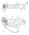
- the stick handle 1 comprises a handle body 3, which is usually made of a plastic material in an injection molding process. From below, the handle body 3 has a recess or a cavity 5, in which the stick, which is formed for example from an aluminum tube, can be inserted and fixed therein.
- the pole grip 1 has a recess 4, which is initially formed to some extent as a blind hole from the side of the hand 6a.
- this Recess 4 which typically has a height in the range of 12-15 mm, and a width of 10-15 mm, the attachment of the hand strap 2 takes place.
- the recess has to the top of the pole grip through an opening in which an eccentric element 11 is mounted.
- It is essentially a plastic cylinder (it is also a cylinder of metal conceivable) which is mounted eccentrically, that is, which is not stored in its axis of gravity but moved to it.
- the axis 12 is in the case of the embodiment according to FIG.
- the eccentric element 11 has a folding handle 13, which is formed either integrally with the eccentric element 11 or molded on or at this this is attached.
- the folding handle points to the front 6b of the handle.
- the folding handle 13 is at least partially recessed in a groove made from above in the pole grip 3 when in the fixing position, as in FIG. 1a ) is shown. Due to the eccentric mounting of the eccentric 11 arise with respect to the axis 12 radii, which are different depending on the rotational position. These different radii are depicted graphically by the arrows a (short radius), b (radius in typical fixation position), and c (large radius).
- the axle 12 is mounted in the pole grip 3, as in particular in FIG. 1b ) is recognizable.
- the lateral surface of the cylinder of the eccentric element can either have a substantially unmodified surface, but it is also possible, in particular in the downwardly directed area where the fixing effect is to be produced, to provide a special surface for increasing the friction with the wrist strap, for example with a roughening, ribs transverse to the loading direction or the like.
- a pin 14 is arranged coaxially with the axis 12. This pin 14 forms the abutment or the counter-pressure surface for the fixation of the loop. Also the pin 14 is, as in FIG. 1b ) is recognizable, embedded in corresponding recesses or holes in the handle body 3. Also the Pin 14 may be provided with a particular surface texture to increase the friction between the pin 14 and the loop. Again, in other words, a roughening or ribs parallel to the axis of the pin 14 or the like are possible.
- a hand strap 2 is screwed or riveted with its attached end 8 in this embodiment.
- the wrist strap is guided around the hand and the other end is then guided into the recess 4 in the region 9 and guided between the pin 14 and the eccentric element 11. Subsequently, the loop is guided downwards around the pin 14 and out of the recess 4 again. As a result, a free end 7 of the wrist strap is formed.
- the loop 2 By pulling on the free end 7, the loop 2 can be shortened with dissolved fastening device in each of these configurations.
- the attachment may be designed to release the loop when attached with a force above a specified force.
- This can be achieved in many different ways, for example by the strap is first struck in its area 8 to a plastic element, which plastic element is fitted in a corresponding recess in the pole grip, and which can be torn out of this recess via material deformation in strong train. Under certain circumstances, the triggering force can even be set via the material of the plastic element become. But there are also more complex mechanisms, which can be adjustable by springs or the like, possible.
- the clamped state is shown, that is the state in which the length of the loop can not be changed.
- the folding handle 13 is sunk forward substantially in the pole grip.
- the folding handle 13 is gripped from the bottom and pulled upwards or turned counterclockwise. In this case, the eccentric 11 rotates about the axis 12. While in the fixing position of the large radius b to the pin 14, now by this rotation, the radius is gradually reduced by the eccentricity until, for example, the position is reached, as indicated by the arrow a is shown. In this position, the folding handle 13 is almost completely upwards, and the gap between the eccentric 11 and the pin 14 is now extended so that the intermediate band is completely released and either by pulling on the free end 7, the hand strap 2 can be shortened , or by pulling on area 9 can be extended.
- the loop After the loop has been changed in length, it can be fixed by folding down the folding handle 13 clockwise (locking direction F) in the new position. Since the radius increases successively during the rotation, the clamping between the eccentric element 11 and the abutment 14 is determined at will according to the force on the folding handle 13.
- the use of the eccentric element 11 thus has, inter alia, the advantage that the force of the determination can be determined adapted to the needs.
- tolerances in the range of the thickness of the guided between eccentric and abutment belt 14 play no major role, as is the case with other attachment mechanisms. Such tolerances can be easily absorbed; and if, for example, a band range between 11 and 14 is pushed, which is somewhat thicker, the lever 13 must be slightly less in the Folded down in a clockwise direction F, and for example, a tape portion of the loop is pushed in between, which is slightly thinner, the lever 13 is simply folded down a little further clockwise.
- a stop for the folding handle 13 is preferably not provided on the pole handle, but rather sufficient clearance is provided in the groove in the handle body 3, so that the folding handle 13 in the case of a thin strip or even in the event of wear of the eccentric element 11 still for Determination can be used.
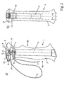
- FIG. 2 an analogous embodiment is shown in which now but the folding handle 13 is not detected in a clockwise direction, but rather in the counterclockwise direction (locking direction F). While in the embodiment according to FIG. 1 In an unusual train on the wrist strap, the eccentric 11 further fixed by the load, this occurs in the embodiment according to FIG. 2 not up. On the contrary, it is even possible under certain circumstances to solve this with a heavy load on the loop band, as a train at the area 9 leads to a torque against the locking direction of rotation F and thus can turn the folding handle. This can be useful, for example, as a safety release.
Claims (9)
- Poignée de bâton (1) comprenant un dispositif de retenue pour la main, notamment pour des bâtons de marche, des bâtons de trekking, des bâtons de ski alpin, des bâtons de ski de fond, des bâtons de marche nordique, comprenant un corps de poignée (3) et un dispositif (11-14) pour la fixation réglable du dispositif de retenue pour la main, notamment sous la forme d'une dragonne (2) ou d'un gant, le dispositif de retenue pour la main présentant, pour la fixation à la poignée de bâton (1), au moins dans une région de fixation du dispositif de retenue pour la main, un moyen de fixation en forme de ruban, de courroie, de sangle ou de bande de tissu, et le dispositif présentant un élément excentré (11) pouvant tourner et/ou pivoter autour d'un axe (12), lequel élément excentré (11) présente, dans la région de fixation, une surface dont le rayon (a, b, c) augmente vers l'axe (12) dans la direction de rotation de fixation (F), de sorte que le moyen de fixation guidé dans la région de fixation entre cette surface de l'élément excentré (11) et une butée fixe (14) soit serré par la rotation ou le pivotement de l'élément excentré (11) dans la direction de rotation de fixation (F) entre l'élément excentré (11) et la butée (14), la surface étant au moins de manière en partie croissante, de manière croissante en continue, nervurée ou étagée, l'axe (12) de l'élément excentré (11) étant disposé de manière essentiellement perpendiculaire à la direction de traction du moyen de fixation et notamment de préférence essentiellement perpendiculaire à l'axe du bâton,
le corps de poignée (3) présentant, depuis le côté de la main (6) à l'extrémité supérieure un logement (4) qui présente, vers le côté supérieur de la poignée pour bâton (1) une ouverture continue, dans laquelle l'élément excentré (11) est supporté avec une goupille axiale (12) guidée des deux côtés dans le corps de poignée (3), la butée (14) étant réalisée dans le logement (4) en forme de nervure ou de goupille disposée sous l'élément excentré (11), qui est supportée des deux côtés dans le corps de poignée (3),
le moyen de fixation étant réalisé sous forme de ruban flexible,
l'élément excentré (11) pouvant être tourné ou pivoté par le biais d'un levier ou d'une poignée rabattable (13) pour serrer le dispositif de retenue pour la main,
et la poignée rabattable (13) étant rabattue vers le haut pour desserrer la fixation du dispositif de retenue pour la main, et étant retournée vers l'avant ou vers l'arrière pour serrer la fixation du dispositif de retenue pour la main, de sorte que le levier soit disposé essentiellement horizontalement dans la position de fixation,
caractérisée en ce que
l'élément excentré (11) est réalisé au moins dans la région de fixation sous forme de cylindre supporté de manière excentrique, et en ce que le ruban flexible est guidé depuis le dispositif de retenue pour la main (2) d'abord entre l'élément excentré (11) et la butée (14), est guidé autour de la butée (14) vers le bas, puis est guidé hors du logement (4), une extrémité libre (7) subsistant, par le biais de laquelle la longueur de la liaison du dispositif de retenue pour la main à la poignée de bâton (1) peut être ajustée. - Poignée de bâton (1) selon la revendication 1, caractérisée en ce que l'axe (12) de l'élément excentré (11) est disposé essentiellement perpendiculaire à l'axe du bâton.
- Poignée de bâton (1) selon la revendication 1 ou 2, caractérisée en ce que le levier ou la poignée rabattable (13) est disposé(e) sur le côté supérieur de la poignée de bâton (1), et de préférence est intégré(e) dans la position de fixation au moins en partie ou notamment presque complètement dans le contour extérieur du corps de poignée (3).
- Poignée de bâton (1) selon l'une quelconque des revendications 1 à 3, caractérisée en ce que la nervure ou la goupille disposée sous l'élément excentré (11) est disposée parallèlement à l'axe de l'élément excentré (11).
- Poignée de bâton (1) selon la revendication 4, caractérisée en ce que le logement (4) présente une hauteur de l'ordre de 12 à 15 mm, et une largeur de 10 à 15 mm.
- Poignée de bâton (1) selon la revendication 4 ou 5, caractérisée en ce que le moyen de fixation est réalisé sous la forme d'un ruban flexible, en forme de ruban tissé, de préférence en plastique.
- Poignée de bâton (1) selon la revendication 6, caractérisée en ce que le dispositif de retenue pour la main est une boucle, dont l'extrémité supérieure (8) est fixée de manière fixe ou arrachable dans le sens d'une fixation de sécurité sur le corps de poignée, notamment de préférence sur le plafond inférieur du logement, laquelle est guidée autour de la main et dont une région (9) est guidée à l'intérieur du logement de la poignée de bâton (11).
- Poignée de bâton (1) selon la revendication 6, caractérisée en ce que la poignée rabattable (13) est rabattue vers le haut pour desserrer la fixation du dispositif de retenue pour la main, et est retournée vers l'arrière pour serrer la fixation du dispositif de retenue pour la main, et en ce que le dispositif de retenue pour la main est un boucle dont l'extrémité supérieure (8) est fixée à la poignée rabattable (13), laquelle est guidée autour de la main et dont une région (9) est guidée à l'intérieur du logement de la poignée de bâton (11).
- Poignée de bâton (1) selon la revendication 6, caractérisée en ce que le dispositif de retenue pour la main est un gant ou un dispositif de boucle pouvant être fixé sur la main, qui dispose, essentiellement entre le pouce et l'index, d'un ruban qui est guidé dans le logement de la poignée de bâton (11).
Applications Claiming Priority (2)
| Application Number | Priority Date | Filing Date | Title |
|---|---|---|---|
| CH1992005 | 2005-02-08 | ||
| PCT/CH2006/000069 WO2006084403A1 (fr) | 2005-02-08 | 2006-02-06 | Poignee de baton |
Publications (2)
| Publication Number | Publication Date |
|---|---|
| EP1848298A1 EP1848298A1 (fr) | 2007-10-31 |
| EP1848298B1 true EP1848298B1 (fr) | 2011-09-14 |
Family
ID=34974794
Family Applications (1)
| Application Number | Title | Priority Date | Filing Date |
|---|---|---|---|
| EP06701539A Active EP1848298B1 (fr) | 2005-02-08 | 2006-02-06 | Poignee de baton |
Country Status (8)
| Country | Link |
|---|---|
| US (1) | US7621564B2 (fr) |
| EP (1) | EP1848298B1 (fr) |
| JP (1) | JP4920601B2 (fr) |
| CN (1) | CN101115411B (fr) |
| AT (1) | ATE524086T1 (fr) |
| CA (1) | CA2592502C (fr) |
| NO (1) | NO339317B1 (fr) |
| WO (1) | WO2006084403A1 (fr) |
Cited By (1)
| Publication number | Priority date | Publication date | Assignee | Title |
|---|---|---|---|---|
| DE102017119404B3 (de) | 2017-08-24 | 2018-05-09 | Dexin Corp. | Ringförmiger Kopfhörer |
Families Citing this family (15)
| Publication number | Priority date | Publication date | Assignee | Title |
|---|---|---|---|---|
| CN100586517C (zh) * | 2004-12-10 | 2010-02-03 | 雷克体育公众有限公司 | 具有可调手腕带的杖柄 |
| US8579329B2 (en) * | 2004-12-23 | 2013-11-12 | Lekisport Ag | Pole grip |
| CH699566A2 (de) | 2008-09-25 | 2010-03-31 | Lekisport Ag | Stockgriff. |
| DE202008012802U1 (de) | 2008-09-26 | 2009-01-08 | Lekisport Ag | Stockgriff |
| EP2547228B1 (fr) * | 2010-03-19 | 2019-04-17 | Lekisport AG | Poignée de bâton |
| WO2011157555A1 (fr) | 2010-06-14 | 2011-12-22 | Lekisport Ag | Dragonne pour poignée de bâton |
| CH704813B1 (de) * | 2011-04-05 | 2015-09-15 | Lekisport Ag | Handschlaufe für einen Stockgriff. |
| AT12782U1 (de) * | 2011-12-01 | 2012-11-15 | Komperdell Sportartikel Ges M B H | Stock mit schlaufe |
| EP2849603B1 (fr) * | 2012-05-18 | 2018-05-23 | Lekisport AG | Poignée de bâton dotée d'une boucle guidée |
| WO2014066516A1 (fr) | 2012-10-23 | 2014-05-01 | New York University | Objet portable renvoyant des informations de capteurs somatiques |
| KR101597674B1 (ko) * | 2014-07-01 | 2016-02-25 | 김상순 | 지팡이 |
| FR3032333B1 (fr) | 2015-02-09 | 2018-03-30 | Frederic Dubois | Poignee de baton pivotante |
| EP3595483B1 (fr) * | 2017-03-15 | 2022-04-20 | Lekisport AG | Poignée de bâton |
| CN116033947A (zh) | 2020-07-14 | 2023-04-28 | 雷克体育公众有限公司 | 轻质结构手柄头 |
| DE202022001480U1 (de) | 2022-06-30 | 2023-05-31 | Herbert Eberlein | Gehstock zur paarweisen Verwendung |
Citations (1)
| Publication number | Priority date | Publication date | Assignee | Title |
|---|---|---|---|---|
| DE29520269U1 (de) * | 1995-12-21 | 1996-03-07 | Lenhart Klaus | Stockgriff |
Family Cites Families (26)
| Publication number | Priority date | Publication date | Assignee | Title |
|---|---|---|---|---|
| US3085814A (en) * | 1960-12-02 | 1963-04-16 | Edward L Scott | Handle construction for ski poles |
| US3113786A (en) * | 1962-09-28 | 1963-12-10 | Phillipson Rod & Tackle Co | Ski pole wrist straps |
| US3335585A (en) * | 1965-03-15 | 1967-08-15 | Bruce D Stratton | Ski pole with lock |
| US3560014A (en) * | 1967-08-17 | 1971-02-02 | Franz Xaver Bruckl | Ski pole provided with hand loop |
| US3561782A (en) * | 1969-01-23 | 1971-02-09 | Donald P Tyrack | Ski pole construction with liquid reservoir |
| JPS4926936Y1 (fr) * | 1971-05-27 | 1974-07-22 | ||
| US3810647A (en) * | 1972-07-20 | 1974-05-14 | E Martchenke | Ski pole with camera mounting means |
| JPS5718734B2 (fr) * | 1973-11-27 | 1982-04-19 | ||
| FI63679C (fi) * | 1977-12-30 | 1983-08-10 | Exel Oy | Anordning foer reglering av laengden hos en skidstavs handledsrem |
| FI59729C (fi) * | 1978-02-20 | 1981-10-12 | Exel Oy | En knoppformig oevre del foer ett skidstavshandtag |
| FR2569350B1 (fr) * | 1984-08-21 | 1987-01-23 | Kerma | Poignee de baton de ski |
| FR2573318A1 (fr) | 1984-11-16 | 1986-05-23 | Bibollet Jean Claude | Baton de ski muni d'un dispositif de reglage en longueur de dragonne |
| JPH031426U (fr) * | 1989-05-23 | 1991-01-09 | ||
| JPH08103529A (ja) * | 1994-10-05 | 1996-04-23 | Sadao Naito | スキーストック用グリップ |
| DE19636852C1 (de) * | 1996-09-11 | 1998-02-12 | Klaus Lenhart | Stockgriff mit Handschlaufe |
| DE19751978C2 (de) * | 1997-11-25 | 2001-07-05 | Klaus Lenhart | Handschuh mit integrierter Handschlaufe für Stöcke |
| DE59903786D1 (de) * | 1998-11-18 | 2003-01-23 | Klaus Lenhart | Stock wie skistock, wanderstock oder dergleichen |
| DE29904591U1 (de) * | 1999-03-15 | 2000-08-24 | Lenhart Klaus | Stockgriff mit Handschlaufe |
| DE29906612U1 (de) * | 1999-04-14 | 2000-08-24 | Lenhart Klaus | Stockgriff mit einstellbarer Handschlaufe |
| FR2792539B1 (fr) * | 1999-04-23 | 2001-06-01 | Rossignol Sa | Poignee de baton de ski equipee d'une dragonne de securite |
| IT246739Y1 (it) | 1999-05-18 | 2002-04-10 | Pronzati Giuseppe Gipron Spa | Impugnatura per bastone da sci trekking e simili con lacciolo regolabi-le |
| US6439610B1 (en) * | 1999-05-18 | 2002-08-27 | Gipron Giuseppe Pronzati S.P.A. | Stick handle for ski, trekking and the like with adjustable wrist strap |
| ITVI20000003U1 (it) | 2000-01-18 | 2001-07-18 | Zaltron Renato | Struttura di impugnatura con passamano particolarment per bastoncini da passeggio trekking sci alpino e fondo |
| US6851437B1 (en) * | 2000-05-19 | 2005-02-08 | Klaus Lenhart | Cane handle with adjustable supporting loop |
| DE20114396U1 (de) | 2001-08-31 | 2003-01-16 | Lenhart Klaus | Stockgriff mit einstellbarer Handschlaufe |
| DE20219461U1 (de) * | 2002-12-10 | 2004-04-22 | Lenhart, Klaus | Stockgriff mit Handschlaufe |
-
2006
- 2006-02-06 EP EP06701539A patent/EP1848298B1/fr active Active
- 2006-02-06 CA CA2592502A patent/CA2592502C/fr active Active
- 2006-02-06 US US11/794,344 patent/US7621564B2/en active Active
- 2006-02-06 AT AT06701539T patent/ATE524086T1/de active
- 2006-02-06 CN CN2006800041378A patent/CN101115411B/zh active Active
- 2006-02-06 WO PCT/CH2006/000069 patent/WO2006084403A1/fr active Application Filing
- 2006-02-06 JP JP2007553435A patent/JP4920601B2/ja active Active
-
2007
- 2007-06-11 NO NO20072949A patent/NO339317B1/no unknown
Patent Citations (1)
| Publication number | Priority date | Publication date | Assignee | Title |
|---|---|---|---|---|
| DE29520269U1 (de) * | 1995-12-21 | 1996-03-07 | Lenhart Klaus | Stockgriff |
Cited By (1)
| Publication number | Priority date | Publication date | Assignee | Title |
|---|---|---|---|---|
| DE102017119404B3 (de) | 2017-08-24 | 2018-05-09 | Dexin Corp. | Ringförmiger Kopfhörer |
Also Published As
| Publication number | Publication date |
|---|---|
| CN101115411B (zh) | 2010-09-08 |
| JP4920601B2 (ja) | 2012-04-18 |
| NO20072949L (no) | 2007-10-05 |
| US7621564B2 (en) | 2009-11-24 |
| NO339317B1 (no) | 2016-11-28 |
| ATE524086T1 (de) | 2011-09-15 |
| CN101115411A (zh) | 2008-01-30 |
| US20080036191A1 (en) | 2008-02-14 |
| JP2008529566A (ja) | 2008-08-07 |
| CA2592502A1 (fr) | 2006-08-17 |
| WO2006084403A1 (fr) | 2006-08-17 |
| CA2592502C (fr) | 2013-04-02 |
| EP1848298A1 (fr) | 2007-10-31 |
Similar Documents
| Publication | Publication Date | Title |
|---|---|---|
| EP1848298B1 (fr) | Poignee de baton | |
| EP1827623B1 (fr) | Poignee de baton | |
| DE19829899B4 (de) | Reibschlüssige Gurteinstellvorrichtung | |
| EP0528252B1 (fr) | Pince avec deux bras | |
| EP2762209B1 (fr) | Talonnière avec levier auxiliaire | |
| EP1819406B1 (fr) | Poignee de baton comportant une dragonne reglable | |
| DE4143410C2 (de) | Sicherheitsbindung | |
| DE2821140C2 (de) | Schließe für Riemen, Gurte o.dgl. | |
| EP1036579A2 (fr) | Poignée de bâton avec dragonne | |
| EP1474212B1 (fr) | Poignee de canne avec dragonne | |
| EP3595483B1 (fr) | Poignée de bâton | |
| EP3476446B1 (fr) | Fixation pourvu d'élément de sécurité pour les freins de ski | |
| DE202009004370U1 (de) | Längenverstellbarer Stock und Klemmvorrichtung dafür | |
| EP1810589B1 (fr) | Poignée de bâton | |
| DE4142391A1 (de) | Skistiefel | |
| DE2838903C2 (de) | Sicherheitsskibindung | |
| DE102005044132A1 (de) | Befestigungssystem mit Spannverschluss zum Befestigen eines Gepäckstücks auf einem Fahrradgepäckträger | |
| EP3332843A1 (fr) | Unité de talon pour une fixation de planche de glisse dotée d'un systeme de frein | |
| DE1528040A1 (de) | Saege | |
| DE2406762C3 (de) | Auslöse-Skibindung | |
| DE2407464B2 (de) | Klemmvorrichtung für einen teleskopartig längenverstellbaren Skistock | |
| DE3040766A1 (de) | Skibremse | |
| AT502887B1 (de) | Baugruppe für die einstellung einer skibindung und deren fixierung in einer ausgewählten position | |
| EP1158184B1 (fr) | Dispositif de fixation d'un objet, en particulier une lampe | |
| AT509610B1 (de) | Verstellvorrichtung, insbesondere längenverstellvorrichtung |
Legal Events
| Date | Code | Title | Description |
|---|---|---|---|
| PUAI | Public reference made under article 153(3) epc to a published international application that has entered the european phase |
Free format text: ORIGINAL CODE: 0009012 |
|
| 17P | Request for examination filed |
Effective date: 20070816 |
|
| AK | Designated contracting states |
Kind code of ref document: A1 Designated state(s): AT BE BG CH CY CZ DE DK EE ES FI FR GB GR HU IE IS IT LI LT LU LV MC NL PL PT RO SE SI SK TR |
|
| DAX | Request for extension of the european patent (deleted) | ||
| 17Q | First examination report despatched |
Effective date: 20090525 |
|
| GRAP | Despatch of communication of intention to grant a patent |
Free format text: ORIGINAL CODE: EPIDOSNIGR1 |
|
| GRAS | Grant fee paid |
Free format text: ORIGINAL CODE: EPIDOSNIGR3 |
|
| GRAA | (expected) grant |
Free format text: ORIGINAL CODE: 0009210 |
|
| AK | Designated contracting states |
Kind code of ref document: B1 Designated state(s): AT BE BG CH CY CZ DE DK EE ES FI FR GB GR HU IE IS IT LI LT LU LV MC NL PL PT RO SE SI SK TR |
|
| REG | Reference to a national code |
Ref country code: GB Ref legal event code: FG4D Free format text: NOT ENGLISH |
|
| REG | Reference to a national code |
Ref country code: CH Ref legal event code: EP |
|
| REG | Reference to a national code |
Ref country code: IE Ref legal event code: FG4D Free format text: LANGUAGE OF EP DOCUMENT: GERMAN |
|
| REG | Reference to a national code |
Ref country code: CH Ref legal event code: NV Representative=s name: ISLER & PEDRAZZINI AG |
|
| REG | Reference to a national code |
Ref country code: NL Ref legal event code: T3 |
|
| REG | Reference to a national code |
Ref country code: DE Ref legal event code: R096 Ref document number: 502006010165 Country of ref document: DE Effective date: 20111201 |
|
| REG | Reference to a national code |
Ref country code: SE Ref legal event code: TRGR |
|
| PG25 | Lapsed in a contracting state [announced via postgrant information from national office to epo] |
Ref country code: LT Free format text: LAPSE BECAUSE OF FAILURE TO SUBMIT A TRANSLATION OF THE DESCRIPTION OR TO PAY THE FEE WITHIN THE PRESCRIBED TIME-LIMIT Effective date: 20110914 |
|
| LTIE | Lt: invalidation of european patent or patent extension |
Effective date: 20110914 |
|
| PG25 | Lapsed in a contracting state [announced via postgrant information from national office to epo] |
Ref country code: LV Free format text: LAPSE BECAUSE OF FAILURE TO SUBMIT A TRANSLATION OF THE DESCRIPTION OR TO PAY THE FEE WITHIN THE PRESCRIBED TIME-LIMIT Effective date: 20110914 Ref country code: SI Free format text: LAPSE BECAUSE OF FAILURE TO SUBMIT A TRANSLATION OF THE DESCRIPTION OR TO PAY THE FEE WITHIN THE PRESCRIBED TIME-LIMIT Effective date: 20110914 Ref country code: CY Free format text: LAPSE BECAUSE OF FAILURE TO SUBMIT A TRANSLATION OF THE DESCRIPTION OR TO PAY THE FEE WITHIN THE PRESCRIBED TIME-LIMIT Effective date: 20110914 Ref country code: GR Free format text: LAPSE BECAUSE OF FAILURE TO SUBMIT A TRANSLATION OF THE DESCRIPTION OR TO PAY THE FEE WITHIN THE PRESCRIBED TIME-LIMIT Effective date: 20111215 |
|
| REG | Reference to a national code |
Ref country code: IE Ref legal event code: FD4D |
|
| PG25 | Lapsed in a contracting state [announced via postgrant information from national office to epo] |
Ref country code: CZ Free format text: LAPSE BECAUSE OF FAILURE TO SUBMIT A TRANSLATION OF THE DESCRIPTION OR TO PAY THE FEE WITHIN THE PRESCRIBED TIME-LIMIT Effective date: 20110914 Ref country code: IS Free format text: LAPSE BECAUSE OF FAILURE TO SUBMIT A TRANSLATION OF THE DESCRIPTION OR TO PAY THE FEE WITHIN THE PRESCRIBED TIME-LIMIT Effective date: 20120114 Ref country code: IE Free format text: LAPSE BECAUSE OF FAILURE TO SUBMIT A TRANSLATION OF THE DESCRIPTION OR TO PAY THE FEE WITHIN THE PRESCRIBED TIME-LIMIT Effective date: 20110914 Ref country code: SK Free format text: LAPSE BECAUSE OF FAILURE TO SUBMIT A TRANSLATION OF THE DESCRIPTION OR TO PAY THE FEE WITHIN THE PRESCRIBED TIME-LIMIT Effective date: 20110914 |
|
| PG25 | Lapsed in a contracting state [announced via postgrant information from national office to epo] |
Ref country code: PL Free format text: LAPSE BECAUSE OF FAILURE TO SUBMIT A TRANSLATION OF THE DESCRIPTION OR TO PAY THE FEE WITHIN THE PRESCRIBED TIME-LIMIT Effective date: 20110914 Ref country code: RO Free format text: LAPSE BECAUSE OF FAILURE TO SUBMIT A TRANSLATION OF THE DESCRIPTION OR TO PAY THE FEE WITHIN THE PRESCRIBED TIME-LIMIT Effective date: 20110914 Ref country code: PT Free format text: LAPSE BECAUSE OF FAILURE TO SUBMIT A TRANSLATION OF THE DESCRIPTION OR TO PAY THE FEE WITHIN THE PRESCRIBED TIME-LIMIT Effective date: 20120116 Ref country code: EE Free format text: LAPSE BECAUSE OF FAILURE TO SUBMIT A TRANSLATION OF THE DESCRIPTION OR TO PAY THE FEE WITHIN THE PRESCRIBED TIME-LIMIT Effective date: 20110914 |
|
| PLBE | No opposition filed within time limit |
Free format text: ORIGINAL CODE: 0009261 |
|
| STAA | Information on the status of an ep patent application or granted ep patent |
Free format text: STATUS: NO OPPOSITION FILED WITHIN TIME LIMIT |
|
| PG25 | Lapsed in a contracting state [announced via postgrant information from national office to epo] |
Ref country code: DK Free format text: LAPSE BECAUSE OF FAILURE TO SUBMIT A TRANSLATION OF THE DESCRIPTION OR TO PAY THE FEE WITHIN THE PRESCRIBED TIME-LIMIT Effective date: 20110914 |
|
| 26N | No opposition filed |
Effective date: 20120615 |
|
| BERE | Be: lapsed |
Owner name: LEKISPORT A.G. Effective date: 20120228 |
|
| PG25 | Lapsed in a contracting state [announced via postgrant information from national office to epo] |
Ref country code: MC Free format text: LAPSE BECAUSE OF NON-PAYMENT OF DUE FEES Effective date: 20120229 |
|
| REG | Reference to a national code |
Ref country code: DE Ref legal event code: R097 Ref document number: 502006010165 Country of ref document: DE Effective date: 20120615 |
|
| PG25 | Lapsed in a contracting state [announced via postgrant information from national office to epo] |
Ref country code: BE Free format text: LAPSE BECAUSE OF NON-PAYMENT OF DUE FEES Effective date: 20120228 |
|
| PG25 | Lapsed in a contracting state [announced via postgrant information from national office to epo] |
Ref country code: ES Free format text: LAPSE BECAUSE OF FAILURE TO SUBMIT A TRANSLATION OF THE DESCRIPTION OR TO PAY THE FEE WITHIN THE PRESCRIBED TIME-LIMIT Effective date: 20111225 |
|
| PG25 | Lapsed in a contracting state [announced via postgrant information from national office to epo] |
Ref country code: BG Free format text: LAPSE BECAUSE OF FAILURE TO SUBMIT A TRANSLATION OF THE DESCRIPTION OR TO PAY THE FEE WITHIN THE PRESCRIBED TIME-LIMIT Effective date: 20111214 |
|
| PG25 | Lapsed in a contracting state [announced via postgrant information from national office to epo] |
Ref country code: TR Free format text: LAPSE BECAUSE OF FAILURE TO SUBMIT A TRANSLATION OF THE DESCRIPTION OR TO PAY THE FEE WITHIN THE PRESCRIBED TIME-LIMIT Effective date: 20110914 |
|
| PG25 | Lapsed in a contracting state [announced via postgrant information from national office to epo] |
Ref country code: LU Free format text: LAPSE BECAUSE OF NON-PAYMENT OF DUE FEES Effective date: 20120206 |
|
| PG25 | Lapsed in a contracting state [announced via postgrant information from national office to epo] |
Ref country code: HU Free format text: LAPSE BECAUSE OF FAILURE TO SUBMIT A TRANSLATION OF THE DESCRIPTION OR TO PAY THE FEE WITHIN THE PRESCRIBED TIME-LIMIT Effective date: 20060206 |
|
| REG | Reference to a national code |
Ref country code: FR Ref legal event code: PLFP Year of fee payment: 11 |
|
| REG | Reference to a national code |
Ref country code: FR Ref legal event code: PLFP Year of fee payment: 12 |
|
| REG | Reference to a national code |
Ref country code: FR Ref legal event code: PLFP Year of fee payment: 13 |
|
| PGFP | Annual fee paid to national office [announced via postgrant information from national office to epo] |
Ref country code: FR Payment date: 20230220 Year of fee payment: 18 Ref country code: FI Payment date: 20230224 Year of fee payment: 18 Ref country code: CH Payment date: 20230307 Year of fee payment: 18 Ref country code: AT Payment date: 20230217 Year of fee payment: 18 |
|
| PGFP | Annual fee paid to national office [announced via postgrant information from national office to epo] |
Ref country code: SE Payment date: 20230216 Year of fee payment: 18 Ref country code: IT Payment date: 20230217 Year of fee payment: 18 |
|
| P01 | Opt-out of the competence of the unified patent court (upc) registered |
Effective date: 20230516 |
|
| PGFP | Annual fee paid to national office [announced via postgrant information from national office to epo] |
Ref country code: NL Payment date: 20240219 Year of fee payment: 19 |
|
| PGFP | Annual fee paid to national office [announced via postgrant information from national office to epo] |
Ref country code: AT Payment date: 20240220 Year of fee payment: 19 |
|
| PGFP | Annual fee paid to national office [announced via postgrant information from national office to epo] |
Ref country code: FI Payment date: 20240219 Year of fee payment: 19 Ref country code: DE Payment date: 20240219 Year of fee payment: 19 Ref country code: CH Payment date: 20240301 Year of fee payment: 19 Ref country code: GB Payment date: 20240219 Year of fee payment: 19 |