EP1837190B1 - Image forming apparatus and image forming method - Google Patents
Image forming apparatus and image forming method Download PDFInfo
- Publication number
- EP1837190B1 EP1837190B1 EP07013730A EP07013730A EP1837190B1 EP 1837190 B1 EP1837190 B1 EP 1837190B1 EP 07013730 A EP07013730 A EP 07013730A EP 07013730 A EP07013730 A EP 07013730A EP 1837190 B1 EP1837190 B1 EP 1837190B1
- Authority
- EP
- European Patent Office
- Prior art keywords
- image
- fixing
- fixing device
- recording material
- image forming
- Prior art date
- Legal status (The legal status is an assumption and is not a legal conclusion. Google has not performed a legal analysis and makes no representation as to the accuracy of the status listed.)
- Expired - Lifetime
Links
Images





Classifications
-
- G—PHYSICS
- G03—PHOTOGRAPHY; CINEMATOGRAPHY; ANALOGOUS TECHNIQUES USING WAVES OTHER THAN OPTICAL WAVES; ELECTROGRAPHY; HOLOGRAPHY
- G03G—ELECTROGRAPHY; ELECTROPHOTOGRAPHY; MAGNETOGRAPHY
- G03G15/00—Apparatus for electrographic processes using a charge pattern
- G03G15/20—Apparatus for electrographic processes using a charge pattern for fixing, e.g. by using heat
- G03G15/2003—Apparatus for electrographic processes using a charge pattern for fixing, e.g. by using heat using heat
- G03G15/2014—Apparatus for electrographic processes using a charge pattern for fixing, e.g. by using heat using heat using contact heat
- G03G15/2039—Apparatus for electrographic processes using a charge pattern for fixing, e.g. by using heat using heat using contact heat with means for controlling the fixing temperature
- G03G15/2046—Apparatus for electrographic processes using a charge pattern for fixing, e.g. by using heat using heat using contact heat with means for controlling the fixing temperature specially for the influence of heat loss, e.g. due to the contact with the copy material or other roller
-
- G—PHYSICS
- G03—PHOTOGRAPHY; CINEMATOGRAPHY; ANALOGOUS TECHNIQUES USING WAVES OTHER THAN OPTICAL WAVES; ELECTROGRAPHY; HOLOGRAPHY
- G03G—ELECTROGRAPHY; ELECTROPHOTOGRAPHY; MAGNETOGRAPHY
- G03G15/00—Apparatus for electrographic processes using a charge pattern
- G03G15/50—Machine control of apparatus for electrographic processes using a charge pattern, e.g. regulating differents parts of the machine, multimode copiers, microprocessor control
- G03G15/5004—Power supply control, e.g. power-saving mode, automatic power turn-off
-
- G—PHYSICS
- G03—PHOTOGRAPHY; CINEMATOGRAPHY; ANALOGOUS TECHNIQUES USING WAVES OTHER THAN OPTICAL WAVES; ELECTROGRAPHY; HOLOGRAPHY
- G03G—ELECTROGRAPHY; ELECTROPHOTOGRAPHY; MAGNETOGRAPHY
- G03G2215/00—Apparatus for electrophotographic processes
- G03G2215/00362—Apparatus for electrophotographic processes relating to the copy medium handling
- G03G2215/00535—Stable handling of copy medium
- G03G2215/00717—Detection of physical properties
- G03G2215/00742—Detection of physical properties of sheet weight
-
- G—PHYSICS
- G03—PHOTOGRAPHY; CINEMATOGRAPHY; ANALOGOUS TECHNIQUES USING WAVES OTHER THAN OPTICAL WAVES; ELECTROGRAPHY; HOLOGRAPHY
- G03G—ELECTROGRAPHY; ELECTROPHOTOGRAPHY; MAGNETOGRAPHY
- G03G2215/00—Apparatus for electrophotographic processes
- G03G2215/00362—Apparatus for electrophotographic processes relating to the copy medium handling
- G03G2215/00789—Adding properties or qualities to the copy medium
- G03G2215/00805—Gloss adding or lowering device
- G03G2215/0081—Gloss level being selectable
-
- G—PHYSICS
- G03—PHOTOGRAPHY; CINEMATOGRAPHY; ANALOGOUS TECHNIQUES USING WAVES OTHER THAN OPTICAL WAVES; ELECTROGRAPHY; HOLOGRAPHY
- G03G—ELECTROGRAPHY; ELECTROPHOTOGRAPHY; MAGNETOGRAPHY
- G03G2215/00—Apparatus for electrophotographic processes
- G03G2215/00362—Apparatus for electrophotographic processes relating to the copy medium handling
- G03G2215/00919—Special copy medium handling apparatus
- G03G2215/00924—Special copy medium handling apparatus two or more parallel feed paths
-
- G—PHYSICS
- G03—PHOTOGRAPHY; CINEMATOGRAPHY; ANALOGOUS TECHNIQUES USING WAVES OTHER THAN OPTICAL WAVES; ELECTROGRAPHY; HOLOGRAPHY
- G03G—ELECTROGRAPHY; ELECTROPHOTOGRAPHY; MAGNETOGRAPHY
- G03G2215/00—Apparatus for electrophotographic processes
- G03G2215/20—Details of the fixing device or porcess
- G03G2215/2003—Structural features of the fixing device
- G03G2215/2006—Plurality of separate fixing areas
Definitions
- the present invention relates to an image forming apparatus such as a copying machine, a printer, a facsimile machine or the like wherein an image is formed through an electrophotographic process or an electrostatic recording process, and also to an image forming method therefor.
- a number of types of full-color image forming apparatus such as a printer, a copying machine or the like using an electrophotographic process.
- the full-color image forming apparatus is required to have the capability of forming an image on various recording materials and to have the capability of high speed image formation with high image quality.
- an image fixing device is desirably capable of applying optimum amount of heat to the recording material and to the toner. By such application of heat, the fixing strength is assured, and a preferable image glossiness is provided.
- the fixing temperature is set high, or the fixing speed is lowered to increase the fixing time period.
- Japanese Laid-open Patent Application 2002-49258 and Japanese Laid-open Patent Application 2000-221821 propose image forming apparatus wherein the use is made with a plurality of fixing devices to apply heat to the toner and to the recording material a plurality of times corresponding to the number of the fixing devices so that various recording materials are usable without lowering the fixing speed, that is, at a high speed.
- the number of the fixing devices to be used is changed depending on the types of the recording material.
- said other fixing device or devices are in the heated state despite the fact that they are not used, the device is thermally deteriorated gradually with the result of shortening of the service life.
- US 2002/0191992 A discloses an image forming apparatus provided with a primary and a secondary fixing device, said apparatus being operable in a mode in which only the primary fixing device is used to fix the image and a mode in which both fixing devices are used to fix the image.
- JP 05 323710 A discloses an image forming device having a single fixing device, where the target temperature is reduced in the stand-by state.
- FIG. 11 there is shown a schematic sectional view of a major part of an image forming apparatus employing an electrophotographic -process.
- the image forming apparatus comprises four image forming stations Pa, Pb, Pc, Pd (image forming means) as shown in this Figure.
- the image forming stations Pa, Pb, Pc, Pd function to form magenta, cyan, yellow and black images, respectively, and they have respective photosensitive drums 1a, 1b, 1c, 1d (image bearing members) rotatable in the direction of an arrow in Figure 4 .
- chargers 12a, 12b, 12c, 12d developing devices 2a, 2b, 2c, 2d, and cleaner 4a, 4b, 4c, 4d, as process means, in the order named in the direction of rotation of the associated photosensitive drums 1a, 1b, 1c, 1d.
- the transfer stations 3 include chargers 3a, 3b, 3c, 3d, and a common transfer belt 31 (recording material feeding means) is provided.
- Toner images are formed on the respective photosensitive drums in timed relation with a recording material P supplied from an unshown sheet feeding cassette and carried on the transfer belt 31.
- the toner images of respective colors are superimposedly transferred onto the recording material P on the transfer belt 31.
- the recording material P is separated from the transfer belt 31 and is fed to a fixing device A.
- the unfixed toner image transferred onto the recording material P is fixed on the recording material P by the fixing device A and is discharged to an outside of the apparatus.
- the recording material P are sheet materials such as plain paper, coated paper, transparent film or the like, on which the image is formed.
- FIG. 1 there is shown a schematic view of the fixing device A (image heating apparatus) used in the image forming apparatus.
- the fixing device A comprises a frame 9, in which a fixing device I and a fixing device II are provided as image heating means.
- Fixing device II is disposed at a position downstream of the fixing device I with respect to the feeding direction of the recording material P.
- the description will first be made as to the fixing device I (first image heating means) which is disposed upstream.
- the upstream fixing device I has a fixing roller 32a (heating element) and a pressing roller 32c (pressing member).
- the fixing roller 32a is contacted to an unfixed toner image T on the recording material P to fix the image on the recording material P.
- the fixing roller 32a includes a cylindrical core metal of aluminum having an outer diameter of 46 mm and a thickness of 3 mm, a silicone rubber layer of 2 mm thick (JIS-A 10° in hardness) on the outer periphery of the core metal, and a surface parting layer of 50 ⁇ m thick (PFA tube).
- the outer diameter of the fixing roller 32a constituted by these components is approx. 50 mm.
- the pressing roller 32c may have a similar structure as the fixing roller 32a.
- the relative position between the fixing roller 32a and the pressing roller 32c may be a pressing position (fixing position) and a separate position (stand-by position).
- Figure 1 shows a separate position. In the pressing position, the roller are pressed against each other with a total pressure of 100 kgf (980N) by a known pressing method using a spring or the like not shown.
- the press-contact portion (nip) between the fixing roller 32a and the pressing roller 32c has a width of approx. 10 mm (nip width) measured in the feeding direction of the sheet.
- a fixing speed of the fixing device I is 200 mm/sec, and therefore, 40 sheets of A4 size can be fixed per 1 min.
- the time required for shifting from the separate position to the pressing position or shifting from the pressing position to the separate position is 0. 5 sec. The details of the operation will be described hereinafter.
- a halogen heater 213 (thermister) of 700W.
- a temperature sensor 202 (thermister) as a temperature detecting means is contacted to the surface of the fixing roller 32a to sense the surface temperature of the fixing roller 32a.
- the surface temperature of the fixing roller 32a is controlled by rendering on and off the electric power supply to the halogen heater 213 by a controller 200 ( Figure 2 ) in response to the output signal of the temperature sensor 202 (thermister) so as to maintain a predetermined target temperature.
- the recording material P fixed in the nip is fed to the downstream side of the fixing device I by sheet discharging rollers-40a.
- the downstream fixing device II includes a fixing roller 32b as a heating element and a pressing roller 32d as a pressing member.
- the fixing roller 32 b includes a cylindrical core metal of aluminum having an outer diameter of 46 mm and a thickness of 3 mm, a silicone rubber layer of 2 mm thick (JIS-A 10° in hardness) on the outer periphery of the core metal, and a surface parting layer of 50 _Em thick (PFA tube).
- the outer diameter of the fixing roller 32b constituted by these components is approx. 50 mm.
- This fixing roller is the same as the fixing roller 32a of the upstream fixing device I in the embodiment, but may be a different one.
- the pressing roller 32d may be the same as the fixing roller 32b.
- the relative position between the fixing roller 32 b and the pressing roller 32 d may be a pressing position (fixing position) and a separate position (stand-by position).
- Figure 1 shows a separate position.
- the roller In the pressing position, the roller are pressed against each other with a total pressure of 100 kgf (980N) by a known pressing method using a spring or the like not shown.
- the press-contact portion (nip) between the fixing roller 32 b and the pressing roller 32 d has a width of approx. 10 mm (nip width) measured in the feeding direction of the sheet.
- a fixing speed of the fixing device II is 200 mm/sec, and therefore, 40 sheets of A4 size can be fixed per 1 min.
- the time required for shifting from the separate position to the pressing position or shifting from the pressing position to the separate position is 0. 5 sec. The details of the operation will be described hereinafter.
- a halogen heater 214 of 500 W.
- a temperature sensor 204 (thermister) as a temperature detecting means is contacted to the surface of the fixing roller 32 b to sense the surface temperature of the fixing roller 32 b.
- the surface temperature of the fixing roller 32 b is controlled by rendering on and off the electric power supply to the halogen heater 214 by a controller 200 ( Figure 2 ) in response to the output signal of the temperature sensor 204 (thermister) so as to maintain a predetermined target temperature.
- the recording material P fixed in the nip is fed and discharged to the outside of the apparatus.
- the distance between the feeding roller 40a of the fixing device I and the feeding roller 40b of the fixing device II is 140 mm which is shorter than a minimum (in the feeding direction) processible recording material, such as a post card, for example. Therefore, even if the fixing roller 32b and the pressing roller 32d of the fixing device II are in the separate position, the recording material P can be fed to the downstream by the feeding roller 40a and the feeding roller 40b after the recording material P is subjected to the fixing device I.
- FIG. 2 is a block diagram illustrating an example of a control system of the image forming apparatus according to an embodiment of the present invention.
- designated by reference numeral 200 is a controller which comprises a CPU200a, a ROM 200b, a RAM 200c and so on, and it controls the entirety of the copying sequence in accordance with the program stored in the ROM 200b.
- the operating portion 219 includes a display portion for manual selection of a copying mode, copy start or the like.
- the operating portion 219 has a key input portion which includes a copying mode setting key, a copy number setting key, a copying operation start key, a copying operation stop key, a fixing electric power saving key (energy saving key) for adjusting the electric power supply amount to the fixing roller 32b, a reset key for resetting the operation mode to the standard mode, and the like ; and a display portion including a LED lamps and/or liquid crystal display for displaying the set states of operation mode or the like.
- a key input portion which includes a copying mode setting key, a copy number setting key, a copying operation start key, a copying operation stop key, a fixing electric power saving key (energy saving key) for adjusting the electric power supply amount to the fixing roller 32b, a reset key for resetting the operation mode to the standard mode, and the like ; and a display portion including a LED lamps and/or liquid crystal display for displaying the set states of operation mode or the like.
- the thermister 202 detects the surface temperature of the fixing roller 32a, and the detected temperature is converted by an A/D converter 201, and the converted data is inputted to the controller 200.
- the controller 200 controls the heater to keep the surface temperature of the fixing device 32a at a predetermined level using the detected value of the thermister 202.
- the thermister 204 detects the surface temperature of the fixing roller 32b, which is A/D-converted by an A/D converter 203 and then is inputted to the controller 200.
- the controller 200 controls so as to provide a predetermined surface temperature of the fixing roller 32b using the detected value of the thermister 202.
- the high voltage portion 205 controls a high voltage unit 206 for applying a predetermined voltage to charging systems such as a primary charger, transfer charger or the like and to the developing device or the like, shown in Figure 11 .
- the motor controller 207 functions to control the driving of the stepping motor 208 or the like.
- a DC load controller 209 controls the operations of a solenoid for a recording material feeding path switching guides 1050 and 1150 ( Figure 10 ), the respective photosensitive drums, fixing rollers 32a 32b and a fan or the like.
- Designated by 210 is sensors for jam detection of the recording material, and the output signals are inputted to the controller 200.
- An AC driver 211 controls the AC load 212 of the laser beam source or the like for image exposure and the AC voltage supply to the fixing heaters 213, 214.
- An AC driver 211 functions to render a main switch 216 having a shut-off function OFF when an abnormality of the laser beam source for the image exposure, the fixing heater or the like is detected.
- a DC voltage source 215 supplies the DC voltage to the controller or the like, and the AC voltage supplied from the voltage source plug 218 is supplied to the DC voltage source 215 through the door switch 217 and the main switch 216.
- a sheet feeding deck 220 is a sheet feeding apparatus for stacking a large number of recording materials and is installed optionally.
- the editor 221 functions to input position information such as trimming, masking process or the like, and is optionally connected.
- a feeder 222 functions to automatically set a plurality of originals, and is connected optionally.
- a sorter 223 functions to sort the discharged recording materials, and is optionally connected.
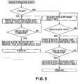
- the fixing roller 32a and the pressing roller 32c of the fixing device I are pressed against each other, and are rotated.
- the feeding roller 40a and the feeding roller 40b start rotation.
- the target temperature of the fixing roller 32a is 160°C, with which the toner image can be satisfactorily fixed on plain paper having the basis weight of less than 105 g/m 2 .
- the recording material having passed through the feeding roller 40a passes between the fixing roller 32b and the pressing roller 32d of the fixing device II which are kept apart from each other, without contact thereto, and is fed to the outside of the apparatus by the feeding rollers 40b.
- the glossiness of the image measure in the 60°method is approx. 15.
- the target temperature of the fixing roller 32b of the fixing device II is 180°C, and it is controlled to keep the temperature although the fixing roller 32b and the pressing roller 32d are spaced apart from each other.
- both of the fixing device I and the fixing device II are used.
- the fixing roller 32a and the pressing roller 32c of the fixing device I are pressed against each other, and start rotating, and also, the fixing roller 32b and the pressing roller 32d of the fixing device II are pressed against each other, and start rotating. Simultaneously, the feeding roller 40a and the feeding roller 40b start rotation.
- the target temperature of the fixing roller 32a is 160°C which is the same as with the case of the plain paper having the basis weight of less than 105 g/m 2 .
- the toner image is half-fixed on the recording material.
- the fixing strength at this time is enough to prevent removal of the toner from the recording material during feeding by the feeding roller 40a and enough to prevent toner offset to the fixing roller 32a. Therefore, the glossiness of the image is low, and the image is still not complete.
- the recording material is guided into the nip of the fixing device II by the feeding roller 40a and is subjected to the second image fixing.
- the target temperature of the fixing roller 32b is 180°C.
- the fixing strength becomes sufficiently high to raise the glossiness of the image, thus providing a satisfactory image quality.
- the glossiness of the image immediately after the fixing operation of the fixing device I is only approx. 5 in the 60°method, but is as high as approx. 15 after the fixing operation by the fixing device II.
- the recording material is fed to outside the apparatus by the feeding roller 40b when the recording material passes through the nip of the fixing device II.
- the recording material feeding speed (fixing speed) of the fixing device has to be lower than in the first image formation mode, in some cases, heretofore.
- the image formation is possible without the necessity of lowering the fixing speed, since the two fixing devices are used.
- the fixing condition is similar to the case of the second image formation mode for image formation on the recording material having a basis weight not less than 105 g/m 2 .
- the target temperature of the fixing device I is lower than in the above-described image formation mode (approx. 140°C, for example) in order to prevent image defect which may occur by the water vapor produced in the recording material burst out through the coating layer.
- the target temperature may 180°C which is the same as in the above-described image formation mode.
- the temperature control of the fixing device II is kept (180°C) always, even in the image formation mode not using the fixing device II.
- the time required by reaching the operable state from the actuation of the voltage source of the fixing device is approx. 4 min. In the case of the fixing device I, and is approx. 6 min. In the case of the fixing device II.
- the temperature control consumes the electric power wastefully, and thermal deterioration in various parts of the fixing device II is promoted.
- a switch is provided to control the fixing devices, respectively.
- the switch is provided on the operation panel (display portion) in the operating portion.
- the switch may be provided adjacent the associated fixing device. Or, both may be provided.
- the fixing devices may be selectively operable by a host computer (PC) connected with the printer via network cable (LAN)
- PC host computer
- LAN network cable
- the selectable modes by the switch is whether the stand-by temperature control is carried out for the fixing devices I and II or not, and whether the electric power supply to the fixing device II are stopped or not.
- the stand-by temperature control is carried out, it is possible to raise or lower the target temperature of the fixing roller.
- the description will be made as to the case in which the operation panel has the switch for setting and selecting the stand-by operation of the fixing device II (the operation when the image formation instructions to the image forming apparatus is not produced, and is awaited).
- the operation panel is placed at the position for the user's convenience.
- the switch on the operation panel can select one out of three states, namely, 180°C, 100°C and off state of the target temperature of the fixing device II during the stand-by state.
- the fixing roller 32b of the fixing device II is kept at 180°C during the fixing operation, and requires approx. 3 min. To restore from 100°C to -180 AC, and requires 6 min. At the maximum to restore from off-state to 180°C.
- king the target temperature of the fixing device II at 180°C during the stand-by state is convenient.
- shutting off the electric power supply to the fixing device II is advantageous.
- the electric power consumed by the entirety of the fixing device during the stand-by state can be reduced by approx. 60 %.
- the switch for setting the stand-by operation of the fixing device II is manually set by the operator, but it is a possible alternative to provide a controller to automatically switch the mode after a predetermined time elapses from completion of the image formation.
- the target temperature of the fixing device II is automatically switched from 180°C to 100°C.
- the electric power supply to the fixing device II is automatically shut off.
- the state of the fixing device II is kept the same, and only the fixing device I is used.
- the target temperature of the fixing device II is changed to 180°C automatically upon discrimination of such a kind by the image forming apparatus.
- the user may manually change the target temperature of the fixing device II, and the image forming operation is started upon confirmation of 180°C of the temperature of the fixing device II.
- the stand-by temperature of the fixing device II only (the temperature when the fixing device II is not used) is lowered automatically or manually.
- the stand-by temperature of the fixing device I may be simultaneously changed.
- the target temperature of the fixing device I is changed from 160°C to 90°C, and when 45 min. Elapsed, the electric power supply thereto is shut off.
- the timing at which the stand-by temperature of the fixing device I which is used in any image formation mode is lowered is after the timing at which the stand-by temperature of the fixing device II which is used only in a part of the image formation modes.
- timing of switching the stand-by temperature (the time from the completion of the image formation to the switching of the stand-by temperature) can be selectable by the operator on the operating portion.
- substantially the same fixing devices are used in the image forming apparatus, but two fixing devices of different types are usable, or three or more fixing devices may be used.
- the electric power consumed by the fixing device which is less frequently used is reduced.
- Figure 6 is a flow chart of the control when the energy saving key is depressed in the operating portion 219.
- Figure 7 shows the control operations with time. The ordinate represents the fixing temperature, and the abscissa represents the time.
- the fixing heaters of the fixing rollers 32a/b are supplied with the electric power (S300) to keep the target temperature.
- the controller 200 discriminates as to whether or not it accepts a first job (image formation job) produced by depression of the copying operation start key by the user.
- the discrimination at step S304 is that controller 200 does not accept the first job, the operation returns to step S301, and similar operation is repeated (polling).
- the discrimination at step S304 is that controller 200 accept the first job, it is discriminated whether or not the conditions of the process satisfy at least one of predetermined conditions (S305).
- S305 The contents of the discrimination at the step S305 will be described hereinafter.
- step S310 if the discrimination indicates that recording material used is a thick sheet or poor paper, the condition is deem as being met (S315), and the comparing operation ends.
- the detection of the kind of the recording material may be made on the basis of the setting in the operating portion 219 by the user or may be automatically made by a sensor such as a photo-interruptor.
- the heat is absorbed by the sheet when it passes through the fixing roller 32a, with the possible result of insufficient fixing property. Therefore, in the case of the thick sheet or poor paper, it is preferably passed through fixing device having the fixing roller 32b to assure the fixing property.
- step S311 When the controller 200 discriminates at step S311 that formation of high glossiness image is necessary on the basis of the image data, the condition is deemed as being met (S315), and the comparison sequence ends.
- a ratio of the image data and the letter data of the image data stored in the image memory is detected by image area separation or the like, and if the ratio of the image data is high, it is discriminated that formation of the high glossiness image is necessary.
- the user can set at the operating portion 219.
- the fixing property is satisfied by passing the upstream fixing device having the fixing roller 32a, but by passing the downstream fixing device having the fixing roller 32b, a high glossiness can be provided.
- step S312 When the discrimination by the controller 200 at step S312 indicates that ambient temperature exceeds a predetermined temperature, the condition is deemed as being met (S315), and the comparison sequence ends.
- a high ambient temperature means high fixing property on the recording material, and therefore, the fixing operation by the fixing device having the fixing roller 32b is not required.
- the predetermined temperature can be properly selected by one skilled in the art. Therefore, the discrimination as to whether or not the ambient temperature exceeds the predetermined temperature is preferable.
- a high temperature of the recording material means high fixing property on the recording material, and therefore, the fixing operation by the fixing device having the fixing roller 32b is not required.
- the predetermined temperature can be selected properly by one skilled in the art. Therefore, it is preferable that discrimination is made as to whether or not the temperature of the recording material exceeds the predetermined temperature.
- the temperature of the recording material is detected, but this may be replaced with the discrimination as to whether or not the both sides image forming operation is carried out. This is because in the case of the both sides operation, the temperature of the recording material is high if the recording material has passed through the fixing device having the fixing roller 32a in the first side image formation. In the case that both sides image forming operation is not carried out, the condition is deemed as being satisfied (S315), and the comparison sequence ends.
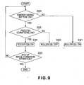
- the controller 200 discriminates whether or not the energy saving key is depressed in the operating portion 219 during the image formation (S320).
- step S320 If the electric power supply has already been started, nothing is done here. If the result of the discrimination at the step S320 is affirmative, it is discriminated whether or not the conditions of the process satisfy at least one of predetermined conditions (S322). The content of the discrimination at S322 are the same as the foregoing.
- step S322 If the predetermined condition is met at step S322, the electric power supply to the heater of the fixing roller 32b is started (S323). If the electric power supply has already been started, nothing is done.
- the controller 200 discriminations whether or not the image forming operation is finished (S325).
- step S325 If the result of the discrimination at the step S325 is affirmative, the operation returns to the step S301 of Figure 6 (Embodiment 2), the sequence for the time from the actuation of the main switch to immediately before the image forming operation is carried out.
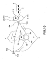
- FIG 10 is a schematic view of an example of a fixing device used in the image forming apparatus according to an embodiment of the present invention.
- a fixing device III is the same as the foregoing fixing device I, and a fixing device IV is the same as the foregoing fixing device II, and therefore, the detailed description therefor is omitted for simplicity.
- the recording material passes through the pair of the feeding rollers 40a, the recording material is guided to either one of the two feeding paths by the feeding path switching guide 1050.
- the feeding path switching guide is controlled by a controller 200.
- the fixing operation is carried out only by the fixing device III.
- the feeding path switching guide 1050 moves to guide the recording material to the bypass path to avoid the fixing device. Then, the recording material is passed through the feeding path X, and is fed to the sheet discharging roller 1145, and then, is discharged by the sheet discharging rollers 1145.
- the recording material has a basis weight not less than 105 g/m 2 , or it is coated paper
- two fixing devices are used. After the recording material is subjected to the fixing operation in the fixing device III, it passes through the pair of the sheet discharging rollers 40a, and then, is immediately guided to the fixing device feeding path Y by the feeding path switching guide 1050. The recording material is subjected to the fixing operation by the fixing device IV, the recording material is guided toward the sheet discharging rollers 1145 by the feeding path switching guide 1150, and then, is discharged by the sheet discharging roller 1145.
- the number of the fixing devices is changed in accordance with the kind of the recording material to be used.
- the fixing roller 32b and the pressing roller 32d of the fixing device II are spaced from each other, and the recording material P is passed through therebetween.
- the recording material in the case that image is fixed without use of the fixing device IV, the recording material is fed along the recording material feeding path X exclusively for that case, and therefore, the recording material can be stably fed.
- the by-pass path may be utilized for one or more of various controls such as inclination correction of the recording material feeding, curl rectification and the like.
- the fixing device IV is disposed below the by-pass path, but they may be reverted.
- the operating condition of the fixing device which is used less frequently can be set by the user, the usability is improved.
Landscapes
- Physics & Mathematics (AREA)
- General Physics & Mathematics (AREA)
- Engineering & Computer Science (AREA)
- Microelectronics & Electronic Packaging (AREA)
- Fixing For Electrophotography (AREA)
- Control Or Security For Electrophotography (AREA)
Applications Claiming Priority (2)
| Application Number | Priority Date | Filing Date | Title |
|---|---|---|---|
| JP2004309554A JP4617135B2 (ja) | 2004-10-25 | 2004-10-25 | 画像形成装置 |
| EP05023323A EP1650036B1 (en) | 2004-10-25 | 2005-10-25 | Image forming apparatus and image forming method |
Related Parent Applications (3)
| Application Number | Title | Priority Date | Filing Date |
|---|---|---|---|
| EP05023323A Division EP1650036B1 (en) | 2004-10-25 | 2005-10-25 | Image forming apparatus and image forming method |
| EP05023323A Division-Into EP1650036B1 (en) | 2004-10-25 | 2005-10-25 | Image forming apparatus and image forming method |
| EP05023323.8 Division | 2005-10-25 |
Publications (3)
| Publication Number | Publication Date |
|---|---|
| EP1837190A2 EP1837190A2 (en) | 2007-09-26 |
| EP1837190A3 EP1837190A3 (en) | 2007-10-10 |
| EP1837190B1 true EP1837190B1 (en) | 2011-10-12 |
Family
ID=35708780
Family Applications (2)
| Application Number | Title | Priority Date | Filing Date |
|---|---|---|---|
| EP07013730A Expired - Lifetime EP1837190B1 (en) | 2004-10-25 | 2005-10-25 | Image forming apparatus and image forming method |
| EP05023323A Ceased EP1650036B1 (en) | 2004-10-25 | 2005-10-25 | Image forming apparatus and image forming method |
Family Applications After (1)
| Application Number | Title | Priority Date | Filing Date |
|---|---|---|---|
| EP05023323A Ceased EP1650036B1 (en) | 2004-10-25 | 2005-10-25 | Image forming apparatus and image forming method |
Country Status (5)
| Country | Link |
|---|---|
| US (2) | US7639962B2 (https=) |
| EP (2) | EP1837190B1 (https=) |
| JP (1) | JP4617135B2 (https=) |
| CN (1) | CN1766758B (https=) |
| DE (1) | DE602005027157D1 (https=) |
Families Citing this family (10)
| Publication number | Priority date | Publication date | Assignee | Title |
|---|---|---|---|---|
| JP4262140B2 (ja) | 2004-06-07 | 2009-05-13 | キヤノン株式会社 | 画像形成装置 |
| JP4250623B2 (ja) * | 2005-08-31 | 2009-04-08 | キヤノン株式会社 | 画像形成装置及び光沢度制御方法 |
| JP4701050B2 (ja) * | 2005-09-13 | 2011-06-15 | キヤノン株式会社 | 画像形成装置 |
| JP4298754B2 (ja) * | 2007-01-31 | 2009-07-22 | キヤノン株式会社 | 画像形成装置及び画像形成方法 |
| JP5279338B2 (ja) * | 2008-05-12 | 2013-09-04 | キヤノン株式会社 | 印刷装置及び印刷装置の制御方法及びプログラム |
| JP2010168141A (ja) * | 2009-01-21 | 2010-08-05 | Konica Minolta Business Technologies Inc | 画像形成装置 |
| JP5402314B2 (ja) | 2009-03-17 | 2014-01-29 | 株式会社リコー | 定着装置及び画像形成装置 |
| WO2012022996A1 (en) | 2010-08-18 | 2012-02-23 | Thomson Licensing | Methods for operating an apparatus having multiple stand-by modes |
| JP6242123B2 (ja) * | 2013-09-02 | 2017-12-06 | キヤノン株式会社 | 画像形成装置、及び画像形成装置の制御方法 |
| US10105902B2 (en) * | 2016-04-18 | 2018-10-23 | Evolve Additive Solutions, Inc. | Electrophotography-based additive manufacturing with part molding |
Family Cites Families (25)
| Publication number | Priority date | Publication date | Assignee | Title |
|---|---|---|---|---|
| JPH01100583A (ja) * | 1987-10-14 | 1989-04-18 | Tokyo Electric Co Ltd | レーザプリンタ |
| JPH04282653A (ja) * | 1991-03-12 | 1992-10-07 | Casio Electron Mfg Co Ltd | 画像形成装置 |
| JPH05323710A (ja) * | 1992-05-26 | 1993-12-07 | Ricoh Co Ltd | 画像形成装置 |
| JPH07271226A (ja) * | 1994-03-29 | 1995-10-20 | Matsushita Electric Ind Co Ltd | 画像形成装置 |
| JPH10207287A (ja) | 1997-01-20 | 1998-08-07 | Ricoh Co Ltd | 定着装置及びそれを用いた画像形成装置及び定着装置の温度熱容量制御方法 |
| JP3524352B2 (ja) * | 1997-11-14 | 2004-05-10 | キヤノン株式会社 | 節電制御装置 |
| KR100311019B1 (ko) * | 1998-08-07 | 2002-02-19 | 윤종용 | 인쇄기의 열원들에 대한 전력 공급 제어방법 및 그 전력 공급제어장치 |
| JP2000214709A (ja) * | 1999-01-22 | 2000-08-04 | Canon Inc | 画像形成装置 |
| JP2000221820A (ja) * | 1999-02-03 | 2000-08-11 | Minolta Co Ltd | 定着装置 |
| JP2000221821A (ja) * | 1999-02-03 | 2000-08-11 | Minolta Co Ltd | 定着装置 |
| JP2001042673A (ja) | 1999-08-04 | 2001-02-16 | Ricoh Co Ltd | 印刷装置 |
| JP2001194947A (ja) * | 2000-01-07 | 2001-07-19 | Canon Inc | 像加熱装置及び画像形成装置 |
| JP2002049258A (ja) | 2000-08-01 | 2002-02-15 | Canon Inc | 定着装置及び画像形成装置 |
| JP2002365967A (ja) * | 2001-06-12 | 2002-12-20 | Canon Inc | 画像形成装置 |
| JP3758029B2 (ja) * | 2001-06-18 | 2006-03-22 | 富士ゼロックス株式会社 | 画像形成装置及びこれに用いられる定着ユニット |
| JP2003162200A (ja) * | 2001-11-29 | 2003-06-06 | Canon Inc | 画像形成装置 |
| JP3945281B2 (ja) * | 2002-03-19 | 2007-07-18 | 富士ゼロックス株式会社 | 画像形成装置 |
| JP2004086039A (ja) * | 2002-08-28 | 2004-03-18 | Murata Mach Ltd | 定着装置 |
| JP2004246040A (ja) * | 2003-02-13 | 2004-09-02 | Canon Inc | 画像形成装置 |
| JP2005049563A (ja) * | 2003-07-31 | 2005-02-24 | Canon Inc | 定着装置及びこれを備えた画像形成装置 |
| US6987251B2 (en) * | 2003-12-24 | 2006-01-17 | Canon Kabushiki Kaisha | Heating apparatus with temperature detection system for identifying and notifying the user that the material to be heated is wound around the induction heating element |
| JP4227545B2 (ja) * | 2004-03-16 | 2009-02-18 | キヤノン株式会社 | 画像形成装置 |
| JP4262140B2 (ja) * | 2004-06-07 | 2009-05-13 | キヤノン株式会社 | 画像形成装置 |
| JP4594063B2 (ja) * | 2004-12-20 | 2010-12-08 | キヤノン株式会社 | 像加熱装置 |
| JP4794890B2 (ja) * | 2005-04-08 | 2011-10-19 | キヤノン株式会社 | 画像形成装置 |
-
2004
- 2004-10-25 JP JP2004309554A patent/JP4617135B2/ja not_active Expired - Fee Related
-
2005
- 2005-10-25 EP EP07013730A patent/EP1837190B1/en not_active Expired - Lifetime
- 2005-10-25 CN CN2005101160189A patent/CN1766758B/zh not_active Expired - Fee Related
- 2005-10-25 US US11/256,936 patent/US7639962B2/en not_active Expired - Fee Related
- 2005-10-25 EP EP05023323A patent/EP1650036B1/en not_active Ceased
- 2005-10-25 DE DE602005027157T patent/DE602005027157D1/de not_active Expired - Lifetime
-
2008
- 2008-01-15 US US12/014,315 patent/US7412182B2/en not_active Expired - Lifetime
Also Published As
| Publication number | Publication date |
|---|---|
| EP1837190A3 (en) | 2007-10-10 |
| CN1766758A (zh) | 2006-05-03 |
| US7639962B2 (en) | 2009-12-29 |
| EP1650036B1 (en) | 2011-03-30 |
| EP1837190A2 (en) | 2007-09-26 |
| EP1650036A2 (en) | 2006-04-26 |
| EP1650036A3 (en) | 2007-03-14 |
| US7412182B2 (en) | 2008-08-12 |
| JP4617135B2 (ja) | 2011-01-19 |
| JP2006119517A (ja) | 2006-05-11 |
| US20080118267A1 (en) | 2008-05-22 |
| DE602005027157D1 (de) | 2011-05-12 |
| CN1766758B (zh) | 2010-12-08 |
| US20070140717A1 (en) | 2007-06-21 |
Similar Documents
| Publication | Publication Date | Title |
|---|---|---|
| US7412182B2 (en) | Image forming apparatus with setting of an operating condition of at least one image heating device | |
| US4719489A (en) | Recording apparatus having material feed mode dependent fixing control | |
| EP2136267B1 (en) | Image Forming Apparatus | |
| US8311431B2 (en) | Image forming apparatus comprising a control section configured to carry out a control process including setting a power saving mode | |
| EP2607964A2 (en) | Fixing device | |
| US6952541B2 (en) | Fixing apparatus | |
| US20070086803A1 (en) | Image-heating device with a first heating member and an adjustable second heating member | |
| JP2005221753A (ja) | 画像形成装置 | |
| US7315702B2 (en) | Image forming apparatus capable of reducing time unable to perform image formation due to temperature change of image bearing member | |
| JP5488861B2 (ja) | 画像形成装置、および画像形成装置におけるウォームアップ時間制御方法 | |
| US7593658B2 (en) | Image forming apparatus | |
| US7242881B2 (en) | Image forming apparatus having advanced fixing system | |
| JP2010164757A (ja) | 画像形成装置 | |
| US20090060553A1 (en) | Image forming apparatus | |
| JP2000259034A (ja) | 画像形成装置 | |
| US11644771B2 (en) | Image forming apparatus | |
| JPH08211779A (ja) | 定着装置 | |
| JP2006153934A (ja) | 画像形成システム | |
| JP2003173106A (ja) | 画像形成装置 | |
| JP2000259036A (ja) | 画像形成装置 | |
| JP2002258663A (ja) | 熱定着装置及び画像形成装置 | |
| JP2008145451A (ja) | 定着装置および画像形成装置 |
Legal Events
| Date | Code | Title | Description |
|---|---|---|---|
| PUAI | Public reference made under article 153(3) epc to a published international application that has entered the european phase |
Free format text: ORIGINAL CODE: 0009012 |
|
| PUAL | Search report despatched |
Free format text: ORIGINAL CODE: 0009013 |
|
| AC | Divisional application: reference to earlier application |
Ref document number: 1650036 Country of ref document: EP Kind code of ref document: P |
|
| AK | Designated contracting states |
Kind code of ref document: A2 Designated state(s): AT BE BG CH CY CZ DE DK EE ES FI FR GB GR HU IE IS IT LI LT LU LV MC NL PL PT RO SE SI SK TR |
|
| AX | Request for extension of the european patent |
Extension state: AL BA HR MK YU |
|
| AK | Designated contracting states |
Kind code of ref document: A3 Designated state(s): AT BE BG CH CY CZ DE DK EE ES FI FR GB GR HU IE IS IT LI LT LU LV MC NL PL PT RO SE SI SK TR |
|
| AX | Request for extension of the european patent |
Extension state: AL BA HR MK YU |
|
| 17P | Request for examination filed |
Effective date: 20080410 |
|
| AKX | Designation fees paid |
Designated state(s): DE FR GB IT |
|
| 17Q | First examination report despatched |
Effective date: 20080616 |
|
| GRAP | Despatch of communication of intention to grant a patent |
Free format text: ORIGINAL CODE: EPIDOSNIGR1 |
|
| GRAS | Grant fee paid |
Free format text: ORIGINAL CODE: EPIDOSNIGR3 |
|
| GRAA | (expected) grant |
Free format text: ORIGINAL CODE: 0009210 |
|
| AC | Divisional application: reference to earlier application |
Ref document number: 1650036 Country of ref document: EP Kind code of ref document: P |
|
| AK | Designated contracting states |
Kind code of ref document: B1 Designated state(s): DE FR GB IT |
|
| REG | Reference to a national code |
Ref country code: GB Ref legal event code: FG4D |
|
| REG | Reference to a national code |
Ref country code: DE Ref legal event code: R096 Ref document number: 602005030637 Country of ref document: DE Effective date: 20111208 |
|
| PLBE | No opposition filed within time limit |
Free format text: ORIGINAL CODE: 0009261 |
|
| STAA | Information on the status of an ep patent application or granted ep patent |
Free format text: STATUS: NO OPPOSITION FILED WITHIN TIME LIMIT |
|
| PG25 | Lapsed in a contracting state [announced via postgrant information from national office to epo] |
Ref country code: IT Free format text: LAPSE BECAUSE OF FAILURE TO SUBMIT A TRANSLATION OF THE DESCRIPTION OR TO PAY THE FEE WITHIN THE PRESCRIBED TIME-LIMIT Effective date: 20111012 |
|
| 26N | No opposition filed |
Effective date: 20120713 |
|
| REG | Reference to a national code |
Ref country code: FR Ref legal event code: ST Effective date: 20120817 |
|
| REG | Reference to a national code |
Ref country code: DE Ref legal event code: R097 Ref document number: 602005030637 Country of ref document: DE Effective date: 20120713 |
|
| PG25 | Lapsed in a contracting state [announced via postgrant information from national office to epo] |
Ref country code: FR Free format text: LAPSE BECAUSE OF NON-PAYMENT OF DUE FEES Effective date: 20111212 |
|
| PGFP | Annual fee paid to national office [announced via postgrant information from national office to epo] |
Ref country code: GB Payment date: 20201027 Year of fee payment: 16 |
|
| PGFP | Annual fee paid to national office [announced via postgrant information from national office to epo] |
Ref country code: DE Payment date: 20201228 Year of fee payment: 16 |
|
| REG | Reference to a national code |
Ref country code: DE Ref legal event code: R119 Ref document number: 602005030637 Country of ref document: DE |
|
| GBPC | Gb: european patent ceased through non-payment of renewal fee |
Effective date: 20211025 |
|
| PG25 | Lapsed in a contracting state [announced via postgrant information from national office to epo] |
Ref country code: GB Free format text: LAPSE BECAUSE OF NON-PAYMENT OF DUE FEES Effective date: 20211025 Ref country code: DE Free format text: LAPSE BECAUSE OF NON-PAYMENT OF DUE FEES Effective date: 20220503 |