EP1789370B1 - Beschichtetes bauteil aus quarzglas sowie verfahren zur herstellung des bauteils - Google Patents
Beschichtetes bauteil aus quarzglas sowie verfahren zur herstellung des bauteils Download PDFInfo
- Publication number
- EP1789370B1 EP1789370B1 EP05781997.1A EP05781997A EP1789370B1 EP 1789370 B1 EP1789370 B1 EP 1789370B1 EP 05781997 A EP05781997 A EP 05781997A EP 1789370 B1 EP1789370 B1 EP 1789370B1
- Authority
- EP
- European Patent Office
- Prior art keywords
- sio
- quartz glass
- glass
- base body
- mass
- Prior art date
- Legal status (The legal status is an assumption and is not a legal conclusion. Google has not performed a legal analysis and makes no representation as to the accuracy of the status listed.)
- Expired - Lifetime
Links
Images
Classifications
-
- C—CHEMISTRY; METALLURGY
- C03—GLASS; MINERAL OR SLAG WOOL
- C03C—CHEMICAL COMPOSITION OF GLASSES, GLAZES OR VITREOUS ENAMELS; SURFACE TREATMENT OF GLASS; SURFACE TREATMENT OF FIBRES OR FILAMENTS MADE FROM GLASS, MINERALS OR SLAGS; JOINING GLASS TO GLASS OR OTHER MATERIALS
- C03C17/00—Surface treatment of glass, not in the form of fibres or filaments, by coating
- C03C17/22—Surface treatment of glass, not in the form of fibres or filaments, by coating with other inorganic material
- C03C17/23—Oxides
- C03C17/25—Oxides by deposition from the liquid phase
-
- C—CHEMISTRY; METALLURGY
- C03—GLASS; MINERAL OR SLAG WOOL
- C03B—MANUFACTURE, SHAPING, OR SUPPLEMENTARY PROCESSES
- C03B19/00—Other methods of shaping glass
- C03B19/06—Other methods of shaping glass by sintering, e.g. by cold isostatic pressing of powders and subsequent sintering, by hot pressing of powders, by sintering slurries or dispersions not undergoing a liquid phase reaction
- C03B19/066—Other methods of shaping glass by sintering, e.g. by cold isostatic pressing of powders and subsequent sintering, by hot pressing of powders, by sintering slurries or dispersions not undergoing a liquid phase reaction for the production of quartz or fused silica articles
-
- C—CHEMISTRY; METALLURGY
- C03—GLASS; MINERAL OR SLAG WOOL
- C03C—CHEMICAL COMPOSITION OF GLASSES, GLAZES OR VITREOUS ENAMELS; SURFACE TREATMENT OF GLASS; SURFACE TREATMENT OF FIBRES OR FILAMENTS MADE FROM GLASS, MINERALS OR SLAGS; JOINING GLASS TO GLASS OR OTHER MATERIALS
- C03C17/00—Surface treatment of glass, not in the form of fibres or filaments, by coating
- C03C17/02—Surface treatment of glass, not in the form of fibres or filaments, by coating with glass
-
- C—CHEMISTRY; METALLURGY
- C03—GLASS; MINERAL OR SLAG WOOL
- C03C—CHEMICAL COMPOSITION OF GLASSES, GLAZES OR VITREOUS ENAMELS; SURFACE TREATMENT OF GLASS; SURFACE TREATMENT OF FIBRES OR FILAMENTS MADE FROM GLASS, MINERALS OR SLAGS; JOINING GLASS TO GLASS OR OTHER MATERIALS
- C03C2217/00—Coatings on glass
- C03C2217/20—Materials for coating a single layer on glass
- C03C2217/21—Oxides
- C03C2217/213—SiO2
-
- Y—GENERAL TAGGING OF NEW TECHNOLOGICAL DEVELOPMENTS; GENERAL TAGGING OF CROSS-SECTIONAL TECHNOLOGIES SPANNING OVER SEVERAL SECTIONS OF THE IPC; TECHNICAL SUBJECTS COVERED BY FORMER USPC CROSS-REFERENCE ART COLLECTIONS [XRACs] AND DIGESTS
- Y10—TECHNICAL SUBJECTS COVERED BY FORMER USPC
- Y10T—TECHNICAL SUBJECTS COVERED BY FORMER US CLASSIFICATION
- Y10T428/00—Stock material or miscellaneous articles
- Y10T428/26—Web or sheet containing structurally defined element or component, the element or component having a specified physical dimension
Definitions
- the invention relates to a quartz glass component, comprising a base body of quartz glass whose surface is at least partially covered with a glass mass, which differs in their optical, physical or chemical properties of the quartz glass of the base body.
- the invention relates to a method for producing a coated component made of quartz glass by the surface of a base body made of quartz glass is at least partially covered with a SiO 2 glass mass, which differs in their optical, physical or chemical properties of the quartz glass of the base body ,
- Quartz glass is characterized by a low coefficient of expansion, by optical transparency over a wide wavelength range and by high chemical and thermal resistance. Quartz glass components are used for a variety of applications, such as in lamp manufacturing as cladding, pistons, cover plates or reflector support for lamps and radiators in the ultraviolet, infrared and visible spectral range, or in semiconductor manufacturing in the form of reactors and apparatus of quartz glass for the Treatment of semiconductor devices, carrier trays, bells, crucibles, protective shields or simple quartz glass components, such as tubes, rods, plates, flanges, rings or blocks. To produce special properties, quartz glass is doped with other substances.
- the fused silica components are exposed to high thermal stresses and chemically aggressive environments.
- a good heat insulation, a high temperature stability or thermal shock resistance as well as a high chemical resistance and freedom from contamination play an important role.
- Increasingly higher demands are placed on the service life of such quartz glass components.
- quartz glass-reactive, fluorine-containing process gases such as CHF 3 or CF 4
- CHF 3 or CF 4 can shorten the life of a quartz glass component by etching.
- the formation of the surface layer is effected by a relative movement of the deposition burner and the component surface to be coated to each other, wherein the layer growth depends on the current deposition rate and the number of layer layers.
- the invention has for its object to provide a cost-effective component made of quartz glass, especially for use in semiconductor manufacturing, which is characterized by high purity, by high etch resistance (and thus a long service life), and as possible no particle problems.
- the invention has for its object to provide a method for producing a SiO 2 glass mass on a quartz glass component, which can be produced relatively inexpensively and reproducibly and in any strength and shape, and can fulfill different functions depending on their specific design , especially in semiconductor manufacturing.
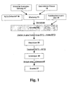
- this object is achieved on the basis of the above-mentioned method according to the invention by producing a slurry containing amorphous SiO 2 particles and applying it to the surface of the base body to form a slip layer, drying the slip layer and then forming it the SiO 2 glass mass is vitrified.
- the production of the coating of the quartz glass base body is carried out via a slip route.
- the volume of the SiO 2 glass mass is formed completely, or at least to a substantial extent, of SiO 2 , which is processed and provided by a slurry process.
- a particular technical challenge is to avoid cracking of the slip layer during drying or vitrification, although the volume of the layer shrinks without the quartz glass of the base body being able to yield accordingly.
- an aqueous, homogeneous, stable and pourable slurry is first produced which contains amorphous SiO 2 particles.
- the slurry is applied as a "slip layer" on the base body and then dried and vitrified.
- the amorphous SiO 2 particles already stabilize the slurry layer in a pasty and dry state and promote sintering activity, allowing sintering of the dried slurry layer at a comparatively low temperature to form a dense, crack-free SiO 2 glass mass ,
- the SiO 2 particles consist of synthetically produced SiO 2 or of purified naturally occurring raw material, as described in the above-mentioned DE 44 40 104 C2 is described.
- the particle size and distribution of the SiO 2 particles has effects on the rheological properties of the slurry, on dry shrinkage of the slip layer and on the surface roughness of the resulting SiO 2 glass mass.
- the intrinsic viscosity can be increased, the drying shrinkage can be reduced and the surface roughness of the SiO 2 glass mass can be increased.
- the drying of the slip layer is carried out by removal of moisture at room temperature, by heating or by freeze-drying.
- the slip layer is vitrified by heating to a high temperature which results in sintering of the SiO 2 particles and formation of a dense, crack-free glass mass of opaque, partially opaque, and partially transparent or fully transparent SiO 2 , and covering the entire surface of the base body or part of it.
- the SiO 2 glass mass is in the form of a flat layer or it forms a shape which constitutes a functional component of the component, for example as a thickening or bead.
- the base body is a body of quartz glass made of synthetically produced or naturally occurring raw materials.
- the quartz glass of the base body may be transparent or opaque (translucent).
- SiO 2 particles are preferably used for the formation of the glass mass, the particle size in the range up to a maximum of 500 .mu.m, preferably at most 100 .mu.m, wherein SiO 2 particles with particle sizes in the range between 1 .mu.m and 50 .mu.m account for the largest volume fraction.
- SiO 2 particles in this size range show an advantageous sintering behavior and a comparatively low drying shrinkage. It has been shown that in such a slurry, the slip layer can be dried and glazed particularly easily without cracking. This may be due to a sufficiently low dry shrinkage and interactions of the SiO 2 particles with each other, which can lead to the formation of molecular SiO 2 bonds, and facilitate drying and sintering.
- the desired particle size distribution is set by the homogenization process of the aqueous slurry, wherein the SiO 2 particles are reduced starting from relatively coarse grains with diameters, for example in the range between 200 microns and 5000 microns during homogenization depending on their degree of solidification.
- SiO 2 particles of any size are formed within the slurry, even those which, as a result of interactions with one another, already form the bonds and bonds described above in the slurry, which improves the stability of the slurry layer.
- the cristobalite content in the dried SiO 2 slurry layer should be at most 1% by weight, otherwise crystallization may occur during vitrification of the slurry layer, which may result in rejection of the component.
- Roughening the surface of the base body causes better adhesion of both the slurry layer and the dense SiO 2 glass mass produced therefrom by vitrification.
- the roughening is done mechanically (for example by grinding or sandblasting) or chemically (by etching), the surface should have a mean roughness R a of at least 0.5 microns.
- the per se known processing techniques are suitable, such as spraying, electrostatically assisted spraying, flooding, spinning, dipping, printing, drawing and stripping (Doctor Blade method) or brushing.
- the vitrification of the dried slurry layer preferably takes place at a low maximum temperature in the range between 1000 ° C. and 1600 ° C., preferably between 1100 ° C. and 1400 ° C., compared with the method described above.
- the low maximum temperature prevents too rapid compaction of the outer surface areas of the slip layer during vitrification. Such rapid compaction, due to its heat-insulating effect, would hinder the further progression of a glazing front, thereby complicating complete vitrification or the formation of thick glazed layers.
- vitrification of the dried slurry layer takes place in a hydrogen atmosphere.
- vitrification process under hydrogen is relatively expensive.
- vitrification of the dried slurry layer can take place under air.
- a vitrification in air usually leads to opaque SiO 2 glass masses.
- slip layers in air can be vitrified to a transparent layer up to layer thicknesses of about 4 mm, provided that the base body itself consists of transparent quartz glass. Glazing in air requires no special safety precautions and is inexpensive.
- vitrification in an oven it has also proven useful if the vitrification of the dried slurry layer takes place by means of a burner flame.
- This process variant results in a likewise crack-free, flame-polished surface, wherein the heat action is temporally short and can be easily limited to the areas that are covered with an SiO 2 -Schlicker Mrs to be glazed, so that plastic deformation can be largely avoided.
- a surface glazed by laser exhibits relatively few bubbles compared to a surface glazed by means of a burner flame.
- the customary burner gases such as oxygen and hydrogen, which lead to the formation and inclusion of water or hydroxyl groups in the quartz glass, are not present or are present in lesser amounts in "laser glazing". This results in a significant improvement in the etch resistance of the component with low particle generation.
- the layer can be successively reinforced by performing the method according to the invention several times.
- This process variant is advantageously used, for example, when the SiO 2 glass mass is formed as a partial thickening of the base body.
- the regional thickening of the base body can fulfill a variety of functions.
- a cylindrical base body it can serve as a circumferential bead for holding or sealing against contact with a counterpart, or as a terminal thickening of a rod-shaped or tubular base body from which a predetermined final shape is mechanically worked, such as, for example, a spherical ground section or a Flange.
- a dopant or a plurality of dopants are introduced into the SiO 2 -Glasmasse, which develop a specific effect in quartz glass, such as a coloring effect or a gas structure stiffening effect.
- a specific effect in quartz glass such as a coloring effect or a gas structure stiffening effect.
- an addition of aluminum in the quartz glass of the glass composition Al 2 O 3 which increases the etch resistance of quartz glass and thus leads to an extension of the life of the quartz glass component.
- Similar additions of nitrogen or carbon which are incorporated in the form of nitrides or carbides in the quartz glass structure, and effect a stiffening of the glass structure and thus also to a better etch resistance.
- Suitable starting substances for example silazanes or siloxanes, are distributed particularly uniformly in the slurry, which ultimately results in homogeneous doping of the quartz glass of the glass mass.
- a particularly advantageous effect with respect to the dry etching resistance of the component is achieved by an addition of yttrium, which is present in the quartz glass as Y 2 O 3 .
- the SiO 2 glass mass produced in this way is distinguished by high adhesive strength on quartz glass and is easily modifiable in its properties by simple process changes, such as the glazing temperature or the addition of dopants, and can be adapted to a large number of specific applications. Suitable designs for use in semiconductor manufacturing are described in more detail below.
- the abovementioned object starting from the quartz glass component described above, is achieved according to the invention in that the glass mass is produced from a dried, vitrified slip mass containing amorphous SiO 2 particles.
- Such a SiO 2 glass mass is obtained by applying a mass of SiO 2 particles containing slip on the surface of the base body, and by subsequent drying and vitrification of the mass, as explained in more detail above for the inventive method.
- the SiO 2 glass mass consists entirely or for the most part of SiO 2 , which has been prepared and applied by means of the slip method, and covers the component surface completely or only partially. It forms a flat layer on the component surface or it contributes to the geometric shape of the component and thereby forms a functional component of the component, such as a thickening or a bead, which can serve as a flange or ground joint, for example.
- a smooth and dense surface is required, this is preferably obtained by Feuerpolitur.
- the surface of the SiO 2 glass mass thus produced is obtained without tools in the melt flow by vitrification by means of a burner flame or in an oven and is characterized at least by freedom from cracks and it can be processed chemically and mechanically, for example by grinding, polishing or blasting.
- the SiO 2 glass mass is formed with a crack-free and tool-free shaped surface having an average surface roughness R a of at least 0.5 ⁇ m.
- the surface of the SiO 2 glass mass after vitrification is not particularly smooth, but on the contrary, it is characterized by a certain surface roughness.
- the surface roughness results as a result of their preparation by means of the method according to the invention by the use of a SiO 2 particles containing slip for the formation of the glass mass.
- a roughness of the surface arises automatically after vitrification without the need for further measures such as roughening or mechanically roughening surface treatment.
- the "natural" roughness of the surface of the component according to the invention predestines it for use in semiconductor production. Because it causes a better adhesion of material layers and thus leads to a lower particle load when using the component in the semiconductor manufacturing. In addition, the component allows an extension of the cleaning cycles and thus shows a longer service life.
- the definition of the surface roughness R a results from EN ISO 4287, the measurement conditions from EN ISO 4288 (here the case of a non-periodic surface profile is present).
- the mean surface roughness R a of the SiO 2 glass mass is at least 0.5 ⁇ m, preferably at least 1.0 ⁇ m.
- the SiO 2 glass mass in relation to the base body consists of species-specific material.
- a “species-specific material” is understood here to mean that the SiO 2 contents of the glass mass and base body differ from one another by a maximum of 3% by weight, and that in the presence of dopants in the glass mass or in the quartz glass of the base body, these coefficients of expansion on both sides similar way. As a result, a particularly good adhesion of the glass mass to the base body, and in particular a high thermal shock resistance of this composite is achieved.
- the SiO 2 glass mass can be opaque, partially opaque and transparent or completely transparent.
- the complete transparency of the SiO 2 glass mass is preferred when it comes to a high density, freedom from pores and good etch resistance.
- An opaque SiO 2 glass mass is usually white, reflects infrared radiation and therefore has a good heat insulating effect.
- the SiO 2 glass mass forms a thickened region of the base body.
- the thickened region is formed, for example, as a bead or terminal region of a cylindrical base body. He comes in the directly generated form or after finishing a predetermined function, for example, to hold the component to.
- the SiO 2 glass mass contains dopants in the form of yttrium, aluminum, nitrogen, carbon or their compounds.
- a homogeneous base slip is produced.
- base slip SiO 2 water slurry
- quartz glass drum mill with about 20 liters volume content
- 8.2 kg amorphous quartz glass grains of natural raw material with particle sizes in the range between 250 microns and 650 microns 1.8 kg of deionized water mixed with a conductivity of less than 3 ⁇ S.
- the quartz glass grain was previously cleaned in a H exertchloriervon; Care is taken that the cristobalite content is less than 1% by weight.
- the amorphous SiO 2 granules having a particle size of about 5 ⁇ m are admixed to the homogeneous base slip so obtained until a solids content of 84% by weight has been reached.
- the mixture is homogenised for 12 hours in a drum mill at a speed of 25 rpm.
- the resulting slurry has a solids content of 84% and a density of 2.0 g / cm 3 .
- the SiO 2 particles in the slip 14 obtained after milling the quartz glass grains show a particle size distribution which is characterized by a D 50 value of about 8 ⁇ m and by a D 90 value of about 40 ⁇ m.
- a ring-shaped quartz glass flange having an outer diameter of 300 mm for a single-wafer holder, the surface of which has been set in advance by chemical etching (freezing) to a mean surface roughness R a of 2 microns.
- This slip layer is first dried for about 5 hours at room temperature and then by means of an IR radiator in air.
- the dried slurry layer is crack-free and has an average thickness of slightly less than 0.3 mm.
- the slip used is preferably dilatant in this flat application on the quartz glass flange.
- the rheology characteristic of the slurry called “dilatancy”, is shown by the fact that its viscosity increases with the shear rate. This leads to the fact that after the elimination of the shear forces - after the application of the slip as a slip layer on the quartz glass component - the viscosity decreases, which facilitates the formation of a uniformly thick slip layer.
- a base slip is prepared as described in Example 1. Instead of adding further amorphous SiO 2 grains having a particle size of 5 ⁇ m, the amorphous SiO 2 grains having a particle size of about 40 ⁇ m are added to the homogeneous, stable base slurry until a solids content of 84% by weight has been reached.
- the mixture is homogenised for 12 hours in a drum mill at a speed of 25 rpm.
- the resulting slurry has a solids content of 84% and a density of 2.0 g / cm 3 .
- the SiO 2 particles obtained in the slurry 14 after milling the quartz glass grains show a particle size distribution which is characterized by a D 50 value of about 14 ⁇ m and by a D 90 value of about 40 ⁇ m.
- the slip may also contain precursor components for the formation of SiO 2 particles.
- precursor components for the formation of SiO 2 particles are hydrolyzable silicon compounds, as used in sol-gel processes for the production of SiO 2 .
- Such precursor components form molecular bonds in the slurry layer due to their hydrolysis, lead to solidification and thereby facilitate sintering.
- they also lead to a high degree of drying shrinkage in high concentrations and can contribute to the formation of cracks, which limits the proportion of such precursor components in the slurry.
- one end of a quartz glass tube the surface of which has been pre-set by chemical etching (freezing) to a mean roughness R a of 2 ⁇ m, is immersed in the slurry for about 3 cm at a depth of about 3 cm.
- etching freezing
- This slip layer is dried for about 10 minutes at room temperature. The dipping and drying process is repeated until a slip mass in the form of a bead-like thickening with an average thickness of about 15 mm has formed at the end of the quartz glass tube. This thickening is then dried in air.
- the slip used is preferably structurally viscous in this zone-wise order on the quartz glass tube.
- the rheology characteristic of the slip referred to as "intrinsic viscosity" is that its viscosity decreases with shear rate. This leads to the fact that after the elimination of the shear forces - after the application of the slurry, the viscosity increases, which facilitates the formation of a bead-like slip layer.
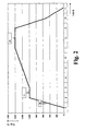
- Example 1 The prepared on the basis of Example 1 and dried slurry layer on the quartz glass flange is then under a pure hydrogen atmosphere using the in FIG. 2 glazed heating profiles shown in a sintering furnace.
- the heating profile includes an initially steep heating ramp, during which the slurry layer is heated from room temperature to a lower heating temperature of 1000 ° C within one hour. At the lower heating temperature, the slip layer is held for one hour and then heated to a top heating temperature of 1400 ° C over a second, flat heating ramp for four hours. The holding time at the upper heating temperature is in the embodiment two hours. Thereafter, the slip layer is completely vitrified, transparent and bubble-free.
- the subsequent cooling is carried out in the oven under hydrogen up to a temperature of 500 ° C with a controlled cooling rate of 15 ° C / min and then with further closed oven by free cooling.
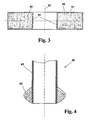
- FIG. 3 shows the thus coated quartz glass flange schematically based on a sectional view.
- the flange consists of an annular base body 30 made of transparent quartz glass, which is surrounded on all sides by a crack-free and transparent SiO 2 layer 31, which for reasons of representation in the FIG. 3 is shown exaggeratedly thick.
- the central axis is designated by the reference numeral 32.
- the SiO 2 layer 31 on the quartz glass flange base body 30 has an average layer thickness of 0.2 mm. It is characterized by a density which corresponds to that of quartz glass, and by high thermal shock resistance. As a result of its final treatment in the sintering furnace it shows a crack-free surfaces with a mean "natural" surface roughness (R a ) of about 1.2 microns, which exclusively - that is, without further post-processing - as a result of their preparation using a SiO 2 grain containing Schlickers results. On the surface, material layers adhere particularly well, resulting in an extension of the cleaning cycles compared to known quartz glass flanges and thus an extension of the service life.
- a uniform, closed slip layer is formed with a thickness of about 0.35 mm and dried as described above with reference to Example 1.
- the slip layer is then vitrified by means of a CO 2 laser, wherein the laser beam diameter was widened by means of optics to about 5 mm, and the laser beam was guided in a grid pattern over the distance to be glazed at a translation speed of 500 mm / min. The distance between the laser exit and the surface was kept constant at 300 mm.
- the bead-like thickened slip layer produced and dried using Example 2 at the end of the quartz glass tube is subsequently vitrified by means of a oxyhydrogen gas burner.
- the thickening is heated until a completely transparent, flame-polished and dense surface is obtained.
- FIG. 4 shows a section of the resulting quartz glass semi-finished product 40 by means of a sectional view.
- the semifinished product 40 is used to produce a spherical cut partly made of quartz glass.
- one end of the quartz glass tube 41 which has an outer diameter of 25 mm and a wall thickness of 2 mm, is provided with a glazed thickening 42 made of SiO 2 having a maximum thickness of 15 mm, which is produced as described above using an SiO 2 pore has been.
- the thickening 42 is finally mechanically processed and flame polished. It is characterized by freedom from cracks as well as a high density, which corresponds to that of quartz glass.
- a slurry layer is formed on a rod of transparent, synthetically produced quartz glass having a hydroxyl group content of 250 ppm by weight by immersion and then dried, as described in Example 1. After drying, the thickness of the slurry layer is 0.3 mm.
- the glazing is done in an oven under air, the heating profile corresponds to how it is in FIG. 2 shown and explained in more detail above with reference to Example 3, but with the difference that the holding time of two hours at the maximum temperature of 1400 ° C is omitted. The cooling starts immediately after this temperature is reached.
- the glazed SiO 2 glass mass thus obtained is surprisingly completely transparent. and it has a thickness of 0.2 mm on average and an average roughness R a of 1.2 ⁇ m.
- the dried slip layer produced on the basis of Example 6 on the quartz glass rod is introduced into a sintering furnace for vitrification and vitrified there in air.
- the heating profile is the same as in FIG. 2 is illustrated and explained in more detail above with reference to Example 3, with the difference that the maximum temperature is not 1400 ° C, but only 1050 ° C. At this temperature, the coated silica glass rod is held for 2 hours and then cooled.
- the resulting SiO 2 glass mass shows a high density of about 2.15 g / cm 3 , but is still substantially opaque.
- the opacity is shown by the fact that the direct spectral transmission in the wavelength range between 190 nm and 2650 nm is below 10%.
- An initial granule consisting of 95% by weight of SiO 2 and 5% by weight of Y 2 O 3 .
- pure quartz glass powder having an average particle diameter of about 200 ⁇ m is mixed with an yttrium oxide powder having an average particle size of about 5 ⁇ m, and the powder mixture is melted in an electric furnace under vacuum in a graphite mold.
- the yttria-doped quartz glass thus produced is comminuted and processed by wet milling, as described in Example 1, to give a homogeneous base slip having a solids content of 79%.
- Y 2 O 3 quartz glass grain size with a grain size of 5 microns, a solids content of 84 wt .-% is set.
- This mixture is further processed as described in Example 1, so that the resulting doped SiO 2 particles in the slurry show a particle size distribution which is characterized by a D 50 value of about 8 ⁇ m and by a D 90 value of about 40 ⁇ m ,
- a uniform, closed slip layer having a thickness of about 0.35 mm is formed on a flange and dried as described above in Example 1.
- the thus obtained slip layer is then vitrified to form a transparent, with 5 wt .-% Y 2 O 3 doped silica glass layer. It is characterized by a particularly high resistance to corrosive gas.
- a slurry of quartz glass grain 11 and water 12 is prepared as described above with reference to Example 1.
- finely divided Al 2 O 3 powder 16 in an amount of 500 ppm by weight (based on the SiO 2 content) is added to the slurry.
- This mixture 13 is ground in a drum mill to a homogeneous slurry 14, which has a solids content of 82%.
- the SiO 2 particles obtained in the slurry 14 after grinding show a particle size distribution with particle sizes in the range between 0.45 ⁇ m and 50 ⁇ m, with SiO 2 particles with particle sizes in the range between 1 ⁇ m and 10 ⁇ m making up the largest volume fraction (D 50 -Value).
- a green body 20 is produced from the homogeneous slip 14.
- the slurry 14 is poured into a tubular membrane mold of vacuum-formed silicone, which is embedded in carbon dioxide snow (dry ice). This causes a rapid freezing of the slurry 14 to a blue body 22 in the form of a rod with an outer diameter of 10 mm.
- the addition of glycerine contributes to a homogeneous structure which is free of iron needle structures.
- the shock-frozen blue body 22 is removed from the membrane mold and immediately - in the frozen state - placed in a pre-heated to 80 ° C convection oven and dried for several hours at this temperature. Continuous evaporation and removal of moisture from the surface will prevent recondensation of moisture and re-surface freezing, which would be associated with needle crystal formation and disruption of the green body structure.
- the dried green body 20 is then determined using the in FIG. 2 shown heating profiles in a furnace under pure hydrogen atmosphere sintered, wherein the holding time at the upper heating temperature four hours (instead of two hours).
Landscapes
- Chemical & Material Sciences (AREA)
- Engineering & Computer Science (AREA)
- Materials Engineering (AREA)
- Organic Chemistry (AREA)
- Geochemistry & Mineralogy (AREA)
- Life Sciences & Earth Sciences (AREA)
- Chemical Kinetics & Catalysis (AREA)
- General Chemical & Material Sciences (AREA)
- Manufacturing & Machinery (AREA)
- Dispersion Chemistry (AREA)
- Glass Melting And Manufacturing (AREA)
- Glass Compositions (AREA)
- Surface Treatment Of Glass (AREA)
Priority Applications (1)
| Application Number | Priority Date | Filing Date | Title |
|---|---|---|---|
| EP10182969.5A EP2263981B1 (de) | 2004-08-23 | 2005-08-23 | Verfahren zur Herstellung eines Quarzglasbauteils |
Applications Claiming Priority (3)
| Application Number | Priority Date | Filing Date | Title |
|---|---|---|---|
| DE102004040833 | 2004-08-23 | ||
| DE102004052312A DE102004052312A1 (de) | 2004-08-23 | 2004-10-28 | Beschichtetes Bauteil aus Quarzglas sowie Verfahren zur Herstellung des Bauteils |
| PCT/EP2005/009073 WO2006021415A2 (de) | 2004-08-23 | 2005-08-23 | Beschichtetes bauteil aus quarzglas sowie verfahren zur herstellung des bauteils |
Related Child Applications (2)
| Application Number | Title | Priority Date | Filing Date |
|---|---|---|---|
| EP10182969.5A Division-Into EP2263981B1 (de) | 2004-08-23 | 2005-08-23 | Verfahren zur Herstellung eines Quarzglasbauteils |
| EP10182969.5A Division EP2263981B1 (de) | 2004-08-23 | 2005-08-23 | Verfahren zur Herstellung eines Quarzglasbauteils |
Publications (2)
| Publication Number | Publication Date |
|---|---|
| EP1789370A2 EP1789370A2 (de) | 2007-05-30 |
| EP1789370B1 true EP1789370B1 (de) | 2014-01-15 |
Family
ID=35355640
Family Applications (2)
| Application Number | Title | Priority Date | Filing Date |
|---|---|---|---|
| EP05781997.1A Expired - Lifetime EP1789370B1 (de) | 2004-08-23 | 2005-08-23 | Beschichtetes bauteil aus quarzglas sowie verfahren zur herstellung des bauteils |
| EP10182969.5A Expired - Lifetime EP2263981B1 (de) | 2004-08-23 | 2005-08-23 | Verfahren zur Herstellung eines Quarzglasbauteils |
Family Applications After (1)
| Application Number | Title | Priority Date | Filing Date |
|---|---|---|---|
| EP10182969.5A Expired - Lifetime EP2263981B1 (de) | 2004-08-23 | 2005-08-23 | Verfahren zur Herstellung eines Quarzglasbauteils |
Country Status (5)
| Country | Link |
|---|---|
| US (1) | US20080075949A1 (enExample) |
| EP (2) | EP1789370B1 (enExample) |
| JP (1) | JP2008510676A (enExample) |
| DE (1) | DE102004052312A1 (enExample) |
| WO (1) | WO2006021415A2 (enExample) |
Families Citing this family (29)
| Publication number | Priority date | Publication date | Assignee | Title |
|---|---|---|---|---|
| JP5050363B2 (ja) * | 2005-08-12 | 2012-10-17 | 株式会社Sumco | 半導体シリコン基板用熱処理治具およびその製作方法 |
| JP2007261875A (ja) * | 2006-03-28 | 2007-10-11 | Tosoh Quartz Corp | 表面に粗面化層を形成した石英ガラス部材 |
| DE102006043738B4 (de) * | 2006-09-13 | 2008-10-16 | Heraeus Quarzglas Gmbh & Co. Kg | Bauteil aus Quarzglas zum Einsatz bei der Halbleiterfertigung und Verfahren zur Herstellung desselben |
| DE102006052512A1 (de) * | 2006-11-06 | 2008-05-08 | Heraeus Quarzglas Gmbh & Co. Kg | Verfahren zur Herstellung von opakem Quarzglas, nach dem Verfahren erhaltenes Halbzeug sowie daraus hergestelltes Bauteil |
| DE102006062166B4 (de) | 2006-12-22 | 2009-05-14 | Heraeus Quarzglas Gmbh & Co. Kg | Quarzglas-Bauteil mit Reflektorschicht sowie Verfahren zur Herstellung desselben |
| DE102007008696B3 (de) * | 2007-02-20 | 2008-10-02 | Heraeus Noblelight Gmbh | Infrarotstrahler mit opakem Reflektor und seine Herstellung |
| DE102007017004A1 (de) * | 2007-02-27 | 2008-08-28 | Heraeus Quarzglas Gmbh & Co. Kg | Optisches Bauteil aus synthetischem Quarzglas mit erhöhter Strahlenbeständigkeit, sowie Verfahren zur Herstellung des Bauteils |
| US7718559B2 (en) * | 2007-04-20 | 2010-05-18 | Applied Materials, Inc. | Erosion resistance enhanced quartz used in plasma etch chamber |
| DE102007030698B4 (de) | 2007-06-30 | 2009-06-10 | Heraeus Quarzglas Gmbh & Co. Kg | Verfahren zur Herstellung eines Verbundkörpers aus einem Basiskörper aus opakem Quarzglas und einer dichten Versiegelungsschicht sowie Verwendung des Verbundkörpers |
| US20090308315A1 (en) * | 2008-06-13 | 2009-12-17 | Asm International N.V. | Semiconductor processing apparatus with improved thermal characteristics and method for providing the same |
| DE102008049325B4 (de) * | 2008-09-29 | 2011-08-25 | Heraeus Quarzglas GmbH & Co. KG, 63450 | Verfahren zur Herstellung eines rohrförmigen Halbzeugs aus Quarzglas sowie Halbzeug aus Quarzglas |
| JP5402391B2 (ja) * | 2009-01-27 | 2014-01-29 | 信越化学工業株式会社 | 半導体用合成石英ガラス基板の加工方法 |
| KR20150041610A (ko) * | 2012-07-18 | 2015-04-16 | 호야 가부시키가이샤 | 유리 성형품 및 그 제조 방법, 광학 소자 블랭크, 그리고 광학 소자 및 그 제조 방법 |
| DE102012109930A1 (de) * | 2012-10-18 | 2014-04-24 | Heraeus Noblelight Gmbh | Strahlereinheit zur Erzeugung ultravioletter Strahlung sowie Verfahren zu deren Herstellung |
| SG11201508512PA (en) * | 2013-05-23 | 2015-12-30 | Applied Materials Inc | A coated liner assembly for a semiconductor processing chamber |
| US9296614B1 (en) * | 2014-11-12 | 2016-03-29 | Corning Incorporated | Substrate such as for use with carbon nanotubes |
| EP3173386B1 (de) * | 2015-11-25 | 2018-05-02 | Heraeus Quarzglas GmbH & Co. KG | Verfahren zur herstellung eines verbundkörpers aus hochkieselsäurehaltigem werkstoff |
| CN108698894A (zh) | 2015-12-18 | 2018-10-23 | 贺利氏石英玻璃有限两合公司 | 在多腔式烘箱中制备石英玻璃体 |
| WO2017103131A1 (de) | 2015-12-18 | 2017-06-22 | Heraeus Quarzglas Gmbh & Co. Kg | Verringern des erdalkalimetallgehalts von siliziumdioxidgranulat durch behandlung von kohlenstoffdotiertem siliziumdioxidgranulat bei hoher temperatur |
| TWI733723B (zh) | 2015-12-18 | 2021-07-21 | 德商何瑞斯廓格拉斯公司 | 不透明石英玻璃體的製備 |
| KR20180094087A (ko) | 2015-12-18 | 2018-08-22 | 헤래우스 크바르츠글라스 게엠베하 & 컴파니 케이지 | 실리카 과립으로부터 실리카 유리 제품의 제조 |
| CN108698883A (zh) | 2015-12-18 | 2018-10-23 | 贺利氏石英玻璃有限两合公司 | 石英玻璃制备中的二氧化硅的喷雾造粒 |
| JP6940235B2 (ja) | 2015-12-18 | 2021-09-22 | ヘレウス クワルツグラス ゲーエムベーハー ウント コンパニー カーゲー | 高融点金属の溶融坩堝内での石英ガラス体の調製 |
| EP3390303B1 (de) | 2015-12-18 | 2024-02-07 | Heraeus Quarzglas GmbH & Co. KG | Herstellung von quarzglaskörpern mit taupunktkontrolle im schmelzofen |
| WO2017103153A1 (de) | 2015-12-18 | 2017-06-22 | Heraeus Quarzglas Gmbh & Co. Kg | Glasfasern und vorformen aus quarzglas mit geringem oh-, cl- und al-gehalt |
| CN109153593A (zh) | 2015-12-18 | 2019-01-04 | 贺利氏石英玻璃有限两合公司 | 合成石英玻璃粉粒的制备 |
| KR20180095619A (ko) | 2015-12-18 | 2018-08-27 | 헤래우스 크바르츠글라스 게엠베하 & 컴파니 케이지 | 실리카 유리 제조 동안 규소 함량의 증가 |
| EP3428132B1 (de) | 2017-07-10 | 2023-08-30 | Heraeus Quarzglas GmbH & Co. KG | Quarzglasbauteil mit hoher thermischer stabilität, halbzeug dafür und verfahren zur herstellung desselben |
| JP7162491B2 (ja) * | 2018-10-17 | 2022-10-28 | 信越石英株式会社 | 多層構造シリカガラス体の製造方法 |
Family Cites Families (19)
| Publication number | Priority date | Publication date | Assignee | Title |
|---|---|---|---|---|
| US2976171A (en) * | 1957-10-14 | 1961-03-21 | Smith Corp A O | Glass coated steel structure and method of making the same |
| US3972704A (en) * | 1971-04-19 | 1976-08-03 | Sherwood Refractories, Inc. | Apparatus for making vitreous silica receptacles |
| US5045751A (en) * | 1988-10-25 | 1991-09-03 | Asahi Glass Company Ltd. | Cathode ray tube of improved breakdown voltage characteristic |
| EP0367269A3 (en) * | 1988-11-04 | 1991-11-13 | Asahi Glass Company Ltd. | Method for reinforcing glass, film-forming composition for the reinforcement of glass and reinforced glass articles |
| AU632240B2 (en) * | 1990-08-27 | 1992-12-17 | Furukawa Electric Co. Ltd., The | Method for manufacturing a silica glass base material |
| JPH04124044A (ja) * | 1990-09-15 | 1992-04-24 | Furukawa Electric Co Ltd:The | 石英系ガラス母材の製造方法 |
| DE4338807C1 (de) * | 1993-11-12 | 1995-01-26 | Heraeus Quarzglas | Formkörper mit hohem Gehalt an Siliziumdioxid und Verfahren zur Herstellung solcher Formkörper |
| DE4417405A1 (de) * | 1994-05-18 | 1995-11-23 | Inst Neue Mat Gemein Gmbh | Verfahren zur Herstellung von strukturierten anorganischen Schichten |
| US6355587B1 (en) * | 1994-06-30 | 2002-03-12 | Ted A. Loxley | Quartz glass products and methods for making same |
| GB9722020D0 (en) | 1997-10-17 | 1997-12-17 | Tsl Group Plc | Production of quartz glass articles having high surface purity |
| US6248671B1 (en) * | 1998-08-19 | 2001-06-19 | Micron Technology, Inc. | Semiconductor processing apparatuses, and methods of forming antireflective coating materials over substrates |
| JP2000086251A (ja) * | 1998-09-17 | 2000-03-28 | Ushio Inc | 焼結石英ガラス成形体の焼結方法 |
| JP3837942B2 (ja) * | 1998-09-28 | 2006-10-25 | ウシオ電機株式会社 | 焼結石英ガラス成形体の製造方法 |
| JP2001163629A (ja) * | 1999-12-08 | 2001-06-19 | Toshiba Ceramics Co Ltd | 半導体処理炉用断熱体とその製造方法 |
| DE19962451C1 (de) * | 1999-12-22 | 2001-08-30 | Heraeus Quarzglas | Verfahren für die Herstellung von opakem Quarzglas und für die Durchführung des Verfahrens geeignetes Si0¶2¶-Granulat |
| DE10163939A1 (de) * | 2001-12-22 | 2003-07-10 | Degussa | Schicht erhalten aus einer wässerigen Dispersion enthaltend flammenhydrolytisch hergestelltes Silicium-Titan-Mischoxidpulver |
| DE10243954B3 (de) * | 2002-09-20 | 2004-07-08 | Heraeus Quarzglas Gmbh & Co. Kg | Verfahren für die Herstellung eines opaken Quarzglas-Kompositwerkstoffs sowie Verwendung desselben |
| JP4444559B2 (ja) * | 2002-10-09 | 2010-03-31 | ジャパンスーパークォーツ株式会社 | 石英ガラスルツボの強化方法とシリコン単結晶の引き上げ方法 |
| DE102004038602B3 (de) * | 2004-08-07 | 2005-12-29 | Heraeus Quarzglas Gmbh & Co. Kg | Elektrogeschmolzenes, synthetisches Quarzglas, insbesondere für den Einsatz in der Lampen- und in der Halbleiterfertigung und Verfahren zur Herstellung desselben |
-
2004
- 2004-10-28 DE DE102004052312A patent/DE102004052312A1/de not_active Withdrawn
-
2005
- 2005-08-23 JP JP2007528725A patent/JP2008510676A/ja active Pending
- 2005-08-23 WO PCT/EP2005/009073 patent/WO2006021415A2/de not_active Ceased
- 2005-08-23 EP EP05781997.1A patent/EP1789370B1/de not_active Expired - Lifetime
- 2005-08-23 EP EP10182969.5A patent/EP2263981B1/de not_active Expired - Lifetime
- 2005-08-23 US US11/661,160 patent/US20080075949A1/en not_active Abandoned
Also Published As
| Publication number | Publication date |
|---|---|
| US20080075949A1 (en) | 2008-03-27 |
| WO2006021415A2 (de) | 2006-03-02 |
| EP2263981A2 (de) | 2010-12-22 |
| EP1789370A2 (de) | 2007-05-30 |
| DE102004052312A1 (de) | 2006-03-02 |
| WO2006021415A3 (de) | 2006-10-26 |
| EP2263981A3 (de) | 2013-09-04 |
| JP2008510676A (ja) | 2008-04-10 |
| EP2263981B1 (de) | 2014-10-01 |
Similar Documents
| Publication | Publication Date | Title |
|---|---|---|
| EP1789370B1 (de) | Beschichtetes bauteil aus quarzglas sowie verfahren zur herstellung des bauteils | |
| EP0920543B1 (de) | Quarzglas-bauteil für ein reaktorgehäuse sowie herstellungsverfahren und anwendung dafür | |
| DE4338807C1 (de) | Formkörper mit hohem Gehalt an Siliziumdioxid und Verfahren zur Herstellung solcher Formkörper | |
| DE102004051846B4 (de) | Bauteil mit einer Reflektorschicht sowie Verfahren für seine Herstellung | |
| DE19962449C2 (de) | Quarzglastiegel und Verfahren für seine Herstellung | |
| EP2878584B1 (de) | Verfahren zur Herstellung eines beschichteten Bauteils aus Quarzglas oder Quarzgut | |
| EP2069244B1 (de) | SiO2-SCHLICKER FÜR DIE HERSTELLUNG VON QUARZGLAS SOWIE VERWENDUNG DES SCHLICKERS | |
| EP2173673B1 (de) | Verfahren zur herstellung eines verbundkörpers aus einem basiskörper aus opakem quarzglas und einer dichten versiegelungsschicht | |
| EP2485988B1 (de) | Verfahren zur herstellung eines beschichteten bauteils aus quarzglas | |
| DE3228008A1 (de) | Herstellung gesinterter glaeser mit hohem siliciumoxidanteil | |
| DE3001792A1 (de) | Verfahren zur herstellung eines mutterstabs fuer die herstellung von optischen fasern | |
| DE102004054392A1 (de) | Verfahren zum Verbinden von Bauteilen aus hochkieselsäurehaltigem Werkstoff, sowie aus derartigen Bauteilen zusammengefügter Bauteil-Verbund | |
| EP1791796B1 (de) | Verfahren zum verbinden von bauteilen aus hochkieselsäurehaltigem werkstoff unter einsatz eines fügemittels, sowie nach dem verfahren erhaltener bauteil-verbund | |
| EP2102125A1 (de) | Quarzglas-bauteil mit reflektorschicht sowie verfahren zur herstellung desselben | |
| DE112013007710B4 (de) | Verfahren zum Formen von Komponenten aus opakem Quarzglas | |
| DE10156137B4 (de) | Verfahren zur Herstellung eines Kieselglastiegels mit kristallinen Bereichen aus einem porösen Kieselglasgrünkörper | |
| EP3052448B1 (de) | Spiegelblank für euv lithographie ohne ausdehnung unter euv-bestrahlung | |
| WO2005026067A1 (de) | VERFAHREN ZUR HERSTELLUNG EINES Si3N4 BESCHICHTETEN SiO2-FORMKÖRPERS | |
| DE2827303C2 (de) | Verfahren zur Herstellung eines Glasgegenstandes und dessen Anwendung | |
| DE10218864C1 (de) | Verfahren zur Herstellung eines zylinderförmigen Quarzglaskörpers mit geringem OH-Gehalt | |
| DE102006024831B4 (de) | Verfahren zur Herstellung eines Halbzeugs aus synthetischem Quarzglas | |
| DE3623843A1 (de) | Verfahren zur herstellung von quarzglas | |
| DE102005058819A1 (de) | Verfahren zur Beschichtung eines Bauteils aus hochkieselsäurehaltigem Glas sowie mit einer SiO2-haltigen, glasigen Schicht versehenes Bauteil | |
| EP2982780B1 (de) | Verfahren zur herstellung eines siliziumblocks, zur verfahrensdurchführung geeignete kokille aus quarzglas oder quarzgut sowie verfahren für deren herstellung | |
| DE102005059291B4 (de) | Verfahren für die Herstellung eines Quarzglas-Bauteils |
Legal Events
| Date | Code | Title | Description |
|---|---|---|---|
| PUAI | Public reference made under article 153(3) epc to a published international application that has entered the european phase |
Free format text: ORIGINAL CODE: 0009012 |
|
| 17P | Request for examination filed |
Effective date: 20070222 |
|
| AK | Designated contracting states |
Kind code of ref document: A2 Designated state(s): AT BE BG CH CY LI |
|
| DAX | Request for extension of the european patent (deleted) | ||
| RBV | Designated contracting states (corrected) |
Designated state(s): AT BE BG CH CY LI |
|
| 17Q | First examination report despatched |
Effective date: 20080725 |
|
| GRAP | Despatch of communication of intention to grant a patent |
Free format text: ORIGINAL CODE: EPIDOSNIGR1 |
|
| INTG | Intention to grant announced |
Effective date: 20130821 |
|
| RBV | Designated contracting states (corrected) |
Designated state(s): DE FR GB IT NL |
|
| GRAS | Grant fee paid |
Free format text: ORIGINAL CODE: EPIDOSNIGR3 |
|
| GRAA | (expected) grant |
Free format text: ORIGINAL CODE: 0009210 |
|
| AK | Designated contracting states |
Kind code of ref document: B1 Designated state(s): DE FR GB IT NL |
|
| REG | Reference to a national code |
Ref country code: GB Ref legal event code: FG4D Free format text: NOT ENGLISH |
|
| REG | Reference to a national code |
Ref country code: DE Ref legal event code: R096 Ref document number: 502005014182 Country of ref document: DE Effective date: 20140227 |
|
| REG | Reference to a national code |
Ref country code: NL Ref legal event code: T3 |
|
| REG | Reference to a national code |
Ref country code: DE Ref legal event code: R097 Ref document number: 502005014182 Country of ref document: DE |
|
| PLBE | No opposition filed within time limit |
Free format text: ORIGINAL CODE: 0009261 |
|
| STAA | Information on the status of an ep patent application or granted ep patent |
Free format text: STATUS: NO OPPOSITION FILED WITHIN TIME LIMIT |
|
| 26N | No opposition filed |
Effective date: 20141016 |
|
| REG | Reference to a national code |
Ref country code: DE Ref legal event code: R097 Ref document number: 502005014182 Country of ref document: DE Effective date: 20141016 |
|
| REG | Reference to a national code |
Ref country code: FR Ref legal event code: PLFP Year of fee payment: 12 |
|
| REG | Reference to a national code |
Ref country code: FR Ref legal event code: PLFP Year of fee payment: 13 |
|
| REG | Reference to a national code |
Ref country code: FR Ref legal event code: PLFP Year of fee payment: 14 |
|
| P01 | Opt-out of the competence of the unified patent court (upc) registered |
Effective date: 20230530 |
|
| PGFP | Annual fee paid to national office [announced via postgrant information from national office to epo] |
Ref country code: NL Payment date: 20240821 Year of fee payment: 20 |
|
| PGFP | Annual fee paid to national office [announced via postgrant information from national office to epo] |
Ref country code: DE Payment date: 20240821 Year of fee payment: 20 |
|
| PGFP | Annual fee paid to national office [announced via postgrant information from national office to epo] |
Ref country code: GB Payment date: 20240823 Year of fee payment: 20 |
|
| PGFP | Annual fee paid to national office [announced via postgrant information from national office to epo] |
Ref country code: FR Payment date: 20240828 Year of fee payment: 20 |
|
| PGFP | Annual fee paid to national office [announced via postgrant information from national office to epo] |
Ref country code: IT Payment date: 20240827 Year of fee payment: 20 |
|
| REG | Reference to a national code |
Ref country code: DE Ref legal event code: R082 Ref document number: 502005014182 Country of ref document: DE Representative=s name: BRAND, NORMEN, DR. RER. NAT., DE |
|
| REG | Reference to a national code |
Ref country code: DE Ref legal event code: R071 Ref document number: 502005014182 Country of ref document: DE |
|
| REG | Reference to a national code |
Ref country code: NL Ref legal event code: MK Effective date: 20250822 |