EP1781450B1 - Actionneur - Google Patents
Actionneur Download PDFInfo
- Publication number
- EP1781450B1 EP1781450B1 EP05762143A EP05762143A EP1781450B1 EP 1781450 B1 EP1781450 B1 EP 1781450B1 EP 05762143 A EP05762143 A EP 05762143A EP 05762143 A EP05762143 A EP 05762143A EP 1781450 B1 EP1781450 B1 EP 1781450B1
- Authority
- EP
- European Patent Office
- Prior art keywords
- drive
- pulley
- pulleys
- driven
- guide
- Prior art date
- Legal status (The legal status is an assumption and is not a legal conclusion. Google has not performed a legal analysis and makes no representation as to the accuracy of the status listed.)
- Active
Links
Images

Classifications
-
- B—PERFORMING OPERATIONS; TRANSPORTING
- B25—HAND TOOLS; PORTABLE POWER-DRIVEN TOOLS; MANIPULATORS
- B25J—MANIPULATORS; CHAMBERS PROVIDED WITH MANIPULATION DEVICES
- B25J9/00—Programme-controlled manipulators
- B25J9/10—Programme-controlled manipulators characterised by positioning means for manipulator elements
-
- F—MECHANICAL ENGINEERING; LIGHTING; HEATING; WEAPONS; BLASTING
- F16—ENGINEERING ELEMENTS AND UNITS; GENERAL MEASURES FOR PRODUCING AND MAINTAINING EFFECTIVE FUNCTIONING OF MACHINES OR INSTALLATIONS; THERMAL INSULATION IN GENERAL
- F16H—GEARING
- F16H19/00—Gearings comprising essentially only toothed gears or friction members and not capable of conveying indefinitely-continuing rotary motion
- F16H19/02—Gearings comprising essentially only toothed gears or friction members and not capable of conveying indefinitely-continuing rotary motion for interconverting rotary or oscillating motion and reciprocating motion
- F16H19/06—Gearings comprising essentially only toothed gears or friction members and not capable of conveying indefinitely-continuing rotary motion for interconverting rotary or oscillating motion and reciprocating motion comprising flexible members, e.g. an endless flexible member
- F16H2019/0609—Gearings comprising essentially only toothed gears or friction members and not capable of conveying indefinitely-continuing rotary motion for interconverting rotary or oscillating motion and reciprocating motion comprising flexible members, e.g. an endless flexible member the reciprocating motion being created by at least one drum or pulley with different diameters, using a differential effect
-
- Y—GENERAL TAGGING OF NEW TECHNOLOGICAL DEVELOPMENTS; GENERAL TAGGING OF CROSS-SECTIONAL TECHNOLOGIES SPANNING OVER SEVERAL SECTIONS OF THE IPC; TECHNICAL SUBJECTS COVERED BY FORMER USPC CROSS-REFERENCE ART COLLECTIONS [XRACs] AND DIGESTS
- Y10—TECHNICAL SUBJECTS COVERED BY FORMER USPC
- Y10T—TECHNICAL SUBJECTS COVERED BY FORMER US CLASSIFICATION
- Y10T74/00—Machine element or mechanism
- Y10T74/18—Mechanical movements
- Y10T74/1836—Rotary to rotary
-
- Y—GENERAL TAGGING OF NEW TECHNOLOGICAL DEVELOPMENTS; GENERAL TAGGING OF CROSS-SECTIONAL TECHNOLOGIES SPANNING OVER SEVERAL SECTIONS OF THE IPC; TECHNICAL SUBJECTS COVERED BY FORMER USPC CROSS-REFERENCE ART COLLECTIONS [XRACs] AND DIGESTS
- Y10—TECHNICAL SUBJECTS COVERED BY FORMER USPC
- Y10T—TECHNICAL SUBJECTS COVERED BY FORMER US CLASSIFICATION
- Y10T74/00—Machine element or mechanism
- Y10T74/18—Mechanical movements
- Y10T74/18568—Reciprocating or oscillating to or from alternating rotary
- Y10T74/18832—Reciprocating or oscillating to or from alternating rotary including flexible drive connector [e.g., belt, chain, strand, etc.]
- Y10T74/18848—Reciprocating or oscillating to or from alternating rotary including flexible drive connector [e.g., belt, chain, strand, etc.] with pulley
Definitions
- This invention relates to an actuator and has particular reference to linear and rotary actuators, particularly those for use in the control of robotic arms.
- the present invention relates to an actuator according to the preamble of claim 1.
- an actuator is known eg from JP-A-02 199 345 .
- actuators for the control wires of robotic arms have been of the capstan type. These comprise a motor driving a windup capstan around which the control wire is wrapped. Operation of the motor drives the capstan and causes or allows corresponding movement of the wire. These capstan drives are relatively bulky, and furthermore tend to produce stretching and slippage of the wire about the capstan thus rendering precision of control more difficult. In order to overcome this problem, it is frequently the case that the control mechanism and motor drives for each control are spaced from the base or datum of the robotic arm thus resulting in a relatively large and bulky control assembly for the arm.
- linear actuators have been produced having a movable carriage to which the control wire is attached and the whole is mounted upon a screw or worm so the rotation of the screw or worm results in movement of the carriage.
- a disadvantage of this arrangement is the relative weight of the assembly and the inevitable backlash in the worm or screw arrangement. Furthermore, such arrangements tend to have relatively high frictional forces and the mechanical advantage achievable is effectively that of an inclined plane defined by the pitch of the screw.
- the speed categories are slow (say 0-25 mm per second), medium (say 25-500 mm per second) and high (>500 mm per second).
- the precision categories can be defined as zero precision (absolute positioning not required and backlash unimportant), low precision (positioning required but low accuracy and some backlash acceptable say 0.25-3 mm) and high precision (where accurate positioning and zero/low backlash is required - say 0.001-0.25 mm).
- Such actuators are often powered by rotary electric motors; although direct drive linear actuators are available, they are costly to build and control.
- the linear actuator is powered by a rotary electric motor
- several design options are available to produce the linear motion, these include belt drives, lead screws, ball screws, and rack and pinion mechanisms.
- a gearbox will be required between the motor and the linear motion converter in order to match the motor speed (typically 3000-6000 rpm) to the required pulley/pinion/ ball-screw speed.
- the gearbox adds considerably to the cost, particularly if high precision is required as in a zero/low backlash environment as the gearbox must be at least as accurate as the motor and the linear motion converter.
- JP-A-02 199 345 discloses an actuator having an endless drive belt which is looped around two drive pulleys, two driven pulleys and two guide pulleys, the driven pulleys being mounted upon a movable carriage.
- the pulleys all lie in the same plane, and the axes of rotation of all of the pulleys are parallel.
- a second drive belt communicates drive between the two drive pulleys, and the mounting of the second drive belt is such that the circumferential speed of the two drive pulleys is slightly different, the difference in circumferential speeds causing the carriage to move.
- EP-A-0 161 431 discloses several actuators, all of which share the features of the Japanese patent application set out above. Certain of the actuators include additional guide pulleys.
- US-A-6,134,978 discloses in Figs. 3A,4A, Fig. 5 and Fig. 6 several actuators which are very similar to the actuators of the above Japanese patent document, except that in Figs. 3A,4A and 5 a gear wheel is used in place of the second drive belt to communicate drive between the two drive pulleys, and in Fig.6 a second and third drive belt communicate drive to the respective drive pulleys.
- the actuator of Figs. 3B,4B of this document is somewhat similar to that of Figs. 3A,4A except that the two driven pulleys are co-axial and lie to either side of the plane containing the drive pulleys and the guide pulleys.
- the above prior art documents relate to actuators having a drive belt to generate motion using a harmonic principle.
- the required motion is generated by virtue of the different circumferential speeds of the two drive pulleys. This reduces or eliminates the need for a gearbox between the motor and the drive pulley for low and medium speed applications.
- a drive is substantially backlash free thereby allowing a high precision drive at relatively low cost.
- the object of the present invention is to provide a more compact and less complex actuator.
- drive belt is also used in the claims and preamble, but unless otherwise indicated the term “belt” should be understood to encompass any suitable continuous or endless drive member such as a chain, cable, wire or the like.
- pulley is used in the following specific description throughout, as it is common to use pulleys with a drive belt, but the term “pulley” should be understood to encompass gears and sprockets as well as toothed or untoothed wheels and rollers, or the like.
- the circumferential speeds can differ because of the drive pulleys having different circumferential lengths.
- the drive belt may be toothed, and in such embodiments at least the drive pulleys are preferably toothed to engage with the belt.
- the actuator can be a linear actuator, preferably having a carriage mounted for linear movement.
- actuators also include one or more guide pulleys which are also engaged by the endless drive belt and serve to guide and/or redirect the drive belt between the drive and driven pulleys.
- a control line can be connected to the driven member, movement of the driven member causing corresponding movement of the control line.
- the control line can be connected to a robotic arm, for example.
- the motor may be an electric motor.
- the electric motor may drive the drive pulleys via a worm and wheel assembly thus providing additional mechanical advantage.
- the drive belt is always flexed in one direction around the various pulleys, i.e. preferably towards the teeth in embodiments of belt having teeth.
- the drive belt can be flexed in both directions, i.e. both towards the teeth and away from the teeth as it passes around the various pulleys, so that the belt teeth face outwards as they pass around some of the pulleys.
- the flexing of the belt in both directions is described herein as contraflexure drive.
- the path of the drive belt between the drive pulleys, the driven pulleys and the guide pulleys (if present) respectively is orientated by means of an angled pulley.
- the size and angle of the pulley is chosen so that the central axis of the drive belt fibres is substantially co-axial between the respective pulleys. This means that the drive belt is twisted along this axis with little or no translation or lateral movement, thus minimising stress variation across the belt fibres.
- Linear actuators in accordance with the present invention have been found to be particularly useful in the control of robotic arms of the type described in international application no. WO2002/016995 .
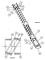
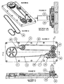
- the actuator illustrated generally at 10 comprises a longitudinal, channel shaped housing 11 having, at a first end 12, a motor and control assembly indicated generally at 14, and having at a second end 13, a control wire guide 15 (see Fig. 7 )
- the motor and control assembly 14 comprises a worm block 16 the base 17 of which is secured to the base of the channel shaped housing 11 at first end 12.
- the rear face 9 of worm block 16 carries an electric motor 19, which through coupling 7 ( Figure 5 ) turns the drive shaft 20 which projects through said rear face 9 and terminates in a drive worm 21 (see Figures 5 and 10 ).
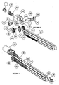
- the front face of the worm block 16 is cut away to provide a front opening 31 ( Figure 10 ).
- the sidewalls 23 of worm block 16 each carry a circular opening to provide a transverse bore 24, each of said openings accommodating a respective bearing 25.
- Each bearing 25 is adapted to receive for rotation therein an axle 26 having mounted thereon and for rotation therewith a worm wheel 27, a first drive pulley 28 and a second drive pulley 29.
- the worm wheel 27, first drive pulley 28 and second drive pulley 29 are formed as a unit; it will be appreciated that the first drive pulley 28 and the second drive pulley 29 may be formed as independent components each of which may be keyed to worm wheel 27 for rotation therewith by means well-known in the art, or as shown in this embodiment be joined by pin 8.
- the worm wheel and pulleys assembly is provided with shims and washers 34 for appropriate location of the worm wheel 27 and its associated first and second drive pulleys 28 and 29 relative to the front opening 31.
- Each of the first drive pulley 28 and the second drive pulley 29 are provided with respective teeth 32.
- the radius and therefore the circumferential length of the second drive pulley 29 is greater than that of the first drive pulley 29, so that the second drive pulley 29 is provided with one more tooth than the first drive pulley 28 (in other embodiments the drive pulleys can differ in circumferential length by more than one tooth).
- Each of the drive pulleys 28 and 29 is adapted to receive a wrap of an endless drive belt 40.
- Drive belt 40 is an endless or continuous belt which in this embodiment is of generally rectangular shaped cross-section having teeth on the inner surface thereof. Each of said teeth is adapted to engage corresponding teeth 32 on pulleys 28 and 29 respectively.
- the fixings for worm block 16 also secure a rearward extension 35 to housing 11 which extension 35 carries a printed circuit board 36 through which electric motor 19 is controlled.
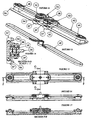
- the second end 13 of housing 11 also carries a pulley assembly indicated generally at 45 (see Figure 3 ).
- the pulley assembly 45 is associated with control wire guide indicated generally at 15 ( Figure 7 ).
- the assembly 45 is supported by slots 46 ( Figure 1 ) in housing 11 which slots carry a transverse axle 47 ( Figures 1 and 7 ) which in turn carries, for rotation thereon, guide pulleys 48 and 49 respectively.
- Each of guide pulleys 48 and 49 is adapted to accept a wrap of belt 40 and each of guide pulleys 48 and 49 is independently rotatable on transverse axle 47.
- the position of the axle 47 is maintained in slots 46 by the tension in drive belt 40.
- the drive belt tension is set during assembly by virtue of ramps 6 acting on bearings 25 in housing 11 (see Figure 4 ).
- a support piece for axle 47 may be releasably secured to the housing and means provided for biasing the support piece away from the motor and control assembly 14 for the purpose of tensioning the drive belt 40.
- Driven member or carriage 50 comprises a longitudinal member at 51 having a pair of longitudinally spaced driven pulleys 52 and 53 mounted for rotation with respect thereto.
- a forward extension 54 of longitudinal member 51 carries connecting means of generally known type for connecting a control wire 55 to the carriage by wrapping control wire 55 around helix 59 and securing with clamp 60 (see Figure 9 ).
- control wire 55 extends from the carriage 50 through guide hole 56 provided in the cylindrical surface of axle 47 and about an idler wheel 57 to exit the housing 11 by means of opening 58.
- the arrangement is such that movement of carriage 50 generally along the longitudinal axis of housing 11 results in corresponding movement of control wire 55.
- the drive belt 40 is configured generally as shown in Figures 10 and 11 .
- the drive belt passes from the first drive pulley 28 to the first driven pulley 52, from the first driven pulley 52 to the second drive pulley 29, from the second drive pulley 29 to the first guide pulley 48, from the first guide pulley 48 to the second driven pulley 53, from the second driven pulley 53 to the second guide pulley 49, and from the second guide pulley 49 back to the first drive pulley 28.
- the drive belt 40 defines a first loop between the first driven pulley 52 and the drive pulleys 28,29, and a second loop between the second driven pulley 53 and the guide pulleys 48,49, rotation of the drive pulleys 28,29 in a first direction causing an increase in the length of the first loop and a corresponding decrease in the length of the second loop.
- the axis of rotation of the first driven pulley 52 is angled with respect to the (common) axis of rotation of the drive pulleys 28 and 29. This allows the path of the drive belt 40 to be aligned with both of the drive pulley 28 and the drive pulley 29 without requiring lateral movement or deformation of the belt.
- the driven pulley 52 is positioned and sized such that the central axis 90 of the drive belt 40, i.e. the central axis of the longitudinal fibres of the drive belt, at the point at which the drive belt joins and leaves the driven pulley 52, is precisely aligned with the central axis 90 of the drive belt 40 at the point at which the belt leaves or joins the drive pulleys 28 and 29 respectively.
- the belt 40 is caused to twist as it moves between a drive pulley 28,29 and the driven pulley 52, but that the twist is effected about the central axis 90 of the belt fibres.
- a drive belt of this type is less likely to suffer damage or deterioration if it is twisted about its central axis, than would be the case if it was twisted about some other axis, and/or is required to move or deform laterally.
- the driven pulley aligns the path of the drive belt precisely with the drive pulleys, nor that the central axis of the drive belt as it leaves or joins the driven pulley is precisely aligned with the central axis of the belt as it joins or leaves a drive pulley, but the greater the misalignment the greater the likelihood of damage and deterioration of the belt, so that substantial alignment is preferred and precise alignment is ideal.
- the relationship between the driven pulley 53 and the guide pulleys 48, 49 is the same as that shown in Fig.2 so that the drive belt 40 only undergoes twisting movement, about its central axis, during its whole path of movement, regardless of the position of the carriage 50. Whilst this ideal relationship between the pulleys is specifically described for the embodiment of Figures 1-11 , the relationship between the pulleys in the other embodiments shown in the Figures is similarly ideal, though in those embodiments also the pulleys could be substantially aligned rather than precisely aligned, if desired.
- Operation of the motor 19 causes rotation of the drive worm gear 21.
- Drive worm gear 21 engages worm wheel 27 and transmits rotation to each of drive pulleys 28 and 29. Since drive pulley 29 is provided with one more tooth then drive pulley 28, rotation of each pulley by one complete revolution will ensure that the part of the drive belt 40 which is wrapped around pulley 29 will advance further than the part of the drive belt 40 which is wrapped around pulley 28, by the pitch of one tooth. This will result in an increase in the length of the first loop of the belt (between the drive pulleys and the driven pulley 52) by the pitch of the teeth and a corresponding increase in the distance between the drive pulleys 28,29 and the carriage 50 by half the pitch of the teeth.
- the linear displacement of the carriage 50 per revolution of the common axle 26 will be 2.5 mm.
- the required linear speed is 250 mm per second, this may be achieved by a direct drive on the axle 26 from the motor at 100 revolutions per second or 6000 rpm (i.e. without requiring the reduction provided by the worm gear 21).
- an actuator according to the present invention can be economically produced that is substantially backlash free.
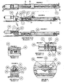
- the drive pulleys 28,29 (having a tooth difference of one) are fixed to rotate with input drive shaft 26.
- These pulleys 28,29 and drive shaft 26 are mounted to a carriage 88 together with driven pulleys 52,53,84 and 85, all of which are free to rotate on respective bearings.
- Drive belt 40 passes from the first drive pulley 28 to the first driven pulley 52, from the first driven pulley 52 to the first guide pulley 48, from the first guide pulley 48 to the third driven pulley 84, from the third driven pulley to the second drive pulley 29, from the second drive pulley to the fourth driven pulley 85, from the fourth driven pulley 85 to the second guide pulley 49, from the second guide pulley 49 to the second driven pulley 53, and from the second driven pulley 53 back to the first drive pulley 28.
- Carriage 88 is supported by bearing blocks 87 which are mounted to track 86 to allow linear motion along the track.
- the drive belt configuration is shown in Figure 13 , with the drive belt 40 defining a first loop between the first guide pulley 48 and the first and third driven pulleys 52,84, and a second loop between the second guide pulley 49 and the second and fourth driven pulleys 53,85.
- Rotation of the drive shaft 26 and pulleys 28,29 in a first direction causes an increase in the length of the first loop and a corresponding decrease in the length of the second loop, causing motion of the carriage 88 along the track 86.
- Reverse rotation of drive shaft 26 reverses the direction of travel.
- This embodiment has an advantage over the first embodiment of linear actuator in that it has a longer travel for a given length of drive belt, and is consequently stiffer.
- This embodiment requires the drive motor (not shown) to be mounted to the carriage 88 which is also an advantage in certain applications.
- the drive pulleys 28 and 29 are each separately rotatable on axles 61 and 62 respectively and have the same number of teeth (although in other designs they could differ by one or more teeth).
- Each of axles 61 and 62 carry gear wheels 63 and 64 respectively, the arrangement being such that the number of teeth on each of gear wheels 63 and 64 is different by one tooth (although in other designs they could have the same number of teeth, or differ by more than one tooth).
- the gears are enmeshed one with the other so that rotation of axle 61 is transmitted to axle 62 in the opposite sense. This also allows the drive belt 40 to pass around the drive pulleys and driven pulleys without any guide pulleys being required to reverse or redirect the path of the drive belt.
- the drive belt 40 passes from the first drive pulley 28 to the first driven pulley 70, from the first driven pulley 70 to the second drive pulley 29, from the second drive pulley 29 to the second driven pulley 72, and from the second driven pulley 72 back to the first drive pulley 29.
- the drive belt 40 defines a first loop between the first driven pulley 70 and the drive pulleys 28,29, and a second loop between the second driven pulley 72 and the drive pulleys 28,29, rotation of the drive pulleys in a first direction causing an increase in the length of the first loop and a corresponding decrease in the length of the second loop.
- the circumference of the respective drive pulleys 28,29 (and consequently the number of teeth if these are toothed pulleys) is the same.
- the difference in the number of gear teeth of gears 63 and 64 there is a corresponding difference in the relative rotational speeds of pulleys 28 and 29 giving a different circumferential speed for the pulleys 28, 29 and therefore a similar result as in the embodiments.
- the displacement of the U-shaped element 73 for one revolution of shaft 61 is equal to (t1/t2*T2/T1)/2, where t1 and t2 are the number of teeth on gears 63 and 64 respectively and T1 and T2 are the number of teeth on pulleys 28 and 29.
- the U-shaped elements 71,73 are interconnected by means of a secondary belt loop 74, which passes about pulley 81.
- the principle of operation for this design is the same as described above, but in this case the driven members are the first and second U-shaped elements 71 and 73 respectively.
- a secondary advantage of this arrangement is that the two driven members can provide separate control means for two differing, but related, functions since each driven member 71,73 moves in the opposite sense on appropriate motion of the drive shaft 61. It should be noted that this design can be used to produce precise rotary motion of the pulley 81 and the secondary belt loop 74.
- a single actuator can be used for two opposing cables by removing the secondary belt loop 74 and associated pulley and using control wires in place of secondary belt loop 74 to provide the necessary tension in the assembly.
- Fig. 21 shows such an arrangement in which the secondary belt loop 74 is replaced by control wires 55a, 55b.
- the arrangement of the drive and driven pulleys of Figures 18-21 can therefore be used in a rotary actuator (to provide controlled rotation of the pulley 81), or in a linear actuator (to provide controlled movement of the driven members 71,73 or elements connected to the control wires 55a,55b.
- FIG. 22-26 The design illustrated in Figures 22-26 is a variant of that described in Figures 18-21 , in which a central drive shaft 80 is adapted to drive first drive pulley 28 and second drive pulley 29 (with in this design a tooth difference of one).
- Drive belt 40 passes from the first drive pulley 28 to the first guide pulley 48, from the first guide pulley 48 to the first driven pulley 70, from the first driven pulley 70 to the second drive pulley 29, from the second drive pulley 29 to the second driven pulley 72, from the second driven pulley 72 to the second guide pulley 49, and from the second guide pulley 49 back to the first drive pulley 28.
- the drive belt 40 defines a first loop between the first driven pulley 70 and the second drive 29 and first guide pulleys 48, and a second loop between the second driven pulley 72 and the second drive pulley 29 and second guide pulleys 49, rotation of the drive pulleys 28,29 in a first direction causing an increase in the length of the first loop and a corresponding decrease in the length of the second loop.
- Driven members or U-shaped elements 71,73 provide attachment to belt 74 by way of tensioning devices 82,83 to provide tension around pulley 81 so that controlled rotation of the pulley 81 can be achieved.
- This design has the advantage of having minimal belt twist and a low profile.
- Figures 18-20 and Figures 22-26 also clarify that an actuator other than that of the present invention is suitable for use in a rotary actuator where torque on the pulley 81. can be in either direction, and the angular position of the pulley can be controlled substantially backlash free.
- the actuators described above further offer the possibility of providing very considerable force on a control wire 55, or carriage 88, or considerable torque on pulley 81, using a motor of relatively small power.
- a worm gear such as 21
- the mechanical advantage of the drive worm 21 and worm wheel 27 is considerable.
- the mechanical advantage of the pulley arrangement is to the effect that the carriage will move by half the pitch of one tooth on a complete revolution of worm wheel 27.
- the mechanical advantage here again is considerable.
- the drive belt 40 flexes around the drive pulleys, driven pulleys and guide pulleys (if present) in the same direction, i.e. towards the teeth of the belt.
- this allows (in the applicable embodiments) a reduction in the size of the pulleys, as compared to embodiments having contraflexure drive.
- actuators of the kind described above result in excellent control for segmented robotic arms of the type described, for example, in international patent application WO2002/016995 and WO2002/100608 .
- These actuators permit the use of relatively low-power motors to exert considerable force on the control wires for such robotic arms and their relative compactness enables a cluster of actuators to be mounted in juxtaposition with the arm with little additional routing of the control wires 55.
Landscapes
- Engineering & Computer Science (AREA)
- General Engineering & Computer Science (AREA)
- Mechanical Engineering (AREA)
- Robotics (AREA)
- Transmission Devices (AREA)
- Manipulator (AREA)
- Fluid-Driven Valves (AREA)
- Actuator (AREA)
- Valve Device For Special Equipments (AREA)
- Control Of Throttle Valves Provided In The Intake System Or In The Exhaust System (AREA)
- Separation Of Suspended Particles By Flocculating Agents (AREA)
- Pharmaceuticals Containing Other Organic And Inorganic Compounds (AREA)
- Cereal-Derived Products (AREA)
- Vehicle Body Suspensions (AREA)
- Massaging Devices (AREA)
- Gear-Shifting Mechanisms (AREA)
- Devices For Conveying Motion By Means Of Endless Flexible Members (AREA)
- Transmissions By Endless Flexible Members (AREA)
- Pulleys (AREA)
Claims (8)
- Actionneur (10) comportant :une première poulie d'entraînement (28) ;une deuxième poulie d'entraînement (29), la première poulie d'entraînementet la deuxième poulie d'entraînement étant interconnectées pour tourner ensemble ;une première poulie commandée (52 ; 70) ;une deuxième poulie commandée (53 ; 72) ;une courroie d'entraînement sans fin (40) en prise avec la première poulie d'entraînement et la deuxième poulie d'entraînement et avec la première poulie commandée et la deuxième poulie commandée ;un moteur (19) connecté pour entraîner la première poulie d'entraînement et la deuxième poulie d'entraînement pour faire tourner et entraîner la courroie d'entraînement sans finun organe commandé (50 ; 88 ; 71, 73) portant au moins l'une des poulies commandées ;la première poulie d'entraînement et la deuxième poulie d'entraînement étant disposées de telle manière que, lors de la rotation de celles-ci, la vitesse périphérique de la première poulie d'entraînement est différente de la vitesse périphérique de la deuxième poulie d'entraînement, la courroie d'entraînement sans fin formant une boucle autour des poulies d'entraînement et des poulies commandées de telle manière que la différence entre la vitesse périphérique de la première poulie d'entraînement et la vitesse périphérique de la deuxième poulie d'entraînement donne lieu au mouvement de l'organe commandé, caractérisé en ce que la première poulie d'entraînement et la deuxième poulie d'entraînement sont montées sur un axe commun (26).
- Actionneur selon la revendication 1, dans lequel la première poulie d'entraînement et la deuxième poulie d'entraînement sont disposées de telle manière que, lors de la rotation de celles-ci, les vitesses périphériques diffèrent en raison du fait que la première poulie d'entraînement a une longueur périphérique différente par rapport à la deuxième poulie d'entraînement.
- Actionneur selon la revendication 1, dans lequel l'organe commandé est un chariot (50 ; 88) monté à des fins de mouvement linéaire.
- Actionneur selon la revendication 3, dans lequel la première poulie commandée et la deuxième poulie commandée sont toutes les deux montées sur le chariot (50 ; 88), l'actionneur comprenant par ailleurs :une première poulie de guidage (48) etune deuxième poulie de guidage (49)la courroie d'entraînement sans fin entrant également en prise avec la première poulie de guidage et la deuxième poulie de guidage.
- Actionneur selon la revendication 4, dans lequel les poulies commandées (52, 53) sont situées entre les poulies d'entraînement (28, 29) et les poulies de guidage (48, 49).
- Actionneur selon la revendication 5, dans lequel la courroie d'entraînement sans fin passe de la première poulie d'entraînement (28) à la première poulie commandée (52), de la première poulie commandée à la deuxième poulie d'entraînement (29), de la deuxième poulie d'entraînement à la première poulie de guidage (48), de la première poulie de guidage à la deuxième poulie commandée (53), de la deuxième poulie commandée à la deuxième poulie de guidage (49), et de la deuxième poulie de guidage de retour à la première poulie d'entraînement, la courroie d'entraînement sans fin définissant une première boucle entre la première poulie commandée et les poulies d'entraînement, et une deuxième boucle entre la deuxième poulie commandée et les poulies de guidage, la rotation des poulies d'entraînement dans une première direction donnant lieu à une augmentation de la longueur de la première boucle et une diminution correspondante de la longueur de la deuxième boucle.
- Actionneur selon la revendication 5, ayant une troisième poulie commandée (84) et une quatrième poulie commandée (85), les poulies d'entraînement (28, 29) et les quatre poulies commandées (52, 53, 84, 85) étant montées sur l'organe commandé (88), dans lequel la courroie d'entraînement sans fin passe de la première poulie d'entraînement (28) à la première poulie commandée (52), de la première poulie commandée à la première poulie de guidage (48), de la première poulie de guidage à la troisième poulie commandée (84), de la troisième poulie commandée à la deuxième poulie d'entraînement (29), de la deuxième poulie d'entraînement à la quatrième poulie commandée (85), de la quatrième poulie commandée à la deuxième poulie de guidage (49), de la deuxième poulie de guidage à la deuxième poulie commandée (53), et de la deuxième poulie commandée de retour à la première poulie d'entraînement, la courroie d'entraînement sans fin définissant une première boucle entre la première poulie de guidage et la première poulie commandée et la troisième poulie commandée, et une deuxième boucle entre la deuxième poulie de guidage et la deuxième poulie commandée et la quatrième poulie commandée, la rotation des poulies d'entraînement dans une première direction donnant lieu à une augmentation de la longueur de la première boucle et une diminution correspondante de la longueur de la deuxième boucle.
- Actionneur selon la revendication 1, dans lequel une conduite de commande (55 ; 55a, 55b) est connectée à l'organe commandé, le mouvement de l'organe commandé donnant lieu à un mouvement correspondant de la conduite de commande.
Applications Claiming Priority (2)
| Application Number | Priority Date | Filing Date | Title |
|---|---|---|---|
| GBGB0416186.5A GB0416186D0 (en) | 2004-07-20 | 2004-07-20 | Improvement in and relating to activators |
| PCT/GB2005/002834 WO2006008515A2 (fr) | 2004-07-20 | 2005-07-18 | Actionneur |
Publications (2)
| Publication Number | Publication Date |
|---|---|
| EP1781450A2 EP1781450A2 (fr) | 2007-05-09 |
| EP1781450B1 true EP1781450B1 (fr) | 2009-05-13 |
Family
ID=32893862
Family Applications (1)
| Application Number | Title | Priority Date | Filing Date |
|---|---|---|---|
| EP05762143A Active EP1781450B1 (fr) | 2004-07-20 | 2005-07-18 | Actionneur |
Country Status (17)
| Country | Link |
|---|---|
| US (2) | US20070219031A1 (fr) |
| EP (1) | EP1781450B1 (fr) |
| JP (1) | JP4797020B2 (fr) |
| KR (1) | KR20070053206A (fr) |
| CN (1) | CN101022928B (fr) |
| AT (1) | ATE431228T1 (fr) |
| AU (1) | AU2005263961A1 (fr) |
| CA (1) | CA2573803A1 (fr) |
| DE (1) | DE602005014489D1 (fr) |
| DK (1) | DK1781450T3 (fr) |
| ES (1) | ES2328598T3 (fr) |
| GB (1) | GB0416186D0 (fr) |
| IL (1) | IL180683A0 (fr) |
| MX (1) | MX2007000755A (fr) |
| RU (1) | RU2381099C2 (fr) |
| WO (1) | WO2006008515A2 (fr) |
| ZA (1) | ZA200700791B (fr) |
Families Citing this family (30)
| Publication number | Priority date | Publication date | Assignee | Title |
|---|---|---|---|---|
| KR100870407B1 (ko) * | 2007-12-27 | 2008-11-25 | 한국원자력연구원 | 케이블 구동 동력 전달장치의 케이블 꼬임 방지장치 |
| DE102009001667A1 (de) | 2008-04-11 | 2009-10-15 | Saia-Burgess Murten Ag | Aktuator |
| AT508241B1 (de) * | 2009-05-05 | 2021-04-15 | Engel Austria Gmbh | Vorrichtung zur umsetzung einer drehbewegung in eine linearbewegung |
| DE102010019681B4 (de) * | 2010-05-07 | 2019-10-02 | Robert Bosch Gmbh | Linearbewegungsvorrichtung mit Omega-Antrieb |
| CN102371590A (zh) | 2010-08-25 | 2012-03-14 | 鸿富锦精密工业(深圳)有限公司 | 机器人的臂结构 |
| CN102166750B (zh) * | 2011-05-16 | 2014-01-29 | 机械科学研究总院先进制造技术研究中心 | 定位梁及具有该定位梁的机器人直线运动单元 |
| DE102011119416A1 (de) * | 2011-11-24 | 2013-05-29 | Agtatec Ag | Antriebsvorrichtung für einen Karusselltürrotor |
| US20130245823A1 (en) * | 2012-03-19 | 2013-09-19 | Kabushiki Kaisha Yaskawa Denki | Robot system, robot hand, and robot system operating method |
| RU2502592C2 (ru) * | 2012-04-04 | 2013-12-27 | Федеральное государственное бюджетное образовательное учреждение высшего профессионального образования "Московский государственный технологический университет "СТАНКИН" (ФГБОУ ВПО МГТУ "СТАНКИН") | Захватное устройство |
| US10018256B1 (en) * | 2012-10-29 | 2018-07-10 | X Development Llc | Low cost block and tackle robot transmission |
| US9326825B2 (en) * | 2013-06-17 | 2016-05-03 | Children's National Medical Center | Patient mounted MRI and CT compatible robot for needle guidance in interventional procedures |
| WO2015013501A1 (fr) * | 2013-07-25 | 2015-01-29 | Liftwave, Inc. Dba Rise Robotics | Organe d'entraînement différentiel |
| RU2549428C2 (ru) * | 2013-09-17 | 2015-04-27 | Федеральное государственное бюджетное образовательное учреждение высшего профессионального образования "Рыбинский государственный авиационный технический университет имени А.А. Соловьева" | Исполнительный механизм |
| JP6153484B2 (ja) * | 2014-02-24 | 2017-06-28 | オリンパス株式会社 | ワイヤ駆動装置およびマニピュレータ |
| US10148735B1 (en) | 2014-03-12 | 2018-12-04 | Instart Logic, Inc. | Application layer load balancer |
| WO2016137918A1 (fr) | 2015-02-23 | 2016-09-01 | Tolomatic, Inc. | Actionneur linéaire de type tige à grande vitesse |
| CN105202159A (zh) * | 2015-09-18 | 2015-12-30 | 东莞市三润田自动化设备有限公司 | 被动轮结构 |
| US10072743B1 (en) | 2016-09-02 | 2018-09-11 | Michael Brian Wittig | Rotary-to-linear transmission system |
| KR101758288B1 (ko) * | 2017-02-08 | 2017-07-14 | 이기상 | 캐리지 서포트 유닛 및 로봇 캐리지 |
| IL271924B2 (en) * | 2017-07-10 | 2023-09-01 | Liftwave Inc Dba Rise Robotics | Normalizing stress distribution and minimizing sidewall friction within angled drive belt systems |
| CN111133229B (zh) | 2017-09-08 | 2023-09-15 | 里弗特威弗股份有限公司以莱斯机器人名义营业 | 高折减传动带驱动的线性致动器 |
| CN108223731A (zh) * | 2018-02-28 | 2018-06-29 | 广西科技大学 | 一种伸缩杆 |
| CN109027157B (zh) * | 2018-07-06 | 2020-04-28 | 燕山大学 | 线性模组 |
| CN109488739A (zh) * | 2019-01-03 | 2019-03-19 | 陈藕生 | 一种差速往复运动装置 |
| US11198215B1 (en) | 2019-08-19 | 2021-12-14 | Joshua Scott | Robotic arm |
| US11746860B2 (en) | 2020-12-23 | 2023-09-05 | Liftwave, Inc. | Self-reeling belt drive |
| KR20230118869A (ko) * | 2020-12-23 | 2023-08-14 | 리프트웨이브, 인크. 디비에이 라이즈 로보틱스 | 셀프-릴링 벨트 구동 기구 |
| CN116745230B (zh) * | 2020-12-23 | 2024-07-12 | 里弗特威弗股份有限公司以莱斯机器人名义营业 | 自卷条带驱动机构 |
| CN112720561B (zh) * | 2020-12-30 | 2024-03-12 | 沈阳新松机器人自动化股份有限公司 | 一种方形模块化力位双闭环控制的超冗余绳驱动机器人 |
| KR102640865B1 (ko) | 2021-11-15 | 2024-02-27 | 주식회사 드림로봇 | 증배속 이송이 가능한 벨트형 액츄에이터 |
Family Cites Families (56)
| Publication number | Priority date | Publication date | Assignee | Title |
|---|---|---|---|---|
| US331487A (en) * | 1885-12-01 | Churning device | ||
| US396430A (en) * | 1889-01-22 | Helm reichel | ||
| US324509A (en) * | 1885-08-18 | winans | ||
| US2685377A (en) * | 1947-06-03 | 1954-08-03 | Auger Harold | Power transmission mechanism |
| US2705427A (en) * | 1954-07-29 | 1955-04-05 | Pieter W Schipper | Feed and rapid control for machine tools |
| US2859629A (en) * | 1955-04-28 | 1958-11-11 | Leland L Parker | Differential cable drive mechanism |
| US2884788A (en) * | 1957-09-17 | 1959-05-05 | Leeds & Northrup Co | Cable transmission systems for recorders |
| US3044312A (en) * | 1960-05-20 | 1962-07-17 | Curtiss Wright Corp | Mechanism for converting rotary to linear movement |
| NL129819C (fr) * | 1963-12-06 | |||
| US3231260A (en) * | 1964-01-02 | 1966-01-25 | Howard L Shirley | Motion translating device |
| US3810689A (en) * | 1971-08-23 | 1974-05-14 | Polaroid Corp | Device for varying light transmission employing roller-cable mechanism |
| BE795860A (fr) * | 1972-02-25 | 1973-08-23 | Xerox Corp | Machines a imprimer a grande vitesse avec cable de chariot a compensation de deplacement |
| US3828615A (en) * | 1973-02-15 | 1974-08-13 | Connor C O | Roller band actuator |
| US3850043A (en) * | 1974-01-11 | 1974-11-26 | J Tarbox | Roller band apparatus |
| GB1479281A (en) | 1974-06-12 | 1977-07-13 | Floyd G | Linear actuator mechanisms |
| US3910130A (en) * | 1974-10-29 | 1975-10-07 | Jr Charles W Traughber | Self-tensioning cable drive |
| US4053043A (en) * | 1975-12-29 | 1977-10-11 | Xerox Corporation | Means and method for enhancing ribbon lift |
| JPS52121404A (en) * | 1976-04-05 | 1977-10-12 | Ricoh Kk | Carriage feeding mechanism for printer |
| FR2429061A1 (fr) * | 1978-06-23 | 1980-01-18 | Pont A Mousson | Machine d'extraction de tuyaux centrifuges |
| IL57913A (en) * | 1979-07-27 | 1983-09-30 | Beta Eng & Dev Ltd | Multi-axes positioning system |
| US4403877A (en) * | 1980-04-08 | 1983-09-13 | Xerox Corporation | Snubbed anchoring apparatus |
| FR2501563B1 (fr) * | 1981-03-10 | 1986-07-18 | Sormel Sa | Manipulateur automatique |
| US4507044A (en) * | 1981-12-08 | 1985-03-26 | Zymark Corporation | Robot and control system |
| US4470363A (en) * | 1982-08-23 | 1984-09-11 | Teleflex Incorporated | Cable operated steering system |
| US4485594A (en) * | 1982-09-07 | 1984-12-04 | Brown & Sharpe Manufacturing Company | Surface grinding machine |
| US4524520A (en) * | 1983-02-24 | 1985-06-25 | Levy Nessim I | Carriage positioning system |
| EP0161431A1 (fr) * | 1984-05-15 | 1985-11-21 | Siemens Aktiengesellschaft | Transmission réversible |
| JPS61140665A (ja) * | 1984-12-10 | 1986-06-27 | Matsushita Electric Ind Co Ltd | 直進移動装置 |
| US4872799A (en) * | 1985-05-16 | 1989-10-10 | Btu Engineering Corporation | Boat transfer and queuing furnace elevator and method |
| CH668991A5 (de) * | 1985-11-18 | 1989-02-15 | Luwa Ag | Arbeitseinrichtung, insbesondere an einer textilmaschine. |
| CH675986A5 (fr) * | 1988-05-26 | 1990-11-30 | Wild Leitz Ag | |
| JPH02199345A (ja) * | 1989-01-30 | 1990-08-07 | Canon Inc | 直進移動装置 |
| US5063676A (en) * | 1990-02-13 | 1991-11-12 | Gerber Garment Technology, Inc. | Cable drive system for carriage movement and method of use |
| US5073079A (en) * | 1990-05-17 | 1991-12-17 | Intelmatec Corporation | Modular loading-unloading system for integrated circuits or the like |
| US5276970A (en) * | 1991-10-30 | 1994-01-11 | Hewlett-Packard Company | Codestrip in a large-format image-related device |
| DE4136119C2 (de) * | 1991-11-02 | 1994-03-17 | Erno Raumfahrttechnik Gmbh | Linearantrieb |
| JPH06174038A (ja) * | 1992-12-02 | 1994-06-21 | Matsushita Electric Ind Co Ltd | 直線移動装置 |
| JP2989404B2 (ja) * | 1993-01-26 | 1999-12-13 | シャープ株式会社 | 差動プリー変速機構 |
| JPH07227475A (ja) * | 1994-02-21 | 1995-08-29 | Ryowa Kk | クレーン式ゲーム機のクレーン機構 |
| JPH07328882A (ja) * | 1994-06-08 | 1995-12-19 | Mitsuba Electric Mfg Co Ltd | X−y移動機構 |
| US5568189A (en) * | 1994-06-21 | 1996-10-22 | Kneller; Paul J. | Aerial support platform mechanism with five axes of motion |
| US5611248A (en) * | 1995-06-02 | 1997-03-18 | Ats Automation Tooling Systems Inc. | Two-axis robot |
| US5830094A (en) * | 1995-11-03 | 1998-11-03 | Brown & Sharpe Manufacturing Company | Transmission for converting rotary motion into linear motion |
| US6503163B1 (en) * | 1996-05-15 | 2003-01-07 | Sensar, Inc. | Precision cable drive |
| US6134978A (en) * | 1997-11-13 | 2000-10-24 | Lin; Bob | Transmission mechanism for a scanner |
| JPH11226890A (ja) * | 1998-02-13 | 1999-08-24 | Mac Sangyo Kiki Kk | 産業用ロボットの発塵抑止装置 |
| US6216797B1 (en) * | 1999-01-11 | 2001-04-17 | Case Corporation | Thrust system for a horizontal directional drill |
| US6501198B2 (en) | 2000-02-17 | 2002-12-31 | Jlg Industries, Inc. | Control lever for heavy machinery with near-proximity sensing |
| JP2001241525A (ja) * | 2000-02-25 | 2001-09-07 | Fuminori Hirose | 直線移動装置 |
| TW525880U (en) * | 2000-07-07 | 2003-03-21 | Veutron Corp | Transmission mechanism of scanner |
| JP2002199345A (ja) | 2000-12-26 | 2002-07-12 | Ricoh Co Ltd | 動画像検索装置 |
| JP3937067B2 (ja) * | 2002-03-18 | 2007-06-27 | Smc株式会社 | 電動アクチュエータおよびその組み付け方法 |
| US6626630B1 (en) * | 2002-06-24 | 2003-09-30 | Bakery Holdings Llc | Cartesian robot |
| US7331967B2 (en) * | 2002-09-09 | 2008-02-19 | Hansen Medical, Inc. | Surgical instrument coupling mechanism |
| GB2435315B (en) * | 2006-02-15 | 2010-10-06 | Thales Holdings Uk Plc | Rotary to linear transmission |
| DE602007006513D1 (de) * | 2007-11-12 | 2010-06-24 | Pilz Gmbh & Co Kg | Mehrachsiger Roboter für Hochgeschwindigkeitsanwendungen |
-
2004
- 2004-07-20 GB GBGB0416186.5A patent/GB0416186D0/en not_active Ceased
-
2005
- 2005-07-18 DE DE602005014489T patent/DE602005014489D1/de active Active
- 2005-07-18 DK DK05762143T patent/DK1781450T3/da active
- 2005-07-18 EP EP05762143A patent/EP1781450B1/fr active Active
- 2005-07-18 AT AT05762143T patent/ATE431228T1/de active
- 2005-07-18 CN CN2005800315570A patent/CN101022928B/zh not_active Expired - Fee Related
- 2005-07-18 ZA ZA200700791A patent/ZA200700791B/xx unknown
- 2005-07-18 AU AU2005263961A patent/AU2005263961A1/en not_active Abandoned
- 2005-07-18 MX MX2007000755A patent/MX2007000755A/es active IP Right Grant
- 2005-07-18 RU RU2007100059/02A patent/RU2381099C2/ru not_active IP Right Cessation
- 2005-07-18 JP JP2007522015A patent/JP4797020B2/ja not_active Expired - Fee Related
- 2005-07-18 ES ES05762143T patent/ES2328598T3/es active Active
- 2005-07-18 KR KR1020077001468A patent/KR20070053206A/ko not_active Application Discontinuation
- 2005-07-18 CA CA002573803A patent/CA2573803A1/fr not_active Abandoned
- 2005-07-18 WO PCT/GB2005/002834 patent/WO2006008515A2/fr active Application Filing
- 2005-07-18 US US11/572,371 patent/US20070219031A1/en not_active Abandoned
-
2007
- 2007-01-14 IL IL180683A patent/IL180683A0/en unknown
-
2010
- 2010-04-14 US US12/760,228 patent/US8516913B2/en not_active Expired - Fee Related
Also Published As
| Publication number | Publication date |
|---|---|
| ATE431228T1 (de) | 2009-05-15 |
| CN101022928A (zh) | 2007-08-22 |
| MX2007000755A (es) | 2007-05-23 |
| WO2006008515A3 (fr) | 2006-04-20 |
| US8516913B2 (en) | 2013-08-27 |
| US20100210383A1 (en) | 2010-08-19 |
| EP1781450A2 (fr) | 2007-05-09 |
| JP4797020B2 (ja) | 2011-10-19 |
| ZA200700791B (en) | 2008-12-31 |
| DK1781450T3 (da) | 2009-08-24 |
| CA2573803A1 (fr) | 2006-01-26 |
| CN101022928B (zh) | 2012-06-06 |
| AU2005263961A1 (en) | 2006-01-26 |
| RU2007100059A (ru) | 2008-08-27 |
| GB0416186D0 (en) | 2004-08-18 |
| KR20070053206A (ko) | 2007-05-23 |
| IL180683A0 (en) | 2007-06-03 |
| DE602005014489D1 (de) | 2009-06-25 |
| WO2006008515A2 (fr) | 2006-01-26 |
| JP2008506546A (ja) | 2008-03-06 |
| RU2381099C2 (ru) | 2010-02-10 |
| ES2328598T3 (es) | 2009-11-16 |
| US20070219031A1 (en) | 2007-09-20 |
Similar Documents
| Publication | Publication Date | Title |
|---|---|---|
| EP1781450B1 (fr) | Actionneur | |
| US5690567A (en) | Transmission for converting rotary motion into linear motion | |
| JP2000161457A (ja) | 直進/回転機構 | |
| US6375589B1 (en) | Roller chain sprocket | |
| US20150082765A1 (en) | Cable stranding apparatus employing a hollow-shaft guide member driver | |
| US5033995A (en) | Motion transforming device, and in particular a speed reduction gear | |
| WO1990000509A1 (fr) | Dispositif de positionnement rapide de chariots lourds | |
| US10823263B1 (en) | Rotary-to-linear transmission system | |
| CA1149793A (fr) | Tendeur de conducteurs sur toronneuse | |
| JPH06174038A (ja) | 直線移動装置 | |
| US6634164B2 (en) | Apparatus for producing a stranded cable with alternating twist direction made of strand elements | |
| AU2010226893B2 (en) | Cable stranding methods employing a hollow-shaft guide member driver | |
| US5331862A (en) | Linear drive for converting a rotational drive movement into a linear output movement | |
| JP2519749B2 (ja) | ロボットの動力伝達装置 | |
| JPS60263761A (ja) | ロ−プ駆動装置 | |
| JP4017683B2 (ja) | ラック駆動装置 | |
| US4923434A (en) | High precision drive mechanism | |
| JP2748293B2 (ja) | 高剛性線条体の送り出し方法および送出装置 | |
| JPH0911161A (ja) | 単軸ロボット | |
| JPS61214984A (ja) | 産業用ロボツト | |
| JPH08152050A (ja) | タイミングベルト減速機構 | |
| JPS5959390A (ja) | 工業用ロボツトの手首部 | |
| WO2003078240A1 (fr) | Variateur de vitesse de transmission pour cycles | |
| KR19980029470U (ko) | 평행축의 동력전달장치 | |
| KR100456792B1 (ko) | 백래쉬가 억제된 벨트 장치 |
Legal Events
| Date | Code | Title | Description |
|---|---|---|---|
| PUAI | Public reference made under article 153(3) epc to a published international application that has entered the european phase |
Free format text: ORIGINAL CODE: 0009012 |
|
| 17P | Request for examination filed |
Effective date: 20070124 |
|
| AK | Designated contracting states |
Kind code of ref document: A2 Designated state(s): AT BE BG CH CY CZ DE DK EE ES FI FR GB GR HU IE IS IT LI LT LU LV MC NL PL PT RO SE SI SK TR |
|
| AX | Request for extension of the european patent |
Extension state: BA HR YU |
|
| RAX | Requested extension states of the european patent have changed |
Extension state: YU Payment date: 20070124 Extension state: HR Payment date: 20070124 Extension state: BA Payment date: 20070124 |
|
| 17Q | First examination report despatched |
Effective date: 20080212 |
|
| GRAP | Despatch of communication of intention to grant a patent |
Free format text: ORIGINAL CODE: EPIDOSNIGR1 |
|
| GRAP | Despatch of communication of intention to grant a patent |
Free format text: ORIGINAL CODE: EPIDOSNIGR1 |
|
| GRAS | Grant fee paid |
Free format text: ORIGINAL CODE: EPIDOSNIGR3 |
|
| GRAF | Information related to payment of grant fee modified |
Free format text: ORIGINAL CODE: EPIDOSCIGR3 |
|
| GRAA | (expected) grant |
Free format text: ORIGINAL CODE: 0009210 |
|
| GRAL | Information related to payment of fee for publishing/printing deleted |
Free format text: ORIGINAL CODE: EPIDOSDIGR3 |
|
| GRAS | Grant fee paid |
Free format text: ORIGINAL CODE: EPIDOSNIGR3 |
|
| AK | Designated contracting states |
Kind code of ref document: B1 Designated state(s): AT BE BG CH CY CZ DE DK EE ES FI FR GB GR HU IE IS IT LI LT LU LV MC NL PL PT RO SE SI SK TR |
|
| AX | Request for extension of the european patent |
Extension state: BA HR YU |
|
| REG | Reference to a national code |
Ref country code: GB Ref legal event code: FG4D |
|
| REG | Reference to a national code |
Ref country code: CH Ref legal event code: EP |
|
| REG | Reference to a national code |
Ref country code: IE Ref legal event code: FG4D |
|
| REF | Corresponds to: |
Ref document number: 602005014489 Country of ref document: DE Date of ref document: 20090625 Kind code of ref document: P |
|
| REG | Reference to a national code |
Ref country code: DK Ref legal event code: T3 |
|
| REG | Reference to a national code |
Ref country code: SE Ref legal event code: TRGR |
|
| REG | Reference to a national code |
Ref country code: CH Ref legal event code: NV Representative=s name: KELLER & PARTNER PATENTANWAELTE AG WINTERTHUR |
|
| PG25 | Lapsed in a contracting state [announced via postgrant information from national office to epo] |
Ref country code: LT Free format text: LAPSE BECAUSE OF FAILURE TO SUBMIT A TRANSLATION OF THE DESCRIPTION OR TO PAY THE FEE WITHIN THE PRESCRIBED TIME-LIMIT Effective date: 20090513 Ref country code: FI Free format text: LAPSE BECAUSE OF FAILURE TO SUBMIT A TRANSLATION OF THE DESCRIPTION OR TO PAY THE FEE WITHIN THE PRESCRIBED TIME-LIMIT Effective date: 20090513 Ref country code: PT Free format text: LAPSE BECAUSE OF FAILURE TO SUBMIT A TRANSLATION OF THE DESCRIPTION OR TO PAY THE FEE WITHIN THE PRESCRIBED TIME-LIMIT Effective date: 20090913 |
|
| REG | Reference to a national code |
Ref country code: ES Ref legal event code: FG2A Ref document number: 2328598 Country of ref document: ES Kind code of ref document: T3 |
|
| PG25 | Lapsed in a contracting state [announced via postgrant information from national office to epo] |
Ref country code: SI Free format text: LAPSE BECAUSE OF FAILURE TO SUBMIT A TRANSLATION OF THE DESCRIPTION OR TO PAY THE FEE WITHIN THE PRESCRIBED TIME-LIMIT Effective date: 20090513 Ref country code: PL Free format text: LAPSE BECAUSE OF FAILURE TO SUBMIT A TRANSLATION OF THE DESCRIPTION OR TO PAY THE FEE WITHIN THE PRESCRIBED TIME-LIMIT Effective date: 20090513 Ref country code: LV Free format text: LAPSE BECAUSE OF FAILURE TO SUBMIT A TRANSLATION OF THE DESCRIPTION OR TO PAY THE FEE WITHIN THE PRESCRIBED TIME-LIMIT Effective date: 20090513 Ref country code: IS Free format text: LAPSE BECAUSE OF FAILURE TO SUBMIT A TRANSLATION OF THE DESCRIPTION OR TO PAY THE FEE WITHIN THE PRESCRIBED TIME-LIMIT Effective date: 20090913 |
|
| PG25 | Lapsed in a contracting state [announced via postgrant information from national office to epo] |
Ref country code: EE Free format text: LAPSE BECAUSE OF FAILURE TO SUBMIT A TRANSLATION OF THE DESCRIPTION OR TO PAY THE FEE WITHIN THE PRESCRIBED TIME-LIMIT Effective date: 20090513 |
|
| PG25 | Lapsed in a contracting state [announced via postgrant information from national office to epo] |
Ref country code: MC Free format text: LAPSE BECAUSE OF NON-PAYMENT OF DUE FEES Effective date: 20090731 Ref country code: SK Free format text: LAPSE BECAUSE OF FAILURE TO SUBMIT A TRANSLATION OF THE DESCRIPTION OR TO PAY THE FEE WITHIN THE PRESCRIBED TIME-LIMIT Effective date: 20090513 |
|
| PLBE | No opposition filed within time limit |
Free format text: ORIGINAL CODE: 0009261 |
|
| STAA | Information on the status of an ep patent application or granted ep patent |
Free format text: STATUS: NO OPPOSITION FILED WITHIN TIME LIMIT |
|
| PG25 | Lapsed in a contracting state [announced via postgrant information from national office to epo] |
Ref country code: BG Free format text: LAPSE BECAUSE OF FAILURE TO SUBMIT A TRANSLATION OF THE DESCRIPTION OR TO PAY THE FEE WITHIN THE PRESCRIBED TIME-LIMIT Effective date: 20090813 |
|
| 26N | No opposition filed |
Effective date: 20100216 |
|
| PG25 | Lapsed in a contracting state [announced via postgrant information from national office to epo] |
Ref country code: GR Free format text: LAPSE BECAUSE OF FAILURE TO SUBMIT A TRANSLATION OF THE DESCRIPTION OR TO PAY THE FEE WITHIN THE PRESCRIBED TIME-LIMIT Effective date: 20090814 |
|
| PG25 | Lapsed in a contracting state [announced via postgrant information from national office to epo] |
Ref country code: RO Free format text: LAPSE BECAUSE OF FAILURE TO SUBMIT A TRANSLATION OF THE DESCRIPTION OR TO PAY THE FEE WITHIN THE PRESCRIBED TIME-LIMIT Effective date: 20090513 |
|
| PG25 | Lapsed in a contracting state [announced via postgrant information from national office to epo] |
Ref country code: LU Free format text: LAPSE BECAUSE OF NON-PAYMENT OF DUE FEES Effective date: 20090718 |
|
| PG25 | Lapsed in a contracting state [announced via postgrant information from national office to epo] |
Ref country code: IT Free format text: LAPSE BECAUSE OF NON-PAYMENT OF DUE FEES Effective date: 20100718 |
|
| PG25 | Lapsed in a contracting state [announced via postgrant information from national office to epo] |
Ref country code: HU Free format text: LAPSE BECAUSE OF FAILURE TO SUBMIT A TRANSLATION OF THE DESCRIPTION OR TO PAY THE FEE WITHIN THE PRESCRIBED TIME-LIMIT Effective date: 20091114 |
|
| PGRI | Patent reinstated in contracting state [announced from national office to epo] |
Ref country code: IT Effective date: 20110616 |
|
| PG25 | Lapsed in a contracting state [announced via postgrant information from national office to epo] |
Ref country code: TR Free format text: LAPSE BECAUSE OF FAILURE TO SUBMIT A TRANSLATION OF THE DESCRIPTION OR TO PAY THE FEE WITHIN THE PRESCRIBED TIME-LIMIT Effective date: 20090513 |
|
| PG25 | Lapsed in a contracting state [announced via postgrant information from national office to epo] |
Ref country code: CY Free format text: LAPSE BECAUSE OF FAILURE TO SUBMIT A TRANSLATION OF THE DESCRIPTION OR TO PAY THE FEE WITHIN THE PRESCRIBED TIME-LIMIT Effective date: 20090513 |
|
| PGFP | Annual fee paid to national office [announced via postgrant information from national office to epo] |
Ref country code: CZ Payment date: 20110722 Year of fee payment: 7 |
|
| PGFP | Annual fee paid to national office [announced via postgrant information from national office to epo] |
Ref country code: SE Payment date: 20120731 Year of fee payment: 8 |
|
| PGFP | Annual fee paid to national office [announced via postgrant information from national office to epo] |
Ref country code: FR Payment date: 20120817 Year of fee payment: 8 Ref country code: ES Payment date: 20120830 Year of fee payment: 8 |
|
| PGFP | Annual fee paid to national office [announced via postgrant information from national office to epo] |
Ref country code: NL Payment date: 20120730 Year of fee payment: 8 Ref country code: BE Payment date: 20120903 Year of fee payment: 8 |
|
| PGFP | Annual fee paid to national office [announced via postgrant information from national office to epo] |
Ref country code: IE Payment date: 20130128 Year of fee payment: 8 Ref country code: CH Payment date: 20130130 Year of fee payment: 8 Ref country code: DK Payment date: 20130129 Year of fee payment: 8 |
|
| PGFP | Annual fee paid to national office [announced via postgrant information from national office to epo] |
Ref country code: AT Payment date: 20130128 Year of fee payment: 8 |
|
| BERE | Be: lapsed |
Owner name: JONES, TIMOTHY JOHN Effective date: 20130731 |
|
| REG | Reference to a national code |
Ref country code: NL Ref legal event code: V1 Effective date: 20140201 |
|
| REG | Reference to a national code |
Ref country code: DK Ref legal event code: EBP Effective date: 20130731 |
|
| REG | Reference to a national code |
Ref country code: CH Ref legal event code: PL |
|
| REG | Reference to a national code |
Ref country code: SE Ref legal event code: EUG |
|
| REG | Reference to a national code |
Ref country code: AT Ref legal event code: MM01 Ref document number: 431228 Country of ref document: AT Kind code of ref document: T Effective date: 20130718 |
|
| REG | Reference to a national code |
Ref country code: IE Ref legal event code: MM4A |
|
| REG | Reference to a national code |
Ref country code: FR Ref legal event code: ST Effective date: 20140331 |
|
| PG25 | Lapsed in a contracting state [announced via postgrant information from national office to epo] |
Ref country code: SE Free format text: LAPSE BECAUSE OF NON-PAYMENT OF DUE FEES Effective date: 20130719 Ref country code: CH Free format text: LAPSE BECAUSE OF NON-PAYMENT OF DUE FEES Effective date: 20130731 Ref country code: BE Free format text: LAPSE BECAUSE OF NON-PAYMENT OF DUE FEES Effective date: 20130731 Ref country code: LI Free format text: LAPSE BECAUSE OF NON-PAYMENT OF DUE FEES Effective date: 20130731 Ref country code: NL Free format text: LAPSE BECAUSE OF NON-PAYMENT OF DUE FEES Effective date: 20140201 Ref country code: CZ Free format text: LAPSE BECAUSE OF NON-PAYMENT OF DUE FEES Effective date: 20130718 |
|
| PG25 | Lapsed in a contracting state [announced via postgrant information from national office to epo] |
Ref country code: AT Free format text: LAPSE BECAUSE OF NON-PAYMENT OF DUE FEES Effective date: 20130718 Ref country code: FR Free format text: LAPSE BECAUSE OF NON-PAYMENT OF DUE FEES Effective date: 20130731 |
|
| REG | Reference to a national code |
Ref country code: GB Ref legal event code: 732E Free format text: REGISTERED BETWEEN 20140605 AND 20140611 |
|
| REG | Reference to a national code |
Ref country code: DE Ref legal event code: R082 Ref document number: 602005014489 Country of ref document: DE Representative=s name: BARDEHLE PAGENBERG PARTNERSCHAFT MBB PATENTANW, DE |
|
| PG25 | Lapsed in a contracting state [announced via postgrant information from national office to epo] |
Ref country code: IE Free format text: LAPSE BECAUSE OF NON-PAYMENT OF DUE FEES Effective date: 20130718 |
|
| REG | Reference to a national code |
Ref country code: DE Ref legal event code: R082 Ref document number: 602005014489 Country of ref document: DE Representative=s name: BARDEHLE PAGENBERG PARTNERSCHAFT MBB PATENTANW, DE Effective date: 20140708 Ref country code: DE Ref legal event code: R081 Ref document number: 602005014489 Country of ref document: DE Owner name: HARMONIC LINEAR DRIVES LTD., BRANSLEY, GB Free format text: FORMER OWNER: JONES, TIMOTHY JOHN, CHIPPING NORTON, GB Effective date: 20140708 Ref country code: DE Ref legal event code: R081 Ref document number: 602005014489 Country of ref document: DE Owner name: MOOG INC., ELMA, US Free format text: FORMER OWNER: JONES, TIMOTHY JOHN, CHIPPING NORTON, GB Effective date: 20140708 |
|
| REG | Reference to a national code |
Ref country code: ES Ref legal event code: FD2A Effective date: 20140905 |
|
| PG25 | Lapsed in a contracting state [announced via postgrant information from national office to epo] |
Ref country code: DK Free format text: LAPSE BECAUSE OF NON-PAYMENT OF DUE FEES Effective date: 20130731 |
|
| PG25 | Lapsed in a contracting state [announced via postgrant information from national office to epo] |
Ref country code: ES Free format text: LAPSE BECAUSE OF NON-PAYMENT OF DUE FEES Effective date: 20130719 |
|
| REG | Reference to a national code |
Ref country code: DE Ref legal event code: R082 Ref document number: 602005014489 Country of ref document: DE Representative=s name: BARDEHLE PAGENBERG PARTNERSCHAFT MBB PATENTANW, DE Ref country code: DE Ref legal event code: R081 Ref document number: 602005014489 Country of ref document: DE Owner name: MOOG INC., ELMA, US Free format text: FORMER OWNER: HARMONIC LINEAR DRIVES LTD., BRANSLEY, SOUTH YORKSHIRE, GB |
|
| REG | Reference to a national code |
Ref country code: GB Ref legal event code: 732E Free format text: REGISTERED BETWEEN 20180419 AND 20180425 |
|
| PGFP | Annual fee paid to national office [announced via postgrant information from national office to epo] |
Ref country code: DE Payment date: 20190719 Year of fee payment: 15 Ref country code: IT Payment date: 20190729 Year of fee payment: 15 |
|
| PGFP | Annual fee paid to national office [announced via postgrant information from national office to epo] |
Ref country code: GB Payment date: 20200914 Year of fee payment: 16 |
|
| REG | Reference to a national code |
Ref country code: DE Ref legal event code: R119 Ref document number: 602005014489 Country of ref document: DE |
|
| PG25 | Lapsed in a contracting state [announced via postgrant information from national office to epo] |
Ref country code: DE Free format text: LAPSE BECAUSE OF NON-PAYMENT OF DUE FEES Effective date: 20210202 |
|
| GBPC | Gb: european patent ceased through non-payment of renewal fee |
Effective date: 20210718 |
|
| PG25 | Lapsed in a contracting state [announced via postgrant information from national office to epo] |
Ref country code: GB Free format text: LAPSE BECAUSE OF NON-PAYMENT OF DUE FEES Effective date: 20210718 |
|
| PG25 | Lapsed in a contracting state [announced via postgrant information from national office to epo] |
Ref country code: IT Free format text: LAPSE BECAUSE OF NON-PAYMENT OF DUE FEES Effective date: 20200718 |