EP1775603B1 - Light diffusion sheet and backlight unit using the same - Google Patents
Light diffusion sheet and backlight unit using the same Download PDFInfo
- Publication number
- EP1775603B1 EP1775603B1 EP06021166A EP06021166A EP1775603B1 EP 1775603 B1 EP1775603 B1 EP 1775603B1 EP 06021166 A EP06021166 A EP 06021166A EP 06021166 A EP06021166 A EP 06021166A EP 1775603 B1 EP1775603 B1 EP 1775603B1
- Authority
- EP
- European Patent Office
- Prior art keywords
- light diffusion
- beads
- diffusion sheet
- less
- light
- Prior art date
- Legal status (The legal status is an assumption and is not a legal conclusion. Google has not performed a legal analysis and makes no representation as to the accuracy of the status listed.)
- Active
Links
Images

Classifications
-
- G—PHYSICS
- G02—OPTICS
- G02B—OPTICAL ELEMENTS, SYSTEMS OR APPARATUS
- G02B6/00—Light guides; Structural details of arrangements comprising light guides and other optical elements, e.g. couplings
- G02B6/0001—Light guides; Structural details of arrangements comprising light guides and other optical elements, e.g. couplings specially adapted for lighting devices or systems
- G02B6/0011—Light guides; Structural details of arrangements comprising light guides and other optical elements, e.g. couplings specially adapted for lighting devices or systems the light guides being planar or of plate-like form
- G02B6/0013—Means for improving the coupling-in of light from the light source into the light guide
- G02B6/0023—Means for improving the coupling-in of light from the light source into the light guide provided by one optical element, or plurality thereof, placed between the light guide and the light source, or around the light source
- G02B6/0025—Diffusing sheet or layer; Prismatic sheet or layer
-
- G—PHYSICS
- G02—OPTICS
- G02B—OPTICAL ELEMENTS, SYSTEMS OR APPARATUS
- G02B5/00—Optical elements other than lenses
- G02B5/02—Diffusing elements; Afocal elements
- G02B5/0205—Diffusing elements; Afocal elements characterised by the diffusing properties
- G02B5/021—Diffusing elements; Afocal elements characterised by the diffusing properties the diffusion taking place at the element's surface, e.g. by means of surface roughening or microprismatic structures
- G02B5/0226—Diffusing elements; Afocal elements characterised by the diffusing properties the diffusion taking place at the element's surface, e.g. by means of surface roughening or microprismatic structures having particles on the surface
-
- G—PHYSICS
- G02—OPTICS
- G02B—OPTICAL ELEMENTS, SYSTEMS OR APPARATUS
- G02B5/00—Optical elements other than lenses
- G02B5/02—Diffusing elements; Afocal elements
- G02B5/0273—Diffusing elements; Afocal elements characterized by the use
- G02B5/0278—Diffusing elements; Afocal elements characterized by the use used in transmission
-
- G—PHYSICS
- G02—OPTICS
- G02F—OPTICAL DEVICES OR ARRANGEMENTS FOR THE CONTROL OF LIGHT BY MODIFICATION OF THE OPTICAL PROPERTIES OF THE MEDIA OF THE ELEMENTS INVOLVED THEREIN; NON-LINEAR OPTICS; FREQUENCY-CHANGING OF LIGHT; OPTICAL LOGIC ELEMENTS; OPTICAL ANALOGUE/DIGITAL CONVERTERS
- G02F1/00—Devices or arrangements for the control of the intensity, colour, phase, polarisation or direction of light arriving from an independent light source, e.g. switching, gating or modulating; Non-linear optics
- G02F1/01—Devices or arrangements for the control of the intensity, colour, phase, polarisation or direction of light arriving from an independent light source, e.g. switching, gating or modulating; Non-linear optics for the control of the intensity, phase, polarisation or colour
- G02F1/13—Devices or arrangements for the control of the intensity, colour, phase, polarisation or direction of light arriving from an independent light source, e.g. switching, gating or modulating; Non-linear optics for the control of the intensity, phase, polarisation or colour based on liquid crystals, e.g. single liquid crystal display cells
- G02F1/133—Constructional arrangements; Operation of liquid crystal cells; Circuit arrangements
- G02F1/1333—Constructional arrangements; Manufacturing methods
- G02F1/1335—Structural association of cells with optical devices, e.g. polarisers or reflectors
-
- Y—GENERAL TAGGING OF NEW TECHNOLOGICAL DEVELOPMENTS; GENERAL TAGGING OF CROSS-SECTIONAL TECHNOLOGIES SPANNING OVER SEVERAL SECTIONS OF THE IPC; TECHNICAL SUBJECTS COVERED BY FORMER USPC CROSS-REFERENCE ART COLLECTIONS [XRACs] AND DIGESTS
- Y10—TECHNICAL SUBJECTS COVERED BY FORMER USPC
- Y10T—TECHNICAL SUBJECTS COVERED BY FORMER US CLASSIFICATION
- Y10T428/00—Stock material or miscellaneous articles
- Y10T428/24—Structurally defined web or sheet [e.g., overall dimension, etc.]
- Y10T428/24273—Structurally defined web or sheet [e.g., overall dimension, etc.] including aperture
- Y10T428/24298—Noncircular aperture [e.g., slit, diamond, rectangular, etc.]
-
- Y—GENERAL TAGGING OF NEW TECHNOLOGICAL DEVELOPMENTS; GENERAL TAGGING OF CROSS-SECTIONAL TECHNOLOGIES SPANNING OVER SEVERAL SECTIONS OF THE IPC; TECHNICAL SUBJECTS COVERED BY FORMER USPC CROSS-REFERENCE ART COLLECTIONS [XRACs] AND DIGESTS
- Y10—TECHNICAL SUBJECTS COVERED BY FORMER USPC
- Y10T—TECHNICAL SUBJECTS COVERED BY FORMER US CLASSIFICATION
- Y10T428/00—Stock material or miscellaneous articles
- Y10T428/24—Structurally defined web or sheet [e.g., overall dimension, etc.]
- Y10T428/24355—Continuous and nonuniform or irregular surface on layer or component [e.g., roofing, etc.]
- Y10T428/24372—Particulate matter
-
- Y—GENERAL TAGGING OF NEW TECHNOLOGICAL DEVELOPMENTS; GENERAL TAGGING OF CROSS-SECTIONAL TECHNOLOGIES SPANNING OVER SEVERAL SECTIONS OF THE IPC; TECHNICAL SUBJECTS COVERED BY FORMER USPC CROSS-REFERENCE ART COLLECTIONS [XRACs] AND DIGESTS
- Y10—TECHNICAL SUBJECTS COVERED BY FORMER USPC
- Y10T—TECHNICAL SUBJECTS COVERED BY FORMER US CLASSIFICATION
- Y10T428/00—Stock material or miscellaneous articles
- Y10T428/24—Structurally defined web or sheet [e.g., overall dimension, etc.]
- Y10T428/24942—Structurally defined web or sheet [e.g., overall dimension, etc.] including components having same physical characteristic in differing degree
Definitions
- the present invention relates to light diffusion sheets according to the preamble of claim 1, which have directional light diffusion function to allow transmitted rays of light to diffuse while collecting to a side in a normal direction and which are particularly suitable for a backlight of a liquid crystal display device, and backlight units in which the light diffusion sheet is used.
- a light diffusion sheet according to the preamble of claim 1 is disclosed in each of the following documents: US 6 852 396 B1 , US 5 706 134 A , JP 07 218 705 A , JP 2004 026 974 A , WO 2005/052 677 A1 , JP 2002 099 220 A .
- JP 2005 107 553 A discloses a light diffusion sheet comprising a transparent substrate layer, and a light diffusion layer overlaid on the front face side of the substrate layer, wherein the light diffusion layer has monodisperse resin beads and a resin binder; the light diffusion layer has protruding parts having a shape of a partial spherical body on the front face; the mean particle size of the beads is 1,5 ⁇ m or greater and 5 ⁇ m or less; the weight ratio of the beads to the binder is 2,5 or greater and 3 or less; and the amount of the overlaid light diffusion layer is 3g/m 2 or greater and 10 g/m 2 or less.
- Liquid crystal display devices in widespread use have included a backlight system in which light emission is executed by irradiating onto a liquid crystal layer from the back face.
- a backlight unit which is an edge light type, an immediate beneath type or the like is provided to an under face side of the liquid crystal layer.
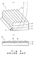
- Such a backlight unit 50 of an edge light type is equipped with a rod-shaped lamp 51 for use as a light source, an optical waveguide plate 52 having a square plate shape disposed so that the edge thereof abuts along the lamp 51, a light diffusion sheet 53 disposed to the front face side of the optical waveguide plate 52, and a prism sheet 54 disposed to the front face side of the light diffusion sheet 53, as fundamentally shown in Fig. 4A .
- this backlight unit 50 rays of incident light from the lamp 51 to the optical waveguide plate 52 are first reflected on reflection dots or a reflection sheet (not shown in the Figure) of the back face of the waveguide plate 52, and exit from the front face of the waveguide plate 52.
- the rays of light exited from the waveguide plate 52 enter into the light diffusion sheet 53, then are diffused by the light diffusion sheet 53 and exit from the front face of the light diffusion sheet 53. Thereafter, the rays of light exited from the light diffusion sheet 53 enter into the prism sheet 54, and exit as rays of light having a distribution representing a peak in a direction along a substantially normal line via a prism part 54a formed on the front face of the prism sheet 54.
- the rays of light exited from the lamp 51 are diffused by the light diffusion sheet 53, and refracted by the prism sheet 54 so that they represent a peak in a direction along the substantially normal line, and illuminate the entire face of the liquid crystal layer on the front face side (not shown in the Figure).
- a light diffusion sheet may be further disposed to the front face side of the prism sheet 54 for the purpose of: relaxation of light condensing properties of the prism sheet 54 as described above; protection of the prism part 54a; or prevention of the sticking between the prism sheet 54 and the liquid crystal panel such as a polarization plate.
- the light diffusion sheet 53 to be disposed to the backlight unit 50 generally has a transparent substrate layer 56 made of a synthetic resin, and a light diffusion layer 57 overlaid on the front face of the substrate layer 56 as shown in Fig. 4B (for example, see, JP-A Nos. H07-5305 and 2000-89007 ).
- this light diffusion layer 57 includes resin beads 59 in a transparent resin binder 58, and the beads 59 exert the light diffusion function.
- characteristics desired for LCD vary depending on their applications, but may include (a) heightening of luminance, (b) widening of viewing angle, (c) energy saving, (d) thin and light modeling, (e) price reduction (economical efficiency) capabilities and the like.
- characteristics desired for LCD vary depending on their applications, but may include (a) heightening of luminance, (b) widening of viewing angle, (c) energy saving, (d) thin and light modeling, (e) price reduction (economical efficiency) capabilities and the like.
- optical functions such as heightening of luminance, widening of viewing angle and the like, but also social needs such as price reduction, thin and light modeling capability, and the like have been increasing.
- means for increasing the amount of incorporated beads 59 and amount of the overlaid light diffusion layer 57 are generally believed to be appropriate as means for improving light diffusibility, however, such increase in amount of incorporating the beads 59 and amount of the overlaid light diffusion layer 57 may lead to difficulties in coating and decrease in transmittance of rays of light.
- the conventional general light diffusion sheet 53 employs as the beads 59, polydisperse beads that have comparatively large mean particle size of approximately 20 ⁇ m, and have comparatively broad distribution of the particle size while having the weight ratio of the beads 59 to the binder of approximately 1 and the amount of the overlaid light diffusion layer 57 of 15 to 20 g/m2.
- the aforementioned conventional light diffusion sheet 53 is formed such that hemispherical protruding parts are comparatively adjacent to the front face of the light diffusion layer 57 owing to the particle size distribution, mean particle size and amount of the beads 59. Therefore, continuous scratches may be generated on the front face of the light diffusion layer 57 in steps of producing the light diffusion sheet 53 and assembly of LCD, whereby reduction of process yield of the product may be caused. Such reduction of process yield of the product of the light diffusion sheet 53 shall be contrary to needs for price reduction of the LCD.
- An object of the present invention is to provide a light diffusion sheet according to the preamble of claim 1 having a satisfactory cost reduction capability due to high scratching preventive property of the front face, as well as a favorable directional light diffusion function, transmittivity of rays of light and a thin film character, and a backlight unit in which performances such as luminance as well as price reduction, and thin and light modeling capability are promoted.
- the invention is directed to a light diffusion sheet according to claim 1 and to a backlight unit according to claim 10.
- the light diffusion sheet has the protruding parts having a shape of a partial spherical body on the front face of the light diffusion layer in a scattering manner, possibility of scratching of the front face is reduced, and generation of a continuous scratch can be prevented even though the front face is scratched (hereinafter, this effect is referred to as "scratching preventive property").
- this effect is referred to as "scratching preventive property"
- generation of the continuous scratch on the front face can be reduced in the steps of the production and assembly of LCD. whereby reduction of the process yield of the product can be prevented.
- the beads which may be included are primary beads, herein also referred to as small beads or small monodisperse beads (monodisperse beads having a small diameter), as a principal component, and secondary beads, herein also referred to as large beads, having a mean particle size greater than the small monodisperse beads (beads having a large diameter) as a sub component.
- the light diffusion sheet can have optical functions such as a favorable directional light diffusion function, transmittivity of rays of light and the like, and economical efficiency, thin film character, coating facility and the like may be promoted.
- the protruding parts having a shape of a partial spherical body can be formed on the light diffusion layer front face of the light diffusion sheet in a scattering manner, whereby the aforementioned scratching preventive property can be sufficiently achieved.
- Mean particle size of the small monodisperse beads is 1.5 ⁇ m or greater and 5 ⁇ m or less, weight ratio of the beads to the binder is 2.5 or greater and 3 or less, and amount of the overlaid light diffusion layer is 3 g/m 2 or greater and 10 g/m 2 or less.
- Mean particle size of the large beads is 3 ⁇ m or greater and 15 ⁇ m or less, and weight ratio of the small monodisperse beads to the large beads is 6/4 or greater and 9/1 or less.
- mean height of the protruding parts be 1 ⁇ m or greater and 10 ⁇ m or less
- mean diameter of the protruding parts be 4 ⁇ m or greater and 18 ⁇ m or less
- mean occupancy rate of the protruding parts be 2% or greater and 20% or less
- surface roughness (Ra) of the light diffusion layer achieved by providing the protruding parts on the front face in a scattering manner be 1.5 ⁇ m or greater and 10 ⁇ m or less.
- the mean height of the protruding parts By thus defining the mean height of the protruding parts, mean diameter of the protruding parts, mean occupancy rate of the protruding parts and surface roughness (Ra) of the light diffusion layer to fall within the above range, the aforementioned scratching preventive property of the light diffusion sheet front face can be promoted without deteriorating the optical functions such as light diffusibility exhibited by the light diffusion layer.
- Monodisperse beads can be used as the aforementioned large beads. Such use of the monodisperse beads as the large beads enables reduction of the amount of the large beads for forming the protruding parts on the light diffusion layer front face, and thus factors which may affect the optical functions such as light diffusibility exhibited by the light diffusion layer can be minimized.
- Coefficient of variation of particle size distribution of the monodisperse beads is preferably equal to or less than 0.2.
- Use of the monodisperse beads having a coefficient of variation of particle size distribution of equal to or less than 0.2 as the small monodisperse beads in this manner may efficaciously promote the directional light diffusion function and transmittivity of rays of light exhibited by the light diffusion layer, and facility in forming the light diffusion layer having a great weight ratio of the beads and a small amount of overlay as described above can be promoted efficaciously.
- use of the monodisperse beads having a coefficient of variation of particle size distribution of equal to or less than 0.2 as the large beads enables the light diffusion sheet to have the scratching preventive property sufficiently.
- an acrylic resin may be used as the substrate polymer of the aforementioned beads and binder.
- Use of an acrylic resin as a main material for the beads and binder in this manner enables the aforementioned directional light diffusion function and transmittivity of rays of light to be further promoted.
- a sticking preventive layer overlaid on the back face side of the aforementioned substrate layer be further included, wherein this sticking preventive layer may have beads dispersed in a binder.
- the cost reduction, and thin and light modeling capability which have been presently desired in social aspects can be promoted because the light diffusion sheet has an excellent scratching preventive property, economical efficiency and thin film character as described above. Also, because the light diffusion sheet in the backlight unit has excellent directional diffusion function and transmittivity of rays of light as described above, lack in uniformity of the luminance can be reduced while the face luminance can be improved.
- the "shape of a partial spherical body” means a shape like a part of a spherical body.
- the spherical body falls into the category which may include e.g., spheroid, polyhedron and the like, but not limited to a perfect spherical body.
- the term "mean height of the protruding parts” means an average height of protruding parts measured with respect to a face of an average height in the region without having any protruding parts of the light diffusion layer front face, as a base level.
- the “mean diameter of the protruding parts” means an average value of the width in the front face shape of the protruding part as measured in predetermined two-orthogonal directions.
- the "mean occupancy rate of the protruding parts” means an average value of area ratio occupied by the protruding parts in the light diffusion layer front face.
- the “mean particle size” and the “coefficient of variation” are values represented on the
- the light diffusion sheet of the present invention has a favorable cost reduction capability due to excellent scratching preventive property of the front face, and has in addition thereto, a favorable directional light diffusion function, transmittivity of rays of light, and a thin film character. Also, according to the backlight unit of the present invention, price reduction, and thin and light modeling capability can be promoted, and optical performances such as luminance, uniformity of the luminance and the like can be improved.
- a light diffusion sheet 1 shown in Fig. 1 comprises a substrate layer 2, and a light diffusion layer 3 overlaid on the front face of this substrate layer 2.
- the substrate layer 2 is formed from a transparent, particularly, colorless and transparent synthetic resin, because transmission of rays of light is required.
- the synthetic resin which may be used for the substrate layer 2 is not particularly limited, but examples thereof include e.g., polyethylene terephthalate, polyethylene naphthalate, acrylic resins, polycarbonate, polystyrene, polyolefin, cellulose acetate, weather resistant vinyl chloride, and the like. Among them, polyethylene terephthalate having excellent transparency and high strength is preferred, and polyethylene terephthalate with improved deflection property is particularly preferred.
- the thickness of the substrate layer 2 (mean thickness) is not particularly limited, it may be preferably 10 ⁇ m or greater and 250 ⁇ m or less, and particularly preferably 20 ⁇ m or greater and 188 ⁇ m or less.
- the thickness of the substrate layer 2 is less then the above range, disadvantages are raised such as liability to occurrence of curling upon coating of the polymer composition for forming the light diffusion layer 3, and difficulties in handling thereof.
- the thickness of the substrate layer 2 is greater than the above range, luminance of a liquid crystal display device may be lowered, and the thickness of a backlight unit becomes so great that a result that is adverse to demands for thin and light modeling of a liquid crystal display device may be also effected.
- the light diffusion layer 3 comprises beads 4 laid to spread over the front face of the substrate layer 2 in a substantially uniform and compact manner, and a binder 5 that fixes the beads 4. Such beads 4 are covered by the binder 5.
- the beads 4 included in the light diffusion layer 3 in such a manner enable uniform diffusion of rays of light which transmit the light diffusion layer 3 from the back side to the front side.
- fine protrusions are formed on the surface of the light diffusion layer 3 in a substantially uniform and substantially compact manner. Owing to a refracting action of the fine recessions and protrusions like a lens thus formed on the front face of the light diffusion sheet 1, the rays of light can be more efficiently diffused.
- the beads 4 are approximately spherical transparent particles having a property to permit diffusion of rays of light.
- the material which may be used for forming the beads 4 include e.g., acrylic resins, acrylonitrile resins, urethane based resins, vinyl chloride based resins, styrene based resins, polyamide, silicone based resins, fluorine based resins and the like.
- acrylic resins having high transparency are preferred, and in particular, polymethyl methacrylate (PMMA) is preferred.
- Exemplary acrylic resins described above may include acryl-styrene based copolymer resins, acryl-urethane based copolymer resins, acryl-fluorine based copolymer resins, acryl-silicone based copolymer resins and the like.
- small monodisperse beads 4a as a principal component having a comparatively small particle size
- large beads 4b as a sub component having a mean particle size greater than that of the small monodisperse beads 4a are included.
- the monodisperse beads mean beads having a high uniformity ratio of the particle size.
- the lower limit of mean height H of the protruding parts 6 is preferably 1 ⁇ m, particularly 2 ⁇ m, and more particularly 3 ⁇ m.
- the upper limit of the mean height H of the protruding parts 6 is preferably 10 ⁇ m, particularly 7 ⁇ m, and more particularly 5 ⁇ m.
- the mean height H of the protruding parts 6 is greater than the above upper limit, optical functions such as light diffusibility exhibited by the small monodisperse beads 4a may be deteriorated, whereby reduction in luminance and lack in uniformity of the luminance may be caused.
- the lower limit of mean diameter D of the protruding parts 6 is preferably 4 ⁇ m, particularly 8 ⁇ m, and more particularly 10 ⁇ m.
- the upper limit of the mean diameter D of the protruding parts 6 is preferably 18 ⁇ m, particularly 15 ⁇ m, and more particularly 12 ⁇ m.
- the mean diameter D of the protruding parts 6 is greater than the above upper limit, optical functions such as light diffusibility exhibited by the small monodisperse beads 4a may be deteriorated, whereby reduction in luminance and lack in uniformity of the luminance may be caused.
- the lower limit of mean occupancy rate of the protruding parts 6 is preferably 2%, particularly 2.5%, and more particularly 3.5%.
- the upper limit of the mean occupancy rate of the protruding parts 6 is preferably 20%, particularly 11%, and more particularly 7%.
- scratching preventive property of the light diffusion sheet 1 may not be efficaciously achieved which can result from the protruding parts 6.
- the mean occupancy rate of the protruding parts 6 is greater than the above upper limit, optical functions such as light diffusibility exhibited by the small monodisperse beads 4a may be deteriorated, whereby reduction in luminance and lack in uniformity of the luminance may be caused.
- the lower limit of surface roughness (Ra) of the light diffusion layer 3 is preferably 1.5 ⁇ m, particularly 3 ⁇ m, and more particularly 6 ⁇ m.
- the upper limit of the surface roughness (Ra) of the light diffusion layer 3 is preferably 10 ⁇ m.
- the lower limit of the mean particle size of the small monodisperse beads 4a is preferably 1.5 ⁇ m, and particularly preferably 1.8 ⁇ m.
- the upper limit of the mean particle size of the small monodisperse beads 4a is preferably 5 ⁇ m, and particularly preferably 4 ⁇ m.
- the mean particle size of the small monodisperse beads 4a is greater than the above upper limit, formation of the light diffusion layer 3 having a great weight ratio of the beads 4 to the binder 5 and a small amount of overlay may be difficult, which may lead to occurrence of defects in coating.
- Coefficient of variation of particle size distribution of the small monodisperse beads 4a is preferably equal to or less than 0.2, and particularly preferably equal to or less than 0.1.
- the coefficient of variation of particle size distribution of the small monodisperse beads 4a falling within the aforementioned range may promote facility in forming the light diffusion layer 3 having a great weight ratio of the beads 4a to the binder 5 and a small amount of overlay, whereby the directional light diffusion function of the light diffusion sheet 1 may be promoted.
- the lower limit of the mean particle size of the large beads 4b is preferably 3 ⁇ m, particularly 5 ⁇ m, and more particularly 7 ⁇ m.
- the upper limit of the mean particle size of the large beads 4b is preferably 15 ⁇ m, particularly 12 ⁇ m, and more particularly 10 ⁇ m.
- the mean particle size of the large beads 4b is greater than the above upper limit, optical functions such as light diffusibility exhibited by the small monodisperse beads 4a may be deteriorated, whereby reduction in luminance and lack in uniformity of the luminance may be caused.
- the lower limit of the weight ratio of the small monodisperse beads 4a to the large beads 4b is preferably 6/4, and particularly preferably 8/2.
- the upper limit of the weight ratio of the small monodisperse beads 4a to the large beads 4b is preferably 9/1.
- the weight ratio of the small monodisperse beads 4a to the large beads 4b is less than the above lower limit, optical functions such as light diffusibility exhibited by the small monodisperse beads 4a may be deteriorated, whereby reduction in luminance and lack in uniformity of the luminance may be caused.
- the weight ratio of the small monodisperse beads 4a to the large beads 4b is greater than the above upper limit, scratching preventive property of the light diffusion sheet 1 front face may not be efficaciously achieved.
- the large beads 4b monodisperse beads and/or polydisperse beads are used.
- the monodisperse beads are used as the large beads 4b, amount of the large beads 4b for forming the protruding parts 6 on the light diffusion layer 3 front face can be reduced, and thus factors which may affect the optical functions such as light diffusibility exhibited by the small monodisperse beads 4a can be minimized.
- the polydisperse beads are used as the large beads 4b, great particle size distribution can be achieved, whereby continuity of the scratch becomes further invisible.
- the coefficient of variation of particle size distribution thereof is preferably similar to that of the small monodisperse beads 4a described above.
- the coefficient of variation of particle size distribution is preferably 25 or greater and 45 or less, and particularly 30 or greater and 40 or less
- particle size distribution width is preferably 1 ⁇ m or greater and 30 ⁇ m or less, and particularly 3 ⁇ m or greater and 25 ⁇ m or less.
- the weight ratio of the beads 4 to the binder 5 (weight ratio of the beads 4 to the substrate polymer of the binder 5 which is calculated on the basis of the solid content) is preferably 2.5 or greater and 3 or less.
- weight ratio of the beads 4 to the binder 5 is less than the above range, the amount of the overlaid light diffusion layer 3 becomes so small as described later that light diffusibility may be insufficient.
- the weight ratio of the beads 4 to the binder 5 is beyond the above range, the effect to fix the beads 4 may be impaired, which may lead to occurrence of defects in coating.
- the binder 5 can be formed by allowing a polymer composition containing a substrate polymer to be crosslinked and cured. This binder 5 disposes and fixes the beads 4 on the front face of the substrate layer 2 in a manner to provide substantially uniform density. Furthermore, for example, a fine inorganic filler, a curing agent, a plasticizer, a dispersant, any of various levelling agents, an ultraviolet ray-absorbing agent, an anti-oxidizing agent, a viscosity improving agent, a lubricant, a light stabilizer and the like may be blended ad libitum in addition to the substrate polymer in the polymer composition for forming this binder 5.
- the aforementioned substrate polymer is not particularly limited, but examples thereof include e.g., acrylic resins, urethane based resins, polyester based resins, fluorine based resins, silicone based resins, polyamide imide, epoxy based resins, ultraviolet-curable resins and the like.
- acrylic resins urethane based resins
- polyester based resins fluorine based resins
- silicone based resins polyamide imide
- epoxy based resins epoxy based resins
- ultraviolet-curable resins and the like one or two or more of these polymers may be used as a mixture.
- a highly processable polyol that can be readily formed into the light diffusion layer 3 by a means such as coating or the like is preferred as the substrate polymer.
- the substrate polymer per se which may be used for the binder 5 is preferably transparent, and particularly preferably transparent and colorless in light of improvement of the transmittivity of the rays of light.
- polyols examples include e.g., polyols obtained by polymerizing a monomer component including a hydroxyl group-containing unsaturated monomer, polyester polyols obtained under a condition with excessive hydroxyl groups present, and the like. These may be used alone or two or more of them may be used as a mixture.
- hydroxyl group-containing unsaturated monomer examples include (a) hydroxyl group-containing unsaturated monomers such as e.g., 2-hydroxyethyl acrylate, 2-hydroxypropyl acrylate, 2-hydroxyethyl methacrylate, 2-hydroxypropyl methacrylate, allyl alcohol, homoallyl alcohol, cinnamic alcohol, and crotonyl alcohol, and (b) hydroxyl group-containing unsaturated monomers obtained by a reaction of a dihydric alcohol or an epoxy compound such as e.g., ethylene glycol, ethylene oxide, propylene glycol, propylene oxide, butylene glycol, butylene oxide, 1,4-bis(hydroxymethyl)cyclohexane, phenylglycidyl ether, glycidyl decanoate or PRACCEL FM-1 (manufactured by Daicel Chemical Industries, Ltd.), with an unsaturated carboxylic acid such as e.g., acrylic acid, methoxy
- the polyol can be also manufactured by polymerizing one or two or more ethylenic unsaturated monomers selected from ethyl acrylate, n-propyl acrylate, isopropyl acrylate, n-butyl acrylate, tert-butyl acrylate, ethylhexyl acrylate, ethyl methacrylate, n-propyl methacrylate, isopropyl methacrylate, n-butyl methacrylate, tert-butyl methacrylate, ethylhexyl methacrylate, glycidyl methacrylate, cyclohexyl methacrylate, styrene, vinyltoluene, 1-methylstyrene, acrylic acid, methacrylic acid, acrylonitrile, vinyl acetate, vinyl propionate, vinyl stearate, allyl acetate, diallyl adipate, diallyl
- the polymer obtained by polymerizing the monomer component comprising the hydroxyl group-containing unsaturated monomer may have a number average molecular weight of 1000 or greater and 500000 or less, and preferably 5000 or greater and 100000 or less. Furthermore, the hydroxyl value may be 5 or greater and 300 or less, preferably 10 or greater and 200 or less, and more preferably 20 or greater and 150 or less.
- the polyester polyol obtained under a condition with excessive hydroxyl groups present can be manufactured by allowing a reaction of (c) a polyhydric alcohol such as e.g., ethylene glycol, diethylene glycol, propylene glycol, dipropylene glycol, 1,3-butanediol, 1,4-butanediol, 1,5-pentanediol, neopentyl glycol, hexamethylene glycol, decamethylene glycol, 2,2,4-trimethyl-1,3-pentanediol, trimethylolpropane, hexanetriol, glycerin, pentaerythritol, cyclohexanediol, hydrogenated bisphenol A, bis(hydroxymethyl)cyclohexane, hydroquinone bis(hydroxyethyl ether), tris(hydroxyethyl)isocyanurate or xylylene glycol with (d) a polybasic acid such as e
- Number average molecular weight of the polyol obtained under the condition with excessive hydroxyl groups present may be 500 or greater and 300000 or less, and more preferably 2000 or greater and 100000 or less. Additionally, the hydroxyl value may be 5 or greater and 300 or less, preferably 10 or greater and 200 or less, and more preferably 20 or greater and 150 or less.
- the polyol for use as the substrate polymer of the polymer composition may be preferably an acryl polyol which is obtained by polymerizing the aforementioned polyester polyol, and a monomer component comprising the hydroxyl group-containing unsaturated monomer, and which has a (meth)acrylic unit or the like.
- the binder 5 including the polyester polyol or acryl polyol as the substrate polymer is highly transparent and weather resistant, and yellowing of the light diffusion layer 3 and the like can be suppressed.
- use of the acryl polyol as the substrate polymer, and use of the acrylic resin beads 4 will reduce unwanted refraction, reflection and the like at the interface of the beads 4.
- the optical functions such as the directional light diffusion function, transmittivity of rays of light and the like of the light diffusion sheet 1 can be improved.
- Either one of this polyester polyol or the acryl polyol may be used, alternatively, both of them may be used.
- Number of the hydroxyl groups in the polyester polyol and the acryl polyol is not particularly limited as long as it is two or more per molecule, however, when the hydroxyl value in the solid content is equal to or less than 10, crosslinking points may be reduced and thus, film physical properties such as solvent resistance, water resistance, heat resistance, surface hardness and the like are liable to be decreased.
- the lower limit of the amount of the overlaid light diffusion layer 3 may be preferably 3 g/m 2 , and particularly preferably 5 g/m 2 .
- the upper limit of the amount of the overlaid light diffusion layer 3 may be preferably 10 g/m 2 , and particularly preferably 8 g/m 2 .
- the beads 4 can be laid to spread over the front face of the substrate layer 2 in a comparatively compact and uniform manner, thereby capable of forming fine protrusions on the front face of the light diffusion layer 3 in a comparatively compact and uniform manner. Consequently, the optical functions such as a directional light diffusion function, transmittivity of rays of light and the like of the light diffusion sheet 1 can be improved.
- the small monodisperse beads 4a with uniform particle size can be laid to spread over the front face of the substrate layer 2 in a comparatively compact and uniform manner, thereby capable of forming protrusions that are fine and have uniform height on the front face in a comparatively compact and uniform manner by using the small monodisperse beads 4a with a small particle size, setting the weight ratio of the beads to the binder to be great, and setting the amount of the overlaid light diffusion layer 3 to be small as described above.
- the light diffusion sheet 1 has a favorable directional light diffusion function, transmittivity of rays of light and the like, thereby capable of promoting the economic efficiency and thin film character.
- the light diffusion sheet 1 has protruding parts 6 having a shape of a partial spherical body on the front face of the light diffusion layer 3 in a scattering manner through including the large beads 4b as a sub component of the beads 4, therefore, possibility of scratching of the front face is reduced, and generation of a continuous scratch can be prevented even though the front face is scratched.
- generation of continuous scratches on the front face can be reduced in the steps of the production and assembly of LCD, whereby reduction of the process yield of the product can be prevented.
- the light diffusion sheet 1 it is most suitable that: an acrylic resin be used as the substrate polymer of the beads 4 and the binder 5; mean particle size of the small monodisperse beads 4a be 3 ⁇ m; the weight ratio of the beads 4 to the binder 5 be 2.7; and the amount of the overlaid light diffusion layer 3 be 6 g/m 2 . Accordingly, the directional light diffusion function, transmittivity of rays of light, economic efficiency, thin film character and the like of the light diffusion sheet 1 can be efficiently improved.
- a fine inorganic filler may be included in the polymer composition that forms the binder 5.
- the heat resistance of the light diffusion layer 3, and in turn, of the light diffusion sheet 1 may be improved.
- Inorganic matter that constitutes this fine inorganic filler is not particularly limited, but inorganic oxides are preferred.
- This inorganic oxide is defined as any one of a variety of oxygen-containing metal compounds in which a metal element forms a three dimensional network predominantly via bonds with an oxygen atom.
- the metal element that constitutes the inorganic oxide is preferably an element selected from, for example, the group II- VI in a periodic table of the elements, and more preferably an element selected from the group III - V in periodic table of the elements.
- an element selected from Si, Al, Ti and Zr is preferred.
- Colloidal silica in which the metal element is Si is most preferred as the fine inorganic filler in terms of the effect to improve the heat resistance and uniform dispersibility.
- the shape of the fine inorganic filler is not particularly limited, but may be any optional particle shape such as spherical, needle-like, plate-like, squamous, granular or the like.
- the lower limit of the mean particle size of the fine inorganic filler is preferably 5 nm, and particularly preferably 10 nm.
- the upper limit of the mean particle size of the fine inorganic filler is preferably 50 nm, and particularly preferably 25 nm.
- the lower limit of the weight ratio of the fine inorganic filler (weight ratio of the inorganic substance component alone per 100 parts by weight of the substrate polymer of the binder 5) is preferably 5 parts, and particularly preferably 50 parts calculated on the basis of the solid content.
- the upper limit of the weight ratio of the fine inorganic filler is preferably 500 parts, more preferably 200 parts, and particularly preferably 100 parts.
- the fine inorganic filler one having an organic polymer fixed on the surface thereof may be used.
- the organic polymer-fixed fine inorganic filler dispersibility in the binder 5 and improvement of affinity with the binder 5 may be contemplated.
- This organic polymer is not particularly limited with respect to the molecular weight, shape, composition, presence of the functional group and the like, but an arbitrary organic polymer may be used.
- any arbitrary shape such as a straight, branched or crosslinked structure may be used.
- the resin constituting the organic polymer include e.g., (meth)acrylic resins, polystyrene, polyvinyl acetate, polyolefin such as polyethylene and polypropylene, polyvinyl chloride, polyvinylidene chloride, polyesters such as polyethylene terephthalate, copolymers of the same as well as these resins partially modified with a functional group such as an amino group, an epoxy group, a hydroxyl group or a carboxyl group, or the like.
- a functional group such as an amino group, an epoxy group, a hydroxyl group or a carboxyl group, or the like.
- those including an organic polymer which contains a (meth)acrylic unit such as a (meth)acrylic resin, a (meth)acryl-styrene based resin or a (meth)acryl-polyester based resin as an essential component are suited because of their film formation ability.
- resins having miscibility with the substrate polymer of the aforementioned polymer composition are preferred, therefore, that having the same composition as the substrate polymer included in the polymer composition is most preferred.
- the fine inorganic filler may include an organic polymer within the fine particle. Accordingly, adequate softness and toughness can be imparted to the inorganic substance that is a core of the fine inorganic filler.
- organic polymer those containing an alkoxy group may be preferably used, with the content of the same being 0.01 mmol or greater and 50 mmol or less per gram of the fine inorganic filler to which the organic polymer was fixed.
- an alkoxy group can improve affinity with a matrix resin that constitutes the binder 5, and dispersibility in the binder 5.
- the alkoxy group described above means an RO group bound to a metal element that forms the skeleton of the fine particle.
- R herein represents an alkyl group which may be substituted, and the RO group in the fine particle may be the same or different. Specific examples of R include methyl, ethyl, n-propyl, isopropyl, n-butyl and the like. It is preferred that a metal alkoxy group be used which comprises the same metal as that constituting the fine inorganic filler. When the fine inorganic filler is colloidal silica, an alkoxy group including silicon as the metal may be preferably used.
- percentage content of the organic polymer in the fine inorganic filler to which the organic polymer was fixed is not particularly limited, the content thereof is preferably equal to or greater than 0.5% by weight and equal to or less than 50% by weight based on the fine organic filler.
- an organic polymer having a hydroxyl group is used as the organic polymer to be fixed on the fine inorganic filler, and that at least one selected from polyfunctional isocyanate compounds having two or more functional groups that react with a hydroxyl group, melamine compounds and aminoplast resins is included in the polymer composition that constitutes the binder 5. Accordingly, the fine inorganic filler and the matrix resin of the binder 5 are bound via a crosslinking structure, leading to excellent stability upon preservation, stain resistance, flexibility, weather resistance and the like. Furthermore, the resulting coated film can be glossy.
- a polyol having a cycloalkyl group is preferred as the substrate polymer of the binder 5.
- hydrophobicity of the binder 5 may be elevated to improve water repellency, water resistance and the like. Accordingly, deflection resistance, size stability and the like of the light diffusion sheet 1 under high temperature and high humidity conditions can be improved. Additionally, basic film coating performances such as weather resistance, hardness, bulky feeling, solvent resistance and the like of the light diffusion layer 3 may be improved.
- affinity with the fine inorganic filler to which the organic polymer was fixed on the surface thereof, and uniform dispersibility of the fine inorganic filler may be further favorable.
- the cycloalkyl group is not particularly limited, but examples thereof include e.g., cyclobutyl groups, cyclopentyl groups, cyclohexyl groups, cycloheptyl groups, cyclooctyl groups, cyclononyl groups, cyclodecyl groups, cycloundecyl groups, cyclododecyl groups, cyclotridecyl groups, cyclotetradecyl groups, cyclopentadecyl groups, cyclohexadecyl groups, cycloheptadecyl groups, cyclooctadecyl groups and the like.
- the polyol having the cycloalkyl group is obtained by copolymerization of a polymerizable unsaturated monomer having a cycloalkyl group.
- a polymerizable unsaturated monomer having a cycloalkyl group is a polymerizable unsaturated monomer having at least one cycloalkyl group within the molecule.
- This polymerizable unsaturated monomer is not particularly limited, but examples thereof include e.g., cyclohexyl(meth)acrylate, inethylcyclohexyl(meth)acrylate, tert-butylcyclohexyl(meth)acrylate, cyclododecyl(meth)acrylate and the like.
- isocyanate may be included as a curing agent in the polymer composition.
- an isocyanate curing agent in the polymer composition, even more rigid crosslinking structure is provided, thereby further improving the physical film properties of the light diffusion layer 3.
- Similar substance to the polyfunctional isocyanate compounds as described above may be used as the isocyanate. Among them, aliphatic isocyanate is preferred which prevents the coated film from yellowing.
- any one of hexamethylene diisocyanate, isophorone diisocyanate and xylene diisocyanate, or two or more thereof as a mixture may be used as the curing agent to be blended in the polymer composition.
- velocity of the curing reaction of the polymer composition is elevated, therefore, lowering of the velocity of the curing reaction due to the cationic antistatic agent can be sufficiently compensated even though a cationic substance that is responsible for dispersion stability of the fine inorganic filler is used as the antistatic agent.
- the light diffusion sheet 1 can markedly suppress deflection and yellowing due to heat, ultraviolet ray and the like.
- an antistatic agent may be included in the aforementioned polymer composition.
- the light diffusion sheet 1 exerts an antistatic effect, thereby enabling the prevention of disadvantages resulting from electrostatic charge such as attraction of dust, getting into a difficulty in overlaying with a prism sheet or the like, and the like.
- coating the antistatic agent on a surface results in stickiness or pollution of the surface, such negative effects may be reduced by mixing it in the polymer composition.
- This antistatic agent is not particularly limited, but examples of the antistatic agents which may be used include e.g., anionic antistatic agents such as alkyl sulfate, alkyl phosphate and the like; cationic antistatic agents such as quaternary ammonium salts, imidazoline compounds and the like; nonionic antistatic agents such as polyethyleneglycol based compounds, polyoxyethylene sorbitan monostearate esters, ethanol amides and the like; polymeric antistatic agents such as polyacrylic acid and the like; ion conductive antistatic agents and the like.
- anionic antistatic agents such as alkyl sulfate, alkyl phosphate and the like
- cationic antistatic agents such as quaternary ammonium salts, imidazoline compounds and the like
- nonionic antistatic agents such as polyethyleneglycol based compounds, polyoxyethylene sorbitan monostearate esters, ethanol amides and the like
- polymeric antistatic agents such as polyacryl
- an ultraviolet ray-absorbing agent may be included in the polymer composition.
- an ultraviolet protection function may be imparted to the light diffusion sheet 1, thereby protecting a slight amount of an ultraviolet ray emitted from the lamp of the backlight unit. Accordingly, disruption of the liquid crystal layer due to the ultraviolet ray can be prevented.
- the ultraviolet ray-absorbing agent is not particularly limited, but any known one may be used as long as it absorbs an ultraviolet ray and efficiently converts it into heat energy, and is a compound that is stable to the light.
- salicylic acid based ultraviolet ray-absorbing agents benzophenone based ultraviolet ray-absorbing agents, benzotriazole based ultraviolet ray-absorbing agents and cyano acrylate based ultraviolet ray-absorbing agents are preferred which have high ultraviolet ray-absorbing function and favorable miscibility with the aforementioned substrate polymer, and can be stably present in the substrate polymer.
- One or two or more agents selected from these groups may be used.
- a polymer having an ultraviolet ray-absorbing group in the molecular chain for example, "UW UV” series of NIPPON SHOKUBAI Co., Ltd., and the like
- a polymer having an ultraviolet ray-absorbing group in the molecular chain high miscibility with the main polymer of the binder 5 may be achieved, and deterioration of the ultraviolet ray-absorbing function caused by bleeding out of the ultraviolet ray-absorbing agent can be prevented.
- a polymer having an ultraviolet ray-absorbing group in the molecular chain can be used as the substrate polymer of the binder 5. Additionally, using the polymer to which the ultraviolet ray-absorbing group was bound as the substrate polymer of the binder 5, and including an ultraviolet ray-absorbing agent in this substrate polymer may be also permitted, thereby capable of further improving the ultraviolet ray-absorbing function.
- the lower limit of the content of the ultraviolet ray-absorbing agent to the substrate polymer of the binder 5 is preferably 0.1% by weight, more preferably 1% by weight, and still more preferably 3% by weight, while the upper limit of the content of the ultraviolet ray-absorbing agent is preferably 10% by weight, more preferably 8% by weight, and still more preferably 5% by weight.
- the weight ratio of the ultraviolet ray-absorbing agent to the substrate polymer is less than the above lower limit, the ultraviolet ray-absorbing function of the light diffusion sheet 1 may not be efficaciously achieved, in contrast, when the weight ratio of the ultraviolet ray-absorbing agent is greater than the above upper limit, deleterious influence may be exerted on the substrate polymer, which may lead to reduction in the strength, durability and the like of the binder 5.
- an ultraviolet ray-stabilizing agent (including substrate polymer having an ultraviolet ray-stabilizing group bound to the molecular chain) can be also used.
- This ultraviolet ray-stabilizing agent may inactivate the radical, active oxygen and the like generated by the ultraviolet ray, thereby capable of improving the ultraviolet ray stability, weather resistance and the like.
- a hindered amine based ultraviolet ray-stabilizing agent that is highly stable to ultraviolet rays may be suitably used.
- use of the ultraviolet ray-absorbing agent and the ultraviolet ray-stabilizing agent in combination markedly improves prevention of deterioration due to the ultraviolet rays and weather resistance.
- the process for producing the light diffusion sheet 1 includes: (a) a step of preparing a polymer composition for a light diffusion layer through admixing beads 4 with a polymer composition that constitutes a binder 5; and (b) a step of overlaying and curing the polymer composition for a light diffusion layer on a front face of a substrate layer 2 to form a light diffusion layer 3.
- the means for overlaying the polymer composition for the light diffusion layer is not particularly limited, but any of various known methods may be employed. Specific means for overlaying which may be employed involves coating in which e.g., a gravure coating method, a roll coating method, a bar coating method, a blade coating method, a spray coating method or the like is used. Among all, a gravure coating method which enables the polymer composition having a great weight ratio of the beads 4 to be coated to give a thin and even film is most preferred. In such a gravure coating method, taking into consideration of the formation performance of the light diffusion layer 3, number of lines of the gravure may be 70 or greater and 100 or less, and the rotation number may be preferably 80 or greater and 120 or less.
- a light diffusion sheet 11 illustrated in Fig. 2 has a substrate layer 2, a light diffusion layer 3 overlaid on the front face of this substrate layer 2, and a sticking preventive layer 12 overlaid on the back face of this substrate layer 2. Because the substrate layer 2 and the light diffusion layer 3 are similar to those in the light diffusion sheet 1 shown in Fig. 1 as described above, explanation thereof is omitted by way of assigning the identical numeric number.
- the sticking preventive layer 12 includes beads 13 disposed on the back face of the substrate layer 2, and a binder 14 that fixes the beads 13.
- This binder 14 is also formed by crosslinking and curing a polymer composition which is similar to that for the binder 5 of the light diffusion layer 3 as described above.
- the material for the beads 13 similar ones to the beads 4 for the light diffusion layer 3 may be used.
- the thickness of the sticking preventive layer 12 is not particularly limited, however for example, it is set to be around 1 ⁇ m or greater and 10 ⁇ m or less.
- the weight ratio of the beads 13 is set to be relatively small.
- the beads 13 are dispersed in the binder 14 spacing apart with each other.
- a small bottom part of many of the beads 13 may be protruded from the mean interface of the binder 14 to form protrusions on the back face of the sticking preventive layer 12.
- the process for producing the light diffusion sheet 11 includes: (a) a step of preparing a polymer composition for a light diffusion layer through admixing beads 4 with a polymer composition that constitutes a binder 5; (b) a step of overlaying and curing the polymer composition for a light diffusion layer on a front face of a substrate layer 2 to form a light diffusion layer 3; (c) a step of preparing a polymer composition for a sticking preventive layer through admixing beads 13 with a polymer composition that constitutes a binder 13; and (d) a step of overlaying and curing the polymer composition for a sticking preventive layer on the back face of the substrate layer 2 to overlay a sticking preventive layer 12.
- Means for overlaying the polymer composition for a light diffusion layer and the polymer composition for a sticking preventive layer on the substrate layer 2 is not particularly limited, but, for example, coating in which a bar coater, a blade coater, a spin coater, a roll coater, a gravure coater, a flow coater, a spray or the like is used may be employed.
- the light diffusion sheet 11 can form, similarly to the light diffusion sheet 1 as described above, protrusions that are fine and have uniform height in a comparatively compact and uniform manner on the front face. Consequently, it has a favorable directional light diffusion function, transmittivity of rays of light and the like, and can promote the economic efficiency and thin film characters.
- the light diffusion sheet 11 has, similarly to the light diffusion sheet 1 described above, the protruding parts 6 having a shape of a partial spherical body on the front face of the light diffusion layer 3 in a scattering manner, therefore, it has a scratching preventive property on the front face, whereby reduction of the process yield of the product can be prevented.
- a backlight unit for use in a liquid crystal display device which is equipped with a lamp, an optical waveguide plate, a light diffusion sheet, a prism sheet and the like, where rays of light emitted from the lamp are diffused to lead to the front face side
- qualities such as face luminance, uniformity of the luminance and the like can be improved owing to its high directional light diffusion function, transmittivity of rays of light, thin film character, economic efficiency and the like as described above, and additionally, reduction in cost, and thin and light modeling capability can be promoted which have been presently desired in social aspects.
- the light diffusion sheet 1 or 11 has an excellent scratching preventive property, cost reduction capability and thin film character in the backlight unit as described above, reduction in cost, and thin and light modeling capability can be promoted which have been presently desired in social aspects.
- the light diffusion sheet of the present invention is not limited to the foregoing embodiments.
- a variety of modes in which protruding parts having a shape of a partial spherical body on the front face of the light diffusion layer in a scattering manner may be employed.
- means for forming the protruding parts on the light diffusion layer front face by incorporating a filler other than the beads into the light diffusion layer, means for forming the protruding parts by transcription using a sheet pattern, and the like may be employed.
- other layers such as an ultraviolet ray-absorbing agent layer, top coat layer and the like may be also overlaid on the light diffusion sheet.
- the ultraviolet ray-absorbing agent in place of or together with the aforementioned means for incorporating into the binder of the light diffusion layer, it is also possible to overlay the ultraviolet ray-absorbing layer including an ultraviolet ray-absorbing agent can be also overlaid, alternatively, the ultraviolet ray-absorbing agent can be also included in the binder of the sticking preventive layer or in the substrate layer. Also by these means, protection of the backlight unit from the ultraviolet ray emitted from the lamp can be similarly executed, and disruption of the liquid crystal layer due to the ultraviolet ray can be prevented.
- an antistatic layer including an antistatic agent can be also overlaid, and the antistatic agent can be also included in the binder of the sticking preventive layer or in the substrate layer.
- the antistatic effect may be developed to the light diffusion sheet, therefore, occurrence of disadvantages caused due to electrification, such as collecting dusts with friction, difficulties in overlaying with other sheet such as a prism sheet or the like can be prevented.
- a transparent polyethylene terephthalate film having a thickness of 100 ⁇ m was used as a substrate layer.
- a polymer composition comprising 32 parts of an acryl polyol (substrate polymer), 86 parts of beads made of an acrylic resin, 6 parts of an isocyanate based curing agent, 3 parts of an antistatic agent and a solvent was used as a polymer composition for a light diffusion layer. Number of the parts representing the amount of each component means the weight ratio calculated on the basis of the solid content.
- the beads only small monodisperse beads having a mean particle size of 3 ⁇ m and a coefficient of variation of 0.1 were used.
- a light diffusion sheet of Comparative Example was obtained by laminating the polymer composition for a light diffusion layer on the front face of the substrate layer in an amount of 6 g/m 2 (calculated on the basis of the solid content) by a gravure coating method.
- a light diffusion sheet of Example 1 was obtained in a similar manner to the above Comparative Example except that the small monodisperse beads and large beads were used as the beads after mixing.
- the used large beads were polydisperse beads having a mean particle size of 8.6 ⁇ m, a coefficient of variation of 33.5, and a particle size distribution width of 3.2 ⁇ m or greater and 23.8 ⁇ m or less.
- the weight ratio of the small monodisperse beads to the large beads was 95/5.
- a light diffusion sheet of Example 2 was obtained in a similar manner to the above Comparative Example except that the small monodisperse beads and large beads were used as the beads after mixing.
- the used large beads were polydisperse beads having a mean particle size of 8.6 ⁇ m, a coefficient of variation of 33.5, and a particle size distribution width of 3.2 ⁇ m or greater and 23.8 ⁇ m or less.
- the weight ratio of the small monodisperse beads to the large beads was 9/1.
- a light diffusion sheet of Example 3 was obtained in a similar manner to the above Comparative Example except that the small monodisperse beads and large beads were used as the beads after mixing.
- the used large beads were polydisperse beads having a mean particle size of 8.6 ⁇ m, a coefficient of variation of 33.5, and a particle size distribution width of 3.2 ⁇ m or greater and 23.8 ⁇ m or less.
- the weight ratio of the small monodisperse beads to the large beads was 8/2.
- a light diffusion sheet of Example 4 was obtained in a similar manner to the above Comparative Example except that the small monodisperse beads and large beads were used as the beads after mixing.
- the used large beads were polydisperse beads having a mean particle size of 8.6 ⁇ m, a coefficient of variation of 33.5, and a particle size distribution width of 3.2 ⁇ m or greater and 23.8 ⁇ m or less.
- the weight ratio of the small monodisperse beads to the large beads was 7/3.
- a light diffusion sheet of Example 5 was obtained in a similar manner to the above Comparative Example except that the small monodisperse beads and large beads were used as the beads after mixing.
- the used large beads were polydisperse beads having a mean particle size of 8.6 ⁇ m, a coefficient of variation of 33.5, and a particle size distribution width of 3.2 ⁇ m or greater and 23.8 ⁇ m or less.
- the weight ratio of the small monodisperse beads to the large beads was 6/4.
- a light diffusion sheet of Example 6 was obtained in a similar manner to the above Comparative Example except that the small monodisperse beads and large beads were used as the beads after mixing.
- the used large beads were polydisperse beads having a mean particle size of 8.6 ⁇ m, a coefficient of variation of 33.5, and a particle size distribution width of 3.2 ⁇ m or greater and 23.8 ⁇ m or less.
- the weight ratio of the small monodisperse beads to the large beads was 5/5.
- a light diffusion sheet of Example 7 was obtained in a similar manner to the above Comparative Example except that the small monodisperse beads and large beads were used as the beads after mixing.
- the used large beads were monodisperse beads having a mean particle size of 8 ⁇ m.
- the weight ratio of the small monodisperse beads to the large beads was 95/5.
- a light diffusion sheet of Example 8 was obtained in a similar manner to the above Comparative Example except that the small monodisperse beads and large beads were used as the beads after mixing.
- the used large beads were monodisperse beads having a mean particle size of 8 ⁇ m.
- the weight ratio of the small monodisperse beads to the large beads was 9/1.
- a light diffusion sheet of Example 9 was obtained in a similar manner to the above Comparative Example except that the small monodisperse beads and large beads were used as the beads after mixing.
- the used large beads were monodisperse beads having a mean particle size of 8 ⁇ m.
- the weight ratio of the small monodisperse beads to the large beads was 8/2.
- a light diffusion sheet of Example 10 was obtained in a similar manner to the above Comparative Example except that the small monodisperse beads and large beads were used as the beads after mixing.
- the used large beads were monodisperse beads having a mean particle size of 8 ⁇ m.
- the weight ratio of the small monodisperse beads to the large beads was 7/3.
- a light diffusion sheet of Example 11 was obtained in a similar manner to the above Comparative Example except that the small monodisperse beads and large beads were used as the beads after mixing.
- the used large beads were monodisperse beads having a mean particle size of 8 ⁇ m.
- the weight ratio of the small monodisperse beads to the large beads was 6/4.
- a light diffusion sheet of Example 12 was obtained in a similar manner to the above Comparative Example except that the small monodisperse beads and large beads were used as the beads after mixing.
- the used large beads were monodisperse beads having a mean particle size of 8 ⁇ m.
- the weight ratio of the small monodisperse beads to the large beads was 5/5.
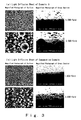
- the mean height H of the protruding parts, the mean diameter D of the protruding parts, the mean occupancy rate of the protruding parts and the surface roughness (Ra) in these light diffusion sheets were determined. Furthermore, these light diffusion sheets were integrated in the edge light type and immediate beneath type backlight units in effect, respectively, and relative values of the face luminance were measured. Moreover, scratching preventive property of the front face of these light diffusion sheets was evaluated. The results are shown in Table 1 below.
- the scratching preventive property was evaluated by visual observation in the test carried out according to JIS-L-0849 "Test methods for colour fastness to rubbing" based on the following criteria:
- the light diffusion sheets of Examples 1 to 12 exhibited favorable scratching preventive property as compared with the light diffusion sheet of Comparative Example in which only the small monodisperse beads were used, and those light diffusion sheets exhibited nearly equal relative values of the face luminance. Furthermore, upon comparison of the light diffusion sheets of Examples 1 to 12, the light diffusion sheets of Examples 2 to 5 and 8 to 11 in which the weight ratio of the small monodisperse beads to the large beads is 6/4 or greater and 9/1 or less were favorable in terms of both face luminance and scratching preventive property. In particular, the light diffusion sheets of Examples 2, 3, 8 and 9 in which the weight ratio is 8/2 or greater and 9/1 or less exhibited high face luminance and excellent scratching preventive property.
Landscapes
- Physics & Mathematics (AREA)
- General Physics & Mathematics (AREA)
- Optics & Photonics (AREA)
- Nonlinear Science (AREA)
- Mathematical Physics (AREA)
- Crystallography & Structural Chemistry (AREA)
- Chemical & Material Sciences (AREA)
- Optical Elements Other Than Lenses (AREA)
- Laminated Bodies (AREA)
- Planar Illumination Modules (AREA)
- Devices For Indicating Variable Information By Combining Individual Elements (AREA)
- Liquid Crystal (AREA)
- Push-Button Switches (AREA)
- Display Devices Of Pinball Game Machines (AREA)
Priority Applications (1)
| Application Number | Priority Date | Filing Date | Title |
|---|---|---|---|
| PL06021166T PL1775603T3 (pl) | 2005-10-14 | 2006-10-09 | Arkusz rozpraszający światło i stosująca go jednostka podświetlająca |
Applications Claiming Priority (1)
| Application Number | Priority Date | Filing Date | Title |
|---|---|---|---|
| JP2005299757A JP5102951B2 (ja) | 2005-10-14 | 2005-10-14 | 光拡散シート及びこれを用いたバックライトユニット |
Publications (2)
| Publication Number | Publication Date |
|---|---|
| EP1775603A1 EP1775603A1 (en) | 2007-04-18 |
| EP1775603B1 true EP1775603B1 (en) | 2008-12-10 |
Family
ID=36026607
Family Applications (1)
| Application Number | Title | Priority Date | Filing Date |
|---|---|---|---|
| EP06021166A Active EP1775603B1 (en) | 2005-10-14 | 2006-10-09 | Light diffusion sheet and backlight unit using the same |
Country Status (11)
| Country | Link |
|---|---|
| US (1) | US8110276B2 (pl) |
| EP (1) | EP1775603B1 (pl) |
| JP (1) | JP5102951B2 (pl) |
| KR (1) | KR100851338B1 (pl) |
| CN (1) | CN100420963C (pl) |
| AT (1) | ATE417291T1 (pl) |
| DE (1) | DE602006004133D1 (pl) |
| ES (1) | ES2318644T3 (pl) |
| MX (1) | MXPA06011887A (pl) |
| PL (1) | PL1775603T3 (pl) |
| TW (1) | TW200730883A (pl) |
Families Citing this family (32)
| Publication number | Priority date | Publication date | Assignee | Title |
|---|---|---|---|---|
| KR100801024B1 (ko) | 2006-06-05 | 2008-02-04 | 엘지전자 주식회사 | 다층 광학 필름, 이를 구비한 백라이트 유닛 및 액정 표시장치 |
| KR100812593B1 (ko) * | 2007-05-23 | 2008-03-13 | 도레이새한 주식회사 | 엘시디 백라이트 유니트용 광확산 시트 |
| KR20100087122A (ko) * | 2007-09-27 | 2010-08-03 | 키모토 컴파니 리미티드 | 표면 요철 필름 및 광확산성 시트 |
| TWI417609B (zh) * | 2007-11-09 | 2013-12-01 | Eternal Chemical Co Ltd | 光學膜 |
| JP5028251B2 (ja) * | 2007-12-26 | 2012-09-19 | 富士フイルム株式会社 | セルロースエステルフィルム、それを用いた位相差フィルム、偏光板、および液晶表示装置 |
| CN101910879B (zh) * | 2008-01-24 | 2013-10-09 | 木本股份有限公司 | 光扩散性薄片及使用其的背光装置 |
| JP5634022B2 (ja) * | 2008-03-06 | 2014-12-03 | 富士フイルム株式会社 | セルロースエステルフィルム、それを用いた位相差フィルム、偏光板、及び液晶表示装置 |
| JP5214284B2 (ja) * | 2008-03-10 | 2013-06-19 | 株式会社東芝 | 発光装置用光取り出し層、およびそれを用いた有機エレクトロルミネッセンス素子 |
| KR100988621B1 (ko) * | 2008-05-07 | 2010-10-20 | 엘지전자 주식회사 | 광 파이프 및 이를 구비한 조명장치 |
| KR100988623B1 (ko) | 2008-05-08 | 2010-10-20 | 엘지전자 주식회사 | 광 파이프 및 이를 구비한 조명장치 |
| US8075167B2 (en) | 2008-05-20 | 2011-12-13 | Lg Electronics Inc. | Optical film and illuminating device having the same |
| JP2010026231A (ja) * | 2008-07-18 | 2010-02-04 | Jiroo Corporate Plan:Kk | 光学シート及びこれを用いたバックライトユニット |
| KR100916300B1 (ko) * | 2009-01-20 | 2009-09-10 | 주식회사 재현테크 | 도광시트 및 그 설치방법 |
| KR101291901B1 (ko) * | 2009-08-05 | 2013-07-31 | 엘지디스플레이 주식회사 | 액정표시장치 |
| WO2011074648A1 (ja) * | 2009-12-17 | 2011-06-23 | 株式会社 きもと | 光拡散性シート及びこれを用いたバックライト |
| CN101840103B (zh) * | 2010-04-23 | 2011-07-13 | 上海凯鑫森产业投资控股有限公司 | 一种用于背光模块的扩散片 |
| KR101705904B1 (ko) * | 2010-11-02 | 2017-02-23 | 엘지디스플레이 주식회사 | 백라이트 유닛 및 이를 포함하는 액정표시장치 |
| JP6046367B2 (ja) * | 2011-04-12 | 2016-12-14 | 恵和株式会社 | 光学ユニット、バックライトユニット及び液晶表示装置 |
| JP2013037164A (ja) * | 2011-08-08 | 2013-02-21 | Sony Corp | 拡散シート、バックライト、液晶表示装置および拡散シートの製造方法 |
| KR20130047334A (ko) * | 2011-10-31 | 2013-05-08 | 엘지이노텍 주식회사 | 조명 부재 및 이를 포함하는 조명 장치 |
| KR101781206B1 (ko) * | 2011-12-30 | 2017-09-25 | 에스케이씨하이테크앤마케팅(유) | 마이크로 렌즈 광학시트, 및 이를 이용한 백라이트 유닛 및 액정 표시 장치 |
| US20180104368A1 (en) * | 2012-04-16 | 2018-04-19 | Sensor Electronic Technology, Inc. | Ultraviolet-Based Sterilization |
| US9999782B2 (en) * | 2012-04-16 | 2018-06-19 | Sensor Electronic Technology, Inc. | Ultraviolet-based sterilization |
| CN102798908B (zh) * | 2012-07-19 | 2014-09-10 | 京东方科技集团股份有限公司 | 一种扩散板、直下式背光模组及显示装置 |
| JP2014116264A (ja) * | 2012-12-12 | 2014-06-26 | Matsuda Screen Inc | 導光板、照明装置、表示装置及び照明器具 |
| JP2014194880A (ja) * | 2013-03-28 | 2014-10-09 | Matsuda Screen Inc | 導光板、照明装置、表示装置及び導光板製造方法 |
| KR101392186B1 (ko) | 2013-06-17 | 2014-05-08 | (주)코이즈 | 복합필름용 확산 합지시트의 제조방법 및 이에 따라 제조한 복합필름 |
| JP2017511755A (ja) | 2014-01-22 | 2017-04-27 | スリーエム イノベイティブ プロパティズ カンパニー | ガラス用微小光学要素 |
| CN107076885B (zh) * | 2014-10-24 | 2020-07-07 | 三菱瓦斯化学株式会社 | 光扩散膜 |
| KR101710097B1 (ko) | 2015-04-03 | 2017-02-27 | 주식회사 엘엠에스 | 광학시트 및 이를 구비한 백라이트 유닛 |
| CN107907926B (zh) * | 2017-12-28 | 2021-03-02 | 深圳大学 | 一种光扩散板及制备方法 |
| CN110456555B (zh) * | 2019-08-27 | 2022-03-15 | 昆山工研院新型平板显示技术中心有限公司 | 彩色滤光片及其制备方法 |
Family Cites Families (17)
| Publication number | Priority date | Publication date | Assignee | Title |
|---|---|---|---|---|
| JP2539491Y2 (ja) * | 1991-10-09 | 1997-06-25 | 惠和商工株式会社 | 光拡散シート材 |
| JP2665301B2 (ja) * | 1992-09-09 | 1997-10-22 | 惠和商工株式会社 | 光拡散シート材 |
| JPH075305A (ja) | 1993-04-19 | 1995-01-10 | Keiwa Shoko Kk | 光拡散シート材 |
| JP3545447B2 (ja) * | 1994-02-04 | 2004-07-21 | 大日本印刷株式会社 | 光拡散フィルム |
| JPH1164611A (ja) | 1997-08-26 | 1999-03-05 | Nitto Denko Corp | 光拡散フィルム |
| JP3119846B2 (ja) | 1998-09-17 | 2000-12-25 | 恵和株式会社 | 光拡散シート及びこれを用いたバックライトユニット |
| JP4652527B2 (ja) * | 2000-05-16 | 2011-03-16 | 株式会社きもと | 光拡散性シート |
| JP4686016B2 (ja) * | 2000-09-26 | 2011-05-18 | 恵和株式会社 | 光拡散シート及びこれを用いたバックライトユニット |
| JP4970647B2 (ja) | 2000-12-11 | 2012-07-11 | 恵和株式会社 | 光学シート及びこれを用いたバックライトユニット |
| JP2002357703A (ja) | 2001-02-07 | 2002-12-13 | Keiwa Inc | 光学シート及びこれを用いたバックライトユニット |
| JP2003057415A (ja) * | 2001-08-21 | 2003-02-26 | Fuji Photo Film Co Ltd | 光拡散フィルム、その製造方法、偏光板および液晶表示装置 |
| JP3822102B2 (ja) * | 2001-12-27 | 2006-09-13 | 富士写真フイルム株式会社 | 光拡散フイルム、その製造方法、偏光板および液晶表示装置 |
| KR100951285B1 (ko) * | 2002-03-06 | 2010-04-02 | 키모토 컴파니 리미티드 | 광확산 시이트 및 면 광원소자 |
| JP4159024B2 (ja) * | 2002-06-25 | 2008-10-01 | 綜研化学株式会社 | 低屈折率ポリマー球状粒子及びその製造方法、その粒子を用いる光特性フィルム及びそのフィルムを設ける画像表示装置 |
| JP4800549B2 (ja) * | 2002-12-18 | 2011-10-26 | 恵和株式会社 | 光学シート及びこれを用いたバックライトユニット |
| JP2007512573A (ja) * | 2003-11-26 | 2007-05-17 | コーロン インダストリーズ インク | 液晶ディスプレイのバックライトユニット用光拡散フィルム |
| JP2005107553A (ja) * | 2005-01-06 | 2005-04-21 | Minoru Yoshida | 光拡散シート及びこれを用いたバックライトユニット |
-
2005
- 2005-10-14 JP JP2005299757A patent/JP5102951B2/ja active Active
-
2006
- 2006-10-09 ES ES06021166T patent/ES2318644T3/es active Active
- 2006-10-09 AT AT06021166T patent/ATE417291T1/de not_active IP Right Cessation
- 2006-10-09 DE DE602006004133T patent/DE602006004133D1/de active Active
- 2006-10-09 PL PL06021166T patent/PL1775603T3/pl unknown
- 2006-10-09 EP EP06021166A patent/EP1775603B1/en active Active
- 2006-10-11 US US11/546,139 patent/US8110276B2/en not_active Expired - Fee Related
- 2006-10-11 TW TW095137316A patent/TW200730883A/zh unknown
- 2006-10-12 KR KR1020060099229A patent/KR100851338B1/ko active IP Right Grant
- 2006-10-13 MX MXPA06011887A patent/MXPA06011887A/es active IP Right Grant
- 2006-10-13 CN CNB2006101723732A patent/CN100420963C/zh active Active
Also Published As
| Publication number | Publication date |
|---|---|
| ES2318644T3 (es) | 2009-05-01 |
| TW200730883A (en) | 2007-08-16 |
| US20070087167A1 (en) | 2007-04-19 |
| ATE417291T1 (de) | 2008-12-15 |
| CN100420963C (zh) | 2008-09-24 |
| PL1775603T3 (pl) | 2009-06-30 |
| MXPA06011887A (es) | 2007-11-22 |
| JP5102951B2 (ja) | 2012-12-19 |
| DE602006004133D1 (de) | 2009-01-22 |
| CN1971316A (zh) | 2007-05-30 |
| JP2006048084A (ja) | 2006-02-16 |
| TWI314999B (pl) | 2009-09-21 |
| US8110276B2 (en) | 2012-02-07 |
| KR100851338B1 (ko) | 2008-08-08 |
| EP1775603A1 (en) | 2007-04-18 |
| KR20070041348A (ko) | 2007-04-18 |
Similar Documents
| Publication | Publication Date | Title |
|---|---|---|
| EP1775603B1 (en) | Light diffusion sheet and backlight unit using the same | |
| US9017793B2 (en) | Light diffusion sheet and backlight unit using the same | |
| US6906761B2 (en) | Reflection sheet and backlight unit using the same | |
| US7072115B2 (en) | Light diffusion sheet and backlight unit using the same | |
| JP2005107553A (ja) | 光拡散シート及びこれを用いたバックライトユニット | |
| KR101079123B1 (ko) | 광학시트 및 이것을 사용한 백라이트 유닛 | |
| JP4271462B2 (ja) | 光拡散シート及びこれを用いたバックライトユニット | |
| JP2004319171A (ja) | 光学ユニット及びこれを用いたバックライトユニット | |
| JP4681791B2 (ja) | 反射シート及びこれを用いたバックライトユニット | |
| KR100523407B1 (ko) | 광확산 시트 및 이것을 사용한 백라이트 유닛 | |
| JP4800549B2 (ja) | 光学シート及びこれを用いたバックライトユニット | |
| JP2004004600A (ja) | 光拡散シート及びこれを用いたバックライトユニット | |
| JP2005077448A (ja) | 光拡散シート及びこれを用いたバックライトユニット | |
| JP4227436B2 (ja) | 光拡散シート及びこれを用いたバックライトユニット | |
| JP4451619B2 (ja) | 光拡散シート及びこれを用いたバックライトユニット | |
| JP2004085626A (ja) | 光学シート及びこれを用いたバックライトユニット | |
| JP2004198722A (ja) | 光学シート及びこれを用いたバックライトユニット | |
| JP2004198707A (ja) | 光学シート及びこれを用いたバックライトユニット | |
| JP4374237B2 (ja) | 光拡散シート | |
| JP2004309802A (ja) | 光学ユニット及びこれを用いたバックライトユニット | |
| JP2004198733A (ja) | 光学シート及びこれを用いたバックライトユニット | |
| JP2004311250A (ja) | 光学ユニット及びこれを用いたバックライトユニット |
Legal Events
| Date | Code | Title | Description |
|---|---|---|---|
| PUAI | Public reference made under article 153(3) epc to a published international application that has entered the european phase |
Free format text: ORIGINAL CODE: 0009012 |
|
| 17P | Request for examination filed |
Effective date: 20061009 |
|
| AK | Designated contracting states |
Kind code of ref document: A1 Designated state(s): AT BE BG CH CY CZ DE DK EE ES FI FR GB GR HU IE IS IT LI LT LU LV MC NL PL PT RO SE SI SK TR |
|
| AX | Request for extension of the european patent |
Extension state: AL BA HR MK YU |
|
| 17Q | First examination report despatched |
Effective date: 20071004 |
|
| AKX | Designation fees paid |
Designated state(s): AT BE BG CH CY CZ DE DK EE ES FI FR GB GR HU IE IS IT LI LT LU LV MC NL PL PT RO SE SI SK TR |
|
| GRAP | Despatch of communication of intention to grant a patent |
Free format text: ORIGINAL CODE: EPIDOSNIGR1 |
|
| GRAS | Grant fee paid |
Free format text: ORIGINAL CODE: EPIDOSNIGR3 |
|
| GRAA | (expected) grant |
Free format text: ORIGINAL CODE: 0009210 |
|
| AK | Designated contracting states |
Kind code of ref document: B1 Designated state(s): AT BE BG CH CY CZ DE DK EE ES FI FR GB GR HU IE IS IT LI LT LU LV MC NL PL PT RO SE SI SK TR |
|
| REG | Reference to a national code |
Ref country code: GB Ref legal event code: FG4D |
|
| REG | Reference to a national code |
Ref country code: CH Ref legal event code: EP |
|
| REG | Reference to a national code |
Ref country code: IE Ref legal event code: FG4D |
|
| REF | Corresponds to: |
Ref document number: 602006004133 Country of ref document: DE Date of ref document: 20090122 Kind code of ref document: P |
|
| PG25 | Lapsed in a contracting state [announced via postgrant information from national office to epo] |
Ref country code: LT Free format text: LAPSE BECAUSE OF FAILURE TO SUBMIT A TRANSLATION OF THE DESCRIPTION OR TO PAY THE FEE WITHIN THE PRESCRIBED TIME-LIMIT Effective date: 20081210 |
|
| REG | Reference to a national code |
Ref country code: ES Ref legal event code: FG2A Ref document number: 2318644 Country of ref document: ES Kind code of ref document: T3 |
|
| PG25 | Lapsed in a contracting state [announced via postgrant information from national office to epo] |
Ref country code: SI Free format text: LAPSE BECAUSE OF FAILURE TO SUBMIT A TRANSLATION OF THE DESCRIPTION OR TO PAY THE FEE WITHIN THE PRESCRIBED TIME-LIMIT Effective date: 20081210 Ref country code: LV Free format text: LAPSE BECAUSE OF FAILURE TO SUBMIT A TRANSLATION OF THE DESCRIPTION OR TO PAY THE FEE WITHIN THE PRESCRIBED TIME-LIMIT Effective date: 20081210 Ref country code: NL Free format text: LAPSE BECAUSE OF FAILURE TO SUBMIT A TRANSLATION OF THE DESCRIPTION OR TO PAY THE FEE WITHIN THE PRESCRIBED TIME-LIMIT Effective date: 20081210 Ref country code: FI Free format text: LAPSE BECAUSE OF FAILURE TO SUBMIT A TRANSLATION OF THE DESCRIPTION OR TO PAY THE FEE WITHIN THE PRESCRIBED TIME-LIMIT Effective date: 20081210 |
|
| NLV1 | Nl: lapsed or annulled due to failure to fulfill the requirements of art. 29p and 29m of the patents act | ||
| REG | Reference to a national code |
Ref country code: PL Ref legal event code: T3 |
|
| PG25 | Lapsed in a contracting state [announced via postgrant information from national office to epo] |
Ref country code: BG Free format text: LAPSE BECAUSE OF FAILURE TO SUBMIT A TRANSLATION OF THE DESCRIPTION OR TO PAY THE FEE WITHIN THE PRESCRIBED TIME-LIMIT Effective date: 20090310 Ref country code: RO Free format text: LAPSE BECAUSE OF FAILURE TO SUBMIT A TRANSLATION OF THE DESCRIPTION OR TO PAY THE FEE WITHIN THE PRESCRIBED TIME-LIMIT Effective date: 20081210 Ref country code: BE Free format text: LAPSE BECAUSE OF FAILURE TO SUBMIT A TRANSLATION OF THE DESCRIPTION OR TO PAY THE FEE WITHIN THE PRESCRIBED TIME-LIMIT Effective date: 20081210 Ref country code: EE Free format text: LAPSE BECAUSE OF FAILURE TO SUBMIT A TRANSLATION OF THE DESCRIPTION OR TO PAY THE FEE WITHIN THE PRESCRIBED TIME-LIMIT Effective date: 20081210 |
|
| PG25 | Lapsed in a contracting state [announced via postgrant information from national office to epo] |
Ref country code: IS Free format text: LAPSE BECAUSE OF FAILURE TO SUBMIT A TRANSLATION OF THE DESCRIPTION OR TO PAY THE FEE WITHIN THE PRESCRIBED TIME-LIMIT Effective date: 20090410 Ref country code: SE Free format text: LAPSE BECAUSE OF FAILURE TO SUBMIT A TRANSLATION OF THE DESCRIPTION OR TO PAY THE FEE WITHIN THE PRESCRIBED TIME-LIMIT Effective date: 20090310 Ref country code: PT Free format text: LAPSE BECAUSE OF FAILURE TO SUBMIT A TRANSLATION OF THE DESCRIPTION OR TO PAY THE FEE WITHIN THE PRESCRIBED TIME-LIMIT Effective date: 20090511 Ref country code: AT Free format text: LAPSE BECAUSE OF FAILURE TO SUBMIT A TRANSLATION OF THE DESCRIPTION OR TO PAY THE FEE WITHIN THE PRESCRIBED TIME-LIMIT Effective date: 20081210 |
|
| PLBE | No opposition filed within time limit |
Free format text: ORIGINAL CODE: 0009261 |
|
| STAA | Information on the status of an ep patent application or granted ep patent |
Free format text: STATUS: NO OPPOSITION FILED WITHIN TIME LIMIT |
|
| PG25 | Lapsed in a contracting state [announced via postgrant information from national office to epo] |
Ref country code: DK Free format text: LAPSE BECAUSE OF FAILURE TO SUBMIT A TRANSLATION OF THE DESCRIPTION OR TO PAY THE FEE WITHIN THE PRESCRIBED TIME-LIMIT Effective date: 20081210 |
|
| 26N | No opposition filed |
Effective date: 20090911 |
|
| PGFP | Annual fee paid to national office [announced via postgrant information from national office to epo] |
Ref country code: FR Payment date: 20091110 Year of fee payment: 4 |
|
| PG25 | Lapsed in a contracting state [announced via postgrant information from national office to epo] |
Ref country code: MC Free format text: LAPSE BECAUSE OF NON-PAYMENT OF DUE FEES Effective date: 20091031 |
|
| REG | Reference to a national code |
Ref country code: IE Ref legal event code: MM4A |
|
| PG25 | Lapsed in a contracting state [announced via postgrant information from national office to epo] |
Ref country code: IE Free format text: LAPSE BECAUSE OF NON-PAYMENT OF DUE FEES Effective date: 20091009 Ref country code: GR Free format text: LAPSE BECAUSE OF FAILURE TO SUBMIT A TRANSLATION OF THE DESCRIPTION OR TO PAY THE FEE WITHIN THE PRESCRIBED TIME-LIMIT Effective date: 20090311 |
|
| PG25 | Lapsed in a contracting state [announced via postgrant information from national office to epo] |
Ref country code: IT Free format text: LAPSE BECAUSE OF FAILURE TO SUBMIT A TRANSLATION OF THE DESCRIPTION OR TO PAY THE FEE WITHIN THE PRESCRIBED TIME-LIMIT Effective date: 20081210 |
|
| PG25 | Lapsed in a contracting state [announced via postgrant information from national office to epo] |
Ref country code: LU Free format text: LAPSE BECAUSE OF NON-PAYMENT OF DUE FEES Effective date: 20091009 |
|
| REG | Reference to a national code |
Ref country code: CH Ref legal event code: PL |
|
| PG25 | Lapsed in a contracting state [announced via postgrant information from national office to epo] |
Ref country code: HU Free format text: LAPSE BECAUSE OF FAILURE TO SUBMIT A TRANSLATION OF THE DESCRIPTION OR TO PAY THE FEE WITHIN THE PRESCRIBED TIME-LIMIT Effective date: 20090611 |
|
| PG25 | Lapsed in a contracting state [announced via postgrant information from national office to epo] |
Ref country code: CH Free format text: LAPSE BECAUSE OF NON-PAYMENT OF DUE FEES Effective date: 20101031 Ref country code: LI Free format text: LAPSE BECAUSE OF NON-PAYMENT OF DUE FEES Effective date: 20101031 Ref country code: FR Free format text: LAPSE BECAUSE OF NON-PAYMENT OF DUE FEES Effective date: 20101102 |
|
| REG | Reference to a national code |
Ref country code: FR Ref legal event code: ST Effective date: 20110630 |
|
| PG25 | Lapsed in a contracting state [announced via postgrant information from national office to epo] |
Ref country code: CY Free format text: LAPSE BECAUSE OF FAILURE TO SUBMIT A TRANSLATION OF THE DESCRIPTION OR TO PAY THE FEE WITHIN THE PRESCRIBED TIME-LIMIT Effective date: 20081210 |
|
| PGFP | Annual fee paid to national office [announced via postgrant information from national office to epo] |
Ref country code: TR Payment date: 20090930 Year of fee payment: 4 |
|
| REG | Reference to a national code |
Ref country code: DE Ref legal event code: R082 Ref document number: 602006004133 Country of ref document: DE Representative=s name: PATENTANWAELTE MAXTON LANGMAACK & PARTNER, DE |
|
| REG | Reference to a national code |
Ref country code: ES Ref legal event code: PC2A Owner name: KEIWA INC. Effective date: 20120710 |
|
| REG | Reference to a national code |
Ref country code: DE Ref legal event code: R082 Ref document number: 602006004133 Country of ref document: DE Representative=s name: PATENTANWAELTE MAXTON LANGMAACK & PARTNER, DE Effective date: 20120710 Ref country code: DE Ref legal event code: R082 Ref document number: 602006004133 Country of ref document: DE Representative=s name: VON KREISLER SELTING WERNER - PARTNERSCHAFT VO, DE Effective date: 20120710 Ref country code: DE Ref legal event code: R082 Ref document number: 602006004133 Country of ref document: DE Representative=s name: DOMPATENT VON KREISLER SELTING WERNER - PARTNE, DE Effective date: 20120710 Ref country code: DE Ref legal event code: R081 Ref document number: 602006004133 Country of ref document: DE Owner name: KEIWA INC., JP Free format text: FORMER OWNER: YOSHIDA, MINORU, MOTOSU-SHI, GIFU, JP Effective date: 20120710 |
|
| REG | Reference to a national code |
Ref country code: SK Ref legal event code: PC4A Ref document number: E 4974 Country of ref document: SK Owner name: KEIWA INC., OSAKA-SHI, OSAKA, JP Free format text: FORMER OWNER: YOSHIDA MINORU, MOTOSU-SHI, GIFU, JP Effective date: 20120416 |
|
| REG | Reference to a national code |
Ref country code: GB Ref legal event code: 732E Free format text: REGISTERED BETWEEN 20120920 AND 20120926 |
|
| PG25 | Lapsed in a contracting state [announced via postgrant information from national office to epo] |
Ref country code: TR Free format text: LAPSE BECAUSE OF NON-PAYMENT OF DUE FEES Effective date: 20101009 |
|
| REG | Reference to a national code |
Ref country code: DE Ref legal event code: R082 Ref document number: 602006004133 Country of ref document: DE Representative=s name: VON KREISLER SELTING WERNER - PARTNERSCHAFT VO, DE Ref country code: DE Ref legal event code: R082 Ref document number: 602006004133 Country of ref document: DE Representative=s name: DOMPATENT VON KREISLER SELTING WERNER - PARTNE, DE |
|
| PGFP | Annual fee paid to national office [announced via postgrant information from national office to epo] |
Ref country code: CZ Payment date: 20170927 Year of fee payment: 12 |
|
| PGFP | Annual fee paid to national office [announced via postgrant information from national office to epo] |
Ref country code: PL Payment date: 20170927 Year of fee payment: 12 |
|
| PGFP | Annual fee paid to national office [announced via postgrant information from national office to epo] |
Ref country code: SK Payment date: 20171004 Year of fee payment: 12 |
|
| PGFP | Annual fee paid to national office [announced via postgrant information from national office to epo] |
Ref country code: ES Payment date: 20171103 Year of fee payment: 12 |
|
| REG | Reference to a national code |
Ref country code: SK Ref legal event code: MM4A Ref document number: E 4974 Country of ref document: SK Effective date: 20181009 |
|
| PG25 | Lapsed in a contracting state [announced via postgrant information from national office to epo] |
Ref country code: CZ Free format text: LAPSE BECAUSE OF NON-PAYMENT OF DUE FEES Effective date: 20181009 |
|
| PG25 | Lapsed in a contracting state [announced via postgrant information from national office to epo] |
Ref country code: SK Free format text: LAPSE BECAUSE OF NON-PAYMENT OF DUE FEES Effective date: 20181009 |
|
| REG | Reference to a national code |
Ref country code: ES Ref legal event code: FD2A Effective date: 20191202 |
|
| PG25 | Lapsed in a contracting state [announced via postgrant information from national office to epo] |
Ref country code: ES Free format text: LAPSE BECAUSE OF NON-PAYMENT OF DUE FEES Effective date: 20181010 Ref country code: PL Free format text: LAPSE BECAUSE OF NON-PAYMENT OF DUE FEES Effective date: 20181009 |
|
| PGFP | Annual fee paid to national office [announced via postgrant information from national office to epo] |
Ref country code: GB Payment date: 20201022 Year of fee payment: 15 |
|
| GBPC | Gb: european patent ceased through non-payment of renewal fee |
Effective date: 20211009 |
|
| PG25 | Lapsed in a contracting state [announced via postgrant information from national office to epo] |
Ref country code: GB Free format text: LAPSE BECAUSE OF NON-PAYMENT OF DUE FEES Effective date: 20211009 |
|
| PGFP | Annual fee paid to national office [announced via postgrant information from national office to epo] |
Ref country code: DE Payment date: 20221027 Year of fee payment: 17 |