EP1775356A2 - Kristallziehungsvorrichtung und Verfahren zur Herstellung von Gruppe-III-Nitrid Kristallen - Google Patents
Kristallziehungsvorrichtung und Verfahren zur Herstellung von Gruppe-III-Nitrid Kristallen Download PDFInfo
- Publication number
- EP1775356A2 EP1775356A2 EP20060122260 EP06122260A EP1775356A2 EP 1775356 A2 EP1775356 A2 EP 1775356A2 EP 20060122260 EP20060122260 EP 20060122260 EP 06122260 A EP06122260 A EP 06122260A EP 1775356 A2 EP1775356 A2 EP 1775356A2
- Authority
- EP
- European Patent Office
- Prior art keywords
- reaction vessel
- crystal growth
- metal
- melt
- temperature
- Prior art date
- Legal status (The legal status is an assumption and is not a legal conclusion. Google has not performed a legal analysis and makes no representation as to the accuracy of the status listed.)
- Withdrawn
Links
- AVVIEIXFZWSEOI-UHFFFAOYSA-N CCC(C1)C1N(C)C(C=C)=C Chemical compound CCC(C1)C1N(C)C(C=C)=C AVVIEIXFZWSEOI-UHFFFAOYSA-N 0.000 description 1
Images


Classifications
-
- C—CHEMISTRY; METALLURGY
- C30—CRYSTAL GROWTH
- C30B—SINGLE-CRYSTAL GROWTH; UNIDIRECTIONAL SOLIDIFICATION OF EUTECTIC MATERIAL OR UNIDIRECTIONAL DEMIXING OF EUTECTOID MATERIAL; REFINING BY ZONE-MELTING OF MATERIAL; PRODUCTION OF A HOMOGENEOUS POLYCRYSTALLINE MATERIAL WITH DEFINED STRUCTURE; SINGLE CRYSTALS OR HOMOGENEOUS POLYCRYSTALLINE MATERIAL WITH DEFINED STRUCTURE; AFTER-TREATMENT OF SINGLE CRYSTALS OR A HOMOGENEOUS POLYCRYSTALLINE MATERIAL WITH DEFINED STRUCTURE; APPARATUS THEREFOR
- C30B9/00—Single-crystal growth from melt solutions using molten solvents
- C30B9/04—Single-crystal growth from melt solutions using molten solvents by cooling of the solution
- C30B9/08—Single-crystal growth from melt solutions using molten solvents by cooling of the solution using other solvents
- C30B9/12—Salt solvents, e.g. flux growth
-
- C—CHEMISTRY; METALLURGY
- C30—CRYSTAL GROWTH
- C30B—SINGLE-CRYSTAL GROWTH; UNIDIRECTIONAL SOLIDIFICATION OF EUTECTIC MATERIAL OR UNIDIRECTIONAL DEMIXING OF EUTECTOID MATERIAL; REFINING BY ZONE-MELTING OF MATERIAL; PRODUCTION OF A HOMOGENEOUS POLYCRYSTALLINE MATERIAL WITH DEFINED STRUCTURE; SINGLE CRYSTALS OR HOMOGENEOUS POLYCRYSTALLINE MATERIAL WITH DEFINED STRUCTURE; AFTER-TREATMENT OF SINGLE CRYSTALS OR A HOMOGENEOUS POLYCRYSTALLINE MATERIAL WITH DEFINED STRUCTURE; APPARATUS THEREFOR
- C30B9/00—Single-crystal growth from melt solutions using molten solvents
- C30B9/04—Single-crystal growth from melt solutions using molten solvents by cooling of the solution
- C30B9/08—Single-crystal growth from melt solutions using molten solvents by cooling of the solution using other solvents
- C30B9/10—Metal solvents
-
- C—CHEMISTRY; METALLURGY
- C30—CRYSTAL GROWTH
- C30B—SINGLE-CRYSTAL GROWTH; UNIDIRECTIONAL SOLIDIFICATION OF EUTECTIC MATERIAL OR UNIDIRECTIONAL DEMIXING OF EUTECTOID MATERIAL; REFINING BY ZONE-MELTING OF MATERIAL; PRODUCTION OF A HOMOGENEOUS POLYCRYSTALLINE MATERIAL WITH DEFINED STRUCTURE; SINGLE CRYSTALS OR HOMOGENEOUS POLYCRYSTALLINE MATERIAL WITH DEFINED STRUCTURE; AFTER-TREATMENT OF SINGLE CRYSTALS OR A HOMOGENEOUS POLYCRYSTALLINE MATERIAL WITH DEFINED STRUCTURE; APPARATUS THEREFOR
- C30B17/00—Single-crystal growth onto a seed which remains in the melt during growth, e.g. Nacken-Kyropoulos method
-
- C—CHEMISTRY; METALLURGY
- C30—CRYSTAL GROWTH
- C30B—SINGLE-CRYSTAL GROWTH; UNIDIRECTIONAL SOLIDIFICATION OF EUTECTIC MATERIAL OR UNIDIRECTIONAL DEMIXING OF EUTECTOID MATERIAL; REFINING BY ZONE-MELTING OF MATERIAL; PRODUCTION OF A HOMOGENEOUS POLYCRYSTALLINE MATERIAL WITH DEFINED STRUCTURE; SINGLE CRYSTALS OR HOMOGENEOUS POLYCRYSTALLINE MATERIAL WITH DEFINED STRUCTURE; AFTER-TREATMENT OF SINGLE CRYSTALS OR A HOMOGENEOUS POLYCRYSTALLINE MATERIAL WITH DEFINED STRUCTURE; APPARATUS THEREFOR
- C30B19/00—Liquid-phase epitaxial-layer growth
- C30B19/02—Liquid-phase epitaxial-layer growth using molten solvents, e.g. flux
-
- C—CHEMISTRY; METALLURGY
- C30—CRYSTAL GROWTH
- C30B—SINGLE-CRYSTAL GROWTH; UNIDIRECTIONAL SOLIDIFICATION OF EUTECTIC MATERIAL OR UNIDIRECTIONAL DEMIXING OF EUTECTOID MATERIAL; REFINING BY ZONE-MELTING OF MATERIAL; PRODUCTION OF A HOMOGENEOUS POLYCRYSTALLINE MATERIAL WITH DEFINED STRUCTURE; SINGLE CRYSTALS OR HOMOGENEOUS POLYCRYSTALLINE MATERIAL WITH DEFINED STRUCTURE; AFTER-TREATMENT OF SINGLE CRYSTALS OR A HOMOGENEOUS POLYCRYSTALLINE MATERIAL WITH DEFINED STRUCTURE; APPARATUS THEREFOR
- C30B19/00—Liquid-phase epitaxial-layer growth
- C30B19/06—Reaction chambers; Boats for supporting the melt; Substrate holders
- C30B19/062—Vertical dipping system
-
- C—CHEMISTRY; METALLURGY
- C30—CRYSTAL GROWTH
- C30B—SINGLE-CRYSTAL GROWTH; UNIDIRECTIONAL SOLIDIFICATION OF EUTECTIC MATERIAL OR UNIDIRECTIONAL DEMIXING OF EUTECTOID MATERIAL; REFINING BY ZONE-MELTING OF MATERIAL; PRODUCTION OF A HOMOGENEOUS POLYCRYSTALLINE MATERIAL WITH DEFINED STRUCTURE; SINGLE CRYSTALS OR HOMOGENEOUS POLYCRYSTALLINE MATERIAL WITH DEFINED STRUCTURE; AFTER-TREATMENT OF SINGLE CRYSTALS OR A HOMOGENEOUS POLYCRYSTALLINE MATERIAL WITH DEFINED STRUCTURE; APPARATUS THEREFOR
- C30B19/00—Liquid-phase epitaxial-layer growth
- C30B19/10—Controlling or regulating
- C30B19/106—Controlling or regulating adding crystallising material or reactants forming it in situ to the liquid
-
- C—CHEMISTRY; METALLURGY
- C30—CRYSTAL GROWTH
- C30B—SINGLE-CRYSTAL GROWTH; UNIDIRECTIONAL SOLIDIFICATION OF EUTECTIC MATERIAL OR UNIDIRECTIONAL DEMIXING OF EUTECTOID MATERIAL; REFINING BY ZONE-MELTING OF MATERIAL; PRODUCTION OF A HOMOGENEOUS POLYCRYSTALLINE MATERIAL WITH DEFINED STRUCTURE; SINGLE CRYSTALS OR HOMOGENEOUS POLYCRYSTALLINE MATERIAL WITH DEFINED STRUCTURE; AFTER-TREATMENT OF SINGLE CRYSTALS OR A HOMOGENEOUS POLYCRYSTALLINE MATERIAL WITH DEFINED STRUCTURE; APPARATUS THEREFOR
- C30B29/00—Single crystals or homogeneous polycrystalline material with defined structure characterised by the material or by their shape
- C30B29/10—Inorganic compounds or compositions
- C30B29/40—AIIIBV compounds wherein A is B, Al, Ga, In or Tl and B is N, P, As, Sb or Bi
- C30B29/403—AIII-nitrides
- C30B29/406—Gallium nitride
-
- C—CHEMISTRY; METALLURGY
- C30—CRYSTAL GROWTH
- C30B—SINGLE-CRYSTAL GROWTH; UNIDIRECTIONAL SOLIDIFICATION OF EUTECTIC MATERIAL OR UNIDIRECTIONAL DEMIXING OF EUTECTOID MATERIAL; REFINING BY ZONE-MELTING OF MATERIAL; PRODUCTION OF A HOMOGENEOUS POLYCRYSTALLINE MATERIAL WITH DEFINED STRUCTURE; SINGLE CRYSTALS OR HOMOGENEOUS POLYCRYSTALLINE MATERIAL WITH DEFINED STRUCTURE; AFTER-TREATMENT OF SINGLE CRYSTALS OR A HOMOGENEOUS POLYCRYSTALLINE MATERIAL WITH DEFINED STRUCTURE; APPARATUS THEREFOR
- C30B9/00—Single-crystal growth from melt solutions using molten solvents
-
- Y—GENERAL TAGGING OF NEW TECHNOLOGICAL DEVELOPMENTS; GENERAL TAGGING OF CROSS-SECTIONAL TECHNOLOGIES SPANNING OVER SEVERAL SECTIONS OF THE IPC; TECHNICAL SUBJECTS COVERED BY FORMER USPC CROSS-REFERENCE ART COLLECTIONS [XRACs] AND DIGESTS
- Y10—TECHNICAL SUBJECTS COVERED BY FORMER USPC
- Y10T—TECHNICAL SUBJECTS COVERED BY FORMER US CLASSIFICATION
- Y10T117/00—Single-crystal, oriented-crystal, and epitaxy growth processes; non-coating apparatus therefor
- Y10T117/10—Apparatus
- Y10T117/1024—Apparatus for crystallization from liquid or supercritical state
- Y10T117/1092—Shape defined by a solid member other than seed or product [e.g., Bridgman-Stockbarger]
Definitions
- the present invention relates to a crystal growth apparatus growing a group III nitride crystal and a method of manufacturing a group III nitride crystal. Particularly, the present invention relates to a manufacturing method of a GaN crystal.
- InGaAlN group III nitride semiconductor
- MOCVD metal-organic chemical vapor deposition process
- MBE molecular beam epitaxy process
- a sapphire substrate is an insulator, it is impossible to provide an electrode directly on the substrate contrary to conventional light-emitting devices constructed on a semiconductor substrate. This means that is necessary to provide an electrode on one of the group III nitride semiconductor layers.
- such a construction necessitates large device area for formation of the electrodes and the cost of the device is increased inevitably.
- there is caused a problem of warp of the substrate because of the use of different materials such as sapphire substrate in combination with the group III nitride semiconductor layers. This problem of warp becomes a serious problem particularly when the device area is increased.
- GaN gallium nitride
- GaN crystal growth process that uses sodium (Na) for the flux (Patent Reference 1).
- sodium (Na) for the flux
- the present invention is made for solving the foregoing problems and has an object of providing a crystal growth apparatus capable of eliminating the diffusion of the alkali metal to the outside positively.
- Another object of the present invention is to provide a manufacturing method for manufacturing a group III nitride crystal while preventing the diffusion of the alkali metal to the outside positively.
- the present invention has been made to solve these problems and has its object of providing a crystal growth apparatus growing a group III nitride crystal while maintaining the temperature generally constant.
- Another object of the present invention is to provide a manufacturing method of a group III nitride crystal while maintaining the temperature generally constant.
- the crystal growth apparatus having an inner reaction vessel holding therein a melt mixture of metal Na and metal Ga and an outer reaction vessel surrounding the inner reaction vessel and causing crystal growth of a GaN crystal by reacting a melt mixture of metal Na and metal Ga with a nitrogen source material including nitrogen, the crystal growth of the GaN crystal is conducted in the state in which the inner reaction vessel and the outer reaction vessel are pressurized to a pressure higher than the atmospheric pressure.
- the state of the inner reaction vessel is changed and it becomes difficult to conduct crystal growth of the group III nitride crystal stably.
- the nitrogen source gas and the metal Na vapor existing in the space inside the inner reaction vessel may cause leakage to the outer reaction vessel, while such leakage invites decrease of pressure inside the inner reaction vessel.
- incorporation of the nitrogen source gas into the melt mixture becomes unstable and it becomes difficult to cause stable crystal growth of the GaN crystal.
- the present invention has been made for solving these problems and has an object of providing a method for manufacturing a GaN crystal stably.
- the crystal growth apparatus having an inner reaction vessel holding therein a melt mixture of an alkali metal and a group III metal and an outer reaction vessel surrounding the inner reaction vessel and causing crystal growth of a GaN crystal by reacting a melt mixture of the alkali metal and the group III metal with a group V source material including nitrogen, the crystal growth of the GaN crystal is conducted in the state in which the inner reaction vessel and the outer reaction vessel are pressurized to a pressure higher than the atmospheric pressure.
- the state of the inner reaction vessel is changed and it becomes difficult to conduct crystal growth of the GaN crystal stably.
- the nitrogen source gas and the alkali metal vapor existing in the space inside the inner reaction vessel may cause leakage to the outer reaction vessel, while such leakage invites decrease of pressure inside the inner reaction vessel.
- incorporation of the nitrogen source gas into the melt mixture becomes unstable and it becomes difficult to cause stable crystal growth of the GaN crystal.
- the pressure inside the outer reaction vessel is higher than the pressure of the inner reaction vessel, there is a possibility that impurities may invade into the inner reaction vessel from the outer reaction vessel, the nitrogen source gas is not incorporated into the melt mixture stably in the inner reaction vessel, and stable crystal growth of a GaN crystal is difficult.
- the present invention has been made for solving these problems and has an object of providing a crystal growth apparatus for growing a group III nitride crystal stably.
- Another object of the present invention is to provide a manufacturing method for manicuring a group III nitride crystal stably.
- the crystal growth is conducted without using a substrate, and associated with this, there occurs extensive nucleation on the bottom surface and sidewall surface of the reaction vessel. Thereby crystal growth takes place from a particular nucleus among the large number of nuclei thus formed. As a result, other nuclei function to retard the crystal growth of the group III nitride crystal growing preferentially from the foregoing particular nucleus, and there is caused the problem that the group III nitride crystal thus obtained has a small crystal size.
- the present invention has been made to solve these problems and has its object of providing a crystal growth apparatus growing a group III nitride crystal of large crystal size.
- Another object of the present invention is to provide a manufacturing method of a group III nitride crystal of large crystal size.
- the crystal growth method for growing a GaN crystal by reacting a melt mixture of an alkali metal and a group III metal with a group V source material including nitrogen growth is made without using a substrate, and associated with this, there occurs extensive nucleation on the bottom surface and side wall surface of the reaction vessel, wherein crystal growth takes place from a particular nucleus among the large number of nuclei thus formed.
- other nuclei function to retard the crystal growth of the group III nitride crystal growing preferentially from the foregoing particular nucleus, and there is caused the problem that the group III nitride crystal thus obtained has a small crystal size.
- the present invention has been made to solve these problems and has its object of providing a crystal growth apparatus growing a group III nitride crystal of large crystal size.
- Another object of the present invention is to provide a manufacturing method of a group III nitride crystal of large crystal size.
- a crystal growth apparatus having a crucible, a reaction vessel, an alkali metal melt, a gas supplying unit and a heating unit.
- the crucible holds a melt mixture containing an alkali metal and a group III metal.
- the reaction vessel surrounds the crucible.
- the alkali metal melt exists between a vessel space exposed to the melt mixture and outside thereof at a temperature equal to or higher than a melting temperature of the alkali metal.
- the gas supplying unit supplies a nitrogen source gas to the vessel space via the alkali metal melt.
- the heating unit heats the crucible and the reaction vessel to a crystal growth temperature.
- M1 stands for the amount of the alkali metal loaded between the vessel space and the outside while M2 stands for the amount of the alkali metal existing in the vessel space in the form of vapor.
- the gas supplying unit comprises a conduit and a stopper/inlet member.
- the conduit is connected to the reaction vessel.
- the stopper/inlet member is provided inside the conduit and suppresses the diffusion of the alkali metal melt to the outside. Further, the stopper/inlet member introduces the nitrogen source gas into the vessel space via the alkali metal melt. Further, there holds a relationship M1-M2>M3, where M3 stands for the amount of the alkali metal adhered to the stopper/inlet member in the form of liquid or solid.
- M1-M2-M4>0 there holds a relationship M1-M2-M4>0, where M1 stands for the amount of the alkali metal loaded between the vessel space and the outside, M2 stands for the amount of the alkali metal existing in the vessel space in the form of vapor, and M4 stands for the amount of the alkali metal adhered to a low temperature region exposed to the vessel space in the form of liquid or solid.
- the gas supplying unit comprises a conduit and a stopper/inlet member.
- the conduit is connected to the reaction vessel.
- the stopper/inlet member is provided inside the conduit and suppresses the diffusion of the alkali metal melt to the outside. Further, the stopper/inlet member introduces the nitrogen source gas into the vessel space via the alkali metal melt. Further, there holds a relationship M1-M2-M4>M3, where M3 stands for the amount of the alkali metal adhered to the stopper/inlet member in the form of liquid or solid.
- the alkali metal melt exists between the crucible and the reaction vessel.
- a location of an interface between the melt mixture and the vessel space coincides generally to a location of an interface between the alkali metal melt and the vessel space.
- the present invention provides a method for manufacturing a group III nitride crystal by using a crystal growth apparatus, the crystal growth apparatus comprising a crucible for holding a melt mixture containing an alkali metal and a group III metal and a reaction vessel surrounding the crucible, the method comprising: a first step of introducing the alkali metal and the group III metal into the reaction vessel in an ambient of inert gas or nitrogen gas; a second step of loading the alkali metal between the vessel space exposed to the melt mixture and an outside thereof with an amount such that the alkali metal can exist between the vessel space and the exterior at a temperature equal to or higher than the melting temperature of the alkali metal; a third step of filling the vessel space with a nitrogen source gas; a fourth step of heating the crucible and the reaction vessel to a crystal growth temperature; a fifth step of holding the crucible and the reaction vessel at the crystal growth temperature for a predetermined duration; and a sixth step of supplying the nitrogen source gas to the vessel space such that an
- the second step is conducted so as to load the alkali metal between the vessel space and the outside with an amount larger than the amount of the alkali metal existing in the vessel space at the temperature equal to or higher than the melting temperature of the alkali metal.
- the crystal growth apparatus further comprises a conduit and a stopper/inlet member.
- the conduit is connected to the reaction vessel.
- the stopper/inlet member is provided inside the conduit and suppresses the diffusion of the alkali metal melt to the outside. Further, the stopper/inlet member introduces the nitrogen source gas into the vessel space via the alkali metal melt. Further, with the second step of the manufacturing method, the alkali metal is loaded between the vessel space and the outside with an amount larger than a sum of the alkali metal adhered to the stopper/inlet member in the form of liquid or solid and the amount of the alkali metal existing in the vessel space in the form of vapor.
- the second step is conducted so as to load the alkali metal between the vessel space and the outside with an amount larger than a sum of the amount of the alkali metal existing in the vessel space at the temperature equal to or higher than the melting temperature of the alkali metal and the amount of the alkali metal adhered to the low temperature region adjacent to the vessel space in the form of liquid or solid.
- the crystal growth apparatus further comprises a conduit and a stopper/inlet member.
- the conduit is connected to the reaction vessel.
- the stopper/inlet member is provided inside the conduit and suppresses the diffusion of the alkali metal melt to the outside. Further, the stopper/inlet member introduces the nitrogen source gas into the vessel space via the alkali metal melt.
- the alkali metal is loaded between the vessel space and the outside with an amount larger than a sum of the alkali metal adhered to the stopper/inlet member in the form of liquid or solid, the amount of the alkali metal existing in the vessel space in the form of vapor, and the amount of the alkali metal adhered to the low temperature region adjacent to the vessel space in the form of liquid or solid.
- the second step is conducted such that the alkali metal is loaded between the crucible and the reaction vessel in an ambient of inert gas or nitrogen gas with an amount such that the alkali metal can exist between the crucible and the reaction vessel at a temperature equal to or higher than the melting temperature of the alkali metal.
- manufacturing of the group III nitride crystal is attained by loading the alkali metal between the vessel space and the outside with an amount such that the alkali metal can exist between the vessel space exposed to the melt mixture and the exterior at the temperature equal to or higher than the melting temperature of the alkali melt.
- the group III nitride crystal is manufactured in the state in which a liquid of the alkali metal exists between the melt mixture and the outside and in the state in which the vapor of the alkali metal evaporated from the melt mixture is confined between the melt mixture and the alkali metal melt.
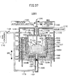
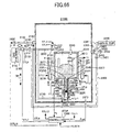
- a crystal growth apparatus having a reaction vessel, a crucible, a gas supplying unit, a heating unit, and a heat blanket unit.
- the crucible is disposed inside the reaction vessel and holds a melt mixture containing an alkali metal and a group III metal.
- the gas supplying unit supplies a nitrogen source gas to a vessel space exposed to the melt mixture inside the crucible.
- the heating unit heats the crucible and the reaction vessel to a crystal growth temperature.
- the heat blanket unit provides heat blanket to the crucible and the reaction vessel.
- the heat blanket unit includes a shielding member surrounding the reaction vessel and interrupting a flow of gas in a direction away from the reaction vessel.
- the shielding member comprises a first shielding member and a second shielding member.
- the first shielding member covers a sidewall of the reaction vessel.
- the second shielding member covers a lid of the reaction vessel disposed at a top part of the crucible and is disposed so as to surround the first shielding member.
- the shielding member comprises first through third shielding members.
- the first shielding member covers a sidewall of the reaction vessel.
- the second shielding member covers a lid of the reaction vessel disposed at a top part of the crucible and is disposed so as to surround the first shielding member.
- the third shielding member surrounds the second shielding member.
- the crystal growth apparatus further comprises a bellows and a support unit.
- the bellows is connected to the lid of the reaction vessel disposed over the crucible.
- the support unit has an end inserted into the vessel space via the bellows and holds a seed crystal thereon.
- the shielding member comprises a first shielding member and a second shielding member.
- the first shielding member covers a sidewall of the reaction vessel.
- the second shielding member covers the lid of the reaction vessel except for the connection part of the lid and the bellows and is disposed so as to surround the first shielding member.
- the shielding member further comprises a third shielding member.
- the third shielding member covers the bellows and the second shielding member.
- the heating unit comprises a heater.
- the heater is disposed so as to face the sidewall of the reaction vessel.
- the heat blanket unit further includes a filling material. The filling material is provided at least between the heater and the first metal member.
- the crystal growth apparatus further comprises an outer reaction vessel.
- the outer reaction vessel accommodates therein the reaction vessel and the heat shielding member and is set to a pressure higher than an atmospheric pressure.
- the heat shielding member is disposed in a space between the reaction vessel and the outer reaction vessel.
- a manufacturing method of a group III nitride crystal by using a crystal growth apparatus including a crucible holding a melt mixture of an alkali metal and a group III metal, and a reaction vessel accommodating therein the crucible, the method comprising a first step of introducing the alkali metal and the group III metal into the reaction vessel in an ambient of inert gas or nitrogen gas; a second step of filling a vessel space exposed to the melt mixture in the crucible with a nitrogen source gas; and crowing a group III nitride crystal while thermally blanketing the crucible and the reaction vessel.
- the group III nitride crystal is grown in the third step while preventing escaping of heat from the crucible and the reaction vessel by way of convection.
- the crystal growth apparatus further comprises first and second heaters and a shielding member.
- the first heater is disposed so as to face the sidewall of the reaction vessel.
- the second heater is disposed so as to face the bottom of the reaction vessel.
- the shielding member is provided at least around the first heater and blocks the flow of gas away from the reaction vessel.
- the third step comprises a first sub-step of heating the crucible and the reaction vessel to the crystal growth temperature by using the first and second heaters, a second sub-step of holding the crucible and the reaction vessel at the crystal growth temperature for a predetermined duration, and a third sub-step of supplying the nitrogen source gas into the reaction vessel such that the pressure inside the reaction vessel is maintained at a predetermined pressure.
- the shielding member includes a first shielding member and a second shielding member.
- the first shielding member is disposed so as to face the first heater.
- the second shielding member covers a lid of the reaction vessel disposed at a top part of the crucible and further the first shielding member.
- the shielding member further comprises a third shielding member.
- the third shielding member surrounds the second shielding member.
- the crystal growth apparatus further comprises a bellows and a support unit.
- the bellows is connected to the lid of the reaction vessel disposed over the crucible.
- the support unit has an end inserted into the vessel space via the bellows and holds a seed crystal thereon.
- the shielding member comprises a first shielding member and a second shielding member.
- the first shielding member is disposed so as to face the first heater.
- the second shielding member covers the lid of the reaction vessel except for the connection part of the lid and the bellows and is disposed so as to surround the first shielding member.
- the manufacturing method further comprises a fourth step for holding the seed crystal at the interface between the vessel space and the melt mixture or inside the melt mixture.
- the crystal growth apparatus further includes a third shielding member such that the third shielding member covers the bellows and the second shielding member.
- the crystal growth apparatus further comprises a filling material.
- the filling material is provided at least between the first heater and the first shielding member.
- the crystal growth apparatus further comprises an outer reaction vessel.
- the outer reaction vessel accommodates therein the reaction vessel and the heat shielding member and is set to a pressure higher than an atmospheric pressure.
- the heat shielding member is disposed in a space between the reaction vessel and the outer reaction vessel.
- the group III nitride crystal is grown in the state in which the crucible and the reaction vessel are thermally blanketed.
- the crucible and the reaction vessel are thermally blanketed by preventing escaping of heat by way of convection, by providing the shielding member.
- a manufacturing method of a GaN crystal by using a crystal growth apparatus comprising: a crucible holding a melt mixture containing metal Na and metal Ga; an internal reaction vessel surrounding the crucible; and an outer reaction vessel surrounding the inner reaction vessel, the method comprising: a first step of loading the metal Na and the metal Ga into the crucible in an ambient of inert gas or nitrogen gas while preventing reaction therebetween; a second step of setting the reaction vessel accommodating therein the crucible in the crystal growth apparatus in a state in which an interior space of the inner reaction vessel is disconnected from outside, the second step further including the step of connecting a gas supply source of the nitrogen gas source with the inner reaction vessel; a third step of purging a part between the gas supply source and the inner reaction vessel in a state in which the inner space of the inner reaction vessel is disconnected from outside; a fourth step of filling a nitrogen source gas in the inner reaction vessel and the outer reaction vessel while maintaining a pressure difference between a first pressure inside the inner reaction vessel and
- the nitrogen source gas is filled into the inner reaction vessel and the outer reaction vessel in the fourth step while maintaining the first pressure and the second pressure generally the same.
- the crystal growth apparatus further comprises: a conduit having an end connected to the inner reaction vessel and another end connected to a gas supply source; a metal Na melt held in the conduit; and a stopper/inlet member disposed in the reaction vessel, the stopper/inlet member holding the metal Na melt at least within the conduit and supplying the nitrogen source gas supplied from the gas supply source to the vessel space exposed to the melt mixture via the metal Na melt.
- the manufacturing method includes a sixth step of loading metal Na into the conduit in an ambient of inert gas or nitrogen gas, wherein the second through fifth steps are conducted after the first and sixth steps.
- the fifth step comprises a first sub-step of heating the crucible and the inner reaction vessel to the crystal growth temperature while maintaining a pressure difference between a third pressure applied to the stopper/inlet member from a side of the inner reaction vessel and a fourth pressure applied to the stopper/inlet member from a side of the gas supply source, to be equal to or lower than a second reference value, the first sub-step further setting a pressure of the vessel space to a crystal growth pressure; and a second sub-step of holding the crystal growth temperature and the crystal growth pressure.
- the fifth step further comprises a third sub-step of replenishing the nitrogen source gas to the vessel space via the stopper/inlet member and the metal Na melt while holding a pressure difference between the third pressure and the fourth pressure to be equal to or smaller than the second reference value, such that the pressure of the vessel space is held generally to the crystal growth pressure.
- the second reference value is one of a withstand pressure of the inner reaction vessel and a withstand pressure of the stopper/inlet member, whichever is the smallest.
- the crystal growth apparatus further comprises: a conduit having an end connected to the inner reaction vessel and another end connected to a gas supply source; a metal Na melt held in the conduit; and a check valve disposed in the conduit, the check valve holding the metal Na melt at least within the conduit and supplying the nitrogen source gas supplied from the gas supply source to the vessel space exposed to the melt mixture via the metal Na melt.
- the manufacturing method includes a sixth step of loading metal Na into the conduit in an ambient of inert gas or nitrogen gas, wherein the second through fifth steps are conducted after the first and sixth steps.
- the fifth step comprises a first sub-step of heating the crucible and the inner reaction vessel to the crystal growth temperature and setting the pressure of the vessel space to the crystal growth pressure and a second sub-step of holding the crystal growth temperature and the crystal growth pressure.
- the fifth step further comprises a third sub-step of supplying the nitrogen source gas to the vessel space via the check valve and the metal Na melt such that the pressure of the reaction vessel is held generally t the crystal growth pressure.
- the fifth step comprises a fourth sub-step of setting the stopper/inlet member or the check valve to a temperature at which a first vapor pressure of the metal Na evaporating from the metal Na melt is generally coincident to a second vapor pressure of the metal Na evaporating from the melt mixture.
- the fifth step further includes a fifth sub-step, after the first and second sub-steps, of causing the seed crystal of GaN with an interface between the melt mixture and the vessel space or dipping the seed crystal of GaN into the melt mixture.
- the fifth step further includes a sixth sub-step of setting a temperature of the seed crystal to be a temperature lower than the temperature of the melt mixture.
- the sixth sub-step is conducted such that a temperature difference between the melt mixture and the seed crystal is increased with progress of crystal growth of the GaN crystal from the seed crystal.
- the method further comprises, after the fifth step, of a seventh step of lowering the temperature of the crucible and the inner reaction vessel from the crystal growth temperature to a predetermined temperature while maintaining a pressure difference between the third pressure and the fourth pressure to be equal to or smaller than the second reference value.
- the manufacturing method further includes an eighth step of holding the temperature of the stopper/inlet member or the check valve generally at the predetermined temperature during the interval in which the temperature of the crucible and the inner reaction vessel is lowered from the crystal growth temperature to the predetermined temperature.
- the crystal growth apparatus further includes a communication valve communicating the vessel space and a space inside the outer reaction vessel.
- the manufacturing method further includes a ninth step of opening the communication valve during the interval of lowering the temperature when the temperature of the crucible and the inner reaction valve has reached a predetermined temperature.
- the tenth step further comprises the step of cooling the crucible and the inner reaction vessel naturally.
- the tenth step further includes the step of cooling the stopper/inlet member or the check valve naturally.
- growth of the GaN crystal is achieved by filling a nitrogen gas in the inner reaction vessel and the outer reaction vessel while maintaining a pressure difference between the first pressure of the inner reaction vessel and the second pressure of the outer reaction vessel to be equal to or smaller than the first reaction vessel and while maintaining the mixing ratio of the metal Na and the metal Ga in the melt mixture generally constant.
- running out of the nitrogen gas and metal Na vapor from the inner reaction vessel to the outer reaction vessel and inflow of gas from the outer reaction vessel to the inner reaction vessel is suppressed, and growth of the GaN crystal is achieved while maintaining the ambient of the vessel space exposed to the melt mixture generally constant.
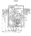
- a crystal growth apparatus having an inner reaction vessel, an outer reaction vessel, a gas supplying unit, a heating unit, and a pressure holding unit.
- the inner reaction vessel holds a melt mixture containing an alkali metal and a group III metal.
- the outer reaction vessel surrounds the inner reaction vessel.
- the gas supplying unit supplies a nitrogen source gas to a first vessel space exposed to the melt mixture inside the inner reaction vessel.
- the heating unit heats the inner reaction vessel to a crystal growth temperature.
- the pressure holding unit holds the pressure difference between a first pressure inside the inner reaction vessel and a second pressure of the outer reaction vessel to a suitable pressure difference at the time when the inner reaction vessel has been heated to the crystal growth temperature.
- the suitable pressure difference is a pressure difference that causes substantial disconnection of the first vessel space from the second vessel space formed between the inner reaction vessel and the outer reaction vessel when the inner reaction vessel has been heated to the crystal growth temperature.
- the pressure holding unit holds the pressure difference to a value smaller than a predetermined value at which it is judged that the crystal growth apparatus is in an anomalous state.
- the pressure holding unit comprises first and second pressure sensors and a pressure regulator.
- the first pressure sensor detects the first pressure.
- the second pressure sensor detects the second pressure.
- the pressure regulator controls the second pressure based on the first and second pressures detected respectively by the first and second pressure sensors such that the pressure difference takes a value smaller than the predetermined value.
- the pressure regulator increases the second pressure in the event the pressure difference is equal to or larger than the predetermined value and when the first pressure is higher than the second pressure, such that the pressure difference takes a value smaller than the predetermined value. Further, the pressure regulator lowers the second pressure in the event the pressure difference is equal to or larger than the predetermined value and when the first pressure is lower than the second pressure, such that the pressure difference takes a value smaller than the predetermined value.
- the pressure regulator maintains the detected first pressure.
- the crystal growth apparatus further comprises a crucible and a melt support member.
- the crucible is disposed inside the inner reaction vessel and holds the melt mixture.
- the melt mixture support member holds a metal melt between a first vessel space and an outer space.
- the first pressure sensor detects a hydrostatic pressure of the metal melt and detects the first pressure, which is the pressure inside the first vessel space, based on the detected hydrostatic pressure.
- the crystal growth apparatus further comprises a conduit connected to the inner reaction vessel.
- the melt support member is disposed in a temperature region where there is caused no substantial evaporation in the metal melt inside the conduit, wherein the melt support member holds the metal melt between the crucible and the inner reaction vessel and in the conduit by the surface tension of the metal melt.
- the first pressure detector detects a hydrostatic pressure of the metal melt held in the vicinity of the melt support member.
- the melt support member comprises a porous member.
- the metal melt is different from the melt mixture.
- the metal melt is an alkali metal melt, which is a melt of an alkali metal.
- a method for manufacturing a group III nitride crystal by using a crystal growth apparatus comprising an inner reaction vessel holding a melt mixture containing an alkali metal and a group III metal and an outer reaction vessel surrounding the inner reaction vessel, the method comprising: a first step of loading the alkali metal and the group III metal to the inner reaction vessel in an ambient of inert gas or nitrogen gas; a second step of filling a nitrogen source gas in a first vessel space exposed to the melt mixture in the inner reaction vessel; a third step of heating the inner reaction vessel to a crystal growth temperature; a fourth step of holding the inner reaction vessel at the crystal growth temperature for a predetermined duration; and a fifth step of maintaining a pressure difference between a first pressure inside the inner reaction vessel and a second pressure inside the outer reaction vessel for the case when the inner reaction vessel is heated to the crystal growth temperature, to be a suitable pressure difference.
- the suitable pressure difference is a pressure difference that causes substantial disconnection of the first
- the fifth step holds the pressure difference to a value smaller than a predetermined value at which it is judged that the crystal growth apparatus is in an anomalous state.
- the fifth step comprises a first sub-step of detecting the first and second pressures and a second sub-step of adjusting the second pressure based on the detected first and second pressures such that the pressure difference takes a value smaller than the predetermined value.
- the second sub-step comprises: a step of calculating the pressure difference from the detected first and second pressures; a step of increasing the second pressure when the calculated pressure difference is larger than the predetermined value and when the first pressure is higher than the second pressure, such that the pressure difference becomes smaller than the predetermined value; and a step of decreasing the second pressure when the calculated pressure difference is larger than the predetermined value and when the first pressure is lower than the second pressure, such that the pressure difference becomes smaller than the predetermined value.
- the fifth step further includes a third sub-step of holding the detected first pressure.
- the crystal growth apparatus is disposed inside the inner reaction vessel and includes a crucible holding the melt mixture and a melt support member holding a metal melt between the first vessel space and the outer space.
- the first sub-step detects a hydrostatic pressure of the metal melt and detects the first pressure, which is the pressure inside the first vessel space, based on the detected hydrostatic pressure.
- the crystal growth apparatus further comprises a conduit connected to the inner reaction vessel.
- the melt support member is disposed in a temperature region where there is caused no substantial evaporation in the metal melt inside the conduit, wherein the melt support member holds the metal melt between the crucible and the inner reaction vessel and in the conduit by the surface tension of the metal melt.
- the first SUB-STEP detects a hydrostatic pressure of the metal melt held in the vicinity of the melt support member.
- the melt support member comprises a porous member.
- the metal melt is different from the melt mixture.
- the metal melt is an alkali metal melt, which is a melt of an alkali metal.
- the group III nitride crystal is grown in the inner reaction vessel in a state in which the pressure difference between the first pressure inside the inner reaction vessel and the second pressure inside the outer reaction vessel is maintained to a suitable pressure difference in which the first vessel space exposed to the melt mixture in the inner reaction vessel is disconnected substantially from the second vessel space between the inner reaction vessel and the outer reaction vessel.
- the crystal growth of the group III nitride crystal is carried out while suppressing leakage of the nitrogen source gas and the melt mixture inside the inner reaction vessel from the inner reaction vessel to the outside and further suppressing invasion of impurities from the second vessel space into the first vessel space.
- the growth of the group III nitride crystal is achieved while maintaining the state of the nitrogen source gas and the melt mixture in the inner reaction vessel.
- manufacturing of a group III nitride crystal is achieved stably. Further, according to the present invention, it becomes possible to detect the pressure in the region of low temperature by detecting the pressure of the inner reaction vessel in the form of the metal hydrostatic pressure, and as a result, the accuracy of pressure detection is increased. Thereby, the degree of disconnection is improved.
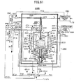
- a crystal growth apparatus having a reaction vessel, a gas supplying unit, a heating unit, a support unit, an etching unit, and a moving unit.
- the reaction unit holds a melt mixture containing an alkali metal and a group III metal.
- the gas supplying unit supplies a nitrogen source gas to a vessel space exposed to the melt mixture inside the reaction vessel.
- the heating unit heats the reaction vessel to a crystal growth temperature.
- the support unit supports a seed crystal of a group III nitride crystal.
- the etching unit etches the seed crystal.
- the moving unit moves the support unit such that the etched seed crystal is supported at the interface between the vessel space and the melt mixture or inside the melt mixture.
- the etching unit etches the seed crystal by the melt mixture.
- the etching unit conducts the etching of the seed crystal while holding the pressure of the nitrogen source gas in the vessel space and the temperature of the melt mixture to a value such thjat there is caused dissolution of the seed crystal.
- the etching unit etches the seed crystal by a metal melt different from the melt mixture.
- the melt mixture comprises an alkali metal melt.
- the etching unit includes an outer reaction vessel connected to the vessel space and holds the metal melt. Further, the heating unit heats the reaction vessel and the outer reaction vessel to a crystal growth temperature.
- the outer reaction vessel surrounds the reaction vessel and holds the metal melt between the outer reaction vessel and the reaction vessel.
- the etching unit comprises an outer vessel connected to the vessel space and holds the metal melt and another heating unit heating the outer vessel to a temperature higher than the crystal growth temperature.
- a method of manufacturing a group III nitride crystal by using a crystal growth apparatus the crystal growth apparatus having a reaction vessel holding a melt mixture containing an alkali metal and a group III metal
- the method comprising: a first step of loading the alkali metal and the group III metal to the reaction vessel in an ambient of inert gas or nitrogen gas; a second step of setting a seed crystal of a group III nitride crystal above the alkali metal and the group III metal in the reaction vessel; filling a vessel space inside the reaction vessel with a nitrogen source gas; a fourth step of heating the reaction vessel to a crystal growth temperature; a fifth step of etching the seed crystal; a sixth step of supporting the etched seed crystal at an interface between the vessel space and the melt mixture or inside the melt mixture; a seventh step of holding the reaction vessel at a crystal growth temperature for a predetermined duration; and an eighth step of supplying a nitrogen source gas to the reaction vessel such that a pressure inside the reaction vessel is maintained at
- the fifth step carries out the etching of the seed crystal by dipping the seed crystal in the melt mixture.
- the fifth step conducts the etching of the seed crystal while holding the pressure of the nitrogen source gas in the vessel space and the temperature of the melt mixture to a value such that there is caused dissolution of the seed crystal.
- the fifth step etches the seed crystal by a metal melt different from the melt mixture.
- the fifth step etches the seed crystal by an alkali metal melt.
- the crystal growth apparatus includes an outer reaction vessel connected to the vessel space and holds the metal melt.
- the fifth step includes: a first sub-step of holding the seed crystal in the vessel space; and a second sub-step of heating the outer vessel such that a vapor pressure of the metal melt is higher than a vapor pressure of the alkali metal in the vessel space.
- the second sub-step heats the outer vessel to a temperature higher than the crystal growth temperature.
- the group III nitride crystal is grown preferentially from a seed crystal of the group III nitride crystal by etching the seed crystal and by causing the etched seed crystal to make a contact with the melt mixture. With such a procedure, impurities adhered to the surface of the seed crystal are removed, and crystal growth of the group III nitride crystal occurring from the sites other than the seed crystal is suppressed
- the seed crystal is etched by dipping into the melt mixture.
- the seed crystal is etching by the metal vapor evaporated from the melt mixture or the metal vapor evaporated from the metal melt different from the melt mixture in the state that the seed crystal is held in the space inside the reaction vessel.
- the present invention it becomes possible to carry out crystal growth of the group III nitride crystal while suppressing contamination of the metal mixture by the impurities adhered to the surface of the seed crystal. As a result, a high-quality group III nitride crystal is manufactured.
- the seed crystal is etched by the alkali metal vapor evaporated from the alkali metal melt held in an outer vessel different from the reaction vessel and has caused diffusion from the outer vessel into the reaction vessel in the state the seed crystal is held in the space inside the reaction vessel.
- a crystal growth apparatus having a reaction vessel, a gas supplying unit, a heating unit, and support unit.
- the reaction unit holds a melt mixture containing an alkali metal and a group III metal.
- the gas supplying unit supplies a nitrogen source gas to a vessel space exposed to the melt mixture inside the reaction vessel.
- the heating unit heats the reaction vessel to a crystal growth temperature.
- the support unit supports a seed crystal of a group III nitride crystal inside the melt mixture.
- the crystal growth apparatus further comprises a temperature setting unit and a temperature control unit.
- the temperature setting unit set the temperature of the seed crystal to a predetermined temperature.
- the temperature control unit controls the heating unit and the temperature setting unit such that the temperate of the seed crystal is lower than the temperature of the melt mixture.
- a crystal growth apparatus having a reaction vessel, a gas supplying unit, a heating unit, a support unit, a temperature setting unit, and a temperature control unit.
- the reaction unit holds a melt mixture containing an alkali metal and a group III metal.
- the gas supplying unit supplies a nitrogen source gas to a vessel space exposed to the melt mixture inside the reaction vessel.
- the heating unit heats the reaction vessel to a crystal growth temperature.
- the support unit supports a seed crystal of a group III nitride crystal at an interface between the vessel space and the melt mixture.
- the temperature setting unit set the temperature of the seed crystal to a predetermined temperature.
- the temperature control unit controls the heating unit and the temperature setting unit such that the temperate of the seed crystal is lower than the temperature of the melt mixture.
- the crystal growth apparatus further comprises a concentration detection unit and a moving unit.
- the concentration detection unit detects a nitrogen concentration or a concentration of the group III nitride in the melt mixture.
- the moving unit moves the support unit, when the detected nitrogen concentration or the concentration of the group III nitride has reached a supersaturation state, such that the seed crystal makes a contact with the melt mixture or the seed crystal is dipped into the melt mixture.
- the moving unit moves the support unit such that the seed crystal is held in the vessel space until the nitrogen concentration or the concentration of the group III nitride in the melt mixture has become the supersaturation state and moves the support unit, when the detected nitrogen concentration or the group III nitride concentration has reached the supersaturation state, such that the seed crystal makes a contact with the melt mixture.
- the moving unit moves the support unit such that the seed crystal is dipped into the melt mixture until the nitrogen concentration or the concentration of the group III nitride in the melt mixture has become the supersaturation state and moves the support unit, when the detected nitrogen concentration or the group III nitride concentration has reached the supersaturation state, such that the seed crystal makes a contact with the melt mixture.
- the temperature control unit controls the heating unit and the temperature setting unit such that the difference between the temperature of the melt mixture and the temperature of the seed crystal increases with growth of the group III nitride crystal.
- the heating unit comprises a heater provided around the reaction vessel and heats the melt mixture to the crystal growth temperature.
- the temperature control unit controls the heating unit and the temperature setting unit such that the temperate of the seed crystal is lower than the temperature of the heater.
- the temperature control unit controls the temperature setting unit alone such that the temperate of the seed crystal is lower than the temperature of the melt mixture.
- the temperature setting unit comprises a cooling device cooling the seed crystal.
- the heating unit comprises a heater provided around the reaction vessel and heats the melt mixture to the crystal growth temperature.
- the temperature control unit controls solely the cooling device such that the temperate of the seed crystal is lower than the temperature of the heater.
- the cooling device includes a cylindrical member having a closed end and a seed crystal is fixed to the closed end. With the cooling device, a cooling gas is caused to flow inside the cylindrical member.
- the cooling device increases the cooling gas inside the cylindrical member with increasing flow rate with growth of the group III nitride crystal.
- the moving unit comprises a vibration application unit, a vibration detection unit, and a moving unit.
- the vibration application unit applies a vibration to the support unit.
- the vibration detection unit detects a vibration signal indicative of the vibration of the support unit.
- the moving unit moves the support unit such that the detected vibration signal becomes a vibration signal of the state in which the seed crystal has contacted with the melt mixture.
- the moving unit further moves the support unit such that the group III nitride crystal grown from the seed crystal makes a contact with the melt mixture during the growth of the group III nitride crystal.
- a method of manufacturing a group III nitride crystal by using a crystal growth apparatus the crystal growth apparatus having a reaction vessel holding a melt mixture containing an alkali metal and a group III metal
- the method comprising: a first step of loading the alkali metal and the group III metal to the reaction vessel in an ambient of inert gas or nitrogen gas; a second step of setting a seed crystal of a group III nitride crystal above the alkali metal and the group III metal in the reaction vessel; filling a vessel space inside the reaction vessel with a nitrogen source gas; a fourth step of heating the reaction vessel to a crystal growth temperature; a fifth step of holding the reaction vessel at the crystal growth temperature for a predetermined duration; a sixth step of supporting the seed crystal inside the melt mixture ; and a seventh step of supplying a nitrogen source gas to the reaction vessel such that a pressure inside the reaction vessel is maintained at a predetermined pressure.
- the manufacturing method further includes an eighth step of setting a temperature of the seed crystal to be a temperature lower than the temperature of the melt mixture.
- a method of manufacturing a group III nitride crystal by using a crystal growth apparatus the crystal growth apparatus having a reaction vessel holding a melt mixture containing an alkali metal and a group III metal
- the method comprising: a first step of loading the alkali metal and the group III metal to the reaction vessel in an ambient of inert gas or nitrogen gas; a second step of setting a seed crystal of a group III nitride crystal above the alkali metal and the group III metal in the reaction vessel; filling a vessel space inside the reaction vessel with a nitrogen source gas; a fourth step of heating the reaction vessel to a crystal growth temperature; a fifth step of holding the reaction vessel at the crystal growth temperature for a predetermined duration; a sixth step of supporting the seed crystal at the interface between the vessel space and the melt mixture ; a seventh step of supplying a nitrogen source gas to the reaction vessel such that a pressure inside the reaction vessel is maintained at a predetermined pressure; and an eighth step of setting the temperate of the seed crystal
- the method further comprises: a ninth step of detecting a nitrogen concentration or the concentration of the group III nitride in the melt mixture; and a tenth step of moving the support member, when the detected nitrogen concentration or the detected concentration of the group III nitride has become a supersaturation state, such that the seed crystal makes a contact with the melt mixture or such that the seed crystal is dipped into the melt mixture.
- the crystal growth apparatus further comprises a support unit supporting the seed crystal.
- the tenth step moves the support unit such that the seed crystal is held in the vessel space until the nitrogen concentration or the concentration of the group III nitride in the melt mixture has become the supersaturation state and moves the support unit, when the detected nitrogen concentration or the group III nitride concentration has reached the supersaturation state, such that the seed crystal makes a contact with the melt mixture.
- the crystal growth apparatus further comprises a support unit supporting the seed crystal.
- the tenth step moves the support unit such that the seed crystal is dipped into the melt mixture until the nitrogen concentration or the concentration of the group III nitride in the melt mixture has become the supersaturation state and moves the support unit, when the detected nitrogen concentration or the group III nitride concentration has reached the supersaturation state, such that the seed crystal makes a contact with the melt mixture.
- the eight step sets the temperature of the seed crystal to be lower than the temperature of the melt mixture by cooling the seed crystal.
- the cooling device includes a cylindrical member having a closed end and a seed crystal is fixed to the closed end.
- the eighth step sets the temperature of the seed crystal to be lower than the temperature of the melt mixture by flowing a cooling gas to the interior of the cylindrical member.
- the eighth step sets the temperature of the seed crystal to be lower than the temperature of the melt mixture by increasing the flow rate of the cooling gas supplied to the interior of the cylindrical member with growth of the group III nitride crystal.
- the tenth step comprises a first sub-step of applying a vibration to the support unit and detects a vibration signal indicating of vibration of the support unit and a second sub-step of moving the support unit such that the detected vibration signal becomes a vibration signal of the state in which the seed crystal makes a contact with the melt mixture.
- the tenth step further moves the support unit such that the group III nitride crystal grown from the seed crystal makes a contact with the melt mixture during the growth of the group III nitride crystal.
- the group III nitride crystal is grown preferentially from the seed crystal by making a seed crystal of the group III nitride crystal with the melt mixture or by dipping the seed crystal into the melt mixture. With this, growth of the group III nitride crystal from the sites other than the seed crystal is suppressed.
- the crystal growth of the group III nitride crystal is achieved by setting the temperature of the seed crystal to a temperature lower than the temperature of the melt mixture.
- the crystal growth of the group III nitride crystal is carried out by increasing the degree of supersaturation of nitrogen or the group III nitride of the melt mixture in the vicinity of the seed crystal. As a result, crystal growth of the group III nitride crystal from the seed crystal is facilitated further.
- crystal growth of the group III nitride is attained by lowering the seed crystal in the direction toward the melt mixture with crystal growth of the group III nitride crystal.
- the crystal growth of the group III nitride crystal is attained while contacting the seed crystal with the melt mixture.
- crystal growth of the group III nitride crystal from the seed crystal is facilitated further.
- crystal growth of the group III nitride crystal is attained by setting the temperature of the seed crystal to be lower than the temperature of the melt mixture and by lowering the seed crystal in the direction toward the melt mixture with crystal growth of the group III nitride crystal.
- the crystal growth of the group III nitride crystal is carried out by increasing the degree of supersaturation of nitrogen or the group III nitride of the melt mixture in the vicinity of the seed crystal and while making the seed crystal to contact with the melt mixture at the same time. As a result, crystal growth of the group III nitride crystal from the seed crystal is facilitated further.
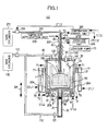
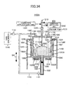
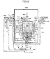
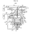
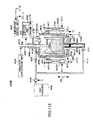
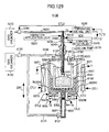
- Figure 1 is a schematic cross-sectional diagram showing the construction of a crystal growth apparatus according to Embodiment 1 of the present invention.
- a crystal growth apparatus 100 comprises: a crucible 10; a reaction vessel 20; conduits 30 and 200; a bellows 40; a support unit 50; a stopper/inlet plug 60; heating units 70 and 80; temperature sensors 71 and 81; gas supply lines 90, 110, 250, valves 120, 121, 160; a pressure regulator 130; gas cylinders 140 and 270; an evacuation line 150; a vacuum pump 170; a pressure sensor 180; a metal melt 190; a thermocouple 210; an up/down mechanism 220; a vibration applying unit 230; a vibration detection unit 240; a flow meter 260; and a temperature control unit 280.
- the crucible 10 has a generally cylindrical form and is formed of boron nitride (BN).
- the reaction vessel 20 is disposed around the crucible with a predetermined separation from the crucible 10. Further, the reaction vessel 20 is formed of a main part 21 and a lid 22. Each of the main part 21 and the lid 22 is formed of SUS316L stainless steel, wherein a metal seal ring is provided between the main part 21 and the lid 22 for sealing. Thus, there occurs no leakage of a melt mixture 290 to be described later to the outside.
- the conduit 30 is connected to the reaction vessel 20 at the underside of the crucible 10 in terms of a gravitational direction DR1.
- the bellows 40 is connected to the reaction vessel 10 at the upper side of the crucible 10 in terms of a gravitational direction DR1.
- the support substrate 50 comprises a hollow cylindrical member and a part thereof is inserted into a space 23 inside the reaction vessel 20 via the bellows 40.
- the stopper/inlet plug 60 may be formed of a metal, ceramic, or the like, for example, and is held inside the conduit 30 at a location lower than the connection part of the reaction vessel 20 and the conduit 30.
- the heating unit 70 is disposed so as to surround the outer circumferential surface 20A of the reaction vessel 20.
- the heating unit 80 is disposed so as to face a bottom surface 20B of the reaction vessel 20.
- the temperature sensors 71 and 81 are disposed in the close proximity of the heating units 70 and 80, respectively.
- the gas supply line 90 has an end connected to the reaction vessel 20 via the valve 120 and the other end connected to the gas cylinder 140 via the pressure regulator 130.
- the gas supply line 110 has an end connected to the conduit 30 via the valve 121 and the other end connected to the gas supply line 90.
- the valve 120 is connected to the gas supply line 90 in the vicinity of the reaction vessel 20.
- the valve 121 is connected to the gas supply line 110 in the vicinity of the conduit 30.
- the pressure regulator 130 is connected to the gas supply line 90 in the vicinity of the gas cylinder 140.
- the gas cylinder 140 is connected to the gas supply line 90.
- the evacuation line 150 has an end connected to the reaction vessel 20 via the valve 160 and the other end connected to the vacuum pump 170.
- the valve 160 is connected to the evacuation line 150 in the vicinity of the reaction vessel 20.
- the vacuum pump 170 is connected to the evacuation line 150.
- the pressure sensor 180 is mounted to the reaction vessel 20.
- the metal melt 190 comprises a melt of metal sodium (metal Na) and is held between the crucible 10 and the reaction vessel 20 and inside the conduit 30.
- the conduit 200 and the thermocouple 210 are inserted into the interior of the support unit 50.
- the up/down mechanism 220 is mounted upon the support unit 50 at the location above the bellows 40.
- the gas supply line 250 has an end connected to the conduit 200 and the other end connected to the gas cylinder 270 via the flow meter 260.
- the flow meter 260 is connected to the gas supply line 250 in the vicinity of the gas cylinder 270.
- the gas cylinder 270 is connected to the gas supply line 250.
- the crucible 10 holds the melt mixture 290 containing metal Na and metal gallium (metal Ga).
- the reaction vessel 20 surrounds the crucible 10.
- the conduit 30 leads the nitrogen gas (N2 gas) supplied from the gas cylinder 140 via the gas supply lines 90 and 110 to the stopper/inlet plug 60.
- the bellows 40 holds the support unit 50 and disconnects the interior of the reaction vessel 20 from outside. Further, the bellows 40 is capable of expanding and contracting in the gravitational direction DR1 with movement of the support unit 50 in the gravitational direction DR1.
- the support unit 50 supports a seed crystal 5 of a GaN crystal at a first end thereof inserted into the reaction vessel 20.
- the stopper/inlet plug 60 has a dimple structure on the outer peripheral surface such that there are formed apertures of the size of several ten microns between the inner wall of the conduit 30 and the stopper/inlet plug 60.
- the stopper/inlet plug 60 allows the nitrogen gas in the conduit 30 to pass in the direction to the metal melt 190 and supplies the nitrogen gas to the space 23 via the metal melt 190.
- the stopper/inlet plug 60 holds the metal melt 190 between the crucible 10 and the reaction vessel 20 and further inside the conduit 30 by the surface tension caused by the apertures of the size of several ten microns.
- the heating unit 70 comprises a heater and a current source.
- the heating unit 70 supplies, in response to a control signal CTL1 from the temperature control unit 280, a current from the current source to the heater and heats the crucible 10 and the reaction vessel 20 to a crystal growth temperature from the outer peripheral surface 20A of the reaction vessel 20.
- the temperature sensor 71 detects a temperature of the heater of the heating unit 70 and outputs a detected temperature signal indicative of the detected temperature T1 to the temperature control unit 280.
- the heating unit 80 also comprises a heater and a current source.
- the heating unit 80 supplies, in response to a control signal CTL2 from the temperature control unit 280, a current from the current source to the heater and heats the crucible 10 and the reaction vessel 20 to a crystal growth temperature from the bottom surface 20B of the reaction vessel 20.
- the temperature sensor 81 detects a temperature T2 of the heater of the heating unit 80 and outputs a temperature signal indicative of the detected temperature T2 to the temperature control unit 280.
- the gas supply line 90 supplies the nitrogen gas supplied from the gas cylinder 140 via the pressure regulator 130 to the interior of the reaction vessel 20 via the valve 120.
- the gas supply line 110 supplies the nitrogen gas supplied from the gas cylinder 140 via the pressure regulator 130 to the interior of the conduit 30 via the valve 121.
- the valve 120 supplies the nitrogen gas inside the gas supply line 90 to the interior of the reaction vessel 20 or interrupts the supply of the nitrogen gas to the interior of the reaction vessel 20.
- the valve 121 supplies the nitrogen gas inside the gas supply line 110 to the conduit 30 or interrupts the supply of the nitrogen gas to the conduit 30.
- the pressure regulator 130 supplies the nitrogen gas from the gas cylinder 140 to the gas supply lines 90 and 110 after setting the pressure to a predetermined pressure.
- the gas cylinder 140 holds the nitrogen gas.
- the evacuation line 150 passes the gas inside the reaction vessel 20 to the vacuum pump 170.
- the valve 160 connects the interior of the reaction vessel 20 and the evacuation line 150 spatially or disconnects the interior of the reaction vessel 20 and the evacuation line 150 spatially.
- the vacuum pump 170 evacuates the interior of the reaction vessel 20 via the evacuation line 150 and the valve 160.
- the pressure sensor 180 detects the pressure inside the reaction vessel 20.
- the metal melt 190 supplies the nitrogen gas introduced through the stopper/inlet plug 60 into the space 23.
- the conduit 200 cools the seed crystal 5 by releasing the nitrogen gas supplied from the gas supply line 250 into the support unit 50 from the first end thereof.
- the thermocouple 210 detects a temperature T3 of the seed crystal 5 and outputs a temperature signal indicative of the detected temperature T3 to the temperature control unit 280.
- the up/down mechanism 220 causes the support unit 50 to move up or down in response to a vibration detection signal BDS from the vibration detection unit 240 according to a method to be explained later, such that the seed crystal 5 makes a contact with a vapor-liquid interface 3 between the space 23 and the melt mixture 290.
- the vibration application unit 230 comprises a piezoelectric element, for example, and applies a vibration of predetermined frequency to the support unit 50.
- the vibration detection unit 240 comprises an acceleration pickup, for example, and detects the vibration of the support unit 50 and outputs the vibration detection signal BDS indicative of the vibration of the support unit 50 to the up/down mechanism 220.
- the gas supply line 250 supplies a nitrogen gas supplied from the gas cylinder 270 via the flow meter 260 to the conduit 200.
- the flow meter 260 supplies the nitrogen gas supplied from the gas cylinder 270 to the gas supply line 250 with flow rate adjustment in response to a control signal CTL3 from the temperature control unit 280.
- the gas cylinder 270 holds the nitrogen gas.
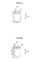
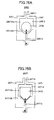
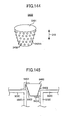
- Figure 2 is an oblique view diagram showing the construction of the stopper/inlet plug 60 shown in Figure 1.
- the stopper/inlet plug 60 includes a plug 61 and projections 62.
- the plug 61 has a generally cylindrical form.
- the projection 62 has a generally semi-circular cross-sectional shape and the projections 62 are formed on the outer peripheral surface of the plug 61 so as to extend in a length direction DR2.
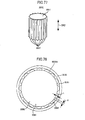
- Figure 3 is a plan view diagram showing the state of mounting the stopper/inlet plug 60 to the conduit 30.
- the projections 62 are formed with plural number in the circumferential direction of the plug 61 with an interval d of several ten microns. Further, each projection 62 has a height H of several ten microns.
- the plural projections 62 of the stopper/inlet plug 60 make a contact with the inner wall surface 30A of the conduit 30. With this, the stopper/inlet plug 60 is in engagement with the inner wall of the conduit 30.
- the projections 62 have a height H of several ten microns and are formed on the outer peripheral surface of the plug 61 with the interval d of several ten microns, there are formed plural gaps 63 between the stopper/inlet plug 60 and the inner wall 30A of the conduit 30 with a diameter of several ten microns in the state the stopper/inlet plug 60 is in engagement with the inner wall 30A of the conduit 30.
- This gap 63 allows the nitrogen gas to pass in the length direction DR2 of the plug 61 and holds the metal melt 190 at the same time by the surface tension of the metal melt 190, and thus, the metal melt 190 is blocked from passing through the gap in the longitudinal direction DR2 of the plug 61.
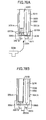
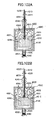
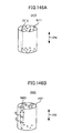
- FIGS 4A and 4B are enlarged diagrams of the support unit 50, the conduit 200 and the thermocouple 210 shown in Figure 1.
- the support unit 50 includes a cylindrical member 51 and fixing members 52 and 53.
- the cylindrical member 51 has a generally circular cross-sectional form.
- the fixing member 52 has a generally L-shaped cross-sectional form and is fixed upon an outer peripheral surface 51A and a bottom surface 51B of the cylindrical member 51 at the side of a first end 511 of the cylindrical member 51.
- the fixing member 53 has a generally L-shaped cross-sectional form and is fixed upon the outer peripheral surface 51A and the bottom surface 51B of the cylindrical member 51 at the side of a first end 511 of the cylindrical member 51 in symmetry with the fixing member 52.
- the conduit 200 has a generally circular cross-sectional form and is disposed inside the cylindrical member 51.
- the bottom surface 200A of the conduit 200 is disposed so as to face the bottom surface 51B of the cylindrical member 51.
- plural apertures 201 are formed on the bottom surface 200A of the conduit 200.
- thermocouple 210 is disposed inside the cylindrical member 51 such that a first end 210A thereof is adjacent to the bottom surface 51B of the cylindrical member 51. Reference should be made to Figure 4A.
- the seed crystal 5 has a shape that fits the space 54 and is held by the support unit 50 by being fitted into the space 54. In the present case, the seed crystal 5 makes a contact with the bottom surface 51B of the cylindrical member 51. Reference should be made to Figure 4B.
- thermocouple 210 detects the temperature T3 of the seed crystal 5 by the thermocouple 210 and it becomes also possible to cool the seed crystal 5 easily by the nitrogen gas directed to the bottom surface 51B of the cylindrical member 51 from the conduit 200.
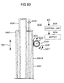
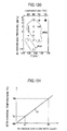
- Figure 5 is a schematic diagram showing the construction of the up/down mechanism 220 shown in Figure 1.
- the up/down mechanism 220 comprises a toothed member 221, a gear 222, a shaft member 223, a motor 224 and a control unit 225.
- the toothed member 221 has a generally triangular cross-sectional shape and is fixed upon the outer peripheral surface 51A of the cylindrical member 51.
- the gear 222 is fixed upon an end of the shaft member 223 and meshes with the toothed member 221.
- the shaft member 223 has the foregoing end connected to the gear 222 and the other end connected to a shaft (not shown) of the motor 224.
- the motor 224 causes the gear 222 to rotate in the direction of an arrow 226 or an arrow 227 in response to control from the control unit 225.
- the control unit 225 controls the motor 224 based on the vibration detection signal BDS from the vibration detection unit 240 and causes the gear 222 to rotate in the direction of the arrow 226 or 227.
- rotation of the gear 222 in the direction of the arrow 226 or 227 corresponds to a movement of the support unit 50 up or down in terms of the gravitational direction DR1.
- Figure 6 is a timing chart of the vibration detection signal BDS.
- the vibration detection signal BDS detected by the vibration detection unit 240 comprises a signal component SS1 in the case the seed crystal 5 is not in contact with the melt mixture 290, while in the case the seed crystal 5 is in contact with the melt mixture 290, the vibration detection signal BDS is formed of a signal component SS2. Further, in the case the seed crystal 5 is dipped into the melt mixture 290, the vibration detection signal BDS is formed of a signal component SS3.
- the seed crystal 5 In the event the seed crystal 5 is not in contact with the melt mixture 290, the seed crystal 5 is vibrated vigorously by the the vibration applied by the vibration application unit 230 and the vibration detection signal BDS is formed of the signal component SS1 of relatively large amplitude.
- the vibration detection signal BDS is formed of the signal component SS2 of relatively small amplitude.
- vibration of the seed crystal 5 becomes more difficult because of the viscosity of the melt mixture 290, and the vibration detection signal BDS is formed of the signal component SS3 of further smaller amplitude than the signal component SS2.
- the control unit 225 detects, upon reception of the vibration detection signal from the vibration detection unit 240, the signal component in the vibration detection signal BDS.
- the control unit 225 controls the motor 224 such that the support unit 50 is lowered in the gravitational direction DR1, until the signal component SS2 is detected for the signal component of the vibration detection signal BDS.
- control unit 225 controls the motor 224 such that the gear 222 is rotated in the direction of the arrow 227, and the motor 224 causes the gear 222 to rotate in the direction of the arrow 227 in response to the control from the control unit 225 via the shaft member 223. With this, the support member 50 moves in the downward direction in terms of the gravitational direction.
- control unit 225 controls the motor 224 such that the rotation of the gear 222 is stopped when the signal component of the vibration detection signal BDS received from the vibration detection unit 240 has changed from the signal component SS1 to the signal component SS2, and the motor stops the rotation of the gear 222 in response to the control from the control unit 225.
- the support unit 50 stops the movement thereof and the seed crystal 5 is held at the vapor-liquid interface 3.
- control unit 225 controls the motor 224, when received the vibration detection signal BDS formed of the signal component SS2 from the vibration detection unit 240, such that the movement of the support unit 50 is stopped.
- the seed crystal 5 is already in contact with the melt mixture 290.
- the up/down mechanism 220 moves the support unit 50 in the gravitational direction DR1 based on the vibration detection signal BDS detected by the vibration detection unit 240, such that the seed crystal 5 is in contact with the melt mixture 290.
- Figure 7 is a timing chart showing the temperature of the crucible 10 and the reaction vessel 20.
- Figure 8 is a schematic diagram showing the state inside the crucible 10 and the reaction vessel 20 during the interval between two timings t1 and t2 shown in Figure 7.
- Figure 9 is a diagram showing the relationship between the temperature of the seed crystal 5 and the flow rate of the nitrogen gas.
- the heating units 79 and 80 heat the crucible 10 and the reaction vessel 20 such that the temperatures thereof rise along the line k1 and is held at 800°C.
- the temperatures of the crucible 10 and the reaction vessel 20 start to rise and reach a temperature of 98°C at the timing t1 and a temperate of 800°C at the timing t2.
- the up/down mechanism 220 moves the support unit 50 up or down according to the method explained above in response to the vibration detection signal BDS from the vibration detection unit 240 and maintains the seed crystal 5 in contact with the melt mixture 290.
- the nitrogen gas 4 in the space 23 is incorporated into the melt mixture 290 via the meditating metal Na.
- the concentration of nitrogen or GaxNy (x, y are real numbers) in the melt mixture 290 takes the maximum value in the vicinity of the vapor-liquid interface 3 between the space 23 and the melt mixture 290, and thus, growth of the GaN crystal starts from the seed crystal 5 in contact with the vapor-liquid interface 3.
- GaxNy will be designated as "group III nitride” and the concentration of GaxNy will be designated as "concentration of group III nitride”.
- group III means "group IIIB” as defined in a periodic table of IUPAC (International Union of Pure and Applied Chemistry).
- the temperature T3 of the seed crystal 5 is 800°C and equal to the temperature of the melt mixture 290, while in the present embodiment, the seed crystal 5 is cooled by supplying a nitrogen gas to the inside of the conduit 200 for increasing the degree of supersaturation of nitrogen in the melt mixture 290 in the vicinity of the seed crystal 5.
- the temperature T3 of the seed crystal 5 is set lower than the temperature of the melt mixture 290.
- the temperature T3 of the seed crystal 5 is set to a temperature Ts1 lower than 800°C along the curve k2 after the timing t2.
- This temperature Ts1 may be a temperature of 790°C.
- the temperature control unit 280 When the temperatures T1, T2 and T3 as measured by the temperature sensors 71 and 81 and the thermocouple 210 have reached 800°C, the temperature control unit 280 produces a control signal CTL3 for causing to flow a nitrogen gas with an amount such that the temperature T3 of the seed crystal 5 is set to the temperature Ts1, and supplies the control signal CTL3 to the flow meter 260.
- the flow meter causes to flow a nitrogen gas from the gas cylinder to the conduit 200 via the gas supply line 250 in response to the control signal CTL3 with a flow rate that sets the temperature T3 to the temperature Ts1.
- the temperature of the seed crystal 5 is lowered from 800°C generally in proportion to the flow rate of the nitrogen gas, and the temperature T3 of the seed crystal 5 is set to the temperature Ts1 when the flow rate of the nitrogen gas has reaches a flow rate value fr1 (sccm).
- the flow meter 260 causes the nitrogen gas to the conduit 200 with the flow rate value fr1.
- the nitrogen gas thus supplied to the conduit 200 hits the bottom surface 51B of the cylindrical member 51 via the plural apertures 201 of the conduit 200.
- the seed crystal 5 is cooled via the bottom surface 51B of the cylindrical member 51 and the temperature T3 of the seed crystal 5 is lowered to the temperature Ts1 with the timing t3. Thereafter, the seed crystal 5 is held at the temperature Ts1 until a timing t4.
- the temperature control unit 280 controls the heating units 70 and 80, when the temperature T3 of the seed crystal 5 starts to go down from 800°C, by using the control signals CTL1 and CTL2 such that the temperatures T1 and T2 as measured by the temperature sensors 71 and 81 become the temperatures in which the crucible 10 and the reaction vessel 20 are set to 800°C.
- the temperature T3 of the seed crystal 5 is controlled, after the timing t2, such that the temperature is lowered along the line k3.
- the temperature T3 of the seed crystal 5 is lowered from 800°C to the temperature Ts2 ( ⁇ Ts1) during the interval from the timing t2 to the timing t4.
- the flow meter 260 increases the flow rate of the nitrogen gas supplied to the conduit 200 from 0 to a flow rate value fr2 along a line k4 based on the control signal CTL3 from the temperature control unit 280.
- the temperature T3 of the seed crystal 5 is set to a temperature Ts2 lower than the temperature Ts1.
- the temperature Ts2 may be chosen to 750°C.
- the first reason is that it becomes difficult to set the temperature of the GaN crystal grown from the seed crystal 5 below the temperature of the melt mixture 290 because there occurs adhesion of GaN crystal on the seed crystal 5 with progress of crystal growth of the GaN crystal, unless the unless the temperature of the seed crystal 5 is lowered gradually.
- the state of supersaturation is maintained with regard to nitrogen or group III nitride in the melt mixture 290 at least in the vicinity of the seed crystal 5, and it becomes possible to maintain the growth rate of the GaN crystal. As a result, it becomes possible to increase the size of the GaN crystal.
- a GaN crystal grown in the crystal growth apparatus 100 without using the seed crystal 5 is used for the seed crystal 5.
- Figure 10 is a diagram showing the relationship between the nitrogen gas pressure and the crystal growth temperature for the case of growing a GaN crystal.
- the horizontal axis represents the crystal growth temperature while the vertical axis represents the nitrogen gas pressure.
- a region REG represents a region in which a columnar GaN crystal grown in a c-axis direction ( ⁇ 0001> direction) is obtained at the bottom surface and sidewall surface of the crucible 10 exposed to the melt mixture 290.
- GaN crystals are grown by using the nitrogen gas pressure and crystal growth temperature of the region REG.
- numerous nuclei are formed on the bottom surface and sidewall surface of the crucible 10 and columnar GaN crystals grown in the c-axis direction are obtained.
- the seed crystal 5 is formed by slicing out the GaN crystal of the shape shown in Figures 4A and 4B from numerous GaN crystals formed as a result of the crystal growth process.
- a projecting part 5A of the seed crystal shown in Figure 4B is formed of a GaN crystal grown in the c-axis direction ( ⁇ 0001> direction).
- the seed crystal 5 thus formed is fixed upon the support unit 50 by fitting into the space 54 of the support unit 50.
- Figure 11 is a diagram showing calculation of the amount of metal Na to be loaded into the crystal growth apparatus 100 shown in Figure 1 in Embodiment 1.
- the volume V1 of the metal melt 190 held between the crucible 10 and the reaction vessel 20 and in the conduit 30 is represented by the equation below, where it should be noted that the volume of the reaction vessel 20 for the part thereof located underneath the vapor-liquid interface is designated as A; the volume of the crucible 10 is designated as B; and the volume inside the conduit 20 for the part located above the stopper/inlet plug 60 is designated as C.
- V ⁇ 1 A - B + C
- the reaction vessel 20 has an inner diameter ⁇ 1 of 11.6cm
- the conduit 30 has an inner diameter ⁇ 3 of 0.94cm
- the crucible 10 has a height H1 of 10.0cm
- the metal melt 190 held underneath the crucible 10 has a heihg H2 of 0.5cm
- the metal melt 190 held in the reaction vessel 20 has a height H3 of 8.5cm
- the metal melt 190 held inside the reaction vessel 20 has a height H4 of 20.0cm
- the volume A becomes 898.3cm 3
- the volume B becomes 628.3 cm 3
- the volume C becomes 55.5cm 3 .
- the molar number of Na occupying the volume of 325.5cm 3 in the liquid state is obtained.
- the molar number of Na occupying the volume of 325.5cm 3 becomes 11mol.
- M1 stands for the amount of the metal Na loaded into the reaction vessel 20
- M2 stands for the amount of the Na existing in the space 23 in the form of vapor at a temperature equal to or higher then the melting temperature of metal Na.
- Figure 12 is another diagram showing calculation of the amount of the metal Na to be loaded into the crystal growth apparatus 100 shown in Figure 1 in Embodiment 1.
- the Na evaporated from the metal melt 190 is formed of the Na existing in the space 23 in the form of the metal Na vapor 7 and the Na collected in the low temperature region 24 in the form of liquid.
- designating the amount of the Na collected in the low temperature region 24 as M4 the metal Na vapor 7 evaporated from the melt mixture 290 to the space 23 cannot cause diffusion to the outside when the following relationship holds.
- the crystal growth apparatus it is a conduit (not shown) for mounting a release valve for lowering the pressure of the bellows 40 or the reaction vessel 20 which forms the low temperature region 24 adjacent to the space 23.
- the bellows 40 has a form of a cylinder having an outer diameter of 2.8cm and a height of 10cm
- the volume of the bellows 40 becomes 60cm 3 .
- the volume of the conduit for mounting the release valve may be 0.6cm 3 where it is assumed that the conduit has an inner diameter of 0.4cm and a length of 5cm.
- crystal growth of GaN is achieved by loading metal Na into the reaction vessel 20 with the amount M1 having any of the relationships explained above with reference to Equations (2) - (5).
- Figure 13 is a flowchart explaining the manufacturing method of the GaN crystal according to Embodiment 1 of the present invention.
- the crucible 10 and the reaction vessel 20 are incorporated into a glove box filled with an Ar gas when a series of processes are started. Further, metal Na and metal Ga are loaded into the crucible 10 in an Ar gas ambient (Step S1). In the present case, the metal Na and the metal Ga are loaded into the crucible 10 with a molar ratio of 5:5.
- the Ar gas should be the one having a water content of 10ppm or less and an oxygen content of 10ppm or less (this applied throughout the present invention).
- metal Na is loaded between the crucible 10 and the reaction vessel 20 in the Ar gas ambient with an amount such that metal Na can exist between the space 23 and the outside in the form of liquid at the temperature equal to or higher than the melting temperature of metal Na (Step S2).
- metal Na is loaded between the crucible 10 and the reaction vessel 20 with the amount M1, which is larger than the amount M2 of Na existing in the space 23 in the form of vapor at the temperature equal to or higher than the melting temperature of metal Na in the case Equation (2) explained above holds.
- the metal Na is loaded between the crucible 10 and the reaction vessel 20 with the amount M1 larger than the sum of the amount M2 of Na existing in the space 23 in the form of vapor at the temperature equal to or higher than the melting temperature of metal Na and the amount M3 of Na solidified and adhered to the stopper/inlet plug 60.
- the metal Na is loaded between the crucible 10 and the reaction vessel 20 with the amount M1 larger than the sum of the amount M2 of Na existing in the space 23 in the form of vapor at the temperature equal to or higher than the melting temperature of metal Na and the amount M4 of Na collected in the low temperature region 24 in the form of liquid.
- the metal Na is loaded between the crucible 10 and the reaction vessel 20 with the amount M1 larger than the sum of the amount M2 of Na existing in the space 23 in the form of vapor at the temperature equal to or higher than the melting temperature of metal Na, the amount M3 of Na solidified and adhered to the stopper/inlet plug 60, and the amount M4 of Na collected in the low temperature region 24 in the form of liquid.
- the seed crystal 5 is set at a location above the metal Na and metal Ga in the crucible 10 in the Ar gas ambient (step S3). More specifically, the seed crystal 5 is set above the metal Na and metal Ga in the crucible 10 by fitting the seed crystal 5 to the space 54 formed at the end 511 of the support unit 50. Reference should be made to Figure 4B.
- the crucible 10 and the reaction vessel 20 are set in the crystal growth apparatus 100 in the state that the crucible 10 and the reaction vessel 20 are filled with the Ar gas.
- the valve 160 is opened and the Ar gas filled in the crucible 10 and the reaction vessel 20 is evacuated by the vacuum pump 170.
- the valve 160 is closed and the valves 120 and 121 are opened.
- the crucible 10 and the reaction vessel 20 are filled with the nitrogen gas from the gas cylinder 140 via the gas supply lines 90 and 110.
- the nitrogen gas is supplied to the crucible 10 and the reaction vessel 20 via the pressure regulator 130 such that the pressure inside the crucible 10 and the reaction vessel 20 becomes about 0.1MPa.
- the valves 120 and 121 are closed and the valve 160 is opened.
- the nitrogen gas filled in the crucible 10 and the reaction vessel 20 is evacuated by the vacuum pump 170.
- the interior of the crucible 10 and the reaction vessel 20 is evacuated to a predetermined pressure (0.133Pa or less) by using the vacuum pump 170.
- the interiors of the crucible 10 and the reaction vessel 20 are evacuated to a predetermined pressure by the vacuum pump 170, and the valve 160 is closed. Further, the valves 120 and 121 are opened and the nitrogen gas is filled into the crucible 10 and the reaction vessel 20 by the pressure regulator 130 such that the pressure of the crucible 10 and the reaction vessel 20 becomes the range of 1.01 - 5.05MPa.
- the nitrogen gas is supplied to the space 23 inside the reaction vessel 20 also from the space 31 of the conduit 30 via the stopper/inlet plug 60.
- the valve 120 is closed.
- the crucible 10 and the reaction vessel 20 are heated to 800°C by the heating units 70 and 80 (step S5).
- the metal melt Na held between the crucible 10 and the reaction vessel 20 undergoes melting in view of the melting temperature of metal Na of about 98°C, and the metal melt 190 is formed.
- two vapor-liquid interfaces 1 and 2 are formed.
- the vapor-liquid interface 1 is located at the interface between the metal melt 190 and the space 23 in the reaction vessel 20, while the vapor-liquid interface 2 is located at the interface between the metal melt 190 and the stopper/inlet plug 60.
- the temperature of the stopper/inlet plug 60 becomes 150°C.
- the up/down mechanism 220 causes the seed crystal 5 to make a contact with the melt mixture 290 (step S6).
- the nitrogen gas in the space 23 is incorporated into the melt mixture 290 via the metal Na in the melt mixture 290, and there starts the growth of GaN crystal from the seed crystal 5.
- the nitrogen gas in the space 23 is consumed and there is caused a decrease of the nitrogen gas in the space 23.
- the pressure P1 of the space 23 becomes lower than the pressure P2 of the space 31 inside the conduit 30 (P1 ⁇ P2), and there is formed a differential pressure between the space 23 and the space 31.
- step S10 the seed crystal 5 is lowered so as to make a contact with the melt mixture 290 according to the method explained above. With this a GaN crystal of large size is grown.
- step S11 After the predetermined time has elapsed, the temperatures of the crucible 10 and the reaction vessel 20 are lowered (step S11), and manufacturing of the GaN crystal is completed.
- Figure 14 is a schematic diagram showing the state inside the crucible 10 and the reaction vessel 20 in the step S9 shown in Figure 13.
- the temperatures of the crucible 10 and the reaction vessel 20 are held at 800°C during the interval from the timing t2 to the timing t4, and growth of the GaN crystal proceeds in the melt mixture 290. Further, with progress of growth of the GaN crystal, there occurs evaporation of metal Na from the metal melt 190 and the melt mixture 290, and thus, there exist a mixture of the nitrogen gas 4 and the metal Na vapor 7 in the space 23.
- the pressure P1 of the space 23 is lowered than the pressure P2 of the space 31 inside the conduit 30. Then the nitrogen gas is supplied from the space 31 of the conduit 30 to the metal melt 190 via the stopper/inlet plug 60 and moves through the metal melt 190 in the form of bubbles 191. Thus, the nitrogen gas is supplied to the space 23 through the vapor-liquid interface 1. Now, when the pressure P1 of the space 23 becomes generally equal to the pressure P2 inside the space 31, the supply of the nitrogen gas from the space 31 of the conduit 30 to the crucible 20 and the reaction vessel 20 via the stopper/inlet plug 60 and the metal melt 190 is stopped.
- the stopper/inlet plug 60 is formed of a structure that blocks passage of the metal melt 190 therethrough.
- Figure 15 is a schematic diagram showing the state inside the crucible 10 and the reaction vessel 20 in the step S10 shown in Figure 13.
- the vibration detection signal BDS is formed solely by the component SS1 (see Figure 6), and thus, the up/down mechanism 220 lowers the support unit 50 in response to the vibration detection signal BDS such that the GaN crystal 6 makes a contact with the melt mixture 290. Thereby, the GaN crystal contacts with the metal mixture 290 again, and there occurs the preferential growth the GaN crystal 6.
- the seed crystal 5 or the GaN crystal 6 grown from the seed crystal 5 is made contact with the melt mixture 290 constantly during the growth of the GaN crystal. With this, it becomes possible to grow a GaN crystal of large size.
- the present invention can conduct growth of the GaN crystal in the state the metal Na vapor 7 is confined in the space 23, by loading the metal Na into the reaction vessel 20 with the amount M1 determined such that the metal Na of liquid state can exist between the crucible 10 and the reaction vessel 20 and in the conduit 30 at the temperature equal to or higher than the melting temperature of the metal Na (see the step S2).
- This GaN crystal is a defect-free crystal having a columnar shape grown in the c-axis direction ( ⁇ 0001> direction).
- the GaN crystal it is preferred to carry out the growth of the GaN crystal by loading the metal Na between the crucible 10 and the reaction vessel 20 with the amount M1 determined such that the location of the vapor-liquid interface 1 is coincident to the location of the vapor-liquid interface 3.
- the metal melt 190 liquid Na
- the seed crystal 5 is lowered by the up/down mechanism 220 with growth of the GaN crystal such that contact of the seed crystal 5 to the melt mixture 290 is maintained, it becomes possible to maintain the state in which the growth of the GaN crystal occurs preferentially from the seed crystal 5. As a result, it becomes possible to grow a GaN crystal of large size.
- the temperature T4 which is the temperature of the vapor-liquid interface 1 between the space 23 inside the reaction vessel and the metal liquid 190 or the temperature near the vapor-liquid interface 1
- the temperature T5 which is the temperature of the vapor-liquid interface 3 between the space 23 and the melt mixture 290 or the temperature near the vapor-liquid interface 3
- the vapor pressure of the metal Na evaporated from the metal melt 190 is generally identical with the vapor pressure of the metal Na evaporated from the melt mixture 290.
- the temperature T4 is set to be lower than the temperature T5 such that the vapor pressure of the metal Na evaporated from the metal melt 190 becomes generally identical with the vapor pressure of the metal Na evaporated from the melt mixture 290.
- the operation for making the seed crystal 5 to contact with the melt mixture 290 comprises the step A for applying a vibration to the support unit 50 by the vibration application unit 230 and detecting the vibration detection signal BDS indicative of the vibration of the support unit 50; and the step B of moving the support unit 50 by the up/down mechanism 220 such that the vibration detection signal changes to the state (component SS2 of the vibration detection signal BDS) corresponding to the situation where the seed crystal 5 has made contact with the melt mixture 290.
- the operation for holding the seed crystal 5 in the melt mixture 290 comprises the step A for applying a vibration to the support unit 50 by the vibration application unit 230 and detecting the vibration detection signal BDS indicative of the vibration of the support unit 50; and the step B of moving the support unit 50 by the up/down mechanism 220 such that the vibration detection signal changes to the state (component SS3 of the vibration detection signal BDS) corresponding to the situation where the seed crystal 5 been dipped into the melt mixture 290.
- step S10 of the flowchart shown in Figure 13 generally comprises a step D shown in Figure 13, wherein the step D moves the support unit 50 by the up/down mechanism 220 such that the GAN crystal grown from the seed crystal 5 makes a contact with the melt mixture 290 during the growth of the GaN crystal.
- the step D is defined as "moving the support unit 50 by the up/down mechanism 220".
- the operation for making the GaN crystal grown from the seed crystal 5 to contact with the melt mixture 290 comprises the step A and the step B noted above.
- the height H of the projection 62 of the stopper/inlet plug 60 and the separation d between the projections 62 may be determined by the temperature of the stopper/inlet plug 60. More specifically, when the temperature of the stopper/inlet plug 60 is relatively high, the height H of the projection 62 is set relatively higher and the separation d between the projections 62 is set relatively smaller. Further, when the temperature of the stopper/inlet plug 60 is relatively low, the height H of the projection 62 is set relatively lower and the separation d between the projections 62 is set relatively larger.
- the size of the gap 63 between the stopper/inlet plug 60 and the conduit 30 is set relatively small, while in the case the temperature of the stopper/inlet plug 60 is relatively high, the size of the gap 63 between the stopper/inlet plug 60 and the conduit 30 is set relatively larger.
- the size of the cap 63 is determined by the height H of the projection 62 and the separation d between the projections 62, while the size of the gap 63 capable of holding the metal melt 190 by the surface tension changes depending on the temperature of the stopper/inlet plug 60.
- the height H of the projection 62 and the separation d between the projections 62 are changed depending on the temperature of the stopper/inlet plug 60 and with this, the metal melt 190 is held reliably by the surface tension.
- the temperature control of the stopper/inlet valve 60 is achieved by the heating unit 80.
- the stopper/inlet plug 60 is heated by the heating unit 80.
- the present embodiment has been explained for the case in which the support unit 50 is applied with vibration and the seed crystal 5 or the GaN crystal 6 is controlled to make a contact with the melt mixture 260 while detecting the vibration of the support unit 50
- the present embodiment is not limited to such a construction and it is also possible to cause the seed crystal 5 or the GaN crystal 6 to make a contact with the melt mixture 290 by detecting the location of the vapor-liquid interface 3.
- an end of a conductor wire is connected to the reaction vessel 20 from the outside and the other end is dipped into the melt mixture 290. Further, an electric current is caused to flow through the conductor wire in this state and location of the vapor-liquid interface 3 is detected in terms of the length of the conductor wire in the reaction vessel 20 in which there has been noted a change of the current from Off to On.
- the up/down mechanism 220 lowers the seed crystal 5 or the GaN crystal 6 to the location of the detected vapor-liquid interface 3.
- thermocouple into the crucible 10 from the reaction vessel 20 and detect the location of the vapor-liquid interface 3 from the length of the thermocouple inserted into the reaction vessel 20 at the moment when the detected temperature has been changed.
- the metal melt 190 constitutes "the alkali metal melt”.
- gas cylinder 140 the pressure regulator 130, the gas supply lines 90 and 110, the conduit 30 and the stopper/inlet plug 60 form together the "gas supplying unit".
- Figure 16 is a schematic cross-sectional diagram showing the construction of a crystal growth apparatus according to Embodiment 2 of the present invention.
- the crystal growth apparatus 100A of Embodiment 2 has a construction similar to that of the crystal growth apparatus 100 except that the conduit 30 of the crystal growth apparatus 100 shown in Figure 1 is changed to conduits 300 and 310, the metal melt 190 is changed to a metal melt 330, and heating units 320 and 340 are added.
- the conduit 300 has an end connected to the reaction vessel 20.
- the conduit 310 has an end connected to the other end of the conduit 300 and the other end connected to the gas supply line 110.
- the heating unit 320 is provided so as to face the conduit 3000.
- the stopper/inlet plug 60 supplies the nitrogen gas supplied from the gas supply line 110 to the space 311 of the conduit 310 to the space 23 of the reaction vessel 20 via the metal melt 330 and via the space 301 of the conduit 300, and further holds the metal melt 330 inside the conduit 310 by the surface tension of the metal melt 330.
- the heating unit 320 heats the conduit 310 to the crystal growth temperature.
- the metal melt 330 supplies the nitrogen gas supplied from the space 311 via the stopper/inlet plug 60 to the space 23 inside the reaction vessel 20 and further confines the nitrogen gas and the metal Na vapor into the spaces 23, 301 and 312.
- the heating unit 340 heats the space 301 of the conduit 300 to the crystal growth temperature.
- Figure 17 is a diagram showing calculation of the amount of the metal Na to be loaded into the crystal growth apparatus 100A of Embodiment 2 shown in Figure 16.
- the volume V4 of the metal melt 330 held in the conduit 310 is represented by the equation below where the inner diameter of the conduit 310 is designated as ⁇ 4 and the height H5 of the metal melt 330 is designated as H5.
- V ⁇ 4 ⁇ ⁇ 4 / 2 2 ⁇ ⁇ H ⁇ 5 .
- the volume V4 is obtained from Equation (6) as 62.8cm 3 .
- the weight of Na having the value of 3.5cm 3 is given as 62.8cm 3 ⁇ 0.777g/cm 3 48.8g.
- V5 of the space 23 inside the reaction vessel 20 is represented by the equation below by using the volume B of the crucible 10 explained above.
- V ⁇ 5 V ⁇ 6 - B
- the vapor pressure P of Na at 850°C is 0.744(atm) and the volume V7 of the spaces 23, 301 and 312 is 1.726(L).
- the metal Na vapor 7 evaporated into the spaces 23, 301 and 312 from the melt mixture 290 cannot cause diffusion to the outside via the stopper/inlet plug 60 in the case the metal melt 330 ( liquid Na) exists between the space 23 and the stopper/inlet plug 60.
- Figure 18 is another diagram showing calculation of the amount of the metal Na to be loaded into the crystal growth apparatus 100A of Embodiment 2 shown in Figure 16.
- the Na evaporated from the metal melt 330 is formed of the Na existing in the spaces 23, 301 and 302 in the form of the metal Na vapor 7 and the Na collected in the low temperature region 24 in the form of liquid.
- designating the amount of the Na collected in the low temperature region 24 as M4 the metal Na vapor 7 evaporated from the melt mixture 290 to the space 23 cannot cause diffusion to the outside when the following relationship holds.
- the low temperature region 24 exposed to the space 23 has the volume of 60.6cm 3 as noted before.
- Na of the amount of 62.8cm 3 - 60.6cm 3 2.2cm 3 exists inside the conduit 310 in the form of liquid.
- Example 2 crystal growth of GaN is achieved by loading the metal Na into the conduit 310 with the amount M1 having any of the relationships explained above with reference to Equations (8) - (11).
- the metal Na is loaded into the conduit 310 with the amount M1 having any of the relationships explained above with reference to Equations (8) - (11) in the step S2.
- the heating units 320 and 340 are used to heat the conduits 310 and 300 to 800°C at the time of heating the crucible 10 and the reaction vessel 20 to 800°C.
- the temperatures of the crucible 10, the reaction vessel 20 and the conduits 300 and 310 are lowered. Otherwise, the process is the same as explained with reference to Figure 13.
- Embodiment 1 is identical to Embodiment 1.
- the volume of the crucible 10 becomes 441786cm 3 .
- the metal melt 190 liquid Na
- the volume of the space 23 is given as the volume of the reaction vessel 20 subtracted by the volume of the crucible, and thus, the volume of the space 23 becomes 1360000cm 3 .
- the diameter of the reaction vessel 20 having the volume of 1801786cm3 becomes 124cm.
- the present embodiment is not limited to the case of using the crucible 10 of the diameter of 4 inches but is the crystal growth apparatuses 100 and 100A of the present embodiment include also a crystal growth apparatus that uses the crucible having the diameter of 30 inches.
- the crystal growth apparatus of the present invention may be the one in which the conduit 200, the thermocouple 210, the gas supply line 250, the flow meter 260 and the gas cylinder 270 are removed from the crystal growth apparatuses 100 and 100A explained above.
- the crystal growth apparatus of the present invention may be the one in which the function of setting the temperature of the seed crystal 5 to be lower than the temperature of the melt mixture 290 is removed from the crystal growth apparatus 100 or 100A.
- the crystal growth temperature of the present invention may be the one in which the up/down mechanism 220, the vibration application unit 230 and the vibration detection unit 240 are removed from the crystal growth apparatuses 100 and 100A.
- the crystal growth apparatus of the present invention may be the one in which the function of moving the seed crystal 5 up or down is removed from the crystal growth apparatus 100 or 100A.
- the crystal growth apparatus of the present invention may be the one in which the conduit 200, the thermocouple 210, the up/down mechanism 220, the vibration application unit 230, the vibration detection unit 240, the gas supply line 250, the flow meter 260 and the gas cylinder 270 are removed from the crystal growth apparatuses 100 and 100A explained above.
- the crystal growth apparatus of the present invention may be the one in which the function of setting the temperature of the seed crystal 5 to be lower than the temperature of the melt mixture 290 and the function of moving the seed crystal 5 up or down are removed from the crystal growth apparatus 100 or 100A.
- the crystal growth apparatus of the present invention may be the one in which the support unit 50, the conduit 200, the thermocouple 210, the up/down mechanism 220, the vibration application unit 230, the vibration detection unit 240, the gas supply line 250, the flow meter 260 and the gas cylinder 270 are removed from the crystal growth apparatuses 100 and 100A explained above.
- the crystal growth apparatus of the present invention may be the one in which the function of supporting the seed crystal from the top side of the crucible 10, the function of setting the temperature of the seed crystal 5 to be lower than the temperature of the melt mixture 290, the function of moving the seed crystal 5 up or down are removed from the crystal growth apparatus 100 or 100A.
- the seed crystal 5 is disposed at the bottom part of the crucible 10.
- the present invention generally includes a crystal growth apparatus that includes the metal melt 190 (or metal melt 330) between the space 23 (or spaces 23, 301 and 302) exposed to the melt mixture 290 and an outside of the space, and a gas supply unit that supplies the nitrogen gas via the metal melt 190 (or the metal melt 330).
- the present embodiment generally includes the manufacturing method for manufacturing a GaN crystal that includes the step of loading metal Na into the space 23 (or space 23, 301 and 312) in an ambient of Ar gas with an amount such that the metal Na exists between the space 23 (or space 23, 301, 312) and the outside in the form of liquid at the temperature higher than the melting temperature of the metal Na.
- Figure 19 is another oblique view diagram of the stopper/inlet plug according to the present invention. Further, Figure 20 is a cross-sectional diagram showing the method for mounting the stopper/inlet plug 400 shown in Figure 19.
- the stopper/inlet plug 400 comprises a plug 401 and a plurality of projections 402.
- the plug 401 is formed of a cylindrical body that changes the diameter in a length direction DR3.
- Each of the projections 402 has a generally semispherical shape of the diameter of several ten microns.
- the projections 402 are formed on an outer peripheral surface 401A of the plug 401 in a random pattern. Thereby, the separation between adjacent two projections 402 is set to several ten microns.
- the stopper/inlet plug 400 is fixed to a connection part of the reaction vessel 20 and the conduit 30 by support members 403 and 403. More specifically, the stopper/inlet plug 400 is fixed by the support member 404 having one end fixed upon the reaction vessel 20 and by the support member 404 having one end fixed upon an inner wall surface of the conduit 30.
- the projections 402 may or may not contact with the reaction vessel 20 or the conduit 30.
- the separation between the projections and the reaction vessel 20 or the separation between the projections 402 and the conduit 30 is set such that the metal melt 190 can be held by the surface tension, and the stopper/inlet plug 400 is fixed in this state by the support members 403 and 404.
- the metal Na held between the crucible 10 and the reaction vessel 20 takes a solid form before heating of the crucible 10 and the reaction vessel 20 is commenced, and thus, the nitrogen gas supplied from the gas cylinder 140 can cause diffusion between the space 23 inside the reaction vessel 20 and the space 31 inside the conduit 30 through the stopper/inlet plug 400.
- the metal Na held between the crucible 10 and the reaction vessel 20 undergoes melting to form the metal melt 190, while the metal melt 190 functions to confined the nitrogen gas to the space 23.
- stopper/inlet plug 400 holds the metal melt 190 by the surface tension thereof such that the metal melt 190 does not flow out from the interior of the reaction vessel 30 to the space 31 of the conduit 30.
- the metal melt 190 and the stopper/inlet plug 400 confines the nitrogen gas and the metal Na vapor evaporated from the metal melt 190 and the melt mixture 290 into the space 23. As a result, evaporation of the metal Na from the melt mixture 290 is suppressed, and it becomes possible to stabilize the molar ratio of the metal Na and the metal Ga in the melt mixture 290.
- the pressure P1 of the space 23 becomes lower than the pressure P2 of the space 31 inside the conduit 30, and the stopper/inlet plug 400 supplies the nitrogen gas in the space 31 via the metal melt 190 by causing to flow the nitrogen gas therethrough in the direction toward the reaction vessel 20.
- the stopper/inlet plug 400 functions similarly to the stopper/inlet plug 60 explained before.
- the stopper/inlet plug 400 can be used in the crystal growth apparatuses 100 and 100A in place of the stopper/inlet plug 60.
- stopper/inlet plug 400 has the projections 402
- the stopper/inlet plug 400 does not have the projections 402.
- the stopper/inlet plug 400 is held by the support members such that the separation between the plug 401 and the reaction vessel 20 or the separation between the plug 401 and the conduit 30 becomes several ten microns.
- the separation between the stopper/inlet plug 400 (including both of the cases in which the stopper/inlet plug 400 carries the projections 402 and the case in which the stopper/inlet plug 400 does not carry the projections 402) and the reaction vessel 20 and between the stopper/inlet plug 400 and the conduit 30 according to the temperature of the stopper/inlet plug 400.
- the separation between the stopper/inlet plug 400 and the reaction vessel 20 or the separation between the stopper/inlet plug 400 and the conduit 30 is set relatively narrow when the temperature of the stopper/inlet plug 40 is relatively high.
- the separation between the stopper/inlet plug 400 and the reaction vessel 20 or the separation between the stopper/inlet plug 400 and the conduit 30 is set relatively large.
- the separation between the stopper/inlet plug 400 and the reaction vessel 20 or the separation between the stopper/inlet plug 400 and the conduit 30 that can hold the metal melt 190 changes depending on the temperature of the stopper/inlet plug 400.
- the separation between the stopper/inlet plug 400 and the reaction vessel 20 or the separation between the stopper/inlet plug 400 and the conduit 30 is changed in response to the temperature of the stopper/inlet plug 400 such that the metal melt 190 is held securely by the surface tension.
- the temperature control of the stopper/inlet valve 400 is achieved by the heating unit 80.
- the stopper/inlet plug 400 is heated by the heating unit 80.
- the gas cylinder 140, the pressure regulator 130, the gas supply lines 90 and 110, the conduit 30 and the stopper/inlet plug 400 form together the "gas supplying unit".
- Figures 21A and 21B are further oblique view diagrams of the stopper/inlet plug according to the present embodiment.
- the stopper/inlet plug 410 comprises a plug 411 formed with a plurality of penetrating holes 412.
- the plurality of penetrating holes 412 are formed in the length direction DR2 of the plug 411. Further, each of the plural penetrating holes 412 has a diameter of several ten microns (see Figure 21A).
- the stopper/inlet plug 420 comprises a plug 421 formed with plural penetrating holes 422.
- the plurality of penetrating holes 422 are formed in the length direction DR2 of the plug 421.
- Each of the penetrating holes 422 have a diameter that changes stepwise from a diameter r1, r2 and r3 in the length direction DR2.
- each of the diameters r1, r2 and r3 is determined in the range such as several microns to several ten microns in which the metal melt 190 can be held by the surface tension Reference should be made to Figure 21B.
- the stopper/inlet plug 420 it is sufficient that there is formed at least one penetrating hole 422. Further, it is sufficient that the diameter of the penetrating hole 422 is changed at least in two steps. Alternatively, the diameter of the penetrating hole 422 may be changed continuously in the length direction DR2.
- the stopper/inlet plug 410 or 420 can be used in the crystal growth apparatuses 100 and 100A in place of the stopper/inlet plug 60.
- stopper/inlet plug 420 is used in the crystal growth apparatus 100 or 100A in place of the stopper/inlet plug 60, it becomes possible to hold the metal melt 190 by the surface tension thereof by one of the plural diameters that are changed stepwise, and it becomes possible to manufacture a GaN crystal of large size without conducting precise temperature control of the stopper/inlet plug 420.
- the amount M1 of the metal Na loaded into the reaction vessel 20 is determined by taking into account the amount of Na that invades into the stopper/inlet plug 420 to the location of the diameters r1 and r2.
- the gas cylinder 140, the pressure regulator 130, the gas supply lines 90 and 110, the conduit 30 and the stopper/inlet plug 410 or 412 form together the "gas supplying unit".
- porous plug or check valve in place of the stopper/inlet plug 60.
- the porous plug may be the one formed of a sintered body of stainless steel powders.
- Such a porous plug has a structure in which there are formed a large number of pores of several ten microns.
- the porous plug can hold the metal melt 190 by the surface tension thereof similarly to the stopper/inlet plug 60 explained before.
- the check valve of the present invention may include both a spring-actuated check valve used for low temperature regions and a piston-actuated check valve used for high temperature regions.
- This piston-actuated check valve is a check valve of the type in which a piston guided by a pair of guide members is moved in the upward direction by the differential pressure between the pressure P1 of the space 31 and the pressure P2 of the space 23 for allowing the nitrogen gas in the space 31 to the space 23 through the metal melt 190 in the event the pressure P2 is higher than the pressure P1 and blocks the connection between the reaction vessel 20 and the conduit 20 by the self gravity when P1 ⁇ P2.
- this check valve can be used also in the high-temperature region.
- the seed crystal 5 is moved up or down depending on the relationship between the crystal growth rate of the GaN crystal and the lowering rate of the interface 3 for maintaining contact of the seed crystal 5 with the interface 3
- the vapor pressure of the metal Na evaporated from the metal melt 190 becomes higher than the vapor pressure of the metal Na evaporated from the melt mixture 290.
- the metal Na migrates from the metal melt 190 to the melt mixture 290 and there is caused rising of the interface 3.
- the support unit 210 up or down by the up/down mechanism 220 such that the GaN crystal grown from the seed crystal 5 makes contact with the interface 3 while taking into consideration of the effect of rising of the interface 3 caused by the migration of the metal Na from the metal melt 190 to the melt mixture 290.
- the metal Ga in the melt mixture 290 is consumed while this consumption of the metal Ga invites lowering of the interface.
- the present embodiment is not limited to this specific crystal growth temperature. It is sufficient when the crystal growth temperature is equal to or higher than 600°. Further, it is sufficient that the nitrogen gas pressure may be any pressure as long as crystal growth of the present invention is possible under the pressurized state of 0.4MPa or higher. Thus, the upper limit of the nitrogen gas pressure is not limited to 5.05MPa but a pressure of 5.05MPa or higher may also be used.
- metal Na and metal Ga are loaded into the crucible 20 in the ambient of Ar gas and the metal Na is loaded between the crucible 10 and the reaction vessel 20 in the ambient of Ar gas
- the inert gas or the nitrogen gas should have the water content of 10ppm or less and the oxygen content of 10ppm or less.
- the present embodiment is not limited to this particular case, but it is also possible to form the melt mixture 290 by mixing an alkali metal such as lithium (Li), potassium (K), or the like, or an alkali earth metal such as magnesium (Mg), calcium (Ca), strontium (Sr), or the like, with the metal Ga.
- an alkali metal such as lithium (Li), potassium (K), or the like
- an alkali earth metal such as magnesium (Mg), calcium (Ca), strontium (Sr), or the like
- nitrogen gas in place of the nitrogen gas, it is also possible to use a compound containing nitrogen as a constituent element such as sodium azide, ammonia, or the like. These compounds constitute the nitrogen source gas.
- Ga it is also possible to use a groupo III metal such as boron (B), aluminum (Al), indium (In), or the like.
- the crystal growth apparatus and method of the present invention is generally applicable to the manufacturing of a group III nitride crystal while using a melt mixture of an alkali metal or an alkali earth melt and a group III metal (including boron).
- the group III nitride crystal manufactured with the crystal growth apparatus or method of the present invention may be used for fabrication of group III nitride semiconductor devices including light-emitting diodes, laser diodes, photodiodes, transistors, and the like.
- the present invention provides a crystal growth apparatus that can positively prevent diffusion of the alkali metal to the outside.
- the present invention is applied to the method for manufacturing a group III nitride crystal while preventing the diffusion of the alkali metal to the outside positively.
- Figure 22 is a schematic cross-sectional diagram showing the construction of a crystal growth apparatus according to Embodiment 3 of the present invention.
- the crystal growth apparatus 1100 includes: a crucible 1010; a reaction vessel 1020; a conduit 1030; a bellow 1040; a stopper/inlet plug 1050; heaters 1060 and 1070; a gas supply liens 1090 and 1110; valves 1120, 1121 and 1160; a pressure regulator 1130; a gas cylinder 1140; an evacuation line 1150; a vacuum pump 1170; a pressure sensor 1180; a metal melt 1190; a support unit 1210; an up/down mechanism 1220; a vibration application unit 1230; a vibration detection unit 1240; a filler 1250; and a metal member 1260.
- the crucible 10 has a generally cylindrical form and is formed of boron nitride (BN).
- the reaction vessel 1020 is disposed around the crucible with a predetermined separation from the crucible 1010. Further, the reaction vessel 1020 is formed of a main part 1021, a lid 1022 and a support part 1024.
- Each of the main part 1021, the lid 1022 and the support part 1024 is formed of SUS316L stainless steel, wherein a metal seal ring is provided between the main part 1021 and the lid 1022 for sealing.
- the support part 1024 is provided on the outer peripheral surface 1021A of the main part 201 for the part close to the lid 1022.
- the conduit 1030 is connected to the reaction vessel 1020 at the underside of the crucible 1010 in terms of a gravitational direction DR1.
- the bellows 1040 is connected to the reaction vessel 1020 at the upper side of the crucible 1010 in terms of a gravitational direction DR1.
- the stopper/inlet plug 1050 may be formed of a metal, ceramic, or the like, for example, and is held inside the conduit 1030 at a location lower than the connection part of the reaction vessel 1020 and the conduit 1030.
- the heater 1060 is disposed so as to surround the outer circumferential surface 1020A of the reaction vessel 1020.
- the heater 1070 is disposed so as to face a bottom surface 1020B of the reaction vessel 1020.
- the gas supply line 1090 has an end connected to the reaction vessel 1020 via the valve 1120 and the other end connected to the gas cylinder 1140 via the pressure regulator 1130.
- the gas supply line 1110 has an end connected to the conduit 1030 via the valve 1121 and the other end connected to the gas supply line 1090.
- the valve 1120 is connected to the gas supply line 1090 in the vicinity of the reaction vessel 1020.
- the valve 1121 is connected to the gas supply line 1110 in the vicinity of the conduit 1030.
- the pressure regulator 1130 is connected to the gas supply line 1090 in the vicinity of the gas cylinder 1140.
- the gas cylinder 1140 is connected to the gas supply line 1090.
- the evacuation line 1150 has an end connected to the reaction vessel 1020 via the valve 1160 and the other end connected to the vacuum pump 1170.
- the valve 1160 is connected to the evacuation line 1150 in the vicinity of the reaction vessel 1020.
- the vacuum pump 1170 is connected to the evacuation line 1150.
- the pressure sensor 1180 is mounted to the reaction vessel 1020.
- the metal melt 1190 comprises a melt of metal sodium (metal Na) and is held between the crucible 1010 and the reaction vessel 1020 and inside the conduit 1030.
- the support substrate 1210 comprises a cylindrical member and a part thereof is inserted into a space 1023 inside the reaction vessel 1020 via the bellows 1040.
- the up/down mechanism 1220 is mounted upon the support unit 1210 at the location above the bellows 1040.
- the filler 1250 is disposed at the outer side of the heaters 1060 and 1070.
- the metal member 1260 comprises SUS316L and has a hollow cylindrical form. Thereby, the metal member 1260 is disposed at the outer side of the filler 1250 in the state that an end thereof is supported by the support part 1024 while the other end of the metal member 1260 is opened. Thereby, the other end is located at a lower level of the heater 1070 and the filler 1250. As a result, the metal member 1260 surrounds the reaction vessel 1020, the heaters 1060 and 1070 and the filler 1250.
- the metal member is formed of two members divided in the gravitational direction DR1 and is mounted by assembling the two members together from the radial direction of the reaction vessel 1020.
- the crucible 1010 holds the melt mixture 1290 containing metal Na and metal gallium (metal Ga).
- the reaction vessel 1020 surrounds the crucible 1010.
- the conduit 1030 leads the nitrogen gas (N2 gas) supplied from the gas cylinder 1140 via the gas supply lines 1090 and 1110 to the stopper/inlet plug 1050.
- the bellows 1040 holds the support unit 1210 and disconnects the interior of the reaction vessel 1020 from outside. Further, the bellows 1040 is capable of expanding and contracting in the gravitational direction DR1 with movement of the support unit 1210 in the gravitational direction DR1.
- the stopper/inlet plug 1050 has a dimple structure on the outer peripheral surface such that there are formed apertures of the size of several ten microns between the inner wall of the conduit 1030 and the stopper/inlet plug 60.
- the stopper/inlet plug 60 allows the nitrogen gas in the conduit 1030 to pass in the direction to the metal melt 1190 and supplies the nitrogen gas to the space 1023 via the metal melt 1190.
- the stopper/inlet plug 1050 holds the metal melt 1190 between the crucible 1010 and the reaction vessel 1020 and further inside the conduit 1030 by the surface tension caused by the apertures of the size of several ten microns.
- the heater 1060 heats the crucible 1010 and the reaction vessel 1020 to the crystal growth temperature from the outer peripheral surface 1010A of the reaction vessel 1020.
- the heater 1070 heats the crucible 1010 and the reaction vessel 1020 to the crystal growth temperature from the bottom surface 1020B of the reaction vessel 1020.
- the gas supply line 1090 supplies the nitrogen gas supplied from the gas cylinder 1140 via the pressure regulator 1130 to the interior of the reaction vessel 1020 via the valve 1120.
- the gas supply line 1110 supplies the nitrogen gas supplied from the gas cylinder 1140 via the pressure regulator 1130 to the interior of the conduit 1030 via the valve 1121.
- the valve 1120 supplies the nitrogen gas inside the gas supply line 1090 to the interior of the reaction vessel 1020 or interrupts the supply of the nitrogen gas to the interior of the reaction vessel 1020.
- the valve 1121 supplies the nitrogen gas inside the gas supply line 1110 to the conduit 1030 or interrupts the supply of the nitrogen gas to the conduit 1030.
- the pressure regulator 1130 supplies the nitrogen gas from the gas cylinder 1140 to the gas supply lines 1090 and 1110 after setting the pressure to a predetermined pressure.
- the gas cylinder 1140 holds the nitrogen gas.
- the evacuation line 1150 passes the gas inside the reaction vessel 1020 to the vacuum pump 1170.
- the valve 1160 connects the interior of the reaction vessel 1020 and the evacuation line 1150 spatially or disconnects the interior of the reaction vessel 1020 and the evacuation line 1150 spatially.
- the vacuum pump 1170 evacuates the interior of the reaction vessel 1020 via the evacuation line 1150 and the valve 1160.
- the pressure sensor 1180 detects the pressure inside the reaction vessel 1020.
- the metal melt 1190 supplies the nitrogen gas introduced through the stopper/inlet plug 1050 into the space 1023.
- the support unit 1210 supports a seed crystal 1005 of a GaN crystal at a first end thereof inserted into the reaction vessel 1020.
- the up/down mechanism 1220 causes the support unit 1210 to move up or down in response to a vibration detection signal BDS from the vibration detection unit 1240 according to a method to be explained later, such that the seed crystal 1005 makes a contact with a vapor-liquid interface 1003 between the space 1023 and the melt mixture 1290.
- the vibration application unit 1230 comprises a piezoelectric element, for example, and applies a vibration of predetermined frequency to the support unit 1210.
- the vibration detection unit 1240 comprises an acceleration pickup, for example, and detects the vibration of the support unit 1210 and outputs the vibration detection signal BDS indicative of the vibration of the support unit 1210 to the up/down mechanism 1220.
- the filler 1250 prevents escaping of heat from the reaction vessel 1020 and from the heaters 1060 and 1070 to the outside and further blocks inflow of heat from outside to the reaction vessel 1020.
- the metal member 1260 blocks escaping of heat from the crucible 1010 and the reaction vessel 1020 by way of convention.
- Figure 23 is an oblique view diagram showing the construction of the stopper/inlet plug 1050 shown in Figure 22.
- the stopper/inlet plug 1050 includes a plug 1051 and projections 1052.
- the plug 1051 has a generally cylindrical form.
- Each of the projections 1052 has a generally semi-circular cross-sectional shape and the projections 1052 are formed on the outer peripheral surface of the plug 1051 so as to extend in a length direction DR2.
- Figure 24 is a plan view diagram showing the state of mounting the stopper/inlet plug 1050 to the conduit 1030.
- the projections 1052 are formed with plural number in the circumferential direction of the plug 1051 with an interval d of several ten microns. Further, each projection 1052 has a height H of several ten microns.
- the plural projections 1052 of the stopper/inlet plug 1050 make a contact with the inner wall surface 1030A of the conduit 1030. With this, the stopper/inlet plug 1050 is in engagement with the inner wall 1030A of the conduit 1030.
- the projections 1052 have a height H of several ten microns and are formed on the outer peripheral surface of the plug 1051 with the interval d of several ten microns, there are formed plural gaps 1053 between the stopper/inlet plug 1050 and the inner wall 1030A of the conduit 1030 with a diameter of several ten microns in the state the stopper/inlet plug 1050 is in engagement with the inner wall 30A of the conduit 1030.
- This gap 1053 allows the nitrogen gas to pass in the length direction DR2 of the plug 1051 and holds the metal melt 1190 at the same time by the surface tension of the metal melt 1190, and thus, the metal melt 1190 is blocked from passing through the gap in the longitudinal direction DR2 of the plug 1051.
- FIGS. 25A and 25B are enlarged diagrams showing the construction of the support unit shown in Figure 22.
- the support unit 1210 includes a cylindrical member 1211 and fixing members 1212 and 1213.
- the cylindrical member 1211 has a generally circular cross-sectional form.
- the fixing member 1212 has a generally L-shaped cross-sectional form and is fixed upon an outer peripheral surface 1221A and a bottom surface 1221B of the cylindrical member 1211 at the side of a first end 12111 of the cylindrical member 1211.
- the fixing member 1213 has a generally L-shaped cross-sectional form and is fixed upon the outer peripheral surface 1221A and the bottom surface 1211B of the cylindrical member 1211 at the side of a first end 12111 of the cylindrical member 1211 in symmetry with the fixing member 1212.
- the seed crystal 1005 has a shape that fits the space 1214 and is held by the support unit 1210 by being fitted into the space 1214. In the present case, the seed crystal 1005 makes a contact with the bottom surface 1211B of the cylindrical member 1211. Reference should be made to Figure 25B.
- Figure 26 is a schematic diagram showing the construction of the up/down mechanism 1220 shown in Figure 22.
- the up/down mechanism 1220 comprises a toothed member 1221, a gear 1222, a shaft member 1223, a motor 1224 and a control unit 1225.
- the toothed member 1221 has a generally triangular cross-sectional shape and is fixed upon the outer peripheral surface 1211A of the cylindrical member 1211.
- the gear 1222 is fixed upon an end of the shaft member 1223 and meshes with the toothed member 1221.
- the shaft member 1223 has the foregoing end connected to the gear 1222 and the other end connected to a shaft (not shown) of the motor 1224.
- the motor 1224 causes the gear 1222 to rotate in the direction of an arrow 1226 or an arrow 227 in response to control from the control unit 1225.
- the control unit 1225 controls the motor 1222 based on the vibration detection signal BDS from the vibration detection unit 1240 and causes the gear 1224 to rotate in the direction of the arrow 1226 or 1227.
- the support unit 1210 moves in the upward direction in terms of the gravitational direction DR1, while when the gear is rotated in the direction of the arrow 1227, the support unit 1210 is moved downward in terms of the gravitational direction DR1.
- rotation of the gear 1222 in the direction of the arrow 1226 or 1227 corresponds to a movement of the support unit 1210 up or down in terms of the gravitational direction DR1.
- Figure 27 is a timing chart of the vibration detection signal BDS.
- the vibration detection signal BDS detected by the vibration detection unit 1240 comprises a signal component SS1 in the case the seed crystal 1005 is not in contact with the melt mixture 1290, while in the case the seed crystal 1005 is in contact with the melt mixture 1290, the vibration detection signal BDS is formed of a signal component SS2. Further, in the case the seed crystal 1005 is dipped into the melt mixture 1290, the vibration detection signal BDS is formed of a signal component SS3.
- the seed crystal 1005 In the event the seed crystal 1005 is not in contact with the melt mixture 1290, the seed crystal 1005 is vibrated vigorously by the vibration applied by the vibration application unit 1230 and the vibration detection signal BDS is formed of the signal component SS1 of relatively large amplitude.
- the vibration detection signal BDS is formed of the signal component SS2 of relatively small amplitude.
- vibration of the seed crystal 1005 becomes more difficult because of the viscosity of the melt mixture 1290, and the vibration detection signal BDS is formed of the signal component SS3 of further smaller amplitude than the signal component SS2.
- the control unit 1225 detects, upon reception of the vibration detection signal from the vibration detection unit 1240, the signal component in the vibration detection signal BDS.
- the control unit 1225 controls the motor 1224 such that the support unit 1210 is lowered in the gravitational direction DR1, until the signal component SS2 is detected for the signal component of the vibration detection signal BDS.
- control unit 1225 controls the motor 1222 such that the gear 1222 is rotated in the direction of the arrow 1227, and the motor 1224 causes the gear 1222 in response to the control from the control unit 1225 to rotate in the direction of the arrow 1227 via the shaft member 1223.
- the support member 1210 moves in the downward direction in terms of the gravitational direction.
- control unit 1225 controls the motor 1224 such that the rotation of the gear 1222 is stopped when the signal component of the vibration detection signal BDS received from the vibration detection unit 1240 has changed from the signal component SS1 to the signal component SS2, and the motor 1224 stopps the rotation of the gear 1222 in response to the control from the control unit 1225.
- the support unit 1210 stops the movement thereof and the seed crystal 1005 is held at the vapor-liquid interface 1003.
- control unit 1225 controls the motor 1224, when received the vibration detection signal BDS formed of the signal component SS2 from the vibration detection unit 1240, such that the movement of the support unit 1210 is stopped.
- the seed crystal 1005 is already in contact with the melt mixture 1290.
- the up/down mechanism 1220 moves the support unit 1210 in the gravitational direction DR1 based on the vibration detection signal BDS detected by the vibration detection unit 1240, such that the seed crystal 1005 is in contact with the melt mixture 1290.
- Figure 28 is a diagram showing the relationship between the nitrogen gas pressure and the crystal growth temperature in the growth process of a GaN crystal.
- the horizontal axis represents the crystal growth temperature while the vertical axis represents the nitrogen gas pressure.
- a region REG1 represents the region where dissolving of the GaN crystal takes place while the region REG2 represents the region where there occurs growth of the GaN crystal from the seed crystal while suppressing formation of new nuclei. Further, region REG3 represents a multiple nucleation region where there are formed large number of nuclei.
- the GaN crystal takes a form of pillar shape grown in the c-axis direction ( ⁇ 0001>direction) in the region REG2.
- growth of the GaN crystal is made from the seed crystal while using the nitrogen gas pressure and the crystal growth temperature of the region REG2.
- the seed crystal comprises a GaN crystal grown in the crystal growth apparatus 1100 without using the seed crystal 1005.
- the seed crystal 1005 a large number of GaN crystals are grown on the bottom surface and sidewall surface of the crucible 1010 by using the nitrogen gas pressure and crystal growth temperature of the region REG2.
- the seed crystal 5 is formed by slicing out the GaN crystal of the shape shown in Figures 25A and 25B from the numerous GaN crystals formed as a result of the crystal growth process.
- a projecting part 1005A of the seed crystal 1005 shown in Figure 25B is formed of a GaN crystal grown in the c-axis direction ( ⁇ 0001> direction).
- the seed crystal 1005 thus formed is fixed upon the support unit 1210 by fitting into the space 1214 of the support unit 1210.
- Figure 29 is a timing chart showing the temperature of the crucible 1010 and the reaction vessel 1020.
- Figure 30 is a schematic diagram showing the state inside the crucible 1010 and the reaction vessel 1020 during the interval between two timings t1 and t2 shown in Figure 29.
- Figure 31 is a schematic diagram showing the state inside the crucible 1010 and the reaction vessel 1020 during the interval between two timings t2 and t3 shown in Figure 29.
- line k1 represents the temperatures of the crucible 1010 and the reaction vessel 1020.
- the heaters 1060 and 1070 heat the crucible 1010 and the reaction vessel 1020 such that the temperatures thereof rise along the line k1 and are held at 800°C.
- the temperatures of the crucible 1010 and the reaction vessel 1020 start to rise and reach a temperature of 98°C at the timing t1 and a temperate of 800°C at the timing t2.
- the up/down mechanism 1220 moves the support unit 1210 up or down according to the method explained above in response to the vibration detection signal BDS from the vibration detection unit 1240 and maintains the seed crystal 1005 in contact with the melt mixture 1290.
- the nitrogen gas 1004 in the space 1023 is incorporated into the melt mixture 1290 via the metal Na existing in the melt mixture 1290.
- the concentration of nitrogen or GaxNy (x, y are real numbers) in the melt mixture 1290 takes the maximum value in the vicinity of the vapor-liquid interface 1003 between the space 1023 and the melt mixture 1290, and thus, growth of the GaN crystal starts from the seed crystal 1005 in contact with the vapor-liquid interface 1003.
- GaxNy will be designated as "group III nitride” and the concentration of GaxNy will be designated as "concentration of group III nitride”.
- group III means “group IIIB” as defined in a periodic table of IUPAC (International Union of Pure and Applied Chemistry).
- the pressure P1 inside the space 1023 becomes lower than the pressure P2 of the space 1031 inside the conduit 1030. Then, the stopper/inlet plug 1050 supplies the nitrogen gas in the space 1031 of the conduit 1030 to the metal melt 1190.
- the nitrogen gas thus supplied to the metal melt 1190 migrates through the metal melt 1190 in the form of bubbles 1191 and is supplied to the space 1023. Further, when the pressure P1 of the space 1023 has become generally equal to the pressure P2 of the space 1031, the supply of the nitrogen gas to the space 1023 from the space 1031 is stopped.
- the growth of the GaN crystal 1006 takes place from the seed crystal 1005 in the state that the nitrogen gas is supplied to the space 1023 through the metal melt 1191 and the pressure P1 of the space 1023 is held generally constant.
- the up/down mechanism 1220 lowers the support unit 1210 according to the process explained above such that the seed crystal 1005 or the GaN crystal 1006 grown from the seed crystal 1005 maintains the contact with the melt mixture 1290.
- the filler 1250 interrupts the escaping of heat from the heating unit 1060 located at an inner side of the filler 1250 to the outside located at the outer side of the filler 1250, while the metal member 1260 blocks escaping of heat from the reaction vessel 1020 by way of convection.
- the crucible 1010 and the reaction vessel 1020 are thermally blanketed by the filler 1250 and the metal member 1260.
- the crystal growth of the GaN crystal is achieved in the state that the reaction vessel 1020, the heaters 1060 and 1070 and the filler 1250 are covered by the metal member 1260.
- the crystal growth of the GaN crystal takes place in the state the escaping of heat from the crucible 1010 and the reaction vessel 1020 is blocked by the metal member 1260.
- the crystal growth apparatus 1100 grows the GaN crystal while blanketing the reaction vessel 1010 and the 1020 by the metal member 1260.
- the present invention it becomes possible to maintain the temperatures of the crucible 1010 and the reaction vessel 1020 heated by the heaters 1060 and 1070 at the crystal growth temperature during the crystal growth of the GaN crystal.
- high pressure environment as in the case of the flux process of the present invention, there has been a problem that extensive heat escaping takes place by way of convection when there is provided no metal member 1260 or heat shielding material, and it has been difficult to set the reaction vessel 20 to a uniform crystal growth temperature stably.
- the present invention successfully solved this problem.
- Figure 32 is a flowchart explaining the manufacturing method of a GaN crystal according to Embodiment 3 of the present invention.
- the crucible 10 and the reaction vessel 1020 are incorporated into a glove box filled with an Ar gas when a series of processes are started. Further, metal Na and metal Ga are loaded into the crucible 1010 in an Ar gas ambient (Step S1001). In the present case, the metal Na and the metal Ga are loaded into the crucible 1010 with a molar ratio of 5:5.
- the Ar gas should be the one having a water content of 10ppm or less and an oxygen content of 10ppm or less (this applied throughout the present invention).
- the metal Na is loaded between the crucible 1010 and the reaction vessel 1020 in the ambient of an Ar gas (step S1002).
- the seed crystal 1005 is set in the ambient of the Ar gas at a location above the metal Na and the metal Ga. More specifically, the seed crystal 1005 is set above the metal Na and metal Ga in the crucible 1010 by fitting the seed crystal 1005 to the space 1214 formed at the end 12111 of the support unit 1210. Reference should be made to Figure 25B.
- the crucible 1010 and the reaction vessel 1020 are set in the crystal growth apparatus 1100 in the state that the crucible 1010 and the reaction vessel 1020 are filled with the Ar gas.
- the valve 1160 is opened and the Ar gas filled in the crucible 1010 and the reaction vessel 1020 is evacuated by the vacuum pump 1170.
- the valve 1160 is closed and the valves 1120 and 1121 are opened.
- the crucible 1010 and the reaction vessel 1020 are filled with the nitrogen gas from the gas cylinder 1140 via the gas supply lines 1090 and 1110.
- the nitrogen gas is supplied to the crucible 1010 and the reaction vessel 1020 via the pressure regulator 1130 such that the pressure inside the crucible 1010 and the reaction vessel 1020 becomes about 0.1MPa.
- the valves 1120 and 1121 are closed and the valve 1160 is opened.
- the nitrogen gas filled in the crucible 1010 and the reaction vessel 1020 is evacuated by the vacuum pump 1170.
- the interior of the crucible 1010 and the reaction vessel 1020 is evacuated to a predetermined pressure (0.133Pa or less) by using the vacuum pump 1170.
- the interior of the crucible 1010 and the reaction vessel 1020 is evacuated to a predetermined pressure by the vacuum pump 1170, and the valve 1160 is closed. Further, the valves 1120 and 1121 are opened and the nitrogen gas is filled into the crucible 1010 and the reaction vessel 1020 by the pressure regulator 1130 such that the pressure of the crucible 1010 and the reaction vessel 1020 becomes the range of 1.01 - 5.05MPa.
- the nitrogen gas is supplied to the space 1023 inside the reaction vessel 1020 also from the space 31 of the conduit 1030 via the stopper/inlet plug 1050.
- the valve 1120 is closed.
- step S1004 growth of the GaN crystal is conducted while blocking the escaping of heat from the crucible 1010 and the reaction vessel 1020 by way of convection. Further, a series of the steps are completed.
- Figure 33 is a flowchart explaining the detailed operation of the step S1004 in the flowchart shown in Figure 32;
- the detained operation of the step S1004 shown in Figure 32 is achieved by conducting the following operations in the state in which the crucible 1010, the reaction vessel 1020, the heaters 1060 and 1070 and the filler 1250 are covered by the metal member 1260.
- the crucible 1010 and the reaction vessel 1020 are heated to 800°C by using the heaters 1060 and 1070 (step S1041).
- the metal melt Na held between the crucible 1010 and the reaction vessel 1020 undergoes melting in view of the melting temperature of metal Na of about 98°C, and the metal melt 1190 is formed.
- two vapor-liquid interfaces 1001 and 1002 are formed.
- the vapor-liquid interface 1001 is located at the interface between the metal melt 1190 and the space 1023 in the reaction vessel 1120, while the vapor-liquid interface 1002 is located at the interface between the metal melt 1190 and the stopper/inlet plug 1050.
- the temperature of the stopper/inlet plug 1050 becomes 150°C.
- the up/down mechanism 1220 causes the seed crystal 1005 to make a contact with the melt mixture 1290.
- the nitrogen gas in the space 1023 is incorporated into the melt mixture 1290 via the metal Na in the melt mixture 1290, and there starts the growth of GaN crystal from the seed crystal 1005.
- step S1042 the crucible 1010 and the reaction vessel 1020 are held at the temperature of 800°C for a predetermined duration (several ten hours to several hundred hours) (step S1042).
- the up/down mechanism 1220 lowers the support unit 1210 according to the process explained above such that the seed crystal 1005 or the GaN crystal 1006 grown from the seed crystal 1005 maintains the contact with the melt mixture 1290 (step S1043).
- the temperatures of the crucible 1010 and the reaction vessel 1020 are lowered, and manufacturing of the GaN crystal is completed.
- Figure 34 is another schematic cross-sectional diagram showing the construction of the crystal growth apparatus according to Embodiment 3 of the present invention. It should be noted that the crystal growth apparatus of Embodiment 3 may be a crystal growth apparatus 1100A shown in Figure 34.
- the crystal growth apparatus 1100A has a construction generally identical with the construction of the crystal growth apparatus 1100, except that the filler 1250 is removed from the crystal growth apparatus 1100.
- the reaction vessel 1020 and the heaters 1060 and 1070 are surrounded by the metal member 1260.
- the metal member 1260 blocks the escaping of heat from the crucible 1010 and the reaction vessel 1020 by way of convention.
- Manufacturing the GaN crystal with the crystal growth apparatus 1100A is conducted according to the flowchart shown in Figures 32 and 33.
- the crystal growth apparatuses 1100 and 1100A carries out crystal growth of a GaN crystal while preventing the escaping of heat from the crucible 1010 and the reaction vessel 1020 by convection, by means of the metal member 1260 provided so as to cover the reaction vessel 1020, the heaters 1060 and 1070 and further the filler 1250 (or alternatively the reaction vessel 1020 and the heaters 1060 and 1070).
- the present invention has the feature of growing the GaN crystal while blanketing the reaction vessel 1010 and the 1020 by the metal member 1260.
- This feature it becomes possible to maintain the temperatures of the crucible 1010 and the reaction vessel 1020 at the crystal growth temperature during the growth of the GaN crystal. As a result, the crystal growth process of the GaN crystal from the seed crystal 1005 is stabilized and it becomes possible to manufacture a GaN crystal of large size.
- This GaN crystal is a defect-free crystal having a columnar shape grown in the c-axis direction ( ⁇ 0001> direction).
- the temperature T1 of the vapor-liquid interface 1001 between the space 1023 inside the reaction vessel 1020 and the metal liquid 1190 or of the temperature near the vapor-liquid interface 1001, and the temperature T2 of the vapor-liquid interface 1003 between the space 1023 and the melt mixture 1290 or of the temperature near the vapor-liquid interface 1003, are set to the respective temperatures such that the vapor pressure of the metal Na evaporated from the metal melt 1190 is generally identical with the vapor pressure of the metal Na evaporated from the melt mixture 1290.
- the temperature T1 is set to be lower than the temperature T2 such that the vapor pressure of the metal Na evaporated from the metal melt 1190 becomes generally identical with the vapor pressure of the metal Na evaporated from the melt mixture 1290.
- the present embodiment is not limited to such a particular process and it is also possible to hold the seed crystal 5 in the melt mixture 1290 of the metal Na and the metal Ga when the crucible 1010 and the reaction vessel 1020 are heated to 800°C.
- the crucible 1010 and the reaction vessel 1020 are heated to 800°C, it is possible to carry out the crystal growth of the GaN crystal from the seed crystal 1005 by dipping the seed crystal 1005 into the melt mixture 1290.
- the operation for making the seed crystal 1005 to contact with the melt mixture 1290 comprises the step A for applying a vibration to the support unit 1210 by the vibration application unit 1230 and detecting the vibration detection signal BDS indicative of the vibration of the support unit 1210; and the step B of moving the support unit 1210 by the up/down mechanism 1220 such that the vibration detection signal changes to the state (component SS2 of the vibration detection signal BDS) corresponding to the situation where the seed crystal 5 has made contact with the melt mixture 290.
- the operation for holding the seed crystal 1005 in the melt mixture 1290 comprises the step A for applying a vibration to the support unit 1210 by the vibration application unit 1230 and detecting the vibration detection signal BDS indicative of the vibration of the support unit 1210; and the step B of moving the support unit 1210 by the up/down mechanism 1220 such that the vibration detection signal changes to the state (component SS3 of the vibration detection signal BDS) corresponding to the situation where the seed crystal 1005 been dipped into the melt mixture 1290.
- the height H of the projection 1052 of the stopper/inlet plug 1050 and the separation d between the projections 52 may be determined by the temperature of the stopper/inlet plug 1050. More specifically, when the temperature of the stopper/inlet plug 1050 is relatively high, the height H of the projection 1052 is set relatively higher and the separation d between the projections 1052 is set relatively smaller. Further, when the temperature of the stopper/inlet plug 1050 is relatively low, the height H of the projection 1052 is set relatively lower and the separation d between the projections 52 is set relatively larger.
- the size of the gap 1053 between the stopper/inlet plug 1050 and the conduit 1030 is set relatively small, while in the case the temperature of the stopper/inlet plug 1050 is relatively high, the size of the gap 1053 between the stopper/inlet plug 1050 and the conduit 1030 is set relatively larger.
- the size of the cap 1053 is determined by the height H of the projection 1052 and the separation d between the projections 1052, while the size of the gap 1053 capable of holding the metal melt 1190 by the surface tension changes depending on the temperature of the stopper/inlet plug 1050.
- the height H of the projection 1052 and the separation d between the projections 1052 are changed depending on the temperature of the stopper/inlet plug 1050 and with this, the metal melt 1190 is held reliably by the surface tension.
- the temperature control of the stopper/inlet valve 1050 is achieved by the heater 1070.
- the stopper/inlet plug 1050 is heated by the heater 1070.
- an oxide such as of alumina (Al 2 O 3 ), ceramics, carbon, Si 3 N 4 , aluminum titanate, and the like, or nitride for the member that interrupts the gas flow in the direction away from the reaction vessel 1020 in place of the metal member 1260.
- the gas cylinder 1140, the gas supply lines 1090 and 1110, the conduit 1030, the stopper/inlet plug 1050 and the metal melt 1190 constitute the "gas supply unit".
- the heaters 1060 and 1070 constitute the "heating unit", wherein the heater 1060 constitutes the “first heater” and the heater 1070 constitutes the "second heater”.
- the metal member 1260 constitutes the "shielding member”.
- the metal member 1260 constitutes the "heat blanket unit".
- the filler 1250 and the metal member 1260 constitute the "heat blanket unit".
- Figure 35 is a schematic cross-sectional diagram showing the construction of a crystal growth apparatus according to Embodiment 4 of the present invention.
- the crystal growth apparatus 1100B has a construction generally identical with the construction of the crystal growth apparatus 1100, except that the metal member 1270 is added to the crystal growth apparatus 1100 shown in Figure 22.
- the metal member 1270 comprises SUS316L and has a hollow cylindrical form. Thereby, the metal member 1270 is disposed such that an end thereof is placed upon the lid 1022 of the reaction vessel except for a connection part connecting the lid 1022 of the reaction vessel 1020 and the bellows 1040 and such that the metal member 1270 covers the reaction vessel 1020, the heaters 1060 and 1070, the filler 1250 and the metal member 1260. It should be noted that the other end of the metal member 1270 is opened and is disposed at a location lower than the heater 1070.
- the metal member 1270 in addition to the metal member 1260, it becomes possible to block the escaping of heat from the crucible 1010 and the reaction vessel 1020 with further improved efficiency. More specifically, it should be noted that, with such a construction, the heat emitted from the outer peripheral surface 1020A of the reaction vessel 1020 has to pass through the metal member 1260, the space between the metal member 126o and the metal member 1270 and further the metal member 1270, in order that the heat thus emitted reaches the region outside the metal member 1270. Further, because the metal member 1270 covers the lid 1022 of the reaction vessel 1020, escaping of heat from the lid 1022 of the reaction vessel 1020, which is adjacent to the space 1023, by way of convection can also be blocked.
- Manufacturing the GaN crystal with the crystal growth apparatus 1100B is conducted according to the flowchart shown in Figures 32 and 33.
- FIG 36 is another schematic cross-sectional diagram showing the construction of the crystal growth apparatus according to Embodiment 4 of the present invention. It should be noted that the crystal growth apparatus of Embodiment 4 may be the crystal growth apparatus 1100C shown in Figure 36.
- the crystal growth apparatus 1100C has a construction generally identical with the construction of the crystal growth apparatus 1100B shown in Figure 35, except that the filler 1250 is removed.
- the metal member 1260 covers the reaction vessel 1020 and the heaters 1060 and 1070 and because the metal member 1270 covers the lid 1022 of the reaction vessel 1020 and the metal member 1260, it becomes possible to prevent the escaping of heat from the crucible 1010 and the reaction vessel 1020 by way of convention, even when the filler 1250 is removed.
- Manufacturing the GaN crystal with the crystal growth apparatus 1100C is conducted according to the flowchart shown in Figures 32 and 33.
- Figure 37 is a further schematic cross-sectional diagram showing the construction of the crystal growth apparatus according to Embodiment 4 of the present invention. It should be noted that the crystal growth apparatus of Embodiment 4 may be a crystal growth apparatus 1100D shown in Figure 37.
- the crystal growth apparatus 1100D has a construction generally identical with the construction of the crystal growth apparatus 1100B, except that the filler 1251 is added to the crystal growth apparatus 1100.
- the filler 1251 is disposed between the metal member 1260 and the metal member 1270. By providing the filler 1251, it becomes possible to suppress the gas flow in the direction away from the reaction vessel 1020, and it becomes possible to thermally blanket the crucible 1010 and the reaction vessel 1020 with further improved efficiency.
- Manufacturing the GaN crystal with the crystal growth apparatus 1100D is conducted according to the flowchart shown in Figures 32 and 33.
- crystal growth apparatus of Embodiment 4 may also be the one in which the filler 1250 is removed from the crystal growth apparatus 110D shown in Figure 37.
- the present embodiment is not limited to such a specific construction and it is also possible to use an oxide such as of alumina (Al 2 O 3 ), ceramics, carbon, Si 3 N 4 , aluminum titanate, and the like, or nitride for the member that interrupts the gas flow in the direction away from the reaction vessel 1020 in place of the metal member 1260 and 1270.
- alumina Al 2 O 3
- ceramics carbon, Si 3 N 4 , aluminum titanate, and the like
- nitride for the member that interrupts the gas flow in the direction away from the reaction vessel 1020 in place of the metal member 1260 and 1270.
- the metal members 1260 and 1270 constitute the “shielding member”.
- the metal members 1260 and 1270 constitute the "heat blanketing unit".
- the filler 1250 and the metal member 1260 constitute the "heat blanket unit".
- the fillers 1250 and 1251 and the metal members 1260 and 1270 constitute the "heat blanket unit".
- the metal member 1260 constitutes the "first shielding member", while the metal member 1270 constitutes the "second shielding member”.
- Figure 38 is a schematic cross-sectional diagram showing a crystal growth apparatus according to Embodiment 5 of the present invention.
- a crystal growth apparatus 1100E has a construction generally identical with the construction of the crystal growth apparatus 1100B, except that the metal member 1280 is added to the crystal growth apparatus 1100B shown in Figure 35.
- the metal member 1280 comprises SUS316L and has a hollow cylindrical form. Thereby, the metal member 1280 covers the bellows 1040 and the metal member 1270. Further, it should be noted that the opened end of the metal member 1270 is disposed at a location lower than the heater 1070.
- the metal member 1280 in addition to the metal members 1260 and 1270, it becomes possible to block the escaping of heat from the crucible 1010 and the reaction vessel 1020 with further improved efficiency. More specifically, it should be noted that, with such a construction, the heat emitted from the outer peripheral surface 1020A of the reaction vessel 1020 has to pass through the metal member 1260, the space between the metal member 1260 and the metal member 1270 and further the metal member 1270, in order that the heat thus emitted reaches the region outside the metal member 1270.
- the heat emitted from the lid 1022 of the reaction vessel 1020 has to travel through the metal member 1270 and the space between the metal member 1270 and the metal member 1280 and further through the metal member 1280 in order to reach the region outside the metal member 1280.
- Manufacturing the GaN crystal with the crystal growth apparatus 1100E is conducted according to the flowchart shown in Figures 32 and 33.
- Figure 39 is another schematic cross-sectional diagram showing the construction of the crystal growth apparatus according to Embodiment 5 of the present invention. It should be noted that the crystal growth apparatus of Embodiment 5 may be a crystal growth apparatus 1100A shown in Figure 39.
- the crystal growth apparatus 1100F of Embodiment 5 has a construction generally identical with the construction of the crystal growth apparatus 1100E shown in Figure 38, except that the filler 1250 is removed.
- the metal member 1260 covers the reaction vessel 1020 and the heaters 1060 and 1070 and because the metal member 1270 covers the lid 1022 of the reaction vessel 1020 and the metal member 1260, and because the metal member 1280 covers the bellows 1040 and the metal member 1270, it becomes possible to prevent the escaping of heat from the crucible 1010 and the reaction vessel 1020 by way of convention, even when the filler 1250 is removed.
- Manufacturing the GaN crystal with the crystal growth apparatus 1100F is conducted according to the flowchart shown in Figures 32 and 33.
- Figure 40 is a further schematic cross-sectional diagram showing the construction of the crystal growth apparatus according to Embodiment 5 of the present invention. It should be noted that the crystal growth apparatus of Embodiment 5 may be a crystal growth apparatus 1100G shown in Figure 40.
- the crystal growth apparatus 1100G has a construction generally identical with the construction of the crystal growth apparatus 1100E shown in Figure 28, except that the filler 1251 is added to the crystal growth apparatus 1100E.
- the filler 1251 is disposed between the metal member 1260 and the metal member 1270. By providing the filler 1251, it becomes possible to suppress the gas flow in the direction away from the reaction vessel 1020, and it becomes possible to thermally blanket the crucible 1010 and the reaction vessel 1020 with further improved efficiency.
- Manufacturing the GaN crystal with the crystal growth apparatus 1100G is conducted according to the flowchart shown in Figures 32 and 33.
- Figure 41 is a further schematic cross-sectional diagram showing the construction of the crystal growth apparatus according to Embodiment 5 of the present invention. It should be noted that the crystal growth apparatus of Embodiment 5 may be a crystal growth apparatus 1100H shown in Figure 41.
- the crystal growth apparatus 1100H has a construction generally identical with the construction of the crystal growth apparatus 1100G shown in Figure 40, except that the filler 1252 is added to the crystal growth apparatus 1100G.
- the filler 1252 is disposed between the metal member 1260 and the metal member 1270. By providing the filler 1252, it becomes possible to suppress the gas flow in the direction away from the reaction vessel 1020, and it becomes possible to thermally blanket the crucible 1010 and the reaction vessel 1020 with further improved efficiency.
- Manufacturing the GaN crystal with the crystal growth apparatus 1100H is conducted according to the flowchart shown in Figures 32 and 33.
- the crystal growth apparatus of Embodiment 5 may also be the one in which the filler 1250 is removed from the crystal growth apparatus 1100G shown in Figure 40 or may be the one in which the filler 1250 is removed from the crystal growth apparatus 1100H shown in Figure 41, or may be the one in which the filler 1251 is removed from the crystal growth apparatus 1100H shown in Figure 41, or may be the one in which the fillers 1250 and 1251 are removed from the crystal growth apparatus 1100H shown in Figure 41.
- the present embodiment is not limited to such a specific construction and it is also possible to use an oxide such as of alumina (Al 2 O 3 ), ceramics, carbon, Si 3 N 4 , aluminum titanate, and the like, or nitride for the member that interrupts the gas flow in the direction away from the reaction vessel 1020 in place of the metal member 1260, 1270 and 1280.
- an oxide such as of alumina (Al 2 O 3 ), ceramics, carbon, Si 3 N 4 , aluminum titanate, and the like, or nitride for the member that interrupts the gas flow in the direction away from the reaction vessel 1020 in place of the metal member 1260, 1270 and 1280.
- the metal members 1260, 1270 and 1280 constitute the “shielding member”.
- the metal members 1260, 1270 and 1280 constitute the "heat blanketing unit".
- the filler 1250 and the metal members 1260, 1270 and 1280 constitute the "heat blanket unit".
- the filler 1251 and the metal members 1260, 1270 and 1280 constitute the "heat blanket unit".
- the filler 1252 and the metal members 1260, 1270 and 1280 constitute the "heat blanket unit".
- the fillers 1250 and 1251 and the metal members 1260, 1270 and 1280 constitute the "heat blanket unit".
- the fillers 1251 and 1252 and the metal members 1260, 1270 and 1280 constitute the "heat blanket unit".
- the fillers 1250 and 1252 and the metal members 1260, 1270 and 1280 constitute the "heat blanket unit".
- the fillers 1251 - 1253 and the metal members 1260, 1270 and 1280 constitute the "heat blanket unit".
- the metal member 1260 constitutes the "first shielding member", while the metal member 1280 constitutes the "second shielding member”.
- Figure 42 is a schematic cross-sectional diagram showing a crystal growth apparatus according to Embodiment 6 of the present invention.
- the crystal growth apparatus 11001 of Embodiment 6 has a construction generally identical with the construction of the crystal growth apparatus 1100, except that a gas supply line 1210, valves 1320 and 1340, a evacuation line 1220 and a pressure sensor 1350 are added to the crystal growth apparatus 1100 shown in Figure 22.
- the outer reaction vessel 1200 accommodates therein the reaction vessel 1020, the support part 1024, the conduit 1030, the bellows 1040, the heaters 1060 and 1070, the gas supply lines 090 and 1110, the valves 1120, 1121 and 1160, the evacuation line 115o, the pressure sensor 1180, the support unit 1210, the up/down mechanism 1220, the filler 1250 and the metal member 1260.
- the gas supply line 1310 has an end connected to the gas supply line 1090 and the other end connected to the outer reaction vessel 1300 via the valve 1320.
- the valve 1320 is connected to the gas supply line 1310 in the vicinity of the outer reaction vessel 1300.
- the evacuation line 1330 has an end connected to the outer reaction vessel 1300 via the valve 1340 and the other end connected to the evacuation line 1150.
- the valve 1340 is connected to the evacuation line 1330 in the vicinity of the outer reaction vessel 1300.
- the pressure sensor 1350 is mounted to the outer reaction vessel 1300.
- the gas supply line 1310 supplies the nitrogen gas supplied from the gas cylinder 1140 via the pressure regulator 1130 to the interior of the outer reaction vessel 1300 via the valve 1320.
- the valve 1320 supplies the nitrogen gas inside the gas supply line 1310 to the interior of the outer reaction vessel 1300 or interrupts the supply of the nitrogen gas to the interior of the outer reaction vessel 1300.
- the evacuation line 1330 passes the gas inside the outer reaction vessel 1300 to the vacuum pump 1170.
- the valve 1340 connects the interior of the outer reaction vessel 1300 and the evacuation line 1330 spatially or disconnects the interior of the outer reaction vessel 1300 and the evacuation line 1330 spatially.
- the pressure sensor 1350 detects the pressure inside the outer reaction vessel 1300.
- the pressure regulator 1130 supplies the nitrogen gas to the interior of the reaction vessel via the gas supply line 1090 and the valve 1120 and to the interior of the outer reaction vessel 1300 via the gas supply line 1310 and the valve 1320.
- the vacuum pump 1170 evacuates the interior of the reaction vessel 102 to a vacuum state via the evacuation line 1150 and the valve 1160 and further evacuates the interior of the outer reaction vessel 1300 to a vacuum state via the evacuation line 1330 and the valve 1340.
- Figure 43 is a flowchart explaining the manufacturing method of a GaN crystal according to Embodiment 6 of the present invention.
- the seed crystal 11005 is set above the metal Na and the metal Ga in the crucible 1010 in the Ar gas ambient. More specifically, the seed crystal 1005 is set above the metal Na and metal Ga in the crucible 1010 by fitting the seed crystal 1005 to the space 1214 formed at the end 12111 of the support unit 1210. Reference should be made to Figure 25B.
- the crucible 1010 and the reaction vessel 1020 are set inside the outer reaction vessel 1300 in the state that the Ar gas is filled inside the crucible 1010 and the reaction vessel 1020. With this, the crucible 1010 and the reaction vessel 1020 are set in the crystal growth apparatus 1100.
- valves 1160 and 1340 are opened and the Ar gas filled in the crucible 1010, the reaction vessel 1020 and the outer reaction vessel 1300 is evacuated by the vacuum pump 1170.
- the valve 1160 is closed and the valves 1120 and 1121 are opened.
- the crucible 1010 and the reaction vessel 1020 are filled with the nitrogen gas from the gas cylinder 1140 via the gas supply lines 1090 and 1110.
- the nitrogen gas is supplied to the crucible 1010, the reaction vessel 1020 and further to the outer reaction vessel 1300 via the pressure regulator 1130 such that the pressure inside the crucible 1010, the reaction vessel 1020 and the outer reaction vessel 1300 has become about 0.1MPa.
- the valves 1120 and 1121 are closed and the valves 1160 and 1340 are opened.
- the nitrogen gases filled in the crucible 1010, the reaction vessel 1020 and the outer reaction vessel 1300 are evacuated by the vacuum pump 1170.
- the interiors of the crucible 1010, the reaction vessel 1020 and the outer reaction vessel 1300 are evacuated to a predetermined pressure (0.133Pa or less) by using the vacuum pump 1170.
- the interiors of the crucible 1010, the reaction vessel 1020 and the outer reaction vessel 1300 are evacuated to a predetermined pressure by the vacuum pump 1170, and the valve 1160 and 1340 are closed. Further, the valves 1120 and 1121 are opened and the nitrogen gas is filled into the crucible 1010, the reaction vessel 1020 and the outer reaction vessel 1300 by the pressure regulator 1130 such that the pressure of the crucible 1010, the reaction vessel 1020 and the outer reaction vessel 1300 becomes a pressure of the range of 1.01 - 5.05MPa.
- the nitrogen gas is supplied to the space 1023 inside the reaction vessel 1020 also from the space 1031 of the conduit 1030 via the stopper/inlet plug 1050.
- the valve 1120 is closed.
- step S1004 growth of the GaN crystal is conducted while blocking the escaping of heat from the crucible 1010 and the reaction vessel 1020 by way of convection. With this, a series of the steps are completed.
- crystal growth of the GaN crystal is conducted in the state that the metal member 1260 is disposed in the nitrogen gas ambient pressurized to the range of 1.01 - 5.05MPa.
- the crystal growth apparatus of Embodiment 6 may be the one in which the filler 1250 is removed from the crystal growth apparatus 1100I shown in Figure 42, or the one in which the metal member 1270 is added to the crystal growth apparatus 1101I as shown in the mode of Figure 35, or alternatively the one in which the metal member 1270 is added to crystal growth apparatus 1101I and the filler 1250 is removed as shown in the mode of Figure 36.
- the crystal growth apparatus of Embodiment 6 may be the one in which the metal member 1270 and the filler 1251 are added to the crystal growth apparatus 1100I acceding to the mode shown in Figure 37 or the one in which the metal member 1270 and the filler 1251 are added to the crystal growth apparatus 1100I according to the mode shown in Figure 37.
- the crystal growth apparatus of Embodiment 6 may be the one in which the metal members 1270 and 1280 are added to the crystal growth apparatus 1100I according to the mode shown in Figure 38, or the one in which the filler 1250 is removed from the crystal growth apparatus 1100I added with the metal members 1270 and 1280 according to the mode shown in Figure 38.
- the crystal growth apparatus may be the one in which the metal members 1270 and 1280 and the filler 1251 are added to the crystal growth apparatus 1100I according to the mode shown in Figure 40, or the one in which the filler 1250 is removed from the crystal growth apparatus 1100I added with the metal members 1270 and 1280 and the filler 1251 according to the mode shown in Figure 40.
- the crystal growth apparatus may be the one in which the metal members 1270 and 1280 and the fillers 1251 and 1252 are added to the crystal growth apparatus 1100I according to the mode shown in Figure 41, or the one in which the filler 1250 is removed from the crystal growth apparatus 1100I added with the metal members 1270 and 1280 and the fillers 1251 and 1252 according to the mode shown in Figure 41.
- the crystal growth apparatus may be the one in which the filler 1251 is removed from the crystal growth apparatus 1100I added with the metal members 1270 and 1280 and the fillers 1251 and 1252 according to the mode shown in Figure 41.
- the crystal growth apparatus may be the one in which the fillers 1250 and 1251 are removed from the crystal growth apparatus 1100I added with the metal members 1270 and 1280 and the fillers 1251 and 1252 according to the mode shown in Figure 41.
- the metal members 1270 and 1280 and the filler 1251 are added to the crystal growth apparatus 1100I according to the mode shown in Figure 40
- At least one of the metal members 1260, 1270 and 1280 and/or at least one of the fillers 1250 - 1252 are disposed so as to surround the reaction vessel 1020 in the nitrogen gas ambient of the pressure higher than the atmospheric pressure, and it becomes possible to effectively prevent the escaping of heat from the crucible 1010 and the reaction vessel 1020 by convection.
- Embodiments 3 - 5 are identical to Embodiments 3 - 5.
- any of the crystal growth apparatuses 1100, 1100A, 1100B, 1100C, 1100D, 1100E, 1100F, 1100G, 1100H and 1100I according to Embodiments 3 - 6 described above includes at least one metal member (metal member 1260 among the metal members 1260, 1270 and 1280), it is sufficient with the crystal growth apparatus of the present invention to include a shielding member to surround the reaction vessel 1020 and interrupt the gas flow in the direction away from the reaction vessel 1020.
- the shielding member is disposed in the nitrogen gas ambient filled to a pressure higher than the atmospheric pressure.
- the seed crystal 1005 is moved up or down depending on the relationship between the crystal growth rate of the GaN crystal and the lowering rate of the interface 1003 for maintaining contact of the seed crystal 1005 with the interface 1003, it is also possible to move the support unit 1210 up or down by the up/down mechanism 1220 so as to maintain the contact of the GaN crystal with the interface 1003, by taking into consideration the effect of rising of the interface 1003 caused by dipping of the GaN crystal grown from the seed crystal 1005 into the melt mixture 1290 and the effect of the lowering of the interface 1003 caused by the movement of the GaN crystal 6 upward from the melt mixture 1290.
- the vapor pressure of the metal Na evaporated from the metal melt 1190 becomes higher than the vapor pressure of the metal Na evaporated from the melt mixture 1290.
- the metal Na migrates from the metal melt 1190 to the melt mixture 1290 and there is caused rising of the interface 1003.
- the support unit 1210 up or down by the up/down mechanism 1220 such that the GaN crystal grown from the seed crystal 5 makes contact with the interface 1003 while taking into consideration of the effect of rising of the interface 1003 caused by the migration of the metal Na from the metal melt 1190 to the melt mixture 1290.
- the metal Ga in the melt mixture 1290 is consumed while this consumption of the metal Ga invites lowering of the interface 1003.
- the present embodiment has been explained for the case in which the support unit 1210 is applied with vibration and the seed crystal 1005 or the GaN crystal 1006 is controlled to make a contact with the melt mixture 260 while detecting the vibration of the support unit 1210, the present embodiment is not limited to such a construction and it is also possible to cause the seed crystal 1005 or the GaN crystal 1006 to make a contact with the melt mixture 1290 by detecting the location of the vapor-liquid interface 1003.
- an end of a conductor wire is connected to the reaction vessel 1020 from the outside and the other end is dipped into the melt mixture 1290. Further, an electric current is caused to flow through the conductor wire in this state and location of the vapor-liquid interface 103 is detected in terms of the length of the conductor wire in the reaction vessel 1020 in which there has been noted a change of the current from Off to On.
- the up/down mechanism 1220 lowers the seed crystal 1005 or the GaN crystal 1006 to the location of the detected vapor-liquid interface 1003.
- vapor-liquid interface 1003 it is also possible to detect the location of the vapor-liquid interface 1003 by emitting a sound to the vapor-liquid interface and measuring the time for the sound to go and back to and from the vapor-liquid interface 1003.
- thermocouple into the crucible 1010 from the reaction vessel 1020 and detect the location of the vapor-liquid interface 1003 from the length of the thermocouple inserted into the reaction vessel 1020 at the moment when the detected temperature has been changed.
- the crystal growth temperature of the present invention may be the one in which the up/down mechanism 1220, the vibration application unit 1230 and the vibration detection unit 1240 are removed from the crystal growth apparatuses 1100 and 100A.
- the crystal growth apparatus of the present invention may be the one in which the function of moving the seed crystal 1005 up or down is removed from any of the crystal growth apparatuses 1100, 1100A, 1100B, 1100C, 1100D, 1100E, 1100F, 1100G, 1100H and 1100I.
- the crystal growth apparatus of the present invention may be the one in which the support unit 1210, the up/down mechanism 1220, the vibration application unit 1230 and the vibration detection unit 1240 are removed from any of the crystal growth apparatuses 1100, 1100A, 1100B, 1100C, 1100D, 1100E, 1100F, 1100G, 1100H and 1100I.
- the crystal growth apparatus of the present invention may be the one in which the function of supporting the seed crystal 1005 from above the crucible 1010 and the function of moving the seed crystal 1005 up or down are removed from any of the crystal growth apparatuses 1100, 1100A, 1100B, 1100C, 1100D, 1100E, 1100F, 1100G, 1100H and 1100I.
- the seed crystal 1005 is disposed at the bottom part of the crucible 1010.
- the crystal growth apparatus of the present invention includes various variations while what is common is that the crystal growth apparatus of the present invention includes a member that prevents escaping of heat by causing convection.
- the crystal growth apparatus of the present invention generally comprises a crystal growth apparatus having a heat blanket function.
- the manufacturing method of the present invention may be the one that manufactures the GaN crystal while preventing the escaping of heat by way of convection.
- Figure 44 is another oblique view diagram of the stopper/inlet plug according to the present invention. Further, Figure 45 is a cross-sectional diagram showing the method for mounting the stopper/inlet plug 1400 shown in Figure 44.
- the stopper/inlet plug 1400 comprises a plug 1401 and a plurality of projections 1402.
- the plug 1401 is formed of a cylindrical body that changes the diameter in a length direction DR3.
- Each of the projections 1402 has a generally semi-spherical shape of the diameter of several ten microns.
- the projections 1402 are formed on an outer peripheral surface 1401A of the plug 1401 in a random pattern. Thereby, the separation between adjacent two projections 1402 is set to several ten microns.
- the stopper/inlet plug 1400 is fixed to a connection part of the reaction vessel 1020 and the conduit 1030 by support members 1403 and 1404. More specifically, the stopper/inlet plug 1400 is fixed by the support member 1403 having one end fixed upon the reaction vessel 1020 and by the support member 1404 having one end fixed upon an inner wall surface of the conduit 1030.
- the projections 1402 of the stopper/inlet plug 1400 may or may not contact with the reaction vessel 1020 or the conduit 1030.
- the separation between the projections and the reaction vessel 1020 or the separation between the projections 1402 and the conduit 1030 is set such that the metal melt 1190 can be held by the surface tension, and the stopper/inlet plug 1400 is fixed in this state by the support members 1403 and 1404.
- the metal Na held between the crucible 1010 and the reaction vessel 1020 takes a solid form before heating of the crucible 1010 and the reaction vessel 1020 is commenced, and thus, the nitrogen gas supplied from the gas cylinder 1140 can cause diffusion between the space 1023 inside the reaction vessel 1020 and the space 1031 inside the conduit 1030 through the stopper/inlet plug 1400.
- the metal Na held between the crucible 1010 and the reaction vessel 1020 undergoes melting to form the metal melt 1190, while the metal melt 190 functions to confined the nitrogen gas to the space 1023.
- stopper/inlet plug 1400 holds the metal melt 1190 by the surface tension thereof such that the metal melt 1190 does not flow out from the interior of the reaction vessel 1120 to the space 1031 of the conduit 1030.
- the metal melt 1190 and the stopper/inlet plug 1400 confines the nitrogen gas and the metal Na vapor evaporated from the metal melt 1190 and the melt mixture 1290 into the space 1023. As a result, evaporation of the metal Na from the melt mixture 1290 is suppressed, and it becomes possible to stabilize the molar ratio of the metal Na and the metal Ga in the melt mixture 1290.
- the pressure P1 of the space 1023 becomes lower than the pressure P2 of the space 1031 inside the conduit 1030, and the stopper/inlet plug 1400 supplies the nitrogen gas in the space 1031 via the metal melt 1190 by causing to flow the nitrogen gas therethrough in the direction toward the reaction vessel 1020.
- the stopper/inlet plug 1400 functions similarly to the stopper/inlet plug 150 explained before.
- the stopper/inlet plug 1400 is used in the crystal growth apparatuses 1100, 1100A, 1100B, 1100C, 1100C, 1100D, 1100 E and 1100E in place of the stopper/inlet plug 10050.
- stopper/inlet plug 1400 has the projections 1402
- the stopper/inlet plug 1400 does not have the projections 1402.
- the stopper/inlet plug 1401 is held by the support members such that the separation between the plug 1400 and the reaction vessel 1020 or the separation between the plug 401 and the conduit 1030 becomes several ten microns.
- the separation between the stopper/inlet plug 1400 (including both of the cases in which the stopper/inlet plug 400 carries the projections 1402 and the case in which the stopper/inlet plug 1400 does not carry the projections 1402) and the reaction vessel 1020 and between the stopper/inlet plug 400 and the conduit 1030 according to the temperature of the stopper/inlet plug 400.
- the separation between the stopper/inlet plug 1400 and the reaction vessel 1020 or the separation between the stopper/inlet plug 1400 and the conduit 1030 is set relatively narrow when the temperature of the stopper/inlet plug 40 is relatively high.
- the separation between the stopper/inlet plug 1400 and the reaction vessel 1020 or the separation between the stopper/inlet plug 1400 and the conduit 1030 is set relatively large.
- the separation between the stopper/inlet plug 1400 and the reaction vessel 1020 or the separation between the stopper/inlet plug 1400 and the conduit 1030 that can hold the metal melt 1190 changes depending on the temperature of the stopper/inlet plug 400.
- the separation between the stopper/inlet plug 1400 and the reaction vessel 1020 or the separation between the stopper/inlet plug 1400 and the conduit 1030 is changed in response to the temperature of the stopper/inlet plug 400 such that the metal melt 1190 is held securely by the surface tension.
- the temperature control of the stopper/inlet valve 1400 is achieved by the heater 1070.
- the stopper/inlet plug 1400 is heated by the heater 1070.
- the gas cylinder 1140, the pressure regulator 1130, the gas supply lines 1090 and 1110, the conduit 1030, the stopper/inlet plug 1400 and the metal melt 1190 form together the "gas supplying unit".
- Figures 46A and 46B are further oblique view diagrams of the stopper/inlet plug according to the present embodiment.
- the stopper/inlet plug 1410 comprises a plug 1412 formed with a plurality of penetrating holes 1411.
- the plurality of penetrating holes 1412 are formed in the length direction DR2 of the plug 1411. Further, each of the plural penetrating holes 1412 has a diameter of several ten microns (see Figure 46A).
- the stopper/inlet plug 1420 comprises a plug 1422 formed with plural penetrating holes 1421.
- the plurality of penetrating holes 1422 are formed in the length direction DR2 of the plug 1421.
- Each of the penetrating holes 1422 have a diameter that changes stepwise from a diameter r1, r2 and r3 in the length direction DR2.
- each of the diameters r1, r2 and r3 is determined in the range such as several microns to several ten microns in which the metal melt 1190 can be held by the surface tension Reference should be made to Figure 46B.
- the stopper/inlet plug 1420 it is sufficient that there is formed at least one penetrating hole 1422. Further, it is sufficient that the diameter of the penetrating hole 1422 is changed at least in two steps. Alternatively, the diameter of the penetrating hole 1422 may be changed continuously in the length direction DR2.
- the stopper/inlet plug 1410 or 1420 is used in the crystal growth apparatuses 1100, 1100A, 1100B, 1100C, 1100C, 1100D, 1100 E and 1100F, 1100G, 1100H and 11001 in place of the stopper/inlet plug 1050.
- stopper/inlet plug 1420 is used in any of the crystal growth apparatuses 1100, 1100A, 1100B, 1100C, 1100D, 1100D, 1100, 1100F, 1100G and 1100H in place of the stopper/inlet plug 1050, it becomes possible to hold the metal melt 1190 by the surface tension thereof by one of the plural diameters that are changed stepwise, and it becomes possible to manufacture a GaN crystal of large size without conducting precise temperature control of the stopper/inlet plug 1420.
- the gas cylinder 1140, the pressure regulator 1130, the gas supply lines 1090 and 1110, the conduit 1030, the stopper/inlet plug 1410 or 1410 and the metal melt 1190 form together the "gas supplying unit".
- porous plug or check valve in place of the stopper/inlet plug 1050.
- the porous plug may be the one formed of a sintered body of stainless steel powders.
- Such a porous plug has a structure in which there are formed a large number of pores of several ten microns.
- the porous plug can hold the metal melt 1190 by the surface tension thereof similarly to the stopper/inlet plug 1050 explained before.
- the check valve of the present invention may include both a spring-actuated check valve used for low temperature regions and a piston-actuated check valve used for high temperature regions.
- This piston-actuated check valve is a check valve of the type in which a piston guided by a pair of guide members is moved in the upward direction by the differential pressure between the pressure P1 of the space 1031 and the pressure P2 of the space 1023 for allowing the nitrogen gas in the space 1031 to the space 1023 through the metal melt 1190 in the event the pressure P2 is higher than the pressure P1 and blocks the connection between the reaction vessel 1020 and the conduit1030 by the self gravity when P1 ⁇ P2.
- this check valve can be used also in the high-temperature region.
- the present embodiment is not limited to this specific crystal growth temperature. It is sufficient when the crystal growth temperature is equal to or higher than 600°. Further, it is sufficient that the nitrogen gas pressure may be any pressure as long as crystal growth of the present invention is possible under the pressurized state of 0.4MPa or higher. Thus, the upper limit of the nitrogen gas pressure is not limited to 5.05MPa but a pressure of 5.05MPa or higher may also be used.
- metal Na and metal Ga are loaded into the crucible 1010 in the ambient of Ar gas and the metal Na is loaded between the crucible 1010 and the reaction vessel 1020 in the ambient of Ar gas
- a gas other than the Ar gas such as He, Ne, Kr, or the like
- the metal Na and the metal Ga are loaded into the crucible 1010 and the metal Na is loaded between the crucible 1010 and the reaction vessel 1020 in the ambient of an inert gas or a nitrogen gas.
- the inert gas or the nitrogen gas should have the water content of 10ppm or less and the oxygen content of 10ppm or less.
- the present embodiment is not limited to this particular case, but it is also possible to form the melt mixture 1290 by mixing an alkali metal such as lithium (Li), potassium (K), or the like, or an alkali earth metal such as magnesium (Mg), calcium (Ca), strontium (Sr), or the like, with the metal Ga.
- an alkali metal such as lithium (Li), potassium (K), or the like
- an alkali earth metal such as magnesium (Mg), calcium (Ca), strontium (Sr), or the like
- nitrogen gas in place of the nitrogen gas, it is also possible to use a compound containing nitrogen as a constituent element such as sodium azide, ammonia, or the like. These compounds constitute the nitrogen source gas.
- Ga it is also possible to use a group III metal such as boron (B), aluminum (Al), indium (In), or the like.
- the crystal growth apparatus and method of the present invention is generally applicable to the manufacturing of a group III nitride crystal while using a melt mixture of an alkali metal or an alkali earth melt and a group III metal (including boron).
- the group III nitride crystal manufactured with the crystal growth apparatus or method of the present invention may be used for fabrication of group III nitride semiconductor devices including light-emitting diodes, laser diodes, photodiodes, transistors, and the like.
- Figure 47 is a schematic cross-sectional diagram showing the construction of a crystal growth apparatus according to Embodiment 7 of the present invention.
- a crystal growth apparatus 2100 comprises: a crucible 2010; an inner reaction vessel 2020; conduits 2030 and 2260; a bellows 2040; a support unit 2050; a stopper/inlet plug 2060; heating units 2070, 2080 and 2220; temperature sensors 2071, 2081 and 2221; gas supply lines 2090, 2091, 2110, 2150, 2160, 2161 and 2320, valves 2120 - 2123, 2180, 2190, 2200, 2400 - 2403; pressure regulators 2130 and 2170; gas cylinders 2140 and 2340; evacuation lines 2390 - 2393; a vacuum pump 2230; pressure sensors 2240, 2360 and 2370; a metal melt 2250; a thermocouple 2270; an up/down mechanism 2280; a vibration applying unit 2290; an outer reaction vessel 2300; a vibration detection unit 2310; a flow meter 2330; a temperature control unit 2350; and a controller
- the crucible 2010 has a generally cylindrical form and is formed of boron nitride (BN) or SUS316L stainless steel.
- the inner reaction vessel 2020 is disposed around the crucible 2010 with a predetermined separation from the crucible 2010. Further, the inner reaction vessel 2020 is formed of a main part 2021 and a lid 2022. Each of the main part 2021 and the lid 2022 is formed of SUS316L stainless steel, wherein a metal seal ring is provided between the main part 2021 and the lid 2022 for sealing. Thus, there occurs no leakage of the nitrogen gas and the metal Na vapor existing in the space 2023 inside the reaction vessel 2020 into the outer reaction vessel 2300 through the path between the main part 2021 and the lid 2022.
- the conduit 2030 is connected to the inner reaction vessel 2020 at the underside of the crucible 2010 in terms of a gravitational direction DR1.
- the bellows 2040 is connected to the inner reaction vessel 2020 at the upper side of the crucible 2010 in terms of a gravitational direction DR1.
- the support substrate 2050 comprises a hollow cylindrical member and a part thereof is inserted into a space 2023 inside the inner reaction vessel 2020 via the bellows 2040.
- the stopper/inlet plug 2060 may be formed of a metal, ceramic, or the like, for example, and is held inside the conduit 2030 at a location lower than the connection part of the inner reaction vessel 2020 and the conduit 2030.
- the heating unit 2070 is disposed so as to surround the outer circumferential surface 2020A of the inner reaction vessel 2020.
- the heating unit 2080 is disposed so as to face a bottom surface 2020B of the inner reaction vessel 2020.
- the temperature sensors 2071 and 2081 are disposed in the close proximity of the heating units 2070 and 2080, respectively.
- the gas supply line 2090 has an end connected to the inner reaction vessel 2020 via the valve 2120 and the other end connected to the gas cylinder 2140 via the pressure regulator 2130.
- the gas supply line 1091 has an end connected to the gas supply line 2090 while the other end of the gas supply line 2091 is opened.
- the gas supply line 2110 has an end connected to the conduit 2030 and the other end connected to the gas supply line 2090.
- the valve 2120 is connected to the gas supply line 2090 in the vicinity of the inner reaction vessel 2020.
- the valve 2121 is mounted to the other end of the gas supply line 2091.
- the valve 2122 is connected to the gas supply line 2110 in the vicinity of the conduit 2030.
- the valve 2123 is mounted to the gas supply line 2090 in the vicinity of the connection part of the gas supply line 2290 and the gas supply line 2110.
- the pressure regulator 2130 is connected to the gas supply line 2090 in the vicinity of the gas cylinder 2140.
- the gas cylinder 2140 is connected to the gas supply line 2090.
- the gas supply line 2150 has an end connected to the outer reaction vessel 2300 via the valve 2180 while the other end of the gas supply line 2150 is opened.
- the gas supply line 2160 has an end connected to the gas supply line 2150 and the other end connected to the gas supply line 2090 between the pressure regulator 2130 and the gas cylinder 2140.
- the gas supply line 2161 has an end connected to the gas supply line 2150 at the region of higher pressure than in the valve 2180 and the other end connected to the gas supply line 2090 between the valve 2123 and the pressure regulator 2130.
- the pressure regulator 2170 is connected to the gas supply line 2160.
- the valve 2180 is connected to the gas supply line 2150 in the vicinity of the outer reaction vessel 2300.
- the valve 2190 is mounted to the gas supply line 2161.
- the valve 2200 is mounted to the other end of the gas supply line 2150.
- the heating unit is disposed so as to surround the stopper/inlet member 2060.
- the temperature sensor 2221 is disposed close to the heating unit 2220.
- the vacuum pump 2230 is connected to the evacuation line 2390.
- the pressure sensor 2240 is mounted to the inner reaction vessel 2020.
- the metal melt 2250 is formed of a metal sodium (metal Na) melt and is held inside the conduit 2030.
- the conduit 2260 and the thermocouple 2270 are inserted into the interior of the support unit 2050.
- the up/down mechanism 2280 is mounted upon the support unit 2050 at the location above the bellows 2040.
- the inner reaction vessel 2300 includes therein the inner reaction vessel 2020, the conduit 2030, the bellows 2040, the heating units 2070 and 2080, the conduit 2260, the thermocouple 2270 and the up/down mechanism 2280.
- the gas supply line 2320 has an end connected to the conduit 2260 and the other end connected to the gas cylinder 2340 via the flow meter 2330.
- the flow meter 2330 is connected to the gas supply line 2320 in the vicinity of the gas cylinder 2340.
- the gas cylinder 2340 is connected to the gas supply line 2320.
- the pressure sensor 2360 is mounted to the conduit 2030 in the vicinity of the stopper/inlet member 2060.
- the pressure sensor 2370 is mounted to the outer reaction vessel 2300.
- the reaction vessel has an end connected to the gas supply line 2090 and the other end connected to the evacuation lines 2391 - 2393.
- the evacuation line 2391 has an end connected to the reaction vessel 2390, 2392 and 2393 and the other end connected to the vacuum pump 2230.
- the evacuation line 2392 has an end connected to the outer reaction vessel 2300 via the valve 2400 and the other end connected to the evacuation lines 2390, 2391 and 2393.
- the evacuation line 2393 has an end connected to the evacuation lines 2390 - 2393 while the other end of the evacuation line 2393 is opened.
- the valve 2400 is connected to the evacuation line 2392 in the vicinity of the outer reaction vessel 2300.
- the valve 2401 is connected to the evacuation line 2390 in the vicinity of the connection part of the evacuation line 2390 to the evacuation lines 2391 - 2393.
- the valve 2402 is connected to the evacuation line 2391 in the vicinity of the connection part of the evacuation line 2391 to the evacuation lines 2391 - 2393.
- the valve 2403 2190 is mounted to the gas supply line 2393.
- the crucible 2010 holds the melt mixture 2410 containing metal Na and metal gallium (metal Ga).
- the inner reaction vessel 2020 surrounds the crucible 2010.
- the conduit 2030 leads the nitrogen gas (N 2 gas) supplied from the gas cylinder 2140 via the gas supply lines 2090 and 2110 to the stopper/inlet plug 2060 and further holds the metal melt 2250.
- the bellows 2040 holds the support unit 2050 and disconnects the interior of the inner reaction vessel 2020 from outside. Further, the bellows 2040 is capable of expanding and contracting in the gravitational direction DR1 with movement of the support unit 2050 in the gravitational direction DR1.
- the support unit 2050 supports a seed crystal 2005 of a GaN crystal at a first end thereof inserted into the inner reaction vessel 2020.
- the stopper/inlet plug 2060 has a dimple structure on the outer peripheral surface such that there are formed apertures of the size of several ten microns between the inner wall of the conduit 2030 and the stopper/inlet plug 2060.
- the stopper/inlet plug 60 allows the nitrogen gas in the conduit 2030 to pass in the direction to the metal melt 2250 and supplies the nitrogen gas to the space 2023 via the metal melt 2250.
- the stopper/inlet member 2060 holds the metal melt inside the conduit 2030 by the surface tension of the metal melt 2250.
- the heating unit 2070 comprises a heater and a current source.
- the heating unit 2070 supplies a current from the current source to the heater in response to a control signal CTL1 from the temperature control unit 2380 and heats the crucible 2010 and the inner reaction vessel 2020 to a crystal growth temperature from the outer peripheral surface 2020A of the inner reaction vessel 2020.
- the temperature sensor 2071 detects a temperature T1 of the heater of the heating unit 2070 and outputs a temperature signal indicative of the detected temperature to the controller 2380.
- the heating unit 2080 also comprises a heater and a current source.
- the heating unit 2080 supplies a current from the current source to the heater in response to a control signal CTL1 from the temperature control unit 2380 and heats the crucible 2010 and the inner reaction vessel 2020 to the crystal growth temperature from the outer peripheral surface 2020A of the inner reaction vessel 2020.
- the temperature sensor 2081 detects a temperature T2 of the heater of the heating unit 2080 and outputs a temperature signal indicative of the detected temperature T2 to the controller 2380.
- the gas supply line 2090 supplies the nitrogen gas supplied from the gas cylinder 2140 via the pressure regulator 2130 to the interior of the inner reaction vessel 2020 via the valve 2120.
- the gas supply line 2110 supplies the nitrogen gas supplied from the gas cylinder 2140 via the gas supply line 2090, the pressure regulator 2130 and the valve 2123 to the interior of the conduit 2030 via the valve 2120.
- the valve 2120 supplies the nitrogen gas inside the gas supply line 2090 to the interior of the inner reaction vessel 2020 or interrupts the supply of the nitrogen gas to the interior of the inner reaction vessel 2020 in response to a control signal CTL4 from the controller 2380. Further, the valve 2120 functions as the valve that causes the pressure of the space 2023 inside the inner reaction vessel 2020 to be generally equal to the pressure of the space 2031 inside the conduit 2030.
- the valve 2121 releases the gas inside the inner reaction vessel 2020 to the outside and stops the release of the gas inside the inner reaction vessel 2020 in response to a control signal CTL5 from the controller 2380.
- the valve 2122 supplies the nitrogen gas inside the gas supply line 2110 to the interior of the space 2031 inside the conduit 2030 or interrupts the supply of the nitrogen gas to the interior of the space 2031 in response to a control signal CTL6 from the controller 2380.
- the pressure regulator 2130 supplies the nitrogen gas from the gas cylinder 2140 to the gas supply lines 2090, 2110, 2161 and the evacuation line 2390 after setting the pressure to a predetermined pressure.
- the gas cylinder 2140 holds the nitrogen gas.
- the gas supply line 2150 supplies the nitrogen gas supplied from the gas cylinder 2140 via the pressure regulator 2170 to the interior of the outer reaction vessel 2300 via the valve 2180.
- the gas supply line 2160 supplies the nitrogen gas from the gas cylinder to the gas supply line 2150 via the pressure regulator 2170.
- the gas supply line 2161 supplies and receives the nitrogen gas between the gas supply line 2090 and the gas supply line 2150 via the valve 2190.
- the pressure regulator 2170 supplies the nitrogen gas from the gas cylinder 2140 to the gas supply lines 2150 after setting the pressure to a predetermined pressure. Further, the pressure regulator 2170 pressurizes the interior of the outer reaction vessel 2300 to a predetermined pressure in response to a control signal CTL7 from the controller 2380.
- the valve 2180 supplies the nitrogen gas inside the gas supply line 2150 to the interior of the outer reaction vessel 2300 or interrupts the supply of the nitrogen gas to the interior of the outer reaction vessel 2020 in response to a control signal CTL8 from the controller 2380.
- the valve 2190 connects or disconnects the gas supply line 1090 and the gas supply line 2150 in response to a control signal CTL9 form the controller 2380.
- the valve 2190 functions as a bypass valve that directly connects the gas supply line 2090, which supplies the nitrogen gas to the inner reaction vessel 2020, and the gas supply line 2150, which supplies the nitrogen gas to the outer reaction vessel 2300.
- the valve 2200 releases the gas inside the outer reaction vessel 2300 to the outside and stops the release of the gas inside the outer reaction vessel 2300 in response to a control signal CTL10 from the controller 2380.
- the heating unit 2220 comprises a heater and a current source. Further, the heating unit supplies a current from the current source to the heater in response to a control signal CTL11 from the control unit 2380 and heats the stopper/inlet member 2060 to a predetermined temperature.
- the temperature sensor 2221 detects a temperature T4 of the heater of the heating unit 2220 and outputs the detected temperature T4 to the controller 2380.
- the vacuum pump 2230 evacuates the interior of the inner reaction vessel 2020 to a vacuum state via the evacuation lines 2390 and 2391 and the valves 2120, 2401 and 2402 and further evacuates the interior of the outer reaction vessel 2300 to a vacuum state via the evacuation lines 2391 and 2392 and the valves 2400 and 2402.
- the pressure sensor 2240 detects the pressure inside the inner reaction vessel 2020 not heated by the heating unit 2070.
- the metal melt 2250 supplies the nitrogen gas introduced through the stopper/inlet plug 2060 into the space 2023.
- the conduit 2260 cools the seed crystal 2005 by releasing the nitrogen gas supplied from the gas supply line 2320 into the support unit 2050 from the first end thereof.
- the thermocouple 2270 detects a temperature T3 of the seed crystal 2005 and outputs a temperature signal indicative of the detected temperature T3 to the temperature control unit 2350.
- the up/down mechanism 2280 causes the support unit 2050 to move up or down in response to a vibration detection signal BDS from the vibration detection unit 2310 according to a method to be explained later, such that the seed crystal 2005 makes a contact with a vapor-liquid interface 2003 between the space 2023 and the melt mixture 2410.
- the vibration application unit 2290 comprises a piezoelectric element, for example, and applies a vibration of predetermined frequency to the support unit 2050.
- the outer reaction vessel 20300 accommodates therein the inner reaction vessel 2020, the conduit 2030, the bellows 2040, the support unit 2050, the heating units 2070 and 2080, the conduit 2260, the thermocouple 2270 and the up/down mechanism 2280.
- the vibration detection unit 2310 comprises an acceleration pickup, for example, and detects the vibration of the support unit 2050 and outputs the vibration detection signal BDS indicative of the vibration of the support unit 2050 to the up/down mechanism 2280.
- the gas supply line 2320 supplies a nitrogen gas supplied from the gas cylinder 2340 via the flow meter 2330 to the conduit 2260.
- the flow meter 2330 supplies the nitrogen gas supplied from the gas cylinder 2340 to the gas supply line 2320 with flow rate adjustment in response to a control signal CTL3 from the temperature control unit 2350.
- the gas cylinder 2340 holds the nitrogen gas.
- the temperature control unit 2350 receives the temperatures T1, T2 and T3 from the temperature sensors 2071, 2081 and the thermocouple 2270 and produces the control signal CTL3 for cooling the seed crystal 2005 based on the received temperatures T1, T2 and T3.
- the temperatures T1 and T2 of the heaters of the heating units 2070 and 2080 are generally deviated from the temperature of the melt mixture 2410 by a predetermined temperature difference ⁇ , and thus, the heater temperatures T1 and T2 of the heating units 2070 and 2080 have the value of 800+ ⁇ °C in the event the melt mixture 2410 has the temperature of 800°C.
- the temperature T3 of the seed crystal is equal to the temperature of the melt mixture 2410.
- the temperature control unit 2350 produces the control signal STL3 for cooling the seed crystal 2005 when the temperatures T1 and T2 as measured by the temperature sensors 2071 and 2081 have reached the temperature of 800+ ⁇ °C and the temperature T3 detected by the thermocouple 2270 has reached 800°C. Further, the temperature control unit 2350 provides the produced control signal CTL3 to the flow meter 2330.
- the pressure sensor detects a hydrostatic pressure Ps of the metal melt 2250 for the state in which the crucible 2010 and the inner reaction vessel 2020 are heated to the crystal growth temperature and provides the detected hydrostatic pressure Ps to the controller 2380.
- the pressure sensor 2370 detects the pressure Pout inside the outer reaction vessel 2300 and provides the detected pressure Pout to the controller 2380.
- the controller 2380 receives the hydrostatic pressure Ps from the pressure sensor 2360 and the pressure Pout from the pressure sensor 2370. The controller 2380 then detects the pressure Pin inside the inner reaction vessel 2020 based on the hydrostatic pressure Ps. More specifically, the hydrostatic pressure Ps of the metal melt 2250 increases relatively in proportion to the pressure Pin when the pressure Pin inside the space 2023 of the inner reaction vessel 2020 is increased relatively. Further, the hydrostatic pressure Ps of the metal melt 2250 decreases relatively in proportion to the pressure Pin when the pressure Pin inside the space 2023 of the inner reaction vessel 2020 is decreased relatively.
- the hydrostatic pressure Ps is proportional to the pressure Pin inside the space 2023.
- the control unit 2380 holds a proportional constant of the hydrostatic pressure Ps and the pressure Pin converts the hydrostatic pressure Ps into the pressure Pin by applying the proportional coefficient to the hydrostatic pressure Ps.
- the controller 2380 calculates the absolute value of the pressure difference between the pressure Pin and the pressure Pout as
- the predetermined value C may be set to 0.1MPa, for example. It should be noted that this predetermined value C provides the threshold beyond which it is judged that the crystal growth apparatus 2100 is anomalous.
- the controller 2380 judges whether or not the pressure Pin is higher than the pressure Pout.
- the controller 2380 In the event the pressure Pin is higher than the pressure Pout, the controller 2380 produces the control signal CTL6 for causing the valve 2122 to close, and the control signal CTL6 thus produced is provided to the valve 2122. Further, the controller 2380 produces the control signal CTL8 for opening the valve 2180 and the control signal CTL7 for pressurizing the interior of the outer reaction vessel 2300 such that the pressure Pout generally coincides with the pressure Pin. Further, the controller 2380 provides the control signals CTL8 and CTL7 thus produced to the valve 2180 and the pressure regulator 2170, respectively.
- the controller produces the control signal CTL8 for opening the valve 2180 and the control signal CTL10 for opening the valve 2200 when the pressure Pin is lower than the pressure Pout, and the control signals CTL8 and CTL10 thus produced are supplied respectively to the valves 2180 and 2200.
- the controller 2380 produces the control signal CTL5 for opening the valve 212 and supplies the same to the valve 2121.
- the evacuation line 2390 causes the gas inside the inner reaction vessel 2020 supplied thereto through the gas supply line 2090 to the evacuation line 2391.
- the evacuation line 2391 passes the gas inside the evacuation line 2390 or 2392 to the vacuum pump 2230.
- the evacuation line 2392 passes the gas inside the outer reaction vessel 2300 to the evacuation line 2391.
- the evacuation line 2392 releases the gas inside the evacuation liens 2390, 2391 and 2392 to the outside.
- the valve 2400 connects the interior of the outer reaction vessel 2300 and the evacuation line 2392 spatially or disconnects the interior of the outer reaction vessel 2300 and the evacuation line 2392 spatially.
- the valve 2401 supplies the gas inside the evacuation line 239 to the evacuation lines 2391 - 2393 and further stops the supply of the gas inside the evacuation line 2390 to the evacuation lines 2391 - 2393.
- the valve 2402 supplies the gas inside the evacuation lines 2390 and 2392 to the vacuum pump 2230 and further stops the supply of the gas inside the evacuation lines 2390 and 2393 to the vacuum pump 2230. Further, the valve 2402 supplies the gas inside the evacuation line 2391 between the valve 2402 and the vacuum pump 2391 to the evacuation line 2392 and further stops the supply of the gas in the evacuation line 2391 between the valve 2402 and the vacuum pump 2230 to the evacuation line 2393.
- the valve 2403 releases the gas inside the evacuation line 2393 to the outside and further stops the release of the gas in the evacuation line 2393 to the outside.
- Figure 48 is an oblique view diagram showing the construction of the stopper/inlet member 2060 shown in Figure 47.
- the stopper/inlet member 2060 includes a plug 2061 and projections 2062.
- the plug 2061 has a generally cylindrical form.
- Each of the projections 2062 has a generally semi-circular cross-sectional shape and the projections 2061 are formed on the outer peripheral surface of the plug 2061 so as to extend in a length direction DR2.
- Figure 49 is a plan view diagram showing the state of mounting the stopper/inlet member 2060 to the conduit 2030.
- the projections 2062 are formed with plural number in the circumferential direction of the plug 2061 with an interval d of several ten microns. Further, each projection 2062 has a height H of several ten microns.
- the plural projections 2062 of the stopper/inlet member 2060 make a contact with the inner wall surface 2030A of the conduit 2030. With this, the stopper/inlet member 2060 is in engagement with the inner wall 2030A of the conduit 2030.
- the projections 2062 have a height H of several ten microns and are formed on the outer peripheral surface of the plug 2061 with the interval d of several ten microns, there are formed plural gaps 2063 between the stopper/inlet member 2060 and the inner wall 2030A of the conduit 2030 with a diameter of several ten microns in the state the stopper/inlet member 2060 is in engagement with the inner wall 2030A of the conduit 2030.
- This gap 2063 allows the nitrogen gas to pass in the length direction DR2 of the plug 2061 and holds the metal melt 2250 at the same time by the surface tension of the metal melt 2250, and thus, the metal melt 250 is blocked from passing through the gap in the longitudinal direction DR2 of the plug 61.
- Figures 50A and 50B are enlarged diagrams of the support unit 2050, the conduit 2260 and the thermocouple 2270 shown in Figure 47.
- the support unit 50 includes a cylindrical member 2051 and fixing members 2052 and 2053.
- the cylindrical member 2051 has a generally circular cross-sectional form.
- the fixing member 2052 has a generally L-shaped cross-sectional form and is fixed upon an outer peripheral surface 2051A and a bottom surface 2051B of the cylindrical member 2051 at the side of a first end 2511 of the cylindrical member 2051.
- the fixing member 2053 has a generally L-shaped cross-sectional form and is fixed upon the outer peripheral surface 2051A and the bottom surface 2051B of the cylindrical member 2051 at the side of a first end 2511 of the cylindrical member 2051 in symmetry with the fixing member 2052.
- the conduit 2260 has a generally circular cross-sectional form and is disposed inside the cylindrical member 2051.
- the bottom surface 2260A of the conduit 2260 is disposed so as to face the bottom surface 2051B of the cylindrical member 2051.
- plural apertures 2261 are formed on the bottom surface 2260A of the conduit 2260.
- thermocouple 2270 is disposed inside the cylindrical member 2051 such that a first end 2270A thereof is adjacent to the bottom surface 2051B of the cylindrical member 2051. Reference should be made to Figure 50A.
- the seed crystal 2005 has a shape that fits the space 2054 and is held by the support unit 2050 by being fitted into the space 2054. In the present case, the seed crystal 2005 makes a contact with the bottom surface 2051B of the cylindrical member 2051. Reference should be made to Figure 50B.
- thermocouple 2270 detects the temperature of the seed crystal 2005 by the thermocouple 2270 and it becomes also possible to cool the seed crystal 2005 easily by the nitrogen gas directed to the bottom surface 2051B of the cylindrical member 2051 from the conduit 2260.
- Figure 51 is a schematic diagram showing the construction of the up/down mechanism 2280 shown in Figure 47.
- the up/down mechanism 2280 comprises a toothed member 2281, a gear 2282, a shaft member 2283, a motor 2284 and a controller 2285.
- the toothed member 2281 has a generally triangular cross-sectional shape and is fixed upon the outer peripheral surface 2051A of the cylindrical member 2051.
- the gear 2282 is fixed upon an end of the shaft member 2283 and meshes with the toothed member 2281.
- the shaft member 2283 has the foregoing end connected to the gear 2282 and the other end connected to a shaft (not shown) of the motor 2284.
- the motor 2284 causes the gear 2282 to rotate in the direction of an arrow 2286 or an arrow 2227 in response to control from the control unit 2285.
- the control unit 2285 controls the motor 2282 based on the vibration detection signal BDS from the vibration detection unit 2310 and causes the gear 2284 to rotate in the direction of the arrow 2286 or 2287.
- the support unit 2050 moves in the upward direction in terms of the gravitational direction DR1, while when the gear is rotated in the direction of the arrow 2287, the support unit 2050 is moved downward in terms of the gravitational direction DR1.
- rotation of the gear 2282 in the direction of the arrow 2286 or 2287 corresponds to a movement of the support unit 2050 up or down in terms of the gravitational direction DR1.
- Figure 52 is a timing chart of the vibration detection signal BDS.
- the vibration detection signal BDS detected by the vibration detection unit 2240 comprises a signal component SS1 in the case the seed crystal 2005 is not in contact with the melt mixture 2410, while in the case the seed crystal 2005 is in contact with the melt mixture 2410, the vibration detection signal BDS is formed of a signal component SS2. Further, in the case the seed crystal 2005 is dipped into the melt mixture 2410, the vibration detection signal BDS is formed of a signal component SS3.
- the seed crystal 2005 is vibrated vigorously by the vibration applied by the vibration application unit 2290 and the vibration detection signal BDS is formed of the signal component SS1 of relatively large amplitude.
- the vibration detection signal BDS is formed of the signal component SS2 of relatively small amplitude.
- vibration of the seed crystal 2005 becomes more difficult because of the viscosity of the melt mixture 2410, and the vibration detection signal BDS is formed of the signal component SS3 of further smaller amplitude than the signal component SS2.
- the control unit 2285 detects, upon reception of the vibration detection signal from the vibration detection unit 2310, the signal component in the vibration detection signal BDS.
- the control unit 2285 controls the motor 2284 such that the support unit 2050 is lowered in the gravitational direction DR1, until the signal component SS2 is detected for the signal component of the vibration detection signal BDS.
- control unit 2285 controls the motor 2282 such that the gear 2282 is rotated in the direction of the arrow 2287, and the motor 2284 causes the gear 2282 to rotate in the direction of the arrow 2287 in response to the control from the control unit 2285 via the shaft member 2283.
- the support member 2050 moves in the downward direction in terms of the gravitational direction.
- control unit 2285 controls the motor 2282 such that rotation of the gear 2284 is stopped when the signal component of the vibration detection signal BDS received from the vibration detection unit 2310 has changed from the signal component SS1 to the signal component SS2, and the motor 2284 stops the rotation of the gear 2282 in response to the control from the control unit 2285.
- the support unit 2050 stops the movement thereof and the seed crystal 2005 is held at the vapor-liquid interface 2003.
- control unit 2285 controls the motor 2284, when received the vibration detection signal BDS formed of the signal component SS2 from the vibration detection unit 2310, such that the movement of the support unit 2050 is stopped.
- the up/down mechanism 2280 moves the support unit 2050 in the gravitational direction DR1 based on the vibration detection signal BDS detected by the vibration detection unit 2310, such that the seed crystal 2005 is in contact with the melt mixture 2410.
- Figure 53 is a timing chart showing the temperature of the reaction vessel and the outer reaction vessel.
- Figure 54 is a schematic diagram showing the state inside the crucible 2010 and the inner reaction vessel 2020 during the interval between two timings t1 and t3 shown in Figure 53.
- Figure 55 is a diagram showing the relationship between the temperature of the seed crystal 2005 and the flow rate of the nitrogen gas.
- the curve k1 represents the temperature of the crucible 2010 and the inner reaction vessel 2020 while the curve k2 represents the temperature of the stopper/inlet member 2060. Further, the curves k3 and k4 show the temperature of the seed crystal 2005.
- the heating units 2070 and 2080 heat the crucible 2010 and the inner reaction vessel 2020 such that the temperature rises along the line k1 and is held at 800°C.
- the heating units 2070 and 2080 start to heat the crucible 2010 and the inner reaction vessel 2020
- the temperature of the crucible 2010 and the inner reaction vessel 2020 start to rise and reaches a temperature of 98°C at the timing t1 and a temperate of 800°C at the timing t2.
- the heating unit 2220 heats the inlet/stopper member 2060 such that the temperature thereof rises along the curve k2 and is held at 200°C.
- the heating units 2220 and 2060 start to heat the stopper/inlet member 2060, the temperature of the stopper/inlet member 2060 starts to rise and reaches a temperature of 98°C at the timing t1 and a temperate of 200°C at the timing t3.
- the up/down mechanism 2280 moves the support unit 2050 up or down according to the method explained above in response to the vibration detection signal BDS from the vibration detection unit 2310 and maintains the seed crystal 2005 in contact with the melt mixture 2410.
- the vapor pressure of the metal Na evaporated from the metal melt 2250 generally balances with the vapor pressure of the metal Na evaporated from the melt mixture 2410, and the nitrogen gas 2004 in the space 2023 is incorporated into the melt mixture 2410 via the metal Na inside the melt mixture 2410.
- the concentration of nitrogen or GaxNy (x, y are real numbers) in the melt mixture 2410 takes the maximum value in the vicinity of the vapor-liquid interface 2003 between the space 2023 and the melt mixture 2410, and thus, growth of the GaN crystal starts from the seed crystal 2005 in contact with the vapor-liquid interface 2003.
- GaxNy will be designated as "group III nitride” and the concentration of GaxNy will be designated as "concentration of group III nitride”.
- group III means “group IIIB” as defined in a periodic table of IUPAC (International Union of Pure and Applied Chemistry).
- the temperature T3 of the seed crystal 2005 is 800°C and equal to the temperature of the melt mixture 2410, while in the present invention, the seed crystal 2005 is cooled by supplying a nitrogen gas to the inside of the conduit 2260 for increasing the degree of supersaturation of nitrogen in the melt mixture 2410 in the vicinity of the seed crystal 2005.
- the temperature T3 of the seed crystal 2005 is set lower than the temperature of the melt mixture 2410.
- the temperature T3 of the seed crystal 2005 is set to a temperature Ts1 lower than 800°C along the curve k3 after the timing t3.
- This temperature Ts1 may be the temperature of 790°C.
- the temperature control unit 2350 When the temperature T1 and T2 as measured by the temperature sensors 2071 and 2081 have reached 800°C+ ⁇ and when the temperature T3 as measured by the thermocouple has reached 800°C, the temperature control unit 2350 produces a control signal CTL3 for causing to flow a nitrogen gas with an amount such that the temperature T3 of the seed crystal 2005 is set to the temperature Ts1, and supplies the control signal CTL3 to the flow meter 2330.
- the flow meter 2320 causes to flow a nitrogen gas from the gas cylinder 2340 to the conduit 2260 via the gas supply line 2320 in response to the control signal CTL3 with a flow rate determined such that the temperature T3 is set to the temperature Ts1.
- the temperature of the seed crystal 5 is lowered from 800°C generally in proportion to the flow rate of the nitrogen gas, and the temperature T3 of the seed crystal 2005 is set to the temperature Ts1 when the flow rate of the nitrogen gas has reaches a flow rate value fr1 (sccm).
- fr1 fr1
- the flow meter 2330 causes the nitrogen gas to the conduit 2260 with the flow rate value fr1.
- the nitrogen gas thus supplied to the conduit 2260 hits the bottom surface 2051B of the cylindrical member 2051 via the plural apertures 2260 of the conduit 2261.
- the seed crystal 2005 is cooled via the bottom surface 2051B of the cylindrical member 2051 and the temperature T3 of the seed crystal 2005 is lowered to the temperature Ts1 with the timing t4. Thereafter, the seed crystal 5 is held at the temperature Ts1 until a timing t5.
- the temperature T3 of the seed crystal 2005 is controlled, after the timing t3, such that the temperature is lowered along the line k4.
- the temperature T3 of the seed crystal 2005 is lowered from 800°C to the temperature Ts2 ( ⁇ Ts1) during the interval from the timing t3 to the timing t5.
- the flow meter 330 increases the flow rate of the nitrogen gas supplied to the conduit 2260 from 0 to a flow rate value fr2 along a line k5 based on the control signal CTL3 from the temperature control unit 2350.
- the temperature T3 of the seed crystal 205 is set to a temperature Ts2 lower than the temperature Ts1.
- the temperature Ts2 may be chosen to 750°C.
- FIG. 56 is a diagram showing the relationship between the nitrogen gas pressure and the crystal growth temperature for the case of growing a GaN crystal.
- the horizontal axis represents the crystal growth temperature while the vertical axis represents the nitrogen gas pressure.
- the region REG1 is the region where dissolving of the GaN crystal takes place
- the region REG2 is the region where occurrence of nuclei is suppressed and growth of the GaN crystal takes place from the seed crystal
- the region REG3 is the region where there occurs numerous nucleation at the bottom surface and sidewall surface of the crucible 2010 in contact with the melt mixture 2410 and there are formed GaN crystals of plate-like form.
- GaN crystals are grown by using the nitrogen gas pressure and crystal growth temperature of the region REG3.
- numerous nuclei are formed on the bottom surface and sidewall surface of the crucible 2010 and columnar GaN crystals grown in the c-axis direction are obtained.
- the seed crystal 2005 is formed by slicing out the GaN crystal of the shape shown in Figures 50A and 50B from the numerous GaN crystals formed as a result of the crystal growth process.
- a projecting part 2005A of the seed crystal 2005 shown in Figure 50B is formed of a GaN crystal grown in the c-axis direction ( ⁇ 0001> direction).
- the seed crystal 2005 thus formed is fixed upon the support unit 2050 by fitting into the space 2054 of the support unit 2050.
- the temperatures of the crucible 2010 and the inner reaction vessel 2020 are lowered from 800°C along the curve k1, wherein the temperatures reach 200°C with the timing t6. Thereafter, the crucible 2010 and the inner reaction vessel 2020 are cooled by a natural cooling process. Further, the stopper/inlet member 2060 is held at 200°C along the curve k2 up to the timing t6, wherein the stopper/inlet member 2060 is subjected to a natural cooling process after the timing t6. Further, after the timing t5, it should be noted that the cooling of the seed crystal 2005 by the nitrogen gas is stopped after the timing t5, and the temperature of the seed crystal 2005 lowered along the curve k1 together with the crucible 2010 and the inner reaction vessel 2020.
- Figure 57 is a flowchart explaining the manufacturing method of a GaN crystal according to Embodiment 7 of the present invention.
- the crucible 2010, the reaction vessel 2020 and the conduit 2030 are incorporated into a glove box filled with an Ar gas when a series of processes are started.
- the valves 2120 - 2122 are closed and the gas supply lines 2090 and 2110 are disconnected from the valves 2120 and 2122, respectively.
- metal Na is loaded into the conduit 2030 in the Ar gas ambient (step S2001), and the crucible 2010 is set in the inner reaction vessel 2020.
- metal Na and metal Ga are loaded into the crucible 2010 while preventing the mutual reaction in an Ar gas ambient (step S2002). More specifically, the metal Na and the metal Ga are loaded into the crucible 2010 in the state that at least the metal Na is solidified.
- the metal Na and the metal Ga are loaded into the crucible 2010 in the state that at least the metal Na is solidified.
- the metal Na and the metal Ga are in a molar ratio of 5:5, for example, when the metal Na and the metal Ga are incorporated into the crucible 2010.
- the Ar gas should be the one having a water content of 10ppm or less and an oxygen content of 10ppm or less (this applied throughout the present invention).
- the seed crystal 2005 is set in the ambient of the Ar gas at a location above the metal Na and the metal Ga in the crucible 2010. More specifically, the seed crystal 2005 is set above the metal Na and metal Ga in the crucible 2005 by fitting the seed crystal 2005 to the space 2054 formed at the end 2511 of the support unit 2051. Reference should be made to Figure 50B.
- the crucible 2010 and the inner reaction vessel 2020 are filled with the Ar gas, and the inner reaction vessel 2020 accommodating therein the crucible 2101 is set in the outer reaction vessel 2300 in the state that the inner space of the inner reaction vessel 2020 is disconnected from the outside.
- the crucible 2020 and the inner reaction vessel 20 are set to the crystal growth apparatus 2100 and the gas supply source of the nitrogen gas (gas cylinder 2140) is connected to the inner reaction vessel 2020 by connecting the gas supply lines 2090 and 2110 respectively to the valves 2120 and 2122 (step S2004).
- the interior of the gas supply lines 2090 and 2111 and the evacuation line 2390 are evacuated by the vacuum pump 2230 by opening the valves 2401 and 2402 while in the state the valves 2120, 2122, 2400 and 2403 are closed.
- the valves 2401 and 2402 are closed and the valves 2123 is opened.
- the gas supply lines 2090 and 2110 and the evacuation line 2390 are filled with the nitrogen gas.
- the nitrogen gas is supplied to the gas supply lines 2090 and 2110 and further to the evacuation line 2390 via the pressure regulator 2130 such that the pressure inside the gas supply lines 2090 and 2110 and the evacuation line 2390 has become about 0.1MPa.
- the valve 2123 is closed and the valves 2401 and 2402 are opened, and the nitrogen gas filled in the gas supply lines 2090 and 2110 and the evacuation line 2390 is evacuated by the vacuum pump 2230.
- the interiors of the gas supply lines 2090 and 2110 and the evacuation line 2390 are evacuated to a predetermined pressure (0.133Pa or less) by using the vacuum pump 2230.
- the interior of the gas supply line 2090 and 2110 and the interior of the evacuation line 2390 are evacuated to a predetermined pressure by using the vacuum pump 2230, and the valves 2401 and 2402 are closed. Further, the valve 2123 is opened and the nitrogen gas is filled into the gas supply lines 2090 and 2110 and into the evacuation line 2390 such that pressure of the gas supply lines 2090 and 2110 and the evacuation line 2390 is set to about 0.101PMa by the pressure regulators 2130 and 2170.
- valves 2180, 2401 and 2403 are closed, the valves 2400 and 2402 are opened and the pressure inside the outer reaction vessel 2300 is evacuated by the vacuum pump 2230 to a predetermined pressure (0.133Pa). Further, when the pressure Pout detected by the pressure sensor 2370 has become 0.133Pa or lower, the valve 2400 is closed and the valve 2180 is opened. With this, the nitrogen gas is filled into the outer reaction vessel from the gas cylinder via the pressure regulator 2170,
- the nitrogen gas is supplied to the outer reaction vessel 2300 such that the pressure in the outer reaction vessel 2300 becomes about 0.1MPa by the pressure regulator 2170.
- the valve 2180 is closed and the valves 2400 and 2402 are opened, and the nitrogen gas filled in the outer reaction vessel 2300 is evacuated by the vacuum pump 2230.
- the interior of the outer reaction vessel 2300 is evacuated to a predetermined pressure (0.133Pa or less) by using the vacuum pump 2230.
- the interior of the outer reaction vessel 2300 is evacuated to a predetermined pressure by the vacuum pump 2230 by closing the valve 2400 and opening the valve 2180, such that the nitrogen gas is filled into the gas supply lines 2150 and 2160 with the pressure of about 0.101MPa for the interior of the gas supply lines 2150 and 2160 and the outer reaction vessel 2300.
- a pressure higher than the atmospheric pressure such as 0.505MPa
- metal Na in the conduit 2030 is a solid in this state, there are gaps through which the nitrogen gas can flow, and thus, the nitrogen gas is supplied to the space 2023 inside the inner reaction vessel 2020 also from the space 2031 of the conduit 2030 through the stopper/inlet member 2060.
- the growth of the GaN crystal is conducted while maintaining the mixing ratio of the metal Na and the metal Ga in the metal mixture 2410 to generally constant (step S2007).
- the crucible 2010 and the inner reaction vessel 2020 are lowered from 800°C to a predetermined temperature (200°C) along the curve k1 while maintaining the pressure difference between the pressure Prac applied to the stopper/inlet member 2060 from the side of the inner reaction vessel 2020 and the pressure Psur applied to the stopper/inlet member 2060 from the side of the gas supply source (gas cylinder 2140) to be equal to or smaller than a reference value Pstd2 (step S2008).
- the reference value Pstd2 is set to a pressure difference between the pressures Prac and Psur in which there occurs no leakage of the metal melt 2250 into the space 2031 through the stopper/inlet member 2060.
- the temperature of the stopper/inlet member is held at the predetermined temperature (200°C) (step S2009).
- step S2011 the process is completed.
- FIG 58 is a flowchart explaining the detailed operation of the step S2007 in the flowchart shown in Figure 57.
- a predetermined pressure such as 1.01MPa
- the stopper/inlet member 2060 is heated to a predetermined temperature (200°C) by the heating unit 2220 (step S2072).
- a predetermined temperature 200°C
- the vapor pressure of the metal Na evaporated from the metal melt 2250 coincides generally with the vapor pressure of the metal Na evaporated from the melt mixture 2410, and the mixing ratio of the metal Na and metal Ga is maintained generally constant in the melt mixture 2410.
- the metal melt Na held inside the conduit 2030 undergoes melting in view of the melting temperature of metal Na of about 98°C, and the metal melt 2250 is formed.
- two vapor-liquid interfaces 2001 and 2 are formed.
- the vapor-liquid interface 2001 is located at the interface between the metal melt 2250 and the space 2023 in the inner reaction vessel 2020, while the vapor-liquid interface 2002 is located at the interface between the metal melt 2250 and the stopper/inlet plug 2060.
- the up/down mechanism 2280 causes the seed crystal 2005 to make a contact with the melt mixture 2410 (step S2073).
- the nitrogen gas in the space 2023 is incorporated into the melt mixture 2410 via the metal Na in the melt mixture 2410, and there starts the growth of GaN crystal from the seed crystal 2005.
- step S2077 the process proceeds to the step S2008 shown in Figure 57.
- the manufacturing method of GaN crystal according to Embodiment 7 of the present invention fills a nitrogen gas to the space between the inner reaction vessel 2020 and the outer reaction vessel 2300 up to the pressure higher than the atmospheric pressure while maintaining the pressure difference between the pressure of the inner reaction vessel 2020 and the outer reaction vessel 2300 to be equal to or lower than the reference value Pstd1 (see step S2006).
- a predetermined pressure such as 1.01MPa
- the reference pressure Pstd1 is set to be any of the withstand pressure of the inner reaction vessel 2020 and the withstand pressure of the bellows 2020, whichever is the lowest, and the reference value Pstd2 is set to a pressure in which there occurs no leakage of the metal melt 2250 to the space 2031 through the gap 2063 between the stopper/inlet member 2060 and the conduit 2030.
- the stopper/inlet member 2060 is heated to a predetermined temperature (200°C) when the crucible 2010 and the inner reaction vessel 2020 are heated to 800°C, and the mixing ratio of the metal Na and the metal Ga is maintained generally constant in the melt mixture 2410.
- a predetermined temperature 200°C
- the mixing ratio of the metal Na and the metal Ga is maintained generally constant in the melt mixture 2410.
- the GaN crystal is grown in the state that the seed crystal 2005 is contacted to the melt mixture 2410.
- nucleation in the region other than the seed crystal 2005 is suppressed, and the growth of the GaN crystal occurs preferentially from the seed crystal 1005.
- This GaN crystal is a defect-free crystal having a columnar shape grown in the c-axis direction ( ⁇ 0001> direction).
- the crystal growth temperature 800°C.
- the seed crystal 2005 is lowered by the up/down mechanism 2280 with growth of the GaN crystal such that contact of the seed crystal 2005 to the melt mixture 2410 is maintained, it becomes possible to maintain the state in which the growth of the GaN crystal occurs preferentially from the seed crystal 2005. As a result, it becomes possible to grow a GaN crystal of large size.
- the operation for making the seed crystal 2005 to contact with the melt mixture 2410 comprises the step A for applying a vibration to the support unit 2050 by the vibration application unit 2290 and detecting the vibration detection signal BDS indicative of the vibration of the support unit 2050; and the step B of moving the support unit 2050 by the up/down mechanism 2280 such that the vibration detection signal changes to the state (component SS2 of the vibration detection signal BDS) corresponding to the situation where the seed crystal 5 has made contact with the melt mixture 2410.
- the operation for holding the seed crystal 1005 in the melt mixture 2410 comprises the step A for applying a vibration to the support unit 2050 by the vibration application unit 2290 and detecting the vibration detection signal BDS indicative of the vibration of the support unit 2050; and the step B of moving the support unit 2050 by the up/down mechanism 2280 such that the vibration detection signal changes to the state (component SS3 of the vibration detection signal BDS) corresponding to the situation where the seed crystal 2005 been dipped into the melt mixture 2410.
- step S2077 of the flowchart shown in Figure 58 generally comprises a step D shown in Figure 13, wherein the step D moves the support unit 2050 by the up/down mechanism 2280 such that the GAN crystal grown from the seed crystal 2005 makes a contact with the melt mixture 2410 during the growth of the GaN crystal.
- the step D is defined as "moving the support unit 2050 by the up/down mechanism 2280".
- the operation for making the GaN crystal grown from the seed crystal 2005 to contact with the melt mixture 2410 comprises the step A and the step B noted above.
- vibration to the support unit 2050 and carry out control such that the seed crystal 2005 or the GaN crystal grown from the seed crystal 2005 makes a contact with the melt mixture 2410 while detecting the vibration of the support unit 2050
- thermocouple into the crucible 2010 from the inner reaction vessel 2020 and detect the location of the vapor-liquid interface 2003 from the length of the thermocouple inserted into the inner reaction vessel 2020 at the moment when the detected temperature has been changed.
- the reference value Pstd2 is set to the pressure difference between the pressure Prac for the case where there occurs no outflow of the metal melt 2250 to the space 2031 via the stopper/inlet member 2060 and the pressure Psur
- the reference value Pstd2 is generally set with the present invention to any of the smaller of the pressure difference between the pressure Prac for the case there occurs no outflow of the metal melt 2250 to the space 2031 via the stopper/inlet member 2060 and the pressure Psur, and the withstand pressure of the bellows 2040.
- Figure 59 is a schematic cross-sectional diagram showing the construction of a crystal growth apparatus according to Embodiment 8 of the present invention.
- the crystal growth apparatus 1100A of Embodiment 8 has a construction generally identical with the construction of the crystal growth apparatus 2100 shown in Figure 47, except that a gas supply line 2260, the thermocouple 2270, the gas supply line 2320, the flow meter 2330, the gas cylinder 2340 and the temperature control unit 2350 are removed.
- the crystal growth apparatus 2100A is the one in which the function of cooling the seed crystal 2005 is removed from the crystal growth apparatus 2100.
- crystal growth of the GaN crystal is achieved by setting the temperature of the seed crystal 2005 to a temperature equal to the temperature of the melt mixture 2410.
- the crystal growth of the GaN crystal with the crystal growth apparatus 2100A is conducted according to the flowchart shown in Figure 57. Thereby, it should be noted that the detailed operation of the step S2007 is conducted according to a flowchart different from the flowchart shown in Figure 58.
- Figure 60 is a flowchart explaining the detailed operation of the step S2007 in the flowchart shown in Figure 57 according to Embodiment 8 of the present invention. It should be noted that the flowchart of Figure 60 is equal to the flowchart shown in Figure 58 except that the step S2075 of the flowchart shown in Figure 58 is removed.
- the growth of the GaN crystal is carried out by setting the temperature of the seed crystal 2005 to be generally equal to the temperature of the melt mixture 2410.
- the crystal growth of the GaN crystal is conducted by setting the temperature of the seed crystal 2005 to be generally equal to the temperature of the melt mixture 2410. Even in such a case, it should be noted that the growth of the GaN crystal can be achieved stably in view of the fact that the steps S2006, S2071 and S2072 are carried out.
- Embodiment 7 is identical to Embodiment 7.
- Figure 61 is a schematic cross-sectional diagram showing the construction of a crystal growth apparatus according to Embodiment 9 of the present invention.
- the crystal growth apparatus 1100C has a construction generally identical with the construction of the crystal growth apparatus 2100 shown in Figure 47, except that the up/down mechanism 2280, the vibration application unit 2290 and the vibration detection unit 2310 of the crystal growth apparatus 2100 shown in Figure 47 are removed.
- the crystal growth apparatus 2100B is the one in which the function of moving the support unit 2050 up or down is removed from the crystal growth apparatus 2100.
- the growth of the GaN crystal is conducted while holding the seed crystal at a fixed location.
- the crystal growth of the GaN crystal with the crystal growth apparatus 2100B is conducted according to the flowchart shown in Figure 57. Thereby, it should be noted that the detailed operation of the step S2007 is conducted according to a flowchart different from the flowchart shown in Figure 58.
- Figure 62 is a flowchart explaining the detailed operation of the step S2007 in the flowchart shown in Figure 57 according to Embodiment 9 of the present invention. It should be noted that the flowchart of Figure 62 is identical to the flowchart shown in Figure 58 except that the step S2077 of the flowchart shown in Figure 58 is removed.
- growth of the GaN crystal is conducted while holding the seed crystal 2005 at a fixed location.
- the GaN crystal from the seed crystal 2005 it should be noted that there is caused consumption of the metal Ga in the melt mixture 2410, leading to lowering of the location of the interface 2003, while dipping of the GaN crystal grown from the seed crystal 2005 into the melt mixture 2410 causes a rising of the interface 2003.
- the crystal growth of the GaN crystal is conducted by holding the seed crystal 2005 at the first location. Even in such a case, it should be noted that the growth of the GaN crystal can be achieved stably in view of the fact that the steps S2006, S2071 and S2072 are carried out.
- Embodiment 7 is identical to Embodiment 7.
- Figure 63 is a schematic cross-sectional diagram showing the construction of a crystal growth apparatus according to Embodiment 10 of the present invention.
- the crystal growth apparatus 2100C of Embodiment 10 has a construction generally identical with the construction of the crystal growth apparatus 2100 shown in Figure 47, except that the conduit 2260, the thermocouple 2270, the up/down mechanism 2280, the vibration application unit 2290, the vibration detection unit 2310, the gas supply line 2320, the flow meter 2330, the gas cylinder 2340 and the temperature control unit 2350 are removed.
- the crystal growth apparatus 2100C corresponds to the one in which the function of moving the seed crystal 2005 up or down and the function of lowering the temperature of the seed crystal 2005 below the temperature of the melt mixture 2410 are removed from the crystal growth apparatus 2100.
- the crystal growth of the GaN crystal is achieved from the seed crystal 2005 by using the temperature and the nitrogen gas pressure falling in the region REG2 of Figure 56, by holding the seed crystal 2005 at the interface 2003 between the space 2023 and the melt mixture 2410 by the support unit 2050.
- Figure 64 is a flowchart explaining the manufacturing method of a GaN crystal according to Embodiment 10 of the present invention. It should be noted that the flowchart of Figure 64 is identical to the flowchart shown in Figure 57 except that the step S2003 of the flowchart shown in Figure 57 is replaced with a step S2003A. Thereby, it should be noted that the detailed operation of the step S2007 shown in Figure 64 is conducted according to a flowchart different from the flowchart shown in Figure 58.
- the seed crystal 2005 is set to a location where the seed crystal 2005 would make a contact with the melt mixture 2410 in the event the melt mixture 2410 is formed in the crucible 2010, in an Ar gas ambient (step S2003A).
- the location of the interface 2003 is determined by the total amount of the metal Na and metal Ga, it is possible to locate the seed crystal 2005 to the location of the interface 2003 corresponding to the total amount of the metal Na and the metal Ga loaded into the crucible 1020 in the step 2020, when the location of the interface 2003 corresponding to the total amount of the metal Na and the metal Ga are measured in advance.
- step S2003A After the step S2003A, the steps S2004 - S2011 noted above are conducted consecutively, and the manufacturing process of the GaN crystal is completed.
- Figure 65 is a flowchart explaining the detailed operation of the step S2007 in the flowchart shown in Figure 64. It should be noted that the flowchart of Figure 65 is identical to the flowchart shown in Figure 58 except that the steps S2073, S2075 and S2077 of the flowchart shown in Figure 58 are removed.
- the steps S2074 and S2076 are conducted after the steps S2071 and S2072 are conducted, and the crystal growth of the GaN crystal is achieved from the seed crystal 2005 by setting the seed crystal 2005 to the fixed location and by setting the temperature of the seed crystal 2005 to be equal to the temperature of the melt mixture 2410.
- the growth of the GaN crystal is conducted with Embodiment 4 under the condition in which the growth of the GaN crystal takes place from the seed crystal 2005 by setting the seed crystal 2005 at the fixed location and by setting the temperature of the seed crystal 2005 to be the temperature identical to the temperature of the melt mixture 2410.
- the steps S2006, S2071 and S2072 are conducted similarly to Example 7 and it is possible to manufacture the GaN crystal stably.
- Embodiment 7 is identical to Embodiment 7.
- Figure 66 is a schematic cross-sectional diagram showing the construction of a crystal growth apparatus according to Embodiment 11 of the present invention.
- the crystal growth apparatus 2100D of Embodiment 11 has a construction generally identical with the construction of the crystal growth apparatus 2100 shown in Figure 47, except that the bellows 2040, the support unit 2050, the conduit 2260, the thermocouple 2270, the up/down mechanism 2280, the vibration application unit 2290, the vibration detection unit 2310, the gas supply line 2320, the flow meter 2330, the gas cylinder 2340 and the temperature control unit 2350 are removed.
- the crystal growth apparatus 2100D is a crystal growth apparatus that conducts crystal growth of a GaN crystal without using a seed crystal 2005.
- GaN crystals of a columnar shape or plate-like shape are grown by using the temperature and the nitrogen gas pressure in the region REG3 or REG4 shown in Figure 56.
- Figure 67 is a flowchart explaining the manufacturing method of a GaN crystal according to Embodiment 11 of the present invention. It should be noted that the flowchart of Figure 67 is identical to the flowchart shown in Figure 57 except that the step S20003 of the flowchart shown in Figure 57 is removed. Thereby, it should be noted that the detailed operation of the step S2007 shown in Figure 67 is conducted according to a flowchart identical with the flowchart shown in Figure 65.
- step S2071 the pressure of the vessel space
- step S2074 the pressure thus set is maintained for a predetermined duration
- step S2071 the pressure of the GaN crystal by using the temperature and the nitrogen gas pressure in the region REG4 shown in Figure 56. With this, a GaN crystal of plate-like shape is formed.
- the crystal growth of the GaN crystal is conducted under the condition in which the crystal growth of the GaN crystal takes place on the inner wall surface and bottom surface of the crucible 2010. Even in such a case, it should be noted that the growth of the GaN crystal can be achieved stably in view of the fact that the steps S2006, S2071 and S2072 are carried out.
- Embodiment 7 is identical to Embodiment 7.
- Figure 68 is a schematic cross-sectional diagram showing the construction of a crystal growth apparatus according to Embodiment 12 of the present invention.
- the crystal growth apparatus 12100E has a construction identical with the construction of the crystal growth apparatus 2100 shown in Figure 47, except that the stopper/inlet member 2060 of the crystal growth apparatus 2100 is replaced by a backflow prevention member 2420.
- the backflow prevention member 2420 holds the metal melt 2250 inside the conduit 2030 by the surface tension of the metal melt 2250 similarly to the stopper/inlet member 2060 and supplies the nitrogen gas in the space 2031 in the conduit 2030 to the space 2023 via the metal melt 2250.
- Figures 69A and 69B are enlarged diagrams showing the construction of the backflow prevention member shown in Figure 68.
- Figure 69A shows the state in which a check valve 2423 of the backflow prevention member 2420 has moved to the side of the inner reaction vessel 2020 while
- Figure 69B shows the state in which the check valve 2423 has moved to the side of the conduit 2030.
- the backflow prevention member 2420 comprises a top plate 2421, a bottom place 2422, a check valve 2423 and a pair of guides 2424.
- the top plate 2421 and the bottom plate 2422 have respective outer peripheral parts fixed in contact with an inner wall 2030A of the conduit 2030.
- the bottom plate 2422 is formed with a penetrating hole 2425.
- the pair of guides 2424 are provided at both sides of the penetrating hole 2425.
- the check valve 2423 is placed between the top plate 2421 and the bottom plate 2422 so as to slide in the gravitational direction DR1 along the guides 2424.
- the guides 2424 have a top surface 2424A in contact with a bottom surface 2421A of the top plate 2421, and there is realized the state in which the penetrating hole 2425 is opened when the check valve 2423 has moved along the guides 2424 to a location where the top surface 2423A of the check valve 2423 makes a contact with the bottom surface 2421A of the top plate 2421.
- the check valve moved between the location of closing the penetrating hole 2425 and the location of opening the penetrating hole in the gravitational direction DR1 by the pressure difference between the space 2023 of the inner reaction vessel 2020 and the space 2031 of the conduit 2030 and by the weight of itself.
- Figure 70 is a flowchart explaining the manufacturing method of a GaN crystal according to Embodiment 12 of the present invention. It should be noted that the flowchart 70 shown in Figure 70 is identical to the flowchart shown in Figure 57 except that the steps S2007, S2008 and S2009 of the flowchart of Figure 57 are replaced by the steps S2007A, S2008A and S2009A.
- step S2007A when the steps S2001 - S2006 explained above are conducted, there is caused a crystal growth of the GaN crystal while holding the mixing ration of the metal Na and the metal Ga in the melt mixture 2410 (step S2007A).
- the temperatures of the crucible 2101 and the inner reaction vessel 2020 are lowered from 800°C to a predetermined temperature (200°C) along the curve k1 (step S2008A).
- a predetermined temperature 200°C
- the temperature of the check valve 2423 is held at the predetermined temperature (200°C) until the temperatures of the crucible 2010 and the inner reaction vessel 2020 are lowered to the predetermined temperature (200°C)(step 52009A).
- Figure 71 is a flowchart explaining the detailed operation of the step S2007A in the flowchart shown in Figure 70. It should be noted that the flowchart 71 shown in Figure 70 is identical to the flowchart shown in Figure 58 except that the steps S2071 and S2076 of the flowchart of Figure 58 are replaced by the steps S2071A and S2076A.
- a predetermined pressure such as 1.01MPa
- the pressure P1 of the space 2023 becomes lower than the pressure P2 of the space 2031 inside the conduit 2030 (P1 ⁇ P2) when the steps S2072 - S2075 are conducted consecutively, and there is formed a differential pressure between the space 2023 and the space 2031.
- step S2077 is conducted, and with this, the detailed operation of the step S2007 is completed.
- crystal growth of the GaN crystal is conducted in the state that the nitrogen gas is filled to the inner reaction vessel 2020 and the outer reaction vessel 2300 such that the pressure difference between the pressure inside the inner reaction vessel 1020 and the pressure inside the outer reaction vessel 2300 are held to be equal to or smaller than the reference pressure Pstd1, and thus, there occurs no outflow of the nitrogen gas or metal Na vapor from the space 2023 to the outside of the inner reaction vessel 2020. Further, there occurs no inflow of gas from to the space 2023 from outside of the inner reaction vessel 2020. As a result, it becomes possible to manufacture a GaN crystal stably.
- the crystal growth apparatus of Embodiment 12 is the one in which the function of maintaining the temperature of the seed crystal 2005 to be lower than the temperature of the melt mixture 2410 is removed from the crystal growth apparatus 2100E, or may be the one in which the function of moving the support unit 2050 to move up or down is removed from the crystal growth apparatus 2100E. Further, the crystal growth apparatus of Embodiment 12 may be the one in which the function of maintaining the temperature of the seed crystal 2005 to be lower than the temperature of the melt mixture 2410 or the function of moving the support unit 2050 to move up or down are removed from the crystal growth apparatus 2100E.
- the crystal growth apparatus may be the one in which the bellows 2040, the support unit 2050, the conduit 2260, the thermocouple 2270, the up/down mechanism 2280, the vibration application unit 2290, the vibration detection unit 2310, the gas supply line 2320, the flow meter 2330, the gas cylinder 2340 and the temperature control unit 2350 are removed from the crystal growth apparatus 2100E.
- the crystal growth apparatus according to Embodiment 12 may be the one in which the crystal growth apparatus 2100E is modified similarly to the modification of the crystal growth apparatus 2100 to any of the crystal growth apparatuses 2100A, 2100B, 2100C and 2100D.
- Figure 72 is another oblique view diagram of the stopper/inlet plug according to the present invention. Further, Figure 73 is a cross-sectional diagram showing the method for mounting the stopper/inlet member 2430 shown in Figure 72.
- the stopper/inlet member 2430 comprises a plug 2431 and a plurality of projections 2432.
- the plug 2431 is formed of a cylindrical body that changes the diameter in a length direction DR3.
- Each of the projections 432 has a generally semi-spherical shape of the diameter of several ten microns.
- the projections 2432 are formed on an outer peripheral surface 2431A of the plug 2431 in a random pattern. Thereby, the separation between adjacent two projections 2432 is set to several ten microns.
- the stopper/inlet member 2430 is field inside the conduit 2030 by the support members 2433 and 2434. More specifically, the stopper/inlet member 2430 is fixed by being held between the support member 2433 having one end fixed upon the inner wall 2030A of the conduit 2030 and the support member 2434 having one end fixed upon the inner wall surface 2030A of the conduit 2030.
- the projections 2430 of the stopper/inlet member 2430 may or may not contact with the inner wall 2030A of the conduit 2030.
- the separation between the projections 2432 and inner wall 2030A of the conduit 2030 is set such that the metal melt 2250 can be held by the surface tension of the metal melt 2250, and the stopper/inlet plug 2430 is fixed in this state by the support members 2433 and 2434.
- the metal Na held between the crucible 2030 and the reaction vessel 2020 takes a solid form before heating of the stopper/inlet member 2430 is commenced, and thus, the nitrogen gas supplied from the gas cylinder 2140 can cause diffusion between the space 2023 inside the inner reaction vessel 2020 and the space 2031 inside the conduit 2030 through the stopper/inlet plug 2430.
- stopper/inlet member 2430 holds the metal melt 2250 by the surface tension thereof such that the metal melt 2250 does not flow out to the space 2031 inside the conduit 2030.
- stopper/inlet plug 2430 holds the metal melt 2250 by the surface tension thereof such that the metal melt 2250 does not flow out to the space 2031 of the conduit 2030.
- the metal melt 2250 and the stopper/inlet plug 2430 confine the nitrogen gas and the metal Na vapor evaporated from the metal melt 2250 and the melt mixture 2410 into the space 2023.
- the pressure P1 of the space 2023 becomes lower than the pressure P2 of the space 2031 inside the conduit 2030, and the stopper/inlet member 2430 supplies the nitrogen gas in the space 2031 to the space 2023 via the metal melt 2250 by causing to flow the nitrogen gas therethrough in the direction toward the reaction vessel 2020.
- stopper/inlet member 2430 has the projections 2432
- the stopper/inlet member 2430 does not have the projections 2432.
- the stopper/inlet member 2430 is held by the support members 2433 and 2434 such that the separation between the plug 2431 and inner wall 2030A of the conduit 2030 becomes several ten microns.
- the separation between the stopper/inlet member 2430 (including both of the cases in which the stopper/inlet member 2432 carries the projections 2432 and the case in which the stopper/inlet member 2430 does not carry the projections 402) and the inner wall surface 2030A of the conduit 2030 is determined according to the temperature of the stopper/inlet plug 2430.
- the separation between the stopper/inlet member 2430 and the inner wall 2030A of the conduit 2030 is set relatively narrow when the temperature of the stopper/inlet plug 2430 is relatively high.
- the separation between the stopper/inlet member 2430 and the inner wall 2030A of the conduit 2030 is set relatively large.
- the separation between the stopper/inlet member 2430 and the inner wall 2030A of the conduit 2030 that can hold the metal melt 2250 by the surface tension changes depending on the temperature of the stopper/inlet member 2430.
- the separation between the stopper/inlet plug 2430 and inner wall 2030A of the conduit 2030 is changed in response to the temperature of the stopper/inlet member 2430 such that the metal melt 2250 is held securely by the surface tension.
- Figure 74 is a further oblique view diagram of the stopper/inlet member according to the present invention.
- the stopper/inlet member 2440 comprises a plug 2441 formed with a plurality of penetrating holes 2442.
- the plurality of penetrating holes 2442 are formed in the length direction DR2 of the plug 2441. Further, each of the plural penetrating holes 2442 has a diameter of several ten microns (see Figure 74A).
- the stopper/inlet member 2450 comprises a plug 2451 formed with plural penetrating holes 2452.
- the plurality of penetrating holes 2452 are formed in the length direction DR2 of the plug 2451.
- Each of the penetrating holes 2452 have a diameter that changes stepwise from a diameter r1, r2 and r3 in the length direction DR2.
- each of the diameters r1, r2 and r3 is determined in the range such as several microns to several ten microns in which the metal melt 2250 can be held by the surface tension Reference should be made to Figure 74.
- the stopper/inlet member 2450 it is sufficient that there is formed at least one penetrating hole 2452. Further, it is sufficient that the diameter of the penetrating hole 2452 is changed at least in two steps. Alternatively, the diameter of the penetrating hole 2452 may be changed continuously in the length direction DR2.
- stopper/inlet plug 2430, 2440 or 2450 is used in any of the crystal growth apparatuses 2100, 2100A, 2100B, 2100C and 2100D in place of the stopper/inlet member 2060.
- stopper/inlet plug 2450 is used in any of the crystal growth apparatuses 2100, 2100A, 2100B, 2100C and 2100D in place of the stopper/inlet plug 2060, it becomes possible to hold the metal melt 2250 by the surface tension thereof by one of the plural diameters that are changed stepwise, and it becomes possible to manufacture a GaN crystal of large size without conducting precise temperature control of the stopper/inlet plug 2450.
- porous plug in place of the stopper/inlet plug 2060.
- the porous plug may be the one formed of a sintered body of stainless steel powders.
- Such a porous plug has a structure in which there are formed a large number of pores of several ten microns.
- the porous plug can hold the metal melt 2250 by the surface tension thereof similarly to the stopper/inlet plug 2060 explained before.
- Figures 75A and 75B are other schematic cross-sectional diagrams of the backflow prevention member.
- the backflow prevention member 2460 comprises a main part 2461 and a ball member 2462.
- the main member 2461 includes penetrating holes 24611 and 24613 and a cavity 24612.
- the cavity 24612 comprises a polygonal part 24612A and a spherical part 24612B.
- the polygonal part 24612A has a generally square cross-sectional form while the spherical part 24612B has a semi-circular cross-sectional form.
- the penetrating hole 24611 is provided between a first end of the main part 2461 and the square part 24612A of the cavity part 24612 while the penetrating hole 24613 is provided between the spherical part 24612B of the cavity 24612 and the other end of the main part 2461.
- the ball member 2562 is formed of a spherical member having a diameter smaller than the polygonal part 24612 and is disposed inside the cavity 24612. Thus, the ball member 2462 moves up or down in the cavity 24612 by the differential pressure between the penetrating hole 24611 and the penetrating hole 24613 or by the self weight and engages with the spherical part 24612B when it has moved in the downward direction.
- the ball member 2462 When the pressure of the penetrating hole 24613 is higher than the pressure inside the penetrating hole 24611, the ball member 2462 is moved in the upward direction by the differential pressure between the pressure of the penetrating hole 24611 and the penetrating hole 24613. In this case, the backflow prevention member 2460 causes the nitrogen gas flowed in through the penetrating hole 24613 to the penetrating hole 24611 through the cavity 24612.
- the ball member 2462 moves in the downward direction by the differential pressure between the pressure in the penetrating hole 24611 and the pressure in the penetrating hole 24613 and engages with the spherical part 24612B.
- the pressure in the penetrating hole 24613 is generally equal to the pressure in the penetrating hole 24611, the ball member 2462 moves in the downward direction by the self weight and engages into the spherical member 24612B.
- the part between the cavity 24612 and the penetrating hole 24613 is closed by the ball member 2462 and the backflow prevention member 2460 blocks the passage of the metal Na vapor or the metal melt into the penetrating hole from the penetrating hole 24611 through the cavity 24612.
- the backflow prevention member 2470 comprises a main part 2471 and a rod member 2472.
- the main member 2471 includes penetrating holes 24711 and 24713 and a cavity 24712.
- the cavity 24712 comprises polygonal parts 24712A and 24712B.
- the polygonal part 24712A has a generally square cross-sectional form while the polygonal part 24712B has a generally triangular cross-sectional form.
- the penetrating hole 24711 is provided between a first end of the main part 2471 and the polygonal part 24712A of the cavity part 24712 while the penetrating hole 24713 is provided between the polygonal part 24712B of the cavity 24712 and the other end of the main part 2471.
- the rod member 2472 has a pentagonal shape having a diameter smaller than the polygonal part 24712 and is disposed inside the cavity 24712. Thus, the rod member 2472 moves up or down in the cavity 24712 by the differential pressure between the penetrating hole 24711 and the penetrating hole 24713 or by the self weight and engages with the polygonal part 24712B when it has moved in the downward direction.
- the rod member 2472 When the pressure of the penetrating hole 24713 is higher than the pressure inside the penetrating hole 24711, the rod member 2472 is moved in the upward direction by the differential pressure between the pressure of the penetrating hole 24711 and the penetrating hole 24713. In this case, the backflow prevention member 2470 causes the nitrogen gas flowed in through the penetrating hole 24713 to the penetrating hole 24712 through the cavity 24711.
- the rod member 2472 moves in the downward direction by the differential pressure between the pressure in the penetrating hole 24711 and the pressure in the penetrating hole 24713 and engages with the polygonal part 24712B.
- the rod member 2472 moves in the downward direction by the self weight and engages with the polygonal member 24712B.
- the part between the cavity 24712 and the penetrating hole 24713 is closed by the polygonal member 24712B and the backflow preventing member 2470 blocks the passage of the metal Na vapor or the metal melt into the penetrating hole 24713 from the penetrating hole 24711 through the cavity 24712.
- backflow prevention members 2460 and 2470 do not use a spring mechanism, there occurs no damaging even at high temperatures used for the crystal growth, and highly reliable operation is guaranteed.
- each of the backflow prevention members 2460 and 2470 shown in Figure 75 are used for the crystal growth apparatus 2100E in place of the backflow prevention member 2420.
- the pressure Pin of the inner reaction vessel 2020 is detected based on the hydrostatic pressure Ps of the melt mixture 2410 detected by the pressure sensor 2360, it should be noted that this reflects the situation that there exists no pressure sensor operable at high temperature and can be used for direct detection of the pressure Pin in the inner reaction vessel 2020 heated to the high temperature of 800°C. Because of this, and in view of the fact that the detected hydrostatic pressure Ps is proportional to the pressure Pin inside the space 2023, the present embodiment detects the hydrostatic pressure Ps of the melt mixture 2410 of the temperature of about 200°C and uses the detected hydrostatic pressure Ps for the detection of the pressure Pin. This means that, when a pressure sensor capable of detecting the pressure Pin inside the space 2023 heated to about 800°C directly is developed, it is possible to use such a pressure sensor and detect the pressure Pin inside the space 2023 directly.
- the present embodiment is not limited to this specific crystal growth temperature. It is sufficient when the crystal growth temperature is equal to or higher than 600°. Further, it is sufficient that the nitrogen gas pressure may be any pressure as long as crystal growth of the present invention is possible under the pressurized state of 0.4MPa or higher. Thus, the upper limit of the nitrogen gas pressure is not limited to 5.05MPa but a pressure of 5.05MPa or higher may also be used.
- metal Na and metal Ga are loaded into the crucible 2010 in the ambient of Ar gas and the metal Na is loaded between the crucible 2010 and the inner reaction vessel 2020 in the ambient of Ar gas
- a gas other than the Ar gas such as He, Ne, Kr, or the like
- the metal Na and the metal Ga are loaded into the crucible 2010 and the metal Na is loaded into the conduit 2003 in the ambient of an inert gas or a nitrogen gas.
- the inert gas or the nitrogen gas should have the water content of 10ppm or less and the oxygen content of 10ppm or less.
- the bellows 2040 is included in the inner reaction vessel 2020.
- the bellows 2040 constitutes a part of the inner reaction vessel 2020.
- nitrogen gas in place of the nitrogen gas, it is also possible to use a compound containing nitrogen as a constituent element such as sodium azide, ammonia, or the like. These compounds constitute the nitrogen source gas.
- Figure 76 is a schematic cross-sectional diagram showing the construction of a crystal growth apparatus according to Embodiment 13 of the present invention.
- a crystal growth apparatus 3100 comprises: a crucible 3010; an inner reaction vessel 3020; conduits 3030 and 3200; a bellows 3040; a support unit 3050; a stopper/inlet plug 3060; heating units 3070 and 3080; temperature sensors 3071 and 3081; gas supply lines 3090, 3110, 3250 and 3310, valves 3120, 3160, 3320, 3330, 3360 and 3390; a pressure regulator 3130; gas cylinders 3140 and 3270; evacuation lines 3150 and 3330; a vacuum pump 3170; pressure sensors 3180, 3340 and 3350; a metal melt 3190; a thermocouple 3210; an up/down mechanism 3220; a vibration applying unit 3230; a vibration detection unit 3240; a flow meter 3260; and a temperature control unit 3280, an outer reaction vessel 3300, and a controller 3370.
- the crucible 3010 has a generally cylindrical form and is formed of boron nitride (BN) or SUS316L stainless steel.
- the inner reaction vessel 3020 is disposed around the crucible 3010 with a predetermined separation from the crucible 3010. Further, the inner reaction vessel 3020 is formed of a main part 3021 and a lid 3022. Each of the main part 3021 and the lid 3022 is formed of SUS 316L stainless steel, wherein a metal seal ring is provided between the main part 3021 and the lid 3022 for sealing.
- the conduit 3030 is connected to the inner reaction vessel 3020 at the underside of the crucible 3010 in terms of a gravitational direction DR1.
- the bellows 3040 is connected to the inner reaction vessel 3020 at the upper side of the crucible 3010 in terms of a gravitational direction DR1.
- the support substrate 3050 comprises a hollow cylindrical member and a part thereof is inserted into a space 3040 inside the inner reaction vessel 3020 via the bellows 3023.
- the stopper/inlet plug 3060 may be formed of a metal, ceramic, or the like, for example, and is held inside the conduit 3020 at a location lower than the connection part of the inner reaction vessel 3030 and the conduit 3030.
- the heating unit 3070 is disposed so as to surround the outer circumferential surface 3020A of the inner reaction vessel 3020.
- the heating unit 3080 is disposed so as to face a bottom surface 3020B of the inner reaction vessel 3020.
- the temperature sensors 3071 and 3081 are disposed in the close proximity of the heating units 3070 and 3080, respectively.
- the gas supply line 3090 has an end connected to the inner reaction vessel 3020 via the valve 3120 and the other end connected to the gas cylinder 3130 via the pressure regulator 3140.
- the gas supply line 3110 has an end connected to the the conduit 3030 and the other end connected to the gas supply line 3090.
- the valve 3120 is connected to the gas supply line 3090 in the vicinity of the inner reaction vessel 3020.
- the pressure regulator 3130 is connected to the gas supply line 3090 in the vicinity of the gas cylinder 3140.
- the gas cylinder 3140 is connected to the gas supply line 3090.
- the evacuation line 3150 has an end connected to the inner reaction vessel 3020 via the valve 3160 and the other end connected to the vacuum pump 3170.
- the valve 3160 is connected to the evacuation line 1150 in the vicinity of the inner reaction vessel 3020.
- the vacuum pump 3170 is connected to the evacuation line 3150.
- the pressure sensor 3180 is mounted to the inner reaction vessel 3020.
- the metal melt 3190 comprises a melt of metal sodium (metal Na) and is held between the crucible 3010 and the inner reaction vessel 3020 and inside the conduit 3030.
- the conduit 3200 and the thermocouple 3210 are inserted into the interior of the support unit 350.
- the up/down mechanism 3220 is mounted upon the support unit 3040 at the location above the bellows 3050.
- the gas supply line 3250 has an end connected to the conduit 3200 and the other end connected to the gas cylinder 3270 via the flow meter 3260.
- the flow meter 3260 is connected to the gas supply line 3250 in the vicinity of the gas cylinder 3270.
- the gas cylinder 3270 is connected to the gas supply line 3250.
- the outer reaction vessel 3300 is disposed so as to surround the conduit 3030, the bellows 3040, the support unit 3050 and the heating units 3070 and 3080.
- the gas supply line 3310 has an end connected to the outer reaction vessel 3300 via the valve 3320 and the other end connected to the gas supply line 3090.
- the valve 3320 is connected to the gas supply line 3310 in the vicinity of the outer reaction vessel 3300.
- the valve 3330 is connected to the gas supply line 3110 in the vicinity of the conduit 3030.
- the pressure sensor 3340 is mounted to the conduit 3030 in the vicinity of the stopper/inlet member 3060.
- the pressure sensor 3350 is mounted to the outer reaction vessel 3300.
- the valve 3360 is mounted to the outer reaction vessel 3300.
- the evacuation line 3380 has an end connected to the outer reaction vessel 3300 via the valve 3390 and the other end connected to the vacuum pump 3170.
- the valve 3390 is connected to the evacuation line 3380 in the vicinity of the outer reaction vessel 3300.
- the crucible 3010 holds the melt mixture 3290 containing metal Na and metal gallium (metal Ga).
- the inner reaction vessel 3020 surrounds the crucible 3010.
- the conduit 3030 leads the nitrogen gas (N2 gas) supplied from the gas cylinder 3140 via the gas supply lines 3090 and 3110 to the stopper/inlet plug 3060.
- the bellows 3040 holds the support unit 3050 and disconnects the interior of the inner reaction vessel 3020 from outside. Further, the bellows 3040 is capable of expanding and contracting in the gravitational direction DR1 with movement of the support unit 3050 in the gravitational direction DR1.
- the support unit 3050 supports a seed crystal 3020 of a GaN crystal at a first end thereof inserted into the inner reaction vessel 3005.
- the stopper/inlet plug 3060 has a dimple structure on the outer peripheral surface such that there are formed apertures of the size of several ten microns between the inner wall of the conduit 3030 and the stopper/inlet plug 60.
- the stopper/inlet plug 60 allows the nitrogen gas in the conduit 3030 to pass in the direction to the metal melt 3190 and supplies the nitrogen gas to the space 3023 via the metal melt 3190.
- the stopper/inlet plug 3060 holds the metal melt 3190 between the crucible 3010 and the inner reaction vessel 3020 and further inside the conduit 3030 by the surface tension of the metal melt 3190.
- the heating unit 3070 comprises a heater and a current source.
- the heating unit 3070 supplies a current from the current source to the heater in response to a control signal CTL1 from the temperature control unit 3280 and heats the crucible 3020 and the inner reaction vessel 3020 to a crystal growth temperature from the outer peripheral surface 3020A of the inner reaction vessel 3010.
- the temperature sensor 3071 detects a temperature of the heater of the heating unit 3070 and outputs a detected temperature signal indicative of the detected temperature T1 to the temperature control unit 3280.
- the heating unit 3080 also comprises a heater and a current source.
- the heating unit 3080 supplies a current from the current source to the heater in response to a control signal CTL2 from the temperature control unit 3280 and heats the crucible 3010 and the inner reaction vessel 3020 to the crystal growth temperature from the bottom surface 3020B of the inner reaction vessel 3020.
- the temperature sensor 3081 detects a temperature T2 of the heater of the heating unit 3080 and outputs a temperature signal indicative of the detected temperature T2 to the temperature control unit 3280.
- the gas supply line 3090 supplies the nitrogen gas supplied from the gas cylinder 3140 via the pressure regulator 3130 to the interior of the inner reaction vessel 3020 via the valve 3120.
- the gas supply line 3110 supplies a nitrogen gas supplied from the gas cylinder 3140 via the flow meter 3130 to the conduit 3030.
- the valve 3120 supplies the nitrogen gas inside the gas supply line 3090 to the interior of the reaction vessel 3020 or interrupts the supply of the nitrogen gas to the interior of the reaction vessel 3020.
- the pressure regulator 3130 supplies the nitrogen gas from the gas cylinder 3140 to the gas supply lines 3090, 3110 and 3310 after setting the pressure to a predetermined pressure. Further, the pressure regulator 3130 pressurizes the interior of the outer reaction vessel 3300 to a predetermined pressure in response to a control signal CTL7 from the controller 3370.
- the gas cylinder 3140 holds the nitrogen gas.
- the evacuation line 3150 passes the gas inside the inner reaction vessel 3020 to the vacuum pump 3170.
- the valve 3160 connects the interior of the inner reaction vessel 3020 and the evacuation line 3150 spatially or disconnects the interior of the inner reaction vessel 3020 and the evacuation line 3150 spatially.
- the vacuum pump 3170 evacuates the interior of the inner reaction vessel 3020 via the evacuation line 3150 and the valve 3160.
- the pressure sensor 3180 detects the pressure inside the inner reaction vessel 3020 not heated by the heating unit 3070.
- the metal melt 3190 supplies the nitrogen gas introduced through the stopper/inlet plug 3060 into the space 3023.
- the conduit 3200 cools the seed crystal 3005 by releasing the nitrogen gas supplied from the gas supply line 3250 into the support unit 3050 from the first end thereof.
- the thermocouple 3210 detects a temperature T3 of the seed crystal 3005 and outputs a temperature signal indicative of the detected temperature T3 to the temperature control unit 3280.
- the up/down mechanism 3220 causes the support unit 3050 to move up or down in response to a vibration detection signal BDS from the vibration detection unit 3240 according to a method to be explained later, such that the seed crystal 3005 makes a contact with a vapor-liquid interface 3 between the space 3023 and the melt mixture 3290.
- the vibration application unit 3230 comprises applies a vibration of predetermined frequency to the support unit 3050.
- the vibration detection unit 3240 detects the vibration of the support unit 3050 and outputs the vibration detection signal BDS to the up/down mechanism 3220.
- the gas supply line 3250 supplies a nitrogen gas supplied from the gas cylinder 3270 via the flow meter 3260 to the conduit 3200.
- the flow meter 3260 supplies the nitrogen gas supplied from the gas cylinder 3270 to the gas supply line 3250 with flow rate adjustment in response to a control signal CTL3 from the temperature control unit 3280.
- the gas cylinder 3270 holds the nitrogen gas.
- the temperature control unit 3280 receives the temperatures T1, T2 and T3 from the temperature sensors 3071, 3081 and the thermocouple 3210 and produces the control signal CTL1 - CTL3 for cooling the seed crystal 1 based on the received temperatures T1, T2 and T3. Further, the temperature control unit 3280 outputs the produced signals CTL1 and CTL2 respectively to the heating units 3070 and 3080 and outputs the control signal CTL3 to the flow meter 3260.
- the outer reaction vessel 3300 is surrounds the inner reaction vessel 3020, the conduit 3030, the bellows 3040, the support unit 3050 and the heating units 3070 and 3080.
- the gas supply line 3310 supplies the nitrogen gas supplied from the gas cylinder 3140 via the pressure regulator 3130 to the interior of the outer reaction vessel 3300 via the valve 3320.
- the valve 3320 supplies the nitrogen gas inside the gas supply line 3310 to the interior of the outer reaction vessel 3300 or interrupts the supply of the nitrogen gas to the interior of the outer reaction vessel 3300 in response to a control signal CTL4 from the controller 3370.
- the valve 3330 supplies the nitrogen gas inside the gas supply line 3110 to the interior of the conduit 3030 or interrupts the supply of the nitrogen gas to the interior of the conduit 3030 in response to a control signal CTL5 from the controller 3370.
- the pressure sensor 3340 detects a hydrostatic pressure Ps of the metal melt 3190 for the state in which the inner reaction vessel 3020 is heated to the crystal growth temperature and provides the detected hydrostatic pressure Ps to the controller 3370.
- the pressure sensor 3350 detects the pressure Pout inside the outer reaction vessel 3300 and provides the detected pressure Pout to the controller 3370.
- the valve 3360 releases the gas inside the outer reaction vessel 3300 to the outside and stops the release of the gas inside the outer reaction vessel 3300 in response to a control signal CTL6 from the controller 3370.
- the controller 3370 receives the hydrostatic pressure Ps from the pressure sensor 3340 and the pressure Pout from the pressure sensor 3350. The controller 3370 then detects the pressure Pin inside the inner reaction vessel 3020 based on the hydrostatic pressure Ps. More specifically, the hydrostatic pressure Ps of the metal melt 3190 increases relatively in proportion to the pressure Pin when the pressure Pin inside the space 3020 of the inner reaction vessel 3023 is increased relatively. Further, the hydrostatic pressure Ps of the metal melt 3190 decreases relatively in proportion to the pressure Pin when the pressure Pin inside the space 3020 of the inner reaction vessel 3023 is decreased relatively.
- the hydrostatic pressure Ps is proportional to the pressure Pin inside the space 3023.
- the control unit 3370 holds a proportional constant of the hydrostatic pressure Ps and the pressure Pin converts the hydrostatic pressure Ps into the pressure Pin by applying the proportional coefficient to the hydrostatic pressure Ps.
- the controller 3370 calculates the absolute value of the pressure difference between the pressure Pin and the pressure Pout as
- the predetermined value C may be set to 0.05MPa, for example. It should be noted that this predetermined value C provides the threshold beyond which it is judged that the crystal growth apparatus 3100 is anomalous.
- the controller judges whether or not the pressure Pin is higher than the pressure Pout.
- the controller 3370 produces the control signal CTL5 for causing the valve 3330 to close, and the control signal CTL5 thus produced is provided to the valve 3330.
- the controller 3370 produces the control signal CTL4 for opening the valve 3320 and the control signal CTL7 for pressurizing the interior of the outer reaction vessel 3300 such that the pressure Pout generally coincides with the pressure Pin.
- the controller 3370 provides the control signals CTL4 and CTL7 thus produced respectively to the valve 3320 and the pressure regulator 3130.
- controller 3370 produces the control signal CTL4 for closing the valve 3320 and the control signal CTL6 for opening the valve 3360 when the pressure Pin is lower than the pressure Pout, and the control signals CTL4 and CTL6 thus produced are supplied respectively to the valves 3320 and 3360.
- the evacuation line 3380 passes the gas inside the outer reaction vessel 3300 to the vacuum pump 3170.
- the valve 3390 connects the interior of the outer reaction vessel 3300 and the evacuation line 3380 spatially or disconnects the interior of the outer reaction vessel 3300 and the evacuation line 3380 spatially.
- Figure 77 is an oblique view diagram showing the construction of the stopper/inlet plug 3060 shown in Figure 76.
- the stopper/inlet plug 3060 includes a plug 3061 and projections 3062.
- the plug 3061 has a generally cylindrical form.
- Each of the projections 3062 has a generally semi-circular cross-sectional shape and the projections 3061 are formed on the outer peripheral surface of the plug 3061 so as to extend in a length direction DR2.
- Figure 78 is a plan view diagram showing the state of mounting the stopper/inlet plug 3060 to the conduit 3030.
- the projections 3062 are formed with plural number in the circumferential direction of the plug 3061 with an interval d of several ten microns. Further, each projection 3062 has a height H of several ten microns.
- the plural projections 3060 of the stopper/inlet plug 3062 make a contact with the inner wall surface 3030A of the conduit 3030. With this, the stopper/inlet plug 3060 is in engagement with the inner wall 3030A of the conduit 3030.
- the projections 3062 have a height H of several ten microns and are formed on the outer peripheral surface of the plug 3061 with the interval d of several ten microns, there are formed plural gaps 3063 between the stopper/inlet plug 3060 and the inner wall 1030A of the conduit 3030 with a diameter of several ten microns in the state the stopper/inlet plug 3060 is in engagement with the inner wall 3030A of the conduit 3030.
- This gap 3063 allows the nitrogen gas to pass in the length direction DR2 of the plug 3061 and holds the metal melt 3190 at the same time by the surface tension of the metal melt 3190, and thus, the metal melt 3190 is blocked from passing through the gap in the longitudinal direction DR2 of the plug 3061.
- Figures 79A and 79B are enlarged diagrams of the support unit 3050, the conduit 3200 and the thermocouple 3210 shown in Figure 76.
- the support unit 3050 includes a cylindrical member 3051 and fixing members 3052 and 3053.
- the cylindrical member 3051 has a generally circular cross-sectional form.
- the fixing member 3052 has a generally L-shaped cross-sectional form and is fixed upon an outer peripheral surface 3051A and a bottom surface 3051B of the cylindrical member 3051 at the side of a first end 3511 of the cylindrical member 3051.
- the fixing member 3053 has a generally L-shaped cross-sectional form and is fixed upon the outer peripheral surface 3051A and the bottom surface 3051B of the cylindrical member 3051 at the side of a first end 3511 of the cylindrical member 3051 in symmetry with the fixing member 3052.
- the conduit 3200 has a generally circular cross-sectional form and is disposed inside the cylindrical member 3051.
- the bottom surface 3200A of the conduit 3200 is disposed so as to face the bottom surface 3051B of the cylindrical member 3051.
- plural apertures 3201 are formed on the bottom surface 3260A of the conduit 3200.
- thermocouple 3210 is disposed inside the cylindrical member 3051 such that a first end 3210A thereof is adjacent to the bottom surface 3051B of the cylindrical member 3051. Reference should be made to Figure 79A.
- the seed crystal 3005 has a shape that fits the space 3054 and is held by the support unit 3050 by being fitted into the space 3054. In the present case, the seed crystal 3005 makes a contact with the bottom surface 3051B of the cylindrical member 3051. Reference should be made to Figure 79B.
- thermocouple 3210 detects the temperature of the seed crystal 3005 by the thermocouple 3210 and it becomes also possible to cool the seed crystal 3005 easily by the nitrogen gas directed to the bottom surface 3051B of the cylindrical member 3051 from the conduit 3200.
- Figure 80 is a schematic diagram showing the construction of the up/down mechanism 3220 shown in Figure 76.
- the up/down mechanism 3220 comprises a toothed member 3221, a gear 3222, a shaft member 3223, a motor 3224 and a control unit 3225.
- the toothed member 3221 has a generally triangular cross-sectional shape and is fixed upon the outer peripheral surface 3051A of the cylindrical member 3051.
- the gear 3222 is fixed upon an end of the shaft member 3223 and meshes with the toothed member 3221.
- the shaft member 3223 has the foregoing end connected to the gear 3222 and the other end connected to a shaft (not shown) of the motor 3224.
- the motor 3224 causes the gear 3222 to rotate in the direction of an arrow 3222 or an arrow 3227 in response to control from the control unit 3225.
- the control unit 3225 controls the motor 3222 based on the vibration detection signal BDS from the vibration detection unit 3240 and causes the gear 3224 to rotate in the direction of the arrow 3226 or 3227.
- the support unit 3050 moves in the upward direction in terms of the gravitational direction DR1, while when the gear 3222 is rotated in the direction of the arrow 3227, the support unit 3050 is moved downward in terms of the gravitational direction DR1.
- rotation of the gear 3222 in the direction of the arrow 3226 or 3227 corresponds to a movement of the support unit 3050 up or down in terms of the gravitational direction DR1.
- Figure 81 is a timing chart of the vibration detection signal BDS.
- the vibration detection signal BDS detected by the vibration detection unit 3240 is formed of the signal component SS1 in the case the seed crystal 3005 is not in contact with the melt mixture 3290 while the vibration detection signal changes to the signal component SS2 when the seed crystal 3005 has made a contact with the melt mixture 3290.
- the seed crystal 3005 In the event the seed crystal 3005 is not in contact with the melt mixture 3290, the seed crystal 3005 is vibrated vigorously by the the vibration applied by the vibration application unit 3230 and the vibration detection signal BDS is formed of the signal component SS1 of relatively large amplitude.
- the vibration detection signal BDS is formed of the signal component SS2 of relatively small amplitude.
- the control unit 3225 detects, upon reception of the vibration detection signal from the vibration detection unit 3240, the signal component in the vibration detection signal BDS.
- the control unit 3225 controls the motor 3224 such that the support unit 3050 is lowered in the gravitational direction DR1, until the signal component SS2 is detected for the signal component of the vibration detection signal BDS.
- control unit 3225 controls the motor 3224 such that the gear 3222 is rotated in the direction of the arrow 3227, and the motor 3224 causes the gear 3222 in response to the control from the controller 3225 to rotate in the direction of the arrow 3227 via the shaft member 3223.
- the support member 3050 moves in the downward direction in terms of the gravitational direction.
- control unit 3225 controls the motor 3224 such that the rotation of the gear 3222 is stopped when the signal component of the vibration detection signal BDS received from the vibration detection unit 3240 has changed from the signal component SS1 to the signal component SS2, and the motor 3224 stops the rotation of the gear 3222 in response to the control from the control unit 3225.
- the support unit 3050 stops the movement thereof and the seed crystal 3005 is held at the vapor-liquid interface 3003.
- control unit 3225 controls the motor 3224, when received the vibration detection signal BDS formed of the signal component SS2 from the vibration detection unit 3240, such that the movement of the support unit 3050 is stopped.
- the up/down mechanism 3220 moves the support unit 3050 in the gravitational direction DR1 based on the vibration detection signal BDS detected by the vibration detection unit 3240, such that the seed crystal 3005 is in contact with the melt mixture 3290.
- Figure 82 is a timing chart showing the temperature of the crucible 3010 and the inner reaction vessel 3020. Further, Figure 83 is a schematic diagram showing the state inside the crucible 3010 and the inner reaction vessel 3020 during the interval between two timings t1 and t2 shown in Figure 82. Further, Figure 84 is a diagram showing the relationship between the temperature of the seed crystal 3005 and the flow rate of the nitrogen gas.
- the line k1 represents the temperature of the crucible 3010 and the inner reaction vessel 3020 while the curve k2 and the line k3 represent the temperature of the seed crystal 3005.
- the heating units 3070 and 3080 heat the crucible 3010 and the inner reaction vessel 3020 such that the temperature rises along the line k1 and is held at 800°C.
- the heating units 3070 and 3080 start to heat the crucible 3010 and the inner reaction vessel 3020, the temperature of the crucible 3010 and the inner reaction vessel 3020 start to rise and reaches a temperature of 98°C at the timing t1 and a temperate of 800°C at the timing t2.
- the up/down mechanism 3220 moves the support unit 3050 up or down according to the method explained above in response to the vibration detection signal BDS from the vibration detection unit 3240 and maintains the seed crystal 3005 in contact with the melt mixture 3290.
- the nitrogen gas 3004 in the space 3023 is incorporated into the melt mixture 3290 via the metal Na.
- the concentration of nitrogen or GaxNy (x, y are real numbers) in the melt mixture 3290 takes the maximum value in the vicinity of the vapor-liquid interface 3003 between the space 3023 and the melt mixture 3290, and thus, growth of the GaN crystal starts from the seed crystal 3005 in contact with the vapor-liquid interface 3003.
- GaxNy will be designated as "group III nitride” and the concentration of GaxNy will be designated as "concentration of group III nitride”.
- the temperature T3 of the seed crystal 3005 is 800°C and is equal to the temperature of the melt mixture 3290, while in Embodiment 13, the seed crystal 3005 is cooled by supplying a nitrogen gas to the inside of the conduit 3200 for increasing the degree of supersaturation of nitrogen in the melt mixture 2410 in the vicinity of the seed crystal 3005.
- the temperature T3 of the seed crystal 3005 is set lower than the temperature of the melt mixture 3290.
- the temperature T3 of the seed crystal 3005 is set to a temperature Ts1 lower than 800°C along the curve k2 after the timing t2.
- This temperature Ts1 may be the temperature of 790°C.
- the temperature control unit 3280 produces a control signal CTL3 for causing to flow a nitrogen gas with an amount such that the temperature T3 of the seed crystal 3005 is set to the temperature Ts1, and supplies the control signal CTL3 to the flow meter 3260.
- the flow meter 3260 causes to flow a nitrogen gas from the gas cylinder 3270 to the conduit 3200 via the gas supply line 3250 in response to the control signal CTL3 with a flow rate determined such that the temperature T3 is set to the temperature Ts1.
- the temperature of the seed crystal 3005 is lowered from 800°C generally in proportion to the flow rate of the nitrogen gas, and the temperature T3 of the seed crystal 3005 is set to the temperature Ts1 when the flow rate of the nitrogen gas has reaches a flow rate value fr1 (sccm).
- fr1 fr1
- the flow meter 3260 causes the nitrogen gas to the conduit 3200 with the flow rate value fr1.
- the nitrogen gas thus supplied to the conduit 3200 hits the bottom surface 3051B of the cylindrical member 3051 via the plural apertures 3201 of the conduit 3200.
- the seed crystal 3005 is cooled via the bottom surface 3051B of the cylindrical member 3051 and the temperature T3 of the seed crystal 3005 is lowered to the temperature Ts1 with the timing t3. Thereafter, the seed crystal 3005 is held at the temperature Ts1 until a timing t4.
- the temperature control unit 3280 controls the heating units 3070 and 3080, when the temperature T3 of the seed crystal 3005 starts to go down from 800°C, by using the control signals CTL1 and CTL2 such that the temperatures T1 and T2 as measured by the temperature sensors 3071 and 3081 become the temperatures in which the temperature of the melt mixture 3290 is set to 800°C.
- the temperature T3 of the seed crystal 3005 is controlled, after the timing t2, such that the temperature is lowered along the line k3.
- the temperature T3 of the seed crystal 3005 is lowered from 800°C to the temperature Ts2 ( ⁇ Ts1) during the interval from the timing t2 to the timing t4.
- the flow meter 3260 increases the flow rate of the nitrogen gas supplied to the conduit 3200 from 0 to a flow rate value fr2 along a line k4 based on the control signal CTL3 from the temperature control unit 3280.
- the temperature T3 of the seed crystal 3005 is set to a temperature Ts2 lower than the temperature Ts1.
- the temperature Ts2 may be chosen to 750°C.
- the degree of supersaturation for nitrogen or the group III nitride in the melt mixture 3290 increases gradually in the vicinity of the seed crystal 3005, and it becomes possible to increase the growth rate of the GaN crystal with crystal growth of the GaN crystal.
- FIG 85 is a diagram showing the relationship between the nitrogen gas pressure and the crystal growth temperature for the case of growing a GaN crystal.
- the horizontal axis represents the crystal growth temperature while the vertical axis represents the nitrogen gas pressure.
- a region REG represents a region in which there occurs extensive nucleation at the bottom surface and sidewall surface of the crucible 3010 contacting with the melt mixture 3290 held in the crucible 3010 and there are formed columnar GaN crystals grown in a c-axis direction ( ⁇ 0001> direction).
- GaN crystals are grown by using the nitrogen gas pressure and crystal growth temperature of the region REG.
- numerous nuclei are formed on the bottom surface and sidewall surface of the crucible 3010 and columnar GaN crystals grown in the c-axis direction are obtained.
- the seed crystal 3005 is formed by slicing out the GaN crystal of the shape shown in Figures 79A and 79B from the numerous GaN crystals formed as a result of the crystal growth process.
- a projecting part 3005A of the seed crystal 3005 shown in Figure 79B is formed of a GaN crystal grown in the c-axis direction ( ⁇ 0001> direction).
- the seed crystal 3005 thus formed is fixed upon the support unit 3050 by fitting into the space 3054 of the support unit 3050.
- Figure 86 is a flowchart explaining the manufacturing method of a GaN crystal according to Embodiment 13 of the present invention.
- the crucible 3010 and the inner reaction vessel 3020 are incorporated into a glove box filled with an Ar gas when a series of processes are started. Further, metal Na and metal Ga are loaded into the crucible 3010 in an Ar gas ambient (Step S3001). In the present case, the metal Na and the metal Ga are loaded into the crucible 3010 with a molar ratio of 5:5.
- the Ar gas should be the one having a water content of 10ppm or less and an oxygen content of 10ppm or less (this applied throughout the present invention).
- the metal Na is loaded between the crucible 3010 and the inner reaction vessel 3020 in the ambient of an Ar gas (step S3002).
- the seed crystal 3005 is set in the ambient of the Ar gas at a location above the metal Na and the metal Ga in the crucible 3010 (step S3003). More specifically, the seed crystal 3005 is set above the metal Na and metal Ga in the crucible 3010 by fitting the seed crystal 3005 to the space 3054 formed at the end 3511 of the support unit 3050.
- the crucible 3010 and the reaction vessel 3020 are set in the crystal growth apparatus 3100 in the state that the crucible 3010 and the reaction vessel 3020 are filled with the Ar gas.
- valves 3160 and 3390 are opened and the Ar gas filled in the crucible 3010, the inner reaction vessel 3020 and the outer reaction vessel 3300 is evacuated by the vacuum pump 3170.
- the valves 3160 and 3390 are closed and the valves 3120, 3320 and 3330 are opened.
- the crucible 3010, the inner reaction vessel 3020 and the outer reaction vessel 3300 are filled with the nitrogen gas from the gas cylinder 3140 via the gas supply lines 3090, 3110 and 3310.
- the nitrogen gas is supplied to the crucible 3010, the inner reaction vessel 3020 and further to the outer reaction vessel 3300 via the pressure regulator 3130 such that the pressure inside the crucible 3010, the inner reaction vessel 3020 and the outer reaction vessel 3300 becomes about 0.1MPa.
- the valves 3120 and 3330 are closed and the valves 3160 and 3390 are opened.
- the nitrogen gas filled in the crucible 3010, the inner reaction vessel 3020 and the outer reaction vessel 3300 is evacuated by the vacuum pump 3170.
- the interiors of the crucible 3010, the inner reaction vessel 3020 and the outer reaction vessel 3300 are evacuated to a predetermined pressure (0.133Pa or less) by using the vacuum pump 3170.
- the interiors of the crucible 3010, the inner reaction vessel 3020 and the outer reaction vessel 3300 are evacuated to a predetermined pressure by the vacuum pump 3170, and the valve 3160 and 3390 are closed. Further, the valves 3120, 3320 and 3330 are opened and the nitrogen gas is filled into the crucible 3010, the inner reaction vessel 3020 and the outer reaction vessel 3300 by the pressure regulator 3130 such that the pressure of the crucible 3010, the inner reaction vessel 3020 and the outer reaction vessel 3300 becomes a pressure of the range of 1.01 - 5.05MPa (step 53004).
- the nitrogen gas is supplied to the space 3023 inside the inner reaction vessel 3020 also from the space 3031 of the conduit 3030 via the stopper/inlet plug 3060.
- the valve 3120 is closed.
- the crucible 3010 and the inner the reaction vessel 3020 are heated to 800°C by the heating units 3070 and 3080 (step S3005).
- the metal melt Na held between the crucible 3010 and the inner reaction vessel 3020 undergoes melting in view of the melting temperature of metal Na of about 98°C, and the metal melt 3190 is formed.
- two vapor-liquid interfaces 3001 and 2 are formed.
- the vapor-liquid interface 3001 is located at the interface between the metal melt 3190 and the space 3023 in the inner reaction vessel 3020, while the vapor-liquid interface 3002 is located at the interface between the metal melt 3190 and the stopper/inlet plug 3060.
Landscapes
- Chemical & Material Sciences (AREA)
- Engineering & Computer Science (AREA)
- Crystallography & Structural Chemistry (AREA)
- Materials Engineering (AREA)
- Metallurgy (AREA)
- Organic Chemistry (AREA)
- Inorganic Chemistry (AREA)
- Crystals, And After-Treatments Of Crystals (AREA)
- Liquid Deposition Of Substances Of Which Semiconductor Devices Are Composed (AREA)
Applications Claiming Priority (6)
| Application Number | Priority Date | Filing Date | Title |
|---|---|---|---|
| JP2005300550A JP4690850B2 (ja) | 2005-10-14 | 2005-10-14 | 結晶成長装置および製造方法 |
| JP2005300446A JP4690849B2 (ja) | 2005-10-14 | 2005-10-14 | 結晶成長装置および製造方法 |
| JP2005335170A JP4869687B2 (ja) | 2005-11-21 | 2005-11-21 | 結晶成長装置 |
| JP2005335108A JP4732145B2 (ja) | 2005-11-21 | 2005-11-21 | 製造方法 |
| JP2005335430A JP4732146B2 (ja) | 2005-11-21 | 2005-11-21 | 結晶成長装置および製造方法 |
| JP2005360174A JP2007161529A (ja) | 2005-12-14 | 2005-12-14 | 製造方法 |
Publications (2)
| Publication Number | Publication Date |
|---|---|
| EP1775356A2 true EP1775356A2 (de) | 2007-04-18 |
| EP1775356A3 EP1775356A3 (de) | 2009-12-16 |
Family
ID=37685807
Family Applications (1)
| Application Number | Title | Priority Date | Filing Date |
|---|---|---|---|
| EP20060122260 Withdrawn EP1775356A3 (de) | 2005-10-14 | 2006-10-13 | Kristallziehungsvorrichtung und Verfahren zur Herstellung von Gruppe-III-Nitrid Kristallen |
Country Status (2)
| Country | Link |
|---|---|
| US (3) | US8101020B2 (de) |
| EP (1) | EP1775356A3 (de) |
Cited By (4)
| Publication number | Priority date | Publication date | Assignee | Title |
|---|---|---|---|---|
| EP1837421A2 (de) * | 2006-03-14 | 2007-09-26 | Ricoh Company, Ltd. | Vorrichtung und Verfahren zur Kristallherstellung und Kristall |
| EP1916321A1 (de) | 2006-10-02 | 2008-04-30 | Ricoh Company, Ltd. | Vorrichtung zur Herstellung von Kristallen, Verfahren zur Herstellung von Kristallen, Verfahren zur Herstellung eines Substrats, Galliumnitridkristall und Galliumnitridsubstrat |
| KR101398128B1 (ko) * | 2012-11-06 | 2014-05-27 | 현빈테크 주식회사 | 사파이어 단결정 성장용 구조체 |
| CN109680334A (zh) * | 2019-03-07 | 2019-04-26 | 中国电子科技集团公司第四十六研究所 | 一种钠助熔剂法氮化镓单晶的生长装置 |
Families Citing this family (26)
| Publication number | Priority date | Publication date | Assignee | Title |
|---|---|---|---|---|
| EP1775356A3 (de) | 2005-10-14 | 2009-12-16 | Ricoh Company, Ltd. | Kristallziehungsvorrichtung und Verfahren zur Herstellung von Gruppe-III-Nitrid Kristallen |
| US8728234B2 (en) | 2008-06-04 | 2014-05-20 | Sixpoint Materials, Inc. | Methods for producing improved crystallinity group III-nitride crystals from initial group III-nitride seed by ammonothermal growth |
| US20100095882A1 (en) * | 2008-10-16 | 2010-04-22 | Tadao Hashimoto | Reactor design for growing group iii nitride crystals and method of growing group iii nitride crystals |
| JP4932545B2 (ja) * | 2007-03-06 | 2012-05-16 | 株式会社リコー | 電子写真感光体およびそれを用いた画像形成方法、画像形成装置並びに画像形成用プロセスカートリッジ |
| US7718002B2 (en) * | 2007-03-07 | 2010-05-18 | Ricoh Company, Ltd. | Crystal manufacturing apparatus |
| JP5751513B2 (ja) | 2007-09-19 | 2015-07-22 | ザ リージェンツ オブ ザ ユニバーシティ オブ カリフォルニア | 窒化ガリウムのバルク結晶とその成長方法 |
| JP4941448B2 (ja) * | 2007-10-26 | 2012-05-30 | 豊田合成株式会社 | Iii族窒化物半導体製造装置 |
| JP5241855B2 (ja) * | 2008-02-25 | 2013-07-17 | シックスポイント マテリアルズ, インコーポレイテッド | Iii族窒化物ウエハを製造する方法およびiii族窒化物ウエハ |
| EP2291551B1 (de) * | 2008-06-04 | 2018-04-25 | SixPoint Materials, Inc. | Hochdruckgefäss zur züchtung von gruppe-iii-nitrid-kristallen und verfahren zur züchtung von gruppe-iii-nitrid-kristallen mithilfe des hochdruckgefässes sowie gruppe-iii-nitrid-kristall |
| EP2286007B1 (de) | 2008-06-12 | 2018-04-04 | SixPoint Materials, Inc. | Verfahren zum testen von galliumnitridwafern und verfahren zur herstellung von galliumnitridwafern |
| US20110203514A1 (en) * | 2008-11-07 | 2011-08-25 | The Regents Of The University Of California | Novel vessel designs and relative placements of the source material and seed crystals with respect to the vessel for the ammonothermal growth of group-iii nitride crystals |
| WO2010060034A1 (en) * | 2008-11-24 | 2010-05-27 | Sixpoint Materials, Inc. | METHODS FOR PRODUCING GaN NUTRIENT FOR AMMONOTHERMAL GROWTH |
| WO2010129718A2 (en) | 2009-05-05 | 2010-11-11 | Sixpoint Materials, Inc. | Growth reactor for gallium-nitride crystals using ammonia and hydrogen chloride |
| JP2012012259A (ja) | 2010-07-01 | 2012-01-19 | Ricoh Co Ltd | 窒化物結晶およびその製造方法 |
| JP5729182B2 (ja) | 2010-08-31 | 2015-06-03 | 株式会社リコー | n型III族窒化物単結晶の製造方法、n型III族窒化物単結晶および結晶基板 |
| KR101345747B1 (ko) * | 2011-08-18 | 2013-12-30 | 한국화학연구원 | 반도체 또는 금속산화물 잉곳 제조장치 |
| JP6098028B2 (ja) | 2011-09-14 | 2017-03-22 | 株式会社リコー | 窒化ガリウム結晶、13族窒化物結晶、13族窒化物結晶基板および製造方法 |
| JP5953683B2 (ja) | 2011-09-14 | 2016-07-20 | 株式会社リコー | 13族窒化物結晶、及び13族窒化物結晶基板 |
| JP5842490B2 (ja) | 2011-09-14 | 2016-01-13 | 株式会社リコー | 13族窒化物結晶、及び13族窒化物結晶基板 |
| JP5953684B2 (ja) | 2011-09-14 | 2016-07-20 | 株式会社リコー | 13族窒化物結晶の製造方法 |
| CN103243389B (zh) | 2012-02-08 | 2016-06-08 | 丰田合成株式会社 | 制造第III族氮化物半导体单晶的方法及制造GaN衬底的方法 |
| JP6208416B2 (ja) * | 2012-09-10 | 2017-10-04 | 豊田合成株式会社 | GaN半導体単結晶の製造方法 |
| JP5999443B2 (ja) | 2013-06-07 | 2016-09-28 | 豊田合成株式会社 | III 族窒化物半導体結晶の製造方法およびGaN基板の製造方法 |
| JP6015566B2 (ja) * | 2013-06-11 | 2016-10-26 | 豊田合成株式会社 | III 族窒化物半導体のエッチング方法およびIII 族窒化物半導体結晶の製造方法およびGaN基板の製造方法 |
| US9725821B1 (en) | 2014-02-28 | 2017-08-08 | The United States Of America As Represented By The Administrator Of National Aeronautics And Space Administration | Cavity pull rod: device to promote single crystal growth from the melt |
| US11280024B2 (en) * | 2019-03-18 | 2022-03-22 | Toyoda Gosei Co., Ltd. | Method for producing a group III nitride semiconductor by controlling the oxygen concentration of the furnace internal atmosphere |
Citations (17)
| Publication number | Priority date | Publication date | Assignee | Title |
|---|---|---|---|---|
| WO2001007690A1 (en) * | 1997-10-06 | 2001-02-01 | Cree Research, Inc. | Growth of bulk single crystals of aluminum |
| JP2001058900A (ja) | 1999-06-09 | 2001-03-06 | Ricoh Co Ltd | Iii族窒化物結晶および結晶成長方法および結晶成長装置およびiii族窒化物半導体デバイス |
| JP2001064098A (ja) | 1999-08-24 | 2001-03-13 | Ricoh Co Ltd | 結晶成長方法および結晶成長装置およびiii族窒化物結晶 |
| US6592663B1 (en) | 1999-06-09 | 2003-07-15 | Ricoh Company Ltd. | Production of a GaN bulk crystal substrate and a semiconductor device formed on a GaN bulk crystal substrate |
| US20030164138A1 (en) * | 2001-12-05 | 2003-09-04 | Seiji Sarayama | Crystal growth method, crystal growth apparatus, group-III nitride crystal and group-III nitride semiconductor device |
| JP2003286098A (ja) | 2002-03-28 | 2003-10-07 | Ricoh Co Ltd | Iii族窒化物結晶成長方法およびiii族窒化物結晶成長装置 |
| JP2003313099A (ja) | 2002-04-22 | 2003-11-06 | Ricoh Co Ltd | Iii族窒化物結晶成長装置 |
| JP2004189549A (ja) | 2002-12-12 | 2004-07-08 | Sumitomo Metal Mining Co Ltd | 窒化アルミニウム単結晶の製造方法 |
| JP2005225681A (ja) | 2003-01-20 | 2005-08-25 | Matsushita Electric Ind Co Ltd | Iii族窒化物基板の製造方法およびそれにより得られるiii族窒化物基板ならびに半導体装置およびその製造方法 |
| JP2005300446A (ja) | 2004-04-15 | 2005-10-27 | New Japan Radio Co Ltd | チャープ信号発生装置 |
| JP2005300550A (ja) | 2004-04-15 | 2005-10-27 | Ecoenergetics Srl | 有機化合物由来の窒素を計量するための自動分析装置 |
| JP2005335108A (ja) | 2004-05-25 | 2005-12-08 | Toppan Printing Co Ltd | 多層フィルムとその積層体 |
| JP2005335170A (ja) | 2004-05-26 | 2005-12-08 | Ricoh Co Ltd | 成形用金型 |
| US20070034143A1 (en) | 2005-08-10 | 2007-02-15 | Seiji Sarayama | Crystal growth apparatus and method of producing a crystal |
| EP1837421A2 (de) * | 2006-03-14 | 2007-09-26 | Ricoh Company, Ltd. | Vorrichtung und Verfahren zur Kristallherstellung und Kristall |
| EP1860213A1 (de) * | 2005-03-14 | 2007-11-28 | Ricoh Company, Ltd. | Verfahren und vorrichtung zur herstellung von gruppe-iii-nitridkristall |
| EP1916321A1 (de) * | 2006-10-02 | 2008-04-30 | Ricoh Company, Ltd. | Vorrichtung zur Herstellung von Kristallen, Verfahren zur Herstellung von Kristallen, Verfahren zur Herstellung eines Substrats, Galliumnitridkristall und Galliumnitridsubstrat |
Family Cites Families (25)
| Publication number | Priority date | Publication date | Assignee | Title |
|---|---|---|---|---|
| US4340576A (en) * | 1973-11-02 | 1982-07-20 | General Electric Company | High pressure reaction vessel for growing diamond on diamond seed and method therefor |
| JP3876473B2 (ja) * | 1996-06-04 | 2007-01-31 | 住友電気工業株式会社 | 窒化物単結晶及びその製造方法 |
| US5868837A (en) * | 1997-01-17 | 1999-02-09 | Cornell Research Foundation, Inc. | Low temperature method of preparing GaN single crystals |
| JP3788037B2 (ja) | 1998-06-18 | 2006-06-21 | 住友電気工業株式会社 | GaN単結晶基板 |
| JP3966682B2 (ja) | 2000-10-19 | 2007-08-29 | 株式会社リコー | 結晶成長方法、結晶成長装置、結晶製造装置および結晶の製造方法 |
| US6780239B2 (en) * | 2000-10-19 | 2004-08-24 | Ricoh Company, Ltd. | Crystal growth method, crystal growth apparatus, group-III nitride crystal and group-III nitride semiconductor device |
| JP3631724B2 (ja) | 2001-03-27 | 2005-03-23 | 日本電気株式会社 | Iii族窒化物半導体基板およびその製造方法 |
| TW541723B (en) * | 2001-04-27 | 2003-07-11 | Shinetsu Handotai Kk | Method for manufacturing light-emitting element |
| US7001457B2 (en) * | 2001-05-01 | 2006-02-21 | Ricoh Company, Ltd. | Crystal growth method, crystal growth apparatus, group-III nitride crystal and group-III nitride semiconductor device |
| WO2002099169A1 (fr) * | 2001-06-04 | 2002-12-12 | The New Industry Research Organization | Carbure de silicium monocristal et son procede de production |
| JP2003238296A (ja) | 2001-12-05 | 2003-08-27 | Ricoh Co Ltd | Iii族窒化物結晶成長方法およびiii族窒化物結晶成長装置 |
| JP4056785B2 (ja) | 2002-04-22 | 2008-03-05 | 株式会社リコー | Iii族窒化物結晶の製造方法およびiii族窒化物結晶の製造装置 |
| US7220311B2 (en) * | 2002-11-08 | 2007-05-22 | Ricoh Company, Ltd. | Group III nitride crystal, crystal growth process and crystal growth apparatus of group III nitride |
| EP1581675B1 (de) * | 2002-12-11 | 2009-10-14 | AMMONO Sp. z o.o. | Schabloneartiges substrat und verfahren zu seiner herstellung |
| US7261775B2 (en) * | 2003-01-29 | 2007-08-28 | Ricoh Company, Ltd. | Methods of growing a group III nitride crystal |
| US7176115B2 (en) * | 2003-03-20 | 2007-02-13 | Matsushita Electric Industrial Co., Ltd. | Method of manufacturing Group III nitride substrate and semiconductor device |
| US7309534B2 (en) * | 2003-05-29 | 2007-12-18 | Matsushita Electric Industrial Co., Ltd. | Group III nitride crystals usable as group III nitride substrate, method of manufacturing the same, and semiconductor device including the same |
| JP4534631B2 (ja) * | 2003-10-31 | 2010-09-01 | 住友電気工業株式会社 | Iii族窒化物結晶の製造方法 |
| DE102004003829A1 (de) * | 2004-01-26 | 2005-08-18 | Schott Ag | Verfahren zum Reinigen von Kristallmaterial und zum Herstellen von Kristallen, eine Vorrichtung hierzu sowie die Verwendung der so erhaltenen Kristalle |
| JP4819677B2 (ja) * | 2004-03-31 | 2011-11-24 | パナソニック株式会社 | Iii族元素窒化物結晶の製造方法、それに用いる製造装置、およびそれらにより得られた半導体素子 |
| DE102004050806A1 (de) * | 2004-10-16 | 2006-11-16 | Azzurro Semiconductors Ag | Verfahren zur Herstellung von (AI,Ga)N Einkristallen |
| CN101175875B (zh) * | 2005-05-12 | 2010-12-15 | 株式会社理光 | Ⅲ族氮化物结晶的制造方法及ⅲ族氮化物结晶的制造装置 |
| EP1775356A3 (de) * | 2005-10-14 | 2009-12-16 | Ricoh Company, Ltd. | Kristallziehungsvorrichtung und Verfahren zur Herstellung von Gruppe-III-Nitrid Kristallen |
| JP4856934B2 (ja) * | 2005-11-21 | 2012-01-18 | 株式会社リコー | GaN結晶 |
| JP4647525B2 (ja) * | 2006-03-20 | 2011-03-09 | 日本碍子株式会社 | Iii族窒化物結晶の製造方法 |
-
2006
- 2006-10-13 EP EP20060122260 patent/EP1775356A3/de not_active Withdrawn
- 2006-10-13 US US11/546,989 patent/US8101020B2/en not_active Expired - Fee Related
-
2011
- 2011-12-07 US US13/313,359 patent/US9163325B2/en not_active Expired - Fee Related
-
2015
- 2015-09-14 US US14/853,133 patent/US9856575B2/en active Active
Patent Citations (18)
| Publication number | Priority date | Publication date | Assignee | Title |
|---|---|---|---|---|
| WO2001007690A1 (en) * | 1997-10-06 | 2001-02-01 | Cree Research, Inc. | Growth of bulk single crystals of aluminum |
| JP2001058900A (ja) | 1999-06-09 | 2001-03-06 | Ricoh Co Ltd | Iii族窒化物結晶および結晶成長方法および結晶成長装置およびiii族窒化物半導体デバイス |
| US6592663B1 (en) | 1999-06-09 | 2003-07-15 | Ricoh Company Ltd. | Production of a GaN bulk crystal substrate and a semiconductor device formed on a GaN bulk crystal substrate |
| JP2001064098A (ja) | 1999-08-24 | 2001-03-13 | Ricoh Co Ltd | 結晶成長方法および結晶成長装置およびiii族窒化物結晶 |
| US6949140B2 (en) | 2001-12-05 | 2005-09-27 | Ricoh Company, Ltd. | Crystal growth method, crystal growth apparatus, group-III nitride crystal and group-III nitride semiconductor device |
| US20030164138A1 (en) * | 2001-12-05 | 2003-09-04 | Seiji Sarayama | Crystal growth method, crystal growth apparatus, group-III nitride crystal and group-III nitride semiconductor device |
| JP2003286098A (ja) | 2002-03-28 | 2003-10-07 | Ricoh Co Ltd | Iii族窒化物結晶成長方法およびiii族窒化物結晶成長装置 |
| JP2003313099A (ja) | 2002-04-22 | 2003-11-06 | Ricoh Co Ltd | Iii族窒化物結晶成長装置 |
| JP2004189549A (ja) | 2002-12-12 | 2004-07-08 | Sumitomo Metal Mining Co Ltd | 窒化アルミニウム単結晶の製造方法 |
| JP2005225681A (ja) | 2003-01-20 | 2005-08-25 | Matsushita Electric Ind Co Ltd | Iii族窒化物基板の製造方法およびそれにより得られるiii族窒化物基板ならびに半導体装置およびその製造方法 |
| JP2005300446A (ja) | 2004-04-15 | 2005-10-27 | New Japan Radio Co Ltd | チャープ信号発生装置 |
| JP2005300550A (ja) | 2004-04-15 | 2005-10-27 | Ecoenergetics Srl | 有機化合物由来の窒素を計量するための自動分析装置 |
| JP2005335108A (ja) | 2004-05-25 | 2005-12-08 | Toppan Printing Co Ltd | 多層フィルムとその積層体 |
| JP2005335170A (ja) | 2004-05-26 | 2005-12-08 | Ricoh Co Ltd | 成形用金型 |
| EP1860213A1 (de) * | 2005-03-14 | 2007-11-28 | Ricoh Company, Ltd. | Verfahren und vorrichtung zur herstellung von gruppe-iii-nitridkristall |
| US20070034143A1 (en) | 2005-08-10 | 2007-02-15 | Seiji Sarayama | Crystal growth apparatus and method of producing a crystal |
| EP1837421A2 (de) * | 2006-03-14 | 2007-09-26 | Ricoh Company, Ltd. | Vorrichtung und Verfahren zur Kristallherstellung und Kristall |
| EP1916321A1 (de) * | 2006-10-02 | 2008-04-30 | Ricoh Company, Ltd. | Vorrichtung zur Herstellung von Kristallen, Verfahren zur Herstellung von Kristallen, Verfahren zur Herstellung eines Substrats, Galliumnitridkristall und Galliumnitridsubstrat |
Cited By (8)
| Publication number | Priority date | Publication date | Assignee | Title |
|---|---|---|---|---|
| EP1837421A2 (de) * | 2006-03-14 | 2007-09-26 | Ricoh Company, Ltd. | Vorrichtung und Verfahren zur Kristallherstellung und Kristall |
| EP1837421A3 (de) * | 2006-03-14 | 2011-05-04 | Ricoh Company, Ltd. | Vorrichtung und Verfahren zur Kristallherstellung und Kristall |
| US8475593B2 (en) | 2006-03-14 | 2013-07-02 | Ricoh Company, Ltd. | Crystal preparing device, crystal preparing method, and crystal |
| EP1916321A1 (de) | 2006-10-02 | 2008-04-30 | Ricoh Company, Ltd. | Vorrichtung zur Herstellung von Kristallen, Verfahren zur Herstellung von Kristallen, Verfahren zur Herstellung eines Substrats, Galliumnitridkristall und Galliumnitridsubstrat |
| US8337798B2 (en) | 2006-10-02 | 2012-12-25 | Ricoh Company, Ltd. | Crystal producing apparatus, crystal producing method, substrate producing method, gallium nitride crystal, and gallium nitride substrate |
| US8829530B2 (en) | 2006-10-02 | 2014-09-09 | Ricoh Company, Ltd. | Crystal producing apparatus, crystal producing method, substrate producing method, gallium nitride crystal, and gallium nitride substrate |
| KR101398128B1 (ko) * | 2012-11-06 | 2014-05-27 | 현빈테크 주식회사 | 사파이어 단결정 성장용 구조체 |
| CN109680334A (zh) * | 2019-03-07 | 2019-04-26 | 中国电子科技集团公司第四十六研究所 | 一种钠助熔剂法氮化镓单晶的生长装置 |
Also Published As
| Publication number | Publication date |
|---|---|
| US9856575B2 (en) | 2018-01-02 |
| US20160002818A1 (en) | 2016-01-07 |
| US20070084399A1 (en) | 2007-04-19 |
| US9163325B2 (en) | 2015-10-20 |
| US8101020B2 (en) | 2012-01-24 |
| EP1775356A3 (de) | 2009-12-16 |
| US20120085279A1 (en) | 2012-04-12 |
Similar Documents
| Publication | Publication Date | Title |
|---|---|---|
| EP1775356A2 (de) | Kristallziehungsvorrichtung und Verfahren zur Herstellung von Gruppe-III-Nitrid Kristallen | |
| US8323404B2 (en) | Group III nitride crystal and manufacturing method thereof | |
| US9376763B2 (en) | Manufacturing method and manufacturing apparatus of a group III nitride crystal, utilizing a melt containing a group III metal, an alkali metal, and nitrogen | |
| US7462238B2 (en) | Crystal growth apparatus and method of producing a crystal | |
| EP1837421A2 (de) | Vorrichtung und Verfahren zur Kristallherstellung und Kristall | |
| EP1881094B1 (de) | Verfahren und vorrichtung zur herstellung eines kristalls eines nitrids eines elements der gruppe iii | |
| US7220311B2 (en) | Group III nitride crystal, crystal growth process and crystal growth apparatus of group III nitride | |
| JP4414253B2 (ja) | Iii族窒化物の結晶製造方法 | |
| JP2007161529A (ja) | 製造方法 | |
| JP4690849B2 (ja) | 結晶成長装置および製造方法 | |
| JP4732145B2 (ja) | 製造方法 | |
| JP5053555B2 (ja) | 結晶製造装置および製造方法 | |
| JP4787692B2 (ja) | 結晶成長装置 | |
| JP4399631B2 (ja) | 化合物半導体単結晶の製造方法、及びその製造装置 | |
| JPH08151299A (ja) | 化合物半導体の合成方法と単結晶成長方法及び化合物半導体の合成装置と単結晶成長装置 | |
| JP4690850B2 (ja) | 結晶成長装置および製造方法 | |
| JPH092890A (ja) | 化合物半導体の単結晶成長方法及びその製造装置 | |
| Huang et al. | In situ observation of the interfacial phase formation at Si melt/silica glass interface | |
| JP3391598B2 (ja) | 化合物半導体の単結晶製造装置及びその装置を用いた製造方法 | |
| JP5206777B2 (ja) | 製造方法 | |
| JP4732146B2 (ja) | 結晶成長装置および製造方法 | |
| JP2747626B2 (ja) | 単結晶製造装置 | |
| JPH08259398A (ja) | ZnSe単結晶の製造方法およびその製造装置 |
Legal Events
| Date | Code | Title | Description |
|---|---|---|---|
| PUAI | Public reference made under article 153(3) epc to a published international application that has entered the european phase |
Free format text: ORIGINAL CODE: 0009012 |
|
| 17P | Request for examination filed |
Effective date: 20061013 |
|
| AK | Designated contracting states |
Kind code of ref document: A2 Designated state(s): AT BE BG CH CY CZ DE DK EE ES FI FR GB GR HU IE IS IT LI LT LU LV MC NL PL PT RO SE SI SK TR |
|
| AX | Request for extension of the european patent |
Extension state: AL BA HR MK YU |
|
| PUAL | Search report despatched |
Free format text: ORIGINAL CODE: 0009013 |
|
| AK | Designated contracting states |
Kind code of ref document: A3 Designated state(s): AT BE BG CH CY CZ DE DK EE ES FI FR GB GR HU IE IS IT LI LT LU LV MC NL PL PT RO SE SI SK TR |
|
| AX | Request for extension of the european patent |
Extension state: AL BA HR MK RS |
|
| AKX | Designation fees paid |
Designated state(s): DE FR GB NL |
|
| 17Q | First examination report despatched |
Effective date: 20100923 |
|
| GRAP | Despatch of communication of intention to grant a patent |
Free format text: ORIGINAL CODE: EPIDOSNIGR1 |
|
| RIC1 | Information provided on ipc code assigned before grant |
Ipc: C30B 19/06 20060101ALI20180418BHEP Ipc: C30B 19/10 20060101ALI20180418BHEP Ipc: C30B 29/40 20060101AFI20180418BHEP Ipc: C30B 19/02 20060101ALI20180418BHEP Ipc: C30B 9/10 20060101ALI20180418BHEP |
|
| INTG | Intention to grant announced |
Effective date: 20180516 |
|
| GRAJ | Information related to disapproval of communication of intention to grant by the applicant or resumption of examination proceedings by the epo deleted |
Free format text: ORIGINAL CODE: EPIDOSDIGR1 |
|
| RIN1 | Information on inventor provided before grant (corrected) |
Inventor name: FUSE, AKIHIRO Inventor name: IWATA, HIROKAZU Inventor name: SARAYAMA, SEIJI |
|
| INTC | Intention to grant announced (deleted) | ||
| GRAJ | Information related to disapproval of communication of intention to grant by the applicant or resumption of examination proceedings by the epo deleted |
Free format text: ORIGINAL CODE: EPIDOSDIGR1 |
|
| GRAJ | Information related to disapproval of communication of intention to grant by the applicant or resumption of examination proceedings by the epo deleted |
Free format text: ORIGINAL CODE: EPIDOSDIGR1 |
|
| INTG | Intention to grant announced |
Effective date: 20180516 |
|
| INTC | Intention to grant announced (deleted) | ||
| STAA | Information on the status of an ep patent application or granted ep patent |
Free format text: STATUS: THE APPLICATION IS DEEMED TO BE WITHDRAWN |
|
| 18D | Application deemed to be withdrawn |
Effective date: 20190409 |