EP1708905B1 - Fuel accessory for fuel tank and method for internally attaching same - Google Patents
Fuel accessory for fuel tank and method for internally attaching same Download PDFInfo
- Publication number
- EP1708905B1 EP1708905B1 EP04799383A EP04799383A EP1708905B1 EP 1708905 B1 EP1708905 B1 EP 1708905B1 EP 04799383 A EP04799383 A EP 04799383A EP 04799383 A EP04799383 A EP 04799383A EP 1708905 B1 EP1708905 B1 EP 1708905B1
- Authority
- EP
- European Patent Office
- Prior art keywords
- fuel
- accessory
- fuel tank
- fusion
- site
- Prior art date
- Legal status (The legal status is an assumption and is not a legal conclusion. Google has not performed a legal analysis and makes no representation as to the accuracy of the status listed.)
- Expired - Lifetime
Links
- 239000000446 fuel Substances 0.000 title claims description 106
- 239000002828 fuel tank Substances 0.000 title claims description 84
- 238000000034 method Methods 0.000 title claims description 35
- 230000004927 fusion Effects 0.000 claims description 78
- 238000003466 welding Methods 0.000 claims description 51
- 238000002844 melting Methods 0.000 claims description 44
- 230000008018 melting Effects 0.000 claims description 44
- 239000004033 plastic Substances 0.000 claims description 17
- 229920003023 plastic Polymers 0.000 claims description 17
- 239000000463 material Substances 0.000 claims description 15
- 230000006698 induction Effects 0.000 claims description 5
- 230000001939 inductive effect Effects 0.000 claims description 5
- 238000010438 heat treatment Methods 0.000 description 4
- 238000001816 cooling Methods 0.000 description 3
- 230000004048 modification Effects 0.000 description 3
- 238000012986 modification Methods 0.000 description 3
- 230000000717 retained effect Effects 0.000 description 3
- 239000012815 thermoplastic material Substances 0.000 description 3
- 239000004698 Polyethylene Substances 0.000 description 2
- 239000007788 liquid Substances 0.000 description 2
- 238000007789 sealing Methods 0.000 description 2
- -1 Polyethylene Polymers 0.000 description 1
- 230000000712 assembly Effects 0.000 description 1
- 238000000429 assembly Methods 0.000 description 1
- 230000015572 biosynthetic process Effects 0.000 description 1
- 238000000071 blow moulding Methods 0.000 description 1
- 239000000969 carrier Substances 0.000 description 1
- 239000004020 conductor Substances 0.000 description 1
- 238000006073 displacement reaction Methods 0.000 description 1
- 239000012530 fluid Substances 0.000 description 1
- 229930195733 hydrocarbon Natural products 0.000 description 1
- 150000002430 hydrocarbons Chemical class 0.000 description 1
- 238000004519 manufacturing process Methods 0.000 description 1
- 230000013011 mating Effects 0.000 description 1
- 239000000155 melt Substances 0.000 description 1
- 239000002184 metal Substances 0.000 description 1
- 239000012768 molten material Substances 0.000 description 1
- 230000002093 peripheral effect Effects 0.000 description 1
- 229920000573 polyethylene Polymers 0.000 description 1
- 238000003825 pressing Methods 0.000 description 1
- 238000003856 thermoforming Methods 0.000 description 1
- 229920001169 thermoplastic Polymers 0.000 description 1
- 239000004416 thermosoftening plastic Substances 0.000 description 1
- 238000013022 venting Methods 0.000 description 1
Images

Classifications
-
- B—PERFORMING OPERATIONS; TRANSPORTING
- B29—WORKING OF PLASTICS; WORKING OF SUBSTANCES IN A PLASTIC STATE IN GENERAL
- B29C—SHAPING OR JOINING OF PLASTICS; SHAPING OF MATERIAL IN A PLASTIC STATE, NOT OTHERWISE PROVIDED FOR; AFTER-TREATMENT OF THE SHAPED PRODUCTS, e.g. REPAIRING
- B29C66/00—General aspects of processes or apparatus for joining preformed parts
- B29C66/80—General aspects of machine operations or constructions and parts thereof
- B29C66/81—General aspects of the pressing elements, i.e. the elements applying pressure on the parts to be joined in the area to be joined, e.g. the welding jaws or clamps
- B29C66/816—General aspects of the pressing elements, i.e. the elements applying pressure on the parts to be joined in the area to be joined, e.g. the welding jaws or clamps characterised by the mounting of the pressing elements, e.g. of the welding jaws or clamps
- B29C66/8161—General aspects of the pressing elements, i.e. the elements applying pressure on the parts to be joined in the area to be joined, e.g. the welding jaws or clamps characterised by the mounting of the pressing elements, e.g. of the welding jaws or clamps said pressing elements being supported or backed-up by springs or by resilient material
-
- B—PERFORMING OPERATIONS; TRANSPORTING
- B60—VEHICLES IN GENERAL
- B60K—ARRANGEMENT OR MOUNTING OF PROPULSION UNITS OR OF TRANSMISSIONS IN VEHICLES; ARRANGEMENT OR MOUNTING OF PLURAL DIVERSE PRIME-MOVERS IN VEHICLES; AUXILIARY DRIVES FOR VEHICLES; INSTRUMENTATION OR DASHBOARDS FOR VEHICLES; ARRANGEMENTS IN CONNECTION WITH COOLING, AIR INTAKE, GAS EXHAUST OR FUEL SUPPLY OF PROPULSION UNITS IN VEHICLES
- B60K15/00—Arrangement in connection with fuel supply of combustion engines or other fuel consuming energy converters, e.g. fuel cells; Mounting or construction of fuel tanks
- B60K15/03—Fuel tanks
-
- B—PERFORMING OPERATIONS; TRANSPORTING
- B29—WORKING OF PLASTICS; WORKING OF SUBSTANCES IN A PLASTIC STATE IN GENERAL
- B29C—SHAPING OR JOINING OF PLASTICS; SHAPING OF MATERIAL IN A PLASTIC STATE, NOT OTHERWISE PROVIDED FOR; AFTER-TREATMENT OF THE SHAPED PRODUCTS, e.g. REPAIRING
- B29C65/00—Joining or sealing of preformed parts, e.g. welding of plastics materials; Apparatus therefor
- B29C65/02—Joining or sealing of preformed parts, e.g. welding of plastics materials; Apparatus therefor by heating, with or without pressure
- B29C65/34—Joining or sealing of preformed parts, e.g. welding of plastics materials; Apparatus therefor by heating, with or without pressure using heated elements which remain in the joint, e.g. "verlorenes Schweisselement"
- B29C65/3404—Joining or sealing of preformed parts, e.g. welding of plastics materials; Apparatus therefor by heating, with or without pressure using heated elements which remain in the joint, e.g. "verlorenes Schweisselement" characterised by the type of heated elements which remain in the joint
- B29C65/342—Joining or sealing of preformed parts, e.g. welding of plastics materials; Apparatus therefor by heating, with or without pressure using heated elements which remain in the joint, e.g. "verlorenes Schweisselement" characterised by the type of heated elements which remain in the joint comprising at least a single wire, e.g. in the form of a winding
- B29C65/3428—Joining or sealing of preformed parts, e.g. welding of plastics materials; Apparatus therefor by heating, with or without pressure using heated elements which remain in the joint, e.g. "verlorenes Schweisselement" characterised by the type of heated elements which remain in the joint comprising at least a single wire, e.g. in the form of a winding said at least a single wire having a waveform, e.g. a sinusoidal form
-
- B—PERFORMING OPERATIONS; TRANSPORTING
- B29—WORKING OF PLASTICS; WORKING OF SUBSTANCES IN A PLASTIC STATE IN GENERAL
- B29C—SHAPING OR JOINING OF PLASTICS; SHAPING OF MATERIAL IN A PLASTIC STATE, NOT OTHERWISE PROVIDED FOR; AFTER-TREATMENT OF THE SHAPED PRODUCTS, e.g. REPAIRING
- B29C65/00—Joining or sealing of preformed parts, e.g. welding of plastics materials; Apparatus therefor
- B29C65/02—Joining or sealing of preformed parts, e.g. welding of plastics materials; Apparatus therefor by heating, with or without pressure
- B29C65/34—Joining or sealing of preformed parts, e.g. welding of plastics materials; Apparatus therefor by heating, with or without pressure using heated elements which remain in the joint, e.g. "verlorenes Schweisselement"
- B29C65/36—Joining or sealing of preformed parts, e.g. welding of plastics materials; Apparatus therefor by heating, with or without pressure using heated elements which remain in the joint, e.g. "verlorenes Schweisselement" heated by induction
- B29C65/3604—Joining or sealing of preformed parts, e.g. welding of plastics materials; Apparatus therefor by heating, with or without pressure using heated elements which remain in the joint, e.g. "verlorenes Schweisselement" heated by induction characterised by the type of elements heated by induction which remain in the joint
- B29C65/362—Joining or sealing of preformed parts, e.g. welding of plastics materials; Apparatus therefor by heating, with or without pressure using heated elements which remain in the joint, e.g. "verlorenes Schweisselement" heated by induction characterised by the type of elements heated by induction which remain in the joint comprising at least a single wire, e.g. in the form of a winding
- B29C65/3628—Joining or sealing of preformed parts, e.g. welding of plastics materials; Apparatus therefor by heating, with or without pressure using heated elements which remain in the joint, e.g. "verlorenes Schweisselement" heated by induction characterised by the type of elements heated by induction which remain in the joint comprising at least a single wire, e.g. in the form of a winding said at least a single wire having a waveform, e.g. a sinusoidal form
-
- B—PERFORMING OPERATIONS; TRANSPORTING
- B29—WORKING OF PLASTICS; WORKING OF SUBSTANCES IN A PLASTIC STATE IN GENERAL
- B29C—SHAPING OR JOINING OF PLASTICS; SHAPING OF MATERIAL IN A PLASTIC STATE, NOT OTHERWISE PROVIDED FOR; AFTER-TREATMENT OF THE SHAPED PRODUCTS, e.g. REPAIRING
- B29C65/00—Joining or sealing of preformed parts, e.g. welding of plastics materials; Apparatus therefor
- B29C65/02—Joining or sealing of preformed parts, e.g. welding of plastics materials; Apparatus therefor by heating, with or without pressure
- B29C65/34—Joining or sealing of preformed parts, e.g. welding of plastics materials; Apparatus therefor by heating, with or without pressure using heated elements which remain in the joint, e.g. "verlorenes Schweisselement"
- B29C65/36—Joining or sealing of preformed parts, e.g. welding of plastics materials; Apparatus therefor by heating, with or without pressure using heated elements which remain in the joint, e.g. "verlorenes Schweisselement" heated by induction
- B29C65/3604—Joining or sealing of preformed parts, e.g. welding of plastics materials; Apparatus therefor by heating, with or without pressure using heated elements which remain in the joint, e.g. "verlorenes Schweisselement" heated by induction characterised by the type of elements heated by induction which remain in the joint
- B29C65/3644—Joining or sealing of preformed parts, e.g. welding of plastics materials; Apparatus therefor by heating, with or without pressure using heated elements which remain in the joint, e.g. "verlorenes Schweisselement" heated by induction characterised by the type of elements heated by induction which remain in the joint being a ribbon, band or strip
-
- B—PERFORMING OPERATIONS; TRANSPORTING
- B29—WORKING OF PLASTICS; WORKING OF SUBSTANCES IN A PLASTIC STATE IN GENERAL
- B29C—SHAPING OR JOINING OF PLASTICS; SHAPING OF MATERIAL IN A PLASTIC STATE, NOT OTHERWISE PROVIDED FOR; AFTER-TREATMENT OF THE SHAPED PRODUCTS, e.g. REPAIRING
- B29C65/00—Joining or sealing of preformed parts, e.g. welding of plastics materials; Apparatus therefor
- B29C65/78—Means for handling the parts to be joined, e.g. for making containers or hollow articles, e.g. means for handling sheets, plates, web-like materials, tubular articles, hollow articles or elements to be joined therewith; Means for discharging the joined articles from the joining apparatus
- B29C65/7841—Holding or clamping means for handling purposes
-
- B—PERFORMING OPERATIONS; TRANSPORTING
- B29—WORKING OF PLASTICS; WORKING OF SUBSTANCES IN A PLASTIC STATE IN GENERAL
- B29C—SHAPING OR JOINING OF PLASTICS; SHAPING OF MATERIAL IN A PLASTIC STATE, NOT OTHERWISE PROVIDED FOR; AFTER-TREATMENT OF THE SHAPED PRODUCTS, e.g. REPAIRING
- B29C66/00—General aspects of processes or apparatus for joining preformed parts
- B29C66/01—General aspects dealing with the joint area or with the area to be joined
- B29C66/05—Particular design of joint configurations
- B29C66/10—Particular design of joint configurations particular design of the joint cross-sections
- B29C66/11—Joint cross-sections comprising a single joint-segment, i.e. one of the parts to be joined comprising a single joint-segment in the joint cross-section
- B29C66/112—Single lapped joints
- B29C66/1122—Single lap to lap joints, i.e. overlap joints
-
- B—PERFORMING OPERATIONS; TRANSPORTING
- B29—WORKING OF PLASTICS; WORKING OF SUBSTANCES IN A PLASTIC STATE IN GENERAL
- B29C—SHAPING OR JOINING OF PLASTICS; SHAPING OF MATERIAL IN A PLASTIC STATE, NOT OTHERWISE PROVIDED FOR; AFTER-TREATMENT OF THE SHAPED PRODUCTS, e.g. REPAIRING
- B29C66/00—General aspects of processes or apparatus for joining preformed parts
- B29C66/01—General aspects dealing with the joint area or with the area to be joined
- B29C66/05—Particular design of joint configurations
- B29C66/20—Particular design of joint configurations particular design of the joint lines, e.g. of the weld lines
- B29C66/24—Particular design of joint configurations particular design of the joint lines, e.g. of the weld lines said joint lines being closed or non-straight
- B29C66/242—Particular design of joint configurations particular design of the joint lines, e.g. of the weld lines said joint lines being closed or non-straight said joint lines being closed, i.e. forming closed contours
- B29C66/2422—Particular design of joint configurations particular design of the joint lines, e.g. of the weld lines said joint lines being closed or non-straight said joint lines being closed, i.e. forming closed contours being circular, oval or elliptical
- B29C66/24221—Particular design of joint configurations particular design of the joint lines, e.g. of the weld lines said joint lines being closed or non-straight said joint lines being closed, i.e. forming closed contours being circular, oval or elliptical being circular
-
- B—PERFORMING OPERATIONS; TRANSPORTING
- B29—WORKING OF PLASTICS; WORKING OF SUBSTANCES IN A PLASTIC STATE IN GENERAL
- B29C—SHAPING OR JOINING OF PLASTICS; SHAPING OF MATERIAL IN A PLASTIC STATE, NOT OTHERWISE PROVIDED FOR; AFTER-TREATMENT OF THE SHAPED PRODUCTS, e.g. REPAIRING
- B29C66/00—General aspects of processes or apparatus for joining preformed parts
- B29C66/50—General aspects of joining tubular articles; General aspects of joining long products, i.e. bars or profiled elements; General aspects of joining single elements to tubular articles, hollow articles or bars; General aspects of joining several hollow-preforms to form hollow or tubular articles
- B29C66/51—Joining tubular articles, profiled elements or bars; Joining single elements to tubular articles, hollow articles or bars; Joining several hollow-preforms to form hollow or tubular articles
- B29C66/53—Joining single elements to tubular articles, hollow articles or bars
- B29C66/532—Joining single elements to the wall of tubular articles, hollow articles or bars
- B29C66/5324—Joining single elements to the wall of tubular articles, hollow articles or bars said single elements being substantially annular, i.e. of finite length
- B29C66/53245—Joining single elements to the wall of tubular articles, hollow articles or bars said single elements being substantially annular, i.e. of finite length said articles being hollow
-
- B—PERFORMING OPERATIONS; TRANSPORTING
- B29—WORKING OF PLASTICS; WORKING OF SUBSTANCES IN A PLASTIC STATE IN GENERAL
- B29C—SHAPING OR JOINING OF PLASTICS; SHAPING OF MATERIAL IN A PLASTIC STATE, NOT OTHERWISE PROVIDED FOR; AFTER-TREATMENT OF THE SHAPED PRODUCTS, e.g. REPAIRING
- B29C66/00—General aspects of processes or apparatus for joining preformed parts
- B29C66/50—General aspects of joining tubular articles; General aspects of joining long products, i.e. bars or profiled elements; General aspects of joining single elements to tubular articles, hollow articles or bars; General aspects of joining several hollow-preforms to form hollow or tubular articles
- B29C66/61—Joining from or joining on the inside
-
- B—PERFORMING OPERATIONS; TRANSPORTING
- B29—WORKING OF PLASTICS; WORKING OF SUBSTANCES IN A PLASTIC STATE IN GENERAL
- B29C—SHAPING OR JOINING OF PLASTICS; SHAPING OF MATERIAL IN A PLASTIC STATE, NOT OTHERWISE PROVIDED FOR; AFTER-TREATMENT OF THE SHAPED PRODUCTS, e.g. REPAIRING
- B29C66/00—General aspects of processes or apparatus for joining preformed parts
- B29C66/70—General aspects of processes or apparatus for joining preformed parts characterised by the composition, physical properties or the structure of the material of the parts to be joined; Joining with non-plastics material
- B29C66/72—General aspects of processes or apparatus for joining preformed parts characterised by the composition, physical properties or the structure of the material of the parts to be joined; Joining with non-plastics material characterised by the structure of the material of the parts to be joined
- B29C66/723—General aspects of processes or apparatus for joining preformed parts characterised by the composition, physical properties or the structure of the material of the parts to be joined; Joining with non-plastics material characterised by the structure of the material of the parts to be joined being multi-layered
- B29C66/7234—General aspects of processes or apparatus for joining preformed parts characterised by the composition, physical properties or the structure of the material of the parts to be joined; Joining with non-plastics material characterised by the structure of the material of the parts to be joined being multi-layered comprising a barrier layer
-
- B—PERFORMING OPERATIONS; TRANSPORTING
- B29—WORKING OF PLASTICS; WORKING OF SUBSTANCES IN A PLASTIC STATE IN GENERAL
- B29C—SHAPING OR JOINING OF PLASTICS; SHAPING OF MATERIAL IN A PLASTIC STATE, NOT OTHERWISE PROVIDED FOR; AFTER-TREATMENT OF THE SHAPED PRODUCTS, e.g. REPAIRING
- B29C66/00—General aspects of processes or apparatus for joining preformed parts
- B29C66/80—General aspects of machine operations or constructions and parts thereof
- B29C66/82—Pressure application arrangements, e.g. transmission or actuating mechanisms for joining tools or clamps
- B29C66/822—Transmission mechanisms
- B29C66/8221—Scissor or lever mechanisms, i.e. involving a pivot point
-
- B—PERFORMING OPERATIONS; TRANSPORTING
- B29—WORKING OF PLASTICS; WORKING OF SUBSTANCES IN A PLASTIC STATE IN GENERAL
- B29C—SHAPING OR JOINING OF PLASTICS; SHAPING OF MATERIAL IN A PLASTIC STATE, NOT OTHERWISE PROVIDED FOR; AFTER-TREATMENT OF THE SHAPED PRODUCTS, e.g. REPAIRING
- B29C66/00—General aspects of processes or apparatus for joining preformed parts
- B29C66/80—General aspects of machine operations or constructions and parts thereof
- B29C66/83—General aspects of machine operations or constructions and parts thereof characterised by the movement of the joining or pressing tools
- B29C66/832—Reciprocating joining or pressing tools
- B29C66/8322—Joining or pressing tools reciprocating along one axis
-
- B—PERFORMING OPERATIONS; TRANSPORTING
- B60—VEHICLES IN GENERAL
- B60K—ARRANGEMENT OR MOUNTING OF PROPULSION UNITS OR OF TRANSMISSIONS IN VEHICLES; ARRANGEMENT OR MOUNTING OF PLURAL DIVERSE PRIME-MOVERS IN VEHICLES; AUXILIARY DRIVES FOR VEHICLES; INSTRUMENTATION OR DASHBOARDS FOR VEHICLES; ARRANGEMENTS IN CONNECTION WITH COOLING, AIR INTAKE, GAS EXHAUST OR FUEL SUPPLY OF PROPULSION UNITS IN VEHICLES
- B60K15/00—Arrangement in connection with fuel supply of combustion engines or other fuel consuming energy converters, e.g. fuel cells; Mounting or construction of fuel tanks
- B60K15/03—Fuel tanks
- B60K15/035—Fuel tanks characterised by venting means
- B60K15/03519—Valve arrangements in the vent line
-
- B—PERFORMING OPERATIONS; TRANSPORTING
- B29—WORKING OF PLASTICS; WORKING OF SUBSTANCES IN A PLASTIC STATE IN GENERAL
- B29C—SHAPING OR JOINING OF PLASTICS; SHAPING OF MATERIAL IN A PLASTIC STATE, NOT OTHERWISE PROVIDED FOR; AFTER-TREATMENT OF THE SHAPED PRODUCTS, e.g. REPAIRING
- B29C65/00—Joining or sealing of preformed parts, e.g. welding of plastics materials; Apparatus therefor
- B29C65/02—Joining or sealing of preformed parts, e.g. welding of plastics materials; Apparatus therefor by heating, with or without pressure
- B29C65/34—Joining or sealing of preformed parts, e.g. welding of plastics materials; Apparatus therefor by heating, with or without pressure using heated elements which remain in the joint, e.g. "verlorenes Schweisselement"
- B29C65/3468—Joining or sealing of preformed parts, e.g. welding of plastics materials; Apparatus therefor by heating, with or without pressure using heated elements which remain in the joint, e.g. "verlorenes Schweisselement" characterised by the means for supplying heat to said heated elements which remain in the join, e.g. special electrical connectors of windings
-
- B—PERFORMING OPERATIONS; TRANSPORTING
- B29—WORKING OF PLASTICS; WORKING OF SUBSTANCES IN A PLASTIC STATE IN GENERAL
- B29C—SHAPING OR JOINING OF PLASTICS; SHAPING OF MATERIAL IN A PLASTIC STATE, NOT OTHERWISE PROVIDED FOR; AFTER-TREATMENT OF THE SHAPED PRODUCTS, e.g. REPAIRING
- B29C65/00—Joining or sealing of preformed parts, e.g. welding of plastics materials; Apparatus therefor
- B29C65/02—Joining or sealing of preformed parts, e.g. welding of plastics materials; Apparatus therefor by heating, with or without pressure
- B29C65/34—Joining or sealing of preformed parts, e.g. welding of plastics materials; Apparatus therefor by heating, with or without pressure using heated elements which remain in the joint, e.g. "verlorenes Schweisselement"
- B29C65/3472—Joining or sealing of preformed parts, e.g. welding of plastics materials; Apparatus therefor by heating, with or without pressure using heated elements which remain in the joint, e.g. "verlorenes Schweisselement" characterised by the composition of the heated elements which remain in the joint
- B29C65/3476—Joining or sealing of preformed parts, e.g. welding of plastics materials; Apparatus therefor by heating, with or without pressure using heated elements which remain in the joint, e.g. "verlorenes Schweisselement" characterised by the composition of the heated elements which remain in the joint being metallic
-
- B—PERFORMING OPERATIONS; TRANSPORTING
- B29—WORKING OF PLASTICS; WORKING OF SUBSTANCES IN A PLASTIC STATE IN GENERAL
- B29C—SHAPING OR JOINING OF PLASTICS; SHAPING OF MATERIAL IN A PLASTIC STATE, NOT OTHERWISE PROVIDED FOR; AFTER-TREATMENT OF THE SHAPED PRODUCTS, e.g. REPAIRING
- B29C65/00—Joining or sealing of preformed parts, e.g. welding of plastics materials; Apparatus therefor
- B29C65/78—Means for handling the parts to be joined, e.g. for making containers or hollow articles, e.g. means for handling sheets, plates, web-like materials, tubular articles, hollow articles or elements to be joined therewith; Means for discharging the joined articles from the joining apparatus
- B29C65/7802—Positioning the parts to be joined, e.g. aligning, indexing or centring
-
- B—PERFORMING OPERATIONS; TRANSPORTING
- B29—WORKING OF PLASTICS; WORKING OF SUBSTANCES IN A PLASTIC STATE IN GENERAL
- B29C—SHAPING OR JOINING OF PLASTICS; SHAPING OF MATERIAL IN A PLASTIC STATE, NOT OTHERWISE PROVIDED FOR; AFTER-TREATMENT OF THE SHAPED PRODUCTS, e.g. REPAIRING
- B29C66/00—General aspects of processes or apparatus for joining preformed parts
- B29C66/80—General aspects of machine operations or constructions and parts thereof
- B29C66/84—Specific machine types or machines suitable for specific applications
- B29C66/843—Machines for making separate joints at the same time in different planes; Machines for making separate joints at the same time mounted in parallel or in series
-
- B—PERFORMING OPERATIONS; TRANSPORTING
- B29—WORKING OF PLASTICS; WORKING OF SUBSTANCES IN A PLASTIC STATE IN GENERAL
- B29L—INDEXING SCHEME ASSOCIATED WITH SUBCLASS B29C, RELATING TO PARTICULAR ARTICLES
- B29L2031/00—Other particular articles
- B29L2031/712—Containers; Packaging elements or accessories, Packages
- B29L2031/7172—Fuel tanks, jerry cans
-
- B—PERFORMING OPERATIONS; TRANSPORTING
- B29—WORKING OF PLASTICS; WORKING OF SUBSTANCES IN A PLASTIC STATE IN GENERAL
- B29L—INDEXING SCHEME ASSOCIATED WITH SUBCLASS B29C, RELATING TO PARTICULAR ARTICLES
- B29L2031/00—Other particular articles
- B29L2031/748—Machines or parts thereof not otherwise provided for
- B29L2031/7506—Valves
-
- B—PERFORMING OPERATIONS; TRANSPORTING
- B60—VEHICLES IN GENERAL
- B60K—ARRANGEMENT OR MOUNTING OF PROPULSION UNITS OR OF TRANSMISSIONS IN VEHICLES; ARRANGEMENT OR MOUNTING OF PLURAL DIVERSE PRIME-MOVERS IN VEHICLES; AUXILIARY DRIVES FOR VEHICLES; INSTRUMENTATION OR DASHBOARDS FOR VEHICLES; ARRANGEMENTS IN CONNECTION WITH COOLING, AIR INTAKE, GAS EXHAUST OR FUEL SUPPLY OF PROPULSION UNITS IN VEHICLES
- B60K15/00—Arrangement in connection with fuel supply of combustion engines or other fuel consuming energy converters, e.g. fuel cells; Mounting or construction of fuel tanks
- B60K15/03—Fuel tanks
- B60K15/03177—Fuel tanks made of non-metallic material, e.g. plastics, or of a combination of non-metallic and metallic material
-
- Y—GENERAL TAGGING OF NEW TECHNOLOGICAL DEVELOPMENTS; GENERAL TAGGING OF CROSS-SECTIONAL TECHNOLOGIES SPANNING OVER SEVERAL SECTIONS OF THE IPC; TECHNICAL SUBJECTS COVERED BY FORMER USPC CROSS-REFERENCE ART COLLECTIONS [XRACs] AND DIGESTS
- Y10—TECHNICAL SUBJECTS COVERED BY FORMER USPC
- Y10T—TECHNICAL SUBJECTS COVERED BY FORMER US CLASSIFICATION
- Y10T137/00—Fluid handling
- Y10T137/0318—Processes
- Y10T137/0402—Cleaning, repairing, or assembling
- Y10T137/0441—Repairing, securing, replacing, or servicing pipe joint, valve, or tank
- Y10T137/0486—Specific valve or valve element mounting or repairing
-
- Y—GENERAL TAGGING OF NEW TECHNOLOGICAL DEVELOPMENTS; GENERAL TAGGING OF CROSS-SECTIONAL TECHNOLOGIES SPANNING OVER SEVERAL SECTIONS OF THE IPC; TECHNICAL SUBJECTS COVERED BY FORMER USPC CROSS-REFERENCE ART COLLECTIONS [XRACs] AND DIGESTS
- Y10—TECHNICAL SUBJECTS COVERED BY FORMER USPC
- Y10T—TECHNICAL SUBJECTS COVERED BY FORMER US CLASSIFICATION
- Y10T137/00—Fluid handling
- Y10T137/2931—Diverse fluid containing pressure systems
- Y10T137/3003—Fluid separating traps or vents
- Y10T137/3084—Discriminating outlet for gas
- Y10T137/309—Fluid sensing valve
- Y10T137/3099—Float responsive
-
- Y—GENERAL TAGGING OF NEW TECHNOLOGICAL DEVELOPMENTS; GENERAL TAGGING OF CROSS-SECTIONAL TECHNOLOGIES SPANNING OVER SEVERAL SECTIONS OF THE IPC; TECHNICAL SUBJECTS COVERED BY FORMER USPC CROSS-REFERENCE ART COLLECTIONS [XRACs] AND DIGESTS
- Y10—TECHNICAL SUBJECTS COVERED BY FORMER USPC
- Y10T—TECHNICAL SUBJECTS COVERED BY FORMER US CLASSIFICATION
- Y10T137/00—Fluid handling
- Y10T137/598—With repair, tapping, assembly, or disassembly means
- Y10T137/6004—Assembling or disassembling float or float valve
-
- Y—GENERAL TAGGING OF NEW TECHNOLOGICAL DEVELOPMENTS; GENERAL TAGGING OF CROSS-SECTIONAL TECHNOLOGIES SPANNING OVER SEVERAL SECTIONS OF THE IPC; TECHNICAL SUBJECTS COVERED BY FORMER USPC CROSS-REFERENCE ART COLLECTIONS [XRACs] AND DIGESTS
- Y10—TECHNICAL SUBJECTS COVERED BY FORMER USPC
- Y10T—TECHNICAL SUBJECTS COVERED BY FORMER US CLASSIFICATION
- Y10T137/00—Fluid handling
- Y10T137/8593—Systems
- Y10T137/86292—System with plural openings, one a gas vent or access opening
- Y10T137/86324—Tank with gas vent and inlet or outlet
Definitions
- the present invention generally relates to fuel tanks and fuel accessories therefore. More particularly, the invention is directed to a method for attaching a fuel accessory within a fuel tank in a fuel-impermeable manner. The invention is further concerned with fuel accessories suitable for attaching to a fuel tank by such a method.
- fuel accessory as used herein the specification and claims is used to denote any of a variety of devices/fittings commonly attached within fuel tanks (i.e. fuel system components), such as valves of different types (vent valves, roll-over valves, over filling intermitting valves, etc), liquid traps, gauges, filters, etc. and also a seating/carrier attached to the fuel tank and which in turn various valve members are attached thereto.
- fuel system components such as valves of different types (vent valves, roll-over valves, over filling intermitting valves, etc), liquid traps, gauges, filters, etc. and also a seating/carrier attached to the fuel tank and which in turn various valve members are attached thereto.
- valves and various other devices are commonly fitted within a vehicle's fuel tank. It is common practice to connect such fuel accessories within a fuel tank by forming an aperture of a size comfortably accommodating the valve's housing, and fixedly attaching the valve by various means, e.g. welding, heat welding, different fasteners, etc.
- U.S Patents Nos. 5,404,907 , 6,035,883 and 6,289,915 disclose different weldable valve assemblies comprising a valve body extending through an opening formed in the fuel tank, and a weldable connector portion fastened to or integrated with the valve body, for welding onto the outer surface of the polymeric fuel tank.
- Another method for attaching valves into a fuel tank is by thermo-forming two mating halves of the tank and pressing the valves and any other fuel accessories are pressed to the tank wall immediately after forming while still partially molten. Them the two halves of the tank are attached and welded to one another. This method is time consuming and even more so there is a severe risk of leak or permeation through the line of weld of the two tank halves.
- a fuel valve comprising a housing entirely received within a fluid tank wherein according to one application, the housing of the valve is formed at an uppermost portion thereof with a stem member for fixedly receiving within a corresponding receptacle formed at a top wall of the tank. According to a second application, the housing of the valve is formed at a top portion thereof with a first connecting member adapted for engagement with a corresponding second connecting member integral with a top wall of the tank, e.g. a snap-type connection.
- WO02/11973 discloses a device for connecting components (1, 2, 3) made of fusible plastic, especially pipes (12, 60) of a fuel pipeline or a fuel line to a fuel tank (8) of a vehicle.
- the device includes a heating element (4) having ends (44, 46) which are used to supply electrical energy.
- the device is easy to use, simple to mount, and produces a functionally reliable welded joint between the components (1, 2, 3).
- one component (3) includes a retaining body (16) for a retaining tool (50), and the two ends (44, 46) of the heating element (4) extend onto the retaining body (16) where they can engage contact elements (56, 57) on the retaining tool (50).
- a fuel tank as disclosed in claim 6, made of a plastic material and fitted with at least one fuel accessory attached to an inside surface of a wall thereof, wherein said fuel accessory is attached to a predetermined site at said inside surface by fusion welding facilitated by a fusion melting element extending between the elements.
- a fusion melting element at times referred to as a ' weld insert ', which may be integrated with or added to either of the components.
- Fusion welding occurs when the plastic components, i.e. the inside wall site of the fuel tank and a portion of the fuel accessory, both made of a suitable plastic material (e.g. thermoplastic), are attached to one another and the temperature of at least one of the adjoining surfaces is raised above the melting point of the material. Upon cooling thereof, the components remain welded to one another.
- plastic components i.e. the inside wall site of the fuel tank and a portion of the fuel accessory, both made of a suitable plastic material (e.g. thermoplastic)
- a fuel accessory as disclosed in claim 1 for attaching to a site at an inside wall portion of a plastic material fuel tank, comprising a housing formed with an engaging surface attachable to said site; wherein said at least a portion of the engaging surface is made of plastic material and is fitted with a fusion melting element for fusion welding the fuel accessory to the fuel tank.
- the fusion melting element is separately disposed in-between the housing of the fuel accessory and the wall site of the fuel tank. It is received within a weldable carrying member, e.g. embedded within a disc-like member disposed between the housing of the fuel accessory and the wall site of the fuel tank, whereby heating the fusion melting element results in melting the carrying member to weld at both faces thereof and form the attachment.
- a method for attaching a fuel accessory to a fuel tank made of a plastic material; wherein one of the fuel accessory and a site at the inside surface of the fuel tank is fitted with a fusion melting element and where attaching the fuel accessory is carried out by fusion welding.
- a manipulator for introducing and attaching by fusion welding a fuel accessory to a site at an inside wall of fuel tank may be provided said manipulator configured as an arm for introducing into an interior space of the fuel tank through an opening formed in the tank.
- the fusion welding element is a filament formed in a coiled or undulating pattern, possibly embedded within a groove of a corresponding shape.
- the fusion melting element may also be in the form of a sheet assuming different shapes, e.g. a disc-like element, a flat ring element, etc.
- the fusion melting element is activated by an electric current applied thereto through conductive wires extending from the fusion melting element. Typically said wires are easily detachable from the fusion melting element.
- the fusion melting element is activated by an electric current applied thereto via induction.
- One of the fuel accessory and the site at the fuel tank may be fitted with a magnetizable member, whereby during the fusion welding process the fuel accessory is attracted to the site at the fuel tank by a magnetic force.
- the inductive current may be used also for generating the magnetic field for attracting and engaging the fuel accessory to the wall site and for fusion welding thereof.
- the fusion melting element is activated by an electric current applied thereto through conductive elements engageable by corresponding current sockets of a fuel accessory applicator.
- the fuel accessory is introduced to the site of the fuel tank and is supportably retained during the fusion welding process by a fuel accessory applicator, which according to one embodiment is in the form of a manipulator configured as an arm for introducing into an interior space of the fuel tank through an opening formed in the tank.
- the manipulator is in the form of device suited for supporting the fuel accessory and position it against the wall site with suitable electric supply arrangements, with another portion of the device suited for bearing against an opposed wall portion of the fuel tank.
- the manipulator comprises an electric socket for connecting to a corresponding socket of the fuel accessory to apply thereby electric current.
- the fuel accessory may be any one or more element of a variety of such elements fitted within a fuel tank, e.g. valves of different types (vent valves, roll-over valves, over filling intermitting valves, etc), fuel traps, gauges, filters, etc. and also a seating/carrier attached to the fuel tank and which in turn various valve members are attached thereto.
- valves of different types e.g. valves of different types (vent valves, roll-over valves, over filling intermitting valves, etc), fuel traps, gauges, filters, etc. and also a seating/carrier attached to the fuel tank and which in turn various valve members are attached thereto.
- At least a top portion of a housing of the fuel accessory and the wall site portion of the fuel tank are made of a suitable plastic material (e.g. Polyethylene - PE) which is heat weldable, to thereby qualify for fusion welding.
- a suitable plastic material e.g. Polyethylene - PE
- the fuel accessory be engaged with the wall surface of the tank using a pressure sensing arrangement, e.g. a strain gage or a micro-switch, to ascertain that the fuel accessory is tightly and properly engaged with the wall of the fuel tank.
- a pressure sensing arrangement e.g. a strain gage or a micro-switch
- a control assembly may be provided for governing several welding parameters and also for controlling multiple fusion welding attachments, e.g. simultaneous welding of several fuel accessories or of a seating/carrier attached to the fuel tank and which in turn various valve members are attached thereto.
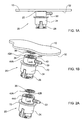
- FIG. 1A illustrating a top wall portion 10 of a fuel tank (not seen in whole) made of a thermoplastic material with a fuel accessory, namely roll-over valve generally designated 20 attached thereto at a wall site designated 22.
- fuel accessory which is in the form of a valve though, one should appreciate that the term fuel accessory should be understood in its broadest meaning, referring to, among others, different types of valves, liquid traps, gauges, filters etc., as well as carriers attached to the fuel tank and which in turn bear valve members etc.
- the fuel accessory 20 is a roll-over valve comprising a housing 24 made of a thermoplastic material and a snap-type closure member 28 retaining in place the valve's components.
- Fig. 1A no connecting means are required for attaching the valve to the fuel tank's wall portion 10, whereby the effective dead space, namely the space between maximum fuel level and the top wall of the tank is retained to a minimum and further whereby the outlet nozzle 30 extends right adjacent below the bottom surface 32 of the top wall 10 of the fuel tank.
- the effective dead space namely the space between maximum fuel level and the top wall of the tank is retained to a minimum
- the outlet nozzle 30 extends right adjacent below the bottom surface 32 of the top wall 10 of the fuel tank.
- no apertures are formed at the fuel tank's walls and thus fuel vapor is retained to a minimum.
- valve 20 is attached to the fuel tank's top wall 10 by fusion welding, facilitated by a coiled fusion melting element 36, which in the particular illustrated embodiments is accommodated within a corresponding coiled path 38 formed at a top engaging surface 40 of the valve 20.
- top engaging surface 40 has a contour corresponding with that of the wall site which, in the present case, is flat, so as to ensure adequate contact surface.
- the coiled fusion melting element 36 has two conductive leg members 42A and 42B, respectively, for applying to the coiled filament an electric current.
- the housing 24 of valve 20 is fitted at an upper portion thereof with grooves 44A and 44B, through which the conductive legs project, whereby the conductive leg portions may then be engaged by conductive wires or other conductive means as will be discussed hereinafter.
- the fusion melting element may also be received within a weldable carrying member, e.g. embedded within a disc-like member disposed between the housing of the fuel accessory and the wall site of the fuel tank, whereby heating the fusion melting element results in melting the carrying member to weld at both faces thereof and form the attachment.
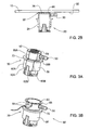
- a valve generally designated 50 wherein the fusion melting element 52 is in the form of an undulating filament received within a corresponding groove 54 formed at a top wall portion of the valve housing 56, with conductive leg portions 58A and 58B extending through corresponding grooves 60A and 60B formed along a portion of the housing 56 and extending to electric sockets 62A and 62B, respectively, for engagement with a current applicator, as will be explained hereinafter with reference to Fig. 6A .
- Fig. 3B is directed to a valve 50' similar to that disclosed in connection with Fig. 3A above, with the exception that the fusion melting element 63 is in the form of an open rink-like sheet of conductive material extending along foundries of the housing, and engageable with a current supply source via legs 64 projecting through a peripheral portion 65 of the housing. It is however appreciate that other shapes of a fusion melting element are possible also at sheet form.
- the housing ( 24 in Figs. 1 and 2A and 56 in Fig. 3 ) is fitted with a annular projecting shoulder 70, the purpose of which will become apparent hereinafter with reference to Fig. 6A and 6B .
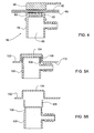
- Fig. 2B it can be seen how the valve 20 is welded at the wall site 22 of the bottom surface 32 of a top wall 10 of a fuel tank by fusion welding at 66.
- Fusion welding is carried out by applying an electric current through the fusion melting element, namely metal coil 36 to thereby heat the thermoplastic material to a temperature above its melting point whilst retaining the valve 20 against the surface 32 and allowing the molten material to cool down, whereby welding is obtained.
- Different parameters govern the fusion welding process, e.g. thickness and intensity of the filament of the fusion melting element, pattern and intensity of the coils or undulants, depth of accommodating groove within the respective element, type of plastic material, size of weldable portion, and the magnitude of the electric current applied through the fusion melting element.
- one or more fusion welding focuses may be applied, i.e. in case of a large carrier member, several welding sites may be performed.
- FIG. 4 there is illustrated an embodiment of fuel valve 76 in accordance with another embodiment, fitted at a top portion of the housing 78 with a coiled fusion melting element 80 and below there is provided a metallic member 82 (a disc in the represent example) embedded within the top portion of the housing 78.
- the arrangement is such that during the fusion welding process electric current to the fusion melting element 80 is excited by induction applied via an inductive coil member 86, generating also a magnetic force acting on the disc 82, so as to attract the entire housing 78 into tight engagement with the bottom surface 90 of the top wall portion 92 of the fuel tank.
- the disc 82 is not embedded within the housing 78 of the fuel accessory but is rather fitted within the space 96 of the valve and may then be removed after completing the fusion welding process.
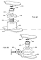
- Figs. 5A and 5B differs from the previous embodiments in the general configuration of the fuel accessory, i.e. valve 100, and further the top wall portion 102 of the fuel tank is formed with a protruding valve receiving formation 104 fitted for snugly receiving a top portion of the housing of valve 100, thereby making it unnecessary to support the valve during the welding process.
- the fuel accessory i.e. valve 100
- the top wall portion 102 of the fuel tank is formed with a protruding valve receiving formation 104 fitted for snugly receiving a top portion of the housing of valve 100, thereby making it unnecessary to support the valve during the welding process.
- the fusion melting element is a coiled filament 106 coaxially extending about the top portion 108 of the housing of the valve 100.
- the top portion 108 is formed with a corresponding coiled path (not shown) for receiving the fusion melting element 106.
- Figs. 5A and 5B ensures a minimal dead space between the bottom surface 110 of the top wall 102 of the fuel tank and the maximum fuel level within the valve 100.
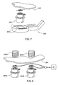
- Fig. 6A illustrates a process for fusion welding of a fuel accessory designated 140 to a bottom surface 142 of a top wall portion 144 of a fuel tank, using a manipulator 148.
- the fuel accessory 140 corresponds with the valve 20 of Figs. 1B and 2A and comprises a housing 148 formed with an annular shoulder 150 and a coiled path 154 receiving a coiled fusion melting element 156 with its conductive legs 158A and 158B laterally projecting through grooves 160A and 160B formed at a top portion of housing 148.
- valve 140 is placed within a receptacle 166 of a fuel accessory applicator 168 of manipulator 148.
- the manipulator arm is introduced through an opening formed in the fuel tank (typically a fuel pump aperture formed in the tank or any other suitable such opening) with the valve 140 received within the receptacle 166 with the annular shoulder 150 bearing against the top surface 170 of the applicator and whilst the conductive leg portions 158A and 158B engage electric sockets 172A and 172B of the manipulator 148, in turn connected by suitable conductive wires 176A and 176B, respectively, to a power supply 180.
- the fuel tank typically a fuel pump aperture formed in the tank or any other suitable such opening
- an electric current is applied through sockets 172A and 172B to conductive legs 158A and 158B, respectively, of the fusion melting element 156, whereby heat is generated at the coil, until the plastic material melts. Then, the current ceases to allow cooling down of the molten plastic material, whereby fusion welding is obtained.
- the manipulator 186 is similar to that seen in Fig. 6A with the exception that it is not used to apply an electric current, but rather to position the valve 188 at the appropriate wall site of the top wall 190 of the fuel tank and apply moderate pressure during the fusion welding process.
- the fusion melting element 194 is heated by a current applied thereto via induction, applied by an external induction coil 198.
- the manipulator 148 and 186 is removed after cooling down of the fusion welded zone.
- a fuel valve generally designated at 200, fitted with a fusion welding element 202, as disclosed according to any of the embodiments according to the invention.
- a piston assembly 210 is provided, wherein one end thereof 212 bears against a bottom wall 214 of the fuel tank and an upper retractable member thereof 216 is fitted with a valve receptacle 218 and appropriate current conducting means (not shown).
- the arrangement is such that the upper member 216 is spring biased by a coiled spring 220, so as to apply axial force to the valve 200, so that during the welding process it properly engages the inner wall surface 204 of the tank.
- the piston assembly may be operated by different means such as, for example, electromagnet, hydraulic, pneumatic, etc.
- valve 220 with the associated fusion welding element 222 are received within a receptacle 224 of a extendable 'scissors type' mechanism 228, wherein one leg portion has a support member 230 bearing against a bottom wall portion 232 of the fuel tank and whereby retracting the leg portions of the mechanism entails vertical displacement of the receptacle 224 for positioning the valve 220 flush against an inner wall surface 236 of the fuel tank, whilst applying suitable force, whereby applying an electric current to the fusion welding element entails fusion welding, as discussed hereinabove.
- Fig. 7 In order to ascertain that during the fusion welding process the fuel accessory, e.g. a valve 240, is properly and tightly engaged with a corresponding wall portion 242 of the fuel tank, there may be provided pressure indicators 246 e.g. in the form of strain gages or microswitches, which in the present embodiment are mounted on the end of the manipulating arm 250. Such pressure indicating means or sensors may however be mounted at other locations thereof.
- FIG. 8 exemplifies how two fuel accessories, namely valves 260A and 260B are simultaneously fitted to an inner wall surface 264 of a fuel tank.
- the arrangement is such that two inductive coil members 266A and 266B are positioned in register with the welding location of the corresponding valves 260A and 260B, and further there is provided a controller C for simultaneously applying current to the inductive coil members 266A and 266B and the valves 260A and 260B.
- this arrangement is suitable also for a large fuel accessory (rather then separate valves0, e.g. in the case of a carrier member attached to the fuel tank's inner wall, with respective fuel accessories attached in turn to said carrier.
- the fusion melting element may be integrated a priori within one of the fuel element or the wall site of the fuel tank or, it may be introduced into a suitable receptacle formed in either of the fuel accessory or wall site. In accordance with a different alternative, the fusion melting element is merely introduced between the fuel accessory and the wall site.
Landscapes
- Engineering & Computer Science (AREA)
- Mechanical Engineering (AREA)
- Life Sciences & Earth Sciences (AREA)
- Sustainable Development (AREA)
- Sustainable Energy (AREA)
- Chemical & Material Sciences (AREA)
- Combustion & Propulsion (AREA)
- Transportation (AREA)
- Cooling, Air Intake And Gas Exhaust, And Fuel Tank Arrangements In Propulsion Units (AREA)
- Lining Or Joining Of Plastics Or The Like (AREA)
Applications Claiming Priority (2)
| Application Number | Priority Date | Filing Date | Title |
|---|---|---|---|
| US10/760,718 US7389789B2 (en) | 2004-01-21 | 2004-01-21 | Fuel accessory for fuel tank and method for internally attaching same |
| PCT/IL2004/001076 WO2005070718A1 (en) | 2004-01-21 | 2004-11-24 | Fuel accessory for fuel tank and method for internally attaching same |
Publications (2)
| Publication Number | Publication Date |
|---|---|
| EP1708905A1 EP1708905A1 (en) | 2006-10-11 |
| EP1708905B1 true EP1708905B1 (en) | 2012-11-21 |
Family
ID=34750053
Family Applications (1)
| Application Number | Title | Priority Date | Filing Date |
|---|---|---|---|
| EP04799383A Expired - Lifetime EP1708905B1 (en) | 2004-01-21 | 2004-11-24 | Fuel accessory for fuel tank and method for internally attaching same |
Country Status (10)
| Country | Link |
|---|---|
| US (2) | US7389789B2 (enExample) |
| EP (1) | EP1708905B1 (enExample) |
| JP (1) | JP4939233B2 (enExample) |
| KR (1) | KR20070012642A (enExample) |
| CN (1) | CN100413722C (enExample) |
| BR (1) | BRPI0418417B1 (enExample) |
| CA (1) | CA2551958A1 (enExample) |
| MX (1) | MXPA06008112A (enExample) |
| RU (2) | RU96820U1 (enExample) |
| WO (1) | WO2005070718A1 (enExample) |
Families Citing this family (14)
| Publication number | Priority date | Publication date | Assignee | Title |
|---|---|---|---|---|
| FR2806959B1 (fr) * | 2000-04-03 | 2003-02-14 | Plastic Omnium Cie | Procede de fabrication d'un reservoir en matiere thermoplastique soufflee incorporant un insert |
| US7913712B2 (en) * | 2004-01-21 | 2011-03-29 | Raval A.C.S. Ltd. | Fuel accessory for fuel tank and method for internally attaching same |
| US7389789B2 (en) * | 2004-01-21 | 2008-06-24 | Raval-Agriculture Cooperative Societies Ltd. | Fuel accessory for fuel tank and method for internally attaching same |
| KR20090040432A (ko) * | 2006-07-12 | 2009-04-24 | 라발 에이.씨.에스. 엘티디 | 연료탱크용 벤팅배관 시스템 |
| KR100969388B1 (ko) * | 2008-08-14 | 2010-07-09 | 현대자동차주식회사 | 차량의 연료 공급 시스템 |
| DE102008059242A1 (de) * | 2008-11-21 | 2010-05-27 | Newfrey Llc, Newark | Fügeverfahren und -vorrichtung |
| DE102008059243A1 (de) | 2008-11-21 | 2010-05-27 | Newfrey Llc, Newark | Fügebauteil und Verfahren zum Herstellen eines Fügebauteils |
| JP5005711B2 (ja) * | 2009-01-22 | 2012-08-22 | 本田技研工業株式会社 | 燃料タンク用磁性部品の取り付け方法及び燃料タンク |
| FR2952142B1 (fr) * | 2009-10-29 | 2016-01-22 | Inergy Automotive Systems Res | Corps creux comportant un module accessoire fixe sur sa paroi, et module adapte pour un tel corps creux |
| JP5840264B2 (ja) * | 2014-07-24 | 2016-01-06 | 株式会社ミヤデン | 燃料タンクの熱溶着装置 |
| DE102015207835A1 (de) * | 2014-10-30 | 2016-05-04 | Volkswagen Aktiengesellschaft | Kraftstoffbehälter für ein Kraftfahrzeug |
| EP3516122B1 (de) | 2016-09-22 | 2024-09-04 | ARGO-HYTOS Group AG | Hydrauliktank und verfahren zur herstellung eines hydrauliktanks |
| KR101965430B1 (ko) * | 2017-07-17 | 2019-08-13 | (주)동희산업 | 플라스틱 연료탱크와 플라스틱 부품 결합용 열융착장치 및 이를 이용한 플라스틱 연료탱크와 플라스틱 부품의 결합방법 |
| KR102751291B1 (ko) * | 2019-10-23 | 2025-01-09 | 현대자동차주식회사 | 수소 충전 시스템 |
Family Cites Families (39)
| Publication number | Priority date | Publication date | Assignee | Title |
|---|---|---|---|---|
| US4108713A (en) * | 1977-02-14 | 1978-08-22 | General Binding Corporation | Low mass electric heater |
| US4455754A (en) * | 1980-05-22 | 1984-06-26 | Centro Corporation | Position sensing device |
| JPS5929397B2 (ja) * | 1980-08-15 | 1984-07-20 | 株式会社山武 | ダブルハンドを有するロボツト |
| DE3422074A1 (de) | 1984-06-14 | 1986-01-23 | Manfred 6000 Frankfurt Eck | Verfahren zur herstellung nicht loesbarer rohrverbindungen von kunststoffrohren |
| JPS61225027A (ja) * | 1985-03-30 | 1986-10-06 | Yamakawa Kogyo Kk | 合成樹脂製燃料タンクにおける別体部品の取付方法 |
| JPS63189228A (ja) * | 1987-02-02 | 1988-08-04 | Eidai Kako Kk | 各種接合部材の抵抗加熱接合方法 |
| JPH0618053Y2 (ja) | 1988-07-07 | 1994-05-11 | 日産自動車株式会社 | 燃料カットバルブ |
| US5169176A (en) * | 1989-02-10 | 1992-12-08 | Brossard Robert L | Heat shrinkable clamping, connecting, repair, and reinforcing sleeve and method of use |
| JPH0639698Y2 (ja) * | 1989-10-28 | 1994-10-19 | 利雄 近藤 | 障害者用箸 |
| JP3034992B2 (ja) * | 1991-06-14 | 2000-04-17 | 日産自動車株式会社 | 燃料タンクの燃料遮断装置 |
| WO1993022127A1 (en) | 1992-04-24 | 1993-11-11 | United Technologies Corporation | Bonding of thermoplastic and thermoset composite structures to metallic structures |
| US5404907A (en) | 1993-02-18 | 1995-04-11 | G. T. Products, Inc. | Weldable vapor vent valve for fuel tanks |
| JP2704253B2 (ja) | 1995-11-06 | 1998-01-26 | 東亜高級継手バルブ製造株式会社 | 熱可塑性樹脂製品の溶融着用発熱体 |
| JP3402946B2 (ja) * | 1996-07-30 | 2003-05-06 | ダイハツ工業株式会社 | フューエルタンクにおけるサブタンクの取付け構造 |
| US5968442A (en) * | 1996-08-08 | 1999-10-19 | Tohoku Munekata Co., Ltd. | Method for thermally connecting two molded products with a resistance heating element |
| JPH10220676A (ja) | 1997-02-04 | 1998-08-21 | Nkk Corp | 合成樹脂管用電気融着継手 |
| JPH10246382A (ja) | 1997-03-05 | 1998-09-14 | Nkk Corp | 合成樹脂管用電気融着継手 |
| JPH10246381A (ja) | 1997-03-05 | 1998-09-14 | Nkk Corp | 合成樹脂管用電気融着継手 |
| JP3394193B2 (ja) * | 1998-09-01 | 2003-04-07 | ジー・ピー・ダイキョー株式会社 | 熱可塑性樹脂成形品の接合方法 |
| JPH11254539A (ja) | 1998-03-10 | 1999-09-21 | Kubota Corp | 電気融着接合方法および装置 |
| US6035883A (en) | 1998-03-13 | 2000-03-14 | Eaton Corporation | Weldable vapor vent valve for fuel tanks |
| US6840274B1 (en) * | 1999-06-01 | 2005-01-11 | Stant Manufacturing Inc. | Weldable mount for fuel systems component |
| IL131051A0 (en) | 1999-07-23 | 2001-01-28 | Raviv Prec Injection Molding | Valve and method for fitting it to a tank |
| US6712234B2 (en) | 2000-02-14 | 2004-03-30 | Ti Group Automotive Systems Technology Center Gmbh | Fuel tank and method for its production |
| US6357101B1 (en) * | 2000-03-09 | 2002-03-19 | The Boeing Company | Method for installing fasteners in a workpiece |
| FR2807976B1 (fr) * | 2000-04-20 | 2002-06-28 | Plastic Omnium Cie | Reservoir a carburant de vehicule automobile |
| US6289915B1 (en) | 2000-06-06 | 2001-09-18 | Visteon Global Technologies, Inc. | Permeation and leak preventative design for fuel tank attachments |
| KR100521852B1 (ko) * | 2000-08-04 | 2005-10-14 | 프리아텍 악티엔게젤샤프트 | 가용성플라스틱으로 만들어진 구성요소를 연결시키는 장치 |
| BR0107075A (pt) | 2000-08-11 | 2002-07-16 | Visteon Global Tech Inc | Adaptador para soldar objetos a plástico |
| JP4345239B2 (ja) * | 2001-03-27 | 2009-10-14 | 豊田合成株式会社 | 燃料タンク |
| JP2002340101A (ja) * | 2001-05-15 | 2002-11-27 | Hakamada Beruto Kogyo Kk | ベルトコンベア用のベルト接合装置 |
| FR2831113B1 (fr) * | 2001-10-24 | 2004-01-02 | Inergy Automotive Systems Man | Systeme et procede d'obturation d'une ouverture d'un reservoir |
| US6742536B2 (en) * | 2001-11-13 | 2004-06-01 | Eaton Corporation | Attachment of fuel vapor vent valve to the inside of a fuel tank |
| US6727466B2 (en) * | 2001-12-18 | 2004-04-27 | Physical Systems, Inc. | Adhesive attachment assembly with heat source |
| JP2003191341A (ja) * | 2001-12-26 | 2003-07-08 | Munekata Kk | 熱可塑性樹脂成形品の熱溶着方法 |
| US6810913B2 (en) * | 2002-04-26 | 2004-11-02 | Visteon Global Technologies, Inc. | Internal fuel vapor valve |
| CA2510549C (en) * | 2002-12-23 | 2012-03-13 | Catalyst Services, Inc. | A cleaning and/or inspecting robot for hazardous environments including catalyst removal |
| US6863082B1 (en) * | 2003-08-13 | 2005-03-08 | Eaton Corporation | Mounting a fuel vapor management valve internally to a gas tank |
| US7389789B2 (en) * | 2004-01-21 | 2008-06-24 | Raval-Agriculture Cooperative Societies Ltd. | Fuel accessory for fuel tank and method for internally attaching same |
-
2004
- 2004-01-21 US US10/760,718 patent/US7389789B2/en not_active Expired - Lifetime
- 2004-11-24 RU RU2009142885/11U patent/RU96820U1/ru active
- 2004-11-24 WO PCT/IL2004/001076 patent/WO2005070718A1/en not_active Ceased
- 2004-11-24 JP JP2006550483A patent/JP4939233B2/ja not_active Expired - Fee Related
- 2004-11-24 CA CA002551958A patent/CA2551958A1/en not_active Abandoned
- 2004-11-24 EP EP04799383A patent/EP1708905B1/en not_active Expired - Lifetime
- 2004-11-24 KR KR1020067016793A patent/KR20070012642A/ko not_active Ceased
- 2004-11-24 BR BRPI0418417A patent/BRPI0418417B1/pt not_active IP Right Cessation
- 2004-11-24 MX MXPA06008112A patent/MXPA06008112A/es not_active Application Discontinuation
- 2004-11-24 RU RU2006129265/11A patent/RU2006129265A/ru unknown
- 2004-11-24 CN CNB2004800406359A patent/CN100413722C/zh not_active Expired - Lifetime
-
2008
- 2008-05-22 US US12/153,660 patent/US20080283196A1/en not_active Abandoned
Also Published As
| Publication number | Publication date |
|---|---|
| US20050155654A1 (en) | 2005-07-21 |
| EP1708905A1 (en) | 2006-10-11 |
| MXPA06008112A (es) | 2007-01-26 |
| BRPI0418417B1 (pt) | 2018-07-17 |
| RU2006129265A (ru) | 2008-02-27 |
| KR20070012642A (ko) | 2007-01-26 |
| CA2551958A1 (en) | 2005-08-04 |
| JP4939233B2 (ja) | 2012-05-23 |
| JP2007518627A (ja) | 2007-07-12 |
| US20080283196A1 (en) | 2008-11-20 |
| WO2005070718A1 (en) | 2005-08-04 |
| US7389789B2 (en) | 2008-06-24 |
| CN100413722C (zh) | 2008-08-27 |
| CN1906052A (zh) | 2007-01-31 |
| RU96820U1 (ru) | 2010-08-20 |
| BRPI0418417A (pt) | 2007-05-15 |
Similar Documents
| Publication | Publication Date | Title |
|---|---|---|
| US20080283196A1 (en) | Fuel accessory for fuel tank and method for internally attaching same | |
| US7385163B2 (en) | Fuel tank assembly and method of assembly | |
| JP2007518627A5 (enExample) | ||
| US7913712B2 (en) | Fuel accessory for fuel tank and method for internally attaching same | |
| CA2417954C (en) | Device for connecting components made of fusible plastic | |
| US9004453B2 (en) | Tapping fitting for a transport and storage container for liquids and transport and storage container with such tapping fitting | |
| EP2380765A2 (en) | Fuel system | |
| EP1179445A2 (en) | Plastic fuel tank having an arrangement for welding a component part in a fuel impermeable manner | |
| EP2008946B1 (en) | Container for liquids | |
| JP5207107B2 (ja) | 中空鋼板部品の溶接装置 | |
| JP4820469B2 (ja) | 溶接方法 | |
| US20140261745A1 (en) | Projection welded pressure relief valve assembly | |
| US20060290137A1 (en) | Threaded coupling for receptacles, such as expansion vessels, tanks and the like | |
| JP5348779B2 (ja) | 配管分岐部材の撤去方法及び装置 | |
| JP6359844B2 (ja) | 燃料タンクの部品溶着装置 | |
| JPH10169806A (ja) | 三方ロータリーバルブ及びこの弁を使用したlpガス充填方法 | |
| JP4478907B2 (ja) | 弁装置の製造方法 | |
| US11345094B1 (en) | Sidewall fusion method for fusing branch outlets to host plastic pipe and apparatus for use therein | |
| WO2011089482A1 (en) | Valve holder for expansion tanks | |
| JP2018069701A (ja) | 合成樹脂部品の取付方法 |
Legal Events
| Date | Code | Title | Description |
|---|---|---|---|
| PUAI | Public reference made under article 153(3) epc to a published international application that has entered the european phase |
Free format text: ORIGINAL CODE: 0009012 |
|
| 17P | Request for examination filed |
Effective date: 20060808 |
|
| AK | Designated contracting states |
Kind code of ref document: A1 Designated state(s): AT BE BG CH CY CZ DE DK EE ES FI FR GB GR HU IE IS IT LI LU MC NL PL PT RO SE SI SK TR |
|
| DAX | Request for extension of the european patent (deleted) | ||
| 17Q | First examination report despatched |
Effective date: 20070926 |
|
| GRAP | Despatch of communication of intention to grant a patent |
Free format text: ORIGINAL CODE: EPIDOSNIGR1 |
|
| RAP1 | Party data changed (applicant data changed or rights of an application transferred) |
Owner name: RAVAL A.C.S. LTD |
|
| RIN1 | Information on inventor provided before grant (corrected) |
Inventor name: VULKAN, OMER Inventor name: EHRMAN, MOSHE Inventor name: KLEINBERG, YEHOSHUA |
|
| GRAS | Grant fee paid |
Free format text: ORIGINAL CODE: EPIDOSNIGR3 |
|
| GRAA | (expected) grant |
Free format text: ORIGINAL CODE: 0009210 |
|
| AK | Designated contracting states |
Kind code of ref document: B1 Designated state(s): AT BE BG CH CY CZ DE DK EE ES FI FR GB GR HU IE IS IT LI LU MC NL PL PT RO SE SI SK TR |
|
| REG | Reference to a national code |
Ref country code: GB Ref legal event code: FG4D |
|
| REG | Reference to a national code |
Ref country code: CH Ref legal event code: EP |
|
| REG | Reference to a national code |
Ref country code: AT Ref legal event code: REF Ref document number: 584879 Country of ref document: AT Kind code of ref document: T Effective date: 20121215 |
|
| REG | Reference to a national code |
Ref country code: IE Ref legal event code: FG4D |
|
| REG | Reference to a national code |
Ref country code: DE Ref legal event code: R096 Ref document number: 602004040159 Country of ref document: DE Effective date: 20130117 |
|
| REG | Reference to a national code |
Ref country code: NL Ref legal event code: VDEP Effective date: 20121121 |
|
| REG | Reference to a national code |
Ref country code: AT Ref legal event code: MK05 Ref document number: 584879 Country of ref document: AT Kind code of ref document: T Effective date: 20121121 |
|
| PG25 | Lapsed in a contracting state [announced via postgrant information from national office to epo] |
Ref country code: FI Free format text: LAPSE BECAUSE OF FAILURE TO SUBMIT A TRANSLATION OF THE DESCRIPTION OR TO PAY THE FEE WITHIN THE PRESCRIBED TIME-LIMIT Effective date: 20121121 Ref country code: SE Free format text: LAPSE BECAUSE OF FAILURE TO SUBMIT A TRANSLATION OF THE DESCRIPTION OR TO PAY THE FEE WITHIN THE PRESCRIBED TIME-LIMIT Effective date: 20121121 Ref country code: ES Free format text: LAPSE BECAUSE OF FAILURE TO SUBMIT A TRANSLATION OF THE DESCRIPTION OR TO PAY THE FEE WITHIN THE PRESCRIBED TIME-LIMIT Effective date: 20130304 |
|
| PG25 | Lapsed in a contracting state [announced via postgrant information from national office to epo] |
Ref country code: SI Free format text: LAPSE BECAUSE OF FAILURE TO SUBMIT A TRANSLATION OF THE DESCRIPTION OR TO PAY THE FEE WITHIN THE PRESCRIBED TIME-LIMIT Effective date: 20121121 Ref country code: BE Free format text: LAPSE BECAUSE OF FAILURE TO SUBMIT A TRANSLATION OF THE DESCRIPTION OR TO PAY THE FEE WITHIN THE PRESCRIBED TIME-LIMIT Effective date: 20121121 Ref country code: PL Free format text: LAPSE BECAUSE OF FAILURE TO SUBMIT A TRANSLATION OF THE DESCRIPTION OR TO PAY THE FEE WITHIN THE PRESCRIBED TIME-LIMIT Effective date: 20121121 Ref country code: PT Free format text: LAPSE BECAUSE OF FAILURE TO SUBMIT A TRANSLATION OF THE DESCRIPTION OR TO PAY THE FEE WITHIN THE PRESCRIBED TIME-LIMIT Effective date: 20130321 Ref country code: GR Free format text: LAPSE BECAUSE OF FAILURE TO SUBMIT A TRANSLATION OF THE DESCRIPTION OR TO PAY THE FEE WITHIN THE PRESCRIBED TIME-LIMIT Effective date: 20130222 |
|
| PG25 | Lapsed in a contracting state [announced via postgrant information from national office to epo] |
Ref country code: AT Free format text: LAPSE BECAUSE OF FAILURE TO SUBMIT A TRANSLATION OF THE DESCRIPTION OR TO PAY THE FEE WITHIN THE PRESCRIBED TIME-LIMIT Effective date: 20121121 |
|
| REG | Reference to a national code |
Ref country code: CH Ref legal event code: PL |
|
| PG25 | Lapsed in a contracting state [announced via postgrant information from national office to epo] |
Ref country code: EE Free format text: LAPSE BECAUSE OF FAILURE TO SUBMIT A TRANSLATION OF THE DESCRIPTION OR TO PAY THE FEE WITHIN THE PRESCRIBED TIME-LIMIT Effective date: 20121121 Ref country code: SK Free format text: LAPSE BECAUSE OF FAILURE TO SUBMIT A TRANSLATION OF THE DESCRIPTION OR TO PAY THE FEE WITHIN THE PRESCRIBED TIME-LIMIT Effective date: 20121121 Ref country code: CH Free format text: LAPSE BECAUSE OF NON-PAYMENT OF DUE FEES Effective date: 20121130 Ref country code: DK Free format text: LAPSE BECAUSE OF FAILURE TO SUBMIT A TRANSLATION OF THE DESCRIPTION OR TO PAY THE FEE WITHIN THE PRESCRIBED TIME-LIMIT Effective date: 20121121 Ref country code: LI Free format text: LAPSE BECAUSE OF NON-PAYMENT OF DUE FEES Effective date: 20121130 Ref country code: BG Free format text: LAPSE BECAUSE OF FAILURE TO SUBMIT A TRANSLATION OF THE DESCRIPTION OR TO PAY THE FEE WITHIN THE PRESCRIBED TIME-LIMIT Effective date: 20130221 Ref country code: CZ Free format text: LAPSE BECAUSE OF FAILURE TO SUBMIT A TRANSLATION OF THE DESCRIPTION OR TO PAY THE FEE WITHIN THE PRESCRIBED TIME-LIMIT Effective date: 20121121 |
|
| REG | Reference to a national code |
Ref country code: IE Ref legal event code: MM4A |
|
| PG25 | Lapsed in a contracting state [announced via postgrant information from national office to epo] |
Ref country code: RO Free format text: LAPSE BECAUSE OF FAILURE TO SUBMIT A TRANSLATION OF THE DESCRIPTION OR TO PAY THE FEE WITHIN THE PRESCRIBED TIME-LIMIT Effective date: 20121121 Ref country code: IT Free format text: LAPSE BECAUSE OF FAILURE TO SUBMIT A TRANSLATION OF THE DESCRIPTION OR TO PAY THE FEE WITHIN THE PRESCRIBED TIME-LIMIT Effective date: 20121121 Ref country code: NL Free format text: LAPSE BECAUSE OF FAILURE TO SUBMIT A TRANSLATION OF THE DESCRIPTION OR TO PAY THE FEE WITHIN THE PRESCRIBED TIME-LIMIT Effective date: 20121121 |
|
| PLBE | No opposition filed within time limit |
Free format text: ORIGINAL CODE: 0009261 |
|
| STAA | Information on the status of an ep patent application or granted ep patent |
Free format text: STATUS: NO OPPOSITION FILED WITHIN TIME LIMIT |
|
| 26N | No opposition filed |
Effective date: 20130822 |
|
| PG25 | Lapsed in a contracting state [announced via postgrant information from national office to epo] |
Ref country code: IE Free format text: LAPSE BECAUSE OF NON-PAYMENT OF DUE FEES Effective date: 20121124 |
|
| REG | Reference to a national code |
Ref country code: DE Ref legal event code: R097 Ref document number: 602004040159 Country of ref document: DE Effective date: 20130822 |
|
| PG25 | Lapsed in a contracting state [announced via postgrant information from national office to epo] |
Ref country code: MC Free format text: LAPSE BECAUSE OF NON-PAYMENT OF DUE FEES Effective date: 20121130 Ref country code: TR Free format text: LAPSE BECAUSE OF FAILURE TO SUBMIT A TRANSLATION OF THE DESCRIPTION OR TO PAY THE FEE WITHIN THE PRESCRIBED TIME-LIMIT Effective date: 20121121 |
|
| PG25 | Lapsed in a contracting state [announced via postgrant information from national office to epo] |
Ref country code: LU Free format text: LAPSE BECAUSE OF NON-PAYMENT OF DUE FEES Effective date: 20121124 Ref country code: CY Free format text: LAPSE BECAUSE OF FAILURE TO SUBMIT A TRANSLATION OF THE DESCRIPTION OR TO PAY THE FEE WITHIN THE PRESCRIBED TIME-LIMIT Effective date: 20121121 |
|
| PG25 | Lapsed in a contracting state [announced via postgrant information from national office to epo] |
Ref country code: HU Free format text: LAPSE BECAUSE OF FAILURE TO SUBMIT A TRANSLATION OF THE DESCRIPTION OR TO PAY THE FEE WITHIN THE PRESCRIBED TIME-LIMIT Effective date: 20041124 |
|
| REG | Reference to a national code |
Ref country code: FR Ref legal event code: PLFP Year of fee payment: 12 |
|
| PG25 | Lapsed in a contracting state [announced via postgrant information from national office to epo] |
Ref country code: IS Free format text: LAPSE BECAUSE OF FAILURE TO SUBMIT A TRANSLATION OF THE DESCRIPTION OR TO PAY THE FEE WITHIN THE PRESCRIBED TIME-LIMIT Effective date: 20121121 |
|
| REG | Reference to a national code |
Ref country code: FR Ref legal event code: PLFP Year of fee payment: 13 |
|
| REG | Reference to a national code |
Ref country code: FR Ref legal event code: PLFP Year of fee payment: 14 |
|
| PGFP | Annual fee paid to national office [announced via postgrant information from national office to epo] |
Ref country code: FR Payment date: 20230929 Year of fee payment: 20 |
|
| PGFP | Annual fee paid to national office [announced via postgrant information from national office to epo] |
Ref country code: GB Payment date: 20231006 Year of fee payment: 20 |
|
| PGFP | Annual fee paid to national office [announced via postgrant information from national office to epo] |
Ref country code: DE Payment date: 20230926 Year of fee payment: 20 |
|
| REG | Reference to a national code |
Ref country code: DE Ref legal event code: R071 Ref document number: 602004040159 Country of ref document: DE |
|
| REG | Reference to a national code |
Ref country code: GB Ref legal event code: PE20 Expiry date: 20241123 |
|
| PG25 | Lapsed in a contracting state [announced via postgrant information from national office to epo] |
Ref country code: GB Free format text: LAPSE BECAUSE OF EXPIRATION OF PROTECTION Effective date: 20241123 |
|
| PG25 | Lapsed in a contracting state [announced via postgrant information from national office to epo] |
Ref country code: GB Free format text: LAPSE BECAUSE OF EXPIRATION OF PROTECTION Effective date: 20241123 |