EP1667308A2 - Procédé d'opération pour batterie secondaire et dispositif de batterie secondaire - Google Patents
Procédé d'opération pour batterie secondaire et dispositif de batterie secondaire Download PDFInfo
- Publication number
- EP1667308A2 EP1667308A2 EP06005336A EP06005336A EP1667308A2 EP 1667308 A2 EP1667308 A2 EP 1667308A2 EP 06005336 A EP06005336 A EP 06005336A EP 06005336 A EP06005336 A EP 06005336A EP 1667308 A2 EP1667308 A2 EP 1667308A2
- Authority
- EP
- European Patent Office
- Prior art keywords
- secondary battery
- charge
- battery
- temperature
- operation mode
- Prior art date
- Legal status (The legal status is an assumption and is not a legal conclusion. Google has not performed a legal analysis and makes no representation as to the accuracy of the status listed.)
- Granted
Links
Images


Classifications
-
- H—ELECTRICITY
- H02—GENERATION; CONVERSION OR DISTRIBUTION OF ELECTRIC POWER
- H02J—CIRCUIT ARRANGEMENTS OR SYSTEMS FOR SUPPLYING OR DISTRIBUTING ELECTRIC POWER; SYSTEMS FOR STORING ELECTRIC ENERGY
- H02J7/00—Circuit arrangements for charging or depolarising batteries or for supplying loads from batteries
- H02J7/007—Regulation of charging or discharging current or voltage
- H02J7/0071—Regulation of charging or discharging current or voltage with a programmable schedule
-
- B—PERFORMING OPERATIONS; TRANSPORTING
- B60—VEHICLES IN GENERAL
- B60L—PROPULSION OF ELECTRICALLY-PROPELLED VEHICLES; SUPPLYING ELECTRIC POWER FOR AUXILIARY EQUIPMENT OF ELECTRICALLY-PROPELLED VEHICLES; ELECTRODYNAMIC BRAKE SYSTEMS FOR VEHICLES IN GENERAL; MAGNETIC SUSPENSION OR LEVITATION FOR VEHICLES; MONITORING OPERATING VARIABLES OF ELECTRICALLY-PROPELLED VEHICLES; ELECTRIC SAFETY DEVICES FOR ELECTRICALLY-PROPELLED VEHICLES
- B60L3/00—Electric devices on electrically-propelled vehicles for safety purposes; Monitoring operating variables, e.g. speed, deceleration or energy consumption
- B60L3/0023—Detecting, eliminating, remedying or compensating for drive train abnormalities, e.g. failures within the drive train
- B60L3/0046—Detecting, eliminating, remedying or compensating for drive train abnormalities, e.g. failures within the drive train relating to electric energy storage systems, e.g. batteries or capacitors
-
- B—PERFORMING OPERATIONS; TRANSPORTING
- B60—VEHICLES IN GENERAL
- B60L—PROPULSION OF ELECTRICALLY-PROPELLED VEHICLES; SUPPLYING ELECTRIC POWER FOR AUXILIARY EQUIPMENT OF ELECTRICALLY-PROPELLED VEHICLES; ELECTRODYNAMIC BRAKE SYSTEMS FOR VEHICLES IN GENERAL; MAGNETIC SUSPENSION OR LEVITATION FOR VEHICLES; MONITORING OPERATING VARIABLES OF ELECTRICALLY-PROPELLED VEHICLES; ELECTRIC SAFETY DEVICES FOR ELECTRICALLY-PROPELLED VEHICLES
- B60L58/00—Methods or circuit arrangements for monitoring or controlling batteries or fuel cells, specially adapted for electric vehicles
- B60L58/10—Methods or circuit arrangements for monitoring or controlling batteries or fuel cells, specially adapted for electric vehicles for monitoring or controlling batteries
- B60L58/12—Methods or circuit arrangements for monitoring or controlling batteries or fuel cells, specially adapted for electric vehicles for monitoring or controlling batteries responding to state of charge [SoC]
- B60L58/13—Maintaining the SoC within a determined range
-
- B—PERFORMING OPERATIONS; TRANSPORTING
- B60—VEHICLES IN GENERAL
- B60L—PROPULSION OF ELECTRICALLY-PROPELLED VEHICLES; SUPPLYING ELECTRIC POWER FOR AUXILIARY EQUIPMENT OF ELECTRICALLY-PROPELLED VEHICLES; ELECTRODYNAMIC BRAKE SYSTEMS FOR VEHICLES IN GENERAL; MAGNETIC SUSPENSION OR LEVITATION FOR VEHICLES; MONITORING OPERATING VARIABLES OF ELECTRICALLY-PROPELLED VEHICLES; ELECTRIC SAFETY DEVICES FOR ELECTRICALLY-PROPELLED VEHICLES
- B60L58/00—Methods or circuit arrangements for monitoring or controlling batteries or fuel cells, specially adapted for electric vehicles
- B60L58/10—Methods or circuit arrangements for monitoring or controlling batteries or fuel cells, specially adapted for electric vehicles for monitoring or controlling batteries
- B60L58/16—Methods or circuit arrangements for monitoring or controlling batteries or fuel cells, specially adapted for electric vehicles for monitoring or controlling batteries responding to battery ageing, e.g. to the number of charging cycles or the state of health [SoH]
-
- B—PERFORMING OPERATIONS; TRANSPORTING
- B60—VEHICLES IN GENERAL
- B60L—PROPULSION OF ELECTRICALLY-PROPELLED VEHICLES; SUPPLYING ELECTRIC POWER FOR AUXILIARY EQUIPMENT OF ELECTRICALLY-PROPELLED VEHICLES; ELECTRODYNAMIC BRAKE SYSTEMS FOR VEHICLES IN GENERAL; MAGNETIC SUSPENSION OR LEVITATION FOR VEHICLES; MONITORING OPERATING VARIABLES OF ELECTRICALLY-PROPELLED VEHICLES; ELECTRIC SAFETY DEVICES FOR ELECTRICALLY-PROPELLED VEHICLES
- B60L58/00—Methods or circuit arrangements for monitoring or controlling batteries or fuel cells, specially adapted for electric vehicles
- B60L58/10—Methods or circuit arrangements for monitoring or controlling batteries or fuel cells, specially adapted for electric vehicles for monitoring or controlling batteries
- B60L58/24—Methods or circuit arrangements for monitoring or controlling batteries or fuel cells, specially adapted for electric vehicles for monitoring or controlling batteries for controlling the temperature of batteries
- B60L58/26—Methods or circuit arrangements for monitoring or controlling batteries or fuel cells, specially adapted for electric vehicles for monitoring or controlling batteries for controlling the temperature of batteries by cooling
-
- H—ELECTRICITY
- H02—GENERATION; CONVERSION OR DISTRIBUTION OF ELECTRIC POWER
- H02J—CIRCUIT ARRANGEMENTS OR SYSTEMS FOR SUPPLYING OR DISTRIBUTING ELECTRIC POWER; SYSTEMS FOR STORING ELECTRIC ENERGY
- H02J7/00—Circuit arrangements for charging or depolarising batteries or for supplying loads from batteries
- H02J7/0069—Charging or discharging for charge maintenance, battery initiation or rejuvenation
-
- H—ELECTRICITY
- H02—GENERATION; CONVERSION OR DISTRIBUTION OF ELECTRIC POWER
- H02J—CIRCUIT ARRANGEMENTS OR SYSTEMS FOR SUPPLYING OR DISTRIBUTING ELECTRIC POWER; SYSTEMS FOR STORING ELECTRIC ENERGY
- H02J7/00—Circuit arrangements for charging or depolarising batteries or for supplying loads from batteries
- H02J7/007—Regulation of charging or discharging current or voltage
- H02J7/00712—Regulation of charging or discharging current or voltage the cycle being controlled or terminated in response to electric parameters
- H02J7/007182—Regulation of charging or discharging current or voltage the cycle being controlled or terminated in response to electric parameters in response to battery voltage
-
- H—ELECTRICITY
- H02—GENERATION; CONVERSION OR DISTRIBUTION OF ELECTRIC POWER
- H02J—CIRCUIT ARRANGEMENTS OR SYSTEMS FOR SUPPLYING OR DISTRIBUTING ELECTRIC POWER; SYSTEMS FOR STORING ELECTRIC ENERGY
- H02J7/00—Circuit arrangements for charging or depolarising batteries or for supplying loads from batteries
- H02J7/007—Regulation of charging or discharging current or voltage
- H02J7/007188—Regulation of charging or discharging current or voltage the charge cycle being controlled or terminated in response to non-electric parameters
- H02J7/007192—Regulation of charging or discharging current or voltage the charge cycle being controlled or terminated in response to non-electric parameters in response to temperature
- H02J7/007194—Regulation of charging or discharging current or voltage the charge cycle being controlled or terminated in response to non-electric parameters in response to temperature of the battery
-
- Y—GENERAL TAGGING OF NEW TECHNOLOGICAL DEVELOPMENTS; GENERAL TAGGING OF CROSS-SECTIONAL TECHNOLOGIES SPANNING OVER SEVERAL SECTIONS OF THE IPC; TECHNICAL SUBJECTS COVERED BY FORMER USPC CROSS-REFERENCE ART COLLECTIONS [XRACs] AND DIGESTS
- Y02—TECHNOLOGIES OR APPLICATIONS FOR MITIGATION OR ADAPTATION AGAINST CLIMATE CHANGE
- Y02T—CLIMATE CHANGE MITIGATION TECHNOLOGIES RELATED TO TRANSPORTATION
- Y02T10/00—Road transport of goods or passengers
- Y02T10/60—Other road transportation technologies with climate change mitigation effect
- Y02T10/70—Energy storage systems for electromobility, e.g. batteries
Definitions
- the present invention relates to an operation method for a secondary battery that is repeatedly charged and discharged for use and a secondary battery device.
- a secondary battery device mounted on an electric vehicle prcvides energy for the vehicle to travel by charging a secondary battery with a charger to a predetermined charge end voltage and then discharging the battery as required.
- a temperature controller having a cooling fan or heater is typically provided in the secondary battery device.
- Charge control by the charger in such a secondary battery device is carried out in the following manner. That is, in the case of a lithium secondary battery, for example, constant current charge is first conducted with a constant current, constant voltage charge is then conducted for a predetermined time with a charge end voltage of, for example, 4.2 V, and thereby the secondary battery is charged to 100% of a quantity of charged electricity.
- a secondary battery device for storing a midnight electric power, for example.
- This secondary battery device comprises a secondary battery, a charger for charging the secondary battery with the midnight electric power, and an inverter for generating an alternating current power in the daytime from a DC power stored in the secondary battery.
- Charge control by the charger in such a secondary battery device for load-leveling is carried out in the following manner. That is, in the case of a lithium secondarybattery, for example, when the time period of the midnight electric power comes round, constant current charge is first conducted with a constant current, and upon attaining a predetermined voltage, the charge scheme is shifted to constant voltage charge, which is conducted for a predetermined time.
- Such a secondary battery has a disadvantage that raising the charge end voltage to enhance a charging rate promotes degradation of the battery, resulting in a reduced life thereof.
- This problem has been pointed out in Japanese Patent Laid-Open No. 11-4549, in which extension of the battery life is attempted by stopping charge before the secondary battery is fully charged to suppress the quantity of charged electricity.
- the battery life can be extended by suppressing the quantity of charged electricity as described in the above Japanese Patent Laid-Open No. 11-4549, however, the reduced quantity of charged electricity poses another problem of a reduced utilization factor of the secondary battery.
- the secondary battery cannot be fully used; for example, a driving range of the electric vehicle may be reduced.
- the required capacity of the secondary battery is predetermined in the design stage depending on a maximum power consumption by load, if the utilization factor of the secondary battery is reduced, the number of secondary batteries provided has to be increased accordingly, and therefore, the cost of equipment will be increased.
- a first object of this invention is to provide an operation method for a secondary battery and a secondary battery device that allow a user to decide which is to be given a priority, the life of the secondary battery or capacity thereof.
- a second object of this invention is to provide an operation method for a secondary battery and a secondary battery device that can provide an extended life of the secondary battery and an enhanced utilization factor thereof.
- At least two operation modes including first and second operation modes in which the secondary battery is charged to predetermined charge end voltages different from each other are established, and either of the two operationmodes can be selected according to a control signal from the outside of the secondary battery.
- an operation mode with high charge end voltage high battery capacity is provided, so that it is suitable for a case where a user wishes to travel a long distance by an electric vehicle, for example.
- an operation mode with low charge end voltage although the battery capacity is reduced, the life of the battery is extended, so that the running cost thereof is advantageously reduced. The user can select either of the modes arbitrarily.
- a secondarybattery device for load-leveling installed in an office building, for example, while power consumption by load is high on weekdays due to the operation of office automation appliances and an air conditioning system in the building, the power consumption by load is low on a holiday due to the significantly reduced rate of operation thereof. In this way, in a significant number of cases, the power consumption by load of the secondary battery device varies in a predetermined pattern. In such a secondary battery device, there should be no problem if the quantity of charged electricity of the secondary battery is suppressed before the load is reduced.
- a timer device switches the operation mode between the first operation mode and the second operation mode that are different in charge end voltage.
- the first and second operation modes may be switched to each other according to the battery temperature.
- the battery temperature is higher than a predetermined value, the battery is charged in the second operation mode with low charge end voltage. This is because when the battery temperature is high, the impedance of the battery is reduced and the quantity of charged electricity tends to increase, and the battery tends to be readily degraded, and therefore, it is desired that the life of the battery is extended by lowering the charge end voltage.
- the battery temperature may be measured with a temperature sensor attached to a battery case, or a temperature of the air surrounding the installed battery may be measured and regarded as the battery temperature.
- the first and second operation modes may be switched to each other according to a state of health (SOH) of the battery.
- SOH state of health
- the battery is charged in the second operation mode with low charge end voltage
- the state of health is equal to or lower than the predetermined value
- the battery is charged in the first operation mode with high charge end voltage.
- the state of health of the battery is high, the capacity of the battery is high and the internal resistance thereof is low, so that operation with low charge end voltage is possible, and thus, degradation of the battery is hard to advance.
- the state of health of the battery is reduced, increasing the charge end voltage enables an extended period of use of the battery.
- the state of health of the battery can be determined based on a voltage drop value and the battery temperature during discharge of the battery.
- the internal pressure of the battery may be measured, and the modes of the battery may be switched to each other according to the internal pressure.
- the internal pressure of the battery can be measured with a pressure sensor arranged in the battery, or a strain gage attached to a surface of the battery case.
- a battery temperature controlling device for controlling the battery temperature and the sensor for detecting the state of the battery are provided, and the battery is charged in the first operation mode with high charge end voltage, it is desired that the temperature of the secondary battery during charge and discharge is higher than that in the second operation mode. This is because the higher temperature allows the stored energy to be released more efficiently and a larger service capacity to be assured.
- a state of charge of the battery is high, it is desired that the operating temperature of the battery is low. This is because while the battery tends to readily be degraded when the state of charge of the battery is high, lowering the operating temperature enables the degradation to be suppressed.
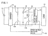
- Reference numeral 10 denotes a lithium secondary battery, which supplies a DC power to a load 11 composed of an inverter and the like for driving an electric vehicle.
- a charger 12 is connected to the secondary battery 10, and thus the secondary battery 10 can be charged with an alternating current power supplied from a commercial power supply 13.
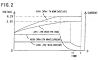
- An example of a charge pattern is shown in FIG. 2, in which upon beginning of charge, the battery is charged with a predetermined constant current to a predetermined charge end voltage, and then constant voltage charge with the charge end voltage is conducted until a predetermined time T, which is the total charge time, is reached.
- T which is the total charge time
- Reference numeral 14 denotes a temperature controller, which has a function of controlling an operating temperature of the secondary battery 10 based on a signal received from a temperature sensor 15 provided in the secondary battery 10.
- the temperature controller has a heater 16 and a cooling fan 17 attached to the secondary battery 10.
- the temperature controller closes a switch 16A to energize the heater 16, thereby heating the secondary battery 10, and when the temperature of the secondary battery 10 is higher than the predetermined reference temperature, it closes a switch 17A to drive the cooling fan 17, thereby cooling the secondary battery 10 with the outside air.
- Reference numeral 18 denotes operation mode setting means, which comprises a mode switch (not shown) provided on an instrument panel of the electric vehicle, for example, and can selectively switch between the high capacity mode and the long life mode by manipulating the switch.
- the high capacity mode corresponds to a "first operation mode” referred to herein
- the long life mode corresponds to a "second operation mode” referred to herein.
- the charger 12 When the operation mode setting means 18 sets either of the modes, a signal is transmitted to the charger 12 and the temperature controller 14 according to the mode.
- the charger 12 in the high capacity mode, the charger 12 has a charge current of 20A during the constant current charge and a charge end voltage of 4.2 V, and in the long life mode, it has a charge current of 10A during the constant current charge and a charge end voltage 3.9 V. That is, the charge end voltage is higher in the high capacity mode than in the long life mode, and the charge current during the constant current charge is larger in the high capacity mode than in the long life mode.
- an average operating temperature of the secondary battery 10 (during charge and discharge) controlled by the temperature controller 14 is set to fall within the range of 35°C ⁇ 20°C in the high capacity mode, and is set to fall within the range of 15°C ⁇ 20°C in the long life mode.
- the charge end voltage of the secondary battery 10 during charge is set at the higher value of 4.2 V, and the average temperature thereof during operation is set to fall within the range of 35°C ⁇ 20°C, so that a fresh battery is charged to a level of substantially 100% of a rated capacity thereof.
- the lithium secondary battery 10 having a capacity of 100Ah is used, the vehicle can travel about 150 km at the maximum.
- the charge end voltage of the secondary battery 10 during charge is set at the lower value of 3. 9 V, and the average temperature thereof during operation is set to fall within the range of 15°C ⁇ 20°C.
- a fresh battery is charged to a level of substantially 60% of a rated capacity thereof, and thus a maximum driving range results in about 90 km, which is shorter than that for the high capacity mode.
- the secondary battery 10 becomes less susceptible to degradation, the life of the battery becomes longer.
- the secondary battery 10 may be used in the long life mode on weekdays when the vehicle is used mainly in the neighborhood for shopping, commuting or the like, and may be used in the high capacity mode on a holiday when the vehicle is used for a long drive. In this way, the life of the secondary battery 10 can be extended while making the most of the power thereof as required.
- Operation Mode Charge Current Charge End Voltage Total Charge Time Operating Temperature High capacity mode 20A 4.2 V 8 hours 35°C ⁇ 20°C Long life mode 10A 3.9 V 8 hours 15°C ⁇ 20°C
- the secondary battery 10 was repeatedly charged and discharged. That is, the battery was discharged a number of times corresponding to five days of a week supposing the weekdays commuting (total driving range of about 40 km), and was discharged a number of times corresponding to remaining two days of a week supposing the holiday long drive (total driving range of 80 km).
- charge and discharge supposing weekdays were conducted in the long life mode in which the average operating temperature of the secondary battery 10 was 15°C
- charge and discharge supposing a holiday were conducted in the high capacity mode in which the average operating temperature of the secondary battery 10 was 35°C.
- charge and discharge were repeated in the same manner as the operation example 1 with the ratio of the long life mode to the high capacity mode being 5 to 2 (corresponding to an operation method as set forth in claim 1 of this invention).
- a "number of days of possible to drive” refers to a total number of operating days before the vehicle can no longer travel 40 km in a weekday or 80 km in a holiday.
- Number of Days of Possible to Drive Operation example 1 1197 days Operation example 2 763 days Comparison operation example 1 490 days Comparison operation example 2 637 days
- the number of days of possible to drive in the operation examples 1 and 2 in this embodiment are 1.6 to 2 times larger than those in the comparison operation examples 1 and 2 corresponding to the conventional operation method for the secondary battery, so that a long-life operation becomes possible.
- the number of days of possible to drive is smaller in the comparison operation example 1 using only the long life mode than in the comparison operation mode 2 using only the high capacity mode because a fresh battery is charged to a quantity of charged electricity enough for traveling only 90 km (60% of a rated capacity thereof), and thus the driving range of 80 km in a holiday cannot be covered if the battery is degraded.
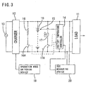
- FIG. 3 shows a second embodiment of this invention.
- a SOC measuring device 20 for measuring a state of charge of the secondary battery 10 is provided, and the temperature controller 14 is controlled by the SOC measuring device 20.
- the rest of the configuration is the same as the first embodiment, so that a same portion as in the first embodiment is assigned the same reference numeral and the description thereof is omitted.
- the state of charge (SOC) of the secondary battery 10 indicates a remaining capacity at that time.
- a state in which the battery is fully charged with the predetermined charge end voltage intended for attaining the rated capacity is defined as a SOC of 100%, and a state in which the battery then discharges electricity corresponding to a half of the rated capacity is defined as a SOC of 50%.
- the SOC is related with a no-load terminal voltage (open terminal voltage) of the secondary battery 10.
- the SOC measuring device 20 in this embodiment determines the SOC by obtaining the open circuit voltage at that time relying on a table or arithmetic equation of the open circuit voltage and the SOC created for the same kind of secondary battery, for example.
- the SOC is equal to or higher than 50%, for example, it outputs a signal to the temperature controller 14 for keeping the temperature of the secondary battery 10 relatively low (15°C ⁇ 20°C, for example), and if the SOC is lower than 50%, it outputs a signal to the temperature controller 14 for keeping the temperature of the secondary battery 10 higher (35°C ⁇ 20°C, for example).
- the charge end voltage of the secondary battery 10 during charge is set at the higher value of 4.2 V, so that a fresh battery is charged to a level of substantially 100% of a rated capacity thereof.
- the charge end voltage of the secondary battery 10 during charge is set at the lower value of 3.9 V, so that a fresh battery is charged to a level of substantially 60% of a rated capacity thereof, and thus a maximum driving range is shorter than that for the high capacity mode.
- the secondary battery 10 becomes less susceptible to degradation, the life of the battery becomes longer.
- the temperature of the secondary battery 10 is kept relatively low in the region of the SOC of 50% or higher where the battery is susceptible to degradation. Accordingly, degradation of the battery can be suppressed, and the life thereof can be extended.
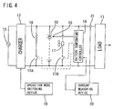
- FIG. 4 shows a third embodiment of this invention.
- a difference between the third and first embodiments is that a current measuring device 30 for measuring a discharge current from the secondary battery 10 is provided, and the temperature controller 14 is controlled by the current measuring device 30.
- the rest of the configuration is the same as the first embodiment, and a same portion as in the first embodiment is assigned the same reference numeral so that the description thereof is omitted.
- the discharge current from the secondary battery 10 is measured by a current sensor 31 provided in a discharge path leading to the load 11, and if the discharge current is equal to or lower than a predetermined value (20% of the rated current, for example), a signal is output to the temperature controller 14 for keeping the temperature of the secondary battery 10 relatively low (15°C ⁇ 20°C, for example), and if the discharge current is higher than 20%, a signal is output to the temperature controller 14 for keeping the temperature of the secondary battery 10 higher (35°C ⁇ 20°C, for example).
- the high capacity mode and the long life mode can be switched to one another by the mode switch in the operation mode setting means 18.
- the temperature of the secondary battery 10 is kept relatively low if the current during discharge is low, degradation of the battery can be suppressed.
- the temperature of the secondary battery 10 is kept relatively high if a large discharge current flows, stored energy can be efficiently released in the form of electric energy, and thus a certain service capacity can be assured.
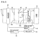
- FIGS. 5 and 6 a fourth embodiment of this invention applied to a secondary battery for storing midnight electric power in an office building will be described with reference to FIGS. 5 and 6.
- Reference numeral 40 denotes a lithium secondarybattery, which supplies a DC power to a load 41 composed of an inverter and the like connected to an electric power supply line in theofficebuilding.
- a charger 42 is connected to the secondary battery 40, and thus the secondary battery 40 can be charged with the commercial power supply during the time period of the midnight electric power according to a signal from a time measuring device 44.
- the charge pattern is the same as that shown in FIG. 2, for example, in which upon beginning of charge, the battery is charged with a predetermined constant current to a predetermined charge end voltage, and then constant voltage charge with the charge end voltage is conducted until a predetermined time T, which is the total charge time, is reached.
- Reference numeral 14 denotes a temperature controller having a function of controlling an operating temperature of the secondary battery 40 based on a signal received from a temperature sensor 15. Since it has the same configuration as that in the first embodiment, a same portion as in the first embodiment is assigned the same reference numeral and the description thereof is omitted.
- Reference numeral 45 denotes operationmode setting means, which can transmit a signal to the charger 42 to switch the operation mode thereof between the high capacity mode and the long life mode.
- the charger 42 in the high capacity mode, has a charge current of 20A during the constant current charge and a charge end voltage of 4.2 V, and in the longlifemode, ithas a charge current of 10A during the constant current charge and a charge end voltage 3.9 V. That is, the charge end voltage is higher in the high capacity mode than in the long life mode, and the charge current during the constant current charge is larger in the high capacity mode than in the long life mode.
- the operation mode setting means 45 transmits a signal also to the temperature controller 14, an average operating temperature of the secondary battery 40 (during charge and discharge) controlled by the temperature controller 14 is set to fall within the range of 35°C ⁇ 20°C in the high capacity mode, and is set to fall within the range of 15°C ⁇ 20°C in the long life mode.
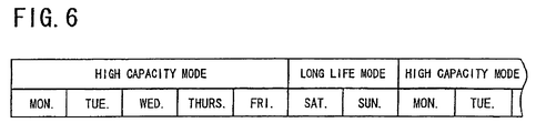
- the timing of switching the operation mode in the operation mode setting means 45 is controlled by a timer device 46.
- the timer device 46 obtains time information from the time measuring device 44 and follows a schedule previously established and stored therein. For example, as shown in FIG. 6, the long life mode is adopted from Friday midnight to Sunday evening, and the high capacity mode is adopted during the rest time period (from Sunday midnight to Friday evening).
- the charger 42 charges the secondary battery 40 in the high capacity mode (with the charge end voltage of 4.2 V) on weekdays, and is controlled by the temperature controller 14 to attain the average temperature falling within the range of 35°C ⁇ 20°C during operation.
- a fresh battery is charged to a level of substantially 100% of a rated capacity thereof, and when the lithium secondary, battery 40 having a capacity of 100Ah is used, electric power for about six hours during the daytime on weekdays in a typical office building can be supplied.
- the long life mode is automatically set during the period from Friday midnight to Sunday evening.
- the charge end voltage of the secondary battery 40 during charge is set at the lower value of 3.9 V, and the average temperature thereof during operation is set to fall within the range of 15°C ⁇ 20°C. Accordingly, a fresh secondary battery 40 is charged to a level of substantially 60% of a rated capacity thereof, and thus degradation of the secondary battery 40 is suppressed.
- electric power consumption of the office building is reduced on a holiday, electric power for about six hours on a holiday can be supplied, so that there is no problem practically.
- Operation Mode Charge Current Charge End Voltage Total Charge Time Operating Temperature High capacity mode 20A 4.2 V 8 hours 35°C ⁇ 20°C Long life mode 10A 3.9 V 8 hours 15°C ⁇ 20°C
- the secondary battery 40 was repeatedly charged and discharged. That is, the battery discharged electricity corresponding to the weekdays electric power consumption (50Ah) a number of times corresponding to five days in a week, and discharged electricity corresponding to the holiday electric power consumption (25Ah) a number of times corresponding to remaining two days in a week.
- the high capacity mode was adopted on weekdays in which the quantity of charged electricity of the secondary battery 40 is 100% of a rated capacity thereof (100Ah) if the battery is fresh and the average operating temperature thereof is 35°C, and the long life mode was adopted on a holiday in which the quantity of charged electricity of the secondary battery 40 is 60% of a rated capacity thereof (60Ah) if the battery is fresh and the average operating temperature thereof being 15°C.
- a "number of days of power available” refers to a total number of days of power available before discharge of 50Ah becomes impossible on a weekday, or discharge of 25Ah becomes impossible on a holiday.
- the number of days of power available of the secondary battery 40 in the operation example 3 is 2 or more times larger than that in the comparison operation examples 3 and 4 corresponding to the conventional operation method for the secondary battery, so that a long-life operation becomes possible.
- FIG. 7 shows a fifth embodiment of this invention.
- a difference between the fifth and fourth embodiments is that a SOC measuring device 50 is added thereto, and the temperature controller 14 is controlled by the SOC measuring device 50 rather than the operation mode setting means 45.
- the rest of the configuration is the same as the fourth embodiment, so that a same portion as in the fourth embodiment is assigned the same reference numeral and the description thereof is omitted.
- the SOC measuring device 50 determines the state of charge based on the open circuit voltage of the secondary battery 40. If the SOC is equal to or higher than 50%, for example, it outputs a signal to the temperature controller 14 for keeping the temperature of the secondary battery 40 relatively low (15°C ⁇ 20°C, for example), and if the SOC is lower than 50%, it outputs a signal to the temperature controller 14 for keeping the temperature of the secondary battery 40 higher (35°C ⁇ 20°C, for example).
- the charger 42 charges the secondary battery 40 in the high capacity mode with the charge end voltage of 4.2 V on weekdays, so that a fresh battery is charged to a level of substantially 100% of a rated capacity thereof. Furthermore, the long life mode is automatically set during the period from Friday midnight to Sunday evening. In this case, the charge end voltage of the.secondary battery 40 during charge is set at the lower value of 3. 9 V, so that a fresh secondary battery 40 is charged to a level of substantially 60% of a rated capacity thereof, and thus degradation of the secondary battery 40 is suppressed.
- the temperature of the secondary battery 40 is kept relatively low (15°C ⁇ 20°C) in the region of the state of charge of 50% or higher where the battery is susceptible to degradation. Accordingly, degradation of the battery can be suppressed, and the life thereof can be extended further.
- FIG. 8 shows a sixth embodiment of this invention.
- the SOC measuring device 50 is replaced with a current measuring device 60 for measuring a discharge current from the secondary battery 40, and the temperature controller 14 is controlled by the current measuring device 60.
- the rest of the configuration is the same as the fifth embodiment, and a same portion as in the fifth embodiment is assigned the same reference numeral so that the description thereof is omitted.
- the discharge current from the secondary battery 40 is measured by a current sensor 61 provided in a discharge path leading to the load 41, and if the discharge current is equal to or lower than a predetermined value (20% of the rated current, for example), a signal is output to the temperature controller 14 for keeping the temperature of the secondary battery 40 relatively low (15°C ⁇ 20°C, for example), and if the discharge current is higher than 20%, a signal is output to the temperature controller 14 for keeping the temperature of the secondary battery 40 higher (35°C ⁇ 20°C, for example).
- the charger 42 charges the secondary battery 40 in the high capacity mode on weekdays, and in the long life mode from Friday midnight to Sunday evening.
- the temperature of the secondary battery 40 is kept relatively low if the current during discharge is low, degradation of the battery can be suppressed.
- the temperature of the secondary battery 40 is kept relatively high if a large discharge current flows, stored energy can be efficiently released in the form of electric energy, and thus a certain service capacity can be assured.
- FIG. 9 shows a seventh embodiment of this invention.
- Reference numeral 70 denotes a lithiumsecondary battery, which supplies a DC power to a load 71 composed of an inverter and the like for driving an electric vehicle.
- a charger 72 is connected to the secondary battery 70, and thus the secondary battery 70 can be charged with an alternating current power supplied from a commercial power supply 73.
- the charge pattern is arranged so that upon beginning of charge, the battery is charged with a predetermined constant current to a predetermined charge end voltage, and then constant voltage charge with the charge end voltage is conducted until a predetermined time T, which is the total charge time, is reached.
- T which is the total charge time
- operation modes are switched to each other according to a signal received from operation mode setting means 74.
- the charge end voltage is set at 4.2 V
- the charge end voltage is set at 3.85 V
- an intermediate mode as a third operation mode, in which the charge end voltage is set at 3.95 V, for example.
- a temperature sensor 75 is provided near the secondary battery 70, and by means of a signal from the sensor, the temperature measuring device 76 measures the temperature of the secondary battery 70 and transmits a signal associated with the temperature to the operation mode setting means 74.
- the operationmode settingmeans 74 comprises a storage circuit storing a table of the temperature and the modes associated with each other as shown below, and determines the operation mode according to the temperature. Temperature of Secondary Battery 70 Operation Mode Charge End Voltage -20°C - 10°C Intermediate mode 3.95 V 10°C - 35°C High capacity mode 4.20 V Higher than 35°C Long life mode 3.85 V
- FIG. 10 shows an eighth embodiment of this invention.
- Referencenumeral 80 denotes alithiumsecondarybattery having a capacity of 100Ah, for example, which supplies a DC power to a load 81 composed of an inverter and the like for driving an electric vehicle.
- a charger 82 is connected to the secondary battery 80, and thus the secondary battery 80 can be charged with an alternating current power supplied from a commercial power supply 83.
- the charge pattern is arranged so that upon beginning of charge, the battery is charged with a predetermined constant current to a predetermined charge end voltage, and then constant voltage charge with the charge end voltage is conducted until a predetermined time T, which is the total charge time, is reached.
- T which is the total charge time
- operation modes are switched to each other according to a signal received from operation mode setting means 84.
- the charge end voltage is set at 4.2 V
- the charge end voltage is set at 3.9 V.
- Reference numeral 85 denotes a SOH measuring device for measuring a SOH (State of Health) of the secondary battery 80.
- SOH State of Health
- SOH State of Health
- an internal resistance thereof is increased, so that the state of health of the battery can be determined from a table of a voltage drop value when the battery is discharged and a temperature of the battery.
- An example of the table of the state of health used in this embodiment is shown below, and the table is stored in the storage in the SOH measuring device 85.
- the voltage drop value indicates a value (in the unit V) attained after the secondary battery 80 is discharged at the level of 100A for three minutes
- the SOH of 100% refers to a state in which the secondary battery 80 is a fresh one and has a rated capacity thereof
- the SOH of 0% refers to a state in which the secondary battery 80 is degraded and the service capacity thereof is reduced to the lowest level required for the load.
- Temperature (°C) SOH (%) 100 75 50 25 0 -10 0.91 1.43 1.88 2.29 2.73 0 0.46 0.72 0.97 1.21 1.38 10 0.27 0.39 0.58 0.74 0.81 20 0.22 0.33 0.47 0.59 0.66 30 0.17 0.26 0.35 0.43 0.51
- the SOH measuring device 85 detects the temperature of the secondary battery 80 according to the signal from the temperature sensor 85, detects the voltage drop value by performing a discharge test on the secondary battery 80, and determines the SOH according to the above table using these values. Then, the SOH measuring device transmits a signal to the operation mode setting means 84 to let the charger 82 operate in the long life mode until the SOH is reduced to 25%, for example, and to let the charger 82 operate in the high capacity mode when the SOH is equal to or lower than 25%.
- the advance of the degradation can be suppressed to the utmost.
- charge is conducted in the high capacity mode, that maximizes the capability of the battery which capacity is degrading.
- the temperature controller 14 may be provided as in the first embodiment to keep the temperature of the secondary battery 80 low in the long life mode and high in the high capacity mode.
- the SOC measuring device 2C may be provided as in the second embodiment to keep the temperature of the secondary battery 80 low when the SOC is high and high when the SOC is low.
- the current measuring device 30 may be provided as in the third embodiment to keep the operating temperature low when the discharge current is low and high when the discharge current is high.
- FIG. 11 shows a ninth embodiment of this invention.
- Reference numeral 90 denotes a lithiumsecondarybattery, which supplies a DC power to a load 91 composed of an inverter and the like for driving an electric vehicle.
- a charger 92 is connected to the secondary battery 90, and thus the secondary battery 90 can be charged with an alternating current power supplied from a commercial power supply 93.
- the charge pattern is arranged so that upon beginning of charge, the battery is charged with a predetermined constant current to a predetermined charge end voltage, and then constant voltage charge with the charge end voltage is conducted until a predetermined time T, which is the total charge time, is reached.
- T which is the total charge time
- These operation modes are switched to each other according to a signal received from an operation mode setting means 94.
- the charge end voltage is set at 4.2 V
- the charge end voltage is set at 3.9 V.
- Reference numeral 95 denotes a pressure measuring device for measuring an internal pressure of the secondary battery 90.
- the internal pressure is detected with a pressure sensor 96 attached to a battery case (not shown) in this embodiment, it may also be detected with a strain gage attached to a surface of the battery case.
- the internal pressure of the secondary battery 90 was 0.1 MPa when the battery was fresh, 0.2 MPa when the state of health was on the order of 50%, 0.25 MPa when the state of health was 25%, and 0.3 MPa at the end of the life thereof.
- the pressure measuring device 95 detects the internal pressure of the secondary battery 90 according to a signal from the pressure sensor 96, and transmits a signal to the operation mode setting means 94 to let the charger 92 operate in the long life mode until the pressure reaches 0.25 MPa, for example, and to let the charger 92 operate in the high capacity mode when the pressure is equal to or higher than 0.25 MPa.
- the advance of the degradation can be suppressed to the utmost.
- charge is conducted in the high capacity mode, that maximizes the capability of the battery which capacity is degrading.
- the temperature controller 14 maybe provided as in the first embodiment to keep the temperature of the secondary battery 90 low in the long life mode and high in the high capacity mode.
- the SOC measuring device 20 may be provided as in the second embodiment to keep the temperature of the secondary battery 90 low when the SOC is high and high when the SOC is low.
- the current measuring device 30 may be provided as in the third embodiment to keep the operating temperature low when the discharge current is low and high when the discharge current is high.
Priority Applications (1)
| Application Number | Priority Date | Filing Date | Title |
|---|---|---|---|
| EP10010207A EP2278682A1 (fr) | 2001-03-28 | 2002-03-28 | Dispositif de batterie secondaire |
Applications Claiming Priority (3)
| Application Number | Priority Date | Filing Date | Title |
|---|---|---|---|
| JP2001091921 | 2001-03-28 | ||
| JP2002050012A JP4019734B2 (ja) | 2001-03-28 | 2002-02-26 | 二次電池の運用方法及び二次電池装置 |
| EP02007176A EP1246336A3 (fr) | 2001-03-28 | 2002-03-28 | Procédé d'opération pour batterie secondaire et dispositif de batterie secondaire |
Related Parent Applications (2)
| Application Number | Title | Priority Date | Filing Date |
|---|---|---|---|
| EP02007176A Division EP1246336A3 (fr) | 2001-03-28 | 2002-03-28 | Procédé d'opération pour batterie secondaire et dispositif de batterie secondaire |
| EP02007176.7 Division | 2002-03-28 |
Related Child Applications (1)
| Application Number | Title | Priority Date | Filing Date |
|---|---|---|---|
| EP10010207.8 Division-Into | 2010-09-22 |
Publications (3)
| Publication Number | Publication Date |
|---|---|
| EP1667308A2 true EP1667308A2 (fr) | 2006-06-07 |
| EP1667308A3 EP1667308A3 (fr) | 2009-12-09 |
| EP1667308B1 EP1667308B1 (fr) | 2013-05-22 |
Family
ID=26612298
Family Applications (3)
| Application Number | Title | Priority Date | Filing Date |
|---|---|---|---|
| EP06005336.0A Expired - Fee Related EP1667308B1 (fr) | 2001-03-28 | 2002-03-28 | Dispositif de batterie secondaire |
| EP10010207A Withdrawn EP2278682A1 (fr) | 2001-03-28 | 2002-03-28 | Dispositif de batterie secondaire |
| EP02007176A Withdrawn EP1246336A3 (fr) | 2001-03-28 | 2002-03-28 | Procédé d'opération pour batterie secondaire et dispositif de batterie secondaire |
Family Applications After (2)
| Application Number | Title | Priority Date | Filing Date |
|---|---|---|---|
| EP10010207A Withdrawn EP2278682A1 (fr) | 2001-03-28 | 2002-03-28 | Dispositif de batterie secondaire |
| EP02007176A Withdrawn EP1246336A3 (fr) | 2001-03-28 | 2002-03-28 | Procédé d'opération pour batterie secondaire et dispositif de batterie secondaire |
Country Status (3)
| Country | Link |
|---|---|
| US (1) | US6674265B2 (fr) |
| EP (3) | EP1667308B1 (fr) |
| JP (1) | JP4019734B2 (fr) |
Cited By (5)
| Publication number | Priority date | Publication date | Assignee | Title |
|---|---|---|---|---|
| WO2011011755A3 (fr) * | 2009-07-23 | 2011-05-05 | Qualcomm Incorporated | Charge de batterie servant à prolonger l'autonomie de la batterie et améliorer son rendement |
| WO2011063053A3 (fr) * | 2009-11-17 | 2011-07-14 | Qualcomm Incorporated | Gestion d'énergie pour dispositifs électroniques |
| CN101625398B (zh) * | 2009-08-03 | 2012-06-27 | 奇瑞汽车股份有限公司 | 一种纯电动车电池寿命计算及报警装置的控制方法 |
| US8853995B2 (en) | 2009-06-12 | 2014-10-07 | Qualcomm Incorporated | Devices for conveying wireless power and methods of operation thereof |
| CN110596603A (zh) * | 2019-09-24 | 2019-12-20 | 东软睿驰汽车技术(沈阳)有限公司 | 一种电池信息的生成方法和装置 |
Families Citing this family (90)
| Publication number | Priority date | Publication date | Assignee | Title |
|---|---|---|---|---|
| JP3839382B2 (ja) * | 2002-09-13 | 2006-11-01 | 本田技研工業株式会社 | 車載蓄電装置の制御装置 |
| JP2004159382A (ja) * | 2002-11-01 | 2004-06-03 | Toshiba Corp | 電子機器 |
| JP3933096B2 (ja) * | 2003-06-03 | 2007-06-20 | トヨタ自動車株式会社 | 車両に搭載されたバッテリ制御装置および制御方法 |
| JP2005025382A (ja) * | 2003-06-30 | 2005-01-27 | Toshiba Corp | 電子機器および電源制御方法 |
| US6868318B1 (en) * | 2003-10-14 | 2005-03-15 | General Motors Corporation | Method for adjusting battery power limits in a hybrid electric vehicle to provide consistent launch characteristics |
| JP4093205B2 (ja) * | 2003-12-05 | 2008-06-04 | 松下電器産業株式会社 | 充電制御装置 |
| US20050156577A1 (en) * | 2004-01-21 | 2005-07-21 | Henry Sully | Method for charge control for extending Li-Ion battery life |
| US7248023B2 (en) | 2004-04-22 | 2007-07-24 | Matsushita Electric Industrial Co., Ltd. | Charger for lithium secondary battery and electronic apparatus including charger |
| US7667942B2 (en) * | 2004-12-13 | 2010-02-23 | Schlumberger Technology Corporation | Battery switch for downhole tools |
| KR100842678B1 (ko) * | 2005-03-17 | 2008-06-30 | 주식회사 엘지화학 | 동적 패턴에 대한 배터리 잔존량 추정법의 비교 참조값구성 방법 |
| JP4372074B2 (ja) * | 2005-09-27 | 2009-11-25 | 三洋電機株式会社 | 二次電池の充電方法 |
| US7730984B2 (en) * | 2006-06-07 | 2010-06-08 | Gm Global Technology Operations, Inc. | Method and apparatus for control of a hybrid electric vehicle to achieve a target life objective for an energy storage device |
| JP4967601B2 (ja) | 2006-10-31 | 2012-07-04 | ソニー株式会社 | 電子機器、電子機器の充電方法 |
| JP5268330B2 (ja) * | 2006-12-04 | 2013-08-21 | パナソニック株式会社 | 充電システム、充電装置、及び電池パック |
| JP4990612B2 (ja) * | 2006-12-27 | 2012-08-01 | パナソニック株式会社 | 充電制御装置、携帯端末装置、および充電制御方法 |
| CN101232110B (zh) * | 2007-01-25 | 2010-05-26 | 华为技术有限公司 | 电池充电方法和装置 |
| WO2008092343A1 (fr) * | 2007-01-25 | 2008-08-07 | Huawei Technologies Co., Ltd. | Procédé et dispositif de charge de pile |
| JP2008253129A (ja) * | 2007-03-07 | 2008-10-16 | Matsushita Electric Ind Co Ltd | リチウム系二次電池の急速充電方法およびそれを用いる電子機器 |
| AU2012201155B2 (en) * | 2007-05-10 | 2016-10-20 | Auckland Uniservices Limited | Multi power sourced electric vehicle |
| US9466419B2 (en) | 2007-05-10 | 2016-10-11 | Auckland Uniservices Limited | Apparatus and system for charging a battery |
| FR2916099B1 (fr) * | 2007-05-11 | 2009-07-31 | Commissariat Energie Atomique | Procede de charge d'une batterie d'un systeme autonome |
| WO2008149621A1 (fr) * | 2007-06-01 | 2008-12-11 | Ishida Co., Ltd. | Système à fiche de casier électronique |
| US8307967B2 (en) * | 2007-07-04 | 2012-11-13 | Satyajit Patwardhan | Widely deployable charging system for vehicles |
| US7782021B2 (en) * | 2007-07-18 | 2010-08-24 | Tesla Motors, Inc. | Battery charging based on cost and life |
| JP2009059504A (ja) * | 2007-08-30 | 2009-03-19 | Sony Corp | 電池パックおよび制御方法 |
| JP2009124795A (ja) * | 2007-11-12 | 2009-06-04 | Sony Corp | 充電方法および装置 |
| US8258751B2 (en) * | 2007-11-15 | 2012-09-04 | Broadcom Corporation | Method and system for tracking battery state-of-health based on charging information |
| JP4539735B2 (ja) * | 2008-02-29 | 2010-09-08 | 三菱自動車工業株式会社 | バッテリ管理制御装置 |
| JP4715881B2 (ja) * | 2008-07-25 | 2011-07-06 | トヨタ自動車株式会社 | 電源システムおよびそれを備えた車両 |
| GB2462467B (en) * | 2008-08-08 | 2013-03-13 | P G Drives Technology Ltd | A cell management system |
| EP2209177B8 (fr) | 2009-01-16 | 2019-03-20 | Tesla, Inc. | Système et procédé de chargement multimodal pour véhicule électrique |
| EP2394329B1 (fr) * | 2009-02-09 | 2015-09-30 | Younicos, Inc. | Décharge de batteries |
| US9496722B2 (en) | 2009-08-05 | 2016-11-15 | Gs Yuasa International Ltd. | Battery system including bypass electrical path and heater bypass electrical path that connects a portion of bypass electrical path upstream relative to a heater to a portion of bypass electrical path downstream relative to the heater |
| US8820446B2 (en) * | 2009-11-17 | 2014-09-02 | Toyota Jidosha Kabushiki Kaisha | Vehicle and method for controlling vehicle |
| JP4837084B2 (ja) * | 2009-11-30 | 2011-12-14 | 株式会社東芝 | 電子機器 |
| JP5512250B2 (ja) * | 2009-12-09 | 2014-06-04 | 三洋電機株式会社 | パック電池 |
| TWI411796B (zh) * | 2009-12-22 | 2013-10-11 | Ind Tech Res Inst | 電池循環壽命估測裝置 |
| EP2524829B1 (fr) * | 2010-01-15 | 2017-09-13 | Mitsubishi Heavy Industries, Ltd. | Système de climatisation pour véhicule et procédé de commande d'entraînement associé |
| US8564246B2 (en) * | 2010-03-30 | 2013-10-22 | Grrreen, Inc. | Battery charging system and method |
| US9007025B2 (en) | 2010-04-07 | 2015-04-14 | Dell Products, L.P. | Systems and methods for configuring and charging hybrid battery systems |
| US8471520B2 (en) | 2010-05-04 | 2013-06-25 | Xtreme Power Inc. | Managing renewable power generation |
| KR101132948B1 (ko) * | 2010-05-13 | 2012-04-05 | 엘에스산전 주식회사 | 전기자동차 충방전 시스템, 충방전 장치, 충방전 방법 |
| WO2011145250A1 (fr) * | 2010-05-17 | 2011-11-24 | パナソニック株式会社 | Système d'accumulateur secondaire lithium-ion et batterie d'accumulateurs |
| JP5782803B2 (ja) | 2010-06-03 | 2015-09-24 | 日産自動車株式会社 | 電池の充電装置および電池の充電方法 |
| FR2963997B1 (fr) * | 2010-08-20 | 2013-07-05 | Peugeot Citroen Automobiles Sa | Dispositif et procede pour la charge de la batterie d'un vehicule sur un reseau de distribution electrique |
| DE102010048985A1 (de) * | 2010-10-20 | 2012-04-26 | Li-Tec Battery Gmbh | Batteriemanagementsystem für Stromversorgungssystem mit Niederspannungsbereich und Hochspannungsbereich |
| JP5668542B2 (ja) * | 2011-03-11 | 2015-02-12 | 日産自動車株式会社 | 車両の充電制御装置 |
| JP5699702B2 (ja) * | 2011-03-11 | 2015-04-15 | 日産自動車株式会社 | 車両の充電制御装置 |
| JP5775725B2 (ja) * | 2011-04-11 | 2015-09-09 | 日立オートモティブシステムズ株式会社 | 充電制御システム |
| EP2720343B1 (fr) * | 2011-06-10 | 2017-03-01 | Hitachi Automotive Systems, Ltd. | Dispositif de commande de batterie et système de batterie |
| US9178354B2 (en) * | 2011-08-24 | 2015-11-03 | 3Dfs L.L.C. | Multipurpose, universal converter with battery control and real-time power factor correction |
| JP5815428B2 (ja) * | 2012-01-27 | 2015-11-17 | 株式会社キーエンス | ハンディターミナル及びハンディターミナル用充電器並びにハンディターミナルの充電方法 |
| US9306412B2 (en) * | 2012-03-30 | 2016-04-05 | Toyota Jidosha Kabushiki Kaisha | Optimum charging for electric-based vehicle |
| JP2013243823A (ja) * | 2012-05-18 | 2013-12-05 | Sanyo Electric Co Ltd | 二次電池の充電電圧変更方法及びパック電池 |
| JP5919566B2 (ja) * | 2012-05-31 | 2016-05-18 | パナソニックIpマネジメント株式会社 | 制御方法およびそれを利用した制御装置 |
| WO2014003085A1 (fr) * | 2012-06-27 | 2014-01-03 | Semiconductor Energy Laboratory Co., Ltd. | Unité de stockage d'énergie et unité de génération d'énergie solaire |
| US9434263B2 (en) | 2012-09-05 | 2016-09-06 | Lear Corporation | Multi-mode battery charger |
| US9685887B2 (en) | 2012-10-12 | 2017-06-20 | Younicos Inc. | Controlling power conversion systems |
| TWI474531B (zh) * | 2012-10-22 | 2015-02-21 | Dynapack Internat Technology Corp | 電池充電方法 |
| US9368968B2 (en) | 2012-12-28 | 2016-06-14 | Younicos, Inc. | Responding to local grid events and distributed grid events |
| US9276425B2 (en) | 2012-12-28 | 2016-03-01 | Younicos Inc. | Power management systems with dynamic target state of charge |
| JP6037166B2 (ja) * | 2013-02-08 | 2016-11-30 | トヨタ自動車株式会社 | 二次電池の制御方法および二次電池の制御装置 |
| CN104112883B (zh) * | 2013-04-22 | 2016-09-07 | 南京德朔实业有限公司 | 电池包的冷却充电装置及方法 |
| US20140320089A1 (en) * | 2013-04-30 | 2014-10-30 | Fang Wang | Smart charging algorithm of lithium ion battery |
| US9780592B2 (en) | 2013-11-29 | 2017-10-03 | Sanyo Electric Co., Ltd. | Battery pack for selectively setting a high capacity mode having a high charge capacity until a full charge of a secondary battery |
| US9455582B2 (en) | 2014-03-07 | 2016-09-27 | Apple Inc. | Electronic device and charging device for electronic device |
| KR102177721B1 (ko) * | 2014-03-20 | 2020-11-11 | 현대모비스 주식회사 | 배터리팩 열화 상태 추정 장치 및 방법 |
| US9917335B2 (en) | 2014-08-28 | 2018-03-13 | Apple Inc. | Methods for determining and controlling battery expansion |
| US20160064961A1 (en) * | 2014-09-02 | 2016-03-03 | Apple Inc. | User-behavior-driven battery charging |
| US11660980B2 (en) | 2014-12-04 | 2023-05-30 | The Regents Of The University Of Michigan | Energy conscious warm-up of lithium-ion cells from sub-zero temperatures |
| CN104599850B (zh) | 2014-12-30 | 2017-10-10 | 华为技术有限公司 | 一种充电方法及装置 |
| JP6332059B2 (ja) * | 2015-01-30 | 2018-05-30 | トヨタ自動車株式会社 | 電池システム |
| JP6620605B2 (ja) * | 2015-05-07 | 2019-12-18 | 株式会社リコー | 充電制御装置、移動体及び充電制御方法 |
| KR102534623B1 (ko) | 2015-06-01 | 2023-05-22 | 한국전자통신연구원 | 에너지 저장 장치의 건강 상태에 기반한 건물 에너지 관리 장치 및 방법 |
| US10547195B2 (en) | 2016-02-17 | 2020-01-28 | Toyota Motor Europe | Systems and methods for battery charge control |
| CN105738832A (zh) * | 2016-04-27 | 2016-07-06 | 黑龙江省计量检定测试院 | 蓄电池低温特性测试仪 |
| WO2018056258A1 (fr) * | 2016-09-20 | 2018-03-29 | 日本電気株式会社 | Appareil de stockage, système de stockage et procédé de commande de charge |
| KR20180057046A (ko) * | 2016-11-21 | 2018-05-30 | 삼성전자주식회사 | 배터리 온도 제어 방법 및 장치 |
| CN109671997B (zh) * | 2017-10-13 | 2021-10-19 | 神讯电脑(昆山)有限公司 | 电子装置与充电方法 |
| JP2019080406A (ja) * | 2017-10-23 | 2019-05-23 | 株式会社マキタ | 充電制御装置、バッテリパック及び充電器 |
| JP7398190B2 (ja) * | 2018-09-25 | 2023-12-14 | 株式会社Gsユアサ | 二次電池の再利用方法、及びコンピュータプログラム |
| US11175346B2 (en) | 2019-05-20 | 2021-11-16 | Amazon Technologies, Inc. | Power supply monitoring systems and methods using ultrasonic sensors |
| US11374415B2 (en) | 2019-05-20 | 2022-06-28 | Amazon Technologies, Inc. | Aerial vehicle fleet maintenance systems and methods |
| FR3104263A1 (fr) * | 2019-12-10 | 2021-06-11 | Electricite De France | Evaluation de l’autonomie réelle maximale d’un véhicule électrique |
| CN113497280B (zh) * | 2020-03-19 | 2022-12-09 | 比亚迪股份有限公司 | 锂电池的充电控制方法、装置、可读存储介质及电子设备 |
| CN111431226A (zh) * | 2020-03-25 | 2020-07-17 | 深圳市百富智能新技术有限公司 | 电池充电保护方法、充电保护装置、移动终端及存储介质 |
| JP7050108B2 (ja) * | 2020-03-30 | 2022-04-07 | 本田技研工業株式会社 | 非接触充電システム |
| WO2022162910A1 (fr) * | 2021-01-29 | 2022-08-04 | Dynabook株式会社 | Dispositif électronique, procédé de commande de batterie et programme |
| CN115603391A (zh) * | 2021-06-28 | 2023-01-13 | 南京泉峰科技有限公司(Cn) | 电池包及其充放电控制方法 |
| EP4293860A1 (fr) * | 2022-06-15 | 2023-12-20 | Braun GmbH | Dispositif de soins personnels ayant une source d'énergie rechargeable |
Citations (5)
| Publication number | Priority date | Publication date | Assignee | Title |
|---|---|---|---|---|
| WO1996024979A1 (fr) * | 1995-02-07 | 1996-08-15 | Benchmarq Microelectronics, Inc. | Chargeur d'accumulateur au plomb |
| EP0760532A1 (fr) * | 1994-12-26 | 1997-03-05 | Yamaha Hatsudoki Kabushiki Kaisha | Procede de charge d'un element d'accumulateur et chargeur |
| WO1998040951A1 (fr) * | 1997-03-12 | 1998-09-17 | Us Nanocorp. | Procede pour determiner l'etat de sante au moyen d'un systeme intelligent |
| US6188202B1 (en) * | 1998-06-29 | 2001-02-13 | Honda Giken Kogyo Kabushiki Kaisha | Battery charging device |
| US6208116B1 (en) * | 1997-08-26 | 2001-03-27 | Siemens Aktiengesellschaft | Method for charging batteries, particularly in cordless communication devices |
Family Cites Families (9)
| Publication number | Priority date | Publication date | Assignee | Title |
|---|---|---|---|---|
| US5442274A (en) * | 1992-08-27 | 1995-08-15 | Sanyo Electric Company, Ltd. | Rechargeable battery charging method |
| KR100265709B1 (ko) * | 1996-10-15 | 2000-09-15 | 윤종용 | 2차 배터리 충전 장치 |
| JP3415740B2 (ja) * | 1997-04-14 | 2003-06-09 | 本田技研工業株式会社 | バッテリ充電装置 |
| JPH114549A (ja) | 1997-06-11 | 1999-01-06 | Casio Comput Co Ltd | 電池充電装置 |
| US5949216A (en) * | 1997-08-27 | 1999-09-07 | Ericsson Inc. | Dual mode battery chargers for portable electronic devices and related methods |
| US5896024A (en) * | 1998-03-24 | 1999-04-20 | Black & Decker, Inc. | Method and apparatus for manually selecting battery charging process |
| JP2000023388A (ja) | 1998-07-03 | 2000-01-21 | Hitachi Ltd | 二次電池システム |
| US5939864A (en) | 1998-10-28 | 1999-08-17 | Space Systems/Loral, Inc. | Lithium-ion battery charge control method |
| JP2000209788A (ja) * | 1999-01-11 | 2000-07-28 | Sony Corp | 充電装置 |
-
2002
- 2002-02-26 JP JP2002050012A patent/JP4019734B2/ja not_active Expired - Fee Related
- 2002-03-27 US US10/106,047 patent/US6674265B2/en not_active Expired - Lifetime
- 2002-03-28 EP EP06005336.0A patent/EP1667308B1/fr not_active Expired - Fee Related
- 2002-03-28 EP EP10010207A patent/EP2278682A1/fr not_active Withdrawn
- 2002-03-28 EP EP02007176A patent/EP1246336A3/fr not_active Withdrawn
Patent Citations (5)
| Publication number | Priority date | Publication date | Assignee | Title |
|---|---|---|---|---|
| EP0760532A1 (fr) * | 1994-12-26 | 1997-03-05 | Yamaha Hatsudoki Kabushiki Kaisha | Procede de charge d'un element d'accumulateur et chargeur |
| WO1996024979A1 (fr) * | 1995-02-07 | 1996-08-15 | Benchmarq Microelectronics, Inc. | Chargeur d'accumulateur au plomb |
| WO1998040951A1 (fr) * | 1997-03-12 | 1998-09-17 | Us Nanocorp. | Procede pour determiner l'etat de sante au moyen d'un systeme intelligent |
| US6208116B1 (en) * | 1997-08-26 | 2001-03-27 | Siemens Aktiengesellschaft | Method for charging batteries, particularly in cordless communication devices |
| US6188202B1 (en) * | 1998-06-29 | 2001-02-13 | Honda Giken Kogyo Kabushiki Kaisha | Battery charging device |
Cited By (9)
| Publication number | Priority date | Publication date | Assignee | Title |
|---|---|---|---|---|
| US8853995B2 (en) | 2009-06-12 | 2014-10-07 | Qualcomm Incorporated | Devices for conveying wireless power and methods of operation thereof |
| WO2011011755A3 (fr) * | 2009-07-23 | 2011-05-05 | Qualcomm Incorporated | Charge de batterie servant à prolonger l'autonomie de la batterie et améliorer son rendement |
| US8922329B2 (en) | 2009-07-23 | 2014-12-30 | Qualcomm Incorporated | Battery charging to extend battery life and improve efficiency |
| CN101625398B (zh) * | 2009-08-03 | 2012-06-27 | 奇瑞汽车股份有限公司 | 一种纯电动车电池寿命计算及报警装置的控制方法 |
| WO2011063053A3 (fr) * | 2009-11-17 | 2011-07-14 | Qualcomm Incorporated | Gestion d'énergie pour dispositifs électroniques |
| US8547057B2 (en) | 2009-11-17 | 2013-10-01 | Qualcomm Incorporated | Systems and methods for selective wireless power transfer |
| US9502909B2 (en) | 2009-11-17 | 2016-11-22 | Qualcomm Incorporated | Power management for electronic devices |
| US9680313B2 (en) | 2009-11-17 | 2017-06-13 | Qualcomm Incorporated | Authorized based receipt of wireless power |
| CN110596603A (zh) * | 2019-09-24 | 2019-12-20 | 东软睿驰汽车技术(沈阳)有限公司 | 一种电池信息的生成方法和装置 |
Also Published As
| Publication number | Publication date |
|---|---|
| US6674265B2 (en) | 2004-01-06 |
| EP1246336A3 (fr) | 2005-05-04 |
| US20030052647A1 (en) | 2003-03-20 |
| JP2002359008A (ja) | 2002-12-13 |
| EP1667308B1 (fr) | 2013-05-22 |
| JP4019734B2 (ja) | 2007-12-12 |
| EP1667308A3 (fr) | 2009-12-09 |
| EP2278682A1 (fr) | 2011-01-26 |
| EP1246336A2 (fr) | 2002-10-02 |
Similar Documents
| Publication | Publication Date | Title |
|---|---|---|
| EP1667308B1 (fr) | Dispositif de batterie secondaire | |
| US6373226B1 (en) | Method of controlling discharge of a plurality of rechargeable batteries, and battery assembly | |
| US6833685B2 (en) | Battery charger with standby mode | |
| EP0766363A1 (fr) | Appareillage pour déterminer le type de pile et modifier les caractéristiques de fonctionnement | |
| EP1187296A2 (fr) | Gestion d'alimentation intelligente pour des batteries rechargeable | |
| KR100564974B1 (ko) | 전지용 전원 회로 및 전지 팩 | |
| US6294894B1 (en) | Rechargeable battery arrangement | |
| CN103367824A (zh) | 电池组充电系统及其控制方法 | |
| US6246890B1 (en) | Portable telephone with built-in charger | |
| US6310464B1 (en) | Electric car battery charging device and method | |
| CA2157642A1 (fr) | Methode et appareil de surveillance et de controle d'un materiel de conversion de puissance | |
| EP1717926A2 (fr) | Chargeur de batterie | |
| JP3931267B2 (ja) | バッテリーパック | |
| JPH10210677A (ja) | 充電装置 | |
| JP3599014B2 (ja) | 電池の放電制御手段およびこれを用いた電気掃除機 | |
| CN212969090U (zh) | 一种能够增加充电电池寿命或充放电总电量的控制系统 | |
| JPH0738130A (ja) | 太陽電池電源システムの蓄電池制御法 | |
| CN213213123U (zh) | 一种能够增加充电电池寿命或充放电总电量的充电器 | |
| CN115313591B (zh) | 电动化磨抛机的电池控制方法、系统、设备、装置及介质 | |
| JP3238938B2 (ja) | 電池の充電装置 | |
| JPH1174001A (ja) | 鉛蓄電池の充電方法 | |
| WO2022064928A1 (fr) | Dispositif et procédé de charge | |
| JP3557004B2 (ja) | 充電方法 | |
| JP4592522B2 (ja) | 空気調和システム | |
| JP2023184332A (ja) | 太陽電池システム |
Legal Events
| Date | Code | Title | Description |
|---|---|---|---|
| PUAI | Public reference made under article 153(3) epc to a published international application that has entered the european phase |
Free format text: ORIGINAL CODE: 0009012 |
|
| AC | Divisional application: reference to earlier application |
Ref document number: 1246336 Country of ref document: EP Kind code of ref document: P |
|
| AK | Designated contracting states |
Kind code of ref document: A2 Designated state(s): FR GB |
|
| PUAL | Search report despatched |
Free format text: ORIGINAL CODE: 0009013 |
|
| AK | Designated contracting states |
Kind code of ref document: A3 Designated state(s): FR GB |
|
| 17P | Request for examination filed |
Effective date: 20100128 |
|
| AKX | Designation fees paid |
Designated state(s): FR GB |
|
| RIN1 | Information on inventor provided before grant (corrected) |
Inventor name: TERASAKI, MASANAO Inventor name: YOSHIDA, HIROAKI |
|
| RAP1 | Party data changed (applicant data changed or rights of an application transferred) |
Owner name: GS YUASA INTERNATIONAL LTD. |
|
| RTI1 | Title (correction) |
Free format text: SECONDARY BATTERY DEVICE |
|
| GRAP | Despatch of communication of intention to grant a patent |
Free format text: ORIGINAL CODE: EPIDOSNIGR1 |
|
| GRAS | Grant fee paid |
Free format text: ORIGINAL CODE: EPIDOSNIGR3 |
|
| 17Q | First examination report despatched |
Effective date: 20120614 |
|
| GRAJ | Information related to disapproval of communication of intention to grant by the applicant or resumption of examination proceedings by the epo deleted |
Free format text: ORIGINAL CODE: EPIDOSDIGR1 |
|
| GRAL | Information related to payment of fee for publishing/printing deleted |
Free format text: ORIGINAL CODE: EPIDOSDIGR3 |
|
| GRAP | Despatch of communication of intention to grant a patent |
Free format text: ORIGINAL CODE: EPIDOSNIGR1 |
|
| GRAS | Grant fee paid |
Free format text: ORIGINAL CODE: EPIDOSNIGR3 |
|
| GRAA | (expected) grant |
Free format text: ORIGINAL CODE: 0009210 |
|
| AC | Divisional application: reference to earlier application |
Ref document number: 1246336 Country of ref document: EP Kind code of ref document: P |
|
| AK | Designated contracting states |
Kind code of ref document: B1 Designated state(s): FR GB |
|
| REG | Reference to a national code |
Ref country code: GB Ref legal event code: FG4D |
|
| PLBE | No opposition filed within time limit |
Free format text: ORIGINAL CODE: 0009261 |
|
| STAA | Information on the status of an ep patent application or granted ep patent |
Free format text: STATUS: NO OPPOSITION FILED WITHIN TIME LIMIT |
|
| 26N | No opposition filed |
Effective date: 20140225 |
|
| REG | Reference to a national code |
Ref country code: FR Ref legal event code: PLFP Year of fee payment: 15 |
|
| REG | Reference to a national code |
Ref country code: FR Ref legal event code: PLFP Year of fee payment: 16 |
|
| REG | Reference to a national code |
Ref country code: FR Ref legal event code: PLFP Year of fee payment: 17 |
|
| PGFP | Annual fee paid to national office [announced via postgrant information from national office to epo] |
Ref country code: GB Payment date: 20180329 Year of fee payment: 17 |
|
| PGFP | Annual fee paid to national office [announced via postgrant information from national office to epo] |
Ref country code: FR Payment date: 20190213 Year of fee payment: 18 |
|
| GBPC | Gb: european patent ceased through non-payment of renewal fee |
Effective date: 20190328 |
|
| PG25 | Lapsed in a contracting state [announced via postgrant information from national office to epo] |
Ref country code: GB Free format text: LAPSE BECAUSE OF NON-PAYMENT OF DUE FEES Effective date: 20190328 |
|
| PG25 | Lapsed in a contracting state [announced via postgrant information from national office to epo] |
Ref country code: FR Free format text: LAPSE BECAUSE OF NON-PAYMENT OF DUE FEES Effective date: 20200331 |