EP1641238B1 - Method, apparatus, and computer program for preventing fraudulent use of images - Google Patents
Method, apparatus, and computer program for preventing fraudulent use of images Download PDFInfo
- Publication number
- EP1641238B1 EP1641238B1 EP05255691A EP05255691A EP1641238B1 EP 1641238 B1 EP1641238 B1 EP 1641238B1 EP 05255691 A EP05255691 A EP 05255691A EP 05255691 A EP05255691 A EP 05255691A EP 1641238 B1 EP1641238 B1 EP 1641238B1
- Authority
- EP
- European Patent Office
- Prior art keywords
- image
- pattern
- fraudulent
- image data
- unit
- Prior art date
- Legal status (The legal status is an assumption and is not a legal conclusion. Google has not performed a legal analysis and makes no representation as to the accuracy of the status listed.)
- Expired - Lifetime
Links
Images


Classifications
-
- H—ELECTRICITY
- H04—ELECTRIC COMMUNICATION TECHNIQUE
- H04N—PICTORIAL COMMUNICATION, e.g. TELEVISION
- H04N1/00—Scanning, transmission or reproduction of documents or the like, e.g. facsimile transmission; Details thereof
- H04N1/00838—Preventing unauthorised reproduction
- H04N1/0084—Determining the necessity for prevention
- H04N1/00843—Determining the necessity for prevention based on recognising a copy prohibited original, e.g. a banknote
- H04N1/00846—Determining the necessity for prevention based on recognising a copy prohibited original, e.g. a banknote based on detection of a dedicated indication, e.g. marks or the like
-
- H—ELECTRICITY
- H04—ELECTRIC COMMUNICATION TECHNIQUE
- H04N—PICTORIAL COMMUNICATION, e.g. TELEVISION
- H04N1/00—Scanning, transmission or reproduction of documents or the like, e.g. facsimile transmission; Details thereof
- H04N1/00838—Preventing unauthorised reproduction
- H04N1/00856—Preventive measures
- H04N1/00859—Issuing an alarm or the like
-
- H—ELECTRICITY
- H04—ELECTRIC COMMUNICATION TECHNIQUE
- H04N—PICTORIAL COMMUNICATION, e.g. TELEVISION
- H04N1/00—Scanning, transmission or reproduction of documents or the like, e.g. facsimile transmission; Details thereof
- H04N1/00838—Preventing unauthorised reproduction
- H04N1/00856—Preventive measures
- H04N1/00875—Inhibiting reproduction, e.g. by disabling reading or reproduction apparatus
-
- H—ELECTRICITY
- H04—ELECTRIC COMMUNICATION TECHNIQUE
- H04N—PICTORIAL COMMUNICATION, e.g. TELEVISION
- H04N1/00—Scanning, transmission or reproduction of documents or the like, e.g. facsimile transmission; Details thereof
- H04N1/32—Circuits or arrangements for control or supervision between transmitter and receiver or between image input and image output device, e.g. between a still-image camera and its memory or between a still-image camera and a printer device
- H04N1/32101—Display, printing, storage or transmission of additional information, e.g. ID code, date and time or title
- H04N1/32144—Display, printing, storage or transmission of additional information, e.g. ID code, date and time or title embedded in the image data, i.e. enclosed or integrated in the image, e.g. watermark, super-imposed logo or stamp
- H04N1/32149—Methods relating to embedding, encoding, decoding, detection or retrieval operations
- H04N1/32288—Multiple embedding, e.g. cocktail embedding, or redundant embedding, e.g. repeating the additional information at a plurality of locations in the image
- H04N1/32293—Repeating the additional information in a regular pattern
-
- H—ELECTRICITY
- H04—ELECTRIC COMMUNICATION TECHNIQUE
- H04N—PICTORIAL COMMUNICATION, e.g. TELEVISION
- H04N2201/00—Indexing scheme relating to scanning, transmission or reproduction of documents or the like, and to details thereof
- H04N2201/32—Circuits or arrangements for control or supervision between transmitter and receiver or between image input and image output device, e.g. between a still-image camera and its memory or between a still-image camera and a printer device
- H04N2201/3201—Display, printing, storage or transmission of additional information, e.g. ID code, date and time or title
- H04N2201/3204—Display, printing, storage or transmission of additional information, e.g. ID code, date and time or title of data relating to a user, sender, addressee, machine or electronic recording medium
- H04N2201/3205—Display, printing, storage or transmission of additional information, e.g. ID code, date and time or title of data relating to a user, sender, addressee, machine or electronic recording medium of identification information, e.g. name or ID code
-
- H—ELECTRICITY
- H04—ELECTRIC COMMUNICATION TECHNIQUE
- H04N—PICTORIAL COMMUNICATION, e.g. TELEVISION
- H04N2201/00—Indexing scheme relating to scanning, transmission or reproduction of documents or the like, and to details thereof
- H04N2201/32—Circuits or arrangements for control or supervision between transmitter and receiver or between image input and image output device, e.g. between a still-image camera and its memory or between a still-image camera and a printer device
- H04N2201/3201—Display, printing, storage or transmission of additional information, e.g. ID code, date and time or title
- H04N2201/3212—Display, printing, storage or transmission of additional information, e.g. ID code, date and time or title of data relating to a job, e.g. communication, capture or filing of an image
- H04N2201/3214—Display, printing, storage or transmission of additional information, e.g. ID code, date and time or title of data relating to a job, e.g. communication, capture or filing of an image of a date
-
- H—ELECTRICITY
- H04—ELECTRIC COMMUNICATION TECHNIQUE
- H04N—PICTORIAL COMMUNICATION, e.g. TELEVISION
- H04N2201/00—Indexing scheme relating to scanning, transmission or reproduction of documents or the like, and to details thereof
- H04N2201/32—Circuits or arrangements for control or supervision between transmitter and receiver or between image input and image output device, e.g. between a still-image camera and its memory or between a still-image camera and a printer device
- H04N2201/3201—Display, printing, storage or transmission of additional information, e.g. ID code, date and time or title
- H04N2201/3212—Display, printing, storage or transmission of additional information, e.g. ID code, date and time or title of data relating to a job, e.g. communication, capture or filing of an image
- H04N2201/3215—Display, printing, storage or transmission of additional information, e.g. ID code, date and time or title of data relating to a job, e.g. communication, capture or filing of an image of a time or duration
-
- H—ELECTRICITY
- H04—ELECTRIC COMMUNICATION TECHNIQUE
- H04N—PICTORIAL COMMUNICATION, e.g. TELEVISION
- H04N2201/00—Indexing scheme relating to scanning, transmission or reproduction of documents or the like, and to details thereof
- H04N2201/32—Circuits or arrangements for control or supervision between transmitter and receiver or between image input and image output device, e.g. between a still-image camera and its memory or between a still-image camera and a printer device
- H04N2201/3201—Display, printing, storage or transmission of additional information, e.g. ID code, date and time or title
- H04N2201/3225—Display, printing, storage or transmission of additional information, e.g. ID code, date and time or title of data relating to an image, a page or a document
- H04N2201/3246—Display, printing, storage or transmission of additional information, e.g. ID code, date and time or title of data relating to an image, a page or a document of data relating to permitted access or usage, e.g. level of access or usage parameters for digital rights management [DRM] related to still images
-
- H—ELECTRICITY
- H04—ELECTRIC COMMUNICATION TECHNIQUE
- H04N—PICTORIAL COMMUNICATION, e.g. TELEVISION
- H04N2201/00—Indexing scheme relating to scanning, transmission or reproduction of documents or the like, and to details thereof
- H04N2201/32—Circuits or arrangements for control or supervision between transmitter and receiver or between image input and image output device, e.g. between a still-image camera and its memory or between a still-image camera and a printer device
- H04N2201/3201—Display, printing, storage or transmission of additional information, e.g. ID code, date and time or title
- H04N2201/3269—Display, printing, storage or transmission of additional information, e.g. ID code, date and time or title of machine readable codes or marks, e.g. bar codes or glyphs
-
- H—ELECTRICITY
- H04—ELECTRIC COMMUNICATION TECHNIQUE
- H04N—PICTORIAL COMMUNICATION, e.g. TELEVISION
- H04N2201/00—Indexing scheme relating to scanning, transmission or reproduction of documents or the like, and to details thereof
- H04N2201/32—Circuits or arrangements for control or supervision between transmitter and receiver or between image input and image output device, e.g. between a still-image camera and its memory or between a still-image camera and a printer device
- H04N2201/3201—Display, printing, storage or transmission of additional information, e.g. ID code, date and time or title
- H04N2201/3271—Printing or stamping
Definitions
- the present invention relates to a technology for preventing a fraudulent use of an image.
- a technique of printing the image by adding a fraudulent-use preventing pattern to the image is devised.
- the fraudulent-use preventing pattern is added to the whole or a part of the background of the image.
- an image forming apparatus psychologically inhibits a user from fraudulently using the image, or prevents a leakage of information included in the image.
- Image forming apparatuses that, upon detecting a fraudulent-use preventing pattern, print an image by destroying the printed surface of the image in a white or grey colour, are also devised. These image forming apparatuses can prevent a leakage of information included in the fraudulently used image.
- a digital copy machine detects presence of a fraudulent-use preventing pattern in image data read by a scanner. When a fraudulent-use preventing pattern is detected, the digital copy machine masks the image data (destroys the image), and discharges blank paper.
- An image forming apparatus detects presence of a fraudulent-use preventing pattern in image data read by a scanner. When a fraudulent-use preventing pattern is detected, the image forming apparatus adds a copy guard character string or stops printing, depending on a type of the fraudulent-use preventing pattern.
- a processing such as a destruction of an image or an addition of a copy guard character string, carried out upon detection of a fraudulent-use preventing pattern, is determined in advance. Therefore, a user cannot optionally set a processing to be carried out when an image is fraudulently used.
- the processing such as the destruction of an image or the addition of a copy guard character string is carried out inside the image forming apparatus. Therefore, a concerned party cannot instantly know the fact that an image is fraudulently-used or an image is about to be fraudulently used.
- the image forming apparatus (for example, a printer) adds a fraudulent-use preventing pattern at the time of printing the image. Therefore, the fraudulent-use preventing pattern cannot be added to the image unless the image forming apparatus having the function of adding the fraudulent-use preventing pattern.
- US-A-2003/0164973 discloses a printing method for broadcast data in which images can be selectively prevented from being printed at all, permitted to be printed once, or permitted to be printed freely. Images that are permitted to be printed once are printed at a degraded quality.
- EP-A- 0649 074 discloses embedding information in a printed document enabling traching of its use for collection of royalties.
- the present invention provides: a method of and system for controlling use of an image; image control apparatus and an image forming apparatus for carrying out in the method; and a computer program; as defined in the appended claims.
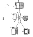
- FIG. 1 is a diagram of an image control system according to a first embodiment of the present invention.
- An image control system 1 includes an image control device 2, a printer 3, a multifunction product (MFP) 4, a facsimile machine 5, and a personal computer (PC) 6 connected to a network 10 respectively. These devices can exchange data with each other via the network 10.
- MFP multifunction product
- PC personal computer
- the image control device 2 generates, edits, and holds image data of documents and photographs.
- image data which is generated, edited, and held by the image control device 2 is to be printed out
- the image data is output from the image control device 2 to the printer 3 or the MFP 4.
- the printer 3 or the MFP 4 prints out the image data, thereby obtaining a printed image.
- Another device that is connected to the network 10 and has a print output function can print out the image data using the function.
- the image control device 2 can also print out and store image data that is generated, edited, and held, by adding a fraudulent-use preventing pattern to the image data.
- An image forming apparatus detects the fraudulent-use preventing pattern added by the image control device 2 to the image data. Then the image forming apparatus carries out a processing which is carried out when the image data is fraudulently used (hereinafter, "a fraudulent-use preventing process"), based on the fraudulent-use preventing pattern.
- the printer 3 prints out image data that is output from the image control device 2 and other devices connected to the network 10.
- the MFP 4 has a copy function, a facsimile transmission function, and an email transmission function, in addition to a print output function that is similar to that of the printer 3.
- the facsimile machine 5 exchanges facsimile data with other connected devices.
- the PC 6 edits documents and images, and transmits and receives emails.
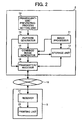
- Fig. 2 is a block diagram of the image control device and the image forming apparatus.
- the image control device 2 includes an image processor 11, a storage unit 12, a fraudulent-use-preventing-process setting unit 13, a pattern generator 14, a combined image generator 15, and a transmitter/receiver 16.
- the image processor 11 generates and edits image data.
- the image processor 11 also edits image data stored in the storage unit 12, described later, and image data obtained from other connected devices via the transmitter/receiver 16, described later.
- the storage unit 12 stores image data generated and edited by the image processor 11, and stores image data obtained from other connected devices via the transmitter/receiver 16.
- the fraudulent-use-preventing-process setting unit 13 sets a fraudulent-use preventing process for individual image data, and also sets a determination standard to determine which kind of use is a fraudulent use, to the individual image data.
- An example of the setting of a fraudulent-use preventing process is explained with reference to Figs. 3 to 8 .
- Figs. 3 and 4 are examples of a setting screen of the fraudulent-use preventing process. While a fraudulent-use preventing process can be set at an optional timing, it is assumed herein that this setting is carried out during the execution of an edit application of image data.
- a user displays a fraudulent-use-preventing-process setting screen 100 during the execution of the application.
- a pattern addition checkbox 110, a trace pattern addition checkbox 111, a print permission setting checkbox 112, a pattern selection box 113, an addition button 114, a pattern detailed setting button 115, a new pattern addition button 116, and the like are displayed on the display screen of the fraudulent-use-preventing-process setting screen 100.
- the user can set a fraudulent-use preventing process each time.
- a pattern generated by the pattern generator 14, described later can be registered based on a previous setting.
- the fraudulent-use preventing process can be set by selecting the registered pattern, thereby avoiding the work of same setting each time.
- the fraudulent-use preventing process is set by selecting a pattern.
- the pattern selection box 113 When a checkmark is placed in the pattern addition checkbox 110, the pattern selection box 113 is displayed. Pattern names of registered patterns are displayed in the pattern selection box 113. The user selects a pattern name corresponding to a fraudulent-use preventing process to be set from among the pattern names displayed in the pattern selection box 113, and depresses the addition button 114. As a result, the user can select a pattern to be added to image data being edited.
- the fraudulent-use preventing process does not need to be set to the whole image data, such as when a confidential matter is written on only the first page of plural image data.
- a part setting button 117 can be provided, and a pattern can be added to only a part of the image data.
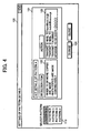
- Fig. 4 is an example of a setting of details of a pattern A selected in the pattern selection box 113.
- a pattern A detailed setting display 121 a detection item display 122 and an action display 123 are displayed.
- Detection items of the pattern A are displayed in the detection item display 122.
- a detection item is used to detect a fraudulent use of image data when a printed material added with this pattern is handled as the detection item. For example, in Fig. 4 , "When 10 or more copies are made” and “When copy is made continuously” are set as detection items of the pattern A. In other words, when 10 or more copies of the printed material added with the pattern A are made, or when the printed material is copied continuously, this is detected as a fraudulent use of the printed material.
- Actions to be taken when a detection item of the pattern A is detected are displayed in the action display 123.
- the action to be taken when a detection item is detected is a processing to be carried out when a fraudulent use of a printed material added with a pattern is detected.
- a processing to be carried out when a fraudulent use of a printed material added with a pattern is detected For example, in Fig. 4 , "Transmit email to kanri@xxx.co.jp”, “Transmit email to suzuki@xxx.co.jp”, and "Transmit facsimile message to 03-xxxx-OOOO" are set as actions to be taken when the detection items of the pattern A are detected.
- a change button 124 is depressed, thereby changing the detailed setting.
- the new pattern addition button 116 shown in Fig. 3 is depressed, thereby carrying out a desired setting and adding this setting as a new pattern.
- Figs. 5 and 6 are examples of a setting screen of a new pattern.
- a detection item selection box 131, an action selection box 132, a detailed setting box 133, and a pattern name setting box 134 are displayed in a new pattern setting display unit 130.
- Detection items 136a to 136d to be detected as a fraudulent use of data are displayed in the detection item selection box 131.
- Fig. 5 "When data is copied”, "When data is transmitted by facsimile machine”, "When data is copied by number more than assigned number”, and "When data is copied by number of times more than assigned number of times” are displayed in the detection item selection box 131. The user places a checkmark in a desired detection item checkbox, thereby selecting a detection item.
- Actions 137a to 137d to be taken when a fraudulent use of data is detected are displayed in the action selection box 132.
- “Stop print processing”, “Transmit email to designated email address”, “Transmit facsimile message to designated facsimile number”, and “Output blank paper” are displayed in the action selection box 132.
- the user places a checkmark in a desired action checkbox, thereby selecting an action to be taken when a fraudulent use of data is detected.
- Detection items and actions that are selected in the detection item selection box 131 and the action selection box 132 are displayed in the detailed setting box 133, thereby setting the details.
- An optional pattern name is input to the pattern name setting box 134, thereby setting the pattern name.
- "Pattern G" is set as a pattern name in the pattern name setting box 134.
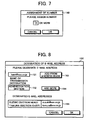
- Figs. 7 and 8 are examples of a detailed setting screen of setting items.
- a number assignment window 140 shown in Fig. 7 is activated.
- the number can be assigned to the detection item of "When data is copied by number more than assigned number”.
- 10 copies are assigned. When more than 10 copies are made, this is detected as a fraudulent use of the data.
- an email-address assignment window 150 shown in Fig. 8 is activated.
- An email-address input area 151 is displayed in the email-address assignment window 150.
- a transmission destination to which an email is to be transmitted upon detecting a fraudulent use of the data can be assigned.
- a name at the transmission destination can be input to a transmission-destination-name input area 152.
- "kanri@xxx.co.jp” is assigned as a transmission destination email address.
- "Administration Section” is input as the name of the transmission destination of the email address.
- Assignment of a transmission destination email address can be selected from an address book of email software.
- an "Add from address book” button 153 is depressed, thereby activating the address book.
- a transmission destination email address is assigned from the registered email address.
- An email can be transmitted to a plurality of transmission destinations.
- an "Add more" button 154 is depressed, thereby adding a transmission destination email address.
- Email addresses already assigned are displayed in a designated email address box 155.
- an email address suzuki@xxx.co.jp of "Suzuki section head” and an email address tamura@xxx.co.jp of "Tamura section chief” are already assigned as the transmission destinations in the designated email address box 155.
- the fraudulent-use preventing process can be also set to each time window. For example, when data is fraudulently used at night and an email is transmitted to an email address used in the company, the concerned parties cannot instantly know this fact. In this case, for example, if it is set that an email is transmitted to designated email addresses of portable telephones of the concerned parties after 6 o'clock in the afternoon, the fact of fraudulent use of the data can be promptly notified to the concerned parties, thereby increasing chances of preventing leakage of the confidential information.
- the fraudulent-use-preventing-process setting unit 13 receives the setting of the image data fraudulent-use preventing process.
- the pattern generator 14 generates a fraudulent-use preventing pattern based on the fraudulent-use preventing process set by the fraudulent-use-preventing-process setting unit 13.
- the fraudulent-use preventing pattern is a tint block that is embedded into the background of a document image to be printed.
- a fraudulent-use preventing pattern is configured by adding a tint block that appears uniformly at a print time, so that when the printed image is copied, a copy guard character string of "copy prohibited" or the like appears on the copied paper.
- Information can also be embedded into a fraudulent-use preventing pattern based on a combination of a pattern and colours. For example, to show print source information at the information leak time, date and time of the printing, a host name, a user name, and an Internet protocol (IP) address can be embedded into the fraudulent-use preventing pattern. This pattern is called a "trace pattern". Based on the output printed image, an output source can be specified, thereby analysing the state of a fraudulent use and psychologically inhibiting the user from fraudulently using the image.
- IP Internet protocol
- the image control device 2 embeds the information of the fraudulent-use preventing process set by the fraudulent-use-preventing-process setting unit 13 into the fraudulent-use preventing pattern generated by the pattern generator 14.
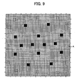
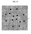
- Figs. 9 and 10 are examples of a basic pattern of the fraudulent-use preventing pattern.
- the pattern generator 14 forms a minimum basic pattern as shown in Figs. 9 and 10 based on a fraudulent-use preventing process that is set by the fraudulent-use-preventing-process setting unit 13.
- the basic pattern shown in Fig. 9 is called a "pattern A”
- the basic pattern shown in Fig. 10 is called a "pattern B”.
- a minimum square represents one pixel
- a pattern of 64x64 pixels is the basic pattern. While the layout of the dots is apparently meaningless, the layout includes a dummy pattern which prevents the fraudulent user from analysing a command embedded in the fraudulent-use preventing pattern.
- the generated basic pattern is output to the combined image generator 15 described later.
- the pattern generator 14 outputs the generated fraudulent-use preventing pattern and the information of the fraudulent-use preventing process to be carried out when the image data added with the fraudulent-use preventing pattern is used fraudulently, to the transmitter/receiver 16.
- the fraudulent-use preventing pattern and the information of the fraudulent-use preventing process that are output are transmitted to other devices connected to the network 10, and are shared by the devices that constitute the image control system 1. Each device uses these pieces of information for the setting to detect a fraudulent use of the image data.
- an operator can input the fraudulent-use preventing pattern and the information of the fraudulent-use preventing process to the devices that constitute the image control system 1 to share the information.
- the combined image generator 15 combines the basic pattern generated by the pattern generator 14 with the print image data, thereby generating a combined image.
- the image processor 11 processes or the storing unit 12 stores the print image data.
- the combined image generator 15 sequentially disposes the basic patterns generated by the pattern generator 14, in the background of the image to be printed, thereby generating a combined image.
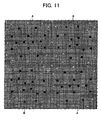
- Fig. 11 is an example of a layout of the basic patterns.
- basic patterns are embedded into the background of the print image in the layout as shown in Fig. 11 .
- A denotes the pattern A shown in Fig. 9
- B denotes the pattern B shown in Fig. 10 .
- the pattern A and the pattern B are disposed such that these patterns are not adjacent to each other.
- the transmitter/receiver 16 is connected to the network 10, and transmits the combined image generated by the combined image generator 15 to the printer 3.
- the fraudulent-use preventing pattern output from the pattern generator 14, and the fraudulent-use preventing process to be carried out when the image data added with the fraudulent-use preventing pattern is fraudulently used, are transmitted to other devices connected to the network 10.
- the image control device 2 Based on the above configuration, the image control device 2 generates, edits, and holds image data, and adds a fraudulent-use preventing pattern to the image data that is generated, edited, and held.
- the printer 3 is one example of the image forming apparatus that has a print output function.
- the printer 3 prints out image data that is output from the image control device 2.
- the printer 3 includes a receiver 21 and a printing unit 22.
- the receiver 21 receives image data of which printing is requested, from the image control device 2 or other devices connected to the network 10.
- the printing unit 22 prints out the image data received by the receiver 21.
- the document image that is printed out is added with the fraudulent-use preventing pattern. When the document image is fraudulently used, the fraudulent-use preventing process that is set by the fraudulent-use-preventing-process setting unit 13 is carried out.
- the printer 3 prints out the image data that is generated and edited by the image control device 2, thereby obtaining the printed image.
- Fig. 12 is a block diagram of the MFP 4, which is one example of the image forming apparatus that detects a fraudulent use of image data.
- the image forming apparatus can be the printer 3.
- the printer 3 does not necessary include all of the configurations described below.
- the MFP 4 includes a transmitter/receiver 300, a reader 301, a pattern detector 302, a pattern analyser 303, a fraudulent-use preventing unit 304, and a printing unit 305.
- the fraudulent-use preventing unit 304 includes an email creating unit 304a, a facsimile-message creating unit 304b, and a mask processor 304c.
- the transmitter/receiver 300 receives the fraudulent-use preventing pattern, and the fraudulent-use preventing process to be carried out when the image data added with the fraudulent-use preventing pattern is fraudulently used, from the transmitter/receiver 16 of the image control device 2.
- the transmitter/receiver 300 outputs the fraudulent-use preventing pattern and the fraudulent-use preventing process that are received, to the pattern analyser 303.
- the reader 301 reads the document image, and outputs the document image to the pattern detector 302 as image data.
- the pattern detector 302 detects whether a fraudulent-use preventing pattern is included in the image data output from the reader 301.
- the pattern detector 302 outputs the image data to the pattern analyser 303 when the image data includes the fraudulent-use preventing pattern.
- the pattern detector 302 outputs the image data to the printing unit 305 when the image data does not include the fraudulent-use preventing pattern.
- the pattern analyser 303 receives the fraudulent-use preventing pattern, and the fraudulent-use preventing process to be carried out when the image data added with the fraudulent-use preventing pattern is fraudulently used, from the transmitter/receiver 300.
- the pattern detector 302 detects the fraudulent-use preventing pattern in the image data
- the pattern analyser 303 analyses the fraudulent-use preventing process based on the detected fraudulent-use preventing pattern.
- the pattern analyser 303 outputs the information of the analysed fraudulent-use preventing process and the image data to the fraudulent-use preventing unit 304.
- the fraudulent-use preventing unit 304 executes the fraudulent-use preventing process analysed by the pattern analyser 303.
- the email creating unit 304a creates the email to be transmitted to the designated email address.
- the email creating unit 304a transmits the created email to the designated email address via the transmitter/receiver 300.
- the facsimile-message creating unit 304b When a facsimile message transmission to a designated facsimile number is assigned as a fraudulent-use preventing process, the facsimile-message creating unit 304b creates a facsimile message to be transmitted to the designated facsimile number. The facsimile-message creating unit 304b transmits the created facsimile message to the designated facsimile number via the transmitter/receiver 300.
- the mask processor 304c When a blank paper output is assigned as a fraudulent-use preventing process, the mask processor 304c carries out a mask processing to the image data to output blank paper.
- the printing unit 305 prints out image data from which a pattern is not detected by the pattern detector 302, or image data of which printing is permitted out of image data to which the fraudulent-use preventing process is carried out by the fraudulent-use preventing unit 304.
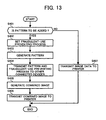
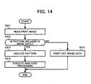
- Fig. 13 is a flowchart of a processing of the image control device adding a fraudulent-use preventing pattern to an image at the time of printing (the fraudulent-use preventing pattern can be added at an optional timing as well as at the time of printing).
- a fraudulent-use preventing pattern is simply expressed as a "pattern".
- a user decides whether a fraudulent-use preventing pattern is to be added to a document image (step S401).
- the fraudulent-use preventing pattern is to be added to a document image (step S401: Yes)
- the fraudulent-use-preventing-process setting unit 13 sets the fraudulent-use preventing process (step S402).
- the pattern generator 14 Upon receiving a selection of the fraudulent-use preventing process, the pattern generator 14 generates a fraudulent-use preventing pattern (step S403).
- the transmitter/receiver 16 transmits the fraudulent-use preventing pattern generated by the pattern generator 14 and the fraudulent-use preventing process to other connected devices (step S404).
- the combined image generator 15 combines the fraudulent-use preventing pattern with the print image, thereby generating a combined image (step S405).
- the transmitter/receiver 16 transmits the generated combined image to the printer 3 (step S406), and ends the processing shown in the flowchart.
- the transmitter/receiver 16 transmits image data to the printer 3 (step S407), and ends the processing shown in the flowchart.
- a fraudulent-use preventing process can be assigned, and a fraudulent-use preventing pattern can be added to the image data, and the result can be transmitted to the printer 3.
- the receiver 21 of the printer 3 receives the combined image and the image data that are transmitted to the printer 3 at step S406 and step S407.
- the printing unit 22 prints out the combined image and the image data, thereby obtaining a printed image.
- Fig. 14 is a flowchart of a processing carried out by the MFP at the time of copying.
- the processing carried out by the MFP 4 at the time of copying an image printed out by the printer 3 is explained next.
- the reader 301 of the MFP 4 reads a print image (step S411).
- the pattern detector 302 detects whether the image data of the read print image includes a fraudulent-use preventing pattern (step S412).
- step S412 When the image data includes a fraudulent-use preventing pattern (step S412: Yes), the pattern analyser 303 analyses the fraudulent-use preventing pattern (step S413). The fraudulent-use preventing unit 304 executes the analysed processing (step S414), and ends the processing shown in the flowchart.
- step S412 when the image data does not include a fraudulent-use preventing pattern (step S412: No), the printing unit 305 prints out the image data (step S415), and ends the processing shown in the flowchart.
- the MFP 4 can detect a fraudulent-use preventing pattern from the read image data, and execute the fraudulent-use preventing process that is analysed based on the detected fraudulent-use preventing pattern.
- the image control device 2 can optionally set a fraudulent-use preventing process.
- the fraudulent-use preventing process it is possible to assign an email transmission to a designated email address or a facsimile message transmission to a designated facsimile number.
- the concerned parties can promptly know the fact that image data is fraudulently used or is about to be fraudulently used.
- the printer 3 that prints out image data is required to have only the receiver 21 and the printing unit 22.
- the printer 3 can obtain a printed image added with a fraudulent-use preventing pattern, without using a device having a special function.
- the image control system detects a fraudulent use of an output printed image.
- an image control system according to a second embodiment limits a print out of image data, thereby preventing the image data from being fraudulently printed. For example, once generated image data cannot be printed again. Alternatively, print out of the image data is admitted to only a specified user.
- an image forming apparatus that is permitted to print out image data can be limited.
- a network configuration of the image control system according to the second embodiment is similar to that of the image control system according to the first embodiment explained with reference to Fig. 1 , and therefore, is not explained here.
- Fig. 15 is a block diagram of the image control device according to the second embodiment.
- a setting of a fraudulent-use preventing process based on a print application (a print driver) is explained.
- names of units are based on the Windows (a registered trade name) environment.
- a printing-restriction setting unit 511a is provided within a print application 511.
- the user launched the print application 511 to print a document image.
- the printing-restriction setting unit 511a sets a restriction on printing the document image.
- the restriction means that a print output of once created document image is not permitted again, or a print out of a document image is permitted to only a specific user, for example.
- the print application 511 outputs a document image to a graphics device interface (GDI) unit 512.
- the print application 511 outputs information on a restriction set by the printing-restriction setting unit 511a to a driver user interface (UI) controller 513.
- GDI graphics device interface
- UI driver user interface
- the GDI unit 512 converts the document image output by the print application 511 into graphic data.
- the GDI unit 512 also outputs the converted graphic data to a GDI interface (I/F) unit 514.
- I/F GDI interface
- the driver UI controller 513 creates a printer job language (PJL) command that expresses the restriction set by the printing-restriction setting unit 511a.
- the driver UI controller 513 also outputs the created PJL command to the GDI I/F unit 514.
- the GDI I/F unit 514 converts the graphic data output from the GDI unit 512 into intermediate data.
- the GDI I/F unit 514 receives the PJL command from the driver UI controller 513.
- the GDI I/F unit 514 outputs the converted intermediate data and the PJL command to an intermediate data processor 516.
- a pattern generator 515 generates a fraudulent-use preventing pattern. Details of the fraudulent-use preventing process pattern are similar to those according to the first embodiment, and therefore, are not explained.
- the pattern generator 515 converts the created fraudulent-use preventing pattern into intermediate data, and outputs the intermediate data to the intermediate data processor 516.
- the intermediate data processor 516 receives the intermediate data of the document image and the PJL command output from the GDI I/F unit 514, and the intermediate data of the fraudulent-use preventing pattern output from the pattern generator 515.
- the intermediate data processor 516 multiplies the intermediate data output from the GDI I/F unit 514 to integrate or print posters.
- the intermediate data processor 516 also combines the intermediate data of the document image output from the GDI I/F unit 514, and the intermediate data of the fraudulent-use preventing pattern output from the pattern generator 515.
- the intermediate data processor 516 outputs the combined intermediate data and the PJL command to a page description language (PDL) converter 517.
- PDL page description language
- the PDL converter 517 receives the intermediate data and the PJL command from the intermediate data processor 516.
- the PDL converter 517 converts the intermediate data received from the intermediate data processor 516 into a printer language as data for printing.
- the PDL converter 517 outputs the converted print data and the PJL command to a print port controller 518.
- the print port controller 518 outputs the print data and the PJL command output from the PDL converter 517 to a spooler 519.
- the spooler 519 transmits the print data and the PJL command output from the print port controller 518, to the printer 3 via the network 10.
- the print data transmitted to the printer 3 in this way is processed based on the PJL command. For example, when the number of print out is set to a constant number, a print out of the data for more than the constant number is regarded as a fraudulent printing, and the printing thereof is not carried out. When it is set that an email is to be transmitted to a designated email address when a fraudulent printing is attempted, an email is transmitted to the designated email address.
- the image control device can prevent a fraudulent use of output printed image as well as fraudulent printing of image data.
- the image control device 2 adds a fraudulent-use preventing pattern, and outputs the fraudulent-use preventing pattern to the printer 3.
- an image forming apparatus that prints out image data adds the fraudulent-use preventing pattern.
- a network configuration of the image control system is similar to that of the image control system according to the first embodiment explained with reference to Fig. 1 , and therefore, is not explained herein.
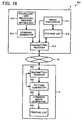
- Fig. 16 is a block diagram of the image control device and the image forming apparatus.
- the printer 3 is used as the image forming apparatus that prints out image data output from the image control device 2.
- the MFP 4 can be also used as the image forming apparatus.
- the image control device 2 includes an image processor 611, a storage unit 612, a fraudulent-use-preventing-process setting unit 613, a command generator 614, and a transmitter/receiver 615.
- the image processor 611 generates and edits image data, and also edits image data stored in the storage unit 612, described later.
- the storage unit 612 stores image data generated and edited by the image processor 611.
- the storage unit 612 also stores image data obtained from other connected devices via the transmitter/receiver 615, described later.
- the fraudulent-use-preventing-process setting unit 613 sets a processing to be carried out when individual image data are used fraudulently (hereinafter, "a fraudulent-use preventing process").
- the fraudulent-use-preventing-process setting unit 613 also sets which kind of use is a fraudulent use of the individual image data. Details of the fraudulent-use-preventing-process setting unit 613 are similar to those of the fraudulent-use-preventing-process setting unit 13 of the image control device 2 according to the first embodiment, and therefore, are not explained herein.
- the command generator 614 generates a command corresponding to the fraudulent-use preventing process set by the fraudulent-use-preventing-process setting unit 613.
- the command generated by the command generator 614 is embedded into a fraudulent-use preventing pattern generated by a pattern generator 652 of the printer 3, described later.
- the transmitter/receiver 615 is connected to the network 10, and transmits image data of which printing is requested out of the image data stored in the storage unit 612 or the image data generated and edited by the image processor 611, to the printer 3.
- the transmitter/receiver 615 transmits the command generated by the command generator 614 to the printer 3, and also exchanges data with other devices connected to the network 10.
- the printer 3 includes a transmitter/receiver 651, the pattern generator 652, a combined image generator 653, and a printing unit 654.
- the transmitter/receiver 651 is connected to the network 10, and receives the image data and the command transmitted from the image control device 2.
- the transmitter/receiver 651 outputs the received image data to the combined image generator 653, and outputs the received command to the pattern generator 652.
- the pattern generator 652 generates a fraudulent-use preventing pattern based on the command output from the transmitter/receiver 651. Details of the pattern generator 652 are similar to those of the pattern generator 14 of the image control device 2 according to the first embodiment, and therefore, are not explained herein.
- the pattern generator 652 outputs the generated fraudulent-use preventing pattern and the information of the fraudulent-use preventing process to be carried out when the image data added with the fraudulent-use preventing pattern is used fraudulently, to the transmitter/receiver 651.
- the fraudulent-use preventing pattern and the information of the fraudulent-use preventing process that are output are transmitted to other devices connected to the network 10, and are used to detect fraudulent use of image data.
- the combined image generator 653 combines the basic pattern generated by the pattern generator 652 with the print image data received by the transmitter/receiver 651, thereby generating a combined image. Details of the combined image generator 653 are similar to those of the combined image generator 15 of the image control device 2 according to the first embodiment, and therefore, are not explained herein.
- the printing unit 654 prints out the combined image generated by the combined image generator 653.
- Fig. 17 is a flowchart of a processing of the image control device transmitting print-requested image data to the printer.
- the image control device 2 determines whether a fraudulent-use preventing pattern is to be added to the image data (step S702).
- the fraudulent-use preventing pattern can be added to the image data during the editing of the image data, not only when the printing is requested.
- the fraudulent-use-preventing-process setting unit 613 sets the fraudulent-use preventing process (step S703).
- the command generator 614 generates a command corresponding to the set fraudulent-use preventing process (step S704).
- the transmitter/receiver 615 transmits the print-requested image data and the command generated at step S704 to the printer 3 (step S705), and ends the processing shown in the flowchart.
- step S705 When the fraudulent-use preventing pattern is not to be added (step S702: No), only the print-requested image data is transmitted to the printer 3 (step S706), and ends the processing shown in the flowchart.
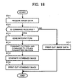
- Fig. 18 is a flowchart of the processing of the printer printing out the image data transmitted from the image control device.
- the transmitter/receiver 651 determines whether a command is also received together with the image data (step S712).
- the pattern generator 652 generates a fraudulent-use preventing pattern based on the received command (step S713).
- the pattern generator 652 transmits the generated fraudulent-use preventing pattern and the command to other devices connected to the network 10 via the transmitter/receiver 651 (step S714).
- the combined image generator 653 combines the image data with the fraudulent-use preventing pattern, thereby generating a combined image (step S715).
- the printing unit 654 prints out the combined image (step S716), and ends the processing shown in the flowchart.
- step S712 No
- the printing unit 654 prints out the image data (step S717), and ends the processing shown in the flowchart.
- the printer 3 prints out the image data transmitted from the image control device 2.
- the printer 3 can generate the fraudulent-use preventing pattern based on the fraudulent-use preventing process set by the image control device 2, add the pattern to the image data, and print out the image data added with this pattern.
- a user can set the processing to be carried out when an image is used fraudulently.
- different processes can be set depending on confidentiality of the image.
- safety of the information can be further ensured.
- the invention can be also applied to prevent information leakage due to erroneous distribution of the image data.
- a device that adds a fraudulent-use preventing pattern can be set optionally. Therefore, even when an image forming apparatus having the fraudulent-use preventing pattern adding function is not available, other devices can add the fraudulent-use preventing pattern to the document.
- the user can set a processing to be carried out when image data is used fraudulently.
- Concerned parties can promptly know the fact that image data is fraudulently used or is about to be fraudulently used.
- the image control method explained in the present application can be realized by making a computer, such as a PC or a work station, execute a program that is prepared beforehand.
- the program is stored in a computer-readable recording medium, such as a hard disk, a flexible disk, a compact disk read only memory (CD-ROM), a magneto optical disk (MO), and a digital versatile disk (DVD), and is executed by being read from the recording medium by the computer.
- the program can be a transmission medium that can be distributed via a network such as the Internet.
Landscapes
- Engineering & Computer Science (AREA)
- Multimedia (AREA)
- Signal Processing (AREA)
- Computer Security & Cryptography (AREA)
- Computer Vision & Pattern Recognition (AREA)
- Editing Of Facsimile Originals (AREA)
- Image Processing (AREA)
- Facsimile Image Signal Circuits (AREA)
- Image Analysis (AREA)
Applications Claiming Priority (1)
| Application Number | Priority Date | Filing Date | Title |
|---|---|---|---|
| JP2004272305A JP2006087034A (ja) | 2004-09-17 | 2004-09-17 | 画像制御システム、画像制御装置、画像形成装置、画像制御方法、画像制御プログラム、および記録媒体 |
Publications (2)
| Publication Number | Publication Date |
|---|---|
| EP1641238A1 EP1641238A1 (en) | 2006-03-29 |
| EP1641238B1 true EP1641238B1 (en) | 2012-06-06 |
Family
ID=35636694
Family Applications (1)
| Application Number | Title | Priority Date | Filing Date |
|---|---|---|---|
| EP05255691A Expired - Lifetime EP1641238B1 (en) | 2004-09-17 | 2005-09-14 | Method, apparatus, and computer program for preventing fraudulent use of images |
Country Status (3)
| Country | Link |
|---|---|
| US (1) | US7715056B2 (enExample) |
| EP (1) | EP1641238B1 (enExample) |
| JP (1) | JP2006087034A (enExample) |
Families Citing this family (7)
| Publication number | Priority date | Publication date | Assignee | Title |
|---|---|---|---|---|
| JP4667210B2 (ja) * | 2005-11-04 | 2011-04-06 | キヤノン株式会社 | 情報処理装置、印刷装置及びそれらの制御方法、印刷システム |
| JP4164510B2 (ja) * | 2005-12-22 | 2008-10-15 | キヤノン株式会社 | 画像処理装置、画像処理方法 |
| JP4328786B2 (ja) * | 2006-06-16 | 2009-09-09 | キヤノン株式会社 | 印刷装置及びその制御方法、プログラム、記憶媒体 |
| JP5550481B2 (ja) | 2009-08-12 | 2014-07-16 | キヤノン株式会社 | 画像形成装置、画像形成方法、及びプログラム |
| US9418292B2 (en) | 2011-10-04 | 2016-08-16 | Here Global B.V. | Methods, apparatuses, and computer program products for restricting overlay of an augmentation |
| KR101290203B1 (ko) * | 2012-05-07 | 2013-07-31 | 주식회사 파수닷컴 | 인쇄 보안 장치 및 방법 |
| JP7172667B2 (ja) | 2019-02-01 | 2022-11-16 | ブラザー工業株式会社 | サポートプログラム、情報処理装置、および印刷方法 |
Family Cites Families (18)
| Publication number | Priority date | Publication date | Assignee | Title |
|---|---|---|---|---|
| EP0597056A1 (fr) * | 1992-05-29 | 1994-05-18 | Ecole Polytechnique Federale De Lausanne | Procede de marquage de documents |
| JP3111754B2 (ja) * | 1993-07-01 | 2000-11-27 | ミノルタ株式会社 | 画像形成装置 |
| CA2129075C (en) * | 1993-10-18 | 1999-04-20 | Joseph J. Daniele | Electronic copyright royalty accounting system using glyphs |
| EP0940780B1 (en) * | 1994-01-20 | 2001-05-30 | Omron Corporation | Image processing device and method for detecting a reference pattern |
| JP3164963B2 (ja) | 1994-03-31 | 2001-05-14 | 株式会社リコー | デジタル複写機 |
| US6404926B1 (en) * | 1997-09-02 | 2002-06-11 | Sony Corporation | Apparatus and method of processing image data, transmission medium, and recording medium |
| JPH11275339A (ja) * | 1998-03-19 | 1999-10-08 | Ricoh Co Ltd | 画像形成装置 |
| JP2001184184A (ja) | 1999-12-27 | 2001-07-06 | Canon Inc | 画像処理装置、画像処理方法及び記録媒体 |
| JP2001292303A (ja) * | 2000-04-10 | 2001-10-19 | Minolta Co Ltd | 画像データ処理装置 |
| JP2001320517A (ja) | 2000-05-10 | 2001-11-16 | Fuji Xerox Co Ltd | 画像読取装置 |
| JP2003008864A (ja) | 2001-06-18 | 2003-01-10 | Ricoh Co Ltd | 画像形成装置 |
| WO2003010946A1 (en) * | 2001-07-23 | 2003-02-06 | Securelogix Corporation | Encapsulation, compression and encryption of pcm data |
| US20030164973A1 (en) * | 2002-02-19 | 2003-09-04 | Kenji Hisatomi | Printing method, broadcast data generation device, reception device and printing device |
| JP3701249B2 (ja) * | 2002-03-05 | 2005-09-28 | 京セラミタ株式会社 | 画像形成装置 |
| JP2003266863A (ja) | 2002-03-19 | 2003-09-25 | Casio Electronics Co Ltd | 印刷システム及び印刷装置 |
| US7339599B2 (en) * | 2003-01-22 | 2008-03-04 | Canon Kabushiki Kaisha | Image-processing apparatus and method, computer program, and computer-readable storage medium for discouraging illegal copying of images |
| US8332326B2 (en) * | 2003-02-01 | 2012-12-11 | Audible Magic Corporation | Method and apparatus to identify a work received by a processing system |
| JP2004237678A (ja) | 2003-02-07 | 2004-08-26 | Ricoh Co Ltd | 画像形成装置、画像形成方法、及び記憶媒体 |
-
2004
- 2004-09-17 JP JP2004272305A patent/JP2006087034A/ja active Pending
-
2005
- 2005-09-12 US US11/223,017 patent/US7715056B2/en not_active Expired - Fee Related
- 2005-09-14 EP EP05255691A patent/EP1641238B1/en not_active Expired - Lifetime
Also Published As
| Publication number | Publication date |
|---|---|
| US7715056B2 (en) | 2010-05-11 |
| EP1641238A1 (en) | 2006-03-29 |
| US20060061798A1 (en) | 2006-03-23 |
| JP2006087034A (ja) | 2006-03-30 |
Similar Documents
| Publication | Publication Date | Title |
|---|---|---|
| US20040258277A1 (en) | Information processing apparatus and computer program product | |
| JP2008268588A (ja) | 複合システム及び複合装置 | |
| EP1641238B1 (en) | Method, apparatus, and computer program for preventing fraudulent use of images | |
| KR20110027031A (ko) | 화상형성장치, 그 화상처리방법, 및 화상형성시스템 | |
| KR20110005549A (ko) | 부가정보 추가 문서를 생성하는 방법 및 이를 수행하는 화상형성장치 | |
| JP5537626B2 (ja) | 画像形成装置および画像形成システム | |
| JP4976227B2 (ja) | 画像処理装置、画像形成装置、画像処理方法及びプログラム | |
| JP2006087034A5 (enExample) | ||
| JP2006303870A (ja) | 画像形成装置及び方法 | |
| JP2019096254A (ja) | 印刷制御装置、印刷制御装置の制御方法およびプログラム | |
| JP2024032702A (ja) | 情報処理装置の制御方法 | |
| JP2008131522A (ja) | 画像処理装置、プログラムおよびコンピュータ読取可能記録媒体 | |
| JP2007201850A (ja) | 画像形成装置、画像形成方法およびプログラム | |
| JP4218714B2 (ja) | 画像処理装置、複写システム、複写方法、およびコンピュータプログラム | |
| JP2012033024A (ja) | 出力システム、作成装置、表示装置、出力方法、出力指示方法、コンピュータプログラム及び記録媒体 | |
| JP4965996B2 (ja) | 画像処理装置、画像処理方法、画像処理プログラム並びに記憶媒体 | |
| US20200145549A1 (en) | Copy method of generating generation-count information | |
| JP2010000663A (ja) | 画像形成システム | |
| JP2006001143A (ja) | 画像処理装置 | |
| JP2012190473A (ja) | 画像処理装置、画像処理システムおよび画像処理プログラム | |
| JP4321401B2 (ja) | 印刷制御装置、方法及びプログラム | |
| JP4784635B2 (ja) | 画像処理装置、画像形成装置およびプログラム | |
| JP2007034615A (ja) | 情報処理装置、印刷装置、印刷システム及びそれらの方法 | |
| JP4674539B2 (ja) | 印刷指示装置、その指示方法およびプログラム | |
| JP2008060881A (ja) | 画像送信装置、画像形成装置、プログラムおよびコンピュータ読取可能記録媒体 |
Legal Events
| Date | Code | Title | Description |
|---|---|---|---|
| PUAI | Public reference made under article 153(3) epc to a published international application that has entered the european phase |
Free format text: ORIGINAL CODE: 0009012 |
|
| 17P | Request for examination filed |
Effective date: 20050927 |
|
| AK | Designated contracting states |
Kind code of ref document: A1 Designated state(s): AT BE BG CH CY CZ DE DK EE ES FI FR GB GR HU IE IS IT LI LT LU LV MC NL PL PT RO SE SI SK TR |
|
| AX | Request for extension of the european patent |
Extension state: AL BA HR MK YU |
|
| AKX | Designation fees paid |
Designated state(s): DE ES FR GB IT NL |
|
| 17Q | First examination report despatched |
Effective date: 20101123 |
|
| RIC1 | Information provided on ipc code assigned before grant |
Ipc: H04N 1/32 20060101ALI20111026BHEP Ipc: H04N 1/00 20060101AFI20111026BHEP |
|
| GRAP | Despatch of communication of intention to grant a patent |
Free format text: ORIGINAL CODE: EPIDOSNIGR1 |
|
| GRAS | Grant fee paid |
Free format text: ORIGINAL CODE: EPIDOSNIGR3 |
|
| GRAA | (expected) grant |
Free format text: ORIGINAL CODE: 0009210 |
|
| AK | Designated contracting states |
Kind code of ref document: B1 Designated state(s): DE ES FR GB IT NL |
|
| REG | Reference to a national code |
Ref country code: GB Ref legal event code: FG4D |
|
| REG | Reference to a national code |
Ref country code: DE Ref legal event code: R096 Ref document number: 602005034514 Country of ref document: DE Effective date: 20120802 |
|
| REG | Reference to a national code |
Ref country code: NL Ref legal event code: VDEP Effective date: 20120606 |
|
| PG25 | Lapsed in a contracting state [announced via postgrant information from national office to epo] |
Ref country code: NL Free format text: LAPSE BECAUSE OF FAILURE TO SUBMIT A TRANSLATION OF THE DESCRIPTION OR TO PAY THE FEE WITHIN THE PRESCRIBED TIME-LIMIT Effective date: 20120606 |
|
| PG25 | Lapsed in a contracting state [announced via postgrant information from national office to epo] |
Ref country code: IT Free format text: LAPSE BECAUSE OF FAILURE TO SUBMIT A TRANSLATION OF THE DESCRIPTION OR TO PAY THE FEE WITHIN THE PRESCRIBED TIME-LIMIT Effective date: 20120606 |
|
| PLBE | No opposition filed within time limit |
Free format text: ORIGINAL CODE: 0009261 |
|
| STAA | Information on the status of an ep patent application or granted ep patent |
Free format text: STATUS: NO OPPOSITION FILED WITHIN TIME LIMIT |
|
| PG25 | Lapsed in a contracting state [announced via postgrant information from national office to epo] |
Ref country code: ES Free format text: LAPSE BECAUSE OF FAILURE TO SUBMIT A TRANSLATION OF THE DESCRIPTION OR TO PAY THE FEE WITHIN THE PRESCRIBED TIME-LIMIT Effective date: 20120917 |
|
| 26N | No opposition filed |
Effective date: 20130307 |
|
| REG | Reference to a national code |
Ref country code: DE Ref legal event code: R097 Ref document number: 602005034514 Country of ref document: DE Effective date: 20130307 |
|
| PGFP | Annual fee paid to national office [announced via postgrant information from national office to epo] |
Ref country code: DE Payment date: 20140922 Year of fee payment: 10 |
|
| PGFP | Annual fee paid to national office [announced via postgrant information from national office to epo] |
Ref country code: FR Payment date: 20140919 Year of fee payment: 10 Ref country code: GB Payment date: 20140919 Year of fee payment: 10 |
|
| REG | Reference to a national code |
Ref country code: DE Ref legal event code: R119 Ref document number: 602005034514 Country of ref document: DE |
|
| GBPC | Gb: european patent ceased through non-payment of renewal fee |
Effective date: 20150914 |
|
| REG | Reference to a national code |
Ref country code: FR Ref legal event code: ST Effective date: 20160531 |
|
| PG25 | Lapsed in a contracting state [announced via postgrant information from national office to epo] |
Ref country code: GB Free format text: LAPSE BECAUSE OF NON-PAYMENT OF DUE FEES Effective date: 20150914 Ref country code: DE Free format text: LAPSE BECAUSE OF NON-PAYMENT OF DUE FEES Effective date: 20160401 |
|
| PG25 | Lapsed in a contracting state [announced via postgrant information from national office to epo] |
Ref country code: FR Free format text: LAPSE BECAUSE OF NON-PAYMENT OF DUE FEES Effective date: 20150930 |