EP1617071A1 - Elektromagnetisches kraftstoffeinspritzventil - Google Patents
Elektromagnetisches kraftstoffeinspritzventil Download PDFInfo
- Publication number
- EP1617071A1 EP1617071A1 EP04722027A EP04722027A EP1617071A1 EP 1617071 A1 EP1617071 A1 EP 1617071A1 EP 04722027 A EP04722027 A EP 04722027A EP 04722027 A EP04722027 A EP 04722027A EP 1617071 A1 EP1617071 A1 EP 1617071A1
- Authority
- EP
- European Patent Office
- Prior art keywords
- valve
- movable core
- fixed core
- core
- face
- Prior art date
- Legal status (The legal status is an assumption and is not a legal conclusion. Google has not performed a legal analysis and makes no representation as to the accuracy of the status listed.)
- Granted
Links
- 239000000446 fuel Substances 0.000 title claims abstract description 66
- 238000002347 injection Methods 0.000 title claims abstract description 34
- 239000007924 injection Substances 0.000 title claims abstract description 34
- 229910000859 α-Fe Inorganic materials 0.000 claims abstract description 22
- 239000000696 magnetic material Substances 0.000 claims abstract description 17
- 230000002093 peripheral effect Effects 0.000 claims description 32
- 229910052782 aluminium Inorganic materials 0.000 claims description 26
- 229910052759 nickel Inorganic materials 0.000 claims description 26
- 229910045601 alloy Inorganic materials 0.000 claims description 24
- 239000000956 alloy Substances 0.000 claims description 24
- 239000000463 material Substances 0.000 claims description 23
- 238000004891 communication Methods 0.000 claims description 11
- 230000013011 mating Effects 0.000 claims description 11
- 229910052799 carbon Inorganic materials 0.000 claims description 8
- 229910052748 manganese Inorganic materials 0.000 claims description 8
- 229910052698 phosphorus Inorganic materials 0.000 claims description 8
- 229910052717 sulfur Inorganic materials 0.000 claims description 8
- 229910052742 iron Inorganic materials 0.000 claims description 4
- 238000005299 abrasion Methods 0.000 abstract description 32
- 230000004043 responsiveness Effects 0.000 abstract description 24
- 238000007747 plating Methods 0.000 abstract description 9
- 230000004907 flux Effects 0.000 description 27
- 238000005461 lubrication Methods 0.000 description 8
- 238000003754 machining Methods 0.000 description 8
- 230000005415 magnetization Effects 0.000 description 8
- 238000001816 cooling Methods 0.000 description 6
- 238000003466 welding Methods 0.000 description 6
- 238000002485 combustion reaction Methods 0.000 description 4
- 238000002788 crimping Methods 0.000 description 4
- 230000006872 improvement Effects 0.000 description 4
- 239000012535 impurity Substances 0.000 description 4
- 229910052720 vanadium Inorganic materials 0.000 description 4
- 230000015572 biosynthetic process Effects 0.000 description 3
- 230000003247 decreasing effect Effects 0.000 description 3
- 238000004519 manufacturing process Methods 0.000 description 3
- 230000003252 repetitive effect Effects 0.000 description 3
- 229910000831 Steel Inorganic materials 0.000 description 2
- 230000009471 action Effects 0.000 description 2
- 230000006835 compression Effects 0.000 description 2
- 238000007906 compression Methods 0.000 description 2
- 238000010276 construction Methods 0.000 description 2
- 230000003111 delayed effect Effects 0.000 description 2
- 230000000694 effects Effects 0.000 description 2
- 230000005611 electricity Effects 0.000 description 2
- 230000001747 exhibiting effect Effects 0.000 description 2
- 238000001746 injection moulding Methods 0.000 description 2
- 238000000034 method Methods 0.000 description 2
- 239000000203 mixture Substances 0.000 description 2
- 239000002244 precipitate Substances 0.000 description 2
- 230000008569 process Effects 0.000 description 2
- 239000010959 steel Substances 0.000 description 2
- 229920003002 synthetic resin Polymers 0.000 description 2
- 239000000057 synthetic resin Substances 0.000 description 2
- 229910052804 chromium Inorganic materials 0.000 description 1
- 229910052750 molybdenum Inorganic materials 0.000 description 1
- 238000005498 polishing Methods 0.000 description 1
Images


Classifications
-
- F—MECHANICAL ENGINEERING; LIGHTING; HEATING; WEAPONS; BLASTING
- F02—COMBUSTION ENGINES; HOT-GAS OR COMBUSTION-PRODUCT ENGINE PLANTS
- F02M—SUPPLYING COMBUSTION ENGINES IN GENERAL WITH COMBUSTIBLE MIXTURES OR CONSTITUENTS THEREOF
- F02M51/00—Fuel-injection apparatus characterised by being operated electrically
- F02M51/005—Arrangement of electrical wires and connections, e.g. wire harness, sockets, plugs; Arrangement of electronic control circuits in or on fuel injection apparatus
-
- F—MECHANICAL ENGINEERING; LIGHTING; HEATING; WEAPONS; BLASTING
- F02—COMBUSTION ENGINES; HOT-GAS OR COMBUSTION-PRODUCT ENGINE PLANTS
- F02M—SUPPLYING COMBUSTION ENGINES IN GENERAL WITH COMBUSTIBLE MIXTURES OR CONSTITUENTS THEREOF
- F02M51/00—Fuel-injection apparatus characterised by being operated electrically
- F02M51/06—Injectors peculiar thereto with means directly operating the valve needle
- F02M51/061—Injectors peculiar thereto with means directly operating the valve needle using electromagnetic operating means
- F02M51/0625—Injectors peculiar thereto with means directly operating the valve needle using electromagnetic operating means characterised by arrangement of mobile armatures
- F02M51/0664—Injectors peculiar thereto with means directly operating the valve needle using electromagnetic operating means characterised by arrangement of mobile armatures having a cylindrically or partly cylindrically shaped armature, e.g. entering the winding; having a plate-shaped or undulated armature entering the winding
- F02M51/0671—Injectors peculiar thereto with means directly operating the valve needle using electromagnetic operating means characterised by arrangement of mobile armatures having a cylindrically or partly cylindrically shaped armature, e.g. entering the winding; having a plate-shaped or undulated armature entering the winding the armature having an elongated valve body attached thereto
- F02M51/0675—Injectors peculiar thereto with means directly operating the valve needle using electromagnetic operating means characterised by arrangement of mobile armatures having a cylindrically or partly cylindrically shaped armature, e.g. entering the winding; having a plate-shaped or undulated armature entering the winding the armature having an elongated valve body attached thereto the valve body having cylindrical guiding or metering portions, e.g. with fuel passages
-
- F—MECHANICAL ENGINEERING; LIGHTING; HEATING; WEAPONS; BLASTING
- F02—COMBUSTION ENGINES; HOT-GAS OR COMBUSTION-PRODUCT ENGINE PLANTS
- F02M—SUPPLYING COMBUSTION ENGINES IN GENERAL WITH COMBUSTIBLE MIXTURES OR CONSTITUENTS THEREOF
- F02M61/00—Fuel-injectors not provided for in groups F02M39/00 - F02M57/00 or F02M67/00
- F02M61/16—Details not provided for in, or of interest apart from, the apparatus of groups F02M61/02 - F02M61/14
- F02M61/161—Means for adjusting injection-valve lift
-
- F—MECHANICAL ENGINEERING; LIGHTING; HEATING; WEAPONS; BLASTING
- F02—COMBUSTION ENGINES; HOT-GAS OR COMBUSTION-PRODUCT ENGINE PLANTS
- F02M—SUPPLYING COMBUSTION ENGINES IN GENERAL WITH COMBUSTIBLE MIXTURES OR CONSTITUENTS THEREOF
- F02M2200/00—Details of fuel-injection apparatus, not otherwise provided for
- F02M2200/50—Arrangements of springs for valves used in fuel injectors or fuel injection pumps
- F02M2200/505—Adjusting spring tension by sliding spring seats
-
- F—MECHANICAL ENGINEERING; LIGHTING; HEATING; WEAPONS; BLASTING
- F02—COMBUSTION ENGINES; HOT-GAS OR COMBUSTION-PRODUCT ENGINE PLANTS
- F02M—SUPPLYING COMBUSTION ENGINES IN GENERAL WITH COMBUSTIBLE MIXTURES OR CONSTITUENTS THEREOF
- F02M51/00—Fuel-injection apparatus characterised by being operated electrically
- F02M51/06—Injectors peculiar thereto with means directly operating the valve needle
- F02M51/061—Injectors peculiar thereto with means directly operating the valve needle using electromagnetic operating means
- F02M51/0614—Injectors peculiar thereto with means directly operating the valve needle using electromagnetic operating means characterised by arrangement of electromagnets or fixed armature
-
- F—MECHANICAL ENGINEERING; LIGHTING; HEATING; WEAPONS; BLASTING
- F02—COMBUSTION ENGINES; HOT-GAS OR COMBUSTION-PRODUCT ENGINE PLANTS
- F02M—SUPPLYING COMBUSTION ENGINES IN GENERAL WITH COMBUSTIBLE MIXTURES OR CONSTITUENTS THEREOF
- F02M61/00—Fuel-injectors not provided for in groups F02M39/00 - F02M57/00 or F02M67/00
- F02M61/16—Details not provided for in, or of interest apart from, the apparatus of groups F02M61/02 - F02M61/14
- F02M61/165—Filtering elements specially adapted in fuel inlets to injector
-
- F—MECHANICAL ENGINEERING; LIGHTING; HEATING; WEAPONS; BLASTING
- F02—COMBUSTION ENGINES; HOT-GAS OR COMBUSTION-PRODUCT ENGINE PLANTS
- F02M—SUPPLYING COMBUSTION ENGINES IN GENERAL WITH COMBUSTIBLE MIXTURES OR CONSTITUENTS THEREOF
- F02M61/00—Fuel-injectors not provided for in groups F02M39/00 - F02M57/00 or F02M67/00
- F02M61/16—Details not provided for in, or of interest apart from, the apparatus of groups F02M61/02 - F02M61/14
- F02M61/166—Selection of particular materials
Definitions
- the present invention relates to an electromagnetic fuel injection valve used mainly in a fuel supply system of an internal combustion engine and, in particular, to an improvement of an electromagnetic fuel injection valve that includes a valve housing having a valve seat at one end thereof, a fixed core connected to the other end of the valve housing, a valve body housed within the valve housing and carrying out opening and closing operations in cooperation with the valve seat, a movable core integrally connected to the valve body and disposed so as to oppose the fixed core, a valve spring urging the valve body in a valve-closing direction, and a coil that is disposed so as to surround the fixed core and that by energization makes the fixed core attract the movable core, thereby opening the valve body.
- Such plating layers on the movable and fixed cores as disclosed in Patent Document 1 have to be formed by a plating step, which requires a long processing time; moreover, since the thickness of the plating layers is variable, it is necessary to correct the dimensions by polishing the plating layers, the number of steps increases, and it is difficult to reduce the cost of the electromagnetic fuel injection valve. Furthermore, as disclosed in Patent Document 2, providing the stopper plate on the valve housing results in increases in the number of components and the number of assembly steps, and this is also disadvantageous in terms of reducing the cost.
- the present invention has been achieved under the above-mentioned circumstances, and it is an object of the present invention to provide an inexpensive electromagnetic fuel injection valve in which high abrasion resistance and responsiveness can be imparted to two cores without subjecting the two cores to a troublesome abrasion resistance treatment to provide a plating layer, etc., and without providing a valve body stopper plate in a valve housing.
- an electromagnetic fuel injection valve that includes a valve housing having a valve seat at one end thereof, a fixed core connected to the other end of the valve housing, a valve body that is housed within the valve housing and that carries out opening and closing operations in cooperation with the valve seat, a movable core integrally connected to the valve body and disposed so as to oppose the fixed core, a valve spring urging the valve body in a valve-closing direction, and a coil that is disposed so as to surround the fixed core and that by energization makes the fixed core attract the movable core, thereby opening the valve body, characterized in that the fixed core is made of a high hardness ferrite magnetic material, and the movable core is provided with an integrally attached stopper element that is nonmagnetic or is more weakly magnetic than the movable core, the stopper element defining a valve-opening limit for the valve body by abutting against the attracting face of
- the fixed core is made of a high hardness ferrite magnetic material, it can exhibit good magnetic properties and high abrasion resistance, the fixed core shows almost no abrasion from repetitive abutment against the stopper element, and the fuel injection characteristics can be made stable over a long period of time.
- the fixed core which is made of a high hardness ferrite magnetic material
- the number of steps can be decreased, and since the stopper element is integrally attached to the movable core, the number of components and the number of assembly steps do not increase, thereby reducing the cost.
- an electromagnetic fuel injection valve wherein the fixed core is made of an alloy containing 10 to 20 % by weight of Cr, 0.1 % by weight of Si, 1 % by weight or more of at least one of Al and Ni, and ferrite Fe, Mn, C, P, and S as the remainder, the total of Al and Ni being 1.15 to 6 % by weight.
- an electromagnetic fuel injection valve wherein the stopper element is press-fitted in a mating recess formed on the attracting face of the movable core so that a portion of the stopper element projects from the attracting face, and a tapered face or arc-shaped face is formed on the outer periphery of the extremity of the stopper element on the press-fitting side.
- the material of the stopper element can be freely selected from nonmagnetic materials irrespective of the material of the movable core and the valve body. Furthermore, the stopper element can be fixed to the movable core simply by press-fitting and, moreover, since the tapered face or arc-shaped face of the outer periphery of the extremity of the stopper element can be smoothly guided along the inner peripheral face of the mating recess when press-fitting, the formation of swarf can be prevented. Furthermore, by dimensional management of the amount of protrusion of the stopper element, the air gap can be obtained precisely and easily.
- an electromagnetic fuel injection valve wherein the stopper element is formed integrally with the valve body so that the element is disposed so as to run through the movable core.
- valve body and the stopper element can be made of a nonmagnetic or weakly magnetic material irrespective of the material of the movable core, and the durability of the valve body and the stopper element can be improved while at the same time enabling residual magnetization to be quickly lost when the coil is de-energized.
- an electromagnetic fuel injection valve that includes a valve housing having a valve seat at one end thereof, a fixed core connected to the other end of the valve housing, a valve body housed within the valve housing and having a valve portion that works in cooperation with the valve seat and a valve stem portion connected to the valve portion, a movable core connected to the valve stem portion and disposed so as to oppose the fixed core, a valve spring urging the valve body in a valve-closing direction, and a coil that is disposed so as to surround the fixed core and that by energization makes the fixed core attract the movable core, thereby opening the valve body, the valve body and the movable core being formed integrally from the same material so as to form a valve assembly, characterized in that the valve assembly is made of a high hardness ferrite magnetic material, and the valve assembly has a lengthwise hole and a lateral hole formed as fuel passages, the lengthwise hole starting from an end face of the valve housing
- the valve assembly which is made of the high hardness ferrite magnetic material, can exhibit good magnetic properties and high abrasion resistance, and the fuel injection characteristics can be stabilized over a long period of time. Furthermore, since the valve assembly does not require any special abrasion resistance treatment, the number of production steps can be reduced, and as well as there being a small number of components, the cost can be reduced.
- valve assembly has the lengthwise hole, which starts from the end face of the movable core and is blocked by the valve portion, and the lateral hole, which provides communication between the lengthwise hole and the interior of the valve housing, the holes being formed as fuel passages, a substantial amount of surplus material can be eliminated from the valve assembly, the weight thereof can therefore be greatly reduced, and the responsiveness to magnetic force can be improved.
- an electromagnetic fuel injection valve wherein the valve assembly is made of an alloy containing 10 to 20 % by weight of Cr, 0.1 % by weight of Si, 1 % by weight or more of at least one of Al and Ni, and ferrite Fe, Mn, C, P, and S as the remainder, the total of Al and Ni being 1.15 to 6 % by weight.
- an electromagnetic fuel injection valve wherein the lateral hole is made to open on the outer peripheral face of the movable core.
- fuel is guided to the periphery of the movable core from the lengthwise hole via the lateral hole, thus achieving lubrication and cooling of the movable core, and also enabling air bubbles generated around the movable core to be diverted to the lengthwise hole side via the lateral hole, thereby preventing the air bubbles from moving toward the valve seat.
- an electromagnetic fuel injection valve wherein the valve seat is formed in a conical shape, the valve portion, which is seated on the valve seat, is formed in a hemispherical shape, the lengthwise hole is formed so as to pass through the center of the sphere of the valve portion and be blocked, a journal portion is formed integrally with the valve stem portion, the journal portion being supported slidably on an inner peripheral face of the valve housing, and the lateral hole is made to open on an outer peripheral face of the valve stem portion in the vicinity of the journal portion.
- the opening and closing attitude of the valve assembly can be stabilized by the journal portion sliding on the inner peripheral face of the valve housing; moreover, fuel is guided to the journal portion from the lengthwise hole via the lateral hole, thus achieving lubrication and cooling of the journal portion, and also enabling air bubbles generated around the journal portion to be diverted to the lengthwise hole side via the lateral hole, thereby preventing the air bubbles from moving toward the valve seat.
- valve seat is formed in the conical shape and the valve body is formed in the hemispherical shape, centering of the valve body is excellent, and the valve can be reliably closed at all times.
- the lengthwise hole which starts from the movable core, extends toward the vicinity of the surface of the extremity of the hemispherical valve portion, the lengthwise hole together with the lateral hole enable a substantial amount of surplus material to be eliminated from the valve assembly, thereby giving a lightweight valve assembly and, as a result, improving the responsiveness.
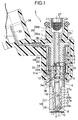
- FIG. 1 to FIG. 3 A first embodiment of the present invention shown in FIG. 1 to FIG. 3 is now explained.
- a valve housing 2 of an electromagnetic fuel injection valve I for an internal combustion engine is formed from a cylindrical valve seat member 3 having a valve seat 8 at its front end, a magnetic cylinder 4 coaxially joined to a rear end section of the valve seat member 3, and a nonmagnetic cylinder 6 coaxially joined to the rear end of the magnetic cylinder 4.
- the valve seat member 3 has on its rear end section a linking tubular portion 3a that projects, with an annular shoulder portion 3b, toward the magnetic cylinder 4 from an outer peripheral face of the valve seat member 3.
- this linking tubular portion 3a in the inner peripheral face of the front end portion of the magnetic cylinder 4 so as to make the front end face of the magnetic cylinder 4 abut against the annular shoulder portion 3b, the valve seat member 3 and the magnetic cylinder 4 are joined to each other coaxially with a liquid-tight joint.
- the magnetic cylinder 4 and the nonmagnetic cylinder 6 are joined to each other coaxially with a liquid-tight joint by abutting opposing end faces against each other and laser beam welding all the way around.
- the valve seat member 3 includes a valve opening 7 opening on its front end face, a conical valve seat 8 extending from the inner end of the valve opening 7, and a cylindrical guide hole 9 extending from a large diameter portion of the valve seat 8.
- Welded to the front end face of the valve seat member 3 with a liquid-tight weld is the entire periphery of a steel injector plate 10 having a plurality of fuel injection holes 11 communicating with the valve opening 7.
- a hollow cylindrical fixed core 5 is fixed in a liquid-tight manner by press-fitting into the inner peripheral face of the nonmagnetic cylinder 6 from the rear end side thereof.
- a part of the front end portion of the nonmagnetic cylinder 6 does not have the fixed core 5 fitted thereinto, and a valve assembly V is housed within the valve housing 2 extending from that part to the valve seat member 3.
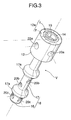
- the valve assembly V is formed from a valve body 18 and a movable core 12.
- the valve body 18 includes a hemispherical valve portion 16 for opening and closing the valve opening 7 in corporation with the valve seat 8, and a valve stem portion 17 supporting the valve portion 16.
- the movable core 12 is connected to the valve stem portion 17, extends from the magnetic cylinder 4 into the nonmagnetic cylinder 6, and is inserted into these cylinders so as to coaxially oppose the fixed core 5.
- the valve stem portion 17 is formed so as to have a smaller diameter than that of the guide hole 9, and a pair of front and rear journal portions 17a are integrally formed on the outer periphery of the valve stem portion 17 so that the journal portions 17a project radially outward and are supported slidably on the inner peripheral face of the guide hole 9.
- the journal portions 17a are disposed so as to form as large a gap as possible in the axial direction.
- the valve assembly V is provided with a lengthwise hole 19, a plurality of first lateral holes 20a, a plurality of second lateral holes 20b, and a plurality of third lateral holes 20c.
- the lengthwise hole 19 extends from the rear end face of the movable core 12 to beyond the center O of the sphere of the hemispherical valve portion 16 and is blocked; the plurality of first lateral holes 20a provide communication between the lengthwise hole 19 and the outer periphery of the movable core 12, the plurality of second lateral holes 20b provide communication between the lengthwise hole 19 and the outer peripheral face of the valve stem portion 17 between the journal portions 17a, and the plurality of third lateral holes 20c provide communication between the lengthwise hole 19 and the outer periphery of the valve stem portion 17 that is toward the valve portion 16 relative to the front-side journal portion 17a.
- the third lateral holes 20c are desirably disposed forward of the center O of the sphere of the valve portion 16, and the front-side journal portion 17a is desirably disposed as close as possible to the center O of sphere of the valve portion 16.
- An annular spring seat 24 facing the fixed core 5 side is formed partway along the lengthwise hole 19.
- the fixed core 5 has a lengthwise hole 21 communicating with the lengthwise hole 19 of the movable core 12, and has a fuel inlet tube 26 integrally connected to the rear end of the fixed core 5, the lengthwise hole 21 communicating with the interior of the fuel inlet tube 26.
- the fuel inlet tube 26 is formed from a reduced-diameter portion 26a extending from the rear end of the fixed core 5, and an enlarged-diameter portion 26b extending from the reduced-diameter portion 26a.
- a valve spring 22 is provided in compression between the spring seat 24 and a pipe-shaped retainer 23 inserted or lightly press-fitted into the lengthwise hole 21 from the reduced-diameter portion 26a, the valve spring 22 urging the movable core 12 in a direction to close the valve body 18.
- the set load of the valve spring 22 is adjusted by the depth to which the retainer 23 is fitted into the lengthwise hole 21, and after adjustment the outer peripheral wall of the reduced-diameter portion 26a is partially crimped inward so as to fix the retainer 23 to the reduced-diameter portion 26a.
- a fuel filter 27 is mounted in the enlarged-diameter portion 26b.
- the fixed core 5 is made of a high hardness ferrite magnetic material and, specifically, is formed by machining an alloy having the following composition. Cr ... 10 to 20 % by weight Si ⁇ 0.1 % by weight Al and Ni ⁇ both included, at least one thereof being 1 % by weight or more, and the total thereof being 1.15 to 6 % by weight Remainder ⁇ ferrite Fe and, as impurities, Mn, C, P, and S
- the total of Al and Ni being 1.15 to 6 % by weight contributes in particular to improvements in the abrasion resistance, the magnetic force, and the responsiveness of the fixed core 5 and the valve assembly V. That is, about 95% of the total content of Al and Ni is a precipitate, and this greatly influences the hardness, the magnetic flux density, and the volume resistivity of the fixed core 5 and the valve assembly V. It is desirable for the hardness to be high in order to obtain the abrasion resistance, for the magnetic flux density to be large in order to increase the magnetic force, and for the volume resistivity to be small in order to improve the responsiveness.
- the hardness of the alloy is 200 to 400 Hmv. This range of hardness is sufficient to impart adequate abrasion resistance to the fixed core 5 and the valve assembly V without subjecting them to any special abrasion resistance treatment such as plating after machining of the alloy. Since no special abrasion resistance treatment is required, the number of steps is decreased, and the cost of the fixed core 5 and the valve assembly V can be reduced.
- the Cr (10 to 20 % by weight), Si (0.1 % by weight), ferrite Fe and impurities Mn, C, P, and S as the remainder of the above alloy are those generally contained in a conventional core.
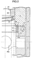
- a mating recess 13 is formed on the attracting face 12a of the movable core 12 facing the attracting face 5a of the fixed core 5, and a collar-shaped stopper element 14 surrounding the valve spring 22 is press-fitted into the mating recess 13, or is fitted and then fixed into the mating recess 13 by welding or crimping.
- a tapered face 14a or an arc-shaped face is formed on the outer periphery of the extremity of the stopper element 14 on the press-fitting side.
- the stopper element 14 is made of a nonmagnetic material such as, for example, JIS SUS304.
- the stopper element 14 projects from the attracting face 12a of the movable core 12, and is normally disposed so as to oppose the attracting face 5a of the fixed core 5 across a gap s corresponding to a valve-opening stroke of the valve body 18.
- the attracting face 12a of the movable core 12 is formed from a reference attracting face F and a protruding attracting face f, the reference attracting face F facing the attracting face 5a across a predetermined air gap g when the stopper element 14 abuts against the fixed core 5, and the protruding attracting face f protruding from the reference attracting face F toward the fixed core 5.
- the predetermined air gap g is set so that, when the coil 30 is de-energized from an energized state, the residual magnetic flux between the two cores 5 and 12 is quickly lost.
- the amount of protrusion of the protruding attracting face f relative to the reference attracting face F is set in a range such that, even when the stopper element 14 abuts against the fixed core 5, the protruding attracting face f does not make contact with the attracting face of the fixed core 5, and in this arrangement the area of the protruding attracting face f is set to be narrower than that of the reference attracting face F so that loss of residual magnetization is not hindered by the protruding attracting face f .
- the protruding attracting face f is formed in an annular shape so as to surround the stopper element 14, and the reference attracting face F is formed on the outer periphery of the protruding attracting face f.
- the end face of the stopper element 14 and the reference and protruding attracting faces F and f are simultaneously finished by grinding after the stopper element 14 is mounted in the movable core 12.
- a coil assembly 28 is fitted onto the outer periphery of the valve housing 2 so as to correspond to the fixed core 5 and the movable core 12.
- This coil assembly 28 is formed from a bobbin 29 and a coil 30, the bobbin 29 being fitted onto the outer peripheral faces of the rear end section of the magnetic cylinder 4 and the whole of the nonmagnetic cylinder 6, and the coil 30 being wound around the bobbin 29.
- the front end of a coil housing 31 surrounding the coil assembly 28 is welded to the outer peripheral face of the magnetic cylinder 4, and the rear end thereof is welded to the outer peripheral face of a yoke 5b that projects in a flange shape from the outer periphery of a rear end section of the fixed core 5.
- the coil housing 31 is cylindrical and has an axially extending slit 31 a formed on one side thereof.
- the coil housing 31, the coil assembly 28, the fixed core 5, and the front half of the fuel inlet tube 26 are sealed in by a synthetic resin cover 32 by injection molding.
- the coil housing 31 is filled with the cover 32 through the slit 31 a.
- a coupler 34 housing a connection terminal 33 connected to the coil 30 is integrally joined to a middle section of the cover 32.
- valve assembly V When the coil 30 is in a de-energized state, the valve assembly V is pressed forward by the urging of the valve spring 22, the hemispherical valve portion 16 of the valve body 18 is seated on the conical valve seat 8, and a good valve-closed state can be always obtained by virtue of the centering action of the valve portion 16.
- Fuel pumped from a fuel pump (not illustrated) to the fuel inlet tube 26 passes through the interior of the pipe-shape retainer 23, the lengthwise hole 19, and the first to third lateral holes 20a to 20c of the valve assembly V, is held in readiness within the interior of the valve seat member 3, and is supplied for lubrication around the journal portions 17a of the valve body 18.
- the stopper element 14 fixedly fitted into the movable core 12 of the valve assembly V abuts against the attracting face 5a of the fixed core 5, thus defining the valve-opening limit for the valve body 18, and the attracting face 12a of the movable core 12 faces the attracting face 5a of the fixed core 5 across the air gap g , thereby avoiding direct contact with the fixed core 5.
- the air gap g can be obtained precisely and easily; this, together with the effect of the stopper element 14 being nonmagnetic, enables residual magnetization between the two cores 5 and 12 to be quickly lost when the coil 30 is de-energized, thereby improving the valve-closing responsiveness of the valve body 18.
- the stopper element 14 is formed from a member separate from the movable core 12, a nonmagnetic material can be selected freely, irrespective of the material of the movable core 12 and the valve body 18.
- the stopper element 14 can be fixed to the movable core 12 simply by press-fitting and, moreover, since the tapered face 14a or arc-shaped face of the outer periphery of the extremity of the stopper element 14 can be guided smoothly along the inner peripheral face of the mating recess 13 during press-fitting, formation of swarf can be prevented.
- the fixed core 5 and the valve assembly V are made of a high hardness ferrite magnetic material as described above, the fixed core 5 and the movable core 12 of the valve assembly V cooperate so as to exhibit good magnetic properties, thereby improving the valve-opening responsiveness of the valve body 18.
- the fixed core 5 exhibits excellent abrasion resistance toward repetitive impact received from the stopper element 14, thus contributing to the valve-opening stroke of the valve body 18 being maintained appropriately over a long period of time.
- the valve portion 16 and the journal portions 17a of the valve body 18 of the valve assembly V exhibit excellent abrasion resistance toward abutment against the valve seat 8 and sliding in the guide hole 9, thereby making the operation of the valve body 18 stable over a long period of time.
- the fixed core 5 and the valve assembly V which are made of a high hardness ferrite magnetic material, do not require any special abrasion resistance treatment, the number of production steps is reduced. Furthermore, since the stopper element 14 is attached integrally to the movable core 12, the number of components and the number of assembly steps are not increased, and the cost is thus reduced.
- valve assembly V is provided, as fuel passages, with the lengthwise hole 19 that starts from the end face of the movable core 12 and is blocked by the valve portion 16, and the first to third lateral holes 20a to 20c that provide communication between the lengthwise hole 19 and the interior of the valve housing 2.
- the lengthwise hole 19 extends beyond the center O of the sphere of the hemispherical valve portion 16 toward the vicinity of the surface of the extremity thereof, the fuel passages eliminate a substantial amount of surplus material of the valve assembly V, and as a result the weight of the valve assembly V is greatly reduced and the responsiveness to magnetic force can be improved.
- the first lateral holes 20a not only contribute to lubrication and cooling of the movable core 12 by guiding fuel to the periphery of the movable core 12 from the lengthwise hole 19, but also guide and divert air bubbles generated therein toward the lengthwise hole 19, thereby preventing effectively the air bubbles from moving toward the valve seat 8.
- the second and third lateral holes 20b and 20c not only contribute to lubrication and cooling of the valve body 18 and, in particular, the journal portions 17a by guiding fuel from the lengthwise hole 19 to the peripheries thereof, but also guide and divert air bubbles generated therein toward the lengthwise hole 19, thereby preventing effectively the air bubbles from moving toward the valve seat 8.
- the attracting face 12a of the movable core 12 is formed from the protruding attracting face f , which has a small area, and the reference attracting face F, which has a large area, during the initial stages of energization of the coil 30, even when there is little magnetic flux generated, the magnetic flux is concentrated through the relatively small area of the protruding attracting face f , the magnetic flux density of the protruding attracting face f is increased, and the magnetic responsiveness of the movable core 12 is improved. Moreover, since the protruding attracting face f is in the central part of the movable core 12, the attractive force due to the magnetic force acts on the central part of the movable core 12, and its attitude when it starts to move can be stabilized.
- valve-opening responsiveness of the valve body 18 can thus be improved.
- a valve body 18 and a movable core 12 of a valve assembly V are formed from separate members, and a cylindrical stopper element 14 and a flange 35 are integrally formed on a valve stem portion 17 of the valve body 18, the cylindrical stopper element 14 running through a linking hole 36 of the movable core 12 and being fixed to the movable core 12, and the flange 35 abutting against the front end face of the movable core 12 so as to restrict the depth to which the stopper element 14 is fitted into the movable core 12.
- Fixing of the stopper element 14 to the movable core 12 is carried out by press-fitting, crimping, or welding.
- the valve body 18 and the stopper element 14 are formed by machining a nonmagnetic material or a material that is more weakly magnetic than the movable core 12, such as a JIS SUS440C alloy.
- valve body 18 and the stopper element 14 from a high hardness nonmagnetic or weakly magnetic material irrespective of the material of the movable core 12, and the durability of the valve body 18 and the stopper element 14 can be improved while at the same time enabling residual magnetization between the two cores to be quickly lost when the coil is de-energized.
- the present invention is not limited to the above-mentioned embodiments, and can be modified in a variety of ways without departing from the spirit and scope of the present invention.
- a journal portion slidably supported by the inner peripheral face of the magnetic cylinder 4 can be formed on the outer peripheral face of the movable core 12.
- FIG. 1 to FIG. 3 A first embodiment of the present invention shown in FIG. 1 to FIG. 3 is now explained.
- a valve housing 2 of an electromagnetic fuel injection valve I for an internal combustion engine is formed from a cylindrical valve seat member 3 having a valve seat 8 at its front end, a magnetic cylinder 4 coaxially joined to a rear end section of the valve seat member 3, and a nonmagnetic cylinder 6 coaxially joined to the rear end of the magnetic cylinder 4.
- the valve seat member 3 has on its rear end section a linking tubular portion 3a that projects, with an annular shoulder portion 3b, toward the magnetic cylinder 4 from an outer peripheral face of the valve seat member 3.
- this linking tubular portion 3a in the inner peripheral face of the front end portion of the magnetic cylinder 4 so as to make the front end face of the magnetic cylinder 4 abut against the annular shoulder portion 3b, the valve seat member 3 and the magnetic cylinder 4 are joined to each other coaxially with a liquid-tight joint.
- the magnetic cylinder 4 and the nonmagnetic cylinder 6 are joined to each other coaxially with a liquid-tight joint by abutting opposing end faces against each other and laser beam welding all the way around.
- the valve seat member 3 includes a valve opening 7 opening on its front end face, a conical valve seat 8 extending from the inner end of the valve opening 7, and a cylindrical guide hole 9 extending from a large diameter portion of the valve seat 8.
- Welded to the front end face of the valve seat member 3 with a liquid-tight weld is the entire periphery of a steel injector plate 10 having a plurality of fuel injection holes 11 communicating with the valve opening 7.
- a hollow cylindrical fixed core 5 is fixed in a liquid-tight manner by press-fitting into the inner peripheral face of the nonmagnetic cylinder 6 from the rear end side thereof.
- a part of the front end portion of the nonmagnetic cylinder 6 does not have the fixed core 5 fitted thereinto, and a valve assembly V is housed within the valve housing 2 extending from that part to the valve seat member 3.
- the valve assembly V is formed from a valve body 18 and a movable core 12.
- the valve body 18 includes a hemispherical valve portion 16 for opening and closing the valve opening 7 in corporation with the valve seat 8, and a valve stem portion 17 supporting the valve portion 16.
- the movable core 12 is connected to the valve stem portion 17, extends from the magnetic cylinder 4 into the nonmagnetic cylinder 6, and is inserted into these cylinders so as to coaxially oppose the fixed core 5.
- the valve stem portion 17 is formed so as to have a smaller diameter than that of the guide hole 9, and a pair of front and rear journal portions 17a are integrally formed on the outer periphery of the valve stem portion 17 so that the journal portions 17a project radially outward and are supported slidably on the inner peripheral face of the guide hole 9.
- the journal portions 17a are disposed so as to form as large a gap as possible in the axial direction.
- the valve assembly V is provided with a lengthwise hole 19, a plurality of first lateral holes 20a, a plurality of second lateral holes 20b, and a plurality of third lateral holes 20c.
- the lengthwise hole 19 extends from the rear end face of the movable core 12 to beyond the center O of the sphere of the hemispherical valve portion 16 and is blocked; the plurality of first lateral holes 20a provide communication between the lengthwise hole 19 and the outer periphery of the movable core 12, the plurality of second lateral holes 20b provide communication between the lengthwise hole 19 and the outer peripheral face of the valve stem portion 17 between the journal portions 17a, and the plurality of third lateral holes 20c provide communication between the lengthwise hole 19 and the outer periphery of the valve stem portion 17 that is toward the valve portion 16 relative to the front-side journal portion 17a.
- the third lateral holes 20c are desirably disposed forward of the center O of the sphere of the valve portion 16, and the front-side journal portion 17a is desirably disposed as close as possible to the center O of sphere of the valve portion 16.
- An annular spring seat 24 facing the fixed core 5 side is formed partway along the lengthwise hole 19.
- the fixed core 5 has a lengthwise hole 21 communicating with the lengthwise hole 19 of the movable core 12, and has a fuel inlet tube 26 integrally connected to the rear end of the fixed core 5, the lengthwise hole 21 communicating with the interior of the fuel inlet tube 26.
- the fuel inlet tube 26 is formed from a reduced-diameter portion 26a extending from the rear end of the fixed core 5, and an enlarged-diameter portion 26b extending from the reduced-diameter portion 26a.
- a valve spring 22 is provided in compression between the spring seat 24 and a pipe-shaped retainer 23 inserted or lightly press-fitted into the lengthwise hole 21 from the reduced-diameter portion 26a, the valve spring 22 urging the movable core 12 in a direction to close the valve body 18.
- the set load of the valve spring 22 is adjusted by the depth to which the retainer 23 is fitted into the lengthwise hole 21, and after adjustment the outer peripheral wall of the reduced-diameter portion 26a is partially crimped inward so as to fix the retainer 23 to the reduced-diameter portion 26a.
- a fuel filter 27 is mounted in the enlarged-diameter portion 26b.
- the fixed core 5 is made of a high hardness ferrite magnetic material and, specifically, is formed by machining an alloy having the following composition. Cr ⁇ 10 to 20 % by weight Si ... 0.1 % by weight Al and Ni ... both included, at least one thereof being 1 % by weight or more, and the total thereof being 1.15 to 6 % by weight Remainder ... ferrite Fe and, as impurities, Mn, C, P, and S
- the total of Al and Ni being 1.15 to 6 % by weight contributes in particular to improvements in the abrasion resistance, the magnetic force, and the responsiveness of the fixed core 5 and the valve assembly V. That is, about 95% of the total content of Al and Ni is a precipitate, and this greatly influences the hardness, the magnetic flux density, and the volume resistivity of the fixed core 5 and the valve assembly V. It is desirable for the hardness to be high in order to obtain the abrasion resistance, for the magnetic flux density to be large in order to increase the magnetic force, and for the volume resistivity to be small in order to improve the responsiveness.
- the hardness of the alloy is 200 to 400 Hmv. This range of hardness is sufficient to impart adequate abrasion resistance to the fixed core 5 and the valve assembly V without subjecting them to any special abrasion resistance treatment such as plating after machining of the alloy. Since no special abrasion resistance treatment is required, the number of steps is decreased, and the cost of the fixed core 5 and the valve assembly V can be reduced.
- the Cr (10 to 20 % by weight), Si (0.1 % by weight), ferrite Fe and impurities Mn, C, P, and S as the remainder of the above alloy are those generally contained in a conventional core.
- a mating recess 13 is formed on the attracting face 12a of the movable core 12 facing the attracting face 5a of the fixed core 5, and a collar-shaped stopper element 14 surrounding the valve spring 22 is press-fitted into the mating recess 13, or is fitted and then fixed into the mating recess 13 by welding or crimping.
- a tapered face 14a or an arc-shaped face is formed on the outer periphery of the extremity of the stopper element 14 on the press-fitting side.
- the stopper element 14 is made of a nonmagnetic material such as, for example, JIS SUS304.
- the stopper element 14 projects from the attracting face 12a of the movable core 12, and is normally disposed so as to oppose the attracting face 5a of the fixed core 5 across a gap s corresponding to a valve-opening stroke of the valve body 18.
- the attracting face 12a of the movable core 12 is formed from a reference attracting face F and a protruding attracting face f, the reference attracting face F facing the attracting face 5a across a predetermined air gap g when the stopper element 14 abuts against the fixed core 5, and the protruding attracting face f protruding from the reference attracting face F toward the fixed core 5.
- the predetermined air gap g is set so that, when the coil 30 is de-energized from an energized state, the residual magnetic flux between the two cores 5 and 12 is quickly lost.
- the amount of protrusion of the protruding attracting face f relative to the reference attracting face F is set in a range such that, even when the stopper element 14 abuts against the fixed core 5, the protruding attracting face f does not make contact with the attracting face of the fixed core 5, and in this arrangement the area of the protruding attracting face f is set to be narrower than that of the reference attracting face F so that loss of residual magnetization is not hindered by the protruding attracting face f .
- the protruding attracting face f is formed in an annular shape so as to surround the stopper element 14, and the reference attracting face F is formed on the outer periphery of the protruding attracting face f.
- the end face of the stopper element 14 and the reference and protruding attracting faces F and f are simultaneously finished by grinding after the stopper element 14 is mounted in the movable core 12.
- a coil assembly 28 is fitted onto the outer periphery of the valve housing 2 so as to correspond to the fixed core 5 and the movable core 12.
- This coil assembly 28 is formed from a bobbin 29 and a coil 30, the bobbin 29 being fitted onto the outer peripheral faces of the rear end section of the magnetic cylinder 4 and the whole of the nonmagnetic cylinder 6, and the coil 30 being wound around the bobbin 29.
- the front end of a coil housing 31 surrounding the coil assembly 28 is welded to the outer peripheral face of the magnetic cylinder 4, and the rear end thereof is welded to the outer peripheral face of a yoke 5b that projects in a flange shape from the outer periphery of a rear end section of the fixed core 5.
- the coil housing 31 is cylindrical and has an axially extending slit 31 a formed on one side thereof.
- the coil housing 31, the coil assembly 28, the fixed core 5, and the front half of the fuel inlet tube 26 are sealed in by a synthetic resin cover 32 by injection molding.
- the coil housing 31 is filled with the cover 32 through the slit 31 a.
- a coupler 34 housing a connection terminal 33 connected to the coil 30 is integrally joined to a middle section of the cover 32.
- valve assembly V When the coil 30 is in a de-energized state, the valve assembly V is pressed forward by the urging of the valve spring 22, the hemispherical valve portion 16 of the valve body 18 is seated on the conical valve seat 8, and a good valve-closed state can be always obtained by virtue of the centering action of the valve portion 16.
- Fuel pumped from a fuel pump (not illustrated) to the fuel inlet tube 26 passes through the interior of the pipe-shape retainer 23, the lengthwise hole 19, and the first to third lateral holes 20a to 20c of the valve assembly V, is held in readiness within the interior of the valve seat member 3, and is supplied for lubrication around the journal portions 17a of the valve body 18.
- the stopper element 14 fixedly fitted into the movable core 12 of the valve assembly V abuts against the attracting face 5a of the fixed core 5, thus defining the valve-opening limit for the valve body 18, and the attracting face 12a of the movable core 12 faces the attracting face 5a of the fixed core 5 across the air gap g , thereby avoiding direct contact with the fixed core 5.
- the air gap q can be obtained precisely and easily; this, together with the effect of the stopper element 14 being nonmagnetic, enables residual magnetization between the two cores 5 and 12 to be quickly lost when the coil 30 is de-energized, thereby improving the valve-closing responsiveness of the valve body 18.
- the stopper element 14 is formed from a member separate from the movable core 12, a nonmagnetic material can be selected freely, irrespective of the material of the movable core 12 and the valve body 18.
- the stopper element 14 can be fixed to the movable core 12 simply by press-fitting and, moreover, since the tapered face 14a or arc-shaped face of the outer periphery of the extremity of the stopper element 14 can be guided smoothly along the inner peripheral face of the mating recess 13 during press-fitting, formation of swarf can be prevented.
- the fixed core 5 and the valve assembly V are made of a high hardness ferrite magnetic material as described above, the fixed core 5 and the movable core 12 of the valve assembly V cooperate so as to exhibit good magnetic properties, thereby improving the valve-opening responsiveness of the valve body 18.
- the fixed core 5 exhibits excellent abrasion resistance toward repetitive impact received from the stopper element 14, thus contributing to the valve-opening stroke of the valve body 18 being maintained appropriately over a long period of time.
- the valve portion 16 and the journal portions 17a of the valve body 18 of the valve assembly V exhibit excellent abrasion resistance toward abutment against the valve seat 8 and sliding in the guide hole 9, thereby making the operation of the valve body 18 stable over a long period of time.
- the fixed core 5 and the valve assembly V which are made of a high hardness ferrite magnetic material, do not require any special abrasion resistance treatment, the number of production steps is reduced. Furthermore, since the stopper element 14 is attached integrally to the movable core 12, the number of components and the number of assembly steps are not increased, and the cost is thus reduced.
- valve assembly V is provided, as fuel passages, with the lengthwise hole 19 that starts from the end face of the movable core 12 and is blocked by the valve portion 16, and the first to third lateral holes 20a to 20c that provide communication between the lengthwise hole 19 and the interior of the valve housing 2.
- the lengthwise hole 19 extends beyond the center O of the sphere of the hemispherical valve portion 16 toward the vicinity of the surface of the extremity thereof, the fuel passages eliminate a substantial amount of surplus material of the valve assembly V, and as a result the weight of the valve assembly V is greatly reduced and the responsiveness to magnetic force can be improved.
- the first lateral holes 20a not only contribute to lubrication and cooling of the movable core 12 by guiding fuel to the periphery of the movable core 12 from the lengthwise hole 19, but also guide and divert air bubbles generated therein toward the lengthwise hole 19, thereby preventing effectively the air bubbles from moving toward the valve seat 8.
- the second and third lateral holes 20b and 20c not only contribute to lubrication and cooling of the valve body 18 and, in particular, the journal portions 17a by guiding fuel from the lengthwise hole 19 to the peripheries thereof, but also guide and divert air bubbles generated therein toward the lengthwise hole 19, thereby preventing effectively the air bubbles from moving toward the valve seat 8.
- the attracting face 12a of the movable core 12 is formed from the protruding attracting face f , which has a small area, and the reference attracting face F, which has a large area, during the initial stages of energization of the coil 30, even when there is little magnetic flux generated, the magnetic flux is concentrated through the relatively small area of the protruding attracting face f , the magnetic flux density of the protruding attracting face f is increased, and the magnetic responsiveness of the movable core 12 is improved. Moreover, since the protruding attracting face f is in the central part of the movable core 12, the attractive force due to the magnetic force acts on the central part of the movable core 12, and its attitude when it starts to move can be stabilized.
- valve-opening responsiveness of the valve body 18 can thus be improved.
- a valve body 18 and a movable core 12 of a valve assembly V are formed from separate members, and a cylindrical stopper element 14 and a flange 35 are integrally formed on a valve stem portion 17 of the valve body 18, the cylindrical stopper element 14 running through a linking hole 36 of the movable core 12 and being fixed to the movable core 12, and the flange 35 abutting against the front end face of the movable core 12 so as to restrict the depth to which the stopper element 14 is fitted into the movable core 12.
- Fixing of the stopper element 14 to the movable core 12 is carried out by press-fitting, crimping, or welding.
- the valve body 18 and the stopper element 14 are formed by machining a nonmagnetic material or a material that is more weakly magnetic than the movable core 12, such as a JIS SUS440C alloy.
- valve body 18 and the stopper element 14 from a high hardness nonmagnetic or weakly magnetic material irrespective of the material of the movable core 12, and the durability of the valve body 18 and the stopper element 14 can be improved while at the same time enabling residual magnetization between the two cores to be quickly lost when the coil is de-energized.
- the present invention is not limited to the above-mentioned embodiments, and can be modified in a variety of ways without departing from the spirit and scope of the present invention.
- a journal portion slidably supported by the inner peripheral face of the magnetic cylinder 4 can be formed on the outer peripheral face of the movable core 12.
Landscapes
- Engineering & Computer Science (AREA)
- Chemical & Material Sciences (AREA)
- Combustion & Propulsion (AREA)
- Mechanical Engineering (AREA)
- General Engineering & Computer Science (AREA)
- Physics & Mathematics (AREA)
- Electromagnetism (AREA)
- Fuel-Injection Apparatus (AREA)
Applications Claiming Priority (3)
| Application Number | Priority Date | Filing Date | Title |
|---|---|---|---|
| JP2003079531A JP3887336B2 (ja) | 2003-03-24 | 2003-03-24 | 電磁式燃料噴射弁 |
| JP2003084857A JP2004293366A (ja) | 2003-03-26 | 2003-03-26 | 電磁式燃料噴射弁 |
| PCT/JP2004/003719 WO2004085827A1 (ja) | 2003-03-24 | 2004-03-19 | 電磁式燃料噴射弁 |
Publications (3)
| Publication Number | Publication Date |
|---|---|
| EP1617071A1 true EP1617071A1 (de) | 2006-01-18 |
| EP1617071A4 EP1617071A4 (de) | 2006-08-16 |
| EP1617071B1 EP1617071B1 (de) | 2008-08-13 |
Family
ID=33100346
Family Applications (1)
| Application Number | Title | Priority Date | Filing Date |
|---|---|---|---|
| EP04722027A Expired - Lifetime EP1617071B1 (de) | 2003-03-24 | 2004-03-19 | Elektromagnetisches kraftstoffeinspritzventil |
Country Status (6)
| Country | Link |
|---|---|
| US (1) | US7097151B2 (de) |
| EP (1) | EP1617071B1 (de) |
| BR (1) | BRPI0408706B1 (de) |
| DE (1) | DE602004015762D1 (de) |
| MY (1) | MY137005A (de) |
| WO (1) | WO2004085827A1 (de) |
Cited By (4)
| Publication number | Priority date | Publication date | Assignee | Title |
|---|---|---|---|---|
| EP1724463A1 (de) * | 2004-03-09 | 2006-11-22 | Keihin Corporation | Elektromagnetisches kraftstoffeinspritzventil |
| EP1762722A1 (de) * | 2004-06-29 | 2007-03-14 | Keihin Corporation | Verfahren zur herstellung eines elektromagnetischen kraftstoffeinspritzventils |
| EP2497937A1 (de) * | 2011-03-10 | 2012-09-12 | Hitachi Automotive Systems, Ltd. | Brennstoffeinspritzvorrichtung |
| GB2549095A (en) * | 2016-04-04 | 2017-10-11 | Delphi Int Operations Luxembourg Sarl | Fuel injector |
Families Citing this family (10)
| Publication number | Priority date | Publication date | Assignee | Title |
|---|---|---|---|---|
| WO2004085827A1 (ja) * | 2003-03-24 | 2004-10-07 | Keihin Corporation | 電磁式燃料噴射弁 |
| JP3819906B2 (ja) * | 2004-02-27 | 2006-09-13 | 株式会社ケーヒン | 電磁式燃料噴射弁およびその製造方法 |
| JP2006090266A (ja) * | 2004-09-27 | 2006-04-06 | Keihin Corp | 電磁式燃料噴射弁 |
| JP2007205234A (ja) * | 2006-02-01 | 2007-08-16 | Denso Corp | 燃料噴射弁 |
| US7717400B2 (en) * | 2007-04-19 | 2010-05-18 | Aisan Kogyo Kabushiki Kaisha | Fluid pressure regulating device |
| JP5178683B2 (ja) * | 2009-10-21 | 2013-04-10 | 日立オートモティブシステムズ株式会社 | 電磁式燃料噴射弁 |
| JP5822269B2 (ja) * | 2011-11-11 | 2015-11-24 | 株式会社ケーヒン | 電磁式燃料噴射弁 |
| DE102016225731A1 (de) * | 2016-12-21 | 2018-06-21 | Robert Bosch Gmbh | Ventilvorrichtung |
| JP6814724B2 (ja) * | 2017-12-22 | 2021-01-20 | 大同特殊鋼株式会社 | 電磁弁 |
| CN111482299B (zh) * | 2019-01-25 | 2023-04-07 | 罗伯特·博世有限公司 | 气体喷射装置 |
Family Cites Families (19)
| Publication number | Priority date | Publication date | Assignee | Title |
|---|---|---|---|---|
| JPS59221456A (ja) * | 1983-05-27 | 1984-12-13 | Nippon Denso Co Ltd | 電磁式燃料噴射弁 |
| JPS63125875A (ja) | 1986-11-15 | 1988-05-30 | Hitachi Ltd | 電磁式燃料噴射弁 |
| JPS63171663A (ja) | 1987-01-10 | 1988-07-15 | Toyota Motor Corp | 塗装ブ−ス |
| DE3927932A1 (de) * | 1989-08-24 | 1991-02-28 | Bosch Gmbh Robert | Elektromagnetisch betaetigbares kraftstoffeinspritzventil |
| JPH03116769A (ja) | 1989-09-28 | 1991-05-17 | Nec Yamaguchi Ltd | 樹脂封止型半導体装置用リードフレーム |
| US5207245A (en) * | 1991-07-31 | 1993-05-04 | Kip Corporation | Solenoid valve and valve calibrating method |
| DE4230376C1 (de) | 1992-09-11 | 1993-04-22 | Robert Bosch Gmbh, 7000 Stuttgart, De | |
| JPH0849619A (ja) | 1994-08-04 | 1996-02-20 | Toyota Motor Corp | 燃料噴射ポンプ |
| JP2979467B2 (ja) * | 1996-05-10 | 1999-11-15 | 株式会社ケーヒン | 電磁式燃料噴射弁 |
| DE19646611C1 (de) * | 1996-11-12 | 1998-05-28 | Dbt Gmbh | Elektro-hydraulisches Steuerventil |
| JP3894390B2 (ja) | 1998-01-07 | 2007-03-22 | 三菱電機株式会社 | 燃料噴射弁用弁装置の製造方法 |
| JP2000018135A (ja) | 1998-07-06 | 2000-01-18 | Mitsubishi Electric Corp | 燃料噴射弁及びその製造方法 |
| JP4158187B2 (ja) | 2000-05-12 | 2008-10-01 | 株式会社デンソー | 燃料噴射弁 |
| JP2002004013A (ja) * | 2000-06-16 | 2002-01-09 | Keihin Corp | 電磁弁用コア |
| JP4178355B2 (ja) | 2000-07-13 | 2008-11-12 | 株式会社デンソー | 燃料噴射装置 |
| JP3803539B2 (ja) | 2000-09-12 | 2006-08-02 | 株式会社ケーヒン | 電磁式燃料噴射弁 |
| JP2003322274A (ja) * | 2002-04-26 | 2003-11-14 | Tgk Co Ltd | 電磁制御弁 |
| JP2004278511A (ja) * | 2002-10-23 | 2004-10-07 | Tgk Co Ltd | 可変容量圧縮機用制御弁 |
| WO2004085827A1 (ja) * | 2003-03-24 | 2004-10-07 | Keihin Corporation | 電磁式燃料噴射弁 |
-
2004
- 2004-03-19 WO PCT/JP2004/003719 patent/WO2004085827A1/ja active IP Right Grant
- 2004-03-19 BR BRPI0408706-2A patent/BRPI0408706B1/pt active IP Right Grant
- 2004-03-19 EP EP04722027A patent/EP1617071B1/de not_active Expired - Lifetime
- 2004-03-19 DE DE602004015762T patent/DE602004015762D1/de not_active Expired - Lifetime
- 2004-03-23 MY MYPI20041032A patent/MY137005A/en unknown
-
2005
- 2005-09-16 US US11/227,424 patent/US7097151B2/en not_active Expired - Fee Related
Non-Patent Citations (2)
| Title |
|---|
| No further relevant documents disclosed * |
| See also references of WO2004085827A1 * |
Cited By (10)
| Publication number | Priority date | Publication date | Assignee | Title |
|---|---|---|---|---|
| EP1724463A1 (de) * | 2004-03-09 | 2006-11-22 | Keihin Corporation | Elektromagnetisches kraftstoffeinspritzventil |
| EP1724463A4 (de) * | 2004-03-09 | 2007-05-23 | Keihin Corp | Elektromagnetisches kraftstoffeinspritzventil |
| US7614604B2 (en) | 2004-03-09 | 2009-11-10 | Keihin Corporation | Electromagnetic fuel injection valve |
| EP1762722A1 (de) * | 2004-06-29 | 2007-03-14 | Keihin Corporation | Verfahren zur herstellung eines elektromagnetischen kraftstoffeinspritzventils |
| EP1762722A4 (de) * | 2004-06-29 | 2011-01-05 | Keihin Corp | Verfahren zur herstellung eines elektromagnetischen kraftstoffeinspritzventils |
| EP2497937A1 (de) * | 2011-03-10 | 2012-09-12 | Hitachi Automotive Systems, Ltd. | Brennstoffeinspritzvorrichtung |
| EP2924274A1 (de) * | 2011-03-10 | 2015-09-30 | Hitachi Automotive Systems, Ltd. | Kraftstoffeinspritzvorrichtung |
| US11067045B2 (en) | 2011-03-10 | 2021-07-20 | Hitachi Automotive Systems, Ltd. | Fuel injection device |
| US11703021B2 (en) | 2011-03-10 | 2023-07-18 | Hitachi Astemo, Ltd. | Fuel injection device |
| GB2549095A (en) * | 2016-04-04 | 2017-10-11 | Delphi Int Operations Luxembourg Sarl | Fuel injector |
Also Published As
| Publication number | Publication date |
|---|---|
| EP1617071A4 (de) | 2006-08-16 |
| EP1617071B1 (de) | 2008-08-13 |
| US7097151B2 (en) | 2006-08-29 |
| BRPI0408706B1 (pt) | 2018-04-03 |
| MY137005A (en) | 2008-12-31 |
| BRPI0408706A (pt) | 2006-03-07 |
| DE602004015762D1 (de) | 2008-09-25 |
| WO2004085827A1 (ja) | 2004-10-07 |
| US20060086920A1 (en) | 2006-04-27 |
Similar Documents
| Publication | Publication Date | Title |
|---|---|---|
| US7097151B2 (en) | Electromagnetic fuel injection valve | |
| EP2570648B1 (de) | Elektromagnetisches brennstoffeinspritzventil | |
| US7051960B2 (en) | Fuel injection valve | |
| EP1609981A1 (de) | Elektromagnetisches Kraftstoffeinspritzventil | |
| JP2007218205A (ja) | 電磁燃料噴射弁及びその組立て方法 | |
| US6851630B2 (en) | Electromagnetic fuel injection valve | |
| EP1055812B1 (de) | Kraftstoffeinspritzventil für verdichtetes Erdgas | |
| EP2461013B1 (de) | Elektromagnetisches kraftstoffeinspritzventil | |
| EP1335127A2 (de) | Elektromagnetisches Kraftstoffeinspritzventil | |
| EP1609980B1 (de) | Elektromagnetisches kraftstoffeinspritzventil | |
| JP3887336B2 (ja) | 電磁式燃料噴射弁 | |
| JP6339389B2 (ja) | 燃料噴射弁 | |
| JP2002004013A (ja) | 電磁弁用コア | |
| JP3811461B2 (ja) | 電磁式燃料噴射弁 | |
| US11644001B2 (en) | Direct injection fuel injection valve | |
| JP2005069410A (ja) | 電磁弁 | |
| JP3901656B2 (ja) | 電磁式燃料噴射弁 | |
| JPH11247739A (ja) | 電磁式燃料噴射弁 | |
| JP4138778B2 (ja) | 燃料噴射弁 | |
| JP4767795B2 (ja) | 電磁式燃料噴射弁 | |
| JP2003035236A (ja) | 電磁式燃料噴射弁 | |
| JP2002089399A (ja) | 電磁式燃料噴射弁 | |
| US10718302B2 (en) | Fuel injection device | |
| JP2004293366A (ja) | 電磁式燃料噴射弁 | |
| JP2002081356A (ja) | 電磁式燃料噴射弁 |
Legal Events
| Date | Code | Title | Description |
|---|---|---|---|
| PUAI | Public reference made under article 153(3) epc to a published international application that has entered the european phase |
Free format text: ORIGINAL CODE: 0009012 |
|
| 17P | Request for examination filed |
Effective date: 20051004 |
|
| AK | Designated contracting states |
Kind code of ref document: A1 Designated state(s): AT BE BG CH CY CZ DE DK EE ES FI FR GB GR HU IE IT LI LU MC NL PL PT RO SE SI SK TR |
|
| AX | Request for extension of the european patent |
Extension state: AL LT LV MK |
|
| DAX | Request for extension of the european patent (deleted) | ||
| RBV | Designated contracting states (corrected) |
Designated state(s): DE FR GB IT |
|
| A4 | Supplementary search report drawn up and despatched |
Effective date: 20060713 |
|
| RIC1 | Information provided on ipc code assigned before grant |
Ipc: F02M 51/06 20060101AFI20041013BHEP Ipc: F02M 61/16 20060101ALI20060707BHEP |
|
| 17Q | First examination report despatched |
Effective date: 20070119 |
|
| GRAP | Despatch of communication of intention to grant a patent |
Free format text: ORIGINAL CODE: EPIDOSNIGR1 |
|
| GRAS | Grant fee paid |
Free format text: ORIGINAL CODE: EPIDOSNIGR3 |
|
| GRAA | (expected) grant |
Free format text: ORIGINAL CODE: 0009210 |
|
| AK | Designated contracting states |
Kind code of ref document: B1 Designated state(s): DE FR GB IT |
|
| REG | Reference to a national code |
Ref country code: GB Ref legal event code: FG4D |
|
| REF | Corresponds to: |
Ref document number: 602004015762 Country of ref document: DE Date of ref document: 20080925 Kind code of ref document: P |
|
| PLBE | No opposition filed within time limit |
Free format text: ORIGINAL CODE: 0009261 |
|
| STAA | Information on the status of an ep patent application or granted ep patent |
Free format text: STATUS: NO OPPOSITION FILED WITHIN TIME LIMIT |
|
| 26N | No opposition filed |
Effective date: 20090514 |
|
| REG | Reference to a national code |
Ref country code: FR Ref legal event code: PLFP Year of fee payment: 13 |
|
| REG | Reference to a national code |
Ref country code: FR Ref legal event code: PLFP Year of fee payment: 14 |
|
| REG | Reference to a national code |
Ref country code: FR Ref legal event code: PLFP Year of fee payment: 15 |
|
| REG | Reference to a national code |
Ref country code: GB Ref legal event code: 732E Free format text: REGISTERED BETWEEN 20211210 AND 20211215 |
|
| REG | Reference to a national code |
Ref country code: DE Ref legal event code: R081 Ref document number: 602004015762 Country of ref document: DE Owner name: HITACHI ASTEMO, LTD., HITACHINAKA-SHI, JP Free format text: FORMER OWNER: KEIHIN CORP., TOKIO/TOKYO, JP |
|
| PGFP | Annual fee paid to national office [announced via postgrant information from national office to epo] |
Ref country code: FR Payment date: 20230208 Year of fee payment: 20 |
|
| PGFP | Annual fee paid to national office [announced via postgrant information from national office to epo] |
Ref country code: IT Payment date: 20230213 Year of fee payment: 20 Ref country code: GB Payment date: 20230202 Year of fee payment: 20 Ref country code: DE Payment date: 20230131 Year of fee payment: 20 |
|
| REG | Reference to a national code |
Ref country code: DE Ref legal event code: R071 Ref document number: 602004015762 Country of ref document: DE |
|
| REG | Reference to a national code |
Ref country code: GB Ref legal event code: PE20 Expiry date: 20240318 |
|
| PG25 | Lapsed in a contracting state [announced via postgrant information from national office to epo] |
Ref country code: GB Free format text: LAPSE BECAUSE OF EXPIRATION OF PROTECTION Effective date: 20240318 |